a wideband omnidirectional planar microstrip
TRANSCRIPT
A WIDEBAND OMNIDIRECTIONAL PLANAR MICROSTRIP ANTENNA FOR
WLAN APPLICATION USING GRAPHENE
MOHD REDZUAN BIN SHAKIL AHMAD
This Report Is Submitted In Fulfilment of Requirement for the Bachelor Degree of
Electronic Engineering (Wireless Communication) With Honors
Faculty of Electronic and Computer Engineering
Universiti Teknikal Malaysia Melaka
JUN 2015
ii
UNIVERSTI TEKNIKAL MALAYSIA MELAKA
FAKULTI KEJURUTERAAN ELEKTRONIK DAN KEJURUTERAAN KOMPUTER
BORANG PENGESAHAN STATUS LAPORAN
PROJEK SARJANA MUDA II
Tajuk Projek : A Wideband Omnidirectional Planar Microstrip Antenna For
WLAN Application Using Graphene
Sesi Pengajian : 1 4 / 1 5
Saya MOHD REDZUAN BIN SHAKIL AHMAD mengaku membenarkan Laporan Projek Sarjana Muda ini disimpan di Perpustakaan dengan syarat-syarat kegunaan seperti berikut:
1. Laporan adalah hakmilik Universiti Teknikal Malaysia Melaka.
2. Perpustakaan dibenarkan membuat salinan untuk tujuan pengajian sahaja.
3. Perpustakaan dibenarkan membuat salinan laporan ini sebagai bahan pertukaran antara institusi
pengajian tinggi.
4. Sila tandakan ( √ ) :
SULIT*
*(Mengandungi maklumat yang berdarjah keselamatan atau
kepentingan Malaysia seperti yang termaktub di dalam AKTA
RAHSIA RASMI 1972)
TERHAD**
**(Mengandungi maklumat terhad yang telah ditentukan oleh
organisasi/badan di mana penyelidikan dijalankan)
TIDAK TERHAD
Disahkan oleh:
__________________________ ___________________________________
(TANDATANGAN PENULIS) (COP DAN TANDATANGAN PENYELIA)
iii
STUDENT DECLARATION
“I hereby declare that this report is the result of my own work except for the quotes as
cited in the references”
Signature :…………………………………………………
Author : MOHD REDZUAN BIN SHAKIL AHMAD
Date : 9 JUN 2015

iv
SUPERVISOR DECLARATION
“I hereby declare that I have read this report and in my opinion this report is sufficient in
terms of the scope and quality for the award Bachelor Degree of Electronic Engineering
(Wireless Communication) With Honors”
Signature :………………………………….
Supervisor Name : Mr. AZMAN BIN AWANG TEH
Date : 10 JUN 2015

v
Special dedication to my loving father, Shakil Ahmad Bin Badaruddin and my mother
Noor Jahan Binti Izharul Haq, my kind hearted supervisor, Mr Azman Bin Awang Teh,
my brother and sister, my dearest friend especially Yully Erwanti Binti Masrukin, Nurul
Syuhada Binti Hasim, Fatimah Binti Baharin, Hayatun Hazirah Binti Hamdan, thank
you for all support until complete my thesis.
vi
ACKNOWLEDGMENT
My most sincere thanks go to my supervisor, Mr Azman Bin Awang Teh for his
dedication to his student and patience in assisting me with this thesis. I would like to
thank to him for his valuable advice and efforts offered during the completion of this
thesis.
Special thanks go to my classmates and friends for their invaluable assistance
towards this thesis project. I appreciate their friendship and sympathetic help which
made my life easier and more pleasant during graduate studies. Lastly, I would like to
my lovely parents and family for their enormous encouragement and assistance, without
them this project would not have been possible.
vii
ABSTRACT
Antenna is a very important device in telecommunication field used to transmit or
receive radio frequency signal. Normally most of the antenna is built up of copper
because it is suitable material for it. Recently graphene is claimed as a promising
element to replace the copper. Thus, in this project graphene is use as a patch antenna in
designing wideband omnidirectional planar microstrip antenna with the frequency range
of 2.4GHz for WLAN application. This antenna is designed using graphene and copper
as patches, and FR4 as dielectric (∈r 4.30). Two different thicknesses of graphene were
assessed, that are 0.035mm and 0.355nm whereas the thickness of copper is 0.035mm.
The antenna is simulated by using CST Studio Suite 2011 software. Parameters that
have been investigated are bandwidth, return loss, directivity, radiation pattern and gain
of antenna. The highest bandwidth, directivity, return loss and gain are 0.6279 GHz,
7.814 dBi, -24.964 and 7.814 dB respectively which is obtained from the analysis of 1x4
patch antenna. From this project, the best optimization design is using 1x6 patch
antenna. Graphene material with 0.355nm thickness shows a better performance
compare to copper as the patch material have also been proved in this thesis.
viii
ABSTRAK
Antena adalah sesuatu peranti yang sangat penting dalam system telekomunikasi di
mana digunakan untuk menghantar atau menerima isyarat radio frekuensi. Biasanya,
kebanyakan antena adalah dibina menggunakan tembaga kerana ia adalah bahan yang
sesuai untuk antena. Baru – baru ini graphene didakwa sebagai elemen yang lebih baik
untuk menggantikan tembaga. Dengan itu, projek ini menggunakan graphene sebagai
antena penampal dalam bentuk jalur lebar satah semua arah mikrostrip antena dengan
julat frekuensi 2.4 GHz untuk aplikasi WLAN. Antena ini adalah direka menggunakan
graphene dan tembaga sebagai penampal, dan FR4 sebagai pemalar dielektrik (∈r 4.30).
Dua ketebalan berbeza daripada graphene dinilai,iaitu 0.035mm dan 0.355nm manakala
ketebalan tembaga adalah 0.035mm. Antenna ini disimulasi dengan menggunakan
perisian CST Studio Suite 2011. Parameter yang telah dikaji adalah lebar jalur,
pembalikan kehilangan, keterarahan, bentuk radiasi dan gandaan. Nilai tertinggi bagi
lebar jalur, keterarahan, pembalikan, kehilangan dan gandaan adalah 0.6279 GHz,7.814
dBi, -24.964 and 7.814 dB masing – masing yang diperolehi daripada analisis 1x4
antena penampal. Daripada projek ini, pengoptimuman reka bentuk yang terbaik adalah
dengan menggunakan 1x6 penampal antena. Tesis ini juga menunjukkan bahawa
graphene dengan ketebalan 0.355nm menunjukkan prestasi yang lebih baik berbanding
tembaga.
ix
TABLE OF CONTENTS
CPAPTER SUBJECT PAGE
PROJECT TITLE i
STATUS REPORT DECLARATION FORM ii
STUDENT DECLARATION iii
DECLARATION SUPERVISOR iv
DEDICATION v
ACKNOWLEDGMENT vi
ABSTRACT vii
ABSTRAK viii
CONTENT ix
LIST OF TABLE xi
LIST OF FIGURE xiii
1 PROJECT INTRODUCTION
1.1 Introduction 1
1.2 Problem Statement 6
1.3 Project Objectives 7
x
1.4 Scope of Project 7
1.5 Brief Methodology 8
1.6 Thesis Structure 8
2 LITERATURE REVIEW
2.1 Literature Review 9
2.2 Planar Microstrip Patch Antenna 10
2.3 Antenna Characteristic 13
2.3.1 Radiation pattern 13
2.3.2 Antenna Directivity 16
2.3.3 Antenna Gain 17
2.3.4 Return Loss 17
2.4 Operation of Omnidirectional Planar
Microstrip Antenna 18
2.5 Graphene 19
3 METHODOLOGY
3.1 Substrate Material 21
3.2 Parameter Study 22
3.3 Designing Antenna 23
3.4 Flow Chart 30
4 RESULT AND DISCUSSION
4.1 Substrate Thickness 32
xi
4.2 Comparing Copper and Graphene As
Patch Material 33
4.2.1 1x4 Copper and Graphene as Patch 33
4.2.1.1 Copper Thickness 0.035mm 36
4.2.1.2 Graphene Thickness 0.355nm 38
4.2.1.3 Graphene Thickness 0.035mm 40
4.3 Optimization of Graphene Design 42
4.3.1 1x4 Patch Graphene 44
4.3.2 1x6 Patch Graphene 47
4.3.3 1x8 Patch Graphene 50
4.3.4 1x10 Patch Graphene 53
5 CONCLUSION AND RECOMMENDATION
5.1 Conclusion 57
5.2 Recommendation 59
6 REFERENCES 60
xii
LIST OF TABLES
NO TITLE PAGE
2.1 FR4 properties 12
2.2 Comparison between copper and graphene 20
3.1 Design parameter for 1x4 planar microstrip using copper 25
3.2 Design parameter for 1x4 planar microstrip using graphene 26
3.3 Design parameter for 1x4 planar microstrip using 26
thicknesses graphene
3.4 Design parameter for 1x6 planar microstrip using copper 27
3.5 Design parameter for 1x8 planar microstrip using copper 28
3.6 Design parameter for 1x10 planar microstrip using copper 28
4.1 Comparison of thickness 32
4.2 Comparison copper and graphene 35
4.3 Optimization design using graphene as patch 44
xiii
LIST OF FIGURES
NO TITLE PAGE
1.1 Type of antenna 4
1.2 Discover graphene 5
2.1 Basic configuration of patch antenna 10
2.2 Side view of patch antenna 11
2.3 Antenna radiation pattern 14
2.4 The radiation pattern for isotropic antenna and
omnidirectional 14
2.5 Radiation pattern for an omnidirectional antenna 15
3.1 Configuration of the proposed antenna 22
3.2 Design of planar microstrip antenna using as patch 25
3.3 Design of 1x4 planar microstrip antenna using graphene 25
3.4 Design of 1x4 planar microstrip antenna using graphene
0.355nm thickness 26
3.5 Design of 1x6 planar microstrip antenna using graphene 27
3.6 Design of 1x8 planar microstrip antenna using graphene
as patch 27
xiv
3.7 Design of 1x10 planar microstrip antenna using graphene
as patch 28
3.8 CST 2011 Studio Suite Software 29 4.1 Return Loss substrate thickness 0.8 mm 32 4.2 Return Loss substrate thickness 1.6 mm 32 4.3 S11 parameter, return loss and bandwidth for copper
material with 0.035mm thickness 36
4.4 Gain for copper 0.035 mm thickness 36 4.5 Realized gain for copper 0.035 mm thickness 37 4.6 Directivity for copper 0.035 mm thickness 37 4.7 S11 parameter, return loss and bandwidth for graphene material with 0.035mm thickness 38 4.8 Gain for graphene 0.035 mm thickness 38 4.9 Realize gain for graphene 0.035 mm thickness 39 4.10 Directivity for graphene 0.035 nm thickness 39 4.11 S11 parameter, return loss and bandwidth for graphene material with 0.355nm thickness 40 4.12 Gain for graphene 0.355 nm thickness 40 4.13 Realize gain for graphene 0.355nm thickness 41 4.14 Directivity for graphene 0.355 nm thickness 41 4.15 S11 parameter, return loss and bandwidth for 1x4 patch graphene Material 44
4.16 Gain for 1x4 patch graphene 45 4.17 Realize gain for 1x4 patch graphene 45
xv
4.18 Directivity for 1x4 patch graphene 46 4.19 y-z Plane Radiation Pattern for 1x4 Patch Graphene 46
4.20 x-y Plane Radiation Pattern for 1x4 Patch Graphene 47
4.21 S11 parameter, return loss and bandwidth for 1x6 patch
graphene material 47
4.22 Gain for 1x6 patch graphene 48
4.23 Realize gain for 1x6 patch graphene 48
4.24 Directivity for 1x6 patch graphene 49
4.25 y-z plane radiation pattern for 1x6 patch graphene 49
4.26 x-y plane radiation pattern for 1x6 patch graphene 50
4.27 S11 parameter, return loss and bandwidth for 1x8 patch
graphene materials 50
4.28 Gain for 1x8 patch graphene 51
4.29 Realize gain for 1x8 patch graphene 51
4.30 Directivity for 1x8 patch graphene 52
4.31 y-z plane radiation pattern for 1x8 patch graphene 52
4.32 x-y plane radiation pattern for 1x8 patch graphene 53
4.33 S11 parameter, return loss and bandwidth for 1x10 patch
graphene material 53
4.34 Gain for 1x10 patch graphene 54
4.35 Realize gain for 1x10 patch graphene 54
4.36 Directivity for 1x10 patch graphene 55
4.37 y-z plane radiation pattern for 1x10 patch graphene 55
4.38 y-z plane radiation pattern for 1x10 patch graphene 56
Chapter 1
Introduction
1.1 Introduction
Antenna is a transducer designed to transmit data and receive data in
electromagnetic waves. It converts electric power into radio waves and vice versa in
order performing its operation. To transmit the waves or data, it will oscillate the
frequency current to the antenna terminals and antenna will radiates the energy from
transmission to electromagnetic waves. In reception, electromagnetic wave that has been
transmitted will be intercepting by it then be amplified according to compatibility of the
component or device that connected with the receiver. Most system or component that
are connected wireless are using antenna such as radar, cell phones, walkie-talkie,
2
broadcast radio or televisions, Bluetooth, satellite communications and many more that
have the same properties as those in its operation.
Antennas consist of metallic conductors connected to receiver electrically
through transmission line. An oscillating current of electrons forced through the antenna
by a transmitter will create an oscillating magnetic field around the antenna elements,
while the charge of the electrons also creates an oscillating electric field along the
elements. There can be a connection between transmitter and receiver which serve direct
radio waves into a beam or any other pattern such as reflective elements. Sometimes
antenna that is fully equipped with a device will be hidden such as antennas in cell
phones or laptop. [1]
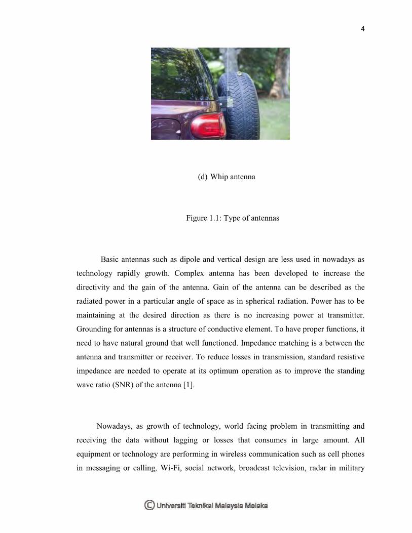
Antennas can be categorized into two types as according to its application. The
categories are omnidirectional and directional. Omnidirectional is a weak directional
antennas will receive or transmit in all directions. Sometimes it refers to horizontal
direction and reduced performance in sky. It is used at low frequency and low
applications where directional antenna is not highly required as to maintain the priced.
Example of omnidirectional antennas is whip antenna. Directional antenna is vice versa
to omnidirectional antennas. It is intended to maximize its coupling electromagnetic
field in its direction. It will receive and transmit in particular direction and large
frequencies are needed to operate it and high cost compared with omnidirectional
antennas. [2]
3
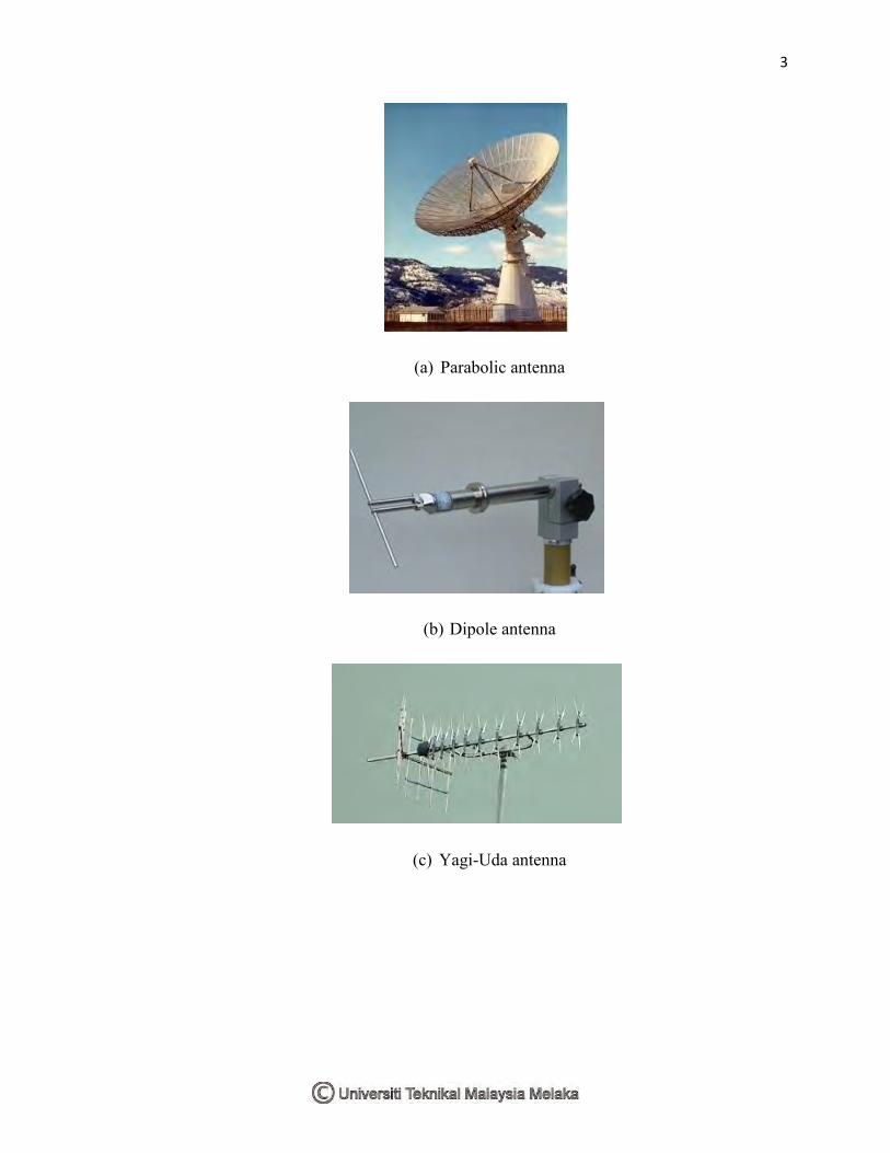
(a) Parabolic antenna
(b) Dipole antenna
(c) Yagi-Uda antenna
4
(d) Whip antenna
Figure 1.1: Type of antennas
Basic antennas such as dipole and vertical design are less used in nowadays as
technology rapidly growth. Complex antenna has been developed to increase the
directivity and the gain of the antenna. Gain of the antenna can be described as the
radiated power in a particular angle of space as in spherical radiation. Power has to be
maintaining at the desired direction as there is no increasing power at transmitter.
Grounding for antennas is a structure of conductive element. To have proper functions, it
need to have natural ground that well functioned. Impedance matching is a between the
antenna and transmitter or receiver. To reduce losses in transmission, standard resistive
impedance are needed to operate at its optimum operation as to improve the standing
wave ratio (SNR) of the antenna [1].
Nowadays, as growth of technology, world facing problem in transmitting and
receiving the data without lagging or losses that consumes in large amount. All
equipment or technology are performing in wireless communication such as cell phones
in messaging or calling, Wi-Fi, social network, broadcast television, radar in military
5
and many more required in wireless as in borderless world nowadays. Thus, in this new
era, it required an antenna that can perform better and less cost in producing it.
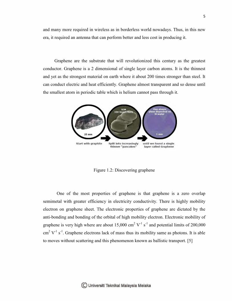
Graphene are the substrate that will revolutionized this century as the greatest
conductor. Graphene is a 2 dimensional of single layer carbon atoms. It is the thinnest
and yet as the strongest material on earth where it about 200 times stronger than steel. It
can conduct electric and heat efficiently. Graphene almost transparent and so dense until
the smallest atom in periodic table which is helium cannot pass through it.
Figure 1.2: Discovering graphene
One of the most properties of graphene is that graphene is a zero overlap
semimetal with greater efficiency in electricity conductivity. There is highly mobility
electron on graphene sheet. The electronic properties of graphene are dictated by the
anti-bonding and bonding of the orbital of high mobility electron. Electronic mobility of
graphene is very high where are about 15,000 cm2 V-1 s-1 and potential limits of 200,000
cm2 V-1 s-1. Graphene electrons lack of mass thus its mobility same as photons. It is able
to moves without scattering and this phenomenon known as ballistic transport. [5]
6
Other than electronic properties, graphene has extraordinary properties in
mechanical strength. Graphene has been known as the strongest material has been
discovered nowadays left behind diamond and steel. Approximately about
130,000,000,000 Pascal compared to 400,000,000 for structural steel or 375,700,000 for
Aramid substance that been used to build Kevlar. Even though graphene has this
strength, it only 0.77 milligrams per square meter and is 1000 times lighter than one
square per meter of paper. Graphene also has elastic properties even after being strain.
[5]
1.2 Problem Statement
Antenna is a device that is used to transmit and receive data which enables us to
communicate with each other regardless neither the place nor the region. The most
commonly used antenna for these recent years is the antenna built from copper
substance. However, antenna with copper substance has its disadvantages. One of the
disadvantages is that it lags the process of receiving and transmitting of data. This matter
is important to be discussed on followed by proper solution in order to increase the
efficiency of a communication process. Therefore, to overcome this problem, graphene
substance is likely to be introduced to replace the copper substance. Graphene substance
has the ability to increase the magnitude value of the power transmitted from a
transmitter to a receiver, giving it a strong justification to replace the existing antenna.
Graphene substance will also increase the gain and directivity of the transmitted signal.
This matter can be proven so, which is by applying graphene substance onto a wideband
omnidirectional planar microstrip antenna, whereby a Wideband Omnidirectional Planar
microstrip antenna is a thin layered rectangular shape structure that can be in form of
1x4, 1x6, 1x8 and 1x10 or else.
7
1.3 Project Objective
To make sure this project work as planned, a few objectives were determined where
these objectives will be followed as a guide through the whole completion process of
this project in order to achieve the desired output. These objectives were provided by
sequence of project from beginning until the end of project. A detailed explanation for
each objective will be discussed. There are several objectives that are to be achieved at
the end of the project which includes:
1) To design 1x4, 1x6, 1x8 and 1x10. Omnidirectional Planar Microstrip
antenna using Graphene and design it using CST Microwave studio software.
2) To compare the performance of copper and graphene as conductor for A
Wideband Omnidirectional Planar Microstrip Antenna for WLAN
Application.
3) To optimize the design the antenna design.
1.4 Scope
As to ensure the completion of project achieves the stated objectives, the project
shall be completed within these scopes:
1) Focus on 1x4, 1x6, 1x8 and 1x10. Omnidirectional Planar Microstrip antenna
using graphene as material.
2) Simulation using CST Microwave Studio software.
3) Target frequency from 2.4 GHz.
4) To compare performance of 1x4 coppers as patch material versus 1x4
graphene as patch material.
5) Parameter involved is for radiation pattern, parameter, bandwidth, gain,
realize gain and directivity.
8
1.5 Brief explanations on methodology
To achieve the goal that has been set in the objectives of this project, there are so
many works that need to be done. The first stage is learning the concept of microstrip
patch antenna and electronics properties of graphene and how the implementations in
antenna. The next stage are designing and simulating the antennas model in CST
software. Finally, compare and analyze the performance of the antennas. A detail
explanation for the parts will be explained in Chapter 3.
1.6 Report organizations
In this report, there are 5 chapters which are introduction, literature review,
methodology, result and conclusion and discussion. Not included in chapter is a
reference, abstract, table of content, table of picture and appendices.
Chapter one shows the introduction of this project. It contains the background of
the project and briefly explanation about the project methodology.
Chapter two consists of literature review of project. It covers the study of the
project such as the basic information of antenna, planar microstrip antenna, basic
information of graphene, and electronic properties of graphene that used in the project
for the future plan.
After that, it shows the choices can be made after all the study have been finished.
Chapter three shows about the methodology of the project. This chapter includes the
flow chart and Gantt chart of the project that shows the process of this project from start
till the end. By using the flow chat and Gantt chart, it can reduce an assumption that can
be made when doing the analysis.
Chapter 2
Literature Review
2.1 Literature Review
This chapter discuss about reviews of existing project created to get an idea
about the project design, conception and any information that related to improve the
project. With different concept and design, there are other creations and innovations of
projects done by other people.