a wood-powered lawn mower: separating the rules of thumb
TRANSCRIPT

Western Kentucky UniversityTopSCHOLAR®Honors College Capstone Experience/ThesisProjects Honors College at WKU
6-28-2017
A Wood-Powered Lawn Mower: Separating theRules of Thumb from Engineering DesignWilliam WhiteWestern Kentucky University, [email protected]
Follow this and additional works at: http://digitalcommons.wku.edu/stu_hon_theses
Part of the Biomaterials Commons, and the Heat Transfer, Combustion Commons
This Thesis is brought to you for free and open access by TopSCHOLAR®. It has been accepted for inclusion in Honors College Capstone Experience/Thesis Projects by an authorized administrator of TopSCHOLAR®. For more information, please contact [email protected].
Recommended CitationWhite, William, "A Wood-Powered Lawn Mower: Separating the Rules of Thumb from Engineering Design" (2017). Honors CollegeCapstone Experience/Thesis Projects. Paper 708.http://digitalcommons.wku.edu/stu_hon_theses/708
A WOOD-POWERED LAWN MOWER:
SEPARATING THE RULES OF THUMB FROM ENGINEERING DESIGN
A Capstone Project Presented in Partial Fulfillment
of the Requirements for the Degree Bachelor of Science in Mechanical Engineering
with Honors College Graduate Distinction at
Western Kentucky Univeristy
By
William D. White
May 2017
*****
CE/T Committee:
Professor Chris Byrne, Advisor
Professor Robert Choate

Copyright by
William D. White
2017

“To the King of the ages, immortal, invisible, the only God, be honor and glory
forever and ever. Amen.”
-1 Timothy 1:17

iv
ACKNOWLEDGEMENTS
This endeavor would have foundered if not for the guidance of Dr. Chris Byrne.
It has also depended greatly on the efforts of Eric Weaver and Colin Reece. Thanks is
due to Mr. Brian Hellinger and MTD who graciously provided a lawnmower and
monetary funding for the senior project. The WKU Libraries and Engineering
department have provided invaluable resources and assistance. Thanks to Sam White for
his unparalled assistance.
v
ABSTRACT
Biomass gasification, the thermal process of exracting combustible gasses from
organic matter, is an established procedure that has been used for many years to provide
fuel in various applications. It is a potential source of renewable fuel and has proven
useful as a crisis energy source.
This thesis investigates the primary engineering science principles involved in
gasifier-engine system design. It arises from and supplements a WKU mechanical
engineering senior project. The senior project has developed a wood gasification system
designed to power a riding lawn mower. The thesis reiews theory-based design and
separates it from informal hit and miss approaches—rule of thumb design. It presents an
overview of gasifier-engine systems and a discussion of accepted data and scientific
theory that contribute to their design. The process of fuel generation, the cleaning and
cooling of the fuel, and the engine interface are all investigated. Various concerns
involved in designing a gasifier-engine system are addressed. This thesis will assist the
creation of gasifier-engine systems via systematic engineering design by consolidating
and categorizing some of the existing information on biomass gasification.

vi
VITA
EDUCATION
Western Kentucky University , Bowling Green, KY Anticipated May 2017
B.S. in Mechanical Engineering – Mahurin Honors College Graduate
Firm Foundation Homeschool, Allen County, KY May 2013
PROFESSIONAL EXPERIENCE
WKU Department of Physics and Astronomy Spring 2015 – Present
Laboraory Learning Assistant
Arts Alive! Summer 2014 - Present
Summer camp staff member
AWARDS & HONORS
1906 Founder’s Scholarship, WKU, Fall 2013 – Spring 2017
President’s Scholar, WKU, Fall 2013 – Fall 2016
John Russel Award, WKU, Spring 2017
PROFESSIONAL MEMBERSHIPS
American Society of Mechanical Engineers (ASME)
Tau Beta Pi
Aircraft Owners and Pilots Association (AOPA)
INTERNATIONAL EXPERIENCE
East Asia mission trip March 2016
Central European conference volunteer January 2017
PRESENTATIONS
White, W., Choate, R., & Chidurala, M. (2017, March). Enhancing Student Learning
With a Wind Tunnel. Research presentation at the WKU Student Research Conference.
Bowling Green, KY.
vii
CONTENTS
Acknowledgements ............................................................................................................ iv
Abstract ............................................................................................................................... v
Vita ..................................................................................................................................... vi
List of Figures .................................................................................................................. viii
Section One: Introduction ................................................................................................... 1
Section Two: A Wood-Powered Lawn Mower .................................................................. 6
Section Three: Gasification................................................................................................. 8
Section Four: Conditioning ............................................................................................... 15
Section Five: Carburetion and Power Production ............................................................. 19
Section Six: Conclusion .................................................................................................... 23
References ......................................................................................................................... 24
Appendix 1: Fire tube length calculations ........................................................................ 25
Appendix 2: Senior project proposal ................................................................................ 26

viii
LIST OF FIGURES
Figure 1.1 Gasification process........................................................................................... 2
Figure 1.2 Gasifier-engine system. ..................................................................................... 5
Figure 3.1 Gasifier types. .................................................................................................... 8
Figure 3.2 Gasifier schematics. ........................................................................................... 9
Figure 3.3 Fire tube dimensions........................................................................................ 13
Figure 4.1 Cyclone dimensions......................................................................................... 16
Figure 5.1 Flame speeds. .................................................................................................. 20

1
SECTION ONE
INTRODUCTION
It is possible to extract combustible gasses out of organic matter such as wood. When
organic fuels are burned in an oxygen-starved environment, a gaseous mixture of nitrogen,
hydrogen, carbon monoxide, and methane may be produced. This mixture (called syngas) is
used as fuel to power ordinary internal combustion engines, though at a considerable loss of
power. The thermal process of creating such fuel is known as biomass gasification. It has been
researched and established through both scientific study and unscientific backyard projects. A
wide range of documentation is available to anyone wishing to make a gasification system, from
limited technical guides concerning scientific theory to random videos on the internet about
supposedly successful wood-powered projects.
When wood burns in an oxygen-rich environment, hydrocarbons in the wood convert to
carbon dioxide and water vapor, and energy is released. In an oxygen-limited environment,
wood can be pyrolyzed (or broken down by heat), releasing gases and producing charcoal though
no combustion occurs. Also, when combustion gases, pyrolysis gases, and charcoal are together
at high enough temperatures, reduction takes place through the Boudouard and water-gas
reactions.1 Equations 1.1 and 1.2 show these reactions with the associated energy. The negative
sign indicates that the reactions are endothermic.
Equation 1.1. Boudouard reaction.2 C + CO2 = 2CO -164.9 kJ/mole
Equation 1.2. Water-gas reaction.2 C + H2O = CO + H2 -122.6 kJ/mole
2
Temperatures above 600 °C are required for pyrolysis. The Boudouard and water-gas
reactions require temperatures over 800 °C, and they occur more rapidly as the temperature
increases beyond this. Since they draw energy from the environment, they naturally regulate the
temperature, which balance between 800 and 900 °C. A wood gasification system combusts
wood with a controlled air flow such that the oxygen is used up and some of the fuel is only
pyrolyzed instead of being completely burned. The heat from the initial burning provides energy
for pyrolysis and reduction. It is estimated that about 30% of the fuel is completely combusted
in order to provide this heat.1 The result is a mixture of nitrogen, hydrogen, carbon monoxide,
and methane. This wood gas or syngas, can be used to fuel many typical internal combustion
engines. Figure 1 displays a representation of the gasification process.
Figure 1.1. Gasification process. Source: Google images
Gasification is not a new concept. It has been used with many different fuel types though
charcoal and wood are the most common. It has powered a wide range of machines including
two-stroke and four-stroke engines as well as both gasoline and diesel engines. Discovered as
early as 1798, it was used to power city lights and iron smelting furnaces.1 For the first time in
the early 1880’s it was used to power a stationary engine.2 During the early 1900’s the use of

3
gasification branched out to trains, boats, and cars. Gasification did not see widespread use until
1939 when the onset of World War II brought about fuel shortages in Europe. By 1943,
gasification was used to power 90% of Sweden’s vehicles.1 Since that time it has become rare,
since liquid fuels like gasoline are more efficient and powerful.
Abundant practical experience provides a solid foundation for the design of gasification
systems that power engines. However, little is actually known about them scientifically. Work
has been done based on trial and error, rather than engineering science theory.3 Of the design
principles that exist, what are theory based and what are rules of thumb? What would be
involved in the systematic engineering design of a gasifier-engine system? According to
Generator Gas (page 98),“The designer of a perfect gas generator for vehicular operation must
consider many factors and must have an intimate knowledge of the physical and chemical
processes which determine the function of the gas generator.”2
The necessary functions of a gasifier-engine system can be grouped into four areas:
gasification, conditioning, carburetion, and power production. Each area has its own set of
design concerns and applicable scientific theory. A concept diagram of a gasifier-engine system
is shown in Figure 1.2. Naturally, cost, durability, and manufacturing expense are involved in
every area of a practical design.
The term “gasification” includes all functions involved in the production of syngas from
the biomass. Drying or otherwise preparing the biomass, channeling the biomass and oxidizer
flow, driving the flow, and igniting the biomass are all examples of such functions. The designer
of a unit that performs these functions will be concerned with flow rates, temperature gradient,
pressure gradient, and chemical concentrations and reactions. These general items of concern
4
are each affected by a host of specific design details such as biomass type, oxidizer composition,
and gasifier dimensions.
Conditioning generally refers to the cooling and filtration of syngas after it has been
produced before it can be used in an engine. The extent and nature of this part of the system
depend on the carburetion and power production units. If the syngas is used in an ordinary
internal combustion engine, tar and ash removal and reduction in temperature are important.
Related concerns include flow restriction, particle size, and temperature change.
Carburetion is the mixing of syngas with air and its delivery to the engine. Various
system interface difficulties may be involved here. Additional functions may be required such as
the ability to switch between syngas and some other fuel to power the engine during intermittent
syngas delivery. The designer of a syngas carburetion unit will need to consider the optimum
syngas/air mixture range and operating controls.
Power production refers to the set of functions that convert syngas and air flow into
useful power. General engine design will not be discussed. It is rare if not unheard of for an
engine to be designed specifically for use with syngas. However, the designer of a gasifier-
engine system must consider the compatibility of the power production system with the syngas
that is produced. For ordinary internal combustion engines many chemical qualities of the
syngas will be of importance along with their variation during operation. For optimum
performance, engine settings like compression ratio, valve timing, and ignition timing may be
affected by the density and burn rate of the syngas.
All the units that comprise a gasifier-engine system must be designed to match one
another. In almost every case, this will mean creating a gasifier to match the engine then a
conditioning and carbureting system to match both. Primarily, the gasifier must be of the
5
appropriate size to provide a sufficient fuel flow rate to the selected engine. The conditioning
system must be potent enough to reduce the syngas impurities to a level that is satisfactory for
the engine and must cool the gas to an appropriate density. The entire system must be assembled
with leak-proof connections in an arrangement that is practical for operation. This may involve
footprint size, weight, maintenance access, and engine vibration isolation.
Figure 1.2. Gasifier-engine system.
Fuel
Gasifier
Conditioner
Carburetor
Engine
• Shape and size • Energy content • Tar, ash, water content
• Fuel and oxidizer flow • Temperature • Ignition • Ash removal
• Particle filtration • Tar filtration • Water vapor removal • Syngas cooling • Pressure drop
• Mixture control • Fuel selection
• Power requirements • Compression ratio • Ignition timing • Valve timing
Power
Oxidizer

6
SECTION TWO
A WOOD-POWERED LAWN MOWER
This thesis arises from an existing mechanical engineering senior project. It will
contribute to this project as well as to other engineers seeking guidelines for systematic design.
The senior project team, Byrne Technical Design and Research, consists of three members: Eric
Weaver, Colin Reece, and Will White. The senior project has taken place over a year within the
context of two classes, ME 400 and ME 412. The team was tasked with designing and building a
wood gasification system that powers a riding lawnmower. Dr. Chris Byrne was the faculty
advisor for this project. The endeavor was co-sponsored by both Western Kentucky University
and MTD, an outdoor power equipment firm that provided both a riding lawn mower and
purchasing funds. During the fall of 2016, the team developed a design proposal. The proposal,
which outlines the entire project is appended to this document.
After taking steps to organize the team, specify requirements for their design, and plan
the project, the team proceeded with conceptualizing and selecting possible designs. A
significant portion of the work in fall 2016 was researching the process of wood gasification and
designs implemented in the past. Several important documents have provided the majority of the
information. These include two United States government sources, the 1988 Department of
Energy publication, Handbook of Biomass Downdraft Gasifier Engine Systems, and the 1989
FEMA article, Construction of a Simplified Wood Gas Generator for Fueling Internal
Combustion Engines in a Petroleum Emergency. A third valuable source has been Generator
Gas: The Swedish Experience from 1939-1945, which is a translation of a 1950 Swedish book
made for the United States Department of Energy.

7
The team project goal is a system, mounted on a WOLF-Garten Scooter Pro riding lawn
mower, that will power the mower with wood pellets for thirty minutes of normal operation
without refueling. Research and design work has led the team to select a stratified downdraft
gasifier design that will be accompanied with a cooling and filtration system and carburetor. The
design essentially follows the instructions of the 1989 FEMA document adapted to the lawn
mower. It primarily utilizes materials that can be found in hardware stores or scrapyards as
opposed to select components chosen through systematic engineering design decisions. For
example, the gasification unit is made with a 16 gallon drum and an old acetylene tank. The
team has fabricated the system and proceeded with testing, modifying, and verifying the design
in the Spring 2017 semester.

8
SECTION THREE
GASIFICATION
There are many different existing gasification system designs. Figure 3.1 displays a few
different types to ilustrte this diversity.
Figure 3.1. A few gasifier types including crossdraft, and Kalle.2
Fuel type is an important factor in overall design. It is important for the fuel to flow
freely and uniformly through the hearth of the gasifier. The hearth is a narrow region that causes
higher oxidant velocity and sustains high temperatures. Wood must be chunked or pelletized in
order to achieve such flow. From peach pits to safflower straw, biomass fuels vary greatly in
their ability to flow through the system as they are combusted, pyrolyzed, and removed. The
fuel feed components must be designed accordingly. The chemical composition of the fuel is
very important and can be determined with tests like proximate analysis and bomb calorimetry.
Fuel drying and ash removal components as well as the ignition method must be suited to the
selected fuel. Downdraft type gasifiers with a constricted hearth are necessary for wood
gasification. Only they cause temperatures high enough to decompose wood byproducts that
could be harmful to the engine.2 Oil vapors from wood break down at temperatures above 600°C

9
into hydrogen, carbon monoxide, carbon dioxide, and hydrocarbon gases like methane.1
Downdraft gasifiers also have good response times, so they are able to meet varying power
requirements. “Imbert” and “stratified downdraft” are the names of two important types of
downdraft gasifiers. These two designs are displayed in Figure 3.2.
Figure 3.2. Left: schematic of a WWII Imbert Gasifier. Right: a stratified downdraft gasifier.6
Both designs rely on suction from the engine to draw in air. The Imbert design draws air into
the hearth through nozzles arranged in a ring around the outside of the gasifier. The hearth is at
the bottom and the syngas outlet is at the top of an outer chamber. The lid above the
unpyrolyzed fuel must remain sealed. The stratified downdraft design consists of a fire tube with
a grate at the bottom. The gasification process occurs in “strata” as fuel moves down the fire
tube. First there is a zone of drying fuel, then a combustion and pyrolysis zone, then a char
reduction zone. In this design, air is pulled into the hearth (or pyrolysis zone) through the drying
fuel above. Thus the stratified downdraft design is also known as the “open top” gasifier.1 It

10
doesn’t require an airtight seal over the fuel container that would have to be opened for each
refueling. It is, in fact, a much newer design and is considered to have several advantages over
the Imbert design in practical or common use. It allows easier access for measuring hearth
conditions, accepts a larger variation of fuel types, and provides more even airflow through the
hearth eliminating hot spots.1
Critical elements in the design of any type of gasifier unit fuel storage and hearth
dimensions. Air is commonly used as the oxidizer, and the fuel type may also be predetermined.
But how does one size the hearth so that the appropriate flow rates and syngas generation will
occur? How quickly will the fuel be used up? Equation 3.1, from Generator Gas (page 110),
can calculate the biomass consumption rate.
Equation 3.12 𝑏 =623.3
𝑛𝑔∗𝑛𝑚𝑜𝑡∗𝐻𝑖
Where b is the specific fuel consumption (kg/hp*hr), ng is the gasifier efficiency, nmot is the
engine efficiency, and Hi is the effective heating value of the fuel. Average values are assumed
to be 0.8 gasifier efficiency, 0.22 engine efficiency, and 3520 kcal/kg heating value of wood.2
In a 1983 journal article titled A Predictive Model for Stratified Downdraft Gasification
of Biomass, Reed and Markson write, “The time for pyrolysis is all important in determining the
length of the flaming pyrolysis zone and hence the dimensions of the gasifier.”4 Beginning with
an existing mathematical model for combustion, they developed an expression for the duration of
pyrolysis based on the chemical reactions and heat transfer that occur in this zone. As updated in
a 1984 publication by Reed and Levie, the expression is shown in Equation 3.2.
Equation 3.25 𝑡𝑝 = (ℎ𝑝 + 𝐹𝑚ℎ𝑤)𝐹𝑑𝑉
𝐴𝑞
In Equation 3.2, tp is the time of pyrolysis; hp is the “heat of pyrolysis” or the total heat required
for the pyrolysis process. Fm is the moisture fraction in the fuel; hw is the heat for water

11
vaporization; Fd is the density of the fuel; V is the volume of a fuel particle; A is the surface area
of the fuel; and q is the heat flux. Experimentation estimates hp to be 2200 J/g and average q as 4
W/cm2. This equation is accompanied by a description of the velocity of the fuel as shown in
Equation 3.3.
Equation 3.35 𝑉𝑓 =𝑚
𝐴𝑔𝐹𝑑(1−𝐹𝑣)
Vf is the velocity of the fuel; m is the mass flow rate of biomass; Ag is the cross sectional area of
the gasifier and grate; Fd is the density of the fuel particles; and Fv is the void fraction or the
percentage of empty space in the region. Finally, Equation 3.4 gives the length of the pyrolysis
zone.
Equation 3.45 𝑙𝑝 = 𝑉𝑓𝑡𝑝
The length of the char gasification or reduction zone is similarly modeled by estimating the time
required for reduction and multiplying it by the velocity of the fuel flow. This is shown in
Equation 3.5
Equation 3.55 𝑙𝑔 = 𝑉𝑓𝑡𝑐
The char reduction time tc is again approximated though an analysis of the chemical reactions
involved. It is taken by these authors to be a constant. They use 100 seconds.
The times required to complete pyrolysis of the fuel and reduction of the char in
conjunction with the velocity of the fuel as it flows through the system give the length of the
zones where pyrolysis and reduction are occurring. By finding the theoretical length of the
pyrolysis and reduction zones the requisite dimensions of the firetube in a stratified downdraft
gasifier can be predicted. Presumably, similar models could be developed for other types of
gasifiers. Assuming the mass flow rate m used in Equation 3.3 could be taken as the fuel
consumption rate found with Equation 3.1 multiplied by the required horsepower. Thus, with an

12
iterative solution technique the gasifier can be sized according to the fuel type and engine
specifications.
In the Handboook of Biomass Downdraft Gasifier Engine Systems a more simple method
is sugested for determining the hearth dimensions. The throat constriction diameter for an
Imbert gasifier is found as shown in Equation 3.6. The diameter of the hearth or firetube for a
stratified downdraft design is found with Equation 3.7.
Equation 3.61 𝐷 = 1.6√𝑃 𝑐𝑚
Equation 3.61 𝐷 = 1.6√𝑃 𝑖𝑛
In these equations the diameter is D, oddly given in centimeters for the imbert design (Equation
3.6) and in inches for the stratified design. P is the power requirement in horsepower. It is not
clear how this method was derived.
In the FEMA document a table is given providing sizing information with which to scale
the firetube of a stratified downdraft gasifier to the size of the engine. This table is shown in
figure 3.3.
13
Figure 3.3. Stratified downdraft gasifier fire tube dimensions based on engine size.6
No source is cited for the information in this table, so it is unclear how these dimensions were
obtained.
The diameters of Figure 3.3 roughly agree with those suggested by Equations 3.6. The
method suggested based on Equations 3.1 through 3.5 was used based on values put forth in the
document cited as well as the horsepower values and diameters listed in Figure 3.3. The
resulting firetube lengths were in the same range as those of Figure 3.3 but with an opposite
trend. These calculations are shown in Appendix 1.
Any rule of thumb guide like Figure 3.3 or Equations 3.5 and 3.6 makes many
assumptions about the fuel and operating conditions. With careful consideration of certain
details, gasifier design can more accurately conform to the intended use. In most cases, a
gasifier will need to cope with a large range of fuel shapes, sizes, and compositions, as well as
fluctuating air input, and combustion temperatures. The dimensions must be sufficient for this

14
range. For well controled operation, or for designs that seek to maximize efficiency in specific
ranges of conditions, systematic engineering design will include a thorough analysis of the
gasification process.
15
SECTION FOUR
CONDITIONING
The design of cleaning and cooling units for syngas depends not only on the engine to
which the syngas will be delivered but also on the gasification unit and fuel that were used to
create it. Charcoal generally creates cleaner gas than wood, which produces tars and water
vapor. Both may leave ash or soot particles. Abrasion and clogging can both be problems when
the sygas powers an internl combustion engine. Some gasifier designs allow more tar and
pollutants to remain in the syngas than others do. Syngas is considered dirty when it contains at
least 100 mg/Nm3 of particles with an average size of 100 μm and 1000 mg/Nm3 of tar. Though
some gasifiers operate very cleanly in some conditions, all occasionally produce dirty syngas.
Gasifier-engine systems have been successful in the past with less than 10 mg/Nm3.1 The extent
to which the syngas is cooled will be based on a balance between the increased engine efficiency
with a more dense fuel and the power loss due to increased flow resistance. Cooling the syngas
also allows for the condensation and extraction of water vapor, which otherwise decreases the
quality.
Common conditioning designs include a simple container filled with filter media such as
sawdust, charcoal, or straw and some sort of heat exchanger with the surrounding air. The
syngas is piped into the filter container and forced through layers of filter media which can be
periodically replaced as they become dirty and clog. The syngas then flows through a series of
pipes or ducts that allow it to release heat to the ambient air. A cyclone seems to be a good first
stage filter to remove heavier particles and tar. A cyclone is a centrifugal particle removal
device that extracts heavy particles and liquid impurities by swirling them around in a constricted
pipe. They can be designed to fit the given gas flow system based on the mass or volume flow
16
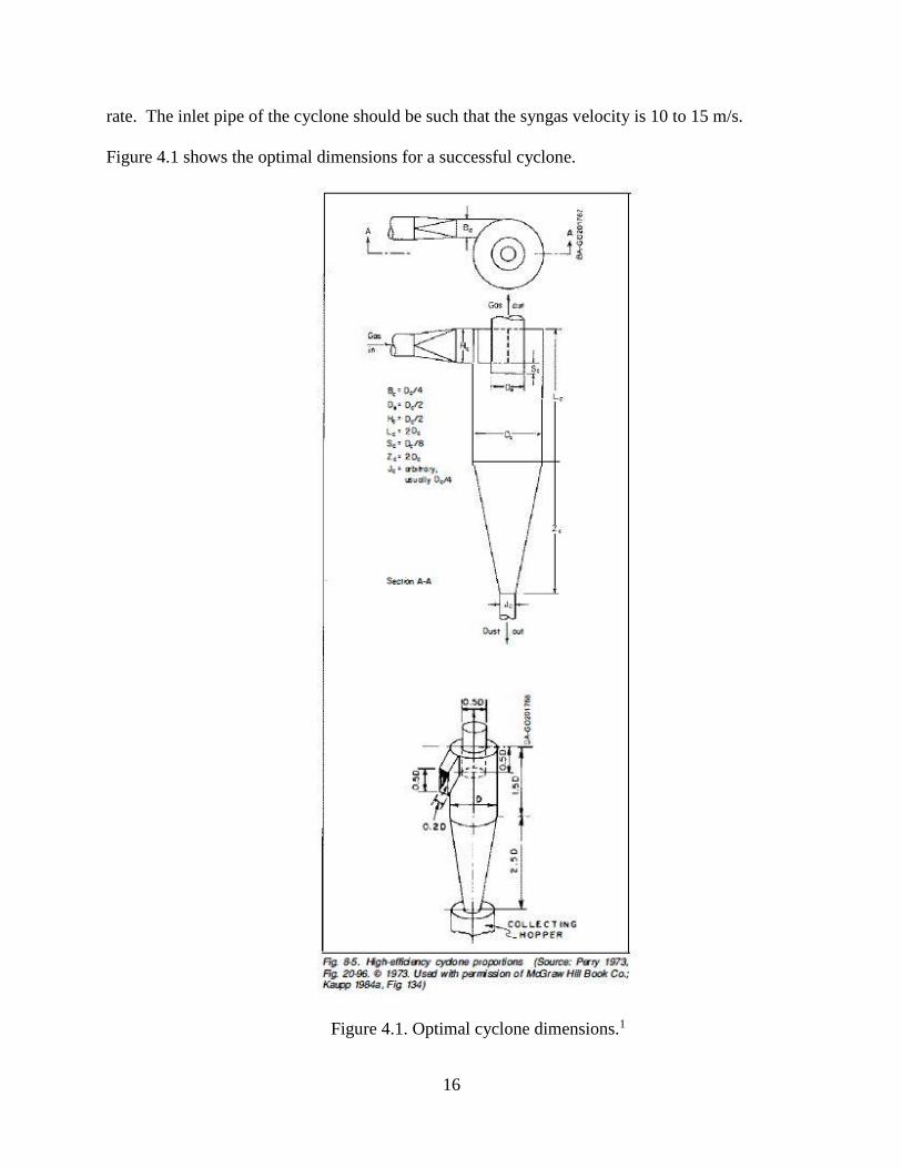
rate. The inlet pipe of the cyclone should be such that the syngas velocity is 10 to 15 m/s.
Figure 4.1 shows the optimal dimensions for a successful cyclone.
Figure 4.1. Optimal cyclone dimensions.1

17
Using the same wood chips in the filter container as those to be gasified is suggested in
the FEMA document. It states that a five gallon paint can, “seems to be sufficient” as a filter
container for gasifiers with fire tubes up to 10 inches in diameter.6 This is a very helpful
statement of experiential knowledge. More useful to systematic design, however, would be to
quantify the severity of the pollutants commonly produced by such gasifier units and the
filtration capability of the filter design. A filter could be selected and sized appropriately based
on the expected flow rate, the available space, and the preferred frequency of filter media
replacement.
The systematic design of a syngas cooling unit requires some application of heat transfer
theory. According to the FEMA document, 70 °F is the ideal temperature at carburetion. It
estimates that 1% of the engine’s horsepower is lost for every 10 °F above this.6 Again, a
problem that the designer will face is balancing the benefit of temperature drop with the
detriment of flow resistance. Heat exchangers may be designed that bring the two fluids to
equilibrium temperature using relatively little space, but this comes at the cost of a high pressure
drop. In the case of a gasifier-engine system, space is often a concern, especially since many
applications are on vehicles where adding weight and size can be a difficult design issue itself.
Pressure drop over the system will require increased power from whatever is driving the flow.
Whether the syngas is drawn through the system with an independent blower or, as is very
common, by the suction of the engine itself, this extra power requirement may outweigh the
benefit of cooler syngas.

18
SECTION FIVE
CARBURETION AND POWER PRODUCTION
Since gasifier-engine systems are almost always designed around an existing engine to
power it with a secondary fuel source, syngas carburetion designs may simply be an addition to
or interruption of the previous carburetor. They commonly include a mixture adjustment that
allows the user to control the amount of airflow introduced to the syngas. The original throttle
may be used and everything else about the engine may remain unchanged. However, depending
on the engine type, many changes or additions can improve the efficiency and effectiveness of
syngas operation.
Syngas can vary in quality during production. The amount of air that must be added to
the syngas in order to produce the optimum mixture may need to be adjusted during the
operation of the system. Changes in the syngas/air ratio can have a more dramatic effect than
changes in a gasoline/air ratio.1 So a mixture adjustment available at all times to the operator
may be necessary. Syngas carburetion systems may require especially well controlled valves in
order to manage the touchy mixture.
While gasoline produces the most power at mixtures slightly richer than stoichiometric
(equal ammounts of fuel and air), syngas mixtures are more potent when there is an excess of
air.1 An investigation into the combustion reactions, reaction rates, and densities of air and
syngas will enable the designer to select the best mixture. A ratio of 1 or 1.1 parts air to 1 part
syngas by volume is said to be the ideal.1, 6
When adapting an existing engine for syngas operation, maintaining the original fuel
delivery system is advisable for gasoline engines and necessary for diesel engines. In diesel
engines, some original fuel must be mixed with the syngas to make it ignite. Starting the engine
19
on the original fuel may be helpful for beginning syngas operation. Commonly, a separate fan or
blower provides suction to start the gasification process and the syngas burns off in a flume. The
engine is started on the original fuel. Then the blower is turned off and a system of valves opens
the engine to the gasification system while shutting off the original fuel.
Spark plug adjustment and even valve timing or compression ratio changes can optimize
the efficiency of the engine when operating on syngas. Syngas has a different range of densities
and burn rates than gasoline or diesel. This means that to obtain the best volumetric efficiency,
the valves may have to be open at different times or for a different duration. Ignition timing may
have to be retarded or advanced because the flame front does not propagate at the same speed as
it does in gasoline. Spark plug gaps may need to be adjusted because the syngas/air misture may
have a different dielectric strength than the gasoline/air mixture. The syngas mixture may
breakdown at a different maximum electric field allowing a spark at a different voltage or spark
plug gap.7
The FEMA document recommends that the ignition timing be set to “early,” and the
spark plug gaps be set between 0.012 and 0.015 in.6 It has, in fact, been observed that 5 to 15
degrees before “advance” is most effective. Syngas is known to have a slower burn rate than
gasoline. Figure 5.1 shows the flame speeds of various syngas components and air.

20
Figure 5.1. Flame speed of various syngas components.1
The ignition timing can be based on the information given in Figure 5.1. Syngas operation
requires that about twice as much total gas volume enter the engine than during gasoline
operation. Cam shafts should tend toward faster opening, higher lift, and no overlap.1
Experience has shown that butterfly valves, which are often used in carburetors and throttles,
may be too active for syngas carburetion. The non-linear response of butterfly valves makes
finding the optimum mixture difficult. Gate valves are recommended instead.1 The compression
ratio in an engine operating with syngas can be higher than what is allowable with gasoline.
21
According to the Handboook of Biomass Downdraft Gasifier Engine Systems, it can be raised to
between 11:1 and 14:1.1 This can help the engine reach maximum efficiency and make up for
some of the power that is lost as a result of using syngas.
All of this general guidance may or may not apply to the specific system being designed.
For systematic design, the affects of the mixture, the burn rate, the density after cooling, and the
dielectric strength should be investigated. These will guide carburetor design and the selection
or modification of a power production system.

22
SECTION 6
CONCLUSION
The engineering senior project from which this thesis springs followed published
recommendations for the design of a gasifier-engine system. The project utilized a stratified
downdraft gasifier, a cyclone separator, and a filter unit to provide syngas to a riding lawn
mower. Most design decisions were based on the published advice and the team’s interpretation
and adjustment of those guidelines, apdapting the system to the lawn mower that was provided
by MTD. Informality and narrowness marked much of the available information. The team
essentially had to follow guidelines that were too specific and uninformative, provided by
numerous successful experimenters each with his own particular system. Such guidelines may or
may not hold true as the application, and therefore certain design details, change.
Biomass gasification remains a well-established process in practice yet apparently
without substantial theoretical understanding. Mathematical modeling of the gasification process
is very complicated and may continue to change and improve over time. Various methods of
filtering and cooling gasses and the concepts involved are well known, but specific methods for
syngas are not cleary established. Engines have long been made to run on syngas, and the best
operating principles may be known, but why are these so? We know what works, but why? The
ability to systematically design and predict the performance of totally new gasifier-engine
systems is limited until such questions can be answered.

23
REFERENCES
1. T. B. Reed and A. Das, Handbook of Biomass Downdraft Gasifier Engine Systems,
SERI/SP-271-3022, (Solar Energy Research Institute, Golden, CO, 1988)
2. T. B. Reed and D. Jantzen, Generator Gas: The Swedish Experience from 1939-1945 (a
translation of the Swedish book, Gengas), SERI/SP-33-140, (Solar Energy Research
Institute, Golden, CO, 1979)
3. C. S. Chee, Analysis, Modeling, and Control of a Comercial-Scale Downdraft Gasifier,
(Kansas State University, Manhattan, KS, 1990)
4. T. B. Reed and M. Markson, “A Predictive Model for Stratified Downdrft Gasification of
Biomass,” Progress in Biomass Conversion 4, 217-254 (1983)
5. T. B. Reed and B. Levie, “A Simplified Model of the Stratified Downdraft Gasifier,” in
The International Bio-Energy Directory and Handbook 1984 (The Bio-Energy Council,
Washington, D.C., 1984) 379-389
6. H. LaFontaine and F. P. Zimmerman, Construction of a Simplified Wood Gas Generator
for Fueling Internal Combustion Engines in a Petroleum Emergency (Federal Emergency
Management Agency, Washington, D.C., 1989)
7. R. D. Knight, Physics for Scientists and Engineers: A Strategic Approach (Pearson,
Boston, 2013)

1
APPENDIX 1: FIRE TUBE LENGTH CALCULATIONS
hp D (in) Ag (in^2) Fd (g/cm^3) Fv m (kg/hr) m (kg/s) Tp (s) Tc (s)
5 2 3.141593 0.4 0.5 5.03 0.001397 43 100
15 4 12.56637 0.4 0.5 15.09 0.004192 43 100
30 6 28.27433 0.4 0.5 30.18 0.008383 43 100
40 7 38.48451 0.4 0.5 40.24 0.011178 43 100
50 8 50.26548 0.4 0.5 50.3 0.013972 43 100
65 9 63.61725 0.4 0.5 65.39 0.018164 43 100
80 10 78.53982 0.4 0.5 80.48 0.022356 43 100
100 11 95.03318 0.4 0.5 100.6 0.027944 43 100
120 12 113.0973 0.4 0.5 120.72 0.033533 43 100
140 13 132.7323 0.4 0.5 140.84 0.039122 43 100
160 14 153.938 0.4 0.5 160.96 0.044711 43 100
Ag (m^2) Fd (kg/m^2) Vf (m/s)
0.002027 400 0.003447
0.008107 400 0.002585
0.018241 400 0.002298
0.024829 400 0.002251
0.032429 400 0.002154
0.041043 400 0.002213
0.050671 400 0.002206
0.061312 400 0.002279
0.072966 400 0.002298
0.085634 400 0.002284
0.099315 400 0.002251
Lp (m) Lc (m) length (m) length (in)
0.148 0.345 0.49 19.41
0.111 0.259 0.37 14.55
0.099 0.230 0.33 12.94
0.097 0.225 0.32 12.67
0.093 0.215 0.31 12.13
0.095 0.221 0.32 12.46
0.095 0.221 0.32 12.42
0.098 0.228 0.33 12.83
0.099 0.230 0.33 12.94
0.098 0.228 0.33 12.86
0.097 0.225 0.32 12.67

2
APPENDIX 2: SENIOR PROJECT PROPOSAL
Byrne
TDR
Colin Reece, Eric Weaver, Will White Wood Gasification Powered Lawnmower
Project Proposal
Western Kentucky University
Department of Mechanical Engineering
Fall Semester 2016

3
Table of Contents
A. Executive Summary
B. Company Background
C. Gasification Background
D. Project Requirements and Specifications
E. Fall Macro Plan
F. Team Responsibilities
G. Design and Decision Process
a. Gasifier
b. Gas Processing System
c. Starting System
d. Fuel Delivery to the Engine
H. Operation
I. Cost Analysis
J. Spring Macro Plan
4
A. Executive Summary
Our senior project team, Byrne Technical Design and Research, consists of three
members, Eric Weaver, Colin Reece, and Will White. We were tasked with developing a
wood gasification system that powers a riding lawnmower. Dr. Chris Byrne is the faculty
advisor for this project. The endeavor is co-sponsored by both WKU and MTD. During
the fall of 2016, we have developed a possible design.
After taking steps to organize our team, specify requirements for our design, and
plan out our project, we proceeded with conceptualizing and selecting possible designs.
A significant portion of our work this fall has been researching the process of wood
gasification and the designs that have been implemented in the past. Our goal is a
system, mounted on a WOLF-Garten Scooter Pro riding lawn mower, that will power the
mower with wood pellets for thirty minutes of normal operation without refueling. Our
research and design work has led us to select a stratified downdraft gasifier design that
will be accompanied with a cooling and filtration system and carburetor.
B. Company Background
MTD, headquartered in Valley City, Ohio, is a leading producer of outdoor power
equipment for both personal and commercial use. They are an international company
with production facilities in Europe, North America, Asia, and Australia. They also
provide distribution throughout South America. Because of their passion for new
technology and innovation, MTD has decided to sponsor Byrne TDR in conjunction with
WKU to assist in the design and assembly of a lawn mower powered by wood gas. MTD
has donated the Wolf Garten riding lawn mower that is currently being used.

5
C. Gasification Background
Gasification is the process of producing combustible gasses from materials like
wood or charcoal. When done properly, typical internal combustion engines can be run
on the gasses that are produced. When wood is burned in an oxygen-rich environment,
hydrocarbons in the wood are converted to carbon dioxide and water vapor, and energy is
released. In an oxygen-limited environment, wood can be pyrolized or broken down by
heat, releasing gases and producing charcoal though the gases may not be burned. Also,
when the pyrolysis gases and charcoal are together at high enough temperatures,
reduction takes place through the Boudouard and water-gas reactions1. Both pyrolysis
and reduction require energy, but they result in the production of hydrogen and carbon
monoxide gas. A wood gasification system burns wood with a controlled air flow such
that the oxygen is used up and some of the fuel is only pyrolized instead of being
completely burned. The heat from the initial burning provides energy for pyrolysis and
reduction. The result is a mixture of Nitrogen, Hydrogen, Carbon Monoxide, and
Methane. This wood gas or syngas, can be used to fuel many typical internal combustion
engines. Figure 1 displays a representation of the gasification process.
1Handbook of Biomass Downdraft Gasifier Engine Systems, pg. 29

6
Gasification for fueling passenger vehicles first started in the 1920s with the
research of George Imbert, a German engineer who designed the first mobile wood gas
generator. His design was used extensively during World War II due to the shortage of
gasoline in most of Europe. His research led to some 500,000 vehicles running on wood
gasification in Germany alone. More research was done in Sweden as well by the
Academy of Swedish Engineers, who were funded by the Swedish Parliament. Their
research led to an additional 73,000 vehicles running on wood gasification on Swedish
roads. All told during WWII, there were an estimated 708,000 vehicles using wood
gasification across Europe. Unfortunately, after WWII the technology decreased in
popularity dramatically due to the added hassle involved in fitting the system to vehicles.
The convenience of liquid fuels outweighed the environmental and economic benefits for
most consumers. This being said, wood gasification made a brief resurgence during the
early 1980s in the United States due to gasoline shortage. It is also being explored today
Figure 1: Gasification process. Image from Google images

7
as a more sustainable fuel alternative that is more environmentally friendly when
compared to gasoline.
D. Project Requirements & Specs
For our particular system, we required a wood gasification system that:
is capable of powering a riding lawn mower under load
Does not affect the safety and control of the mower
Is sturdy enough to withstand the strains induced by typical lawn mower
operation
Is able to be cleaned and maintained with relative ease
Provides a simple method for fuel replenishment
Has enough fuel capacity for 30 minutes of continuous operation of the mower
Maintains similar functionality when compared to a gasoline system
Is operated using wood pellets as fuel
For these requirements, our team set the following specifications:
System must produce 35 cfm of gas, so as to generate 12HP at an operating
engine speed of 3000 RPM
System must not extend more than 6 inches beyond the width of the original
mower to maintain maneuverability
System must be as close to the original chassis with regards to extension off the
back of the mower to limit the amount of space required for storage and to
maintain structural strength. The team set a limit of 18 in off the back to maintain
the original footprint that was left by the grass catcher, which was removed.

8
E. Fall Macro plan
Our project can easily be broken into several distinct components with a few
deadlines throughout the semester. The components of our project included research,
documentation, a syngas generator or gasifier, a syngas processing system, and a system
for mounting everything to the mower. Throughout the semester several deadlines were
paramount such as the design reviews and the proposal. Each of the components had
specific milestones to be attained by these deadlines. These milestones are outlined in the
flowchart provided by figure 2.
Figure 2: Flowchart for the macro plan used to plan our project efforts during the fall semester
9
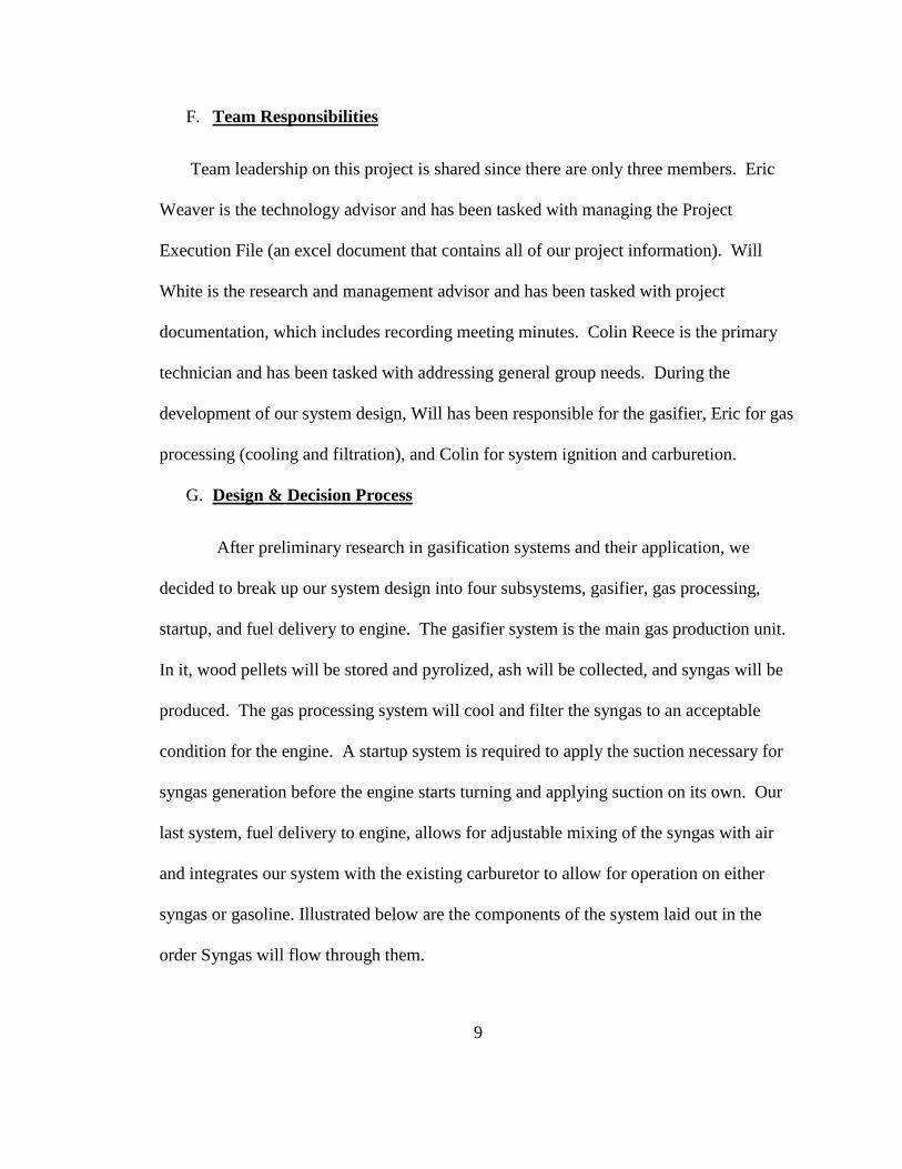
F. Team Responsibilities
Team leadership on this project is shared since there are only three members. Eric
Weaver is the technology advisor and has been tasked with managing the Project
Execution File (an excel document that contains all of our project information). Will
White is the research and management advisor and has been tasked with project
documentation, which includes recording meeting minutes. Colin Reece is the primary
technician and has been tasked with addressing general group needs. During the
development of our system design, Will has been responsible for the gasifier, Eric for gas
processing (cooling and filtration), and Colin for system ignition and carburetion.
G. Design & Decision Process
After preliminary research in gasification systems and their application, we
decided to break up our system design into four subsystems, gasifier, gas processing,
startup, and fuel delivery to engine. The gasifier system is the main gas production unit.
In it, wood pellets will be stored and pyrolized, ash will be collected, and syngas will be
produced. The gas processing system will cool and filter the syngas to an acceptable
condition for the engine. A startup system is required to apply the suction necessary for
syngas generation before the engine starts turning and applying suction on its own. Our
last system, fuel delivery to engine, allows for adjustable mixing of the syngas with air
and integrates our system with the existing carburetor to allow for operation on either
syngas or gasoline. Illustrated below are the components of the system laid out in the
order Syngas will flow through them.
10
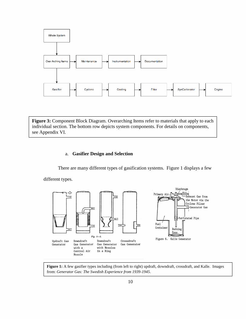
a. Gasifier Design and Selection
There are many different types of gasification systems. Figure 1 displays a few
different types.
Figure 1: A few gasifier types including (from left to right) updraft, downdraft, crossdraft, and Kalle. Images
from: Generator Gas: The Swedish Experience from 1939-1945.
Figure 3: Component Block Diagram. Overarching Items refer to materials that apply to each
individual section. The bottom row depicts system components. For details on components,
see Appendix VI.

11
Downdraft type gasifiers with a constricted hearth are necessary for wood gasification
because only they cause high enough temperatures to decompose wood byproduct that
could be harmful to the engine2. We have found thorough background information for
two types of downdraft gasifiers, Imbert and stratified downdraft. These two designs are
displayed in Figure 2.
Both designs rely on suction from the engine to draw in air. The Imbert design draws air
into the hearth through nozzles arranged in a ring around the outside of the gasifier. The
hearth is at the bottom and the syngas outlet is at the top of an outer chamber. The lid
2 Generator Gas: The Swedish Experience from 1939-1945, pg. 110
Figure 2: Left: schematic of a WWII Imbert Gasifier. Right: schematic of a stratified downdraft gasifier.
Images from: Construction of a Simplified Wood Gas Generator for Fueling Internal Combustion Engines in a
Petroleum Emergency.

12
above the unpyrolyzed fuel must remain sealed. The stratified downdraft design consists
of a fire tube with a grate at the bottom. The gasification process occurs in “strata” as
fuel moves down the fire tube, first there is a zone of drying fuel, then a flaming
pyrolysis zone, then a char reduction zone. In this design, air is pulled into the hearth (or
pyrolysis zone) through the drying fuel above. Thus the stratified downdraft design is
also known as the “open top” gasifier3. Because the stratified downdraft design doesn’t
require an airtight seal over the fuel container that would have to be opened for each
refueling, we preferred it over the Imbert. The stratified downdraft design is also simpler
and hopefully easier to construct and maintain. A design selection matrix comparing
these two gasifier designs is shown in Appendix 1. Further research has confirmed our
preference to the stratified downdraft design. It is, in fact, a much newer design and is
considered to have several advantages over the Imbert design as far as practical or
common use go. In addition to the points we noted, it allows easier access for measuring
hearth conditions, accepts a larger variation of fuel types, and provides more even airflow
through the hearth eliminating hot spots4.
To develop a stratified downdraft gasifier design we have heavily relied on a 1989
Federal Emergency Management Agency publication titled Construction of a Simplified
Wood Gas Generator for Fueling Internal Combustion Engines in a Petroleum
Emergency. The schematic of the design laid out in this document is shown in Appendix
II,b. Modifying the design put forth in this document to fit our design constraints has not
3 Handbook of Biomass Downdraft Gasifier Engine Systems, pg. 38 4 Handbook of Biomass Downdraft Gasifier Engine Systems, pg. 39
13
been an insurmountable task. Minimizing size, weight, and complexity were driving
forces in the changes we made. Our lawn mower runs on a 8.2 kW or 11 hp engine. The
design shown in the FEMA document was for a 35 hp engine, but information is given on
how to scale the design. Because we are only seeking 30 minutes of operation before
refueling, we were able to replace the large fuel hopper included in the FEMA design
with a much smaller piece of ductwork. Our fuel consumption calculations were done
using the equation provided in the 1950 U.S. Department of Energy document, Generator
Gas: The Swedish Experience from 1939-1945. We took the effective heating value and
bulk density of wood pellets from Southern Maine Renewable Fuels. The FEMA design
includes a grate shaker that protrudes into the main chamber of the gasifier (which must
be airtight). The grate shaker is used to agitate the grate at the bottom of the fire tube,
which hangs freely from chains, and force clogging ash to fall out. We decided to replace
this component with a simple access port that will allow for ignition, ash cleanout, and
grate shaking when the gasifier is not operating. Since our gasifier will be operating on a
lawn mower, the grate should not need to be manually shaken during operation5. Our
design uses a 16 gallon steel drum for the main gasifier chamber and an old acetylene
tank for the fire tube. We hope to utilize as many scrap components as possible. This
method has shown success in the past6. Preliminary design sketches are shown in
Appendix II,c. A sketch of our final design is shown in Figure 5.
5 FEMA, 1989, Construction of a Simplified Wood Gas Generator for Fueling Internal
Combustion Engines in a Petroleum Emergency, section 1.3.2. 6 FEMA, 1989, Construction of a Simplified Wood Gas Generator for Fueling Internal
Combustion Engines in a Petroleum Emergency, section 1.1.

14
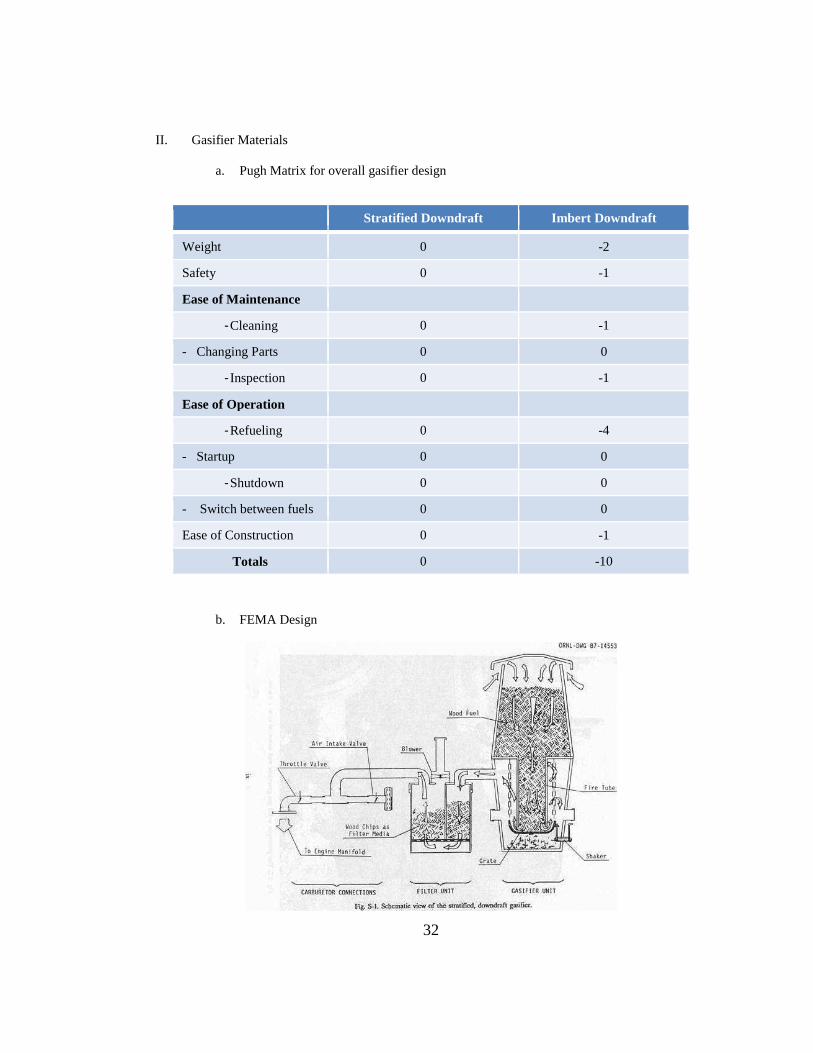
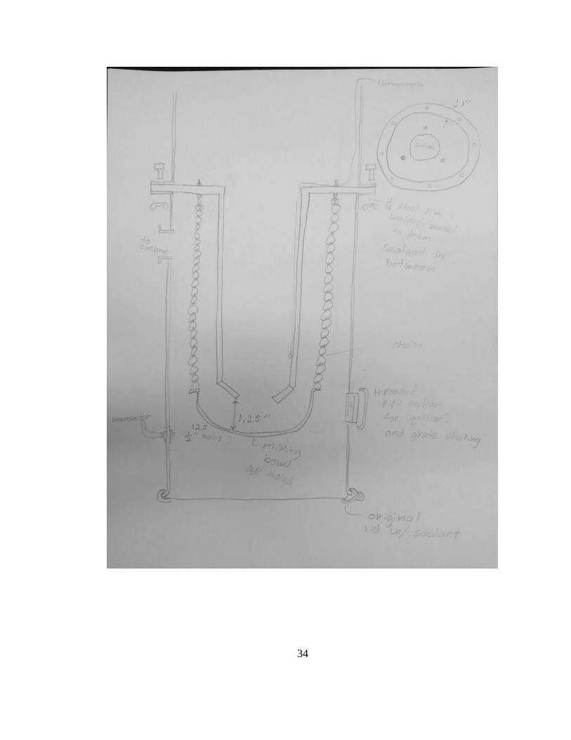
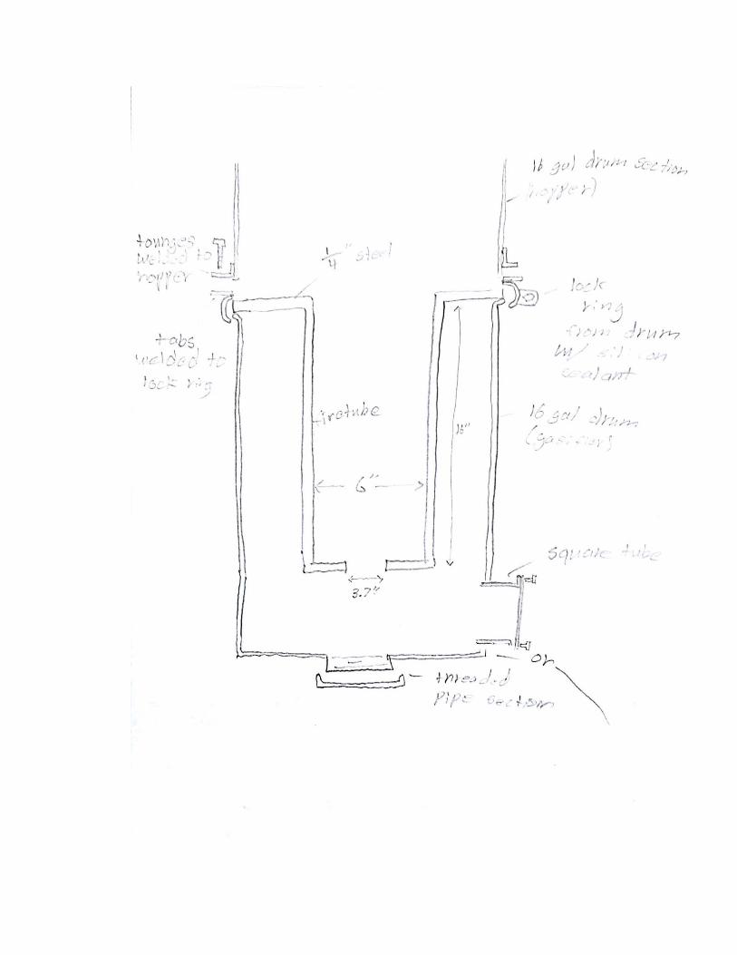
Figure 5: Gasifier design
We have added a shielded thermocouple running down the fire tube to monitor
hearth temperature and a simple manometer to monitor the pressure drop at the end of the

15
filter unit. These instruments will allow us to know if the system is operating at an
acceptable temperature with no blockages. We also added a sleeve of high temperature
insulation to go around the outside of our fire tube to improve efficiency7. The acetylene
tank fire tube will be welded to a 1/4 inch steel plate cut to the size of the drum rim. This
plate will replace the lid of the drum and will be held to the drum with the original clamp
ring with high temperature silicon sealant. The grate will be a stainless steel strainer
bowl with the holes modified as necessary, suspended with lightweight chain from the
1/4 inch plate so that it hangs 1 ¼ inch from the bottom of the fire tube. The acetylene
tank will have both ends cut off so that the bottom has a 3.7 inch constriction. The access
port will be a 4 inch diameter threaded steel pipe nipple and cap brazed to the side of the
drum near the bottom of the fire tube. The gasifier and the filter unit will be mounted to
an existing steel frame on the back of the lawn mower. Steel tabs will be welded to the
bottom of this frame for the edge of the barrels to set on and steel bands will wrap around
the barrels and be tightened to the frame with bolts with wing nuts.
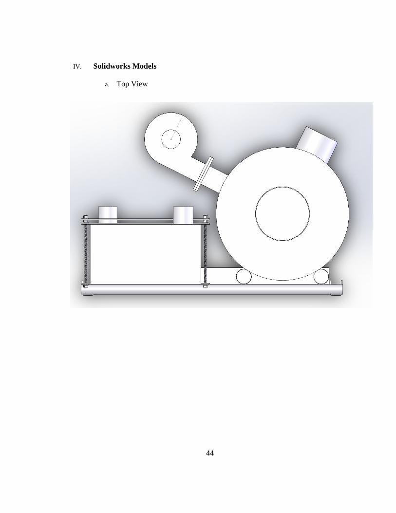
b. Gas Processing
Once the gas is produced it needs to be filtered, cleaned, and cooled before entering the
engine. The gas processing system includes any filtering or cooling processes performed
on the gas between the gasifier and the engine. Particulates and tar in the syngas can
cause accelerated wear within the engine requiring more frequent maintenance and an
accelerated rebuild schedule. Water in the syngas can also cause issues with the piping
7 U.S. Department of Energy, 1950, Generator Gas: The Swedish Experience from 1939-
1945, pg. 115.

16
system and the engine. These are reasons the syngas needs to be filtered before reaching
the engine.
For the first stage of filtering we chose to attach a cyclone to the syngas outlet on
the gasifier. The cyclone removes larger particles and any liquid from the syngas stream
before it enters tubing that could suffer from tar buildup. A few of the benefits of the
cyclone is its small footprint and ease of cleaning. The cyclone will deposit collected
material in a glass jar screwed to the bottom, allowing easy to removal of debris. The
cyclone is attached to the gasifier, allowing for some flexibility when mounting the
system to the lawn mower and minimizing the number of components requirering
attachment to the lawn mower. Concern has been voiced that the weight of the cyclone
could cause stresses too great for the thin wall of the barrel to withstand. Especially when
the mower is in operation over rough terrain. A brace near the bottom of the cyclone has
been devised as a solution for minimizing this concern. The brace is illustrated in figure
1. The plan for the brace is to have a tab welded to the gasifier onto which the brace from
the cyclone can be bolted. This allows for removal of the cyclone for cleaning.

17
For the second stage of filtering, we are piping the syngas through a container
filled with filter media. The purpose of this stage is to remove smaller particles from the
fuel stream as well as any water that has condensed by the time it reaches the filter. There
is a wide variety of filter media which can be used but we are planning to do our initial
test with straw topped by sawdust. The straw acts as more of a coarse filter while the
sawdust can act as a fine filter removing even smaller particles and more liquid.
Several iterations of designs using a metal five-gallon bucket as the filter
container were considered. A metal bucket was considered since a plastic bucket would
likely become quite pliable with the temperature of the syngas and create sealing issues.
One of the main considerations when choosing a filter container was ease of access and
service since the filter media will inevitably need to be replaced. This led to issues with a
Figure 1: Shows cyclone attached to gasifier with support solution

18
metal bucket since the lid is secured by bending ears of metal. After removing and
replacing the lid a few times it would become difficult to seal as the lid warps and the
ears become weaker from fatigue due to cycling. These issues led us to ammo cans.
Ammo cans are made of thicker steel and they are rectangular. These two
attributes make them easier to mount than thin-walled cylindrical barrels. Considering the
rectangular shape of the container, it also becomes cheaper and easier to manufacture or
build the plate used to keep the filter media off of the floor. This can be accomplished
quite simply with a piece of steel plate with a few holes drilled in it and a few bolts and
nuts. Ammo cans also come standard with a cam locking lid that seals very tightly to the
container with a rubber gasket. A lid system such as this makes for easy access to the
container. This ease of access fulfills our requirement for ease of service. Each of these
aspects make an ammo can more desirable than a 5-gallon bucket. For the final design we
have decided to use a 120mm ammo can for the filter unit. The ammo can design is
shown in figure 2.

19
As for interfacing with the rest of the system, the gasifier will have a pipe or
tubing with a flange. This can be seen in the SolidWorks modeling found in the appendix.
The cyclone will have a matching pipe or tube and flange between which a gasket or high
temp sealant will be used to maintain an airtight seal. Coming out of the cyclone, a ribbed
metal hose will be used to transfer the syngas to the second stage of filtering. This hose
material was selected for its capabilities of handling relatively high temperatures as well
as its qualities for cooling the syngas. The second stage filter will have a pipe nipple
welded to it onto which tubing or piping to the carburation and starter system can be
mounted.
Figure 2: Ammo can concept of filter. Has inlet on bottom, outlet on top, and a grate
depicted
20
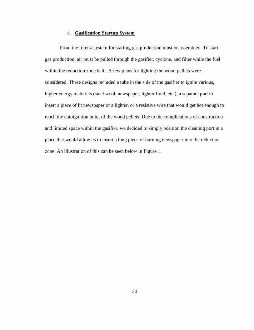
c. Gasification Startup System
From the filter a system for starting gas production must be assembled. To start
gas production, air must be pulled through the gasifier, cyclone, and filter while the fuel
within the reduction zone is lit. A few plans for lighting the wood pellets were
considered. These designs included a tube in the side of the gasifier to ignite various,
higher energy materials (steel wool, newspaper, lighter fluid, etc.), a separate port to
insert a piece of lit newspaper or a lighter, or a resistive wire that would get hot enough to
reach the autoignition point of the wood pellets. Due to the complications of construction
and limited space within the gasifier, we decided to simply position the cleaning port in a
place that would allow us to insert a long piece of burning newspaper into the reduction
zone. An illustration of this can be seen below in Figure 1.

21
To create suction through the system, various fans and blowers were considered
that would be attached to the filter unit. Ideas such as a D/C fan blowing through a
venturi, a D/C fan in line with the flow of fuel, and a heater blower in line with the flow
of fuel were all considered. For our system, we decided that a car air conditioner blower
would work best. This blower will be powered by a separate 12 volt battery that will be
mounted on the back of the lawn mower and will be activated by a switch. The starter
unit will be mounted to the side of the filter unit with a hose run from a ball valve
threaded into a tee attached to the filter to the inlet of the blower. A flume will be
attached to the outlet of the blower where gases can be lit to determine if gas production
Figure 1: Chosen method of lighting gasifier

22
has been started successfully. The layout of these components can be seen below in
Figure 2.
d. Fuel Delivery to Engine
To create the Air-Fuel Mixture (A/F mixture, AFM) that will be delivered to the
engine, a rudimentary carburetor for the Syngas must be built (SynCarb). Three designs
were considered to accomplish this. The first design included the removal and relocation
of the original gasoline carburetor and construction of a junction between gasoline carb.
and SynCarb. Due to the mounting system that is used by the original throttle linkage and
the lack of space to remount the original carburetor, this idea was rejected. The second
idea was to inject syngas into the existing air intake of the gasoline carburetor. This idea
Figure 2: Component layout on Syngas Filter. Flume, fan, and shutoff valve are shown at the
top of the diagram.

23
was also rejected because of limits in fuel delivery and the structural unreliability of the
injection port. This led to our third design, which was to remove the original air intake of
the gasoline carburetor, build an adapter flange to supply the Syngas AFM, and place a
shutoff valve in the gasoline line. This design allows us to swap between fuels at will and
maintain the original throttle controls (since the syngas mixture is being introduced
through the original gasoline carburetor). An illustration of this system can be found
below in Figure 1. For designs on the rejected ideas, reference Appendix III.

24
The Syncarb unit will also be mounted to the Syngas filter. It will require both
ball and butterfly valves, along with various junctions and hoses. A full list of
components can be found in the Bill of Materials in Appendix I.c.
Figure 1: Component layout on Syngas Filter. Carburetor components can been seen on the
bottom half of the diagram.
25
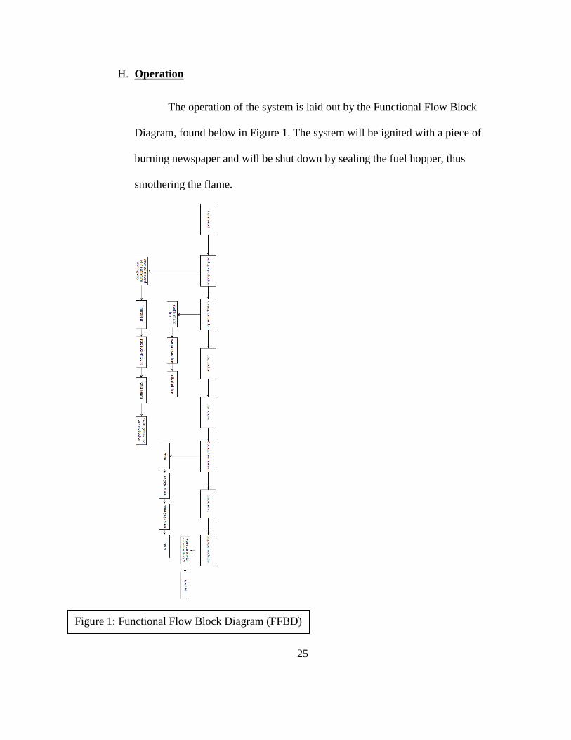
H. Operation
The operation of the system is laid out by the Functional Flow Block
Diagram, found below in Figure 1. The system will be ignited with a piece of
burning newspaper and will be shut down by sealing the fuel hopper, thus
smothering the flame.
Figure 1: Functional Flow Block Diagram (FFBD)
26
I. Cost Analysis
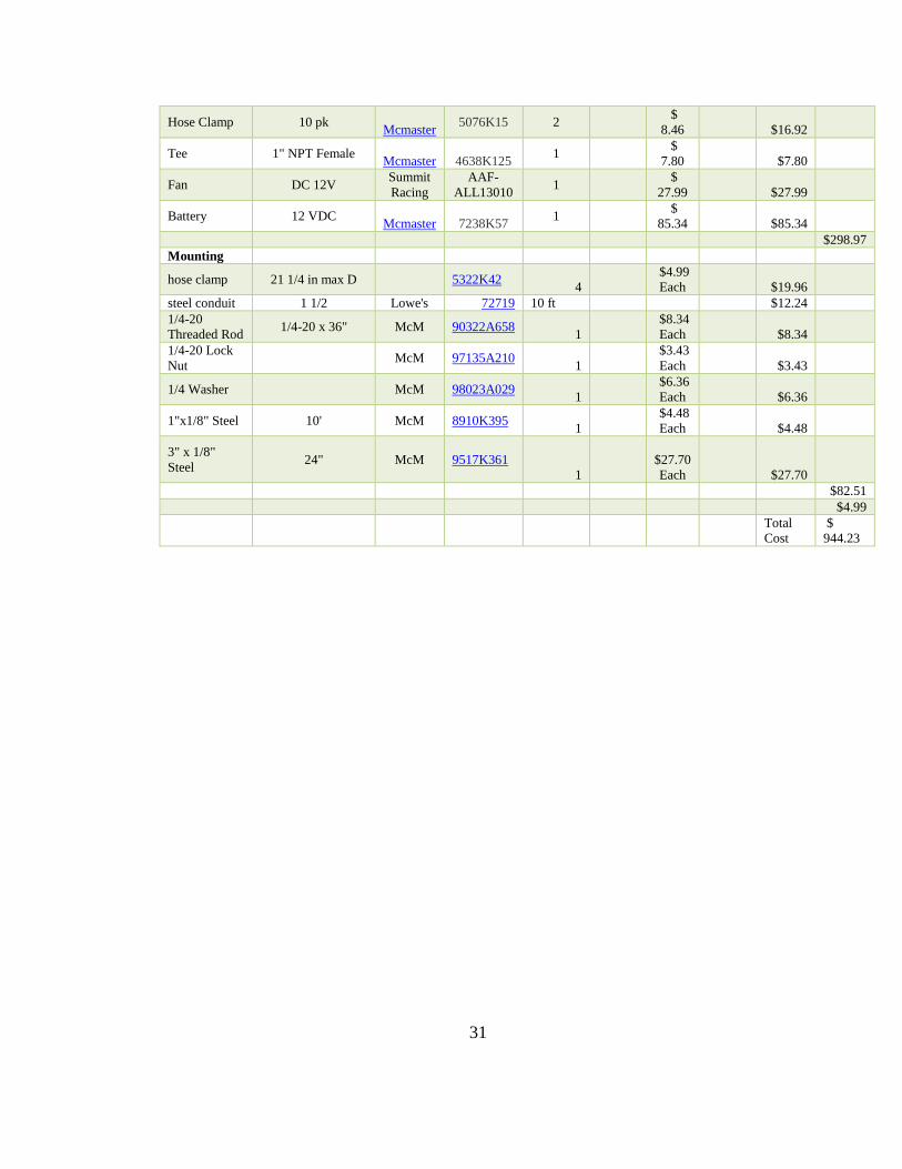
For this project, the team tried to limit the total cost of materials to $1000. Our
cost analysis shows that our system should cost us $900 to $950, however this includes
some parts we think we can source for free. In reality, our design would cost an estimated
$1000 if the few “free” components were sourced from a scrap yard. The Bill of
Materials listed in Appendix I.c gives a full break down of components and cost, as well
as vendors and their corresponding unit prices. We feel that some of the components
listed in the full BOM can be found cheaper at scrap yards, in waste stock from leftover
projects, or are items that team members may have available. By using these items, we
hope to reduce our overall cost to allow for room in the budget for incidental expenses.
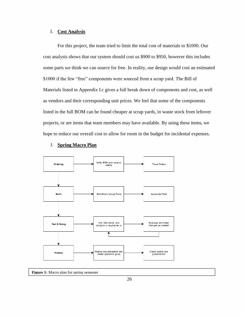
J. Spring Macro Plan
Figure 1: Macro plan for spring semester
27
The general plans for spring semester as laid out in the figure above begin with
finalizing and verifying our current BOM and placing orders for materials and parts we
need. From this point we can begin building and manufacturing parts as well as
assembling in the build phase. Once the machine is built, we move into the testing and
debugging phase. Once issues have been identified, fixed, and retested it is time to
finalize the documentation and finish the design. The project will culminate with a final
report and presentation during the final week of the spring semester.

28
Appendix
I. Project and Planning Documents
a. Fall 2016 Macro Plan

29
b. Spring 2017 Macro Plan
c. Cost Analysis and Bill of Materials
Name Description
Order
Site
Part
Number Quantity
Order
Status
Unit
Cost
Unit
Weight Cost Sums
Gasifier
silicon sleeve
insulation slide on Mcmaster 8829K88 1ft
$19.74
Each $19.74 stainless steel
colander scrap? $10.00 lightwieght
chains Mcmaster 3594T26 10 ft $17.30 connecting
links scrap ? 894j7T24
6 $1.97
Each $11.82 3 eyebolts scrap ? 9489T56 5 $8.01 4 in threaded
pipe section 4830K295
$26.72

30
steel plate lid 1/4 in scrap ? 1388K173 12" x 15" $101.52 pipe section
cap 4464K518
$79.36
6 in duct
5.89 in OD,
galvanized 1766K3
2 ft $8.28 6 in duct cap 6 in ID, galvanized 17135K93 $6.10 manometer
fitting Mcmaster 5670K86
2 $3.56
Each 7.12 manometer
fitting nuts Mcmaster 91862A306
4 $3.80
Each 15.2 manometer
tubing 1/4 in ID Mcmaster 5233K56 25
$0.24
Each $6.00
thermocouple
Inconeloverbraided,
K, high temp Omega
XCIB-K-1-
2-3 $39.00 16 gal drum 4115T83
$69.85
$426.02
Cleaning Cyclone Fire
extinquisher 1
$0.00
Each $0.00
18" of 2" pipe
2" x 18" Piple
Nipple Mcmaster 1
$24.06
Each $24.06 2" x 2"
Tubing Misc scrap Scrap 1
$0.00
Each $0.00
Flange 1
$0.00
Each $0.00
Filter
120mm
Ammo Can 1
$30.00
Each $30.00
Pipe Nipples 2" x 3" Pipe Nipple Mcmaster 7753K19 2
$6.34
Each $12.68 Filter Media Wood Pellets 1 $15 $15.00
Piping
6' of 2" ribbed
pipe Not sourced 1
$50.00
Each $50.00
$131.74
Startup/Carb
Wye 1" NPT Mcmaster
4638K324 1
$
22.10
$22.10 Butterfly
Valve 1" NPT
Mcmaster 9798K35 2
$
25.40
$50.80 2 End
Threaded
Pipe Nipple
1" NPT x 4" L
Mcmaster
7819K43 2
$
7.63
$15.26 Barbed Hose
Fitting 1" NPT
Mcmaster 5363K53 14
$
3.03
$42.42 Lightweight
Air Hose 1" ID, Grey
Mcmaster 5304K66 4
$
2.71
$10.84 1 End
Threaded
Pipe Nipple
1" NPT x 2" L
Mcmaster
7753K126 1
$
2.80
$2.80 Plain Carbon
Steel Plate 6"x6"x1/4"
Mcmaster 1388K104 1
$
16.70
$16.70
31
Hose Clamp 10 pk Mcmaster
5076K15 2
$
8.46
$16.92
Tee 1" NPT Female Mcmaster 4638K125
1
$
7.80
$7.80
Fan DC 12V Summit
Racing
AAF-
ALL13010 1
$
27.99
$27.99
Battery 12 VDC Mcmaster 7238K57
1
$
85.34
$85.34
$298.97
Mounting
hose clamp 21 1/4 in max D 5322K42
4
$4.99
Each
$19.96 steel conduit 1 1/2 Lowe's 72719 10 ft $12.24 1/4-20
Threaded Rod 1/4-20 x 36" McM 90322A658
1 $8.34
Each
$8.34 1/4-20 Lock
Nut McM 97135A210
1 $3.43
Each
$3.43
1/4 Washer McM 98023A029 1
$6.36
Each
$6.36
1"x1/8" Steel 10' McM 8910K395 1
$4.48
Each
$4.48
3" x 1/8"
Steel 24" McM 9517K361
1
$27.70
Each
$27.70
$82.51
$4.99
Total
Cost
$
944.23
32
II. Gasifier Materials
a. Pugh Matrix for overall gasifier design
Stratified Downdraft Imbert Downdraft
Weight 0 -2 Safety 0 -1 Ease of Maintenance
- Cleaning 0 -1 - Changing Parts 0 0
- Inspection 0 -1 Ease of Operation
- Refueling 0 -4 - Startup 0 0
- Shutdown 0 0 - Switch between fuels 0 0 Ease of Construction 0 -1
Totals 0 -10
b. FEMA Design

33
c. Preliminary gasifier designs
34

35
36

37

38
d. Gasifier Lid Concepts

39
e. Fire Tube Options
f. Fire Tube Selection Matrix
Decision
Matrix for
hearth/firetube
45 constriction 90 constriction straight pipe gas tank
ease of
fabrication
0 1 3 2
cost 0 1 2 3
weight 0 0 1 0
durability 0 0 0 0
efficiency 0 1 0 0
Totals 0 3 6 5

40
g. Mounting Concepts

41
h. Instrumentation

42
III. SynGas Delivery Materials
a. First Carburetor Design
b. Second Carburetor Design
This design would continue to a Tee junction that
would connect the SynCarb and gasoline
carburetor to the engine. This idea was abandoned
due to the positioning of these components on the
mower.

43
c. Third Carburetor Design
44
IV. Solidworks Models
a. Top View

45
b. Side View

46
c. Rear View
47
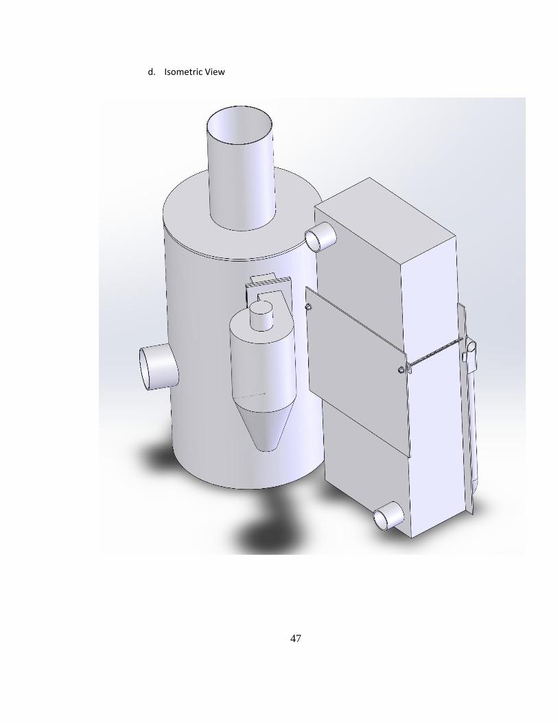
d. Isometric View

48
V. Component Block Diagrams
a. System Overview
b. Maintenance
c. Instrumentation

49
d. Documentation
e. Gasifier
f. Cyclone

50
g. Cooling
h. Filter
i. SynGas Carburetor