a13-0111: passive wireless sensing system for high ... · passive wireless sensing system for...
TRANSCRIPT

Passive Wireless Sensing System forHigh-Temperature Environments
Jeffrey. B. Friedlander, Eric Belknap, Eugene LeeSyntonics, LLC
Columbia, Maryland, USA
Lanlin Z. Lee, Eric WaltonThe ElectroScience Laboratory
The Ohio State UniversityColumbus, Ohio, USA
Abstract—Measurement of rotating components in cluttered,high-temperature jet engine environments is challenging forconventional wired sensors. We have developed a passive wirelesssensing (PaWS) system to measure strain, temperature, and otherparameters in high-temperature, harsh environments such asjet engines. PaWS utilizes piezoelectric surface acoustic wave(SAW) devices which are conformal, require no batteries, andcan operate at temperatures up to 300C. PaWS were fabricatedto operate at frequencies between 2.4 and 2.5 GHz and installedon test specimens representative of engine components. Thesespecimens underwent strain of over 4000 microstrain at ambientand elevated temperatures. A miniature patch antenna wasdeveloped to incorporate a package whose total dimensions aresmaller than 25x30x2 mm. An RF interrogation system (RFIS)was developed for simultaneous measurement of multiple sensors.Post-processing software has been developed to convert datafrom multiple sensors into calibrated strain values. Calibratedmeasurements were made with the RFIS using both wired andwireless methods in a laboratory and in a jet engine test cell.Sensor measurements correspond well with resitive strain gagecalibrations.
I. INTRODUCTION
Moving or rotating assemblies require strain, temperature,and other measurements to understand the operating conditionsof the system. Conventional sensors (e.g. resistive strain gages)fixed to the rotating bodies require wires routed through therotating equipment to slip rings on a shaft. A sophisticatedmeasurement configuration can consist of hundreds of delicateslip rings. A simpler, more robust method for in-situ measure-ments is desired. Much of this complexity can be eliminatedwith the passive wireless sensing (PaWS) system [1]. ThePaWS system consists of a SAW delay line and an antenna,comprising the sensor, and an RF data collection system.
SAW devices are energized by an incident RF signal,requiring no power supply, capacitive charge structure, orexternal circuits. Being passive, they readily lend themselves toapplications in harsh environments that would destroy conven-tional electronics. A SAW device consists of thin-film metallicfeatures on a piezoelectric substrate, namely an interdigitaltransducer (IDT) and reflectors. A representation of a SAWdevice is shown in Fig. 1. The ability of these SAW devicesto operate at temperatures up to 300C and their tolerancefor shock and vibration make them rugged enough for theharsh environment inside rotating machinery [2]. These low-profile sensors conform to the contours of the measurementsurfaces to avoid interfering with aerodynamics. An antenna
Fig. 1. A plan-view representation of a SAW delay line showing differentiallengths between reflectors.
must be co-located with one or more sensors to facilitate thewireless link. A rugged package must also protect the sensorfrom a harsh, high-temperature environment. SAW sensors canoperate for long periods, maintenance-free, providing valuabledata about the structural health of a system.
A wireless strain and temperature measurement systemhas been designed for the measurement of strain on rotatingmachines. Data collection is performed by the RF interrogationsystem (RFIS). The RFIS is designed to measure the phase-difference between two discrete reflections of a SAW sensor.Data processing software was developed to interpret this phasedifference and convert it to strain or temperature data.
Specialized SAW sensors have been designed and fabricatedin a cleanroom via electron-beam lithography. Time andfrequency-domain multiplexing facilitates the simultaneousmeasurement from multiple sensors. A patch antenna has beendesigned for the sensors communication link.
We have achieved wireless strain measurements on samplesrepresentative of jet engine components and compared them toa reference. The results of these measurements will be shown.
II. SAW DEVICE DESIGN
Passive wireless sensors are based on a SAW delay line.A SAW delay line relies on periodic metallic structures on apiezoelectric substrate to excite surface acoustic waves (SAW).There are two types of structures in the SAW delay line,an interdigital transducer (IDT) which converts an electricalsignal to a SAW and vice versa, and reflectors which reflectthe SAW back to the IDT after an acoustic propagation delay,see Fig. 1. Lithium niobate (LiNbO3) was selected as thepiezoelectric substrate for its low loss and ability to operateup to 300C [2].
182

TABLE ISAW TIME DELAY PARAMETERS FOR GIVEN FREQUENCY SLOT f
SAW ID Delay1 Reflector 1 Delay2 Reflector 2t1[µs] Spacing l1 [µm] t2 [µs] Spacing l2 [µm]
SAWf1 0.20 150 0.40 420SAWf2 0.60 700 0.80 980SAWf3 1.00 1250 1.20 1520SAWf4 1.40 1600 1.60 2065
TABLE IISAW FREQUENCY PARAMETERS (GHZ) FOR GIVEN TIME DELAY t
SAW ID Start StopFrequency Frequency
SAW1t 2.400 2.420SAW2t 2.420 2.447SAW3t 2.453 2.473SAW4t 2.480 2.500
A wireless sensor mounted to a moving object will havea varying RF path to its measurement hardware. The RFpropagation delay between a measurement system and thesensor is thus time-variant. Any change in sensor position willcreate errors in measuring the precise delay of SAW devicereflections. Each sensor needs a reference to which the strainedreflection can be compared. This is accomplished by usingtwo reflectors for each device. The two reflectors are placedon either side of the IDT to make use of the acoustic wavetraveling in both directions.
We can theoretically achieve simultaneous communicationwith at least 50 wireless sensors in the ISM band (2.4-2.5GHz), however the first generation of our system is de-signed for 16 sensors. A time-domain (TDM) and frequency-domain multiplexing (FDM) regime is integral to its design.Table 1 lists the delay parameters for four TDM sensors. Themaximum delay should not exceed 2µs because of increasingacoustic attenuation with delay [3]. There is the possibilityfor as many as 10 TDM delays within this limit when spacedcloser. For the preliminary system, 4 time delay sets wereimplemented. They are identified as SAWft where f denotesthe FDM slot and t denotes the TDM slot.
Four 20MHz channels were allocated evenly in the ISMband. The first generation SAW devices have a bandwidth ofapproximately 75MHz. The bandwidth of the SAW delay linecan be seen in Fig. 2 as the oscillating component of thefrequency response for two frequency slots. This oscillationcorresponds to the delayed reflections. A secondary resonanceis a result of the transmission-line pads discussed below.
The frequency ranges of our four channels can be seenin Table 2. Because the bandwidth of our first-generationSAW devices is greater than the channel width, we will usea narrowband antenna as a band-pass filter. There is room foran additional channel in this band, increasing the number ofpossible sensors to beyond 50.
Propagation studies of two aircraft engines were undertakento characterize the RF cutoff inside the compressor stages. Thiswork indicated the frequencies necessary for measurementincrease as the blade size in each subsequent stage of a turbine
engine decrease [3]. The ISM band used for this project issuitable for the fan and early compressor stages in a small jetengine [3].
Each sensor’s time delay occupies a unique time slot whichallows us to differentiate sensors and make simultaneousmeasurements at a given frequency. A superposition of threeimplemented delays (6 reflectors) can be seen in Fig. 3.
Fig. 2. Frequency-domain responses of multiple SAW sensors.
Fig. 3. Time-domain reflectometry of multiple SAW sensors.
A. SAW Device Fabrication
SAW sensors were fabricated at The Ohio State UniversityNanotech West Laboratory. The features on SAW devicesoperating at this frequency are smaller than conventionaloptical lithography methods will allow (critical dimension <400nm).
183
For future development, we chose a two-cycle fabricationprocess based on electron-beam lithography (EBL) for the sub-micron SAW features and photolithography for larger features.EBL is capable of critical dimension < 10nm in some casesand has the capability to easily reconfigure patterns withoutfabricating a new mask. Future sensors will be modified forthe higher cutoff frequencies required for the later compressorstages of jet engines (above 5.2 GHz). EBL will allow us toscale our features down to meet these requirements [3].
Larger objects on our SAW devices, such as wire-bondingpads and human-readable device identifiers, are too large tobe practical for EBL. The wire-bonding pads were designedas a coplanar strip transmission line running from the SAWIDT to the edge of the SAW device. The transmission linewas designed as an impedance transformer with a differentialimpedance (Zd = 69Ω) to match the capacitive IDT to a 50Ωantenna at the edge of the SAW device [4]. A protective coverfor the SAW device was constructed with layers of 100µmpolyamide.
The process was optimized on small 15 mm samples beforewe scaled fabrication to 100 mm diameter wafers for massproduction of SAW devices. Fig. 4 shows a wafer of lithiumniobate comprised of 60 TDM/FDM orthogonal SAW devicesbefore and after dicing.
Fig. 4. A wafer of 60 lithium niobate SAW devices before (left) and afterdicing (right).
B. SAW Sensor Antenna
To comprise a wireless sensor, the SAW delay line needsto be connected with an antenna for wireless communication.The sensor must have a small footprint and be low-profile. Thepackage should be low-profile to curved surfaces and mustnot cause localized stiffening of the substrate being measured.We fabricated rectangular patch antenna on Rogers TMM-10iceramic dielectric (εr = 9.8) to reduce the antenna dimensions[5]. We exploit the narrow-band nature of our antenna to actas a band-pass filter for the broader SAW devices [5]. Thisincreases isolation between channels.
The antenna was adhered adjacent to the SAW delay linewith a flexible epoxy to minimize its stiffening effect. Anotch was incorporated into the antenna substrate near its feedpoint to accommodate the SAW device. The patch antennawas electrically connected to the SAW device transmissionline with silver-based conductive epoxy. The dimensions for a
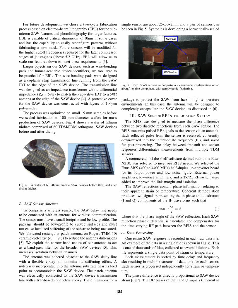
single sensor are about 25x30x2mm and a pair of sensors canbe seen in Fig. 5. Syntonics is developing a hermetically-sealed
Fig. 5. Two PaWS sensors in hoop-strain measurement configuration on anaircraft engine component with aerodynamic feathering.
package to protect the SAW from harsh, high-temperatureenvironments. In this case, the antenna will be designed tocompletely encapsulate the SAW device, as discussed in [6].
III. SAW SENSOR RF INTERROGATION SYSTEM
The RFIS was designed to measure the phase-differencebetween two discrete reflections from each SAW sensor. TheRFIS transmits pulsed RF signals to the sensor via an antenna.Each reflected pulse from the sensor is received, coherentlydown-mixed into the intermediate frequency (IF), and savedfor post-processing. The delay between transmit and sensorresponses differentiates measurements from multiple TDMsensors.
A commercial off the shelf software defined radio, the EttusN210, was selected to meet our RFIS needs. We selected theEttus SBX (400 to 4400 MHz) half-duplex up-converter boardfor its output power and low noise figure. External poweramplifiers, low-noise amplifiers, and a Tx/Rx RF switch wereadded to improve the link margin and isolation.
The SAW reflections contain phase information relating totheir apparent strain or temperature. Coherent demodulationproduces two signals representing the in-phase and quadrature(I and Q) components of the IF waveforms such that
tan−1 Q
I= φ (1)
where φ is the phase angle of the SAW reflection. Each SAWreflection phase differential is calculated and compensates forthe time-varying RF path between the RFIS and the sensor.
A. Data Processing
One entire SAW response is recorded in each raw data file.An example of the data in a single file is shown in Fig. 6. Thisis one of thousands of files, collected at several kilohertz. Eachfile represents a single data point of strain or temperature.
Each measurement is sorted by time delay and frequencyslot resulting in multiple streams of data, one for each sensor.Each sensor is processed independently for strain or tempera-ture.
The phase difference is directly proportional to SAW devicestrain [6][7]. The DC biases of the I and Q signals (inherent in
184

Fig. 6. Typical raw IF data from a single SAW sensor.
the RFIS) are first subtracted out for correct calculation of thephase angle. The phase angle is then computed via (1). Thisangle is unwrapped so that it can exceed a ±180 circularmeasurement. The unwrapped phase angles from the first andsecond reflector of each device are subtracted, resulting in thephase difference (∆φ).
IV. SENSOR STRAIN CALIBRATION
Strain (ε) is defined as elongation or compression (∆l)relative to original length (l)
ε =∆l
l. (2)
For a SAW delay line, we can relate reflector phase (φ) to theelongation of the SAW by
∆l =∆φv
2ωo(3)
where v is the acoustic propagation velocity of the SAWsubstrate and ωo is the angular interrogation frequency [6].Using (2), we can determine the strain on the surface of theSAW device as
εSAW =∆φ
2ωol. (4)
We relate our differential time delay (τ ) to l by the basicrelationship
τ =2∆l
v(5)
for round-trip reflections. Thus the strain for a half-SAWdevice is
εSAW =∆φ
ωoτ(6)
in agreement with [6] and [7].
A. Calibration TestingOur SAW sensors were calibrated to known strain values
to ensure accurate measurements. We developed specializedcalibration specimens fabricated from flat aluminum beamswith a SAW device co-located with one or more resistive straingages (RSG). Beams were bent in a four-point bending fixtureusing a hydraulic load frame while data was simultaneouslyrecorded from both the SAW device and the RSG. A four-point bend is superior to a traditional cantilever beam forcalibration due to the non-varying strain field within thealuminum specimen. This is caused by the constant bendingmoment in the beam between the two upper points of the bendfixture. The large area of constant strain field allows for a veryaccurate SAW device to RSG correlation by eliminating sensorplacement errors.
SAW device measurements were performed both wirelesslyand with a wired coaxial connection. Wired connections werepreferred during early development to minimize RF interfer-ence and improve signal-to-noise ratio. A close-up view of aSAW device and RSG on a bend specimen can be seen in Fig.7. The SAW device is connected to a U.FL connector jumperboard using conductive epoxy. During calibration testing, thiswas connected to an antenna or coaxial cable for wireless orwired measurement. Lithium niobate is a brittle ceramic and
Fig. 7. An aluminum bend specimen with a RSG and a SAW device withRF connector.
a SAW device can only withstand small amounts strain incomparison to an RSG. The strain needs to be transferred tothe SAW and measured in a reliable way to properly determinethe strain on a test article. This is done by selecting theproper adhesive. Various adhesives were evaluated for theirability to absorb strain and protect the SAW device from largemagnitudes of strain while also translating enough strain tomake accurate measurements.
It is not directly possible to measure the yield point ofaluminum (4000 microstrain) with a SAW that is rigidlybonded as SAW failure would occur. We chose an adhesivewith a strain transfer ratio (STR) that allowed the SAW to
185

remain intact after the yield point of aluminum has occurredand still maintain strain measurement resolution.
A calibration profile was mapped after extensive evaluationof various adhesives, both at room temperature and up to300C with our lithium niobate SAW devices. This calibrationprofile is empirical and enables accurate measurements of thestrain within the aluminum beam. We use the STR to scalethe SAW strain up to the aluminum strain. We can now plotthe results in terms of absolute strain, an example of whichcan be seen in Fig. 8. The strain measured with a SAW devicecorresponds well with the reference strain from the RSG.
Fig. 8. Comparing wirelessly measured SAW strain (blue dashed) and aresistive strain gage (red) for reference.
V. SENSOR TESTING ON ENGINE COMPONENTS
Syntonics has partnered with a major aircraft engine manu-facturer to instrument rotating engine components with PaWSsensors, see Fig. 5. PaWS will enable the engine design teamto verify their simulations as no other measurement methodexists. The instrumented assemblies rotate at speeds exceeding6000 RPM. Prior to the test, PaWS sensors were spun at high-speeds to prove the strength and integrity of the packagingunder such forces. PaWS hoop-strain sensors, installed on acommercial jet engine, endured hours of operation in a jetengine test cell while data was collected.
These ongoing efforts will enable Syntonics to evaluateand further improve our PaWS system. Future improvementsinclude increasing the number of sensors, increasing therange of measurement deeper inside the engine with higher-frequency devices, and improving sensor packaging. Syntonicsis pursuing the development of strain, temperature, and othermeasurement systems with industrial partners.
VI. CONCLUSION
Syntonics has developed PaWS, a wireless sensing systemis desired to measure strain, temperature, and other parameterson moving equipment such as jet engine components. PaWSprovides a wireless solution that can provide actionable data
without disrupting engine function. We have demonstratedPaWS feasibility in laboratory and industrial tests and haveshown excellent agreement between sensor data and calibratedreferences. Syntonics is also pursuing industrial measurementopportunities for its growing PaWS capabilities.
REFERENCES
[1] A. Pohl, ”Wirelessly Interrogable Surface Acoustic Wave Sensors forVehicular Applications,” IEEE Trans. Instrum. Meas, vol. 46, no. 4, pp.1031-1039, Aug. 1997.
[2] R. Fachberger, ”Applicability of LiNbO3, Langasite and GaPO4 in HighTemperature SAW Sensors Operating at Radio Frequencies,” IEEE Trans.Ultrason. Ferroelectr. Freq. Control, vol. 51, no. 11, pp. 1427-1431, Nov.2004.
[3] O. Tuncay, ”Wireless Strain Gauge System in a Multipath Environment,”M.S. thesis, Dept. Elect. and Comput. Eng., Ohio State Univ., Columbus,OH, 2008.
[4] K.C. Gupta et al., ”Coplanar Lines: Coplanar Waveguide and CoplanarStrip,” in Microstrip Lines and Slotlines, 2nd ed. Noorwood, MA: ArtechHouse, 1996, ch. 7, pp. 375-446.
[5] R. Garg et al., ”Rectangular Microstrip Antennas,” in Microstrip AntennaDesign Handbook. Noorwood, MA: Artech House, 2001, ch. 7, sec. 3,pp. 282-284.
[6] J. B. Friedlander, ”Wireless Strain Measurement with Surface AcousticWave Sensors,” M.S. thesis, Dept. Elect. and Comput. Eng., Ohio StateUniv., Columbus, OH, 2011.
[7] J. W. Gardner et al., ”IDT Microsensors,” in Microsensors, MEMS, andSmart Devices. Chichester, UK: Wiley, 2001, ch. 13, sec. 4, pp. 367-370.
186