a2.44 transformer intelligent condition monitoring...
TRANSCRIPT
Technical Brochure 630
GUIDE ON TRANSFORMER INTELLIGENT CONDITION MONITORING (TICM) SYSTEMS
CIGRE WG A2.44TUTORIAL
Convener: Carlos Dupont, Brazil
1

WG Members
• C. Dupont (BR) ‐ (Convener), TF Leaders: C. Beauchemin (CA), L. Cheim (US), N. Fantana (DE), C. Kane (US), R. Skrzypek (DE), J. Wetzer (NL), Editors: V. Catterson (UK), B. Sparling (CA).
• J. Borghetto (IT), P. Boss (CH), G. Buchgraber (AT), G. Buckley (AU), M. Bukvic (MK), T. Chiulan (RO), G. Csépes (HU), P. da Costa Silva (BR), R. da Fonte (BR), H. da Silva (BR), R. da Silva (BR), P. de Oliveira Turchiari (BR), A. de Pablo (ES), M. Foata (CA), W. Gil (PL), A. Gomes (BR), T. Gradnik (SI), E. Iraburu (ES), P. Jarman (UK), M. Jensen (DK), F. Johnsen (NO), M. Kadowaki (JP), S. Keitoue (HR), M. Koch (AT), A. Mcgrail (US), E. Mackenzie (UK), C. Moldoveanu (RO), K. Najdenkoski (MK), T. Noonan (IE), M. Paulino (BR), L. Peh (NZ), P. Picher (CA), G. Russell (AU), M. Ryadi (FR), T. Saha (AU), F. Scatiggio (IT), J. Silveira (BR), M. Soares (PT), I. Solteiro (BR), K. Takano (JP), J. Velek (CZ), K. Viereck (DE), A. Vita (BR).
2

Foreword
• The market now offers plenty of sensors, IEDs, on‐line continuous monitoring systems, analysis algorithms and software systems for condition evaluation
• CM use is growing in popularity.• There is no common practice on how to manage the whole process and convert the large amount of data into useful and relevant information.
• It is also understood that common ideas and designs would enable the construction of a Transformer Intelligent Condition Monitoring (TICM) System, flexible and extensible enough to meet utility needs now and in the future.
3
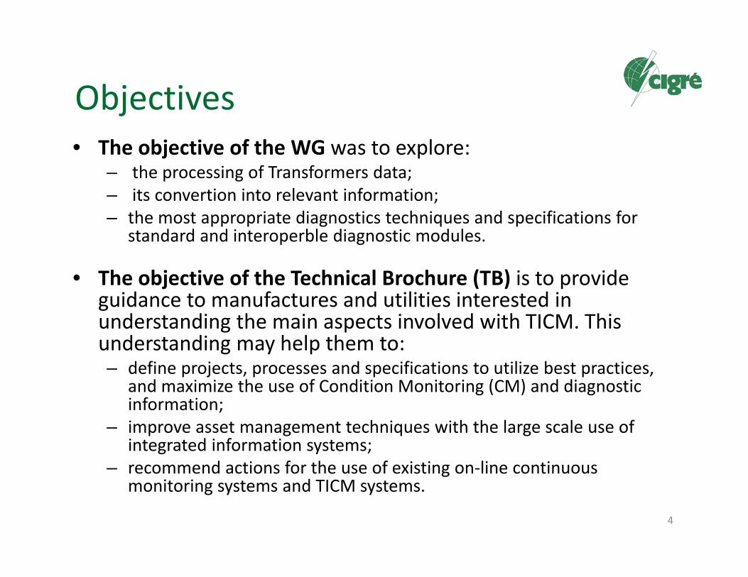
Objectives• The objective of the WG was to explore:
– the processing of Transformers data;– its convertion into relevant information; – the most appropriate diagnostics techniques and specifications for
standard and interoperble diagnostic modules.
• The objective of the Technical Brochure (TB) is to provide guidance to manufactures and utilities interested in understanding the main aspects involved with TICM. This understanding may help them to:– define projects, processes and specifications to utilize best practices,
and maximize the use of Condition Monitoring (CM) and diagnostic information;
– improve asset management techniques with the large scale use of integrated information systems;
– recommend actions for the use of existing on‐line continuous monitoring systems and TICM systems.
4

TB Table of Contents
• Chapter 1 – Introduction• Chapter 2 ‐ General Considerations• Chapter 3 – Functional Description• Chapter 4 – Intelligent Interpretation Methods• Chapter 5 ‐ Architecture• Chapter 6 – Data Specific Aspects• Chapter 7 – Strategic and Economic Aspects• Chapter 8 – Conclusion and Reccomendation• Bibliographic References• Annexes A, B, C, D, E
5

General Considerations
6
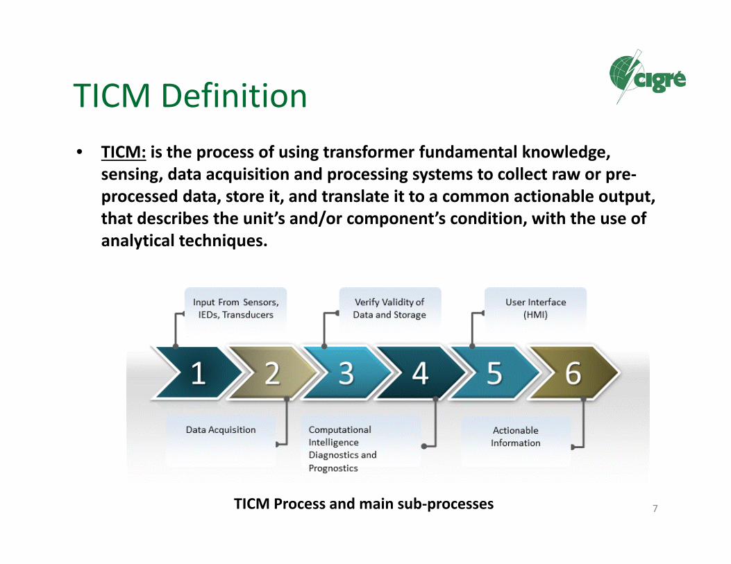
TICM Definition• TICM: is the process of using transformer fundamental knowledge,
sensing, data acquisition and processing systems to collect raw or pre‐processed data, store it, and translate it to a common actionable output, that describes the unit’s and/or component’s condition, with the use of analytical techniques.
7TICM Process and main sub‐processes

Equipment CM Positioning in theFuture Smart Grids
8
SmartGeneration
OffshoreWind Power
DistantSolar Power
DistributedEnergy Resources
Industrial &CommercialLoads
ResidentialLoads
E-Cars
SmartConsumption
E-Cars
Common Information Models and Communications Protocols
RELIABILITY AND EFFICIENCY PLANNING
MANAGED OPERATIONAL RELIABILITY RESOURCE OPTIMIZATION
Transmission Grid Distribution Grid
Decision Support System Integrity
Protection
AdvancedEnergy MgmtSystem (EMS)
AssetManagement
DistributionManagement
Systems (DMS)
Meter DataManagement
(MDM)
PLANNING & MODELINGBACKOFFICE / FRONT OFFICE
PowerElectronics
SubstationAutomation &
Protection
ConditionMonitoring
DistributionAutomation &
Protection
SmartMeters / Demand
Response
Smart Grid

User’s Needs Identification
• CIGRE Brochure 462 [1] edited in June 2011 by WG B3.12 –“Obtaining Value from On‐Line Substation Condition Monitoring”, presents the results of a survey performed with utilities around the world and has three interesting chapters called respectively:– “Present Practice” (chapter 9);– “Future Development” (chapter 10);– “Summary, Recommendations and Conclusions (chapter 11).
9

Some User’s Needs• A key factor for the future development of CM will be the
efforts in standardization for the development of a common language and understanding of function terminology– with naming and clarity of scope,– technical specification for parameters of the transformers to be
monitored, – rules for comparable interpretation ,– common presentation of the outcomes.
• A condition monitoring system in the future should have its functionalities described by a list of standard functions.– Each function should have an unique identification and should deliver
comparable results independendly of whoever is the manufacturer, allowing easy interoperability.
10

Some User’s Needs
• Efforts are necessary to “establish the base for an information exchange platform beyond the present exchange of information and unusual events between small numbers of users or manufacturers”.– Need for a wide and a common use solution
• The major issue comes from the software area where, according to TB 462: “consistently standardized designation of data collected from all different network places and the data linking to the company asset inventory data base is a need”.
11
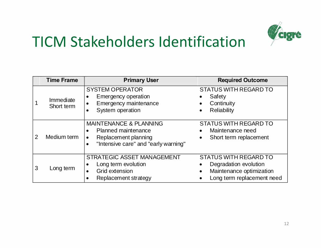
TICM Stakeholders Identification
12
Time Frame Primary User Required Outcome
1 Immediate Short term
SYSTEM OPERATOR Emergency operation Emergency maintenance System operation
STATUS WITH REGARD TO Safety Continuity Reliability
2 Medium term
MAINTENANCE & PLANNING Planned maintenance Replacement planning "Intensive care" and "early warning"
STATUS WITH REGARD TO Maintenance need Short term replacement
3 Long term
STRATEGIC ASSET MANAGEMENT Long term evolution Grid extension Replacement strategy
STATUS WITH REGARD TO Degradation evolution Maintenance optimization Long term replacement need

Functional Description of a TICM System
13

Different Stages in TICM
14

Basic TICM Process Stages
15
Basic data flowchart, defining the various processes, data types, storage types, presentation and reporting types

Processing Complexity
16
Level 1 Level 2 Level 3 Level 4
Sensor Physical Failure Requireddata property mode action
DECISION INPUT
Diversity of processing possibilities in transforming raw datainto decision information

TICM Generic Model
• “What is needed is a device which will answer the question: “What are the possible causes of the group of symptoms and signs I have elicited from my patient?” (F. NASH, 1954)
• Complex to reach, and not enough:– An intelligent system should also indicate appropriate actions !!
17

TICM Generic Model
18
“One of the most common reasons for failing IT related projects is that users start putting together the pieces without first agreeing a functional description with a robust and well documented model”.

The Concept of Functional Model
• In this report the FMEA is adapted to TICM, and involves the following consecutive steps:
– Breakdown of the transformer into functional subsystems– Defining the function of the primary subsystem– Define the possible functional failures of the primary subsystem– Define the (sub)components related to the functional failure– Define the failure modes and causes of the functional failure– Define the defect analysis name for the abnormal symptoms of
the failure modes– Define the on‐line measurable indicator values or data inputs for
each failure mode
19

Functions Levels
• Primary functionalities have a critical impact on the complete loss of functionality of the transformer as a whole, or the network it is part of. These functionalities need to be evaluated and monitored with high accuracy, and are mandatory to each functional TICM model;
• Secondary functionalities are not critical to the survival of the transformer or the network delivery but have a significant impact on the company business values. They may have an impact on quality of power delivery, costs, safety, environmental issues, and so on. Although many companies use comparable business values, the priorities and choices may differ, and the functional model should be able to accommodate that;
• Tertiary functionalities are not directly related to complete loss of functionality or significant harm to one or more business values. They may be incorporated according to the desires of the users and may be considered optional to TICM systems functionalities.
20

FMEA Example – Annex A
21
Oil Containment and Preservation– Table A.2
Cooling System– Table A.3
Active Part– Table A.1
OLTC– Table A.5
Bushings– Table A.4
Transformer Functional Main Subsystems
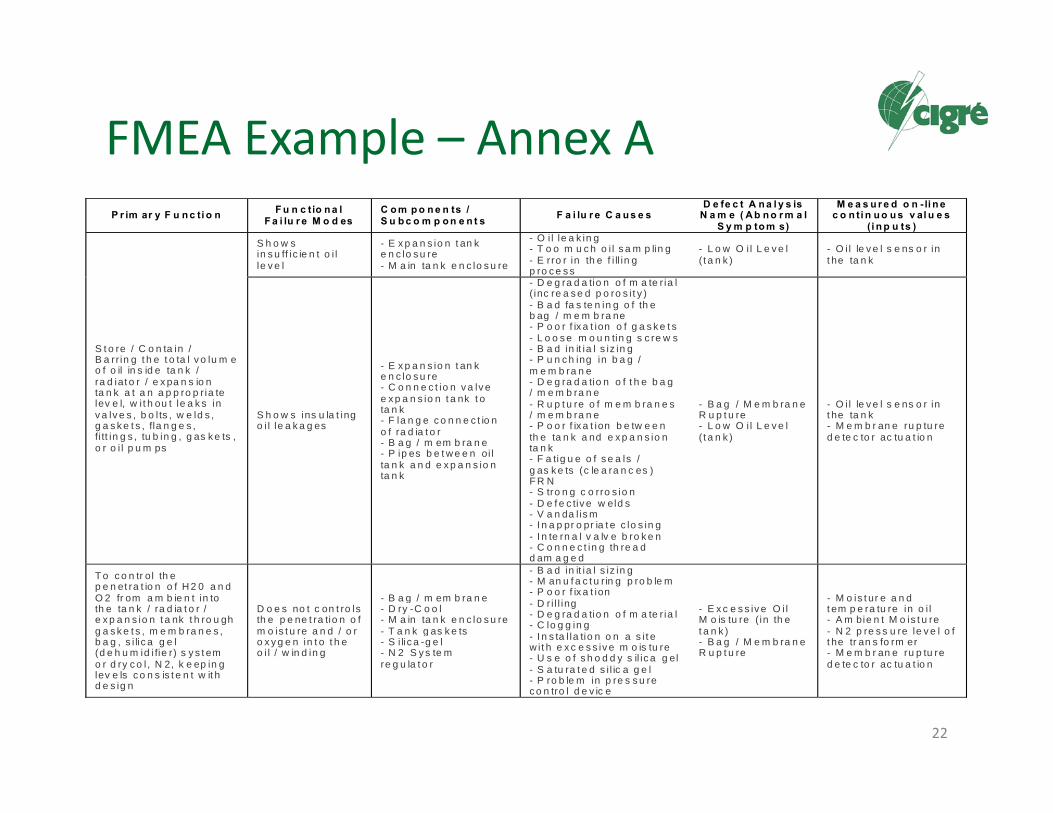
FMEA Example – Annex A
22
P r im ar y F u n c ti o n F u n c tio n a l F a i lu r e M o d es
C o m p o n e n ts / S u b c o m p o n e n t s F a i lu r e C a u s e s
D e fe c t A n a l y s is N a m e ( A b n o r m a l
S y m p to m s)
M e a s u r e d o n -li n e c o n ti n u o u s v al u e s
( i n p u ts )
S t o re / C o n ta in / B a rr in g t h e t o ta l v o lu m e o f o il in s id e ta n k / ra d iat o r / e x pa n s io n ta n k a t a n a p p ro p r ia te lev e l, w i t h ou t le a k s in v a lv e s , b o l ts , w e ld s , g a s k e t s , fla n g e s , fi tt in g s , tu b in g , g as k e ts , o r o i l p u m ps
S h o w s in s u ff ic ie n t o i l le v e l
- E x p a n s io n t an k e n c lo s u re - M a in ta n k e n c lo s u re
- O i l le a k in g- T o o m u c h o i l s a m p lin g - E rro r in th e f i ll in g p ro c e s s
- L o w O i l L e v e l ( t a n k )
- O i l le v e l s e ns o r in t he ta n k
S h o w s ins u la t ing o i l le a k a g es
- E x p a n s io n t an k e n c lo s u re - C o n n e c t io n v a lv e e x p a n s io n t a nk t o ta n k - F la n g e c o n n e c t io n o f ra d ia t o r - B a g / m em b ra n e - P ip es b e t w e e n oi l ta n k a n d e x p a n s io n ta n k
- D e g ra d a tio n o f m a te r ia l ( inc re a s e d p o ro s i t y ) - B a d fa s te n in g o f th e b ag / m e m b ra ne - P o o r f ix a t ion o f g a s k e t s - L o o s e m o u n tin g s c re w s - B a d in it ia l s iz in g - P u n c h ing in b a g / m e m b ra n e - D e g ra d a tio n o f t h e b a g / m e m b ra n e - R u p t u re o f m e m b ra n e s / m e m b ra n e - P o o r f ix a t ion b e tw e e n th e ta n k a nd e x p a n s io n ta n k - F a tig u e o f s e a ls / g as k e ts (c le a ra n c es ) F R N - S tro n g c o rro s io n - D e f e c tiv e w eld s - V a n da l is m - I n a p pr o pr ia t e c lo s in g - I n te rn a l v a lv e b ro k e n - C o n n e c t in g th re a d d am a g e d
- B a g / M e m b ra n e R u p t u re - L o w O i l L e v e l ( t a n k )
- O i l le v e l s e ns o r in t he ta n k - M e m b r an e ru p tu re d e te c to r ac tu a t io n
T o c o n tr ol th e p e n et ra t io n o f H 2 0 a n d O 2 fr om a m b ie n t in to th e ta n k / ra d ia t o r / e x p a n s io n t a nk t h ro u gh g a s k e t s , m e m b ra n e s , b a g , s i lic a g e l (d e h u m id i fie r) s y s t em o r d ry c o l , N 2, k e ep in g lev e ls c o n s is t e n t w it h d e s ig n
D o e s no t c on t ro ls th e p e ne t ra tio n o f m o is t u re a n d / o r o x y g e n in t o t h e o i l / w in d in g
- B a g / m em b ra n e - D ry -C o o l - M a in ta n k e n c lo s u re - T a n k g as k e ts - S i lic a -g e l - N 2 S y s te m re g u la t o r
- B a d in it ia l s iz in g - M an u f a c t u r in g p ro b le m - P o o r f ix a t ion - D r i l l ing - D e g ra d a tio n o f m a te r ia l- C lo g g in g - I n s ta l la tio n o n a s i t e w i t h e x c e s s iv e m o is tu re - U s e o f s h o d d y s il ic a g el - S a tu ra t e d s i l ic a g e l - P ro b le m in p re s s u re c o n tro l d e v ic e
- E x c e s s iv e O i l M o is tu re ( in th e t a n k ) - B a g / M e m b ra n e R u p t u re
- M o is t ur e a n d t em p e ra tu re in o i l - A m bie n t M o is t u re - N 2 p re s s u re le v e l o f t he tr an s fo rm er - M e m b r an e ru p tu re d e te c to r ac tu a t io n

FMEA Example – Annex A
23
Subsystem Measured on-line continuous values (inputs)
Active Part (Tab. A.1)
- Rate of change and total gas (primarily H2) dissolved in the oil - 8 gases dissolved in oil (single measurement) -Load current transformer (3 phases) - Core ground current -Short-circuit current of the transformer (disturbance of the 3 phases -Peak voltage of the transformer surge - Primary / secondary / tertiary voltages (3 phases) -Winding temperature (thermal imaging) -Top oil temperature -Moisture (and temperature) in oil tank - Membrane rupture detector actuation - Partial discharges measurement (electric, UHF, acoustic)
Oil Containment and Preservation (Tab. A.2)
- Oil level sensor in the tank - Membrane rupture detector actuation - Moisture and temperature in oil - Ambient Moisture - N2 pressure level of the transformer
Cooling (Tab. A.3)
- Oil pumps motor current- Cooling system AC supply voltage - Forced pumps oil flow - Status of the oil pumps (on / off) - Transformer (3 phases) load current - Fans motor current - Ambient temperature - Winding temperature (thermal imaging) - Top oil temperature - Bottom oil temperature - Cooling / Fans status (on / off)
Bushings (Tab. A.4) - Capacitance and tan-delta- Leakage current - Bushing voltage from capacitive coupler
OLTC (Tab. A.5)
- Status of the end of course (operation completion signal) - Actuation of command keys / buttonholes (event signal) - Motor driving current - Current accumulated in individual taps (load current) - Shaft torque curve of the engine switch (drive speed) - Tap position indicator - AC supply voltage - Number of accumulated changes on each tap - Total number of operations of the OLTC - RMS phase-to-earth transformer voltage (3 phases - primary / secondary / tertiary) - New position for the tap after switching (tap target) - OLTC Oil level - Oil temperature (diverter switch and compartment) - Gas sensor in insulating oil - Moisture content in the oil - Oil filter pressure - OLTC current (transformer winding)

FMEA Example – Annex A
24
Subsystem Analysis Code Defect Analysis Name
Active Part (Tab. A.1)
PTR_ARC - Electric Arc (in the tank)
PTR_PDS - Partial Discharges (in the tank)
PTR_COH - Conductor Overheating (in the tank)
PTR_EOM - Excessive Oil Moisture (in the tank)
PTR_WPD - Abnormal Winding Paper Degradation
Oil Containment and Preservation
(Tab. A.2)
PTR_LOL - Low Oil Level (in the tank)
PTR_BMR - Bag / Membrane Rupture
PTR_EOM - Excessive Oil Moisture (in the tank)
Cooling (Tab. A.3) PTR_RPF - Refusal of Oil Pump/Fans in Remote Command
PTR_ICA - Inefficient Cooling of Active Part
PTR_IOF - Inadequate Oil Flow Through the PumpsBushings (Tab. A.4) BSH_ISD - Insulation Deterioration (internal/external)
OLTC (Tab. A.5)
LTC_MDA - Motor Drive Mechanism Abnormality
LTC_AAO - Abnormal Automatic Operation
LTC_ITS - Inadequate Speed in Taps Switching
LTC_AEC - Abnormality in End of Course
LTC_AVR - Abnormal Voltage Regulation
LTC_LOL - Low Oil Level (in the OLTC)
LTC_EOM - Excessive Oil Moisture (in the OLTC)
LTC_ODD - Oil Dielectric Degradation
LTC_PDS - Partial Discharges (in OLTC)
LTC_IID - Internal Insulation Degradation
LTC_CCD - Contacts Cooking (diverter switch)
LTC_CCS - Contacts Cooking (selector/pre-selector)
LTC_ATI - Abnormality in Transition Impedance
LTC_OCT - Open Circuit
LTC_AOH - Abnormal Overheating (in the OLTC)

The Concept of Information Model
25
Concept of a TICM intelligent node, and an example structure

Common Output Definition
26
Schematic representation of condition development in time (top),and an example of condition coding (bottom)

Output Classification Scheme
27
COMPANY SPECIFIC
CLASS COLOR ACTION4 bad (faulty) replacement on short term3 poor (evolved defect) repair / replacement required2 average (early defect) observe evolution; diagnostic / repair action if required1 good (as good as new) business as usual
DEFINITION
UNIVERSAL
Proposed universal condition classification scheme (left), and an example of a possible company specific action classification scheme (right)
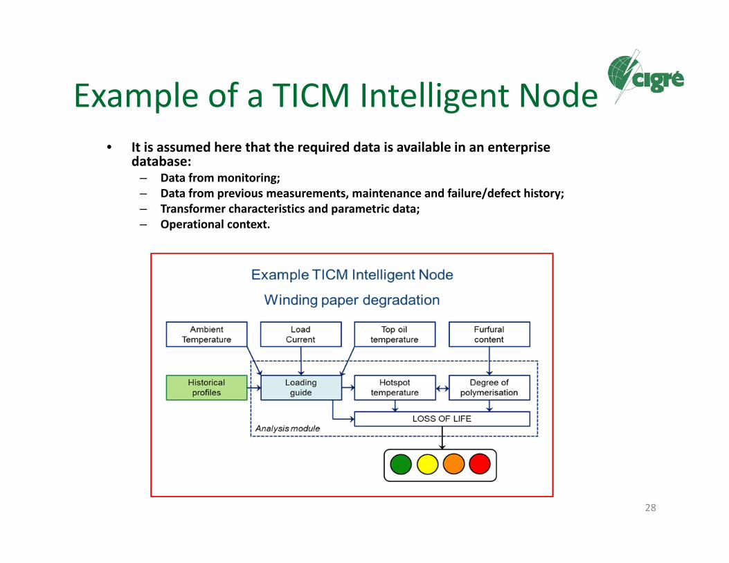
Example of a TICM Intelligent Node• It is assumed here that the required data is available in an enterprise
database:– Data from monitoring;– Data from previous measurements, maintenance and failure/defect history;– Transformer characteristics and parametric data;– Operational context.
28

Health and Risk Indexing• HI Definition: “one overall indicator describing the condition status of the
transformer that the decision maker can use to define and prioritize the required action, such as prioritization of replacement units, spares strategy definition, etc.”
• HI is on the scope of WG A2.49 (future brochure).
29

Intelligent Interpretation Methods
30
Techniques Classification
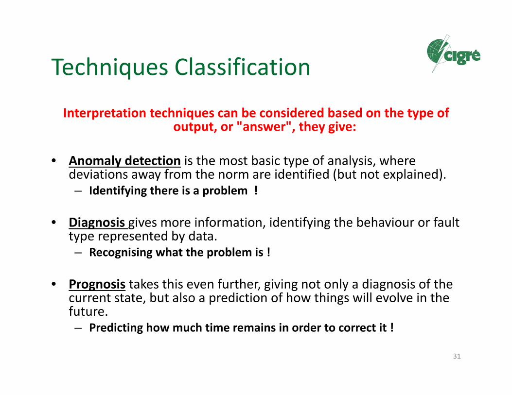
Interpretation techniques can be considered based on the type ofoutput, or "answer", they give:
• Anomaly detection is the most basic type of analysis, wheredeviations away from the norm are identified (but not explained).– Identifying there is a problem !
• Diagnosis gives more information, identifying the behaviour or faulttype represented by data. – Recognising what the problem is !
• Prognosis takes this even further, giving not only a diagnosis of thecurrent state, but also a prediction of how things will evolve in thefuture. – Predicting how much time remains in order to correct it !
31

Techniques Classification
There is a distinction between knowledge‐based and data‐driveninterpretation techniques, both in practical terms of how to implement and build a system and in the theoretical aim of
replicating intelligence:
• Knowledge‐based techniques, aim to encode the expert judgment of an engineer, and replicate the high‐level reasoning they would apply to a problem. – Examples include causal models, expert systems, and fuzzy logic.
• Data‐driven techniques, aim to encode lower level pattern matching facets of intelligence, and undergo training by repeated exposure to examples before any interpretation can be performed. – Examples include neural networks, multivariate analysis, rule
induction, and Bayesian networks.
32

Examples of Basic Algorithms Used for Transformer Monitoring
• Data Preparation and Pre‐processing– Data Cleaning ; Dimensionality Reduction; Data Transformation and Feature Extraction; Data Normalisation
• Derived Value (Causal Model)• Statistical Deviation• Trending
33

Example: Data Cleaning
34
Example of data cleaning by removing outliers
Outliers in data cause incorrectgrouping of points

Example: Data Transformation
35
Example of data transform from a time based signal to a frequency based value
A vibration signal from anOLTC evaluated bycontinuous wavelettransform

Example: Causal Model
36
RULES OUTPUT
• It is assumed that under significant load, the absolute water content in oil is uniform in the transformer
• The relative water content in the winding can be derived from the moisture sensor
• Paper-oil partition curves can be applied taking into account the time constant of water exchange with oil
Bubblingtemperature
Bubblingtemperature
SENSORS
Water content ininsulating paperWater content ininsulating paper
Watercondensationtemperature
Watercondensationtemperature
Absolute watercontent in oil
(ppm)
Absolute watercontent in oil
(ppm)
Moisture sensortemperature
Moisture sensor
Win
ding
hot
-spo
tte
mpe
ratu
re m
odelTop-oil temperature
H winding current
X winding current
Y winding current(optional)
(optional)
Water content inBarriers
Water content inBarriers
Example of a causal model: moisture in insulating system

Example: Statistic Deviation
37
Statistical description of relative voltage variation of bushing phase A (left) and change over time (from solid to dashed distributions)
Sample statistics for an abnormal voltage increase of 0.5% in phase A (dotted line) compared to normal population statistics (solid line)

Example: Trend Analysis
38
Dissolved Gas
0
20
40
60
80
100
120
140
160
180
200
2-Jul 16-Jul 30-Jul 13-Aug 27-Aug 10-Sep 24-Sep
Date
Gas
leve
l (μl
/l)
-10
-5
0
5
10
15
20
25
30
35
40
Gas
tren
d (μ
l/l)/p
erio
d
Gas level24 Hours trend30 Days trendTrend 0 Reference
Example of trend analysis on data from a gas‐in‐oil monitor collectedover a three month period

Examples of Advanced AlgorithmsUsed for Transformer Monitoring
• Fuzzy Logic• Multivariate Analysis• Neural Network• Expert System• Pattern Recognition/Classifiers• Others…
39
These algorithms more directly mimic the intelligence, reasoning, and
learning capabilities of an engineer
Example: Fuzzy Logic
40
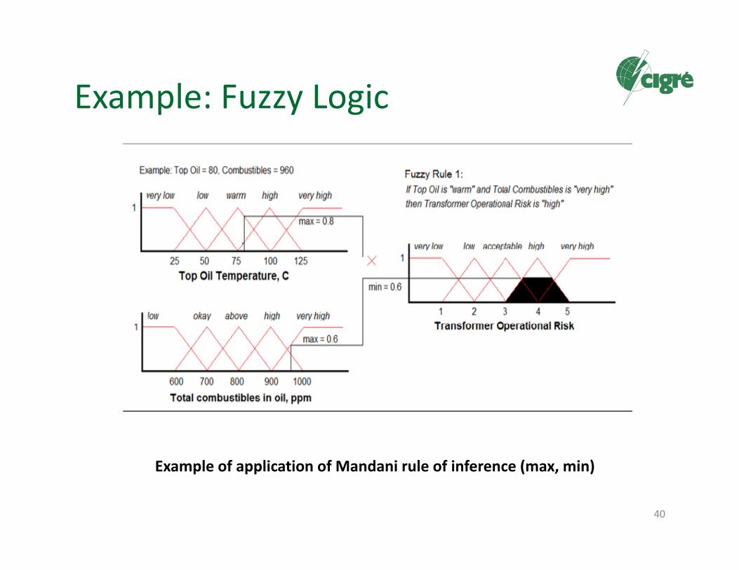
Example of application of Mandani rule of inference (max, min)

Example: Multivariate Analysis
41
Typical Correlated Transformer Variables Correlation Mapping

Example: Neural Network
42
Example of application of MLP (multi layer perceptron) neural network
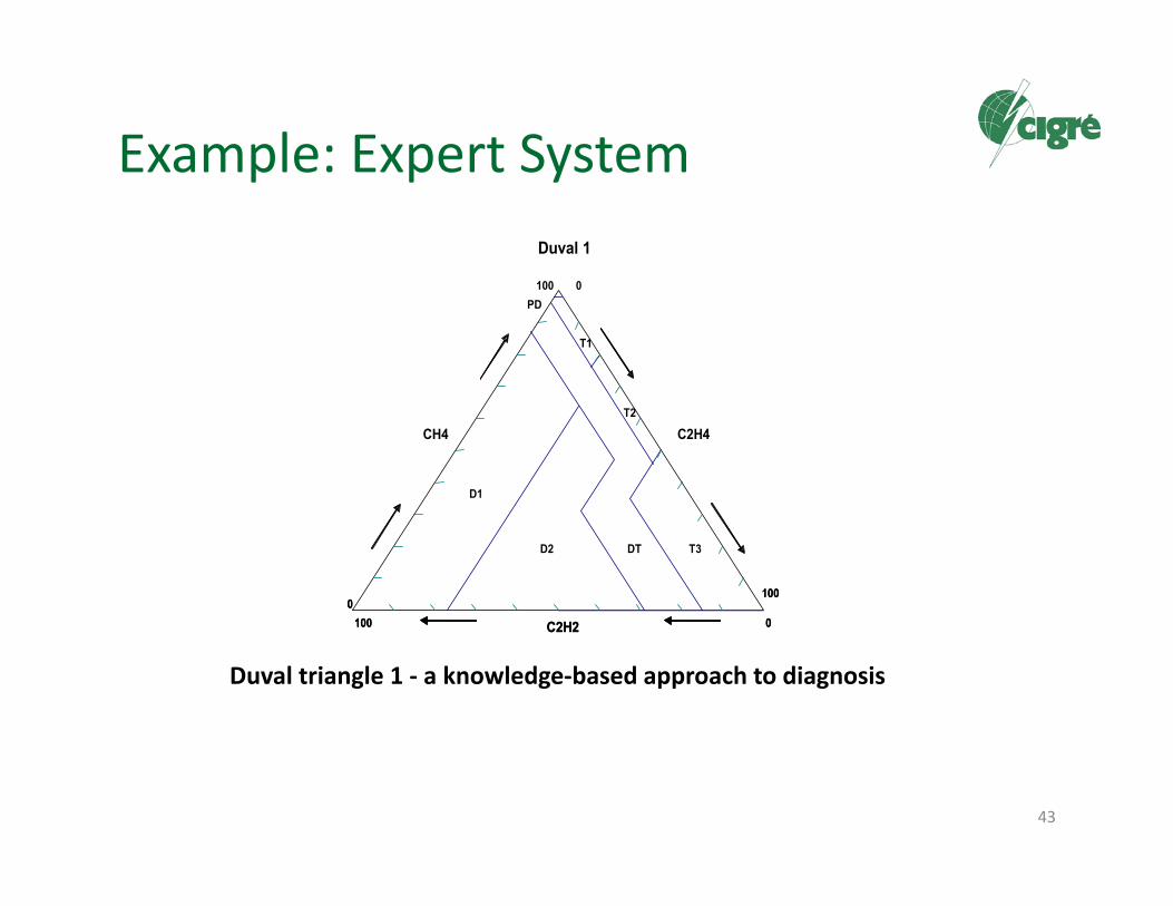
Example: Expert System
43
Duval triangle 1 ‐ a knowledge‐based approach to diagnosis
Duval 1
C2H2
CH4 C2H4
0
100 0
100
0100
D2
D1
DT
T1
T2
T3
PD
Duval 1
C2H2
CH4 C2H4
0
100 0
100
0100
D2
D1
DT
T1
T2
T3
PD

Example: Patern Recognitian/Classifiers
44
Example of a typical partial discharge pattern: Delaminating of theglue between winding and pressboard
TICM Architecture Description
45

Function‐based generic view of a TICM system
46

Architecture Alternatives
• 1) Single IED installed at the primary equipment or substation control level;
• 2) Set‐up of multiple networked IEDs and/or DAUs located at the substation level;
• 3) Configuration of various IEDs and/or DAUs connected to a monitoring server installed at the station level;
• 4) Combination of a single IED or a network of IEDs physically located at the transformer or within the substation with corporate server(s) data processing and storage server(s) providing complementary functions, (data management, analysis, and diagnosis based on on‐line and off‐line data of a transformer fleet);
47

48
Example of architecture with corporate monitoring server and database. Various system architectures: ‐ Ex. Station 1: One IED per transformer. ‐Ex. Station 2: Multiple IEDs connected to a monitoring server. ‐ Ex. station n: Several transformers monitored by one IED

Further Standardization of Data Management and Communication
• Less costly project engineering;• Lower installation and commissioning costs;• Reduced number of sensors and wiring costs;• Easier expandability;• Greater interoperability and interchangeability;• Improved maintainability;• Improved security.
The object‐oriented IEC 61850 data model enables the modelling of transformer monitoring functions that usually consists of different sub‐functions (free composition of data models algorithms as
described in Chapter 3).
49

50
Example of a system architecture based on IEC 61850

Data Specific Aspects
51
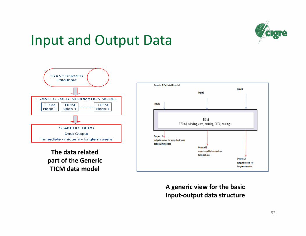
Input and Output Data
52
The data related part of the Generic TICM data model
A generic view for the basicInput‐output data structure
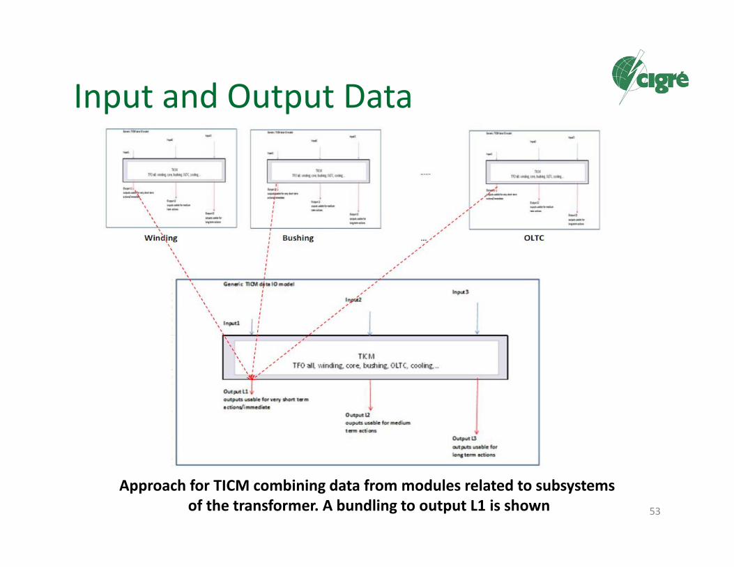
Input and Output Data
53
Approach for TICM combining data from modules related to subsystemsof the transformer. A bundling to output L1 is shown

Possibile Output Categories
• O_SafetyStatus: The output of the TICM system related to safety related status, which should assess all situations with a hazard or safety risk level.
• O_OperationCapability: The output of TICM should assess the operational capability of the transformer, especially loading capabilities and reserves.
• O_MaintenanceGeneralWarning: This output of TICM points to a recommended maintenance action in more general terms, i.e. where only approximate/general maintenance information is provided. This may include also self‐supervision alarms from IEDs.
• O_MaintenanceSpecificWarning: This output of TICM may assess a specific identified maintenance need knowing the exact part or subsystem to be maintained.
• O_AssetManagement: This type of output of the TICM system can support asset management actions and is intended to support rather long term decisions.
54

TICM May Use Different Input Data
– On‐Line Transformer Data From Sensors or IEDs• Data acquired on the transformer continuously on‐line (in service):• Data acquired in SCADA systems continuously on‐line:• Data stored in protection relays and fault recorders during unexpected events on‐line (if the
utility policy allows its use):• Data acquired or computed by other devices or systems in the network:
– Data From Utility Information Systems• Data registered in the asset inventory• Data coming from service history – events, relocations, changes in service conditions• Data collected during maintenance or diagnostic works on a transformer• Data coming from diagnosis and testing activities• Data about transformer criticality or importance• Data coming from nameplate data of the transformer
– Other Usable Data• Data acquired on the energized transformer not continuously• Data acquired on the de‐energized transformer not continuously• Data from special models and expert systems
55

Example ‐ Data Input Overview
56

Remark to Data Quality and Input Validation
• Performance of the TICM is only as good as the input data used is.– Therefore it is very important to use only verified and validated data.
– The verification and validation process may be specific for each type of data and may differ according to where data is coming from (sensors, other substation systems, utility information systems).
57

Data for TICM and Standardization
• On Going Work:– Activities related to communication, protocols and data and
message exchange:• IEC 61850; DNP 3.0; Modbus; IEC 60870‐5 ‐101, 102, 103, 104; IEC 61850‐90‐3, ‐ Using IEC 61850 for condition monitoring and analysis
– Activities related to transformer itself, e.g. on monitoring, or sensors:
• IEC 60076‐7, Loading guide for oil immersed power transformers • IEEE C57.143 2012, Guide for application of monitoring to liquid immersed TFO and components
• IEEE C57.91, IEEE guide for loading of mineral oil immersed transformers
– Data related to network and network devices in general.• IEC 61970, CIM; IEC 61499 open standard for distributed control and automation; COMTRADE latest standard 2013 release
58

Using IEC 61850 for ConditionMonitoring Diagnosis and Analysis
59Structure of an IEC 61850 Data Model

Using IEC 61850 for ConditionMonitoring Diagnosis and Analysis
60
EXAMPLE OF
Logical Nodes (LN) for Transformer
Monitoring related to the actual standard of IEC 61850‐90‐3 and IEC 61850‐7‐4
ed. 2

Strategic and Economic Aspects
61
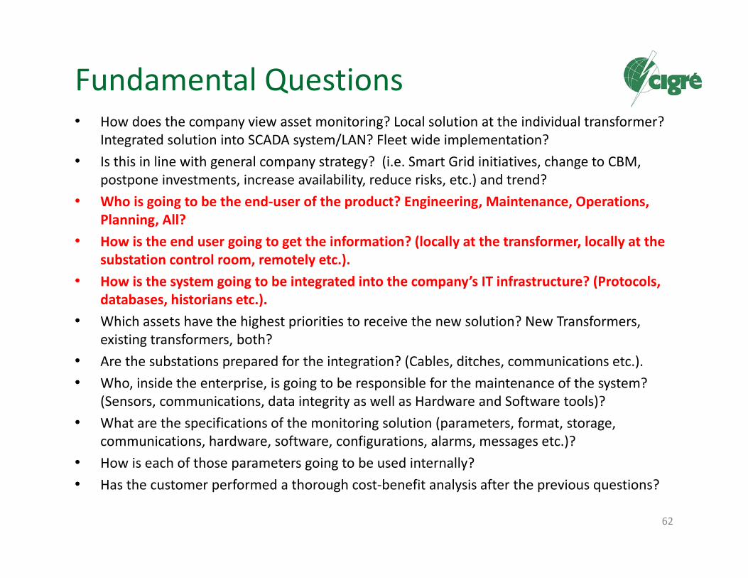
Fundamental Questions• How does the company view asset monitoring? Local solution at the individual transformer?
Integrated solution into SCADA system/LAN? Fleet wide implementation?• Is this in line with general company strategy? (i.e. Smart Grid initiatives, change to CBM,
postpone investments, increase availability, reduce risks, etc.) and trend?• Who is going to be the end‐user of the product? Engineering, Maintenance, Operations,
Planning, All?• How is the end user going to get the information? (locally at the transformer, locally at the
substation control room, remotely etc.).• How is the system going to be integrated into the company’s IT infrastructure? (Protocols,
databases, historians etc.).• Which assets have the highest priorities to receive the new solution? New Transformers,
existing transformers, both?• Are the substations prepared for the integration? (Cables, ditches, communications etc.).• Who, inside the enterprise, is going to be responsible for the maintenance of the system?
(Sensors, communications, data integrity as well as Hardware and Software tools)?• What are the specifications of the monitoring solution (parameters, format, storage,
communications, hardware, software, configurations, alarms, messages etc.)?• How is each of those parameters going to be used internally?• Has the customer performed a thorough cost‐benefit analysis after the previous questions?
62
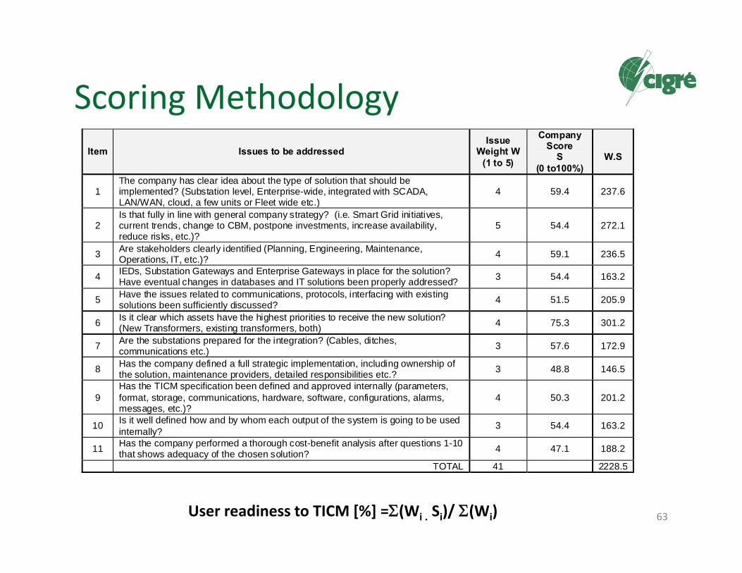
Scoring Methodology
63
Item Issues to be addressed Issue
Weight W (1 to 5)
Company Score
S (0 to100%)
W.S
1 The company has clear idea about the type of solution that should be implemented? (Substation level, Enterprise-wide, integrated with SCADA, LAN/WAN, cloud, a few units or Fleet wide etc.)
4 59.4 237.6
2 Is that fully in line with general company strategy? (i.e. Smart Grid initiatives, current trends, change to CBM, postpone investments, increase availability, reduce risks, etc.)?
5 54.4 272.1
3 Are stakeholders clearly identified (Planning, Engineering, Maintenance, Operations, IT, etc.)? 4 59.1 236.5
4 IEDs, Substation Gateways and Enterprise Gateways in place for the solution? Have eventual changes in databases and IT solutions been properly addressed? 3 54.4 163.2
5 Have the issues related to communications, protocols, interfacing with existing solutions been sufficiently discussed? 4 51.5 205.9
6 Is it clear which assets have the highest priorities to receive the new solution? (New Transformers, existing transformers, both) 4 75.3 301.2
7 Are the substations prepared for the integration? (Cables, ditches, communications etc.) 3 57.6 172.9
8 Has the company defined a full strategic implementation, including ownership of the solution, maintenance providers, detailed responsibilities etc.? 3 48.8 146.5
9 Has the TICM specification been defined and approved internally (parameters, format, storage, communications, hardware, software, configurations, alarms, messages, etc.)?
4 50.3 201.2
10 Is it well defined how and by whom each output of the system is going to be used internally? 3 54.4 163.2
11 Has the company performed a thorough cost-benefit analysis after questions 1-10 that shows adequacy of the chosen solution? 4 47.1 188.2
TOTAL 41 2228.5
User readiness to TICM [%] =(Wi . Si)/ (Wi)

User readiness to TICM
64
User readiness (%) Evaluation Recommendation
0-25 Very weak situationThe company is not prepared yet to adequately deploy and maintain TICM systems
26-50 WeakCompany shows several weaknesses which may impact negatively full deployment of TICM
51-65 Some weakness
Company may deploy TICM but will certainly have to fix several internal issues simultaneously to take full advantage of TICM.
66-85 Strong
Company may certainly deploy TICM but will eventually have to fix several internal issues simultaneously to take full advantage of TICM.
>85 Very strongCompany is already in a very strong position to deploy and take full advantage of TICM.
User readiness to TICM [%] =(Wi . Si)/ (Wi)

User companies readiness, according to the results of the internal WG survey
65
0
10
20
30
40
50
60
70
80
90
1 2 3 4 5 6 7 8 9 10 11 12 13 14 15 16 17
WG Members (17) Application of methodology in Table 7.1
My
com
pany
read
ines
s, %
Member i.d.
in a general approach, the readiness of companies is in “some weakness” evaluation (readiness to TICM = 55.82%). This in a qualitative way shows that TICM concepts still need further work inside the companies before to become a real valuable solution, helps to explain some of the nowadays considered unsuccessful results associated to monitoring, and, is useful for benchmarking

Conclusion and Reccomendation
66

Conclusion and Reccomendation (1)
• It may be concluded that a TICM system’s successful technological implementation and integration into a company’s processes depends on particular challenges:
• The user’s first challenge is to define which are the important transformer functions and defects they want to have considered in the TICM system, together with the associated analysis that should be performed to try to maintain, in a proactive manner, the transformer’s health, its longevity and low risk of failure. – The chosen analysis algorithms and methods could be developed in‐
house or contracted from external development sources, but should be specified to allow a standard interface and modular implementation (even by different providers) and an adequate functionality commissioning.
67

Conclusion and Reccomendation (2)
• Secondly, for the long term success of TICM systems, the users have to be sure that their companies are prepared to work within the new reality of intelligent systems and that these systems will be adequately maintained and periodically updated to take advantage of the new and evolving technology. – Companies should prepare to incorporate condition
monitoring into their processes.– Instructions for use and maintenance for completely new or
extended systems have to be prepared before such an application can be installed.
– It is important to provide a high level of staff training and carefully plan each step to be taken.
68
Conclusion and Reccomendation (3)
• From the point of view of solution suppliers, the challenge is to develop reliable, standardized, open and modular tools able to meet the specifications of the users, as well as help users of devices for continuous monitoring to obtain high availability and good return on investment of such equipment. – The TICM generic model developed in Chapter 3 and Annex A
example could be used in the development process of such tools.
• Further CIGRE work in TICM should be directed towards IEC groups that are developing Condition Monitoring and Diagnosis as logical nodes for the next IEC 61850 versions.
69

70