a4tit intorq v30 · intorq bfk468 j setting the standard operating instructions spring-applied...
TRANSCRIPT

INTORQ BFK468
j
setting the standard
Operating Instructions
www.intorq.com
Spring-applied brake with electromagnetic release

j | BA 14.0190 | 11/2013
2
This documentation applies to ...
BFK468
BFK46825-002.iso/dms
Product key
Product key INTORQ B FK -
Legend for INTORQ BFK468 product key Product group Brakes
Product family Spring-applied brake
Type 468
Size 18, 20, 25, 31
Design E - adjustable (brake torque can be reduced via adjuster nut)N - not adjustable
Not coded: Supply voltage, hub bore, options

j | BA 14.0190 | 11/2013
i
3
Identification
Package label Example
Manufacturer Bar code
Type (see product key) Type No.
Name Rated torque Quantity per box
Release/holding voltage Release/holding power Packing date
Additional information CE designationBFK458-002.iso/dms
Nameplate Example
Manufacturer CE designation
Type (see product key)
Release/holding voltage Release/holding power Hub diameter
Type No. Rated torque Production dateBFK468-001.iso/dms
Document history
Material number Version Description
13190474 1.0 01/2007 TD09 First edition
33002357 2.0 11/2012 TD09 Complete revision
33002357 3.0 11/2013 TD09 Changed tightening torques of fixing screws, 160Fig. 0Tab. 0

Contentsi
j | BA 14.0190 | 11/2013
4
1 Preface and general information 5. . . . . . . . . . . . . . . . . . . . . . . . . . . . . . . . . . . . . . .
1.1 About these Operating Instructions 5. . . . . . . . . . . . . . . . . . . . . . . . . . . . . . . . . . .
1.2 Terminology used 5. . . . . . . . . . . . . . . . . . . . . . . . . . . . . . . . . . . . . . . . . . . . . . . . .
1.3 Conventions used 5. . . . . . . . . . . . . . . . . . . . . . . . . . . . . . . . . . . . . . . . . . . . . . . . .
1.4 Abbreviations used 6. . . . . . . . . . . . . . . . . . . . . . . . . . . . . . . . . . . . . . . . . . . . . . . .
1.5 Notes used 7. . . . . . . . . . . . . . . . . . . . . . . . . . . . . . . . . . . . . . . . . . . . . . . . . . . . . .
1.6 Scope of supply 8. . . . . . . . . . . . . . . . . . . . . . . . . . . . . . . . . . . . . . . . . . . . . . . . . .
1.7 Disposal 8. . . . . . . . . . . . . . . . . . . . . . . . . . . . . . . . . . . . . . . . . . . . . . . . . . . . . . . .
1.8 Drive systems 8. . . . . . . . . . . . . . . . . . . . . . . . . . . . . . . . . . . . . . . . . . . . . . . . . . . .
1.9 Legal regulations 9. . . . . . . . . . . . . . . . . . . . . . . . . . . . . . . . . . . . . . . . . . . . . . . . .
2 Safety instructions 10. . . . . . . . . . . . . . . . . . . . . . . . . . . . . . . . . . . . . . . . . . . . . . . . . . .
2.1 General safety information 10. . . . . . . . . . . . . . . . . . . . . . . . . . . . . . . . . . . . . . . . . .
2.2 Application as directed 11. . . . . . . . . . . . . . . . . . . . . . . . . . . . . . . . . . . . . . . . . . . .
3 Technical data 12. . . . . . . . . . . . . . . . . . . . . . . . . . . . . . . . . . . . . . . . . . . . . . . . . . . . . . .
3.1 Product description 12. . . . . . . . . . . . . . . . . . . . . . . . . . . . . . . . . . . . . . . . . . . . . . .
3.2 Brake torques 15. . . . . . . . . . . . . . . . . . . . . . . . . . . . . . . . . . . . . . . . . . . . . . . . . . .
3.3 Characteristics 16. . . . . . . . . . . . . . . . . . . . . . . . . . . . . . . . . . . . . . . . . . . . . . . . . .
3.4 Operating times 18. . . . . . . . . . . . . . . . . . . . . . . . . . . . . . . . . . . . . . . . . . . . . . . . . .
3.5 Friction work / operating frequency 19. . . . . . . . . . . . . . . . . . . . . . . . . . . . . . . . . .
3.6 Emission 20. . . . . . . . . . . . . . . . . . . . . . . . . . . . . . . . . . . . . . . . . . . . . . . . . . . . . . .
4 Mechanical installation 21. . . . . . . . . . . . . . . . . . . . . . . . . . . . . . . . . . . . . . . . . . . . . . . .
4.1 Necessary tools 21. . . . . . . . . . . . . . . . . . . . . . . . . . . . . . . . . . . . . . . . . . . . . . . . . .
4.2 Mounting 22. . . . . . . . . . . . . . . . . . . . . . . . . . . . . . . . . . . . . . . . . . . . . . . . . . . . . . .
4.3 Installation 22. . . . . . . . . . . . . . . . . . . . . . . . . . . . . . . . . . . . . . . . . . . . . . . . . . . . . .
5 Electrical installation 29. . . . . . . . . . . . . . . . . . . . . . . . . . . . . . . . . . . . . . . . . . . . . . . . .
5.1 Bridge/half-wave rectifiers (option) 29. . . . . . . . . . . . . . . . . . . . . . . . . . . . . . . . . . .
5.2 Electrical connection 31. . . . . . . . . . . . . . . . . . . . . . . . . . . . . . . . . . . . . . . . . . . . . .
6 Commissioning and operation 34. . . . . . . . . . . . . . . . . . . . . . . . . . . . . . . . . . . . . . . . . .
6.1 Functional test 34. . . . . . . . . . . . . . . . . . . . . . . . . . . . . . . . . . . . . . . . . . . . . . . . . . .
6.2 Reducing the brake torque 37. . . . . . . . . . . . . . . . . . . . . . . . . . . . . . . . . . . . . . . . .
6.3 During operation 38. . . . . . . . . . . . . . . . . . . . . . . . . . . . . . . . . . . . . . . . . . . . . . . . .
7 Maintenance/repair 39. . . . . . . . . . . . . . . . . . . . . . . . . . . . . . . . . . . . . . . . . . . . . . . . . .
7.1 Wear of spring-applied brakes 39. . . . . . . . . . . . . . . . . . . . . . . . . . . . . . . . . . . . . . .
7.2 Inspections 40. . . . . . . . . . . . . . . . . . . . . . . . . . . . . . . . . . . . . . . . . . . . . . . . . . . . . .
7.3 Maintenance operations 41. . . . . . . . . . . . . . . . . . . . . . . . . . . . . . . . . . . . . . . . . . . .
7.4 Spare-parts list 43. . . . . . . . . . . . . . . . . . . . . . . . . . . . . . . . . . . . . . . . . . . . . . . . . .
7.5 Spare parts order 44. . . . . . . . . . . . . . . . . . . . . . . . . . . . . . . . . . . . . . . . . . . . . . . .
8 Troubleshooting and fault elimination 45. . . . . . . . . . . . . . . . . . . . . . . . . . . . . . . . . . .

Preface and general information1 i
j | BA 14.0190 | 11/2013
5
1 Preface and general information
1.1 About these Operating Instructions
| These Operating Instructions will help you to work safely on and with thespring-applied brake with electromagnetic release. They contain safety instructionsthat must be followed.
| All persons working on or with the electromagnetically released spring-applied brakesmust have the Operating Instructions available and observe the information and notesrelevant for them.
| The Operating Instructions must always be in a complete and perfectly readablecondition.
1.2 Terminology used
Term In the following text used for
Spring-applied brake Spring-applied brake with electromagnetic release
Drive system Drive systems with spring-applied brakes and other drivecomponents
1.3 Conventions used
This documentation uses the following conventions to distinguish different types ofinformation:
Numeric notation Decimal separator Point The decimal point is always used.For example: 1234.56
Symbols Page reference Reference to another page with additional informationFor example: 16 = see page 16
Document reference Reference to another documentation with additionalinformationFor example: Operating instructions
Wildcard Wildcard for options, selectionsFor example: BFK458- = BFK458-10
Preface and general information1
j | BA 14.0190 | 11/2013
6
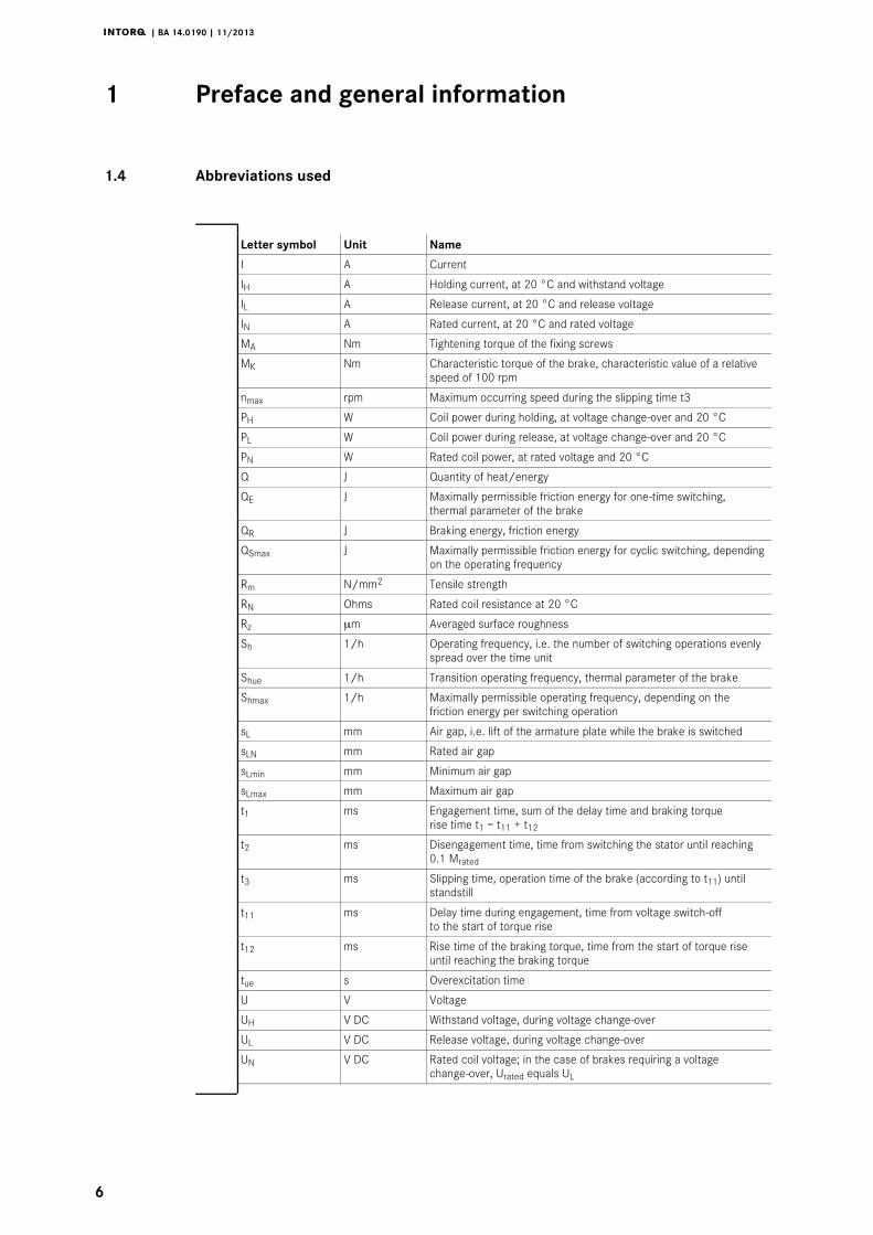
1.4 Abbreviations used
Letter symbol Unit Name
I A Current
IH A Holding current, at 20 °C and withstand voltage
IL A Release current, at 20 °C and release voltage
IN A Rated current, at 20 °C and rated voltage
MA Nm Tightening torque of the fixing screws
MK Nm Characteristic torque of the brake, characteristic value of a relativespeed of 100 rpm
nmax rpm Maximum occurring speed during the slipping time t3
PH W Coil power during holding, at voltage change-over and 20 °C
PL W Coil power during release, at voltage change-over and 20 °C
PN W Rated coil power, at rated voltage and 20 °C
Q J Quantity of heat/energy
QE J Maximally permissible friction energy for one-time switching,thermal parameter of the brake
QR J Braking energy, friction energy
QSmax J Maximally permissible friction energy for cyclic switching, dependingon the operating frequency
Rm N/mm2 Tensile strength
RN Ohms Rated coil resistance at 20 °C
Rz μm Averaged surface roughness
Sh 1/h Operating frequency, i.e. the number of switching operations evenlyspread over the time unit
Shue 1/h Transition operating frequency, thermal parameter of the brake
Shmax 1/h Maximally permissible operating frequency, depending on thefriction energy per switching operation
sL mm Air gap, i.e. lift of the armature plate while the brake is switched
sLN mm Rated air gap
sLmin mm Minimum air gap
sLmax mm Maximum air gap
t1 ms Engagement time, sum of the delay time and braking torquerise time t1 = t11 + t12
t2 ms Disengagement time, time from switching the stator until reaching0.1 Mrated
t3 ms Slipping time, operation time of the brake (according to t11) untilstandstill
t11 ms Delay time during engagement, time from voltage switch-offto the start of torque rise
t12 ms Rise time of the braking torque, time from the start of torque riseuntil reaching the braking torque
tue s Overexcitation time
U V Voltage
UH V DC Withstand voltage, during voltage change-over
UL V DC Release voltage, during voltage change-over
UN V DC Rated coil voltage; in the case of brakes requiring a voltagechange-over, Urated equals UL
Preface and general information1 i
j | BA 14.0190 | 11/2013
7
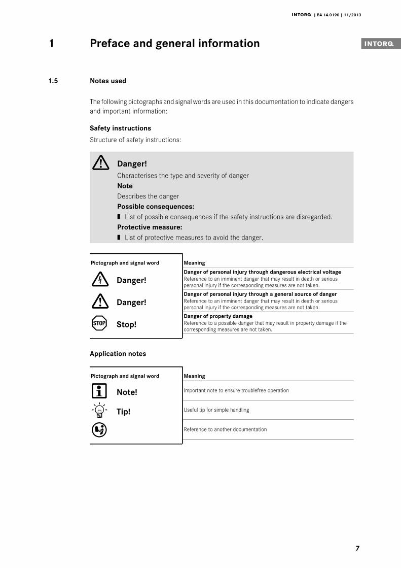
1.5 Notes used
The following pictographs and signal words are used in this documentation to indicate dangersand important information:
Safety instructions
Structure of safety instructions:
Danger!Characterises the type and severity of dangerNoteDescribes the dangerPossible consequences:| List of possible consequences if the safety instructions are disregarded.Protective measure:| List of protective measures to avoid the danger.
Pictograph and signal word Meaning
Danger!Danger of personal injury through dangerous electrical voltageReference to an imminent danger that may result in death or seriouspersonal injury if the corresponding measures are not taken.
Danger!Danger of personal injury through a general source of dangerReference to an imminent danger that may result in death or seriouspersonal injury if the corresponding measures are not taken.
Stop!Danger of property damageReference to a possible danger that may result in property damage if thecorresponding measures are not taken.
Application notes
Pictograph and signal word Meaning
Note! Important note to ensure troublefree operation
Tip! Useful tip for simple handling
Reference to another documentation

Preface and general information1
j | BA 14.0190 | 11/2013
8
1.6 Scope of supply
After receipt of the delivery, check immediately whether it corresponds to the accompanyingpapers. INTORQ does not grant any warranty for deficiencies claimed subsequently.
| Claim visible transport damage immediately to the forwarder.
| Claim visible deficiencies / incompleteness immediately to INTORQ GmbH & Co.KG.
1.7 Disposal
The spring-applied brake consists of different types of material.
| Recycle metals and plastics.
| Ensure professional disposal of assembled PCBs according to applicableenvironmental regulations.
1.8 Drive systems
Labelling
Drive systems and components are unambiguously designated by the indications on thenameplate.
Manufacturer: INTORQ GmbH & Co KG, Wülmser Weg 5, D-31855 Aerzen
| The spring-applied INTORQ brakeis also delivered in single modules and individuallycombined to its modular design. The data - package labels, nameplate, and type codein particular - apply to one complete stator.
| If single modules are delivered, the labelling is missing.

Preface and general information1 i
j | BA 14.0190 | 11/2013
9
1.9 Legal regulations
Liability
| The information, data and notes in this documentation met the state of the art at thetime of printing. Claims referring to products which have already been supplied cannotbe derived from the information, illustrations and descriptions.
| We do not accept any liability for damage and operating interference caused by:
– inappropriate use
– unauthorised modifications to the product
– improper working on and with the product
– operating faults
– disregarding the documentation
Warranty
| Terms of warranty: see terms of sale and delivery of INTORQ GmbH & Co. KG.
| Warranty claims must be made to INTORQ immediately after detecting defects orfaults.
| The warranty is void in all cases where liability claims cannot be made.

Safety instructions2
j | BA 14.0190 | 11/2013
10
2 Safety instructions
2.1 General safety information
| INTORQ components ...
– ... must only be applied as directed.
– ... must not be commissioned if they are noticeably damaged.
– ... must not be technically modified.
– ... must not be commissioned if they are mounted and connected incompletely.
– ... must not be operated without the required covers.
– ... can hold live as well as moving or rotary parts during operation according to theirdegree of protection. Surfaces may be hot.
| For INTORQ components ...
– ... the documentation must always be kept at the installation site.
– ... only permitted accessories are allowed to be used.
– ... only original spare parts of the manufacturer are allowed to be used.
| All specifications of the corresponding enclosed documentation must be observed.
This is vital for a safe and trouble-free operation and for achieving the specified productfeatures.
| Only qualified, skilled personnel are permitted to work on and with INTORQcomponents.
In accordance with IEC 60364 or CENELEC HD 384, qualified, skilled personnel arepersons ...
– ... who are familiar with the installation, mounting, commissioning, and operation ofthe product.
– ... who have the qualifications necessary for their occupation.
– ... who know and apply all regulations for the prevention of accidents, directives, andlaws relevant on site.
| Risk of burns!
– Surfaces may be hot during operation! Provide for protection against accidentalcontact.
| Risk of injury due to a rotating shaft!
– Wait until the motor is at standstill before you start working on the motor.
| The friction lining and the friction surfaces must by no means have contact to oil orgrease since even small amounts reduce the brake torque considerably.
| The brake is designed for operation under the environmental conditions that apply toIP54. Because of the numerous possibilities of using the brake, it is however necessaryto check the functionality of all mechanical components under the correspondingoperating conditions.

Safety instructions2 i
j | BA 14.0190 | 11/2013
11
2.2 Application as directed
| INTORQ components ...
– ... are intended for use in machinery and systems.
– ... must only be used for the purposes ordered and confirmed.
– ... must only be operated under the ambient conditions prescribed in theseOperating Instructions.
– ... must not be operated beyond their corresponding power limits.
Any other use shall be deemed inappropriate!
Possible applications of the INTORQ spring-applied brake
| Humidity: no restrictions
– In case of formation of condensed water and moisture: provide for appropriateventilation to ensure that all components will dry quickly.
| Ambient temperature:
– -20 °C to +40 °C (standard)
| At high humidity and low temperature:
– Take measures to protect armature plate and rotor from freezing.
| Protect electrical connections against contact.
Technical data3
j | BA 14.0190 | 11/2013
12
3 Technical data
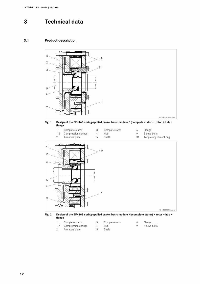
3.1 Product description
BFK46820-003.iso/dms
Fig. 1 Design of the BFK468 spring-applied brake: basic module E (complete stator) + rotor + hub +flange
1 Complete stator 3 Complete rotor 6 Flange1.2 Compression springs 4 Hub 9 Sleeve bolts2 Armature plate 5 Shaft 31 Torque adjustment ring
KL 46820-001.iso/dms
Fig. 2 Design of the BFK468 spring-applied brake: basic module N (complete stator) + rotor + hub +flange
1 Complete stator 3 Complete rotor 6 Flange1.2 Compression springs 4 Hub 9 Sleeve bolts2 Armature plate 5 Shaft

Technical data3 i
j | BA 14.0190 | 11/2013
13
3.1.1 General information
The spring-applied brake is designed for the conversion of mechanical work and kinetic energyinto heat. Due to the static brake torque, the brake can hold loads without speed difference.Emergency braking is possible at high speed. The more friction work, the higher the wear,(operating speeds 16).
The BFK468- spring-applied brake is a single-disk brake with two friction surfaces.Several compression springs (1.2) generate the braking torque by friction locking. The brakeis released electromagnetically by a reduction of the holding current via an INTORQ bridgehalf-wave rectifier.
The stator (1) is designed to be of thermal class F. The limit temperature of the coils is 155°C.
3.1.2 Braking
During braking the rotor (3) axially slidable on the hub (4) is pressed against the frictionsurface by the inner and outer springs (1.2) via the armature plate. The asbestos-freefriction linings ensure a high braking torque and low wear. The braking torque transmissionbetween hub (4) and rotor (3) is effected by means of toothing.
3.1.3 Brake release
In the braked state, there is an air gap ”sL” between the stator (1) and the armature plate (2).To release the brake, the coil of the stator (1) is excited with the DC voltage provided. Themagnetic force generated attracts the armature plate (2) towards the stator (1) against thespring force. The rotor (3) is then released and can rotate freely.
3.1.4 Brake torque reduction
For basic module E (adjustable), the spring force and thus the brake torque can be reducedby unscrewing the adjuster nut (8), ( 37).
3.1.5 Manual release (optional for sizes 18 to 25)
The manual release is optionally available for short-term releases when no voltage is applied.The manual release can be retrofitted.
Technical data3
j | BA 14.0190 | 11/2013
14
3.1.6 Microswitch (optional)
The manufacturer offers the microswitch for air-gap or wear monitoring. The user must providethe corresponding electrical connection ( 31et seqq.).
When air-gap monitoring, the motor does not start before the brake has been released. Withthis set-up, all possible faults are monitored. For example, in the event of defective rectifiers,interrupted connection cables, defective coils, or excessive air gaps the motor will not start.
When checking the wear, no current will be applied to the brake and the motor if the air gapis too large.
3.1.7 Encapsulated design (optional)
This design not only avoids the penetration of spray water and dust, but also the spreadingof abrasion particles outside the brake. This is achieved by:
| a cover seal over the armature plate and rotor,
| a cover in the adjuster nut,
| a shaft seal in the adjuster nut for continuous shafts (option).

Technical data3 i
j | BA 14.0190 | 11/2013
15
3.2 Brake torques
Stop!Please observe that engagement times and disengagement times changedepending on the brake torque.
Size 18 20 25 31
Characteristic torque
Torquereduction Eper detentposition
Characteristic torque
Torquereduction Eper detent
position
Characteristic torque
Torquereduction Eper detent
position
Characteristic torque
[Nm] [Nm] [Nm] [Nm] [Nm] [Nm] [Nm]
230 N
Rated torques [Nm],relating to therelative speed Δn =100 rpmDepending on therated torque (springassembly), the angleof rotation for thebraking torquereduction can be60°, 120° or 180°for basic module E.
100 N/E 6.4 170 N/E 19.8 260 N/E 16.5
115 N/E 6.4 200 N/E 19.8 300 N/E 8.2 720 N
130 N/E 6.4 230 N/E 9.9 350 N/E 8.2 960 N
150 N/E 3.2 260 N/E 9.9 400 N/E 8.2 1200 N
165 N/E 3.2 300 N/E 19.8 445 N/E 16.5 1440 N
185 N/E 6.4 345 N/E 19.8 490 N/E 8.2 1680 N
200 N/E 6.4 400 N/E 19.8 520 N/E 16.5 1920 N
235 N/E 6.4 440 N/E 19.8 600 N/E 16.5 2160 N
265 N/E 6.4 480 N/E 19.8 700 N/E 16.5 2400 N
300 N/E 6.4 520 N/E 19.8 800 N/E 16.5
Tab. 1 N.....Brake torque for module N (without torque adjustment ring)E......Brake torque for module E (with torque adjustment ring)
Holding brake with emergency stop operation (sL max. approx. 2.0 x sLN)Service brake (sL max. approx. 4.0 x sLN)Standard braking torque
3.2.1 Basic module E, brake torque reduction
For basic module E, the braking torque can be reduced by means of the torque adjustmentring in the stator. The torque adjustment ring must only be screwed out up to the maximumprojection ”hEmax.”, 16 and 37.

Technical data3
j | BA 14.0190 | 11/2013
16
3.2.2 Brake torques depending on the speed and permissible limit speeds
Type Rated torque atΔn = 100 rpm
Braking torque at Δn0 [rpm] [%] max. speedΔn0max. with
horizontalmounting position
[%] 1500 3000 maximum [rpm]
BFK468-18
100
77 70
66
4400
BFK468-20 75 68 3700
BFK468-25 73 66 3000
BFK468-31 69 ----- 2300
Tab. 2 Brake torques depending on the speed and permissible limit speeds
3.3 Characteristics
Type sLN+0.1 mm-0.05 mm
sL max.servicebrake
sLmax.holdingbrake
Max.adjustment,permissible
weardistance
Rotor thickness Excessof the torqueadjustmentring hEmax.
[mm] [mm] [mm] [mm] min. 1) [mm] max. [mm] [mm]
BFK468-180 4
1 0 0.6 3.0 10.0 13.0 15
BFK468-201 25
4.0 12.0 16.0 17
BFK468-250 5
0.75 4.5 15.5 20.0 19.5
BFK468-31 1.5 1.0 3.0 15.0 18.0 ----
1) The friction lining is designed such that the brake can be adjusted at least 5 times.
Type Pitch circle Tightening torque Weightof complete stator
[mm] Thread Screws [Nm] Complete lever[Nm]
[kg]
BFK468-18 196 6 x M8 24.6 23 13.4
BFK468-20 2306 x M10 48 40
20.0
BFK468-25 278 31.0
BFK468-31 360 8 x M16 206 ----- 55.1
Tab. 3 Characteristics of BFK468 spring-applied brake

Technical data3 i
j | BA 14.0190 | 11/2013
17
Type Electrical power P 1) Release voltage/holding voltageU
Coil resistance RN ±8 %
[W] [V] [Ω]
BFK468-18 85 / 340205 / 103 123.5
360 / 180 381.5
BFK468-20 100 / 408205 / 103 106.1
360 / 180 317.6
BFK468-25 132 / 528205 / 103 79.6
360 / 180 245.5
BFK468-31 230 / 920 360 / 180 140.9
1) Coil power at 20 _C
Tab. 4 Coil voltage/coil resistance of BFK468
3.3.1 Project planning notes
| The brakes are dimensioned in such a way that the given characteristic torques arereached safely after a short run-in process.
| Due to the fluctuating properties of the organic friction linings used and the alternatingenvironmental conditions, deviations of the given braking torques may occur. Thesemust be considered by corresponding safety measures in the dimensioning process.Especially with humidity and alternating temperatures, an increased breakaway torquemay occur after a long downtime.
| If the brake is used as a pure holding brake without dynamic load, the friction liningmust be reactivated regularly.

Technical data3
j | BA 14.0190 | 11/2013
18
3.4 Operating times
BFKXXX-011.iso/dms
Fig. 3 Operating times of the spring-applied brakes
t1 Engagement time t11 Reaction delay during engagementt2 Disengagement time (up to M = 0.1 Mr) t12 Rise time of the brake torqueMK Characteristic torque U Voltage
Type Rated torque atΔn = 100 rpm
Max. permissiblefriction work per
operation only
Transitionoperatingfrequency
Operating times [ms] at sLN
MK1) QE shue DC engagement Disengage
[Nm] [J] [h-1] t11 t12 t1 t2
BFK468-18 150 60000 20 26 30 56 70
BFK468-20 260 80000 19 102 112 168 106
BFK468-25 400 120000 15 60 135 197 120
BFK468-31 1200 300000 13 65 133 198 250
1) Minimum braking torque when all components are run in
Tab. 5 Switching energy - operating frequency - operating times
Engagement time
The transition from brake-torque free state to holding braking torque is not free of time lags.
A braking torque reduction via the torque adjustment ring prolongs the engagement time andreduces the disengagement time.
| The engagement times are valid for DC switchingwith a spark suppressor.
– Spark suppressors are available for the rated voltages.
– Connect the spark suppressors in parallel to the contact. If this is not admissible forsafety reasons, e.g. with hoists and lifts, the spark suppressor can also beconnected in parallel to the brake coil.
– Circuit proposals: 31, Fig. 15
| The engagement times are approx. 5 times longer with AC switching.
– Connection: 31, Fig. 14
Technical data3 i
j | BA 14.0190 | 11/2013
19
Disengagement time
The disengagement time is the same for DC and AC switching.
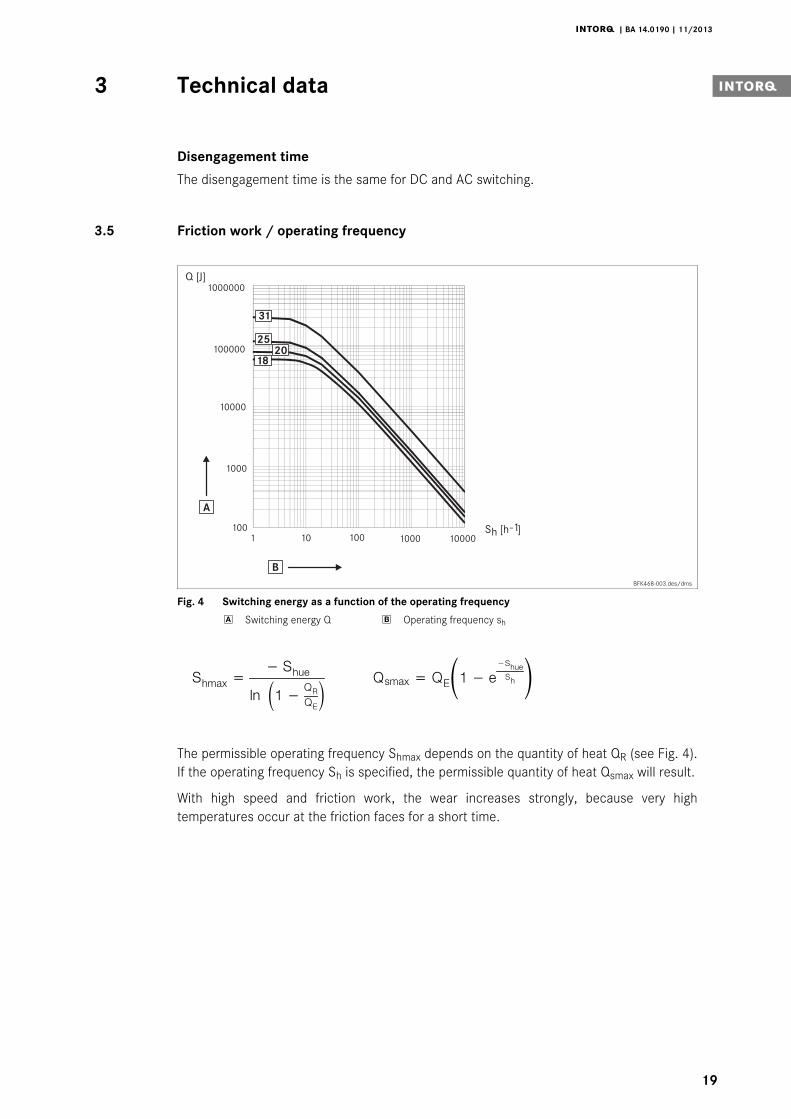
3.5 Friction work / operating frequency
1 10 100 1000 10000100
1000
10000
100000
1000000Q [J]
S [h ]h -1
31
25
20
18
A
B
BFK468-003.des/dms
Fig. 4 Switching energy as a function of the operating frequency
Switching energy Q Operating frequency sh
pÜã~ñ=− pÜìÉ
äå N− nonb nëã~ñ= nbN− É
−pÜìÉpÜ
The permissible operating frequency Shmax depends on the quantity of heat QR (see Fig. 4).If the operating frequency Sh is specified, the permissible quantity of heat Qsmax will result.
With high speed and friction work, the wear increases strongly, because very hightemperatures occur at the friction faces for a short time.
Technical data3
j | BA 14.0190 | 11/2013
20
3.6 Emission
Electromagnetic compatibility
Note!The user must ensure compliance with EMC Directive 2004/108/EC usingappropriate controls and switching devices.
If an INTORQ rectifier is used for the DC switching of the spring-applied brake and if theoperating frequency exceeds five switching operations per minute, the use of a mains filteris required.
If the spring-applied brake uses a rectifier of another manufacturer for the switching, itmay become necessary to connect a spark suppressor in parallel with the AC voltage.Spark suppressors are available on request, depending on the coil voltage.
Heat
Since the brake converts kinetic energy as well as mechanical and electrical energy into heat,the surface temperature varies considerably, depending on the operating conditions andpossible heat dissipation. Under unfavourable conditions, the surface temperature can reach130 _C.
Noise
The switching noise during engagement and disengagement varies depending on the air gap”sL” and the brake size.
Depending on the natural oscillation after installation, operating conditions and state of thefriction faces, the brake may squeak during braking.
Others
The abrasion of the friction parts produces dust.

Mechanical installation4 i
j | BA 14.0190 | 11/2013
21
4 Mechanical installation
Stop!Toothed hub and screws must not be lubricated with grease or oil!
4.1 Necessary tools
Type Torque keyInsert for hexagon socket
screws
Wrench size of open-jawed spanner [mm] Hook wrenchDIN 1810design A
Box spannerfor flange
installation,outside
*Manualrelease
Measuringrange [Nm]
Wrench size[mm]
Sleeve bolts Nuts / bolts 2kt lever Diameter[mm]
Wrench size[mm]
BFK468-18
20 - 100
6 x 1/2”square 15
- / 10
10 110 - 115 13 x 1/2”square
BFK468-20 8 x 1/2”square 17
12 135 - 145 17 x 1/2”squareBFK468-25 14 155 - 165
BFK468-31 40 - 200 14 x 1/2”square 24 - / - ----- ----- 24 x 1/2”
square
* for flange mounting insertion with journal guide
Feeler gauge Caliper gauge Multimeter

Mechanical installation4
j | BA 14.0190 | 11/2013
22
4.2 Mounting
4.2.1 Preparation
1. Unpack spring-applied brake.
2. Check for completeness.
3. Check nameplate data, especially rated voltage.
4.3 Installation
When you have ordered a version with manual release or flange, attach these units first.
4.3.1 Installation of the hub onto the shaft
Stop!In reverse operation, it is recommended to additionally glue the hub to the shaft!
KL BFK46825-001-a.iso
Fig. 5 Mounting the hub onto the shaft
4 Hub 4.2 Circlip 15 End shield4.1 Keyway
1. Press hub (4) onto the shaft.
2. Secure hub against axial displacement, e.g. using a circlip (4.2).

Mechanical installation4 i
j | BA 14.0190 | 11/2013
23
4.3.2 Installation of the brake
Stop!| Minimum requirement of the end shield (15):– Material S235 JR or C15 (other materials after consultation with INTORQ),– Levelness 0.10 mm,– Axial runout 0.10 mm,– Roughness Rz 10 to Rz 16
| When dimensioning the thread depth in the end shield (15), the permissiblewear distance must be taken into consideration, 16.
| Condition of the end shield (15):– It has to be free of grease and oil.
Mounting the flange without additional screws
KL BKF46825-001-d.iso
Fig. 6 Flange assembly BFK468
6 Flange 15 End shield
1. Hold the flange (6) against the end shield (15) and check the pitch circle and retainingscrew drill hole threading.
2. Assemble the brake with the corresponding screw set (see chapter 4.3.2).

Mechanical installation4
j | BA 14.0190 | 11/2013
24
BFK46825-008.iso/dms
Fig. 7 Mounting the brake
3 Complete rotor 6 Flange 15 End shield4 Hub
1. Push the rotor (3) onto the hub (4) and check whether it can be moved by hand(Fig. 7).
Stop!Please note the following for the version ”brake with shaft sealing ring in torqueadjustment ring”:
2. Lightly lubricate the lip of the shaft seal with grease.
3. When assembling the stator (1), push the shaft sealing ring carefully over the shaft.
– The shaft should be located concentrically to the shaft seal.

Mechanical installation4 i
j | BA 14.0190 | 11/2013
25
BFK46825-003.iso
Fig. 8 Mounting of the complete stator
1 Complete stator 7 Connector block10 Cheese head screw 15 End shield
4. Screw the complete stator (1) onto the end shield (15) using the set of screws (10)provided and a torque key, (tightening torque 16).
BFK46825-005.iso/dms
Fig. 9 Inspection of the air gap sL
sAR 9 Sleeve bolts 15 End shield1 Stator 10 Cheese head screws
1. Check the air gap near the screws (10) by means of a feeler gauge and compare thevalues to the values for ”sLN” in the table ( 16).
Note!Do not insert feeler gauge more than 10 mm between armature plate (2) andstator (1.1)!
Mechanical installation4
j | BA 14.0190 | 11/2013
26
BFK46825-006.iso
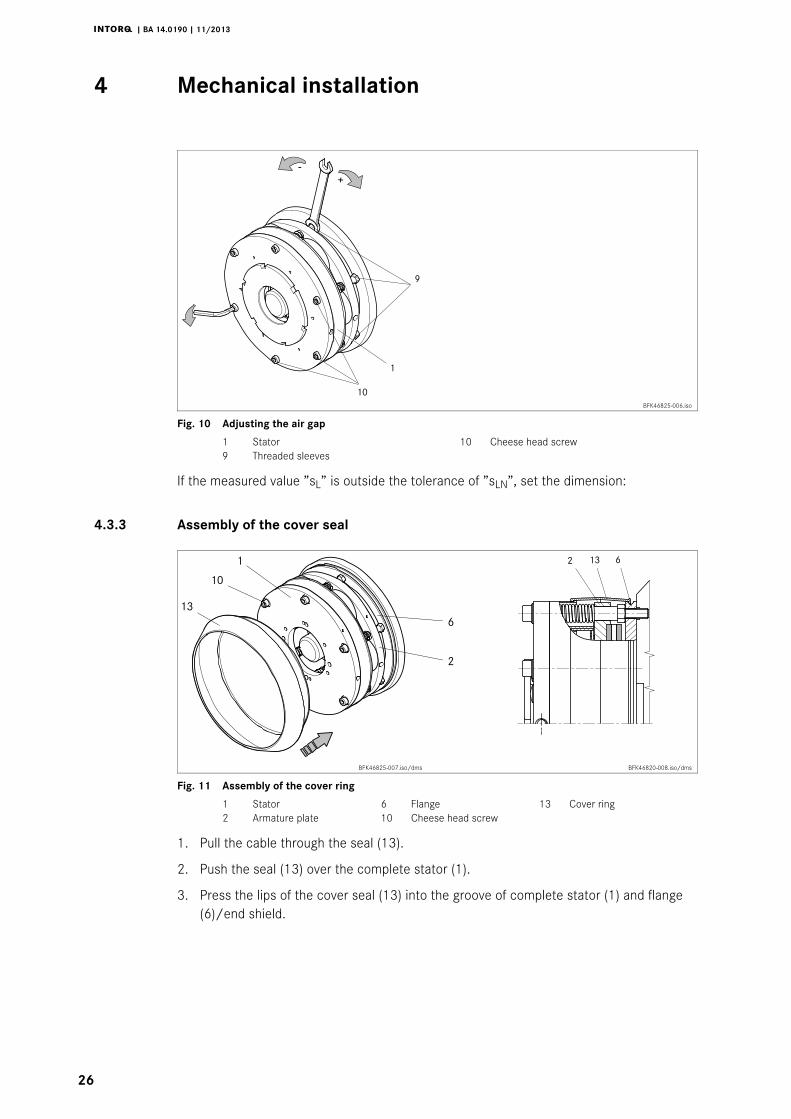
Fig. 10 Adjusting the air gap
1 Stator 10 Cheese head screw9 Threaded sleeves
If the measured value ”sL” is outside the tolerance of ”sLN”, set the dimension:
4.3.3 Assembly of the cover seal
BFK46825-007.iso/dms BFK46820-008.iso/dms
Fig. 11 Assembly of the cover ring
1 Stator 6 Flange 13 Cover ring2 Armature plate 10 Cheese head screw
1. Pull the cable through the seal (13).
2. Push the seal (13) over the complete stator (1).
3. Press the lips of the cover seal (13) into the groove of complete stator (1) and flange(6)/end shield.
Mechanical installation4 i
j | BA 14.0190 | 11/2013
27
4.3.4 Assembly of the manual release sizes 18 to 25
BFK46825-009.iso
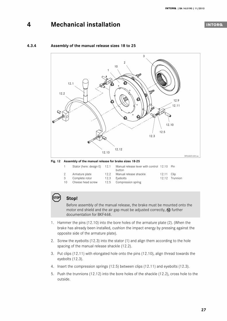
Fig. 12 Assembly of the manual release for brake sizes 18-25
1 Stator (here: design E) 12.1 Manual release lever with controlbutton
12.10 Pin
2 Armature plate 12.2 Manual release shackle 12.11 Clip3 Complete rotor 12.3 Eyebolts 12.12 Trunnion10 Cheese head screw 12.5 Compression spring
Stop!Before assembly of the manual release, the brake must be mounted onto themotor end shield and the air gap must be adjusted correctly, furtherdocumentation for BKF468.
1. Hammer the pins (12.10) into the bore holes of the armature plate (2). (When thebrake has already been installed, cushion the impact energy by pressing against theopposite side of the armature plate).
2. Screw the eyebolts (12.3) into the stator (1) and align them according to the holespacing of the manual release shackle (12.2).
3. Put clips (12.11) with elongated hole onto the pins (12.10), align thread towards theeyebolts (12.3).
4. Insert the compression springs (12.5) between clips (12.11) and eyebolts (12.3).
5. Push the trunnions (12.12) into the bore holes of the shackle (12.2), cross hole to theoutside.

Mechanical installation4
j | BA 14.0190 | 11/2013
28
6. Push the cheese head screws (12.13) through the cross holes of the trunnions(12.12).
7. Locate the shackle (12.2) with trunnions (12.12) and cheese head screws (12.13)such onto the back of the stator (1) that the cheese head screws (12.13) are ledthrough the eyebolts (12.3) and the compression springs (12.5).
8. Screw the cheese head screws (12.13) into the clip threads (12.11).
9. Adjust gap ”s” using the cheese head screws (12.13), (values for ”s ” 28.
10. Secure the adjustment of the cheese head screws (12.13) using the threaded pin(12.9) in the clip (12.11).
Note!Dimension ”s + sL” can be checked through the difference of the fitting lengthof the compression springs when the armature plate is attracted towards thestator and the manual release has been adjusted.
11. If necessary, screw the lever (12.1) into the shackle (12.2).
BFK46820-006.iso
Type sL (mm) s +0.1 (mm) s + sL (mm)
BFK468-18 0.4 2.0 2.4
BFK468-20 0.4 2.0 2.4
BFK468-25 0.5 2.5 3.0
Tab. 6 Adjustment setting for manual release
Stop!Dimension ”s” must be observed! Check air gap ”sL”.

Electrical installation5 i
j | BA 14.0190 | 11/2013
29
5 Electrical installation
5.1 Bridge/half-wave rectifiers (option)
BEG-561--Bridge/half-wave rectifiers are used for the supply of electromagnetic spring-applied DCbrakes which have been released for operation with such rectifiers. Any other use is onlypermitted with the explicit written approval of INTORQ.
Once a set overexcitation time has elapsed, the bridge/half-wave rectifiers switch over frombridge rectification to half-wave rectification.
Terminals 3 and 4 are located in the DC circuit of the brake. The induction voltage peak forDC switching (see ”DC switching - fast engagement” circuit diagram) is limited by anintegrated overvoltage protection at terminals 5 and 6.
Fig. 13 BEG-561 attachment features
5.1.1 Technical data
Rectifier type Bridge/half-wave rectifier
Output voltage for bridge rectification 0.9 x U1
Output voltage for half-wave rectification 0.45 x U1
Ambient temperature (storage/operation) [°C] -25 ... +70
Type Input voltage U1(40 Hz ... 60 Hz)
Max. current Imax. Overexcitation time tue ( ±20%)
min.[V ∼ ]
rated[V ∼ ]
max.[V ∼ ]
bridge[A]
half-wave[A]
with U1 min[s]
with U1rated [s]
with U1max [s]
BEG-561-255-030160 230 255 3.0 1.5
0.430 0.300 0.270
BEG-561-255-130 1.870 1.300 1.170
BEG-561-440-030-1230 400 440
1.5 0.75 0.500 0.300 0.270
BEG-561-440-130 3.0 1.5 2.300 1.300 1.200
Input voltage U1 (40 ... 60 Hz)Tab. 7 Data for bridge/half-wave rectifier type BEG-561

Electrical installation5
j | BA 14.0190 | 11/2013
30
5.1.2 Reduced switch-off times
When switching on the DC side (fast engagement), switching on the AC side is also required!Otherwise, there will be no overexcitation during power-on.
Delayed engagement Fast engagement
1 2 3 4 65
1 2 3 4 65
Mains Bridge Coil
5.1.3 Permissible current load - ambient temperature
BFKXXX-008.iso
1 For screw assembly with metal surface (good heat dissipation)2 For other assembly (e.g. glue)
5.1.4 Assignment: Bridge/half-wave rectifier - brake size
Rectifier type AC voltage Coil voltagerelease/holding
Assigned brake
[V AC] [V DC]
BEG-561-255-030230 ±10% 205 / 103
BFK468-18BFK468-20
BEG-561-255-130 BFK468-25
BEG-561-440-030-1400 ±10% 360 / 180
BFK468-18BFK468-20
BEG-561-440-130 BFK468-25BFK468-31

Electrical installation5 i
j | BA 14.0190 | 11/2013
31
5.2 Electrical connection
Danger!The brake must only be electrically connected when no voltage is applied!
5.2.1 Circuit proposals
BFKXXX-007.iso
Fig. 14 AC switching, delayed engagement
Bridge rectifier/half-wave rectifier
BFKXXX-002.iso
Fig. 15 DC switching, normal engagement
Bridge rectifier/half-wave rectifier
Stop!For switching on the DC side the brake must be operated with a sparksuppressor to avoid impermissible overvoltages.

Electrical installation5
j | BA 14.0190 | 11/2013
32
KL-BFKXXX-003.iso
Fig. 16 With microswitch (release check); connection diagram also valid for star connection
DC voltage depending on coil voltage Spark suppressor
KL-BFKXXX-004.iso
Fig. 17 With microswitch / wear check addition for all circuits; connection diagram also valid for starconnection
Electrical installation5 i
j | BA 14.0190 | 11/2013
33
Tip!During operation according to Fig. 17 the air gap is only monitored when no voltage is appliedto the brake. This makes sense because it is possible that when the current flows only oneside of the armature plate is attracted at first. This misalignment may cause a simulation of themaximum air gap and the actuation of the microswitch. If there is no closed contact in parallelto the microswitch contact, motor and brake will be switched off. The microswitch contact isclosed again when the armature plate is completely released - the release is repeated again -because of the small difference-contact travel of the microswitch.To avoid this misinterpretation of the microswitch signal, the signal should only be processedwhen no voltage is applied to the brake.
1. Mount the rectifier in the terminal box. With motors of the insulation class ”H”, mountthe rectifier in the control cabinet. Permissible ambient temperature for the rectifier-25 _C to +70 _C.
2. Compare the coil voltage of the stator to the DC voltage of the rectifier installed.Conversion of supply voltage to DC voltage:
– Bridge rectifier: UDC = UAC • 0.9
– Half-wave rectifier: UDC = UAC • 0.45
– Permissible deviation of Ucoil and UDC up to ±10%.
3. Select suitable circuit diagram ( 31).
Note!Selection of the rectifier at voltages ≥ 460 V AC catalogue ”Electronicswitchgear and accessories” Chapter spark suppressors and rectifiers.
4. Motor and brake must be wired according to the requirements of the engagementtime.
Commissioning and operation6
j | BA 14.0190 | 11/2013
34
6 Commissioning and operation
Danger!The live connections and the rotating rotor must not be touched.The drive must not be running when checking the brake.
6.1 Functional test
In the event of failures, refer to the troubleshooting table, 45. If the fault cannot beeliminated, please contact the aftersales service.
6.1.1 Release / voltage check
For brakes without microswitch only
Danger!The brake must be free of residual torque. The motor must not rotate.
Danger!Live connections must not be touched.
1. Remove two bridges from the motor terminals. Do not switch off the DC brake supply.When connecting the rectifier to the neutral point of the motor, the PE conductor mustalso be connected to this point.
2. Connect the mains supply.
3. Measure the DC voltage at the brake.
– Compare the DC voltage measured with the voltage specified on the nameplate. A10 % deviation is permissible.
4. Check air gap ”sL”. It must be zero and the rotor must rotate freely.
5. Switch off the current.
6. Bolt bridges to the motor terminals. Remove additional PEN conductor.
6.1.2 Microswitch - release check
Danger!The brake must be free of residual torque. The motor must not rotate.
Commissioning and operation6 i
j | BA 14.0190 | 11/2013
35
Danger!Live connections must not be touched.
1. The switching contact for the brake must be open.
2. Remove two bridges from the motor terminals to deenergise the motor.
– Do not switch off the DC brake supply.
– When connecting the rectifier to the neutral point of the motor, the PE conductormust also be connected to this point.
3. Apply DC voltage to the brake.
4. Measure the AC voltage at the motor terminals. It must be zero.
5. Close the switching contact for the brake.
– The brake is released.
6. Measure the DC voltage at the brake:
– Compare the DC voltage measured with the voltage specified on the nameplate. A±10 % deviation is permissible.
7. Check air gap ”sL”.
– It must be zero and the rotor must rotate freely.
6.1.3 Microswitch - wear check
Danger!The brake must be free of residual torque. The motor must not rotate.

Commissioning and operation6
j | BA 14.0190 | 11/2013
36
Danger!Live connections must not be touched.
1. Remove two bridges from the motor terminals. Do not switch off the DC voltage forthe brake. When connecting the rectifier to the neutral point of the motor, the PEconductor must also be connected to this point.
2. Set air gap to ”sLmax.”. Description 23 worksteps 8-11.
3. Connect the mains supply.
4. Measure the AC voltage at the motor terminals and the DC voltage at the brake. Bothmust be zero.
5. Switch off the current.
6. Set air gap to ”sLN”. Description 23 worksteps 8-11.
7. Connect the mains supply.
8. Measure the AC voltage at the motor terminals. It must be the same as the mainsvoltage.
9. Measure the DC voltage at the brake.
– The DC voltage measured after the overexcitation time (see bridge/half-waverectifier) must be half the voltage indicated on the nameplate. A 10 % deviation ispermissible.
10. Check air gap ”sL”. It must be zero and the rotor must rotate freely.
11. Switch off the current for the brake.
12. Bolt bridges to the motor terminals. Remove additional PEN conductor.
6.1.4 Manual release
Stop!This operational test is to be carried out additionally!

Commissioning and operation6 i
j | BA 14.0190 | 11/2013
37
Danger!The brake must be free of residual torque. The motor must not rotate.
1. Pull the lever (Fig. 18) with approx. 250 N until the resistance increases strongly.
Stop!Additional tools to facilitate brake release are not allowed! (e.g. extension piece)
2. The rotor must rotate freely. Small residual torques are permissible.
3. Release the lever.
6.2 Reducing the brake torque
M-
M+
BFK46825-010-a.iso BFK46820-012.iso
Fig. 18 Braking torque adjustment
1 Stator31 Torque adjustment ring
Commissioning and operation6
j | BA 14.0190 | 11/2013
38
1. Turn the adjuster nut (8) counterclockwise using the hook wrench.
– Observe the notches. Positions between notches are impermissible. (Values for thebrake torque reduction see chapter 3.2.1).
– The maximum permissible projection ”hEmax.” of the adjuster nut (8) to the stator (7)is to be observed (values for ”hEmax.” see chapter 3.3).
Danger!The reduction of the brake torque does not increase the maximum permissibleair gap ”sLmax.”.Do not change the manual release setting for models with manual release.
6.3 During operation
| Check the brake regularly during operation. Take special care of:
– unusual noises or temperatures
– loose fixing elements
– the condition of the electrical cables.
| The armature plate must be attracted and the drive must move without residualtorque.
| Measure the DC voltage at the brake.
– Compare the DC voltage measured with the voltage specified on the nameplate. A±10 % deviation is permissible.

Maintenance/repair7 i
j | BA 14.0190 | 11/2013
39
7 Maintenance/repair
7.1 Wear of spring-applied brakes
The following table describes the different causes of wear and their effects on the componentsof the spring-applied brake. The important influencing factors must be quantified so that theservice life of the rotor and brake can be calculated and that the maintenance intervals to beprescribed can be specified precisely. The most important factors in this context are theapplied friction energy, the initial speed of braking and the operating frequency. If several ofthe causes of friction lining wear occur in an application at the same time, the influencingfactors are to be added together when the amount of wear is calculated.
Component Cause Effect Influencing factors
Friction lining Braking during operation
Wear of friction lining
Friction work
Emergency stops
Overlapping wear during start andstop of drive
Active braking via the drive motorwith support of brake (quick stop)
Starting wear in case of motormounting position with verticalshaft, even when the brake is notapplied
Number of start/stop cycles
Armature plate andcounter friction face
Rubbing of brake lining Run-in of armature plate andcounter friction face
Friction work
Brake support Load alternation and jerks in thebacklash between armature plate,sleeve bolts and guide bolt
Breaking of armature plate, sleevebolts and guide bolt
Number of start/stop cycles,braking torque
Springs Axial load cycle and shear stress ofsprings through radial backlash onreversal of armature plate
Reduced spring force or fatiguefailure
Number of switching operations ofbrake
Tab. 8 Causes for wear

Maintenance/repair7
j | BA 14.0190 | 11/2013
40
7.2 Inspections
7.2.1 Important notes
To ensure safe and trouble-free operation, spring-applied brakes must be checked andmaintained at regular intervals. Servicing can be made easier if good accessibility of thebrakes is provided in the plant. This must be considered when installing the drives in the plant.
Primarily, the necessary maintenance intervals for industrial brakes result from the load duringoperation. When calculating the maintenance interval, all causes for wear must be taken intoaccount, ( 39). For brakes with low loads such as holding brakes with emergency stop, werecommend a regular inspection at a fixed time interval. To reduce the cost, the inspectioncan be carried out along with other regular maintenance work in the plant if necessary.
If the brakes are not maintained, failures, production losses or damage to the system mayoccur. Therefore, a maintenance concept adapted to the particular operating conditions andbrake loads must be defined for every application. For the spring-applied brakes, themaintenance intervals and maintenance operations listed in the below table must be provided.The maintenance operations must be carried out as described in the detailed descriptions.
Danger!The live connections and the rotating rotor must not be touched.The drive must not be running when checking the brake.
7.2.2 Checking the rotor thickness
1. Remove the motor cover and seal ring, if mounted.
2. Measure the rotor thickness using a caliper gauge.
3. Compare the measured rotor thickness with the minimally permissible rotor thickness,( 16).
4. If required, replace rotor completely, ( 42).
7.2.3 Checking the air gap
Danger!Disconnect the drive from the load to prevent accidents. During the nextinspection steps of the spring-applied brake, the motor must not run!
1. Check the air gap ”sL” near the fixing screws between the armature plate and statorusing a feeler gauge ( 16).
2. Compare air gap measured to maximally permissible air gap ”sL max.” ( 16).
3. If required, set air gap to ”sLN” ( 41).

Maintenance/repair7 i
j | BA 14.0190 | 11/2013
41
7.2.4 Release / voltage
Danger!The running rotor must not be touched.
Danger!Live connections must not be touched.
7.3 Maintenance operations
7.3.1 Adjusting the air gap
Danger!The brake must be free of residual torque.
Stop!Please observe when mounting the flange with additional screws:Behind the threaded holes for the screws in the flange there must be clearingholes in the endshield. Without clearing holes the minimum rotor thicknesscannot be used. Under no circumstances may the screws be pressed againstthe endshield.
1. Unbolt screws (Fig. 10).
2. Screw the threaded sleeves into the stator by using a spanner. 1/6 revolution reducesthe air gap by approx. 0.15 mm.
3. Tighten screws, torques 16.
4. Check air gap ”sL” near the screws using a feeler gauge, ”sLN” 16.
5. If the difference between the measured air gap and ”sLN” is too large, repeat thereadjustment.
Maintenance/repair7
j | BA 14.0190 | 11/2013
42
7.3.2 Rotor replacement
Danger!The brake must be free of residual torque.
1. Switch off voltage!
2. Disconnect the supply cable.
3. Loosen the screws evenly and remove them completely.
4. Remove the complete stator from the end shield. Observe the supply cable.
5. Pull the complete rotor off the hub.
6. Check hub teeth.
7. Replace the hub as well if worn.
8. Check the friction surface at the end shield. In case of strong scoring at the flange,replace the flange. If scoring occurs at the end shield, re-finish end shield.
9. Measure rotor thickness (new rotor) and sleeve bolt head with a caliper gauge.
10. Calculate the gap between the stator and the armature plate as follows:
Gap = rotor thickness + sLN - head height
”sLN” 16
11. Unscrew the sleeve bolts evenly until the calculated gap between stator and armatureplate is reached.
12. Install and adjust new rotor and stator, 23.
13. Reconnect the supply cable.
Maintenance/repair7 i
j | BA 14.0190 | 11/2013
43
7.4 Spare-parts list
| Only parts with item numbers are available.
– The item numbers are only valid for the standard design.
| Please include the following information with the order:
– Order number of the brake
– Position number of the spare part
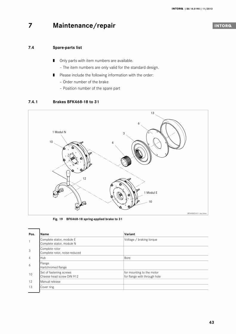
7.4.1 Brakes BFK468-18 to 31
BFK45825-011.iso/dms
Fig. 19 BFK468-18 spring-applied brake to 31
Pos. Name Variant
1 Complete stator, module EComplete stator, module N
Voltage / braking torque
3 Complete rotorComplete rotor, noise-reduced
4 Hub Bore
6 FlangeHartchromed flange
10 Set of fastening screwsCheese head screw DIN 912
for mounting to the motorfor flange with through hole
12 Manual release
13 Cover ring
Maintenance/repair7
j | BA 14.0190 | 11/2013
44
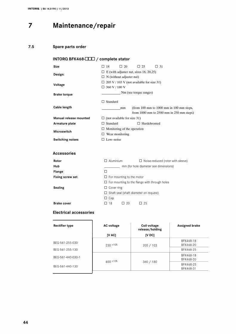
7.5 Spare parts order
INTORQ BFK468- / complete stator
Size 18 20 25 31
Design: E (with adjuster nut, sizes 18, 20,25) N (without adjuster nut)
Voltage 205 V / 103 V (not available for size 31) 360 V / 180 V
Brake torque ___________ Nm (see torque ranges)
Cable length
Standard
___________mm (from 100 mm to 1000 mm in 100 mm steps,from 1000 mm to 2500 mm in 250 mm steps)
Manual release mounted (not available for size 31)
Armature plate Standard Hardchromed
MicroswitchMonitoring of the operation
Wear monitoring
Switching noises Low--noise
Accessories
Rotor Aluminium Noise-reduced (rotor with sleeve)
Hub _________ mm (for hole diameter see dimensions)
Flange Fixing screw set For mounting to the motor
For mounting to the flange with through holes
Sealing Cover ring
Shaft seal (shaft diameter on request)
Cap
Brake cover 18 20 25
Electrical accessories
Rectifier type AC voltage Coil voltagerelease/holding
Assigned brake
[V AC] [V DC]
BEG-561-255-030230 ±10% 205 / 103
BFK468-18BFK468-20
BEG-561-255-130 BFK468-25
BEG-561-440-030-1400 ±10% 360 / 180
BFK468-18BFK468-20
BEG-561-440-130 BFK468-25BFK468-31

Troubleshooting and fault elimination8 i
j | BA 14.0190 | 11/2013
45
8 Troubleshooting and fault elimination
If any malfunctions should occur during operation, please check the possible causes using thefollowing table. If the fault cannot be eliminated by one of the listed measures, please contactthe aftersales service.
Fault Cause RemedyBrake does not release Coil interruption | Measure coil resistance using multimeter:
– If resistance is too high, replace the completestator.
Coil has interturn fault or short circuit toground
| Measure coil resistance using multimeter:– Compare measured resistance to rated
resistance. For values, see 16. If theresistance is too low, replace the completestator.
| Check coil for short circuit to ground using amultimeter:– Replace the complete stator if short circuit to
ground is detected.| Check brake voltage (see ”defective rectifier,
voltage too low”).Wiring incorrect or defective | Check and correct wiring.
| Check cable continuity using a multimeter:– Replace defective cable.
Rectifier defective or wrong | Measure rectifier DC voltage using a multimeter.If DC voltage is zero:| Check AC rectifier voltage.If AC voltage is zero:
– Apply voltage,– check fuse,– check wiring
If AC voltage is ok:– Check rectifier– replace defective rectifier
| Check coil for fault between turns and shortcircuit to ground.
| If the rectifier defect occurs again, replace thecomplete stator, even if no fault between turns orshort circuit to ground can be detected. The faultmay only occur when warm.
Incorrect microswitch wiring Check microswitch wiring and correct it.
Incorrect microswitch setting Replace the complete stator and complain about theincorrect microswitch setting to the manufacturer.
Air gap too big Adjust air gap ( 41)Measure rotor thickness and compare with minimumrotor thickness ( 16). If necessary, replace rotor.
Rotor cannot rotate freely Wrong setting of manual release Check dimension ”s+sL” with energised brake. Thedimension must be identical on both sides. Correct ifnecessary.
Air gap ”sL” too small Check air gap ”sL” and, if required, readjust it (41).

Troubleshooting and fault elimination8
j | BA 14.0190 | 11/2013
46
RemedyCauseFaultRotor not thick enough Rotor has not been replaced in time Replace rotor ( 42)
Voltage is not zero during functionaltest (chapter 6.1)
Incorrect wiring of microswitch Check and correct the microswitch wiring.
Defective microswitch or incorrectsetting
Replace the entire stator and send the defectivestator to the manufacturer.
Voltage too high Brake voltage does not match therectifier
Adapt rectifier and brake voltage to each other.
Voltage too low Brake voltage does not match therectifier
Adapt rectifier and brake voltage to each other.
AC voltage is not mains voltage Fuse missing or defective Select a connection with proper fusing.
Incorrect wiring of microswitch Check the microswitch wiring and correct it.
Defective microswitch or incorrectsetting
Replace the entire stator and send the defectivestator to the manufacturer.

Notes i
j | BA 14.0190 | 11/2013
47

INTORQ GmbH & Co KGGermanyPostfach 1103D-31849 AerzenWülmser Weg 5D-31855 Aerzen+49 5154 70534-444+49 5154 [email protected]
INTORQ (SHANGHAI) Co., LtdChinaNo. 600, Xin Yuan RoadBuilding No. 6 / Zone BNan Hui District, LingangShanghai, China 201306应拓柯制动器(上海)有限公司中国新元南路600号6号楼1楼B座上海 南汇 201306
+86 21 20363-810+86 21 [email protected]
INTORQ US Inc.USA300 Lake Ridge Drive SESmyrna, GA 30082+1 678 309-1155+1 678 [email protected]
3300
2357
|BA
14.0
190
|EN
|3.
0|
©11
.201
3|
TD09
|10
98
76
54
32
1
www.intorq.com