aac aa - instytut...
TRANSCRIPT

ISSN 0509-6669
TRANSACTIONS
OF THE INSTITUTE OF AVIATION
Scientific Quarterly
2 / 2005 (181)
State of the art in Landing gear
Shock abSorberS
Zbigniew WOlEjSZA
Wojciech kOWAlSkI
institute of aviation, Warsaw
Arnaud lAFITTE
Messier dowty Sa, Vélizy
Grzegorz MIkUlOWSkI
institute of fundamental technological research, Warsaw
lars REMMERS
eadS deutschland gmbh, Munich
Edition is sponsored by State Comittee for Scientific Research

Institute of Aviation Editorial Board
Zdobysław Goraj, Jerzy Jachimowicz, Marian Jeż, Wojciech Kania, Tadeusz Korsak (Board Secretary),
Wojciech Potkański, Kazimierz Szumański (Board Chairman), Zbigniew Wołejsza
Summary
This report describes the state of the art in landing gear design with a particular focus on shock
absorbers. It gives an overview on the general design solutions and installation of landing gears into
the airframe. An emphasis is placed on the function and calculation of loads acting on oleopneumatic
shock absorbers, which are the main type of shock absorber considered within ADLAND. One part of
this document covers the requirements which are the basis of the shock absorber design, materials
used and related future developments within aerospace industry. A brief summary is given on research
performed on active shock absorbers so far.
Project�EU��ADLAND�No.�IST-FP&-2002-Aero�1-502793-STREP
Publisher: Institute of Aviation
Scientific Publications Group
Al. Krakowska 110/114, 02-256 Warszawa, phone (48 22) 846 00 11 ext. 442
Edition, revision and computer typesetting: Iwonna Olesińska, Tadeusz Korsak
Printers: ALKOR, 05-070 Sulejówek, Krucza 4
ISSN�0509-6669

State of the art in Landing gear .... 3
CONTENTS
1. INTRODUCTION . . . . . . . . . . . . . . . . . . . . . . . . . . . . . . . . . . . . . . . . . . . . . . . . . . . . . . . . . . . . . . . 5
1.1. Functional Groups of Aircraft . . . . . . . . . . . . . . . . . . . . . . . . . . . . . . . . . . . . . . . . . . . . . . . . 5
1.1.1. Commercial aircraft . . . . . . . . . . . . . . . . . . . . . . . . . . . . . . . . . . . . . . . . . . . . . . . . . . . . . . . 5
1.1.2. Light aircraft . . . . . . . . . . . . . . . . . . . . . . . . . . . . . . . . . . . . . . . . . . . . . . . . . . . . . . . . . . . . . 6
1.1.3. Military aircraft . . . . . . . . . . . . . . . . . . . . . . . . . . . . . . . . . . . . . . . . . . . . . . . . . . . . . . . . . . . 6
1.2. Landing Gears . . . . . . . . . . . . . . . . . . . . . . . . . . . . . . . . . . . . . . . . . . . . . . . . . . . . . . . . . . . . 7
1.2.1. Commercial aircraft . . . . . . . . . . . . . . . . . . . . . . . . . . . . . . . . . . . . . . . . . . . . . . . . . . . . . . . 7
1.2.2. Light Aircraft . . . . . . . . . . . . . . . . . . . . . . . . . . . . . . . . . . . . . . . . . . . . . . . . . . . . . . . . . . . . . 8
1.2.3. Military Aircraft . . . . . . . . . . . . . . . . . . . . . . . . . . . . . . . . . . . . . . . . . . . . . . . . . . . . . . . . . . 8
1.3. General Arrangement of Landing Gears . . . . . . . . . . . . . . . . . . . . . . . . . . . . . . . . . . . . . . . 8
1.3.1. Landing gear arrangement in commercial aircraft . . . . . . . . . . . . . . . . . . . . . . . . . . . . . . . . 8
1.3.2. Landing gear arrangement in light aircraft . . . . . . . . . . . . . . . . . . . . . . . . . . . . . . . . . . . . . . . 10
1.3.3. Landing gear arrangement in military aircraft . . . . . . . . . . . . . . . . . . . . . . . . . . . . . . . . . . . . 10
1.4. Landing geartypes . . . . . . . . . . . . . . . . . . . . . . . . . . . . . . . . . . . . . . . . . . . . . . . . . . . . . . . . . . 11
2. SHOCK ABSORBERS . . . . . . . . . . . . . . . . . . . . . . . . . . . . . . . . . . . . . . . . . . . . . . . . . . . . . . . . . . . 14
2.1. Air-Spring Function . . . . . . . . . . . . . . . . . . . . . . . . . . . . . . . . . . . . . . . . . . . . . . . . . . . . . . . 21
2.2. Air Spring Tuning . . . . . . . . . . . . . . . . . . . . . . . . . . . . . . . . . . . . . . . . . . . . . . . . . . . . . . . . . 22
2.3. Single-Stage Shock Absorber . . . . . . . . . . . . . . . . . . . . . . . . . . . . . . . . . . . . . . . . . . . . . . . . 23
2.4. Double-Stage Shock Absorber . . . . . . . . . . . . . . . . . . . . . . . . . . . . . . . . . . . . . . . . . . . . . . . 24
2.5. Damping Function . . . . . . . . . . . . . . . . . . . . . . . . . . . . . . . . . . . . . . . . . . . . . . . . . . . . . . . . 25
2.6. Materials . . . . . . . . . . . . . . . . . . . . . . . . . . . . . . . . . . . . . . . . . . . . . . . . . . . . . . . . . . . . . . . . 26
3. LOADS . . . . . . . . . . . . . . . . . . . . . . . . . . . . . . . . . . . . . . . . . . . . . . . . . . . . . . . . . . . . . . . . . . . . . . . 28
3.1. Overview . . . . . . . . . . . . . . . . . . . . . . . . . . . . . . . . . . . . . . . . . . . . . . . . . . . . . . . . . . . . . . . . 28
3.2. Landing loads . . . . . . . . . . . . . . . . . . . . . . . . . . . . . . . . . . . . . . . . . . . . . . . . . . . . . . . . . . . . 28
3.3. Ground loads . . . . . . . . . . . . . . . . . . . . . . . . . . . . . . . . . . . . . . . . . . . . . . . . . . . . . . . . . . . . . 31
3.3.1. Taxiing . . . . . . . . . . . . . . . . . . . . . . . . . . . . . . . . . . . . . . . . . . . . . . . . . . . . . . . . . . . . . . . . . . 31
3.3.2. Braking . . . . . . . . . . . . . . . . . . . . . . . . . . . . . . . . . . . . . . . . . . . . . . . . . . . . . . . . . . . . . . . . . 32
3.3.3. Turning . . . . . . . . . . . . . . . . . . . . . . . . . . . . . . . . . . . . . . . . . . . . . . . . . . . . . . . . . . . . . . . . . 32
3.3.4. Pivoting . . . . . . . . . . . . . . . . . . . . . . . . . . . . . . . . . . . . . . . . . . . . . . . . . . . . . . . . . . . . . . . . . 32
3.3.5. Shimmy . . . . . . . . . . . . . . . . . . . . . . . . . . . . . . . . . . . . . . . . . . . . . . . . . . . . . . . . . . . . . . . . . 32
3.4. Calculation of Landing Gear Ground Loads . . . . . . . . . . . . . . . . . . . . . . . . . . . . . . . . . . . . 33
3.4.1. Shock Absorbers Loads . . . . . . . . . . . . . . . . . . . . . . . . . . . . . . . . . . . . . . . . . . . . . . . . . . . . 37
4. ADDITIONAL REQUIREMENTS . . . . . . . . . . . . . . . . . . . . . . . . . . . . . . . . . . . . . . . . . . . . . . . . . . 38
4.1. Introduction . . . . . . . . . . . . . . . . . . . . . . . . . . . . . . . . . . . . . . . . . . . . . . . . . . . . . . . . . . . . . .. 38
4.1.1. Environmental Requirements . . . . . . . . . . . . . . . . . . . . . . . . . . . . . . . . . . . . . . . . . . . . . . . . 38
4.1.2. Other general requirements . . . . . . . . . . . . . . . . . . . . . . . . . . . . . . . . . . . . . . . . . . . . . . . . . . 41
4.1.3. Additional Requirements for Military Aircraft . . . . . . . . . . . . . . . . . . . . . . . . . . . . . . . . . . . 41
4.1.4. Additional for Requirements for Commercial Aircraft . . . . . . . . . . . . . . . . . . . . . . . . . . . . 42
5. TRENDS WITHIN INDUSTRY . . . . . . . . . . . . . . . . . . . . . . . . . . . . . . . . . . . . . . . . . . . . . . . . . . . 43
6. ACTIVELY CONTROLLED LANDING GEARS . . . . . . . . . . . . . . . . . . . . . . . . . . . . . . . . . . . . . . 43
6.1. Introduction . . . . . . . . . . . . . . . . . . . . . . . . . . . . . . . . . . . . . . . . . . . . . . . . . . . . . . . . . . . . . . 43
6.2. Variable Orifice Diameter . . . . . . . . . . . . . . . . . . . . . . . . . . . . . . . . . . . . . . . . . . . . . . . . . . . 44
6.3. Control of Differential Pressure in Internal Chambers of the Shock Absorber . . . . . . . . . . 44
6.4. Control realization by introducing fluid accumulators . . . . . . . . . . . . . . . . . . . . . . . . . . . . 45
6.5. Research at Messier Dowty . . . . . . . . . . . . . . . . . . . . . . . . . . . . . . . . . . . . . . . . . . . . . . . . . 50
REFERENCES . . . . . . . . . . . . . . . . . . . . . . . . . . . . . . . . . . . . . . . . . . . . . . . . . . . . . . . . . . . . . . . . . . . . . 53

State of the art in Landing gear .... 5
1. INTRODUCTION
This document describes the ‘state of the art’ of aircraft landing gear design. Special emphasis is
given to the design and application of Shock Absorbers.
The presented information is related to three functional groups of aircraft:
• large commercial,
• light & commuter,
• military.
Special requirements valid for the mentioned groups are also discussed within this document.
1.1. Functional�Groups�of�Aircraft
1.1.1. Commercial�aircraft
Large, turbine-powered aircraft with a higher weight than 5,700 kg are covered by FAA (Federal
Aviation Administration) Transport Category Aircraft regulations, the FAR 25, and their European
equivalents, the Certification Specification CS 25 issued by EASA (European Aviation Safety
Agency). They are then applied to a wide range of airplanes from business jets to large passenger
aircraft like Airbus A380. Their gross weights range from 18,000 kg for Falcon 50 to almost 550 metric
tons for an Airbus A380.
Fig. 2. Skytruck – commuter airplane with turbo
engines and trailing arm type nonretractable
landing gear (take-off mass 7500 kg)
Fig. 1. I-23 Executive airplane with piston engine
and cantilever retractable landing gear – nose and
main (take-off mass 1150 kg)
Fig. 4. Cessna CitationJet – commercial airplane
with jet engines and telescopic retractable type
landing gear (take-off mass 4717 kg)
Fig. 3. PZL-130 TC Orlik military primary trainer
– airplane with turbo engine and telescopic nose
landing gear and trailing arm main landing gear
both retractable (take-off mass 2700 kg)

6 tranSactionS of the inStitUte of aViation no. 181
1.1.2. Light�aircraft
Light airplanes are designed according to regulations stated in documents FAR 23 & EASA CS
part 23. The group of aircraft described as „light” covers airplanes with maximum take-off mass up
to 5670 kg (12500 lb) and for the commuter category 8164 kg (18000 lb).
Minimum masses are in principle not characterized but 750 kg (1650 lb) is taken as a lower limit.
In general aircraft from the group of light airplanes are in service as commuter or as general aviation
planes; in civil and military applications (Fig. 1, 2, 3, 4).
1.1.3. Military�aircraft
The group of Military Aircraft may be divided into two main classes according to the mission they
are dedicated to:
• Combat Aircraft
– Fighters / Bombers
– Strategic Bombers
• Transport Aircraft.
The class of fighter / bomber aircraft consists of planes that have gross weights up to approx-
imately 35 tons (Fig. 5¸6). The second class within the combat aircraft group, the strategic bombers,
are for example represented by B1-B or B-52. (Fig. 7). Maximum Takeoff weight of these aircraft
may rise to 220 tons. The last group of the military airplane are transport aircraft like C-5 Galaxy or
A400M, which have take off weights up to 380 tons (Fig. 8).
Military aircraft are primarily designed to standards which are issued by national governmental
agencies, e.g. the Ministries of Defense or the Forces themselves of the UK or US.
The mainly used baselines are
MIL STANDARDS (US-origin)
MIL SPECS (US-origin)
DEF STD (UK-origin)
Most MIL specifications and standards date back to the 1950’s and are becoming obsolete or
withdrawn due to the cost and effort involved in updating them. Therefore the military industry is
looking to replace them by using civil standards for design purposes where possible. MIL publications
are more and more frequently replaced with FAR, CS and SAE standards.
The list below mentions the main documents, that lay down the general requirements (e.g. loads
due to ground handling, maneuver loads, sink rate distribution, limit and ultimate load cases, etc.) to
which military aircraft are currently designed. Derived from that general requirement s are the con-
strains which apply to Landing Gears in particular:
– MIL-A-8870 Airplane Strength & Rigidity, Flutter, Divergence to the Aeroelastic Instabilities
(inter alia: determination the influence of Landing Gears on the whole A/C structure w.r.t.
vibration)
– MIL-A-8863 Airplane Strength & Rigidity, Ground Loads for Navy acquired Airplanes (general
specification for ground loads)
– MIL-A-8862 Airplane Strength & Rigidity, Landplane Landing & Ground Landing Loads
(replaced by MIL-A-8863)
– MIL-A-8860 General Specification For Airplane Strength and Rigidity (inter alia: The shock-
absorption characteristics and strength of landing-gear units incl. their control systems)
– DEF-STAN 00-970 Design and Airworthiness Requirements for Service Aircraft
(Complete set of requirements to be met in designing a military aircraft)

State of the art in Landing gear .... 7
1.2. Landing�Gears
Landing Gears can be distinguished into two groups by their way of being mounted into the
Aircraft:
• fuselage-mounted landing gear (Fig. 9),
• wing-mounted landing gear (Fig. 10).
1.2.1. Commercial�aircraft
Fuselage mounted landing gears are used for high wing airplanes like for example BAe 146, Do28
and ATR 42/72. Wing mounted gears are installed on low wing aircraft, in which category we find
almost all large commercial vehicles (FAR 25).
Fig. 6. Tornado combat aircraftFig. 5. Eurofighter Combat Aircraft
Fig. 8. C-5 Galaxy Transport aircraftFig. 7. B-52 Strategic Long Range Bomber
Fig. 10. Airbus A320Fig. 9. ATR 42
8 tranSactionS of the inStitUte of aViation no. 181
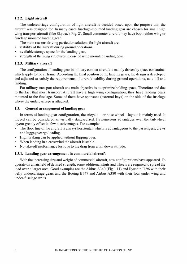
1.2.2. Light�aircraft
The undercarriage configuration of light aircraft is decided based upon the purpose that the
aircraft was designed for. In many cases fuselage-mounted landing gear are chosen for small high
wing transport aircraft (like Skytruck Fig. 2). Small commuter aircraft may have both: either wing or
fuselage mounted landing gear.
The main reasons driving particular solutions for light aircraft are:
• stability of the aircraft during ground operations,
• available storage space for the landing gear,
• strength of the wing structures in case of wing mounted landing gear.
1.2.3. Military�aircraft
The configuration of landing gear in military combat aircraft is mainly driven by space constraints
which apply to the airframe. According the final position of the landing gears, the design is developed
and adjusted to satisfy the requirements of aircraft stability during ground operations, take-off and
landing.
For military transport aircraft one main objective is to optimize holding space. Therefore and due
to the fact that most transport Aircraft have a high wing configuration, they have landing gears
mounted to the fuselage. Some of them have sponsons (external bays) on the side of the fuselage
where the undercarriage is attached.
1.3. General�arrangement�of�landing�gear
In terms of landing gear configuration, the tricycle – or nose wheel – layout is mainly used. It
indeed can be considered as virtually standardized. Its numerous advantages over the tail-wheel
layout greatly offset its few disadvantages. For example:
• The floor line of the aircraft is always horizontal, which is advantageous to the passengers, crews
and luggage/cargo loading.
• High braking can be applied without flipping over.
• When landing in a crosswind the aircraft is stable.
• No take-off performance lost due to the drag from a tail down attitude.
1.3.1. Landing�gear arrangement�in�commercial�aircraft
With the increasing size and weight of commercial aircraft, new configurations have appeared. To
operate on an airfield of defined strength, some additional struts and wheels are required to spread the
load over a larger area. Good examples are the Airbus A340 (Fig 1.11) and Ilyushin Il-96 with their
belly undercarriage gears and the Boeing B747 and Airbus A380 with their four under-wing and
under-fuselage struts.

State of the art in Landing gear .... 9
Fig. 11. Airbus A340
The arrangement of wheels, their number and pattern vary from one aircraft to another. However
most aircraft have typical configurations as listed below (Fig. 12):
• Dual arrangement for nose landing gear.
• Dual, dual tandem or tri-twin tandem for main landing gear.
Fig. 12. Main types of wheels arrangement

10 tranSactionS of the inStitUte of aViation no. 181
1.3.2. Landing�gear�arrangement�in�light�aircraft
Airplanes of the light category have landing gear that is designed to cover two basic criteria: low
mass of landing gear structure and low cost of manufacturing. Therefore it is a very important
directive of the design process to aim towards simplicity of the product. An important feature of the
small aircraft design is also its maximum air speed. Depending on the maximum speed, designers
have to decide between retractable or fixed configuration of the landing gear. Another aspect that must
be taken into account during the design process is the kind of runway surfaces that the airplane is
going to be operated off. Different requirements must be considered in case of paved or unpaved
airfields.
The factors mentioned above determine a basic layout and allow choosing a landing gear system
as well as elements responsible for energy absorption, which are essential for the landing gear per-
formance. Most common for light aircraft is also the tricycle landing gear layout but with single wheel
per strut only.
1.3.3. Landing�gear�arrangement�in�military�aircraft
Typically in military combat aircraft the following layout for landing gear is used:
• single wheel for main landing gear,
• single or twin wheels for nose landing gear.
The most common reason of using the single wheel configuration in MLG in combat aircraft is
lack of space where the landing gear bay may be placed. Nevertheless there are exceptions from that,
especially within the Russian Military Aircraft.
Military transport aircraft have usually also a tricycle configuration where the nose landing gear
is a twin wheel and main landing gear is mounted on both sides of the fuselage in dual tandem or tri-
twin tandem configurations.
Specific conditions may drive exceptional solutions in undercarriage layout. An example of an
unusual configuration of landing gear is the American strategic-bomber B-52 (Fig. 13): A solution
was realized where main and nose landing gear of the airplane is placed on the basis of an rectangle,
which allows to open the whole length of the fuselage to release the bomb-load without a shift of the
C of G in x-direction, which would force the aircraft in a dangerous nose-up or -down attitude.
This kind of arrangement required to mount additional small gear to the wing tips to ensure the
stability of the aircraft during ground operations.
One main aim for landing gear layout of heavy military transport aircraft is spreading the wheel-
load to satisfy limitations in strength of airfields. This leads to configurations like on C-5 Galaxy (Fig.
13) Transport aircraft that has a main landing gear in twin delta tandem configuration and a nose
landing gear with double dual wheel configuration.

State of the art in Landing gear .... 11
Fig. 13. Undercarriages of B52 and C-5 Galaxy transport aircraft
1.4. Landing�gear�types
Basically two different types of landing gears are used:
• cantilever gear (Figs 14 to 16),
• trailing arm suspension gear (Fig. 17).
The cantilever configuration is the most widely used and is the most cost and weight effective. In
this configuration the shock absorber is a part of the main fitting. It is a structural part. This config-
uration has however one main disadvantage. During spin-up, the shock absorber works in bending
mode what induces high bearing friction.

12 tranSactionS of the inStitUte of aViation no. 181
Fig. 15. Airbus A340 Main Landing Gear
– shock absorber
– main strut
Fig. 14. Nose retractable cantilever type landing gear for
light aircraft – 3D model

State of the art in Landing gear .... 13
The trailing arm suspension(Fig. 17) is less common for commercial airplanes and, above all, it is
heavier. It is used when ground clearance is low and stowage room limited and to get a smoother taxi
ride over bumpy runways, which makes it predestined for Military Transport aircraft like C160 or
A400M. The shock absorber is mounted between the main strut and the trailing arm. A long stroke is
obtained for relatively short leg length
Fig. 16. Main retractable cantilever type
landing gear for light aircraft – 3D model
Fig. 17. Bombardier Global Express main landing gear
a) shock absorber
b) main strut

14 tranSactionS of the inStitUte of aViation no. 181
However, in some cases, centre of gravity positions and attachment points are incompatible with
a cantilever gear and the trailing arm landing gear imposes itself as the unique available solution.
2. SHOCK ABSORBERS
The main functions of the landing gear are:
• to absorb the kinetic energy of the vertical velocity,
• to provide elastic suspension during taxiing and ground manoeuvres.
These tasks are fulfilled on landing gear by the shock absorbers and the tyres, the later will not be
covered in this document.
Several different designs exist to perform those functions.
In modern light airplanes elements responsible for energy absorption can be chosen from the
following solutions: spring beams (spring landing gear – Fig. 18), flexible elements - elastomers (Fig.
19), steel ring springs (Fig. 20) and ole-pneumatic shock absorbers, as presented below.
Fig. 19. Retractable landing gear with
spring rubber elements
Fig. 18. Spring type
non-retractable lan -
ding gear

State of the art in Landing gear .... 15
Fig. 20. Non-retractable landing gear landing gear with steel ring spring
The solutions mentioned above are preferred because of their low cost, reliability, low weight and
high efficiency rates.
A comparison of different types of „energy absorbers” is presented in Fig. 21 and Fig. 22
(according to Norman S. Currey – „Landing Gear Design: Principles and Practices”).
Although the remaining solutions are not as efficient as oleo-pneumatic shock absorbers, they are
in use because of low costs of production and low costs of maintenance.
Fig. 21. Shock absorbers efficiency – differences

16 tranSactionS of the inStitUte of aViation no. 181
Fig. 22. Shock absorbers efficiency - differences in accordance to masses of amortization system
In military and commercial aircraft where efficiency is the highest priority, only the oleo
pneumatic shock absorbers are used.
However, only one is used on FAR 25 commercial aircraft. All the modern transport aircraft have
an oleo-pneumatic shock absorber. This shock absorber type has the highest efficiency and the best
energy dissipation. Its role is to limit the impact loads by transmitting the lowest and most bearable
acceleration level to the aircraft structure and passengers. An oleo-pneumatic shock absorber absorbs
energy by „pushing” a volume of hydraulic fluid against a volume of gas (nitrogen or dry air) and
compressing it.
Oleo-pneumatic shock absorbers carry out two functions:
• a spring or stiffness function, which provides the elastic suspension by the compression of a gas
volume,
• a damping function, which dissipates energy by forcing hydraulic fluid through one or more small
orifices.
Oleo-pneumatic shock absorbers applied in contemporary airplanes can be classified in 3 different
groups
A. Depending on piston position
– piston in up position
– piston in down position
B. Depending on separation of liquid and gas
– without separation
– with separation
C. Depending on number of chambers
– single acting shock absorbers
– double acting shock absorbers

State of the art in Landing gear .... 17
According�to�group�A
Fig. 23. Shock absorber with piston in up side position
Fig. 24. Shock absorber with piston in down position
Shock absorbers with piston in lower position (Fig.
24) are applied in trailing arm type and in cantilever type
of landing gear. The inside gas chamber can be bigger and
it gives more possibility of optimizing filling of shock
absorber (liquid and gas). This is the only type of shock
absorber used in cantilever gears.
Shock absorbers with piston in upper position (Fig.
23) are applied only in trailing arm type of landing gear.
Sometimes it is necessary to locate shock absorber as
close as possible to the leg. The diameter of the piston is
smaller than diameter of cylinder and this fact allow
reaching the design target.

18 tranSactionS of the inStitUte of aViation no. 181
According�to�group�B
Fig. 25. Shock absorber without liquid and oil separated
Fig. 26. Shock absorber with liquid and oil separation
Shock absorbers in which liquid and gas are separated
(Fig. 26) are sometimes applied in small airplanes, but it
is related with higher cost of production and a little higher
total mass of the structure.
Their functional characteristics are repeatable.
Shock absorbers in which liquid and gas are not
separated (Fig. 25) are the most popular in small airplanes
because of lower costs and more simplicity (no additional
pistons with seals).
But such shock absorbers have characteristics that are
not repeatable, because of oil and gas mixing during
operation.

State of the art in Landing gear .... 19
According�to�group�C
Fig. 27. Single-Stage shock absorber
Fig. 28. Double - Stage shock absorber
Double Stage shock absorbers (Fig. 28) are applied in
airplanes, where improving of shock absorption charac-
teristics during taxing conditions over unpaved or rough
fields is required.
They have two gas chambers:
– primary chamber with lower pressure with or without
separation liquid and gas,
– secondary chamber with higher pressure always with
separation liquid and gas.
The separation is realized by separator piston (floating
piston).
Single-stage shock absorbers (Fig. 27) are mostly used
on airplanes, because of lower cost of production and
more simplicity (no additional piston, seals etc.) and less
total mass. They have only one chamber of gas.

20 tranSactionS of the inStitUte of aViation no. 181
Figure 29 shows a typical shock absorber load-stroke curve. The shock absorber load can be
divided into two parts:
- one from the hydraulic fluid forced through the damping orifices (Fdamping)
- an other from the gas, typically nitrogen, compression (Fair)
Fig. 29. Shock absorber load versus stroke law
From Figure 29, we can define one of the shock absorber characteristics, the shock absorber
efficiency. It is obtained using the following formula:
where
W is the energy absorbed by the shock absorber during its stroke,
Fmax is the maximum load,
Lmax is the maximum stroke.
With oleo-pneumatic shock absorbers, 0.8-efficiency can be easily achieved. With stroke-variable
damping, efficiencies greater than 0.85 and even above 0.9 can be reached. However the research of
the best efficiency is not necessarily the criterion of optimization for the structure.
The single-stage shock absorber is the preferred one. It is more weight and cost effective, easier
to manufacture and more reliable. However, in some particular cases, a second chamber is needed to
perform more advanced gas law.
These cases are:
– improved characteristics during taxi conditions over rough or unpaved runways,
– low attitude variations, whatever weight and balance are.
Among double-stage shock absorbers, we can again distinguish two categories according to the
respective positions of the two chambers: with adjacent chambers or with chambers in opposition. In
both cases, a separator piston has to be added, between the two gas chambers in the former and
between the hydraulic fluid and the lower gas chamber for the latter.
The following table presents the types of shock absorber (single-stage or double-stage) for some
airplanes of the Airbus family and examples of military aircrafts.

State of the art in Landing gear .... 21
2.1. Air-spring�function
When the shock absorber is fully extended, the volume occupied by the gas, under an initial
pressure p0, is V0. Those first values define the shock absorber threshold load F0 = p0S, where S is the
piston area. On one hand this spring pre-load has to be as low as possible in order to minimise forces
needed to initiate the shock absorber closure (soft landing). On the other hand it can’t be too low to
give some stiffness to the landing gear when retracted. The stiffness, as shown on Figure 30, is not a
constant with respect to the piston stroke.
This spring function is ruled by the ideal gas equation
PV = nRT
and defined by the gas curve.
For a given stroke, the following relation gives the „air effort”
with

22 tranSactionS of the inStitUte of aViation no. 181
Fig. 30. Isothermal gas curve
Values�of�g
– Under static loads and/or during ground operations, we consider slow displacements.
Isothermal air spring law is used (g =�1).
– For the landing impact, quick displacements are considered
1) with a separator piston between the air and hydraulic fluid, g =�1.3
2) without a separator piston, g =1.1 (hydraulic fluid cools the nitrogen down)
– during hard braking
1) for a main landing gear g =1
2) for a nose landing gear
• with a separator piston g =1.2
• without g =1.1
These values are only presented here to give an order of magnitude. The thermo dynamical phe-
nomenon is more complex and the value of g depends on several other parameters.
2.2. Air�spring�tuning
Before tuning this function, two parameters have to be defined, the maximum mechanical stroke
and the shock absorber section.
The FAA and EASA require that a transport-type aircraft be able to withstand the shock of a lan -
ding at 3.05 m · s-1 (10 ft.s-1) at the design landing weight and 1.83 m · s-1 at maximum gross weight.
At the limit sink rate (3.05 m · s-1), the airframe manufacturer limits the load factor. This maximum
load gives the maximum mechanical stroke.
where
Fvmax the maximum load,
W the energy to be absorbed by the shock absorber,
MR the considered mass,
Vz the vertical velocity,
l the maximum mechanical stroke.

State of the art in Landing gear .... 23
Moreover, this stroke had to be sufficient to ensure no abutment during ultimate sinking speed test
(3.65 m · s-1, 12 ft · s-1).
The shock absorber section is such as the pressure does not exceed a given pressure (typically
around 200 bars) under maximum static load. Under maximum dynamic load, the maximum pressure
is checked. The shock absorber section is a trade-off between size and weight.
When these values are fixed, several conditions and constraints are used to size the gas chamber.
These constraints depend on the position and the role of the concerned shock absorber. For example,
for FAR 25-type aircraft, „flat” air curves, but not too flat to avoid large roll excursions, are searched
to improve the comfort during taxi conditions.
The sizing of a shock absorber is based on a trade-off process. The commonest initial assumptions
are typically:
– a ratio of the static stroke divided by the total stroke between 0.60 and 0.65 for a nose landing gear
(NLG),
– a ratio of the static stroke divided by the total stroke between 0.80 and 0.85 for a main landing gear
(MLG).
Considering these constraints, two load-stroke curves for the spring function can be drawn:
isothermal and polytrophic. They will be shown for single and double-stage shock absorbers in the
next paragraphs.
2.3. Single-stage�shock�absorber
The following shock absorber (Fig. 31) is representative of a single-stage shock absorber with
metering pin and no separator piston.
Fig. 31. Airbus A320 nose landing gear shock absorber

24 tranSactionS of the inStitUte of aViation no. 181
Fig. 32. Isothermal and polytropic gas curve for a single-stage shock absorber
2.4. Double-stage�shock�absorber
Fig. 33. Airbus A340 central landing gear shock absorber

State of the art in Landing gear .... 25
For isothermal working the low-pressure chamber works alone for 50 to 65% of the shock
absorber stroke.
If low variations of aircraft attitude and/or increased stability (case 1) are looked for, then static
loads will be positioned on the low-pressure air curve. The pre-load pressure of the second chamber
will be typically chosen equal to 1.25 or 1.3 times the maximum static load.
If an aircraft is to be operated on rough and unpaved runways (case 2), static loads will be placed
on the second part of the gas curve (where the two chambers are working) – Fig. 34. With this
adjustment, we obtain an increased flexibility and a reduction of the load variations from the crossing
of obstacles. The high-pressure chamber pre-load is typically chosen around the minimum static load
(+10%). Thus it could be taken around 40% of the total stroke of the shock absorber.
Fig. 34. Isothermal and polytropic gas curve for a double-stage shock absorber
2.5. Damping�function
The damping function dissipates the kinetic energy of the vertical velocity in form of heat by
forcing hydraulic fluid through small orifices. The pressure loss created by these orifices is pro-
portional to the square of the shock absorber compression velocity. The hydraulic damping force can
be written
where
r is the hydraulic fluid density
SH is the hydraulic section area of the shock absorber
s is the orifice area
Paper and, more and more, computer drop tests are performed to size orifices to achieve energy
absorption requirements. Many rules of thumb exist for guessing orifice area.
The results are then checked with actual drop tests and refined. The usual way is to change at least
once the orifice definition after the tests.
Constant orifice design is today limited for efficiency. Metering pins are then introduced to
improve efficiency and carry out position dependant damping. The damping is then a function of the
stroke. The metering pin is sized to give high damping on initial closure then shaped to a profile that
provides optimal performance for the critical case (limit landing speed). A metering pin is in the

26 tranSactionS of the inStitUte of aViation no. 181
Airbus A320 nose landing gear shock absorber. Another used design is the „Piccolo tube” (see A340
CLG). It can provide several levels of damping with orifices that increase the damping with stroke.
The damping function is also active during the recoil of the landing gear. The energy to be
absorbed when recoiling is much less than during the impact. It is only due to the spring effect of the
compressed gas. However tuning is more difficult than for impact. The nitrogen forcing the hydraulic
fluid to flow back into its chamber or into a recoil chamber through recoil orifices damps the rebound.
If hydraulic fluid is able to flow back quickly, the aircraft will bounce upward. If it flows back too
slowly, a short wavelength bump will not be damped and high loads will appear. The recoil orifice
area is typically smaller than the impact orifice area. When recoiling, the hydraulic fluid flow often
flattens valve plates against the damping piston to partially close the orifices. Moreover some shock
absorbers achieve a recoil control by using some annulus chamber between the main fitting and the
sliding tube.
2.6. Materials
In this paragraph we discuss materials used to manufacture the shock absorbers and more
generally the landing gear. Like for all the aeronautical equipment, landing gear materials have to be
of high strength and high stiffness. But they also must have low cost and density. Some other
requirements have to be completed.
Landing gears for airplanes with oleo-pneumatic shock absorbers in most solutions are made of
metals like: steel, aluminum alloys or titanium alloys. Used are high strength steels with tensile
strength from 1200 to 2000 MPa. For not welded parts, steels are used with higher then 1500 MPa
tensile strength, such as steel 4340, 300M, NC310, 35NCD16, AerMet 100, and for welding (mostly
common on small aircraft) the most popular – steel 4330V. In shock absorbers, such parts are made
of steel: pistons, inner tubes, cylinders, pins, bolts.
A lot of parts are made of aluminum alloys that are also applied in landing gear structures. The
most common landing gear aluminum alloys are 7175, 7050, 7049, 7155, and 7010. The tensile
strength is about 450 MPa with elongation higher then 7%.
Recently titanium alloys are more often used for landing gears/shock absorbers production. The
most popular are WT23, Ti-6A1-6V-2Sn, Ti-10-2-3, Ti-4-4-2, Ti-6-22-22. Titanium alloys offer good
relation between strength and weight, but due to difficult manufacturing and machining processes,
they are not in broad use yet.
At present producers of high strength steel, aluminum alloys and titanium alloys offer a lot of
good materials for landing gears / shock absorbers production. Manufacturers of landing gears should
pay special attention to:
– stress corrosion resistance,
– low/high cycle fatigue strength,
– high cycle fatigue strength,
– weldability,
– crack initiation, propagation behavior,
– forgeability,
– machinability,
– and to production processes themselves.
Besides the traditional materials military industry is trying to reduce weight of their airplanes with
new technologies like Metal Matrix Composites. The composites are metals that are locally
reinforced with fibres, particles or other forms of reinforcement (Fig. 35, 36).
For the highly loaded landing gear components, Titanium (Ti) with continuous Silicon Carbide
(SiC) fibres provide an optimal combination. This variant is called TMC (Titanium Matrix
Composite). Especially in stiffness driven applications this leads to extreme weight savings, because
of the high stiffness to weight ratio. The fibre material SCS-6 is manufactured using a CVD process,

State of the art in Landing gear .... 27
depositing SiC on a carbon core. Titanium 6Al-4Sn-2Zr- 4Mo was chosen as a matrix material. The
fibres and matrix were combined using Plasma Spray process, resulting in tapes with longitudinal
fibres at well defined distances. Layers of these tapes were stacked and consolidated in a HIP (Hot
Isostatic Press) to form the basic material for machining.
Using the MMC can result in large weight savings compared to Ultra high strength steel parts.
Over 40% weight reduction was achieved on the F16 lower drag brace, where the material was
primarily tested. Additionally this material has many advantages due to its better corrosion and
fatigue resistance in comparison to commonly used steel and aluminium alloys.
Fig. 35. SEM (Scanning Elecron Microscopy) picture of TMC coupon fracture surface
Fig. 36. Fracture and failure mode analysis of coupons. The SCS-6 fibers are clearly visible, as well as the
fractured titanium matrix

28 tranSactionS of the inStitUte of aViation no. 181
3. LOADS
3.1. Overview
A landing gear has mainly to withstand two types of loads: the landing impact loads and the
ground operation loads. The landing conditions themselves are critical for only a small part of the
landing gear structure. Taxiing, turning and pivoting are critical for the majority of the structure.
The major part of the loads affecting a landing gear is dynamic. Static loads are only used to check
shock absorber internal pressure and flotation requirements.
Concerning the fatigue, landing gears are designed according to the safe-life approach, redun-
dancies are difficult to obtain for obvious reasons like mass or space constrains. Therefore the
selected materials usually have to present the best fatigue behaviour. To reduce the probability of
fatigue failures to a minimum, inspection techniques and frequencies are defined.
The critical load conditions can be classified into three categories:
Critical�landing�load�conditions
• maximum sink speed landing,
– tail landing,
– level landing,
•landing with a burst tyre (associated to lower sinking speeds),
•lateral drift landing.
Critical�ground�handling�load�conditions
• towing/push-back,
• taxiing,
• braking,
• turning/pivoting,
• jacking.
Other�critical�load�conditions
• loads from shimmy (has to be avoided)
3.2. Landing�loads
To explain loads that act on a landing gear, different test results will be showed. The tested gear is
a cantilever type one representative of a FAR 25-type aircraft.
The data of interest are:
• the vertical load FV1,
• the longitudinal load FH1,
• the lateral load FL1.
These loads are measured at the attachment points of the landing gear to the aircraft structure.
The vertical load (FV1 on Fig. 37), which is equal to zero at t = 0 s, increases very quickly until
0.04 s. It reaches a maximum at t = 0.3 s., when the shock absorber stroke (CAP on Fig. 38) is
maximum. The longitudinal force FH1 on Figure 37 is damped-sinus-shaped. This aspect can be
explained as follow. At t = 0 s, the wheels are motionless and come into contact with the runway.
A fric tion force is created because of slipping. This force increases as the vertical effort FV1. Under
its influence the wheels are spun up, the leg bends and stores a large amount of energy. At t = 0.2 s,
wheels are accelerated, the shock absorber bending is maximum. There is no more sliding and the
friction force goes to zero. The cantilever leg then works as a spring, oscillates at its first modal
frequency and produces a longitudinal forward force. This is the „spin-up/spring back” phenomenon.
On Figure 38, we can see that the sink rate of the shock absorber (marked in red on Fig. 38, i.e.
first derivative of the shock absorber displacement [CAP]) is nearly constant until 0.2 s. Between 0.2
and 0.32 s (light blue zone), the sink rate decreases and tends towards zero. The load is then only
pneumatic.

State of the art in Landing gear .... 29
Fig. 37. Loads during impact
Fig. 38. Displacement during impact (shock absorber stroke versus time)

30 tranSactionS of the inStitUte of aViation no. 181
Fig. 39. Spin-up
Fig. 40. Spring back
This load case is one of the design drivers considered for the sizing of several parts, like: main
fitting, sliding tube, side stay, torque links.
Figure 41 displays the results of a drop test for a main landing gear of a small aircraft conducted
for two attitudes. It shows that the process of dissipating energy has a significantly different character
depending on the pitch angle during landing.
„Spring�back”�load�=�0.8�„Spin-up”�load

State of the art in Landing gear .... 31
Fig. 41. Results of a main landing gear drop test shown for two attitudes (data – Institute of Aviation,
Warsaw)
During the design phase, limit landing loads are calculated according to the following process.
• Calculation of limit loads for some basic cases, e.g. symmetrical landing. FAR 25 regulations or
MIL-Standard provide standard coefficients to compute loads in other cases, such as drift landing,
from these initial values.
• The calculated loads are then cross-checked by representative tests.
3.3. Ground�loads
In this paragra ph, the FAR 25 requirements for the four main critical ground load conditions will
be summed up: high speed taxiing, braking, turning and pivoting. These ground operations lead to
critical static and fatigue loads for large MLG. They are the main drivers for large parts of the design.
Therefore there is a need for evaluating manoeuvring loads through rational exploitation of in-service
data statistics.
3.3.1. Taxiing
Taxiing, especially at high speed, induces high loads on landing gears and aircraft structures. So
the critical condition generally appears in take-off configuration. When on the runway, each landing
gear strut undergoes incremental loads with respect to its static load.
The FAR25 or CS25 requirements are the following:
The shock absorbing mechanism may not damage the structure of the airplane when the aeroplane
is taxied on the roughest ground that may reasonably be expected in normal operation. (25.235)
Within the range of appropriate ground speeds and approved weights, the aeroplane structure and
landing gear are assumed to be subjected to loads not less than those obtained when the aircraft is
operating over the roughest ground that may reasonably be expected in normal operation. (25.491)
This vague text is completed by an additional paragraph in CS 25.
• For the main landing gear, the loads are:

32 tranSactionS of the inStitUte of aViation no. 181
where
Z is the vertical force
Y is the lateral force
X is the drag force
Mto is the take-off mass
• For all the gears, a case for which the vertical load on each strut is equal to 1,7 times the static load
at MTOW (Maximum Take-Off Weight) with the engine thrust taken into account has to be
studied.
3.3.2. Braking
Braking is a significant source of dynamic loads. For several components of the landing gear, it is
even often dimensioning, mainly for the NLG due to the pitching effect. Basically for all aircraft,
brakes are typically mounted on the main landing gears (except some military aircraft). A strong brake
application generates a pitch-down torque. The latter creates a very significant load on the nose
landing gear. This dynamic load is usually a design driver for vertical loads, or if asymmetric braking
is considered also for side loads. Loads created by braking are in most cases more severe than those
created during derotation. This is of course specific for the NLG.
According to FAR & CS 25, three load cases have to be considered.
• Dynamic braking:
Vertical loads and drag loads equal to 0.8 time the vertical are applied. The aircraft sustains a load
factor of 1.2 at landing weight and 1 at take-off weight.
• Asymmetrical braking:
It concerns the nose landing gear. A lateral load equal to 0.8 times the vertical load is applied.
3.3.3. Turning
To curve the aircraft trajectory, centripetal forces are needed. These appear thanks to the drift of
the tyres, which generates lateral loads. They are proportional to the centrifugal acceleration. It is
generally admitted that they are distributed on the level of each tyre proportionally to the local vertical
reaction.
The most loaded landing gear is the one outside the turn. Turning at high speed is often dimen-
sioning for the main landing gears.
3.3.4. Pivoting
Pivoting is a turn carried out at very low speed, with a very small radius. The minimum radius of
the turn is obtained while pivoting around one of the main landing gears which wheels are braked.
The resulting movement being very slow, the yaw torque is balanced by a moment of vertical axis,
which appears by friction between the tyres and the ground.
Pivoting induces lateral and torsion loads.
3.3.5. Shimmy
Shimmy is the one thing to be avoided on landing gears. It is sinusoidal, combined lateral yaw
motion of the landing gear. It comes from the interaction between the structural dynamics of the
landing gear and the dynamic tyre behaviour. The typical frequency of this phenomenon is in the
range of 10 to 30 Hz. In some cases it can become divergent. The motion amplitude then grows and
induces annoying vibrations affecting the visibility of the pilot and comfort. They can even result in
severe structural damage or landing gear collapse.

State of the art in Landing gear .... 33
3.4. Calculation�of�landing�gear�ground�loads
The loads calculation method will be presented on example of light aircraft. The ground loads
appearing during landing process (landing loads) are determined and described on the basis of FAR
23 § 23.471 to 23.483 and additionally can be calculated according to FAR 23 Appendix C.
The landing loads include limit loads with descent vertical velocity for „level“ landing conditions,
for „tail down” landing conditions and for one-wheel landing conditions.
The base for determination of the loads is the correct definition of the load factor n. This factor is
a function of the vertical velocity, vertical displacement of axle and of the wheel and tyre deflection.
If:
VZ – sink velocity,
UAW – max wheel vertical displacement,
UT – max tyre deflection,
L – lift ratio,
mR – mass of airplane reduced to landing gear,
hAW, hT – shock strut and tyre efficiency,
hWAW, hWT – displacement efficiency of shock strut and tyre,
where:
hWAW = displacement of wheel’s axle / max. displacement of wheel’s axle
hWT = deflection of tire / max. available deflection of tyre
than the energetic balance described as:
(1)
and after transformation the limit inertia load factor n is obtained.
It can be seen, that the load-factor n is not a function of mR.
The vertical ground reaction is:
In general it is an aim to minimize the load factor n but according to FAR 23 § 23.473(g) it shall
not be less than 2.67.
On the other side, the aircraft structure is designed to the inertia load factor n, which results from
the aircraft maneuvering envelope.
Resulting from (1): if the inertia load factor n decreases than the vertical displacement of the axle
and the wheel and tyre deflection increases. This can lead to the increase of landing gear parts
geometry and finally – the mass.
Limit drop velocity, which is a function of the airplane landing weight and wing surface area, is
defined in FAR 23 § 23.473(d).
Modified to SI units:
V = 0.509788 (W / S)1/4 [m/s]
where:
W – the airplane landing weight in [N]
S – wing surface area in [m2]
For light airplanes this velocity can not be less than 2.12 [m/s] not be bigger than 3.05 [m/s].
The airplane landing weight is quantified in FAR 23 § 23.473(b) and (c).
The efficiencies hAW and hT for small airplanes are:
hAW = 0.8¸0.9, (for oleo-pneumatic shock absorbers should not be less than 0.75)
hT = 0.47¸0.5

34 tranSactionS of the inStitUte of aViation no. 181
Besides limit drop energy the landing gears have to absorb reserve energy equal to 1.44 times limit
drop energy, according to FAR 23 § 23.727(a) and DEF-STAN 00-950.
To assure absorption of limit and reserve energy wheel and tyre must not bottom out. The values
should be: hWOK < 0.9 and hWOP < 0.95.
The factor of lift wing load according to FAR 23 § 23.725(b) and § 23.727(b) is:
L = 2/3 for limit drop energy,
L = 1 for reserve drop energy.
Correctness of defining above coefficients and design parameters must be confirmed during drop
tests that should be conducted according to FAR 23 § 23.725 to 727, using a proper landing gear unit
attitude.
Typical graphs of the forces generated during drop tests are shown on Figure 42 and on Figure 43.
Fig. 42. Graph of the vertical force generated during drop tests for cantilever type L/G. Limit vertical
velocity Vz = 3,05 [m/s] (data – Institute of Aviation, Warsaw)
It can be observed that the landing gear with the conventional oleo-pneumatic shock absorber,
which has the damping orifice with fixed diameter or with applying a metering pin, may be optimize
for only one drop velocity.
It is usually limit drop velocity.
For the other drop velocities efficiency of absorption can fall even to hOK = 0.5.
So, there are generated loads bigger than optimized with efficiency hOK = 0.8¸0.9.

State of the art in Landing gear .... 35
Fig. 43. Graph of the vertical force generated during drop tests for trailing arm type L/G. Limit vertical
velocity Vz = 3,05 [m/s] (data – Institute of Aviation, Warsaw)
Fig. 44. Graph of the vertical force generated during drop tests for trailing arm type L/G. Vz = 1,83 [m/s]
(data – Institute of Aviation, Warsaw)
Landings with limit drop velocities are a rather rare phenomenon that is proved by the table
quoted below. The solution we look for should be supposed to result of optimal work of the shock
absorber and to minimize load factor for each condition. This can have advantageous influence on
fatigue durability of the landing gears.

36 tranSactionS of the inStitUte of aViation no. 181
Fig. 45. Graph of the vertical forces generated during drop tests for cantilever type L/G. Vz = 2,00 [m/s]
(data – Institute of Aviation, Warsaw)
Comparison of landing impact spectra
where:
PT – privat trainer – AFS-120-73-2
SEE – single engine exec. – ”
TEE – twin engine exec. – ”
TJA – twin jet airliner – ”
MIL – field – MIL-A-8866(ASG)

State of the art in Landing gear .... 37
3.4.1. Shock�absorbers�loads
Loads�generated�during�compression�of�gas.
If:
p – gas pressure,
Ap – effective surface area of piston.
Therefore the balances of force and the pressure is:
At the same time with the change of shock absorber stroke changes of gas pressure appear as:
where
p0 – gas pressure in non compressed shock absorber
V0 – volume of gas in non compressed shock absorber
V – volume of gas in compressed shock absorber
Sp – stroke of piston
g – exponent of polytropic ( see chapter 2)
The „gas force” in shock absorber is:
and the absorbed energy is:
The�loads�generated�during�flow�of�liquid�through�orifices
If:
Dp – difference of pressures between chambers on both sides of orifice,
Vc – speed of liquid flow through a small hole (orifice),
Ap – effective surface area of piston,
Ah – area of small hole,
r – density of liquid,
Vp – velocity of piston displacement,
Pd – the load of hydraulic resistance,
m – coefficient conditioned by shape of orifice and the fluid viscosity.
Then:
Dp = (r/2)Vc2
and

38 tranSactionS of the inStitUte of aViation no. 181
The�friction�loads
The friction loads appear between pairs of moving parts, especially between:
– head and cylinder of shock absorber,
– seals located in cylinder (no movement) and piston,
– seals located in floating piston and the inside area of the cylinder or of the piston.
The loads depend on geometry of the landing gear and on pressures in the shock absorber. They
are bigger in cantilever type of landing gear/shock absorbers then in lever type.
For the first approximation it can be assumed that friction forces are proportional to the pressure
of gas inside of a shock absorber:
For cantilever type landing gears k can be assumed: k = 0,1¸0,15
For lever type of landing gears k can be assumed: k = 0,06¸0,08
The�total�load
The total load generated by a shock absorber is the sum of all above described forces, so:
P shock absorber = Pg + Pd + Pfr
4. ADDITIONAL REQUIREMENTS
4.1. Introduction
Landing gear used in airplanes certified according to FAR, respectively EASA CS or military
standards must be capable of meeting requirements described in above regulations as well as special
requirements determined by the airframer (aircraft requirements).
Additional requirements include environmental specifications and durability criteria.
4.1.1. Environmental�requirements
Shock absorber should be capable of operating and/or being stored within environmental con-
ditions under ambient parameters and in increased critical conditions.
The covering environmental conditions are specified in EUROCAE ED-14C/ RTCA DO-160C
(1989) and RTCA/DO-160D (1997) standard “Environmental conditions and test procedures for
airborne equipment” as well as in MIL-STD 810.
Ambient�conditions:
These standards specify ambient conditions as:
– Temperature: +15 to +35 degrees Celsius with tolerances ±3 degrees Celsius.
– Relative humidity: not greater them 85 percent.
– Ambient pressure: 84 to 107 kPa with tolerances ±5 percent of specified pressure.
Temperatures
One of the most important parameters is the operating temperature. Critical items in Shock
Absorbers are seals. They should be tested in the Shock Absorber Assembly for the specified tem-
perature ranges.
Depending on the type of aircraft – the landing gears can be attributed to equipment categories.
The categories cover the range of environments known to exist in the majority of aircraft types
and the locations where landing gears are installed.
The categories related to landing gears are:
– B2–for installation in non - pressurized and non controlled temperature locations on airplane that
is operated at altitudes up to 7 620 m (25 000ft) MSL.

State of the art in Landing gear .... 39
– C2–for installation in non - pressurized and non controlled temperature locations on airplane that
is operated at altitudes up to 10 700 m (35 000ft) MSL.
– D2–for installation in non - pressurized and non controlled temperature locations on airplane that
is operated at altitudes up to 15 200 m (50 000ft) MSL.
The temperature conditions connected with above categories are presented in the table below:
The rates applicable to the temperature variation are minimum 10 degrees Celsius per minute.
According to the applicable requirements and standards special tests should be conducted. The
methodology of tests are specify in RTCA/DO-160D.
Humidity/Corrosion
Another problem is connected with humidity. Tests should determine the ability of landing
gears/shock absorbers to withstand either natural or induced humid atmospheres.
The main effect to be anticipated is corrosion, especially for airplanes that are in service in
maritime environment.
According to the category landing gears may be required to be operated under conditions that are
subjected to direct contact with outside air for periods of time in excess of that specified for the
standard humidity environment.
The moisture should be provided by steam or by evaporation of water having a pH value between
6.5 and 7.5. Figure 46 shows an external humidity environment test.
Fig. 46. External humidity enviroment test

40 tranSactionS of the inStitUte of aViation no. 181
The total test includes 6 cycles (144 hours of exposure). The Shock Absorber structure should be
capable of providing resistance to corrosion during and after exposure to humidity up to 100% in a
salty environment. It should include conditions with condensation of liquid and/or frost. All parts of
Shock Absorbers have to be protected against corrosion.
Ozone
Shock absorber exposed to ozone have to withstand without deterioration. Usually this
requirement is applied for non retractable L/G.
Fungus�resistance
Aircraft equipment should not support fungal growth and any fungal growth should affect per-
formance or use of the material. The primary objectives of the fungus test are to determine:
a. if the materials comprising the material, or the assembled combination of same, will support
fungal growth, and if so, of what species,
b. how rapidly fungus will grow on the materiel,
c. how fungus affects the materiel, its mission, and its safety for use following the growth of fungus
on the material,
d. if the materiel can be stored effectively in a field environment,
e. if there are simple reversal processes, e.g., wiping off fungal growth.
Sand�and�dust
Landing gears are installed in locations where the equipment is subjected to blowing sand und
dust carried by air movement at moderate speeds. The main adverse effects to be anticipated in such
conditions are:
– penetration into cracks, bearings and joints, causing interferences and,
– clogging of moving parts,
– this might act as nucleus for the collection of water vapour, resulting in a secondary effect of
possible corrosion.
Sand and dust used in a suitable test chamber vented to the atmosphere shall be raised and
maintained at concentration of 3.5 to 8.8 g/m3. The jet velocity shall be maintained between 0.5 and
2.5 m/s. Special scrapers have to be applied to exclude sand and dust from moving parts (pistons,
bearings, etc.). The structure of shock absorbers have to work without getting stuck during contact
with sand and/or dust.
Rain
Aircraft equipment should be resistant with respect to rain, water spray, or dripping water. The
features that should be checked are:
a. the effectiveness of protective covers, cases, and seals in preventing the penetration of water into
the material.
b. the capability of the material to satisfy its performance requirements during and after exposure to
water,
c. any physical deterioration of the material caused by the rain,
d. the effectiveness of any water removal system,
e. the effectiveness of protection offered to a packaged material.
Acoustic�noise
Materials should resist the specified acoustic environment without unacceptable degradation of its
functional performance and/or structural integrity.

State of the art in Landing gear .... 41
Mechanical�shock
Materials should physically and functionally withstand the relatively infrequent, nonrepetitive
shocks encountered in handling, transportation, and service environments.
Accelerations
Equipment of military aircraft should structurally withstand the steady state inertia loads that are
induced by platform acceleration, and manoeuvre in the service environment and function without
degradation. The acceleration level that military equipment has to withstand is up to 15g, depend on
the role of the aircraft.
Temperature�shock
Materials should withstand sudden changes in the temperature of the surrounding atmosphere
without experiencing physical damage or deterioration in performance. For the purpose of military
applications „sudden changes” is defined as „greater than 10°C per minute”.
Electromagnetic�compatibility
The equipment shall be designed such that electromagnetic radiation originating from internal or
external sources does not influence the correct function of the equipment nor shall the equipment
influence other equipments.
Equipment should be tested for:
– conducted/radiated susceptibility,
– magnetic induction fields susceptibility,
– lightning strike.
Environment�friendly�materials
Today some materials or treatments are harmful for the environment and health. Some industry-
wide developments to find replacement technologies are on their way. One of the best examples is the
effort done to replace cadmium and chrome plating with alternative surface treatments.
Cadmium is used on many landing gear parts to provide protection against corrosion. Chrome is
used to improve friction/wear properties as well as corrosion. Chrome itself is not toxic but the hexa -
valent chromium products found in the hard chrome plate process is. So, new processes have
appeared. The most promising is the HVOF (High Velocity Oxygenated Fuel). It uses metal ceramic
powder sprayed at very high speeds (~3000 km/h-1) onto landing gears components. It then con-
solidates to form a resistant and protective coating.
4.1.2. Other�general�requirements
Durability�/�Life�cycle
The life of an aircraft is in the order of 25 years. Equipments installed on an A/C shall sustain the
same life, with as less scheduled maintenance work as possible. For a landing gear this equates to
approximately 20.000 to 70.000 landings, depending on the use of the aircraft (long- or short haul).
Software�design
The software code for control of the active circuits must be free of errors this shall be ensured by
following the applicable software design guidelines. The software code shall contain fail safe func-
tionalities.
4.1.3. Additional�requirements�for�military�aircraft
Military Aircraft in addition what is stated above to satisfy additional requirements that result
from their purpose.

42 tranSactionS of the inStitUte of aViation no. 181
Temperatures
Landing gear equipments should not be adversely affected with following outside air tem-
peratures:
Hydraulic equipment should function for the following temperatures of hydraulic fluid:
Gunfire�vibrations
Vibrations which origin from gunfire must not damage the installed equipment.
Nuclear�hardening
The equipment shall be designed such that it functions throughout a nuclear event without any
degradations in specified performance.
Biological/chemical�(BC)�hardening
The effects of contamination by BC agents shall not cause any short term (e.g. within 4 weeks)
deterioration of materials such as to affect the equipment reliability or performance, nor shall it result
in corrosion or damage to painted surfaces.
Battle�damage
The equipment parts shall be designed to be easily salvaged after the equipment is battle damaged.
The undamaged parts/modules will be considered as spares and reutilized. A modular equipment
design should be considered
4.1.4. Additional�for�requirements�for�commercial�aircraft
Today environmental requirements take a greater and greater importance. Respecting the envi-
ronment, as well as safeguarding the health and safety are a crucial concern. There are numerous ways
to achieve these goals. We will be interested here only on two great subjects under development in the
world of the landing gears: the reduction of the noise and the elimination of some products such as
chromium VI.
Noise�reduction
Until the 1960s, engine noise dominated overall aircraft noise levels. Airframe noise was neg-
ligible by comparison and, moreover, noise wasn’t a real concern. In the early ‘70s, the introduction
of new engine technologies such as the high bypass ration turbofan led to a drastic reduction of engine
noise level. Consequently, the airframe, including the landing gear, noise component became more
important. During the approach, landing gear noise is up to one third of the total aircraft noise.
In 1971, ICAO (International Civil Aviation Organization) has adopted a series of standards and
recommended practices. Those are gathered in Chapter 16 of the ICAO convention. The current trend
is to constantly decrease the authorised noise levels.

State of the art in Landing gear .... 43
Two major work axis are studied today:
• to find ways of reducing noise generated by current landing gears. They could be modified and
fairings could be attached,
• to investigate alternative landing gear configurations with noise reduction taken as a primary
design driver.
Chrome and Cadmium are not the only materials to be deleted from landing gear parts. In the
„black list”, beryllium, nickel or VOCs (Volatile Organic Compounds) can be found.
5. TRENDS WITHIN INDUSTRY
The first remarkable trend within the world of the landing gears is the transition from the trade of
equipment manufacturer to that of system provider / system manager. The landing gear suppliers are
more and more often responsible for the system integration. The responsibility of a landing gear
supplier will now extend from the tyre on the ground to the Landing Gear selector switch inside the
cockpit.
The second way, which has been recently opened, is the introduction of smart materials and
structures. These structures will carry micro-gauges to monitor stresses, strains and other data.
Indeed, health monitoring of aging aircraft is more and more important. Those data will be useful
from a maintenance point of view. Moreover they will give an insight view of the real operational life
of a landing gear. This knowledge is very useful to create more realistic fatigue spectra.
The introduction of new materials with higher strength and toughness is also progressing. New
steels, titanium and aluminum alloys are developed just as high strength composites. Organic and
metallic matrices are both studied without distinction. The aim is always the same: to improve
material characteristics and cost/weight efficiency (refer to section 2.6 Materials for details).
Another significant evolution is the electrification of the landing gear. After a long period during
which hydraulics was the privileged source of power of aeronautics, the electric output makes a return
in strength. After a noticed return within the flight controls, the landing gear designers take interest in
its use to perform actuation and steering as well as even braking. The removal of hydraulics will lead
to an increase in safety as a flammable liquid gets banned from e.g. hot parts as brakes are.
Additional research is aimed in the following directions:
– using active control systems for controlling ground loads (ADLAND - see chapter 6),
– using the friction phenomenon in energy absorption,
– introducing more welding technologies into landing gear production process.
6. ACTIVELY CONTROLLED LANDING GEARS
Paragraphs 6.1 to 6.4 refer to a literature survey on actively controlled landing gears, paragraph 6.5
briefly reflects Messier Dowty work done on that subject.
6.1. Introduction
For many years aircraft industry considered the possibility of introduction of controlled landing
gears into airplanes. Motivation for these efforts was always depended on the branch of industry that
the research was started by. Works conducted by civil transportation research centres took the safety
of airplanes operations and passengers and crew comfort as a main aim to achieve. Military
companies were also interested in introduction of controlled landing gears into their aircraft. The most
basic motivation for military purposes were obtaining a more versatile device, which would be
capable of landing on partly destroyed or repaired landing fields and introduce less loads into the
aircraft structure.
Following the separation it was important for civil purposes to control the behavior of the nose
landing gear, which induces high frequency vibrations into the fuselage during taxiing and for
44 tranSactionS of the inStitUte of aViation no. 181
military applications main landing gears were the units that should be controlled because these work
with highest vertical and horizontal velocities during landings on uneven pavements. In the following
report the state of the art for military applications is presented.
Nowadays basically only oleo-pneumatic shock absorbers are in use, which are the most popular
because of relatively high efficiency rates that can be obtained with these. The primary aim for each
aircraft shock absorber is to dissipate kinetic impact energy by converting it into other forms of
energy. Traditional passive oleo-pneumatic shock struts transform kinetic energy of a plane into work
by forcing fluid to flow turbulently between internal chambers of the strut. The value of damping
force generated by the device, depends on difference between fluid pressures values in internal
chambers of hydraulic shock absorbers. By influencing the time characteristics of damping force, one
can regulate an amount of energy dissipated by the shock absorber. Control of internal pressures in
shock absorbers can be introduced in a number of ways: by changing of an orifice diameter through
which the fluid is forced from one chamber of shock absorber to another; by adding an external
hydraulic system connected to the chambers of shock absorber with capability of influencing the
internal pressure; and by changing the properties of fluid itself. The last possibility can be obtained
with use for example of magnetorheological fluids, which properties can be changed depending on an
applied external magnetic field.
A review of the above mentioned solutions will be presented in the following sections.
6.2. Variable�orifice�diameter
Simple and the most widely used in current designs is a shock absorber which performance
depends directly on the shock strut deflection. The dependence is obtained by introducing a so called
metering pin inside of the shock absorber housing (Fig. 26). During deflection of the device, the
metering pin fixed to the lower part of shock absorber, moves in orifice that is bored in upper part of
shock absorber. Due to the variation of pin diameter the desired course of net orifice area can be
obtained. Time characteristics of generated damping force in this kind of device are dependent only
on deflection of the piston and do not correspond to changes in velocity. That is the reason why these
are not able to react properly for wide range of landing cases e.g. for very high or very low impact
energies that may occur during landing operations. Due to the concept limitations each landing gear
must optimised for certain landing conditions, which are usually chosen as the most frequently
noticed case.
6.3. Control�of�differential�pressure�in�internal�chambers�of�the�shock�absorber
The idea of introducing active systems with capability of controlling the behaviour of landing gear
struts was considered since the 1970s [1]. Most of the propositions were based on the idea of
influencing the shock absorber performance by regulating the internal fluid pressure over time. In
reference 1 the authors present a simple classification of control systems that may be potentially used
for active control of landing gear struts. Figure 47 shows three concepts of influencing the shock
absorber forces. The first proposal is controlling the pressure level in the upper chamber by regulating
the gas pressure. In the solution two gas accumulators were mounted to the upper part of the system
and connected to the gas chamber. One of them was a low-pressure accumulator and the other was a
high-pressure accumulator. A pair of electronically controlled valves controlled a pressure difference
between both chambers to be on the required level. The second concept took into consideration
introducing an additional hydraulic actuator, which paralleled the shock strut itself. In the third
proposal the control unit was connected to the lower chamber of the shock strut and regulated the
fluid pressure level. For all cases it was considered to accomplish control by means of a digital con-
troller controlling the valves. The design that realized the idea of controlling the lower chamber fluid
pressure was reconfigured in a way shown in figure 47. Finally the researchers chose the last
approach, which they called Series Hydraulic Active Control Gear Model, for developing during
further research.

State of the art in Landing gear .... 45
Fig. 47. Active control concepts for landing gears [7]
6.4.�Control�realization�by�introducing�fluid�accumulators
J. McGhee and H. Carden published in 1976 a report [2] giving an overall layout for operating
landing systems actively controlled via using a hydraulic system connected in series to the shock strut
(Fig. 48). The following example illustrates the active control landing gear during a landing impact and
roll-out. The mass at the wing-gear interface was assumed to remain constant during landing; thus, the
acceleration of the wing-gear interface reflected the force applied at this position. For a specific
airplane design and the measured sink rate, the limit force, defined from the limit acceleration, was
determined as a product of the mass and the square of the sink rate divided by the available shock strut
stroke. A signal corresponding to the limit acceleration was input to the electronic control circuit. The
electronic control circuit continuously monitored the acceleration signal at the wing gear interface and
compared this signal with the limit acceleration signal. The control was actuated when the wing gear
accelerometer signal exceeded the acceleration limit signal by a preset tolerance.
The report of J. McGhee and R. Dreher from 1982 [3] presents results of experimental testing of
series hydraulic active control system for landing gear of small aircraft. The tests were performed on
an experimental setup that consisted of a landing gear strut with assembled apparatus for changing the
oil pressure inside of the upper chamber (Fig. 49). The apparatus contained two fluid accumulators
and a servo valve connected to the shock strut in a series configuration. The tests that were performed,
aimed on determination of the effectiveness of the existing control system. The unit was subjected to
vertical drop tests , touchdown impact tests and traversing-the-step-tests.
Results showed that, during the impact phase of a landing, the active gear was effective in
reducing ground loads applied to the simulated airplane relative to those generated by the passive
gear. Data from the vertical drop tests showed that the effectiveness of the active gear increased with
increase in touchdown sink rate. For example it was noted that the improvement was on a level of 8%
for a sink rate of 0.9 m/s and on a level 32% for a sink rate of 1.7 m/s. However, the effectiveness
decreased dramatically when a horizontal (ground) speed was increased. For example 31% of loads
reduction for ground speed of 8 knots and only 9% percent of dynamic loads reduction at 40 knots.

46 tranSactionS of the inStitUte of aViation no. 181
Fig. 48. Series hydraulic active control gear model [1]
Fig. 49. Details of McGhee strut assembly [3]

State of the art in Landing gear .... 47
These reductions in effectiveness may have been attributed due to increase in shock-strut
„stiction” (= stick and friction effects) forces resulting from increased wheel „spin up” drag at the
higher ground speeds.
The results indicated also that a hydraulic system is not fast enough to perform an efficient control
procedure during impact phase of the landing. Fig. 50 and Fig. 51 present the results of drop tests that
were performed in NASA laboratories. Figure 6.4 presents loads forces and stroke versus time. The
graph showing the forces contains three lines: a solid line describing forces obtained with using an
active gear, a dotted line describing forces obtained using a traditional landing gear and a dash-dotted
line depicting the calculated desired force limit. The drop test was conducted assuming a horizontal
velocity equal to 0 m/s so with minimal internal friction forces. It can be seen that the control unit
starts to regulate after around 50 ms from the beginning of the process and around 25 ms after
receiving control signals. This latency was too large for introduction of a closed loop control system.
Figure 51 shows results of a test with a horizontal velocity of about 40 knots. Only slight dif-
ferences between force-levels for active and passive tests proved that internal friction of the shock
strut is a very important factor influencing the behavior of the landing gear. It was concluded that a
control system for landing gears should take into account friction forces as forces acting in parallel to
the damping force generated by the shock strut.
In 1984 McGhee and Morris [4] proposed a complete control system for landing gears designated
for reducing dynamic loads transmitted to airplanes fuselages during ground operations. This
hydraulically based active system adjusted damping forces during taxiing. The system operation was
briefly described as follows. The electronic controller determined the operating mode (take-off or
landing), amplified and shaped feedback transducer signals, and implemented control laws. The
control laws programmed into the controller were based on the following logic. Assuming the
airplane mass remained constant during landing, the controller employed the sink rate to compute the
touchdown energy of the airplane. During landing impact the gear compressed as the shock strut
deflected, the hydraulic force in the shock strut increased, and the controller computed and compared
the remaining work capability of the shock strut (determined from the accelerometer and linear poten-
tiometer signals) with touch down energy. When the instantaneous work capability of the shock strut
equaled or exceeded the touch down energy, the controller stored in memory the instantaneous value
of the scaled acceleration (wing – gear interface force) for use as an impact limit force and enabled
the servo loop. This force was maintained by removal/addition of hydraulic fluid from/to the shock
strut piston.
At a programmed value of momentum, for a specific airplane gear design, the controller linearly
transitioned the impact limit force to a value of zero for rollout control. During rollout and taxi the
control maintained the wing – gear interface force within a designed tolerance about zero force. After
control initiation at touchdown, the controller continuously operated with a long time constant (10
seconds) control to return the gear stroke to the designed static equilibrium position.
By the proposed approach the authors obtained a slight decrease of touchdown loads and sig-
nificant improvement of the ground operation performance.
In 1999 NASA Langley Research Centre [5] presented results of an active landing system
developed for Navy aircraft. The main effort of the work was to propose an efficient way to solve a
problem of operating military aircrafts on repaired bomb damaged landing fields.
A prototype of active landing gear presented by the authors was based on an idea of series
hydraulic active control system proposed in 70’s. Possibility of fluctuating the pressure levels was
reached by introducing pressure accumulators connected to both: upper and lower oil chamber and
steered by electro servo valves. Figure 52 presents the general scheme of the proposed solution. The
idea of influencing both upper and lower chamber simultaneously might have come from problems
with operational delays that were determined by previous research.
The goal for control design was to minimize disturbance propagation from the ground into the
fuselage. The control law was realized by means of steering the electronic valves.

48 tranSactionS of the inStitUte of aViation no. 181
Fig. 50. Series hydraulic active landing gear – drop tests results
Fig. 51. Series hydraulic active landing gear – drop tests results

State of the art in Landing gear .... 49
Experiments were conducted on a typical landing gear, which was modified in a number of ways.
Two electro hydraulic servo valves were attached to lower and upper chamber of the landing gear in
a way, which enabled them to transfer pressurized fluid either into or out of the desired chamber. Both
valves were designed to have flow-rates of at least 26 gal/min (98¸42 l/min) at 600 psi (4.137 MPa)
with a response approaching 100 Hz. A high-pressure accumulator was mounted on the upper mass
and was kept charged to a pressure approximately twice that of the static pressure in the landing gear.
A low pressure accumulator was also installed in a way that when desired, pressurized hydraulic fluid
in the landing gear could be directed there, reducing the transient back pressure that would tend to
restrict the outward flow of the hydraulic fluid. The low- pressure accumulator was maintained at
essentially atmospheric pressure. Ultimately the low-pressure accumulator was attached to an
atmospheric pressure reservoir where the pump used to supply high pressure accumulator was
located. The system was then pressure balanced evenly around the nominal static pressure of the
landing gear, permitting roughly equal flow rates into or out of the gear at similar servo command
levels. The piston head of the shock absorber was modified in order to obtain the same damping char-
acteristics for both directions of the fluid motion. Control of the system was performed in a closed
loop routine.
As a result authors obtained reduction of accelerations of a suspended mass by a factor of 4 with
the proposed methodology. The control of impact forces was not performed.
Fig. 52. Scheme of active landing gear system

50 tranSactionS of the inStitUte of aViation no. 181
6.5. Research�at�Messier�Dowty
Three main programs dealt with active control of shock absorbers within Messier-Dowty. All three
were based on the Dassault Mirage 2000 size fighter aircraft (Fig. 53) and carried out between 1984
and 1995.
Fig. 53. Mirage 2000
In detail the programs were split like shown below:
1. MLG with active control (1984¸1987).
2. Adaptive NLG (1990).
3. Optimized double stage shock absorber (1995).
Ad.�1)
The shock absorber functionality was controlled by modifying the diameter of the orifices
between oil and gas chamber. The control was realized by use of a servo valve (Fig. 54).
118 different tests have been conducted (landing impact tests and the crossing of obstacles with
fixed and variable orifice area) at CEAT test facilities in Toulouse. The results obtained showed that
the predominating factor for optimization is rather the stiffness than the damping shock absorber and
that a continuous control of the stiffness requires very significant hydraulic power. The load-reduction
obtained during the tests was negligible, even though the hydraulic, mechanic and electrical portion
of the system worked well.

State of the art in Landing gear .... 51
Fig. 54. Shock absorber with controll (servo valve)

52 tranSactionS of the inStitUte of aViation no. 181
Ad.�2)
The NLG was designed (based on the outcome of the above experience) in such a way, that the
pilot could switch the unit form a single stage functionality (during landing impact – spring curve I
(Fig. 55)) to a double stage functionality for take-off and/or taxi on unprepared or repaired runways
(spring curve II (Fig. 55)). In case of a failure the system would still act as a traditional shock absorber
(fail-safe).
Advantages were gained for taxiing and ground handling, e.g. for operation on repaired runways
a load decrease for 20% was achieved with an active NLG shock absorber, on unprepared runways
the gain was still 8%, so the operational capability of the aircraft was improved by that technology.
The disadvantages were an mass increase of about 20% and costs which were 10% higher than for
the conventional design, taking the additional hydraulic supply not into consideration.
Fig. 55. Spring curve of active NLG
Ad.�3)
Here the economic side of active control was investigated. The results are shown in the table
below:

State of the art in Landing gear .... 53
The results above illustrate that the active control can lead to a decrease in load introduction, but
it could up to now not compete with respect to mass, reliability, maintainability and costs.
REFERENCES
[1] Ross I., Flight worthy Active Control Landing Gear System for a Supersonic Aircraft, NASA
Contractor Report 3298, 1980.
[2] McGhee J.R., Carden H.D., A Mathematical Model of an Active Landing Gear for Load Control
during Impact and Roll-out, NASA Technical Note, NASA TN D-8080, 1976.
[3] McGhee J.R., Dreher R.C., Experimental Investigation of Active Loads Control for Aircraft
Landing Gear, NASA Technical Paper 2042, 1982.
[4] McGhee J. R., Morris D.L., Active Control Landing Gear for Ground Load Alleviation, AGARD
384, FMP Symposium, Toronto, Canada, 1984.
[5] Horta L.G., Daugherty R.H., Martinson V.J., Modelling and Validation of a Navy A6- Intruder
Actively Controlled Landing Gear System, Langley Research Centre, Haumpton, Virginia,
NASA/TP-1999-209124.
[6] Wang X., Carl U., Fuzzy Control of Aircraft Semi-active Landing Gear System, Proceedings of
37th AIAA Aerospace Sciences Meeting and Exhibit, Reno, 1999.
[7] Currey Norman S., Aircraft Landing Gear Design: Principles and Practices, AIAA Education
Series, 1989.