aade-04-df-ho-15: integrated well construction technology leading … · aade-04-df-ho-15...
TRANSCRIPT

AADE-04-DF-HO-15
Integrated Well Construction Technology Leading to Optimum Production R. Ashley Donaldson and Donald L. Whitfill, Halliburton
This paper was prepared for presentation at the AADE 2004 Drilling Fluids Conference, held at the Radisson Astrodome in Houston, Texas, April 6-7, 2004. This conference was sponsored by the Houston Chapter of the American Association of Drilling Engineers. The information presented in this paper does not reflect any position, claim or endorsement made or implied by the American Association of Drilling Engineers, their officers or members. Questions concerning the content of this paper should be directed to the individuals listed as author/s of this work.
Abstract
As more complex wells push the limits of drilling and completion technology, new methods should be used for optimum results. Combinations of new technologies will cross over traditional product lines. This paper discusses the application of new drilling and completion systems that can enable optimized deployment of expandable screen completions. For the study of this application and the possible effects on production of a “model” well, the authors examined several new technologies already being utilized in the field.
The objective of the study is the design and drilling of a model horizontal well that can provide the best possible borehole to help optimize production. To achieve this goal, the well is planned from the “bottom up” to enable appropriate fluid and completion selection based on reservoir constraints. A high-quality wellbore can be obtained by utilizing a matched drilling system with rotary steerable technology. A pilot hole is drilled, and then opened with a new pullback under-reamer concept, to help minimize formation damage and remove cuttings beds. The final completion employs new expandable screen technology that can provide a larger completion assembly when fully expanded. Additionally, options for final filter-cake breaking and cleanup are discussed. This integration of technology from each phase of the drilling and completion process can, in turn, lead to better production capability. Introduction
Saleri et al.1 provide an example application of some of the concepts discussed in this paper. This SPE Distinguished Author paper discusses the result from the “confluence of three recent events—maximum reservoir contact (MRC) wells, geosteering, and increasing downhole intelligence.”
MRC wells are defined as having an aggregate reservoir contact in excess of 16,000 ft through a single or multilateral configuration.2 The fundamental purpose of these wells is to achieve enhanced well productivities.
MRC wells may have a number of well geometries and differ from conventional horizontal wells in terms of both cost and time. For two example wells, the intra-reservoir portion increases from 29% in a 3,280-ft horizontal (single lateral) to 74% for an MRC well (fork trilateral). The unit-cost makeup shows a similar shift,
with intra-reservoir unit costs accounting for 62% of the total. In other words, higher productivities can be achieved through higher expenditures in the target formation on a per-drilling-dollar-spent basis.
The value-adding effect of geosteering for effective well placement, based on logging-while-drilling (LWD) and measurement-while-drilling (MWD) tools that provide downhole intelligence, create the entry tools for future development. This concept is further explored through answering the question: What improved results might be expected if a number of new tools were combined in an integrated “best-available-technology” approach to well construction?
Well Planning
To help optimize fluid selection, the well should be planned from the “bottom up”; that is, from the production zone to the surface. Knowledge of the constraints the reservoir places on the completion is important when selecting the best completion and requisite fluids. In the model well, an expandable sand exclusion screen is used.
Before the screen assembly is run, the wellbore should be clean and free of cuttings. To accomplish this goal, a new technique is used. A pilot hole is drilled, and then the hole is opened during back-reaming.3 This pullback under-reaming can allow the pilot hole to be drilled with the same inhibitive drilling fluid used to reach the productive zone. It can allow use of a synthetic-based fluid (SBF) without fear of creating emulsion problems if the fluid is switched to a water-based fluid. Fluid Selection
A new commercial “colloids-free” synthetic-based fluid (CF-SBF) that contains no commercial clay or organophilic lignite can lower the colloidal content of the mud and produce a greater tolerance for drill solids. As drilling depth and the percent of solids increase, the equivalent circulating density (ECD), viscosity, and yield point of this fluid remain stable. Specialized thinners developed for this system can produce flatter rheology profiles in both cold water and downhole environments. These thinners work rapidly and do not require multiple circulations to produce visible results.
The unique combination of materials can provide stable viscosity through a wide range of temperatures,
2 R.A. DONALDSON, D.L. WHITFILL AADE-04-DF-HO-15
high resistance to contaminants, and low ECD. MacFadyen et al. state, “Its consistently good rheology performance in cold temperatures can also make it an effective defense against small Pore Pressure – Frac Gradient margins commonly encountered in deepwater drilling.”4
To date, operators have used this fluid system in more than 100 Gulf of Mexico wells. Throughout 2002, one major independent operator saved an average of USD $500,000 per well on an 11-well program. Effective hole cleaning and deepwater performance while cementing (with full returns) saved USD $2.5 million in rig time. A record-setting Gulf of Mexico deepwater operation recorded 80% less SBF lost overall while drilling, tripping, running casing, and cementing, which resulted in a savings of $1.3 million.
Return Permeability Tests
CF-SBF and conventional diesel-based invert emulsion fluids (DB-IEF) were compared in identical return permeability tests on Berea sandstone. The fluids were 10.7 lb/gal with 70/30 oil/water ratios and 275,000-ppm CaCl2 water phase salinity. As shown in Table 1, the CF-SBF fluid gave a much better result (97% return) than the DB-IEF fluid (48% return). Cake lift-off pressures were measured at a low flow rate of 0.5 ml/min and were both very low, but the ultimate percent return was much better with CF-SBF. This better result is despite the greater fluid leakoff during mud exposure with the CF-SBF. Fluid formulations and rheology properties are shown in Tables 2 and 3. The low formation damage characteristics of the CF-SBF fluid would allow it to be safely used in the pay zone if required. Hydraulics ECD Modeling
In both the planning phase and during the drilling process, proprietary drilling fluids software can be used for hydraulics and hole-cleaning calculations. Use of this software can help minimize washouts and can address hole-cleaning issues such as the removal of cuttings beds.
Hydraulic simulations can be initiated to help determine projected ECD levels when the mud weight operating windows have been identified in a wellbore stability modeling process.5 The principal factors in wellbore hydraulic predictions include:
Pump rate Hole and drillpipe geometry Hole-cleaning efficiency Rate of penetration (ROP) Drillpipe rotation speed
To help achieve ECD predictions within a window of
acceptability, operating ranges of each of these major factors should be determined. Hence, the simulation process can be quite lengthy. However, with fine-tuning,
the iterative process can produce ECD predictions that can be used with some confidence. Bit Selection
A number of options are available, including energy-balanced roller cone bits. The bits described have three cones. Each cone removes a certain volume of the formation and takes a portion of the weight on bit (WOB). If all three cones remove the same volume of formation during drilling, the bit is volume balanced. When each of the cones is subject to the same forces, the bit is force balanced. If a roller cone bit is both volume and force balanced, the bit is called an energy-balanced bit. This balanced condition leads to smoother drilling action that results in longer seal/bearing life and less damage to the cutting structure and other drillstring components that are sensitive to vibrations.
SPE 80493 describes a significant R&D effort that resulted in a new generation of energy-balanced roller cone bits.6 The new bit incorporates three patented features: (1) a dynamically balanced cutting structure, (2) optimized tooth orientation, and (3) an antitracking feature. Field performance of energy-balanced bits is valuated by ROP, footage drilled, cutting structure durability, and seal-/bearing-system reliability. Operations
The operations required several steps, including hydraulics ECD modeling, drilling the pilot hole, borehole opening, running and deploying the expandable screens, and filter cake removal.
Drilling the Pilot Hole
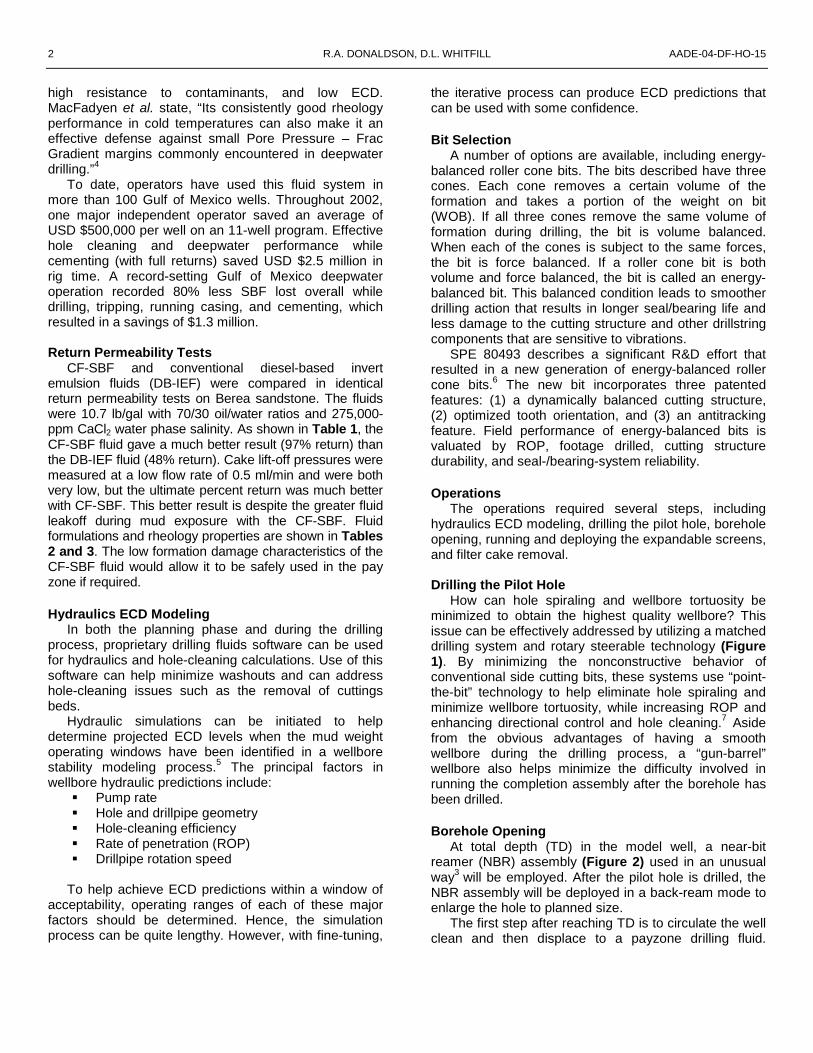
How can hole spiraling and wellbore tortuosity be minimized to obtain the highest quality wellbore? This issue can be effectively addressed by utilizing a matched drilling system and rotary steerable technology (Figure 1). By minimizing the nonconstructive behavior of conventional side cutting bits, these systems use “point-the-bit” technology to help eliminate hole spiraling and minimize wellbore tortuosity, while increasing ROP and enhancing directional control and hole cleaning.7 Aside from the obvious advantages of having a smooth wellbore during the drilling process, a “gun-barrel” wellbore also helps minimize the difficulty involved in running the completion assembly after the borehole has been drilled. Borehole Opening
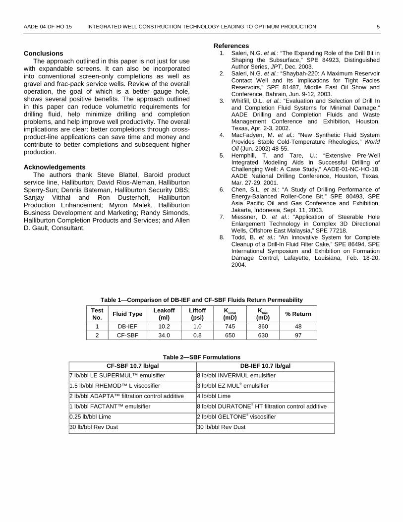
At total depth (TD) in the model well, a near-bit reamer (NBR) assembly (Figure 2) used in an unusual way3 will be employed. After the pilot hole is drilled, the NBR assembly will be deployed in a back-ream mode to enlarge the hole to planned size.
The first step after reaching TD is to circulate the well clean and then displace to a payzone drilling fluid.

AADE-04-DF-HO-15 INTEGRATED WELL CONSTRUCTION TECHNOLOGY LEADING TO OPTIMUM PRODUCTION 3
Several available industry system choices can be customized for such operations. For the model well, a polymer/salt system containing sized calcium carbonate bridging material was selected. Alternatively, magnesium oxide bridging material, which allows cleanup using ammonium salts rather than acids, may be used.8
After the well is displaced, the pullback under-reaming process with the NBR assembly commences. In this operation, only a small amount of the wellbore is typically removed to reach the desired borehole size to accommodate the expandable screen. Performing this unconventional pullback under-reaming operation has several benefits:
1. The filter cake produced is of the highest quality possible. Removing only a small amount of material from the well helps minimize the amount of drill solids that are incorporated into the mud system. These drill solids are circulated up the narrow pilot hole annulus rather than past the productive interval. This pattern of circulation in turn helps minimize the amount of drill solids in the filter cake. Drill solids can be a major damaging component of any filter cake.
2. During the pullback under-reaming process, any near-wellbore damage can be easily removed.
3. Another benefit of a pullback under-reaming operation is that any cuttings beds previously formed in the drilling phase can be removed. Removal is of critical importance. If the cuttings are left in place and the screen is expanded, sections of the screen may plug off, reduce the flow path, and impede production.
4. If any hole enlargement is generated during the drilling phase, its relative magnitude will be reduced during the pullback under-reaming process. The NBR assembly will enlarge the wellbore. Such enlargement, in essence, helps shorten the relative washout distance that may have been generated during the drilling phase.
5. One of the final benefits is the ease of deploying the expandable screen (Figure 3). Ease of deployment is due to a straight hole with good quality filter cake that provides needed lubricity. When the screen is in place, it is easily expanded. The high quality of the wellbore can allow more screen area to contact the well, enhancing compliance. Increased compliance can increase the life of the well from an equipment standpoint.
Once the well has been drilled, but before the
expandable screen is run and deployed, several fluid options should be considered:
• Circulate and condition the existing drilling fluid. This option will help reduce the particle-size distribution of the system, and any materials
removed that provided density can be replaced with fine calcium carbonate. The fluid is then conditioned such that it can flow through the completion assembly and not bridge off on its surface.
• Displace the open hole to a new system with particles sized so that they can pass through the completion assembly.
• Use an invert system, solids free, with heavy brine emulsified to provide required density.
• Use a drill-in fluid, solids free, with brine to provide density to help prevent any bridging of the completion assembly.
• Displace the well to a completion brine of required density.
If brines are used in the completion phase, it is
recommended that a number of factors be considered: • Compatibility of the brine with both the drilling
fluid and formation fluids • Crystallization point • Hydrate formation • Filtration of fluid to help prevent formation
damage from contaminating fines The completion fluid is typically the last fluid the
producing horizon will see and the last opportunity to remove any damage and help maximize well productivity, other than post-completion damage remediation. Expandable Screens
The expandable sand screen (ESS) used in the model well was developed to provide an answer to some of the industry’s more difficult completion problems. It has the capability to provide effective sand control combined with maximum internal flow area for slim-hole and/or large-ID completions. This significant step helps reduce the flow restrictions that are often introduced to the wellbore with a conventional sand-control completion.
ESS uses expandable tubular technology combined with premium sand-control screen technology. The screen material uses a plain Dutch weave (Figure 4) that is sintered to provide strength and durability. This filter layer has drainage layers on top and bottom to help improve the flow area by providing stand off, exposing more screen that can be accessed through the perforated shroud and base pipe.
The Dutch weave design allows the screen to be expanded without changing the filtration performance of the screen (Figure 5). This is accomplished by positioning the screen so that the weave wire is stretched during expansion, but the warp wires are not exposed to stress and therefore are not deformed. Because the warp wires determine the filtration

4 R.A. DONALDSON, D.L. WHITFILL AADE-04-DF-HO-15
capability of the screen, the screen can be expanded radially without changing the filtration capacity. As a result, ESS can provide the same filtration characteristics in both the unexpanded and expanded condition. If, for some reason, a portion of the screen is left unexpanded, filtration capability remains the same.
Fixed-cone expansion technology is used to expand the screen assembly. This same technology is used to expand casing. The expansion system is capable of expanding both screen and casing, which can allow solid pipe, annular barriers, to be installed over portions of the open hole that are nonproductive or are potentially damaging, such as exposed shale.
The expansion process is shown in Figure 6. The expansion requires two trips. The first trip is to run the screen and liner into the hole and set the liner. The second trip is to expand the screen.
The screen can be expanded either mechanically by setting weight on the expansion tool or hydraulically by using the hydraulic expansion tool. For long, horizontal intervals, the hydraulic expansion tool can allow the operator to continue expanding the screen even when getting sufficient weight on bottom to expand the screen mechanically is difficult. Even though the forces required to expand the ESS may be greater than other products in the industry, the hydraulic expansion system can provide a means to use ESS in long, horizontal sections.
The ESS system can bring a number of advantages. Some of these advantages are summarized as follows:
Provide the maximum ID completion for a given hole size.
The close proximity of the screen to the borehole face will help minimize any potential for annular flow between the screen and borehole face. Minimizing the potential for this flow helps stabilize the formation and minimize migration of formation fines.
The ability to expand solid pipe allows the isolation of shale sections that may be exposed in the open hole.
Expandable threaded connections help ensure system integrity both before and after expansion. The connections can also serve as annular barriers between screen joints.
Expansion can be performed mechanically using weight on the expansion cone, or hydraulically using the hydraulic expansion tool. The hydraulic tool can enable the screen to be expanded in longer horizontal sections where it may be difficult to apply sufficient weight for mechanical expansion.
The premium screen is welded, providing a continuous screen face that is strong, durable and very resistant to failure, even if it is deformed by extreme borehole changes during the life of the well.
The screen is a robust design that uses a
perforated base pipe instead of a slotted base pipe. As a result, ESS screens will not expand prematurely if weight is applied as the screens are run in the hole. Slotted pipes tend to expand if weight is applied, making placement of some of the competitive screens difficult in poor hole conditions or long, horizontal sections.
The perforated base pipe design can provide a mechanically strong screen that has good collapse resistance and will not easily deform in harsh production environments.
ESS can be run in and expanded in conditioned oil-based drill-in fluids. The ability to expand in this environment can provide a means of ensuring the best possible borehole quality and help minimize any problems associated with the presence of sensitive shale sections.
After expansion, the high-quality, constant diameter creates an environment where zonal isolation and water shutoff can be more easily executed. Using expandable casing inside the expanded screen to isolate problem sections resulting from water production is possible.
Case Histories
The first two installations of ESS (Table 4) were for a specialized cased-hole application in the Gulf of Mexico. Screens were expanded over two sets of perforations inside 7-in. casing, as part of a dual-zone completion.
The expandable screen allowed the operator to install the dual-completion equipment while minimizing the restriction imposed on the upper zone. Both installations were performed without any problem.
Installations 3 and 4 (Table 5) were openhole completions in 6.125-in. open hole. The ESS screens provided a maximum-ID sand-control completion in a slim-hole environment. In the 4th installation, blank pipe with annular barrier elastomer coating was used to isolate an exposed shale zone between two productive sands. Both of these screens were expanded with oil-based drilling fluid in the wellbore, helping maintain a stable, high-quality borehole. Filter-Cake Removal
After successfully running and expanding the screen, the filter cake can be cleaned before the well is placed on production. Filter cake can be removed in several ways. The easiest completion method is to simply flow the well back through the cake. Another option, which can provide more positive control on filter-cake removal, is using a time-delay breaker system. These breakers are used to provide a delay in the breaking action but will subsequently remove the polymers and calcium carbonate bridging particles by using combinations of acid and oxidizer sources that are produced in situ or delayed in activity.8
AADE-04-DF-HO-15 INTEGRATED WELL CONSTRUCTION TECHNOLOGY LEADING TO OPTIMUM PRODUCTION 5
Conclusions
The approach outlined in this paper is not just for use with expandable screens. It can also be incorporated into conventional screen-only completions as well as gravel and frac-pack service wells. Review of the overall operation, the goal of which is a better gauge hole, shows several positive benefits. The approach outlined in this paper can reduce volumetric requirements for drilling fluid, help minimize drilling and completion problems, and help improve well productivity. The overall implications are clear: better completions through cross-product-line applications can save time and money and contribute to better completions and subsequent higher production.
Acknowledgements
The authors thank Steve Blattel, Baroid product service line, Halliburton; David Rios-Aleman, Halliburton Sperry-Sun; Dennis Bateman, Halliburton Security DBS; Sanjay Vitthal and Ron Dusterhoft, Halliburton Production Enhancement; Myron Malek, Halliburton Business Development and Marketing; Randy Simonds, Halliburton Completion Products and Services; and Allen D. Gault, Consultant.
References 1. Saleri, N.G. et al.: “The Expanding Role of the Drill Bit in
Shaping the Subsurface,” SPE 84923, Distinguished Author Series, JPT, Dec. 2003.
2. Saleri, N.G. et al.: “Shaybah-220: A Maximum Reservoir Contact Well and Its Implications for Tight Facies Reservoirs,” SPE 81487, Middle East Oil Show and Conference, Bahrain, Jun. 9-12, 2003.
3. Whitfill, D.L. et al.: “Evaluation and Selection of Drill In and Completion Fluid Systems for Minimal Damage,” AADE Drilling and Completion Fluids and Waste Management Conference and Exhibition, Houston, Texas, Apr. 2-3, 2002.
4. MacFadyen, M. et al.: “New Synthetic Fluid System Provides Stable Cold-Temperature Rheologies,” World Oil (Jun. 2002) 48-55.
5. Hemphill, T. and Tare, U.: “Extensive Pre-Well Integrated Modeling Aids in Successful Drilling of Challenging Well: A Case Study,” AADE-01-NC-HO-18, AADE National Drilling Conference, Houston, Texas, Mar. 27-29, 2001.
6. Chen, S.L. et al.: “A Study of Drilling Performance of Energy-Balanced Roller-Cone Bit,” SPE 80493, SPE Asia Pacific Oil and Gas Conference and Exhibition, Jakarta, Indonesia, Sept. 11, 2003.
7. Miessner, D. et al.: “Application of Steerable Hole Enlargement Technology in Complex 3D Directional Wells, Offshore East Malaysia,” SPE 77218.
8. Todd, B. et al.: “An Innovative System for Complete Cleanup of a Drill-In Fluid Filter Cake,” SPE 86494, SPE International Symposium and Exhibition on Formation Damage Control, Lafayette, Louisiana, Feb. 18-20, 2004.
Table 1—Comparison of DB-IEF and CF-SBF Fluids Return Permeability
Test No.
Fluid Type Leakoff (ml)
Liftoff (psi)
Kinitial (mD)
Kfinal (mD)
% Return
1 DB-IEF 10.2 1.0 745 360 48
2 CF-SBF 34.0 0.8 650 630 97
Table 2—SBF Formulations CF-SBF 10.7 lb/gal DB-IEF 10.7 lb/gal
7 lb/bbl LE SUPERMUL™ emulsifier 8 lb/bbl INVERMUL emulsifier
1.5 lb/bbl RHEMOD™ L viscosifier 3 lb/bbl EZ MUL® emulsifier
2 lb/bbl ADAPTA™ filtration control additive 4 lb/bbl Lime
1 lb/bbl FACTANT™ emulsifier 8 lb/bbl DURATONE® HT filtration control additive
0.25 lb/bbl Lime 2 lb/bbl GELTONE® viscosifier
30 lb/bbl Rev Dust 30 lb/bbl Rev Dust

6 R.A. DONALDSON, D.L. WHITFILL AADE-04-DF-HO-15
Table 3—SBF Rheology Properties
Properties CF-SBF DB-IEF
Mud density (lb/gal) 10.7 10.7
Plastic viscosity (cP at 120°F) 27 23
Yield point (lb/100 ft2) 16 14
Gel strengths (10s/10m) — —
600 rpm reading 70 60
300 rpm reading 43 37
200 rpm reading 34 28
100 rpm reading 23 19
6 rpm reading 7 8
3 rpm reading 6 7
Electrical stability (volts) at 120°F 300 341
HPHT fluid loss (mL) at 250°F 2.2 3.1
Synthetic/Oil in S/W ratio 70 70
Water in S/W ratio 30 30
Pom 0.3 3.0
Lime (lb/bbl) 0.4 3.9
Cl whole mud 61,000 76,000
Ca whole mud 30,000 23,500
WPS (ppm) 274,000 273,725
WPS (mg/L) 339,760 339,419
Retort solids (%) 15 15
Retort water (%) 25.5 25.5
Retort synthetic/oil (%) 59.5 59.5
Corrected solids (%) 12.3 12.0
Avg. sp. gr. of sol 3.63 3.59
Low-gravity solids (%) 4.5 4.7
Low-gravity solids (lb/bbl) 41.7 44.0
High-gravity solids (%) 7.78 7.29
High-gravity solids (lb/gal) 114.4 107.2
Table 4—Specifications of First Two ESS Installations
Installation No.
Perf. Interval (ft)
Casing Screen Length (ft)
Screen (microns)
1 11,440 to 11,460 7-in., 29-lb/ft N-80
51 125
2 8,558 to 8,570 7-in., 29-lb/ft N-80 41 125
Table 5—Specifications of Two ESS Completions in 6.125-in. Open Hole
Installation No. Angle
Depth (ft)
Screen Length (ft)
Screen (micron)
3 37 3,400 92 250
4 90 6,400 286 250
AADE-04-DF-HO-15 INTEGRATED WELL CONSTRUCTION TECHNOLOGY LEADING TO OPTIMUM PRODUCTION 7
Figure 1—Matched drilling system combines a specially designed pin-down positive displacement motor and an extended-gauge box-up bit.
Figure 2—Near-bit reamer cutaway (left) and rigsite deployment (right).
DN
0044
68
DN
0044
69

8 R.A. DONALDSON, D.L. WHITFILL AADE-04-DF-HO-15
Figure 3—Expandable screen.
Figure 4—Expandable screen details.
DN
0044
70
DN
0044
71

AADE-04-DF-HO-15 INTEGRATED WELL CONSTRUCTION TECHNOLOGY LEADING TO OPTIMUM PRODUCTION 9
Figure 5—Dutch weave expansion capabilities.
Figure 6—The expansion process.
DN
0044
73
DN
0044
72