aae 241: spacecraft design proposal professor: k. sivier · pdf fileaae 241: spacecraft design...
TRANSCRIPT

,',
;
N91-16048 12ft
Project Cerberus: (1 Flyby Mission to Pluto
AAE 241: Spacecraft Design Proposal
Professor: K. Sivier
Section Teaching Assistant: A. Koepke
University of Illinois at Urbana-Champaign
NASA Advanced Design Program
Spring Semester 1990
{:-- ...;
I I \
https://ntrs.nasa.gov/search.jsp?R=19910006735 2018-04-17T12:33:59+00:00Z

"-,..-
J~-,~ '41 '1l1"'?4 Theodore W. Humphrey, Project Leader Attitude, Articulation, & Control
~l:!$:~/Y~ ~ i:~ Mission Management, Planning, & Costing
Bruce E. Hackett
Science
2~j ;(I&~ Ral~h G. Kennedy Propulsion
Structures 2_
i!!:i~ Command, Control, & Communication

Section
INTRODUCTION
Section 1-1:
Section 1-2:
Section 1-3:
Section 1-4:
Section 1-5:
References
Appendix
Appendix
S.e.c.tiaa__
Section 2-1:
Section 2-2:
Section 2-3:
Section 2-4:
Section 2-5:
Section 2-6:
A-l:
A-2:
References:
Appendix B-I:
Appendix B-2:
Section _;
Section 3-1:
Section 3-2:
Section 3-3:
Section 3-4:
Section 3-5:
References
Appendix C:
Title
TABLE OF CONTENTS
MISSION MANAGEMENT, PLANNING, &
MMPC REQUIREMENTS
SELECTION OF MISSION TYPE
TRAJECTORY DETERMINATION
MMPC EFFECTS ON OTHER SUBSYSTEMS
COSTING
COSTING (MMPC)
ACRONYMS
EQUATIONS AND CONVERSION FACTORS
STRUCTURES
LISTING OF REQUIREMENTS
MAJOR DESIGN FEATURES
LAYOUT OF COMPONENTS/INERTIA PROPERTIES
MATERIAL SELECTION
THERMAL CONSIDERATIONS
LAUNCH VEHICLE COMPATIBILITY AND ON-ORBIT
ASSEMBLY
NUMBERED
OTHER
ITERATIONS OF THE SPACECRAFT CONFIGURATION
MINIMIZATION OF TRUSS MASS
POWER AND PROPULSION
INTRODUCTION
POWER
PROPULSION MODULE
ELV/UPPERSTAGE TRANSFER VEHICLE
CONCLUSION
EQUATIONS
1
3
3
4
11
12
16
16
17
18
19
25
28
31
33
35
35
36
37
39
40
45
51
52
53
54

_ection 4:
Section 4-1:
Section 4-2:
Section 4-3:
Section 4-4:
Section 4-5:
Section 4-6:
References
Appendix D
S.ey..fiaL.
Section 5-1:
Section 5-2:
Section 5-2.1:
Section 5-2.2:
Section 5-2.3:
Section 5-3:
Section 5-3.1:
Section 5-3.2:
Section 5-3.3:
Section 5-4:
References
Appendix E-1
Section 6:
Section 6-1:
Section 6-2:
Section 6-3:
Section 6-4:
Section 6-5:
Section 6-6:
Section 6-7:
References:
ATTITUDE, ARTICULATION, AND CONTROL (AACS)
INTRODUCTION
MAJOR FEATURES OF THE AACS
HARDWARE SELECTION AND PLACEMENT
SCANNING AND POINTING REQUIREMENTS
IMPLEMENTATION
ATTITUDE CONTROL MODES
CONCLUSION
COMMAND, CONTROL AND COMMUNICATION
INTRODUCTION
COMMAND AND CONTROL
COMPUTER COMMAND SUBSYSTEM
ATTITUDE AND ARTICULATION CONTROL SUBSYSTEM
FLIGHT DATA SUBSYSTEM
COMMUNICATIONS
TELEMETRY
RADIO FREQUENCY SUBSYSTEM
SPECIFICATIONS
CONCLUSION
SCIENCE SUBSYSTEM
RFP REQUIREMENTS
METHOD OF ATTACK
SCIENCE OBJECTIVES
COMPONENTS
SCIENCE TIMELINE
INTERACTION WITH OTHER SUBSYSTEMS
FUTURE CONCERNS
NUMBERED
OTHER
IMPLEMENTATION PLAN
56
57
62
66
66
67
68
69
70
70
72
73
73
73
74
75
76
77
79
81
83
84
85
86
91
93
94
95
95
96
ii

INTRODUCTION
Pluto, the ninth planet in the solar system, is named after the Greek god
of the Underworld. The namesake of this project is Cerberus, Pluto's watchdog
which faithfully stood guard at the gates of Hades.
[ •
Cerberus is designed to meet the requirements stated in the Request for
Proposal (RFP). Those requirements that apply to all subsystems are
summarized below:
1)
2)
3)
4)
5)
6)
7)
8)
9)
Develop a conceptual design for an unmanned spacecraft to study
Plutonian space.
Optimize performance, weight and cost.
Spacecraft should be simple, reliable and easy to operate.
Use off-the-shelf hardware and technology available by 1999.
Identify and minimize on-orbit assembly.
Should be able to perform several possible missions.
Sufficient design lifetime to carry out its mission plus a reasonable
safety margin.
Use latest advances in Artificial Intelligence.
For costing and overall planning, assume that four spacecraft will be
built.
The goal of the Cerberus Project is to design a feasible and cost-effective
mission. The design stresses proven technology that will avoid "show
stoppers," which could halt mission progress. Cerberus also utilizes the latest
advances in the spacecraft industry to meet the stringent demands of a

journey to the edge of the solar system.
means to unlocking the mysteries of Pluto.
The result is Cerberus, a practical

r
Section 1-1:
Section 1: MISSION MANAGEMENT. PLANNING.
& COSTING (MMPC)
MMPC REOUIREMENTS
MMPC entails several requirements from the Request For Proposal (RFP)
specific to the subsystem. These are in addition to general requirements
which pertain to the mission as a whole. The MMPC requirements, specific and
derived, are listed below.
1)
2)
3)
4)
5)
6)
7)
8)
9)
10)
Spacecraft must travel to Plutonian space.
Spacecraft must travel to Plutonian space via an optimal
trajectory.
a.
b.
Trajectory should be optimized for Av.
Trajectory should be optimized for time
of flight (TOF).
Individual bums must remain within limits of
propulsion system.
Spacecraft trajectory should not subject spacecraft to
conditions which will cause it undue damage.
MMPC analyst must perform cost estimates of individual
subsystems.
MMPC analyst must perform cost estimate of entire
mission.
Mission type must be one of three types:
flyby, orbiter, or lander.
MMPC analyst must outline mission sequence of events.
Launch should take place sometime between 2000 2010 A.D.
Acronyms for Section 1; MMPC are listed in Appendix A-1.
Section 1-2: SELECTION OF MISSION TYPE
The flyby type of mission has been determined to be the best for the
Cerberus project. This decision was based upon the results of preliminary
trajectory studies using the multiple impulse optimizing program, MULIMP, as
well as other considerations. These considerations include:

1)
2)
3)
4)
Section 1-3:
Existing technology does not facilitate the
transportation of fuel mass necessary to burn into
orbit capture at Pluto. This precludes the orbiter and
lander class missions. MULIMP studies produced Av values which
would be required for orbit capture. There exists no trajectory
which would allow orbit capture at Pluto, given the available
technology, and the acceptable TOF for this mission.
Pluto and Charon are only separated by 19400 km.[3] An object
placed in orbit about Pluto would likely have its orbit perturbed
such that it left Plutonian space.
Other general solar system science can be emphasized
on a flyby mission. Examples are a Jupiter study
before arrival at Plutonian space, and a measurement
of the heliopause after Pluto passage.
This is a preliminary mission; it is prudent for this to
be of the flyby class given present knowledge of
Plutonian space. This mission will assist in
determining the benefit of another Pluto mission. This
venture will yield information required for launch of
an orbiter or lander Class mission, when technology for
such a mission becomes available. It is also prudent to
keep this mission at the flyby class to keep from
overshadowing the Lunar and Mars initiatives.
TRA.IECTORY DETERMINATION
Several paths were studied as a possible route to Pluto.
included different gravity assist flyby trajectories:
1)
2)
3)
4)
5)
Earth Pluto
Earth Jupiter- Pluto
Earth - Mars - Jupiter- Pluto
Earth - Venus - Earth - Earth - Jupiter - Pluto
Earth - Earth - Jupiter - Pluto
These paths
4

i
Certain data were required to facilitate logical study of trajectories withMULIMP. Values of ,_v and TOF required for Hohmann transfer between the
various planets of interest were calculated by hand. These are listed in Table
1-1. Equations and parameters used in these calculations are listed in
Appendix A-2.
Table 1-1: Hohmann Transfer Values
Planets of Interest
i
Earth & Pluto
Earth & Mars
Earth & Jupiter
Av_km/s}
11.8120
2.9458
8.7920
TOF(days)
16581.5465
258.9324
997.5984
Mars & Jupiter 5.8968 1125.6354
The orbit periods and synodic periods of the planets of interest are
given in Table 1-2.[2]
Table 1-2: Orbit Periods and Synodic Periods
Planet
Venus
Mars
Jupiter
Pluto
Orbit Period
224 days
687 days
11.9 years
247 years
Synodic
Period_da],s_
584
778
398
367
The first path to be investigated was a direct transfer from Earth to
Pluto. Observation of hand calculated data and study of available literature[3]
lead to the following conclusions:
1) The mission TOF would be too long for practical
purposes using existing technology.

2)
3)
The zXv at Earth parking orbit (1.0437 Earth radii)
would be too large for available propulsion systems.
The launch energy (C3) would be in excess of the
capabilities of existing launch vehicles.
The second path to be investigated was a transfer to Pluto with a gravity
assist at Jupiter. The first step in studying this trajectory was to use MULIMP
to find the optimal transfer from Earth to Jupiter, in terms of zXv, in the early
part of the first decade of the twenty-first century. Knowing this locally
optimal launch date, MULIMP optimized the trajectory to its completion at
Pluto. The first launch date was then incremented by an amount equal to
Jupiter's synodic period, and the Earth - Jupiter - Pluto transfer was again
optimized by MULIMP, This process was repeated until the incremented
launch date fell outside the ten year launch window prescribed by the RFP.
MULIMP data also displayed position of each event in three dimensional
Cartesian coordinates, with the sun as origin and its ecliptic as the X-Y plane.
With this data, a path could be graphically plotted to ensure smooth flow of the
trajectory in a counter-clockwise manner.
Upon examining the various data output by MULIMP, it was clear that
although the Earth Jupiter - Pluto trajectory was an improvement upon the
Earth Pluto trajectory, it was still unsatisfactory for these reasons:
1)
2)
3)
The TOF was generally greater than 18 years.
The z_v at Earth parking orbit was larger than desired
for cost effectiveness of the mission.
The launch energy approached or exceeded
unacceptable levels (i.e., from 90 to several thousand).
The next path under consideration was Earth - Mars Jupiter Pluto. This
trajectory was studied employing a similar method of attack to that used for the
Earth Jupiter Pluto study. The best early launch date to Mars was
determined using MULIMP, and this launch date was incremented by Mars'
synodic period through 2010. At each launch date, MULIMP optimized the
complete Earth - Mars - Jupiter - Pluto transfer. Several MULIMP studies were
also performed in the region of time of two months preceding and following

each of the aforementioned launch dates. Once again, this trajectory displayedimprovement over the previous path studied, particularly in these areas:
1)
2)
3)
Launch energy: C3 fell generally in range of 10 - 15.
Av from Earth parking orbit was reduced to the range
of 3 to 4 krn/s
TOF was in the range of 15_+2 years.
i
Prohibiting problems with this flyby path arose at Mars, where an
impulse of at least 6.3 km/s was required.
The ensuing path under scrutiny was an extension of Galileo's Venus
Earth - Earth Gravity Assist (VEEGA) trajectory.J4] A flyby of Jupiter was added
before the spacecraft continued on to Pluto. It became apparent upon
reviewing MULIMP test output that the planets of the solar system are not in
position conducive to this type of transfer during the prescribed ten year
launch window. Although TOF was reduced significantly to roughly six years,
flyby impulses unattainable.
The final trajectory to be considered was an Earth- Earth Jupiter -
Pluto path. The method of attack for studying this path was again similar to
that described previously. This trajectory yielded the most satisfactory values.
Table 1-3 displays values from each type of trajectory studied. These values
were compared in a trade study manner to determine the best course of flight.
Although these values are not likely to be the absolute optimum value for each
case, they were determined to be sufficiently representative.
Table 1-3: Characteristic MULIMP Values for Different Trajectories
i
EP
Path
EJP(typical)
EJP(unusual)
Av(km/s)
N/A
11.195
8.194
TOF(_ears)
N/A
26.935
15.383
C3
N/A
94.560
90.523
Comments
Excluded from
MULIMP study
Path falls through
Jupiter at .8 planet
radii

EMJP(typ.)
EMJP(unus.)
EVEEJP
EEJP
E: Earth
10.915
3.788
93.556
5.941
13.665
14.727
6.072
18.688
J: Jupiter M: Mars P: Pluto
11.376
10.814
13.687
47.518
V: Venus
AV at Mars: 7.201
km/s.
Unattainable.
Path falls through
center of Mars & .723
Jupiter radii.
Combined Av for the
two E flyby's: 89.733
km/s.
The Earth
considerations:
Earth - Jupiter - Pluto trajectory was selected due to several
1)
2)
3)
4)
5)
6)
The Av from Earth parking orbit was determined to be
attainable for Cerberus' mass (see Section 3:
Propulsion).
The launch energy was determined to be attainable for
this mission using existing technology (see Section 3:
Propulsion).
Midcourse and flyby hv's were determined to be
feasible(see Section 3: Propulsion).
Flyby of Jupiter occurs at a distance which does not
require addition of radiation shielding to Cerberus'
structure.
There is a launch window of eleven days.
Launch occurs early enough in the 2000 - 2010 period
to allow postponement and still make that ten year
window.
A later launch date would allow for more development time, better
weather for launch, and a chance to find a better trajectory. However, Pluto is
moving away from its perihelion distance of 29.6 AU, which it reached in 1989.

Therefore, an earlier launch has the potential to travel less distance toPlutonian space.
Table 1-4 displays information on Cerberus' trajectory, and outlines themission sequenceof events. The launch date shown falls in the middle of theeleven day launch window.
Date
2002 Jan4
Table 1-4: Cerberus' Traiect)rl¢ & Sequence of Events
Av Radius of Passage
Ikm/st
5.195
2003 Jun 11 0.418
2004 Nov 25
2005 Jan 23
2006 May27
2006 Jun 21
2020 Aug 18
Event
Depart Earth parking
orbit
Midcourse burn
Earth flyby
Midcourse burn, Plane
change
Begin Jovian science (50
days)
Jupiter flyby:
closest approach
Begin Plutonian science
(50 days)
Pluto flyby:
closest approach
2020 Sep 12
0.008
0.320
0.000
1.0437 planet radii
1.3000 planet radii
26.780 planet radii
The redeeming values of this course were considered advantageous
enough to outweigh the disadvantage of the long TOF. The long time is a
disadvantage since the spacecraft, its instruments, and components have not
been tested and proven for such a length of time.
Figure 1-1 graphically displays A v versus launch date in 30 day
intervals for a span of 420 days surrounding the launch date. Figure 1.2
graphically displays A v versus launch date in one day increments for a span
of two weeks surrounding the launch date.
9

60
5O
43
E 33
> 23
1 I I I
0 103 200 300 403
Launch date + 2452000 (Julian Days)
Figure 1-1" Comparison of Delta v versus
Launch Date over 420 days
!
5(30
12
11
E 10
> 9"
6
" I " I ' I " I " I " | " I " I " I " I
70 72 74 76 78 80 82 84 86 88 gO
Launch Date + 2452200 (Julian Days)
Figure 1-2: Comparison of Delta v versus
Launch Date over 2 weeks
10

Section 1-4: MMPC EFFECTS ON OTHER SUBSYSTEMS
r-
i
MMPC decisions naturally affect the other subsystems involved in the
Cerberus mission, as all of these subsystems are integrated to accomplish one
task.
The science analyst's decisions are influenced by the trajectory.
Cerberus' course of flight determines which objects in space are available for
study. Decisions are further affected by the specific proximity of the
spacecraft to the aforementioned objects during flight, as experiments can be
affected by closeness or distance to the object of scrutiny. The science analyst
must determine from the trajectory the window of time available for study. In
Cerberus' case, there are fifty days allotted for study at Pluto.
TOF is a concern of all functional subsystems: science, propulsion,
attitude articulation & control, communication, and structures. If TOF exceeds
the known service lifetime of a given unit, there may be concern for the
ability of the unit to accomplish its ultimate task.
Closeness of passage to radiating bodies such as our sun and Jupiter is a
structural concern. If flyby is too close to a radiating body, extra shielding
must be added to the craft to protect it from undue damage. In Cerberus' case,
the trajectory does not carry it close enough to the sun to merit unusual
concern. Cerberus' path also falls far beyond the 'very safe' distance of ten
planet radii when flying by Jupiter. The structure must also support the fuel
mass determined by the _v required.
The communication analyst must know when the craft will be in
occultation behind a body. This knowledge is required in order to prepare
autonomous control during this period without contact with the spacecraft.
The propulsion analyst must make decisions for that subsystem based
upon data furnished by MMPC. Launch vehicle and propulsion system
selection must reflect the needs stated for the trajectory. The spacecraft must
carry with it the capability to perform midcourse burns when necessary.
11
Section 1-5: COSTING
i
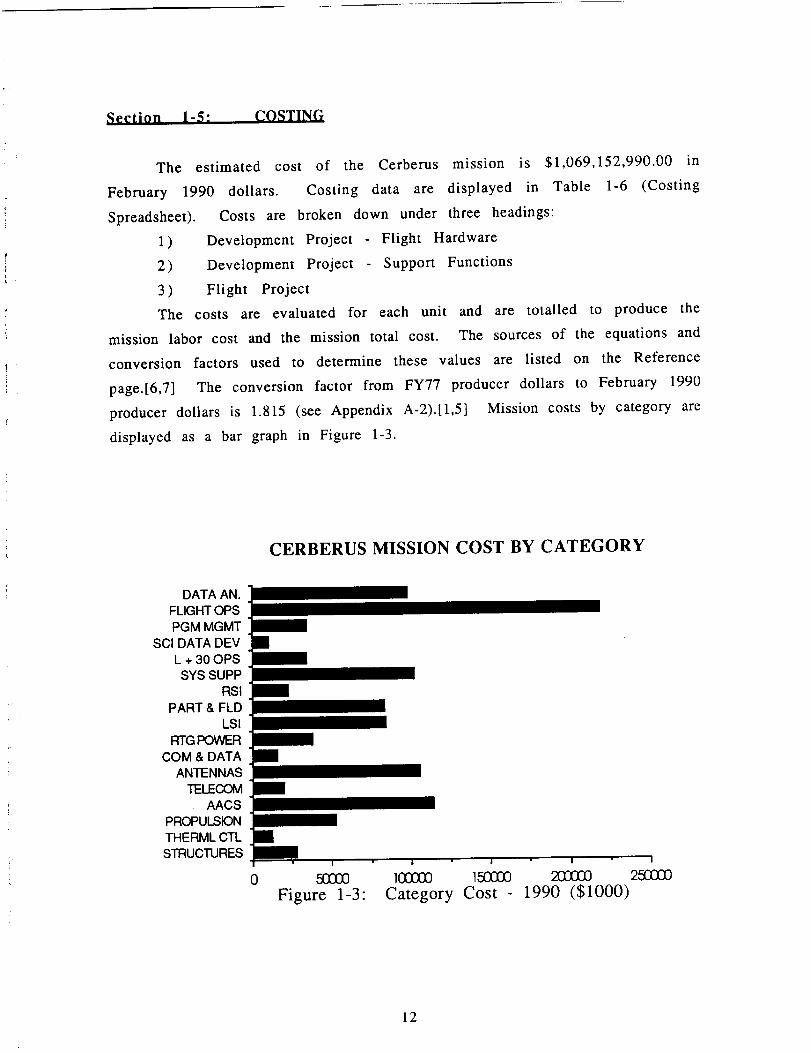
The estimated cost of the Cerberus mission is $1,069,152,990.00 in
February 1990 dollars. Costing data are displayed in Table 1-6 (Costing
Spreadsheet). Costs are broken down under three headings:
1) Development Project Flight Hardware
2) Development Project - Support Functions
3 ) Flight Project
The costs are evaluated for each unit and are totalled to produce the
mission labor cost and the mission total cost. The sources of the equations and
conversion factors used to determine these values are listed on the Reference
page.[6,7] The conversion factor from FY77 producer dollars to February 1990
producer dollars is 1.815 (see Appendix A-2).[1,5] Mission costs by category are
displayed as a bar graph in Figure 1-3.
CERBERUS MISSION COST BY CATEGORY
DATA AN.FLIGHT OPSPGM MGMT
SCI DATA DEVL + 30 OPSSYS SUPP
RSIPART & FLD
LSIRTGPOV__R
COM & DATAANTENNAS
TELECOMAACS
PROPULSIONTHERML CTLSTRUCTURES
I
/
/
[]I
I I I I I
0 5(_0 1(33333 1,5(3E_ 202£_ 2513300Figure 1-3: Category Cost - 1990 ($1000)
12

r
Number of Spacecraft: 4
DEVELOPMENT PROJECT - FLIGHT HARDWARE
FLIGHT HARDWARE TOTAL COST: $572892850.01
STRUCTURES AND DEVICESMASS (kg) 168.00 ADJUSTED
DLH 419.99 262.49RLH 178.15 178.15
SYSTEM SUBTOTAL: 440.64
THERMAL CONTROL, CABLING, AND PYROTECHNICSMASS (kg) 82.00 ADJUSTED
DLH 276.86 69.22RLH 126.47 126.47
SYSTEM SUBTOTAL: 195.68
PROPULSIONMASS (kg) 90.00 ADJUSTED
DLH 596.57 551.82RLH 201.13 201.13
SYSTEM SUBTOTAL: 752.96
ATTITUDE ARTICULATION AND CONTROL
MASS (kg) 85.00 ADJUSTEDDLH 1202.55 1112.36RLH 656.88 656.88
SYSTEM SUBTOTAL: 1769.24
TELECOMMUNICATIONMASS (kg) 10.00 ADJUSTED
DLH 189.44 189.44RLH 130.37 130.37
SYSTEM SUBTOTAL: 319.80
ANTENNASMASS (kg) 40.00 ADJUSTED
DLH 1147.07 1147.07RLH 534.24 534.24
SYSTEM SUBTOTAL: 1681.31
COMMAND AND DATA HANDLINGMASS (kg) 15.00 ADJUSTED
DLH 186.03 186.03RLH 90.33 90.33
SYSTEM SUBTOTAL: 276.37
Table 1-6: Cerberus Mission Costing Spreadsheet Values (page 1 of 3)Note: Labor Hours listed in 1000's of hours
Dollar amounts given in February 1990 producer dollars
13

l
MITG POWERMASS (kg) 50.00 ADJUSTED
DLH 547.61 342.26RLH 348.15 348.15
SYSTEM SUBTOTAL: 690.40
LINE SCAN IMAGING
MASS (kg) 29.70 ADJUSTEDDLH 761.60 761.60RLH 450.03 450.03
SYSTEM SUBTOTAL: 1211.64
PARTICLE AND FIELD INSTRUMENTS
MASS (kg) 28.00 ADJUSTEDDLH 692.84 692.84RLH 577.58 577.58
SYSTEM SUBTOTAL: 1270.42
REMOTE SENSING INSTRUMENTSMASS (kg) 27.00 ADJUSTED
DLH 305.49 305.49RLH 40.20 40.20
SYSTEM SUBTOTAL: 345.69
TOTAL HARDWARE ADJUSTED DLHTOTAL HARDWARE ADJUSTED DLH + RLH
5620.618954.15
DEVELOPMENT PROJECT - SUPPORT FUNCTIONS
SUPPORT FUNCTIONS TOTAL COST: $180416000.00
SYSTEM SUPPORT AND GROUND EQUIP.DLH 1732.94
LAUNCH + 30 DAYS OPERATIONS AND GROUND SOFTWARE
DLH 551.27
SCIENCE DATA DEVELOPMENTDLH 108.25
PROGRAM MANANGEMENT/MA&EDLH 601.40
Table 1-6: Cerberus Mission Costing Spreadsheet Values (page 2 of 3)Note: Labor Hours listed in 1000's of hours
Dollar amounts given in February 1990 producer dollars
14

l
I
FLIGHT PROJECT
FLIGHT PROJECT TOTAL COST:
FLIGHT OPERATIONSDLH 3544.50
DATA ANALYSISDLH 1506.41
$180416000.00
TOTAL MISSION DLHTOTAL MISSION DLH + RLH
MISSION TOTAL COST:
13665.3916998.93
$1069152990.01
Table 1-6: Cerberus Mission Costing Spreadsheet Values (page 3 of 3)Note: Labor Hours listed in 1000's of hours
Dollar amounts given in February 1990 producer dollars
15

r •
i
.
.
3.
o
°
.
.
References
Carson, C. S. (editor in chief), Survey Qf C_rren_ Business, Volume 70,
Number 2, February 1990
Conway, B. & Prussing, J., Orbital Mechanics, 1989, p. 127
Croswell, K., Pluto: Enigma on the Edge of the Solar System,Astronomy, July, 1986
D'Amario, et al., Galileo, 1989 VEEGA Mission Description: Paper AAS89-431, JPL AA$/AIAA Astrodynamics Specialist C_)nfcren_e, Stowe,
VT, August 7-10, 1989
Kincannon, C. L., et al., Statistical Abstract of the United States,109th
Edition, United States Bureau of the Census, Washington, D. C., 1989
Kitchen, L. D., Manpower Cost Estimation Model for Automated
Planetary_ Projects - 2, Report No. SAI 1-120-399-C2, Science
Applications, Inc., September, 1973
Pekar, P. et al., Manpower Cost Estimation Model for AutomatedPlanetary Projects, Science Applications, Inc., September, 1973
Appendix A-l; Acronyms
AU
AvDLH
kmLMMPCMULIMPRFP
S
TOFVEEGA
Astronomical Unit (149.6E6 km)change in velocity (km/s)Direct Labor HourskilometerLaunch
Mission Management, Planning, and CostingMultiple Impulse Optimizing ProgramRequest for Proposalsecond
Time of Flight
Venus - Earth - Earth Gravity Assist
16

Aanendix A-2: Eouations and Conversion Factors
Hohmann Transfer
rVenus = .723 AU
rEarth = 1 AU
rMars = 1.52 AU
rJupiter = 5.203 AU
rpluto(average) = 39.4 AU
rpluto(perihelion) = 29.6 AU
IXSun = 1.327Ell km3/s 2
R=r2/rl
AVl/Vcl = (2R/(I+R)) "5 - 1
VCl = (_Sun/rl) "5
Av2/Vcl = R (-'5) (2/(R(I+R))) "5
a = (rl + r2)/2
tHohmann = _(a3/p.Sun) •5
Costing
Purchasing Power of Dollar
FY77 1982/1984 February 1990
Consumer 1.649
Producer 1.546
Consumer Dollar Conversion Factor:
Producer Dollar Conversion Factor:
1.00
1.00
2.1088
1.8150
.782
.852

Section 2: STRUCTURE_
Section 2-1: LISTING OF REOUIREMENTS
Easily the most difficult part of designing any spacecraft is dealing with
the vague, and often contradictory, requirements of the mission.
Requirements such as the ones listed in the Request for Proposal (RFP)
identify the objectives of the design, and it is up to the analyst to achieve the
optimum solution. Listed at the beginning of this proposal are the
requirements that must be met by all subsystems. Concepts such as
minimizing cost, keeping the design simple and reliable, etc., must be on the
mind of the analyst at all times. The most important part of preliminary
design is meeting as many, if not all, of the requirements outlined by the RFP.
As well as meeting the overall objectives of the mission, each subsystem
must also satisfy many derived requirements. These derived requirements are
based on the objectives outlined in the RFP, but they are specific to the
subsystem.
For the Structures Subsystem, the derived requirements have a great
deal to do with the overall design of the spacecraft (spacecraft). Below is a
listing of the derived requirements for the Structures Subsystem. All of them
are objectives specific to this subsystem, but they are based on conceptsoutlined in the RFP.
1)
2)
3)
4)
5)
6)
7)
8)
9)
Overall design of the Cerberus spacecraft
Design to maximize science performance
Calculation of inertia properties of spacecraft
Material selection for the various components
Thermal control considerations
Verification of Launch Vehicle Compatibility
Identification of any On-Orbit Assembly (OnOA)
Structural analysis of truss bays to meet launch conditions
Identification of subsystem interaction
The RFP requirements kept in mind when designing the spacecraft as
well as the overall mission plan agreed on by the group. In essence, Cerberus
is meant to be a conservative project. With the Moon/Mars initiative the
18

f :
i
centerpiece of both NASA's and Congress' space commitment, it was believed
that this was the best approach. Nothing was to be done that would
overshadow these important advances. From the beginning, Cerberus was
meant to be an inexpensive mission. This meant that as much off-the-shelf
hardware should be used. Fortunately, with the Mariner Mark II (MMII)
program just beginning, it was believed that a good amount of off-the-shelf
hardware would be available.
This conservative, off-the-shelf approach is well reflected by the
structural design methodology. Older missions such as Voyager and Galileo
were studied to understand what problems they had and the solutions to those
problems. The more recent MMII program gave valuable insight into new
methods of spacecraft design. The most important part of studying these
previous missions was understanding how the mission to Pluto differed. With a
mission lifetime of 18.7 years, and a safety margin of approximately 5 years, it
is easy to see the major differences between the projects. Only Voyager has
come close to having a mission lifetime of this magnitude. The conservative
basis of Cerberus is well-suited to meeting this difficult requirement. Material
selection, spacecraft configuration, and thermal design all reflect this overall
mission plan.
The most important requirement for the structural designer was
ensuring Cerberus ability to carry out its mission. The objective of a Pluto
probe is to gather as much scientific data as possible, in the most efficient and
cost-effective way. This must be kept in mind at all times when designing the
spacecraft. It is believed that this design, with its conservative and off-the-
shelf approach, is the most effective and cost-efficient way to successfully
complete the long journey to Pluto.
Section 2-2: MA.IOR DESIGN FEATURES
The most important part of the Structures subsystem is determining the
overall layout of Cerberus. There is a great deal of system interaction that
occurs for an effective design. Not only must the requirements of the RFP be
satisfied, but any constraints imposed by the different subsystems must be
taken into consideration.
Figure 2-1 represents a view of Cerberus from the bottom of the
spacecraft (see next page). Some of the major design features are visible from
19

(_CM of spacecraft
4.8m meter
Hydrazine
Bladder (I of 2)
Th!uster(I of 4)
MITG (2)
i0 Bay Bus
(i.5m wide)
Scale: 1/25
4cm = I m
Figure 2-I Bottom view of
CerberusZU
High Accuracy
Science Platform
Antenna
Heliu
Tank
(i of 2)
Mag
Cannister
When dep
om wil
I
Ted,
_xtend
Low Accuracy
Science Platform

r'-
,f :
k
this angle. A 10 bay bus is the major structural component of the spacecraft.
It contains the electronics that control the mission to Pluto. The following is a
list of the major design features, grouped by subsystem.
Table 1-1"
Science
CCC
Summary of major design features
Cerberus contains two science platforms, 1 for
High Accuracy science (HAP), the other for
Low Accuracy science (LAP). Both platforms
have a good field of view, maximizing the
science performance of the instruments.
The HAP is protected by a radiation shield. This
will minimize the effects of the space
environment by protecting the instruments
from both radiation and micrometeroid impact.
The MITGs have been placed opposite the
magnetometer to eliminate interference.
14.5 m separates the two components.
Over
A dipole antenna has been placed on Cerberus
for radio science. The two antennas were
placed at a ,90 angle to each other to satisfy
science requirements.
A 4.8 m High Gain Antenna (HGA) is the
component that is responsible for telemetry. It
has been placed on top of the 10 bay bus. It can
be folded for launch.
21

Power &
Propulsion
Attitude,
Articul-
ation and
Control
Mission
Manage-
ment and
Planning
Two MITGs are the main power source for
Cerberus. They have been placed on a boom .8
m away from the bus.
A propulsion module that will provide
necessary Av's for the spacecraft is attached at
the bottom of the bus. It's consists of 2 bladders,
2 tanks and a support structure. Two large
bladders (r=.335 m) are for the Hydrazine
propellant, two small aluminum tanks (r=.ll0
m) contain the Helium pressurant. A plate
made of titanium is the material for the support
structure.
There are 4 sets of thrusters that control the
attitude of the Cerberus spacecraft. They are
placed along the principal axes of the craft•
• A star tracker and sun sensor have been placed
on the HAP for inertial reference.
• The dimensions of the spacecraft have been
sized to conform to the launch vehicle•
Since the scientific instruments will be fully operational during the
whole flight, there is nothing in the design that precludes it from performing
several possible missions.
The overall design approach reflects the conservative nature of the
mission. Most of the equipment is off-the-shelf hardware, with inheritance
from both Galileo and the more recent MMII program• Cerberus is simpler
than Galileo, with no spun sections, and only one bus. Most of the structural
design reflects the newer MMII program [1]. The 10 bay bus was chosen to
take advantage of any extras from this program, since the Comet Rendezvous
and Asteroid Flyby (CRAF) uses this configuration. The two scan platforms also
22

reflect the CRAF inheritance, as does the short MITG boom and the long (12m)magnetometer truss structure. All of these design features representcompliance with the requirement to maximize use of off-the-shelf hardware.
Figure 2-2 representsa side view of the Cerberusspacecraft. Thisangle shows two features that differ from the CRAF configuration. The first isthe Galileo type antenna (4.8m diameter) that will provide telemetry for themission. Again, even this feature is inherited from the Galileo project, so itdoes not represent a major redesign. The propulsion module also represents achange from MMII. It is smaller, fitting inside the 1.5m space inside the bus.Although different from MMII, it is not much different than modules used forother interplanetary missions.
As mentioned before, the 10 bay bus contains the electronics that willcontrol the mission to Pluto. Each bay contains electronics for one subsystem,although each subsystem was assigned more than one bay. Figure 2-3 is agraphical representation of each of the bay assignments.
7 9 ")
Figure 2-3: Electronics contained in each bay
The bay assignmentswere selected to minimize cabling and also to evenout the inertia properties of the electronics stored in the bus.
23

Section 2-3: LAYOUT OF COMPONENTS/INERTIA PROPERTIES
Now that the major design features of the Cerberus have been discussed,
the exact layout of the components and the inertia properties will be studied.
The location of the components is directly related to the inertia
properties of the spacecraft. In turn, the problem of attitude control is
heavily dependent on the inertia properties. To make the attitude control
problem as simple as possible, there were certain objectives of the design.
These objectives are listed below.
1) The center of mass of the whole structure should be kept near the
middle of the bus. A good location was selected at (0,0,-.40).
2) The off-diagonal terms of the inertia tensor should be kept at a
minimum. This means that the principal directions of the
spacecraft lie along the directions chosen for the initial layout (See
Figures 2-1 and 2-2 for these axes).
An initial configuration for Cerberus was drawn up. In the
preliminary phase, close attention was paid to the symmetry of the spacecraft.
The two science platforms were placed on opposite ends of the bus since it was
believed that their inertia properties would even out. The magnetometer and
the RTGs were then placed at 90" angles to these platforms. Constraints
imposed on the design were kept in mind at all times. Most importantly, the
RTGs were kept far from the magnetometer, and the HAP and the LAP were
given a good field of view. The size of the propulsion module enabled it to be
placed inside the 1.5m wide electronics bus.
Two iterations resulted in the final placement of the spacecraft
components. The inertia matrices for each of these iterations, as well as the
center of mass (CM) and principle directions, are given in Appendix B-1. Only
the final inertia tensor will be given here. A summary of how the
configuration changed is below in Table 2-2.
25
pRECEDING PAGE BLANK NOT FILMED

Table 2-2:
Initial
Design
After 1st
iteration
After 2nd
iteration
Summary of Configuration Changes
The off-diagonal terms of the inertia
matrix were small and the
eigenvectors were close to the chosen
axes. The CM was 25 cm too far in the
x-direction and 12 cm in the y-
direction.
The LAP was moved .5m further away
from the spacecraft and the HAP was
moved .6m closer to the bus. The
inertia matrix and eigenvectors were
still good. The CM was still l lcm too
far in the x-direction and 9cm too far
in the y-direction.
The MITGs were moved .5m closer to
the bus. 5 kg of mass (considered
thermal protection) was added to the
LAP. This resulted in the final inertia
properties.
The propellant weight was added to the bladders and the total inertia of
Cerberus plus Hydrazine was obtained. The principle inertia matrix is given
below.
Principle
Matrix
Inertia2192 0 00 886 0
0 0 2800J
I
The location of the CM is shown in Figures 2-1 and 2-2. Once the CM and the
eigenvectors were found, the thrusters were placed. The thruster placement is
also shown the above mentioned figures.
The final inertia properties of Cerberus represent a satisfactory
configuration. Both the principal directions and the CM are well-placed,
26

allowing for easy attitude control. Also, the principal inertias are not outsidethe range of normal thruster sizes. The final configuration of the spacecraftallows for precise attitude control, thereby increasing the scienceperformance of the flyby mission.
One configuration problem that needed to be addressed was "center ofmass migration" (author's term). This problem is the result of propellant lossduring the mission. As the Hydrazine bladders empty, the CM will "migrate"away from its original position. This could cause an attitude and controlproblem during the flight or, more importantly, at Pluto rendezvous. Thiseffect was studied by calculating the inertia properties of Cerberus at varyingstages of propellant loss. The beginning of the mission was assumedto have0% loss, the end 100%. It was found that the principal inertias changed by2.4%, which is not a significant amount. A more important change occurred
in the location of the CM. The results are plotted below in Figure 2-4.
Change in CM due to Propellant Loss
of
-.0.20 93 4O 6O 80 100
Percent Loss
Delta Xcm
Delta Ycm
Delta Zcm
Figure 2-4: Center of Mass "Migration"
Figure 2-4 shows that the parameter most affected by propellant loss is the z
component of the center of mass. The negative sign in AZcm appears becausei
27

!
T
of the chosen direction for the z-axis. The CM is moving 'up' the spacecraft, by
as much as 17.53cm for empty bladders. This could cause attitude control
problems as the fuel is expended.
A simple solution to this problem exists. Since all four of the booms
have the ability to move up and down, due to the launch requirements (see
Section 2-6), they can be used to counteract this mass loss. By moving both the
MITG and magnetometer booms .5m in the positive z direction, the CM of mass
can be placed only 6cm away from its original position. This also assumes that
30% of the propellant is left in the bladders, which is slightly over the excess
allotted for the mission. It may be possible to do even better by lowering the
science platforms, but this is not desirable. Moving the science platforms
might cause a loss in pointing accuracy, which in turn would degrade science
performance. A 6cm movement in the CM is much better performance than a
17.5cm shift. This is not expected to cause any attitude and control problems.
Section 2-4: MATERIAL SELECTION
One of the most important requirements of spacecraft design is weight
minimization. Weight minimization is dependent on the materials selected for
the spacecraft. Ideally, a designer will choose the lightest available materials.
Unfortunately, this is not the only factor involved. The materials must be
space-proven and reliable, thereby maximizing the chances for a successful
mission. Depending on the application, the material must have a high yield
strength, so it will not fail at launch. All these requirements must be taken
into account when selecting the materials for the mission to Pluto.
The first stage to selecting materials was to gather important properties.
Table 2-3 is a list of commonly used space materials and their relevant
properties. [2]
28

D- k
Table 2-3: Properties of materials for space use
Material
A1-2024
A1-2219
BerylliumMg-Hm21AStainless SteelTi-6AI-4VGraphite EpoxyGraphite A1
density
_kg/m 3)2801.55
2829.291858.45
1775.247933.104549.051941.67
3051.19
yieldstren gth
(Mea)
375.20369.33381.06193.46
1084.55785.57
1055.24
586.25
_P___
_y
7.47
7.664.889.18
7.315.79!1.84
5.20
Table 2-3 displays the varying material properties. These properties are
not the only factor that must be taken into account when selecting materials.
Given the conservative, low cost nature of the Cerberus mission, it is very
important to look at the reliability factor. The most commonly used material
for space applications is aluminum. It is easy to form and has proven its
worth.J2] Titanium is also space-proven, as well as steel. Many of the other
materials in Table 2-3 do not have the reliability and ease of fabrication that
the above materials provide. The composites are very expensive and are
subject to degradation in UV environment.J2] Berylliums are difficult to form,
and are toxic. Magnesiums are difficult to weld, which increases fabrication
COSt.
In keeping with the overall Cerberus objective of designing a
conservative, inexpensive spacecraft, the materials selected are all space-
proven and relatively easy to fabricate. Table 2-4 summarizes these decisions.
29

Table 2-1" Material Comparison
¢
Aluminum
Titanium
Steel
The material that has been the mainstay of
spacecraft. Will be used for the 10 bay bus and
most of the truss elements. Also used for science
platforms and the radiation and MITG shields.
Given its lower weight to strength ratio, titanium
will be used wherever load is carried. This
includes the support plate for the propulsion
module and some of the truss members.
Although heavier than aluminum and without the
excellent weight to strength ratio of titanium, steel
will still be used for pins, springs, etc.
bay bus.
The most important trade-off involves selecting a material for the I0
Figure 2-5 displays the relative masses of a 1.5m wide,10 bay bus.
Material selection for 10 bay busz103-
_ bus
62.5 % lighter_ than Titanium
0Aluminum Titanium Steel
Figure 2-5: Material Selection for 10 bay bus
The aluminum bus definitely satisfies the minimum weight
requirement, being 62.5% lighter than a titanium bus of the same
configuration. Steel is not even a consideration due to its weight.
Selection of aluminum is also in keeping with the requirement for
simplicity and reliability. It is both space proven and easy to fabricate. It can
30

easily be considered an off-the-shelf item, which again decreasescost of theoverall mission.
In material selection for the truss members, the decision was made touse both aluminum and titanium. Aluminum will be used in the members that
do not have to carry the high launch loads, while titanium will be the materialfor the truss elements that do. For a complete discussion of this analysis, seeAppendix B-2.
Section 2-5: THERMAL CONSIDERATIONS
Given the length of Cerberus' mission to Pluto, the thermal control
problem is one that needs to be studied closely. In general, there are two types
of control that could be used: passive and active. Passive involves the use of
insulating blankets and louvers to reduce the escape of heat from a
component. Active control comes in two forms, electric heaters and
Radioisotope Heating Units (RHUs). Table 2-4 summarizes the disadvantages
and advantages of these three types of thermal control.
Table 2-4: Design Trade-Offs for Thermal Control
Type
Louvers
Mylar
Insulation
Electric
Heaters
RHU
Advantages
Used to emit heat from
electrical components.
Insulation used to reduce
heat loss from a
component. Also good for
micrometeroid protection.
Can control temperature
over relatively large
range.
Uses no electrical power.
Disadvantages
Only good for emitting
heat.
Passive control system,
might not last the complete
mission.
Uses electrical power.
Supplies only 1 Watt of
power. Need to be used in
quantities.
31

The thermal control of Cerberus will involve a combination of all the different
types listed in Table 2-4. The problem has been broken down into three areas:
the electrical bus, the science platforms, and the propulsion module. Table 2-5
lists the thermal control for each area.
10 bay bus
LAP and
HAP
Propulsion
Module
Table 2-5: Thermal Control for Cerberus
A combination of heaters and Mylar insulation will be
used. Louvers will be placed on the boom side of the bus
to enable heat emissivity from the electrical components.
For bays with no heat storage, Mylar insulation will be
used to reduce heat loss.
Three types of control are necessary. When the
instruments are not operating, electrical heaters will be
used for temperature control. Mylar insulation will be
used to reduce heat loss and for micrometeroid protection.
Finally, louvers are placed on the 'inside' of the platform
to allow heat to escape during periods of high instrument
use.
Mylar blankets can be placed over the bladders and tanks
to reduce heat loss. RHUs will be used (approx. 50 of
them) for thermal control during flight. These will be
placed on the support structure of the module.
't .:
This thermal control design is again reflective of the overall nature of the
mission. Inheritance from MMII program can be seen [3], thereby increasing
the use of off-the-shelf hardware. The system is redundant, especially in the
important area of the science platforms. This is needed, given the length of
the mission to Pluto.
One design change was looked into. This involved the use of waste heat
from the RTGs for thermal control of the propulsion module. Two factors
excluded this design. The first was that the propulsion module was small
enough to fit inside the bus, thereby making it more efficient to use RHUs.
The second problem was the fact that the RTGs will be moving down during the
mission for inertia control. This was discussed in Section 2-3.
32

Section 2-6: LAUNCH VEHICLE COMPATIBILITY AND
ON-ORBIT ASSEMBLY
(--
To ensure that the Cerberus spacecraft would be compatible with the
launch vehicle, three measures had to be taken. First, the bus could not be
overly large. Second, the antenna must be foldable, like Galileo's. Finally, the
booms must be movable to allow them to be folded down.
Figure 2-6 (see next page) shows Cerberus ready for launch. In this
configuration, the spacecraft measures slightly under 3.4m from side to side
and 4.4m from top to bottom. These dimensions are acceptable for modern
launchers. The magnetometer boom has been retracted and the trusses have
been folded down. These will be extended after the spacecraft begins its
journey to Pluto. The truss that mates Cerberus with the launch vehicle will
use explosive bolts to be jettisoned from the spacecraft after disengaging with
the upper stage. It will not be carried along to Pluto.
It is obvious from the diagram that no on-orbit assembly (OnOA) is
required. This is a major simplification to the overall mission. Although the
deployment of the Space Station Freedom in the coming decade makes OnOA a
possibility, there is no need for it. Adding the burden of OnOA only makes the
mission more expensive and complicated. Making Cerberus compatible with
existing launch vehicles and eliminating the need for OnOA makes the design
reliable, more simple, and less expensive.
33

Antenna is foldedand booms areretracted forlaunch
\
)=======
Figure 2-6: Cerberus in launch configuration
34

.
.
.
.
.
Numbered References
Draper, Ronald, "Comet Rendezvous Asteroid Flyby FirstMarinerMark II", Advances in Astronautical Sciences. v64 Part I:
399-418.PP
Koepke, Andy, "AAE 241 Lecture Notes from 2/22/90", Table of Material
Properties
Tsuyuki, G. et al, "Thermal Design for the Comet Rendezvous
Asteroid Flyby Spacecraft", AIAA Paper 89-1753, from AIAA 24thThermophysics Conference.
"JPL, Division 35 Mass Estimates", Interoffice Memorandum, Nov. 24
1980, Jet Propulsion Laboratory.
McGill, David, and King, Wilton, Engineering Mechanics:Introduction to Statics and Dynamics, PWS Engineering(Boston), 1985.
an
Other References
Galileg: Exploration of Jupiter's System, NASA SP-479
Avila, A, et al, "Thermal Design of the Galileo Bus and RetroPropulsion Module", AIAA Paper 89-1749, AIAA 24thThermophysics Conference.
35

A nnendix ]_-I:
ITERATIONS OF THE SPACECRAFT CONFIGURATION
,4 ,
As mentioned in Section 2-3, there were two iterations done on the
initial configuration. The data for those calculations will be given here. A
complete summary of the location of the CM, the principal inertias, and the
eigenvectors is included.
All CM values in m
All inertias in kg - m 2
After initial design:
Xcm = -.2552 Ycm = -.1196 Zcm = -.3901
9800Principal Inertias 0 8830 0 1 4
I .9995 -030500]Principal Directions -.0305 .9994 00 0 1
After 1st iteration:
Xcm = -.1136 Ycm = -.0905 Zcm = -.3909
[1336 0 0 1Principal Inertias 0 810 00 0 1948
Principal Directions the same
After 2nd iteration:
Xcm = -.0571 Ycm = -.0180 Zcm = -.3917
f
k
2085 0 0 1Principal Inertias 0 845 00 0 2733
Principal Directions the same
The final inertia matrix of Cerberus plus propellant is given in Section
2-3 of the report.
The inertia matrices and CM locations were presented here to display
how these quantities changed during the optimization process. The values for
the CM locations are relative to an origin placed in the middle of the thruster
nozzle (See Figure 2-1). The final position of the CM is shown in these figures.
36

Annendix B-2:
Minimization of Truss Mass
t_
The most intense loading on the structure will occur during launch
form Earth. The acceleration of the spacecraft upward inside the launcher
will produce forces well above the normal lg felt by the stationary craft.
Since the 10 bay bus and antenna are off-the shelf items, it was assumed that
they would be able to handle the launch loads without damage. The only
analysis left to do is on the trusses that will be stressed during launch.
The fact that all four booms will be stowed during launch introduces the
necessity for a stress analysis of the supporting truss structure. The
configuration and labels are shown in Figure 2-7. A simple truss analysis
yields the maximum force in the structure [5].
P bFmax- a cos 0 (Eq. B2-1)
oq
4
b
\
P
Figure B2-7: Truss configuration during launch
37

P is consideredto be the mass multiplied by the quasistatic load factor. For thisanalysis, the load factor was taken to be 10g [4]. The maximum stress in thestructure is Eq. 2.1 divided by the area of the element. This stress must be lessthan the yield strength divided by the safety factor. Using this concept andthe geometry of the structure, the mass of an element can be found.
Masselement- 2 sine (Eq. B2-2)
SF = Safety FactorL -- Length of element
The major finding of Eq. B2-2 is that the the mass of the truss elementswill be minimized by the lowest weight to strength ratio. This assumesequivalent geometry. For this reason, the truss elements that must carry theload during launch will be made of titanium. The other truss elements,especially the members that are retracted in the mag cannister, can be madeof aluminum, since they are lighter and don't need to carry as much structuralload. This will save weight on the overall spacecraft configuration.
38

Section 3-1:
Section 3: POWER AND PROPULSION
INTRODUCTION
!"i
In the integration of Cerberus' power and propulsion systems, there
were key requirements that drove each design. The method of attack was to
first identify the requirements for each system. Of secondary importance is
the identification of interfaces with other subsystems of the spacecraft.
Finally, to meet the requirement of feasibility and cost, the power and
propulsion system was discretized into three components: power, propulsion
module and Earth Launch Vehicle (ELV)/ upperstage transfer vehicle.
The power systems main concern was lifetime, since it will take
approximately 19 years to reach Plutonian space. Lifetime of this system will
not preclude it from fulfilling its mission or other possible missions. The
reliability is governed by the space worthiness of the off-the-shelf items used.
By interfacing with all the other subsystems, the peak power usage was
determined for a worst case scenario.
For the propulsion module, the A v's needed for the mission were the
driving factors. Simplicity, reliability and space worthiness, of course, played
an important role in the final design. Tight integration with the mission
planning group produced reasonable Av's that minimized weight and
complexity of the overall design. Masses from all groups were then needed to
get a spacecraft dry weight. This was used to calculate total amount of fuel
needed and final module weight. A final integration with the structure group
was then done.
The driving factor for ELV/upperstage transfer vehicle was the
minimization of on-orbit assembly. It is felt here that for the proposed flyby
no on-orbit assembly should need to be done, thus reducing risk to manpower
and increasing cost savings. Also, the reliability and availability of these
vehicles were critical considerations.
This, again, enhanced the need for reasonable Av's, especially at Earth.
Integration with all groups was then completed in order to fit Cerberus into an
existing or near existing transfer vehicle with no need for on-orbit assembly.
39

i
E
Each sub-system is discussed in detail below. Final consideration in the
method of attack of feasibility and cost is then addressed.
Section 3-2: POWER
For a peak power estimate, a worst condition case was asked of each
subsystem.
could need.
on condition.
spacecraft.
This scenario allowed for the highest level of power each system
These powers were then added in series simulation an all systems
Table3-1 gives these results for each system and the total for the
Table 3-1" Peak power estimates by subsystem
Subs_,stem
Science
(EE 60
AACS 60
Propulsion
TOTAL
Power IW)
30
15
165
For accessories and propulsion this took into account the heating of valves and
catalyst-beds for the system. Structural thermal control was done by separate
units supplying their own heat.
This total number is a conservative power estimate. To allow for error, a 30%
safety factor was added, bringing this estimate to 214.5 Watts. Since the length
of time to Plutonian space is 19 years, it is the necessary to find a power source
that can provide this peak power for the duration of the flight. This will
ensure successful completion of the mission. Also, there is a chance that the
power source will be operational after the rendezvous with Pluto.
The existing tested and flight proven sources are batteries, solar cells,
and Radio Isotope Thermoelectric Generators (RTGs). Of these, use of RTGs is
the only viable option for a mission of this duration. Batteries will not last 19
years and solar cells will be useless at 40 A.U. Other sources are presently
being developed (e.g. heat stirling engines and small nuclear reactors) but are
not yet reliable for long-term use. RTGs, however, have a proven track record.
40

Those employed in Voyager have been operating for over 14 years and haveshown excellent performance [5]. The latest RTGs are built around the General
Mill II I1111
IN %1 II A l I1 tN
Figure 3-1: GPHS/MITG
MII)%PAN )_1 AI
%4111}11 I %IPI'IIq)H ;
A new design that uses the GPHS shown in Figure 3-2 is called the Modular
Isotopic Thermoelectric Generator (MITG) incorporates better features than
the GPHS/RTG[8]. The advancements are due to better design and new
materials that increase the conversion efficiency. These features are listed in
Table 3-2. A typical MITG "slice", shown in Figure 3-3, produces approximately
24 Watts at 28 Volts with an initial thermal load of 250 Watts.
al
:E':"_;_ _ :: r
OF POOR Qt.IALLm_,'
Figure 3-2: Showing the MITG unit
41

.'t
_i if-X,
OF POOR _i I_: "',',_,
Figure3-3: Showing a typical MITG slice
Table 3-2: Advancements for MITG
2
4
Adaptable to wide range of power since it is
available in standard 24 Watt slices
When varying number of slices, only the
redesign of housing is necessary
Performance of each slice can be checked
individually
The series parallel circuit permits high
redundancy
Lighter weight (higher specific power)
A comparison was done by the producer of the MITG (Fairchild Space
and Electronic Company). between a typical 290 Watt GPHS/RTG and a similar
42

282 Watt 12 slice MITG[8].3.
The results of weight differences is given in Table 3-
Table 3-3" Showing weight advantage of MITG over a typical RTG
_qq, l_ _'. _qOd " ,,_ aWIG5iCe_P. lWl
Imm 1Mml__C.km_ evta_t
I_m,e s_m
ewt_ ks_
_ mmw
Im4
r_
i iEii!ii!EE
te
leeM_ _
tN | iw, m lul_
ii Ilj _ llk4 kT BIle
The figures show that for approximately the same power output the MITG
design weighs about half as much. This weight savings relates to a cost
savings while still using a reliable and proven GPHS, therefore satisfying
mission requirements. For Cerberus, two 11- slice MITGs are slated to be. used.
Each MITG is capable of providing the spacecraft with the necessary power,
thus achieving 100% redundancy. As mentioned before, a 30% safety factor
has been incorporated. This has been done for sources of errors in predicting
performance such as effect of fuel decay on power transfer, uncertainty in
the amount of dopant precipitation in the thermal electric material, loss due to
oxygen diffusion in 238puO2 pellets, and uncertainty in establishing power
profile throughout the mission [2]. For 11 slices, Figure 3-4 shows that an
optimum can be found at the elbow of this curve. At MITG weight of 24.95 kg
(551b), the resulting power supply for Cerberus is then given in Table 3-4. The
equations for the calculations are shown in Appendix C.
43

f
i i i i : ....11.........
Lk
./.... :...:._.:i...,..'." 2 ..:.,.:; ..,--:i.. ..., .". ) ..
_.............../...-......._.:.._ ._,,.. : ;• " .y" 12 _ .
Figure 3-4: Performance curves for MITG
At
Loading
After 19
Years I
Table 3-4: Cerberus Power Supply (MITG)
Thermal Load/MITG
tWattsl
2750
2369
Output/MITG
/Wattst
259
222
% Above Peak
IWatts)
57
35
Specific power 10.36 Watts/kg. Total weight = 49.9kg
NOTE: The 11 slice system saves a total of 2.21 kg/MITG over the 12 slice system
while easily satisfying power requirements
It can be seen that the 11 slice MITG slightly exceeds the 30% safety factor.
If exact power was desired, the MITGs could be fined tuned simply by adjusting
the radiator fin lengths. The power conditioner along with the computer will
regulate and condition power according to the needs of the spacecraft. This
will be done by autonomous sensing and programming that will periodically
review the system.
In conclusion, with the conservative approach taken, it is felt that this
is a feasible and cost effective system due to its savings in weight and use of
off-shelf items. If necessary, this system could easily be up or down-sized for
the possibility of other missions such as the measurement of heliopause or a
change in launch date.
OF POOR QGh_I. ITT'
44

7-'
Section 3-3: PROPULSION MODULE
After the spacecraft is delivered on to the transfer orbit, the propulsion
module's function is to carry out the necessary Av sequence up to and
including the Jupiter assisted flyby. It must also carry of all of the necessary
fuel for both propulsion and AACS. The Av sequence is listed below in Table 3-
5.
Table 3-5: Cerberus Av sequence
Location
Earth
i
Av(km/s 1
.001
Midcourse .395
Jupiter .391
Unmanned reconnaissance spacecraft of the past, such as Voyager,
have weighed between 200-800 kg [4]. This is the weight class that Cerberus
was designed for. Table 3-6 show Cerberus' dry weight breakdown. For this
payload mass and the required Av's, the fuel of choice is Hydrazine (N2H4). It
has an excellent track record with 20 years experience and a large data base
[7]. It's Isp of 235s provides adequate thrust times for this type of spacecraft.
Table 3-6: Cerberus' dry weight breakdown
Payload Type
Science
Mass (k_[ t
90
MITG'S 50
Antenna 40
Propulsion Module 90
AACS 85
iO3U
Structure
iTOTAL
35
250
640
45

f
Other fuels were considered , such as cold gas and the bipropellant the
N204/MMH. Cold gas offered a simpler design and is less expensive but it's Isp
of 50 is only good for low thrust pulsing. The bipropellant has a higher Isp of
285 but needs a more complex system of metering the fuel. For a mission of
this lifetime the simpler the system is more reliable. Therefore, the Cerberus
propulsion system will be based around the monopropellant hydrazine. A
more complete breakdown of hydrazine's advantages are shown below in Table
3-7 and were found in [7].
Table 3-7. Hydrazine advantages for this mission
1
2
Simple and reliable (20 years experience)
Lowest cost propulsion system, other than
cold gas
Space storable for long periods (> 12 years
demonstrated
4
5
Low thrust capability
Moderate thrust levels
To get the amount of fuel needed a semi-dry mass was worked backward
using the rocket equation. By semi-dry mass it is meant that part of the AACS
fuel will still be left after the Jupiter flyby. A 20% redundancy was then built
in to the calculations. The equations are shown in Appendix C.
These calculations yielded the propellant structure weight along with
the amount of propellant needed. The total amount of N2H4 needed, including
the AACS requirements and a 20% redundancy, is shown below.
392
+81
Propulsion for z_v's + 20%
Attitude and control (ACCS)
TOTAL = 473 kg
46

t •
i
A two tank configuration was then chosen. Two rubber bladders carry
the hydrazine and two smaller helium pressurant tanks are needed to pressure
feed the propellant on demand to thrusters. This configuration was
determined to be better than a 3 or 4 tank set up because of its simpler design.
Although simpler, redundancy was still achieved.
The size of the tanks or rubber bladders was done through a simple
conversion of propellant mass to volume through the density of hydrazine.
The radius of the tank was found by equating this quantity to the equation for
the volume of a sphere. As an approximation, the helium tanks were taken to
have 1/3 the radius of the rubber bladders.
A 400 N main engine was selected to deliver the Av's. Rough
conservative calculations of the thrust times needed to perform each A v are
given in Table 3-6. The equations and an explanation of the estimates are
given in Appendix C. These times are still feasible for approximate impulsive
maneuvers. Furthermore, such engines have been used in past and are
present missions. They have proved themselves to be reliable in situations
with similar Av's [4].
Table 3-6: Times of thrust for Av's using 400N engine
Avlkm/s 1
.001
Time
2.3sec
.395 17min 59sec
.391 14min 39sec
The complete design of Cerberus' propulsion module is given in Figure
3-5 and is shown in 1/25th scale. The final integration into the overall
spacecraft structure is shown in Figures 2-1 and 2-2. The propulsion module is
shown fitting into the 1.5m wide main bus of the structure. The side view
shows that half the module will be up in the bus. The system configuration
and valve network is shown in Figure 3-6. Since thrusters will not be
redundant, 2 valves and 2 lines are assigned to each thruster providing a feed
redundancy from each tank.
47

r ¸
Table 3-7 provides the weight breakdown for the final propulsion
module. It should be noted that the weights for components are rough
estimates based on findings in reference [6]. While the weights are not exact
there is room for expansion of the overall design if needed. Also, the weights
for AACS thrusters and plumbing were not taken into consideration here but
instead are accounted for in the AACS weight of 85kg.
48

HydrazineBladders
Helium Tanks
PropulsionModule andsupportingstructure
1/25th Scale4cm=Im
Figure 3-5: Propulsion ModuleTop and Side View
49

Relief
Ill:.: x :.x,_ I
Fill
1
Regu
i
1
ator_1II
Regu
Fill
I1
ator
!
[]
IX,Xi111111 ] I !i il Iil c
/ / x9N ACCSThrusters 400N
Thruster
II
xi-I
Regulators
Relief
N
i|
Figure 3-6. System configuratlon
5o

Table 3-7: Dry weight breakdown for propulsion module
Component
Tanks (2 bladders, 2 He tanks)
PMDS Management devices
400 N engine
Heaters
Weil_ht(kg)
27
5
Structure 44
Residuals 1
Iror 9o
i The cost of the system has been kept to a minimum by its light weight
and simple design. In addition, the propellent to be used, hydrazine, has been
flight-tested and is reliable. With a redundancy in the fuel (20%) and in valve
configuration, this module will last the the mission lifetime while not
precluding it from being utilized for other missions.
Section 3-4: ELV/UPPERSTAGE TRANSFER VEHICLE
Once the final propulsion sizing was finished, the fully loaded (wet
weight) of the spacecraft was determined. This was part of the calculation for
the propellant need done in the Appendix. The wet weight of Cerberus craft is
1093 kg. The Av needed to insert Cerberus into its transfer orbit is 5.192 km/s.
Since most upperstages utilize the solid propellant ammonium perchlorate, it
was used for the calculations of amount of propellant needed to do this burn
with this payload. The burn required 6401 kg of fuel making the total weight
of the upperstage 6957 kg. This number plus the wet weight of the craft
determined the total integrated takeoff payload for the ELV. This came to 8050
kg. Therefore, the upperstage must have 6401 kg of fuel and the ELV must be
able to lift 8050 kg into Low Earth Orbit (LEO).
51
¢.-
(
3
r
r
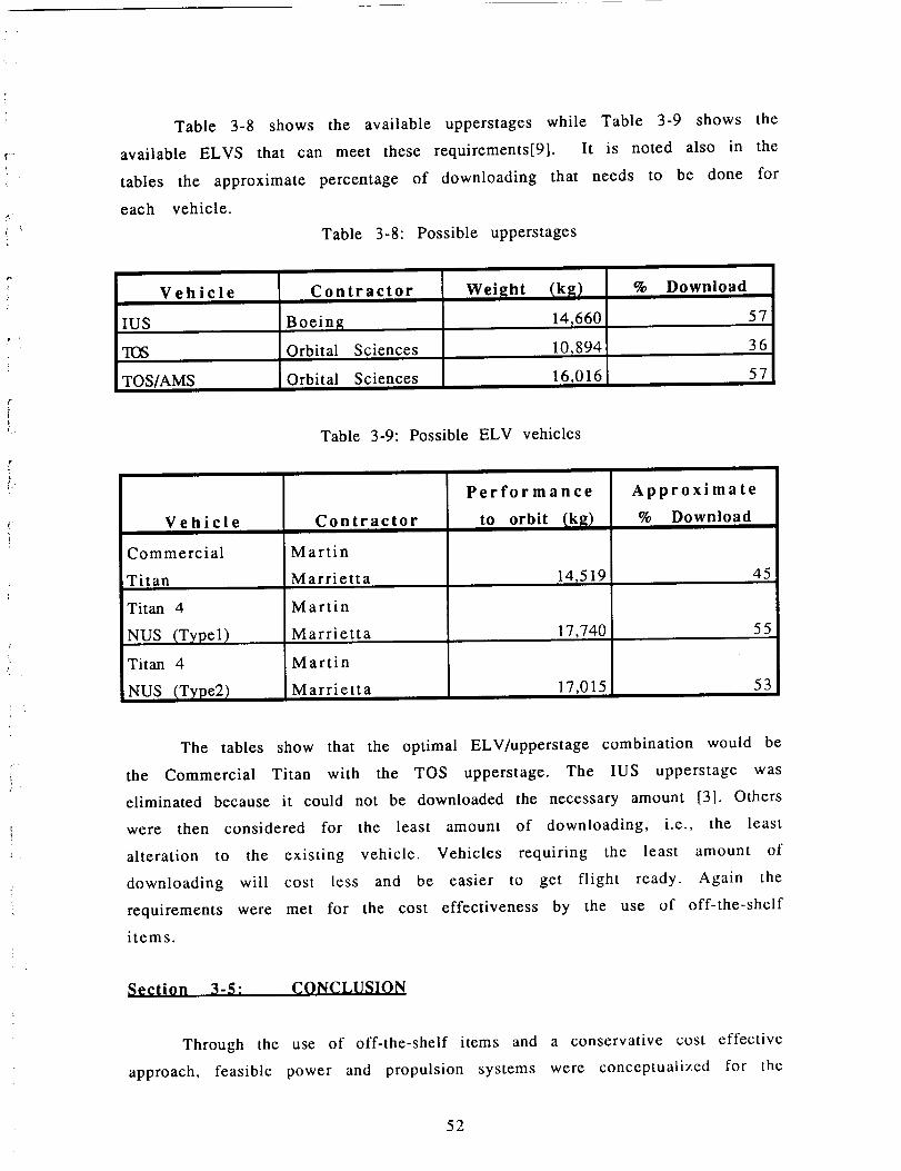
Table 3-8 shows the available upperstages while Table 3-9 shows the
available ELVS that can meet these requirements[9]. It is noted also in the
tables the approximate percentage of downloading that needs to be done for
each vehicle.
Table 3-8: Possible upperstages
Vehicle
IUS
q-OS
TOS/AMS
Contractor
Boeinl_
Orbital Sciences
Orbital Sciences
Wei_[ht
14_660
10,894
16,016
% Download
57
36
57
Table 3-9: Possible ELV vehicles
Vehicle
Commercial
Titan
Titan 4
NUS (Typel)
Titan 4
NUS (Type2)
Contractor
Martin
Marrietta
Martin
Marrietta
Martin
Marrietta
Performance
to orbit _k_t
14_519l
17,7401
17,015
Approximate
% Download
45
55
53
The tables show that the optimal ELV/upperstage combination would be
the Commercial Titan with the TOS upperstage. The IUS upperstage was
eliminated because it could not be downloaded the necessary amount [3]. Others
were then considered for the least amount of downloading, i.e., the least
alteration to the existing vehicle• Vehicles requiring the least amount of
downloading will cost less and be easier to get flight ready. Again the
requirements were met for the cost effectiveness by the use of off-the-shelf
items.
Section 3-5: CONCLUSION
Through the use of off-the-shelf items and a conservative cost effective
approach, feasible power and propulsion systems were conceptualized for the
52

j -
Cerberus spacecraft. It is believed that these systems will not preclude
Cerberus from successfully completing its mission along with possibly
performing others. It is also believed, from a cost standpoint, that these
systems will not cause Cerberus to overshadow other missions of the same era.
References
1. Campbell, R. W., "Space nuclear power safety from a user'sviewpoint", Space Nuclear Power Systems, 1984, p. 515.
, Chmielewski, A.B., "Improved techniques for predictingspacecraft power", IECEC, 22nd Intersociety Energy ConversionEngineering Conference, August 10-14, 1987, p.392.
.
.
Cole, "Phase A report preliminary assessment of space transportationalternatives for planetary missions," Launch vehicle alternative,
performance, availability and schedule. JPL D-3332 JPL NASADocument, May 15, 1986.
Garrison, P.W., "Advanced propulsion for future spacecraft", AIAA81-1534R, AIAA/SAE/ASME 17th Joint Propulsion Conference,Colorado Springs, CO.,July 27-29, 1981.
. Iserland, K., "Overcoming the launch crisis: A challenge for ELVs",ACTA Astronautica, Vol. 20, pp. 9-19, 1989.
. Koelle, D. E., et al., "Cost reduction for future communication
satellites by a standardized propulsion module (SPM)", ACTA,Astronautica, Vol. 17, No. 4, pp. 397-405, 1988.
. Koepke, A., "AAE 241 Class notes", University of Illinois, Kinkos216.05, 1990.
Packet
.
.
Schock, A., "Modular Isotopic Thermoelectric Generator", FairchildSpace and Electronics Company, Germantown, MA. 20769, 1980.
No author, "Aerospace Forecast and Inventory"
Aviation Week and Space Technology, pp163-173, March 19, 1990.
53

Annendix C: EOUATIONS
EOUATIONS FOR POWER CALCULATIONS
Using the power law equation:
i
p=ce kt
and using conditions found in ref.[2] for 238puO2
eq. 1
1.5493 years later
t(0)= 4460.6 watts
t(1.5493)=4406.7 watts
the constant (k) for 238puO2 was found to be -7.8468E-3
Now plugging the conditions of c=initial thermal loading of
258.5 watts from Figure 3-4 for an eleven slice MITG and t=19, the power
after 19 years is 222.69 watts.
EOUATIONS FOR PROPELLANT CALCULATIONS
Using the rocket equation:
A v=(Isp* g)*ln(minit/m final) eq.2
and the propellant mass fraction:
mpropmass frac=mprop struc.+prop
eq.3
masses were found.
For Hydrazine: Isp=235 mass frac.=.9
For Ammonium Perchlorate (70%)'
unusable=2.5%
Isp=2 mass frac.=.92 unusable=2%
54

EOUATION_ FOR CALCULATIONS OF TIME OF BURNS
A simple linear approach was taken using the following:
F=ma eq.4
t
to get the acceleration (a) and the linear velocity equation:
Av=at eq.5
The change in mass was accounted for at the end of each burn,
then subtracted from old to get new mass for next burn.
*It is noted here, that in reality (a) is not constant throughout the burn
since the mass is also changing as fuel is expelled from
the spacecraft. Iterating numerically would yield smaller times
since the rocket effect would occur. Therefore, this linear
approach is a rough but conservative estimate.
i •
55

r
Section 4: ATTITUDE. ARTICULATION. AND CONTROL (AACS)
Section 4-1: INTRODUCTION
The function of the Attitude and Articulation Control Subsystem (AACS)
is to determine the orientation of the spacecraft and control its motion. This
includes orienting the axes of the spacecraft; controlling the valves, heater,
and firing of the thrusters; firing the engine for trajectory correction
maneuvers (TCM); and controlling the science platform [1].
The design of the AACS was determined largely by the requirements in
the Request for Proposal (RFP). The requirements that applied specifically to
the design of this subsystem were satisfied. First, it was required that the
spacecraft's performance, weight, and cost were optimized. Second, the
spacecraft was designed to be simple, reliable, and easy to operate. Third, off-
the-shelf hardware and technology available by 1999 were used as much as
possible. Fourth, the spacecraft was designed to be able to perform several
possible missions. Fifth, the spacecraft will have a design lifetime sufficient to
carry out its eighteen year mission plus a reasonable safety margin. (A 20%
safety margin would result in a design lifetime of 21.6 years.)
In addition to those in the RFP, there were design requirements dictated
by the other subsystems. The Command, Control, and Communication (CCC)
Subsystem required that the high-gain antenna must be pointed at the Earth
with 0.1 ° pointing accuracy. The Science Subsystem needed to be able to point
remote sensing instruments at specific locations for extended periods of time
with 0.1 ° pointing accuracy. The Mission Planning Subsystem required that
windows must be identified in which the AV maneuvers could be executed, and
the Power and Propulsion Subsystem defined limits for the power consumption
and mass of the AACS.
Finally, the AACS was also designed to follow the overall objective of the
Cerberus mission. Cerberus was designed to sell and work, which means that at
every turn, measures were taken to design an AACS that was cost effective and
truly feasible.
£
56

Section 4-2: MAJOR FEATURES OF THE AACS
After careful consideration between three-axis, spin, and dual-spin
control, three axis stabilization was selected as the control method for
Cerberus. Spin stabilization met many of the requirements. It is the simplest
and least expensive of the three [2]. It is very reliable and has a long lifetime,
which is very important considering the length of this mission (eighteen
years). In addition, it is the lightest and requires the least power [3].
Nonetheless, spin stabilization was unacceptable for one reason. The Cerberus
mission requires that the remote sensing science instruments be inertially
fixed for extended periods of time. This would require the spacecraft to
undergo a complicated despinning process, which makes spin control
infeasible. On the other hand, both three-axis and dual-spin provide the
neccesary fixed inertial orientation. Dual-spin has certain advantages over
three-axis. The former provides scanning science capabilities and has low
sensitivity to disturbances, whereas the latter has neither [3]. The deciding
factor between the two, however, was the fact that dual-spin is much more
expensive and complex than three-axis. Although dual-spin offered certain
conveniences, it did not meet the requirements of optimizing cost and
maintaining simplicity. Therefore three-axis stabilization was selected. Table
4.1 compares the advantages and disadvantages of the three control methods
discussed above.
Table 4-1: Comparison of Control Methods
rypes of Control
Three-Axis
Spin
[2, 3]
Advantages,High accuracy,Good maneuverability
,Adaptable to changingmission requirements
Allows inertial remote
sensing science
,Simple, low cost,High reliability, long life,Low weight and powerInherent science scan mo-tion
,Low sensitivity to distur-bances
Disadvantages• High weight and power• Costly hardware•Extensive fault detec-
tion/correction for back-
up
• Poor maneuverability
• Must despin to do someimaging science, which iscomplicated process
57

Dual-spin
Provides both scanning _Expensive and complexand inertial science ].Articulated elements re-
Low sensitivity to distur- | quire balance compensa-
bances / tionFixed inertial orientation
After the decision was made to use three-axis control, the next step was
to decide how to best implement such control. There were two options. Thefirst was to use momentum wheels or control moment gyros for stability andsmall turns. A reaction control system using gas thrusters would also beneeded to dump momentum from the momentum wheels or control momentgyros and to do large turns and maneuvers. The second option was to only usegas thrusters. A trade study was conducted to see if the addition of momentumwheels or control moment gyros would save enough fuel to offset theadditional weight. First, it was concluded that momentum wheels are lighterthan control moment gyros [2], so momentum wheels were used as the basis ofcomparison. From three different sources[2, 4, 5], the mass of a system of fourmomentum wheels was estimated at 100 kg. Next, the mass of the fuel thatwould be saved by using momentumwheels was calculated to be 80.6 kg. Seeequation (1) in Appendix D for details of this calculation. Therefore, evenwithout considering the additional fuel needed for momentum dumping, usinga system with only thrusters would be lighter than one that used boththrusters and momentum wheels. See Table 4.2 for a summary of this tradestudy.
Table 4-2: Trade Between Momentum Wheels and ThrustersSystem with both momentum
wheels and thrustersSystem with thrusters only
mass (kg) 80.6 100.0"*Does not include fuel needed for momentum dumping
In addition to being heavier, momentum wheels would also add unnecessarycomplexity and would decrease the lifetime due to wear. Therefore, three-axiscontrol will be implemented using a configuration of only thrusters becausesuch a selection satisfies the requirements of simplicity, sufficient lifetime,and low weight.
58

The last major feature in the design configuration of the AACS is thearticulation control of the science scan platforms. The Science Subsystemrequires both a high accuracy scan platform with two degrees of freedom anda low accuracy platform with one degree of freedom. Two options wereexplored. The first was the traditional method, in which scan platforms arearticulated using two step motor actuators without any momentum compensa-tion [6]. In addition, the AACS electronics, star tracker, and gyros are allplaced on the spacecraftitself. This was the technology used for Voyager. Thesecond option involves a new technology being developed for the MarinerMark II (MMII) project, and it is called the Integrated Platform Pointing andAttitude Control Subsystem(IPPACS). If the second option were used, the startracker, gyros, and AACS electronics would all be placed on the scan platform[7]. This second option using IPPACS was selected for the following reasons.First, the scan platform momentum compensation decouples the scan platformdynamics from those of the spacecraft [7]. Second, this decoupling of thedynamics ensures dynamic stability of the spacecraft [8]. This satisfies therequirements of reliability and ease of operation. Third, the high accuracysensors and controls are rigidly attached to the high accuracy scienceinstruments, which greatly reduces many errors found in systems like that onVoyager [7]. See Table 4.3 for a comparison of errors between Voyager andMMII IPPACS. This meets the requirement to optimize the spacecraft'sperformance.
Table 4-3: Comparisonof Errors BetweenVoyager and MMII IPPACS in Termsof Scan Platform Pointing Control (Adapted from [71)*
Limit Cycle
Error Source
Sun Sensor
Star Sensor
Scan Platform Control
Structural Misalignment
Dynamic Stability
Gyro Drift (2 hours)
Total 3c Scan Platform Pointing Accurac Y*All numbers in mrad
0.69
0.59
1.20
MMII IPPACS
0.00
0.00
0.02
0.34
0.58 0.58
0.33 0.33
0.00 0.11
2.26 0.76
59

0 -
Because IPPACS has such high accuracy, it will easily be able to perform
several possible missions. Although IPPACS has yet to be flight tested, it will
have flown aboard a Mariner Mark II mission before 1999, and can be
considered off-the-shelf hardware. The biggest disadvantage of IPPACS is that
it shifts the weight of many of the attitude control components away from the
center of mass to the scan platform, slightly increasing the moments of inertia
of the spacecraft [7]. Nonetheless, the advantages far outweigh this disadvan-
tage, and IPPACS was selected to control the articulation of the high accuracy
platform. Figure 4.1 shows a schematic of the IPPACS configuration, and
Figure 4.2 shows the actuator orientation for two articulation degrees of
freedom.
The question still remained of how to control the articulation of the low
accuracy platform. One option was to use IPPACS on it also, and therefore have
a fully redundant AACS. This, however, would certainly not optimize weight
and cost. Instead, it was decided to use a single uncompensated step motor
actuator and measure the angular displacement with a simple optical sensor.
Momentum compensation wasn't necessary because the low accuracy platform
will not be used for determining the attitude of the spacecraft or conducting
imaging science. Instead, it will be used merely to scan free space. The
absence of momentum compensation will, however, lead to some disturbance of
the spacecraft which must be corrected by firing the thrusters. This will still
be lighter and less expensive than including a momentum compensation
wheel and thus meets the RFP requirements of optimizing cost and weight.
6O

jr.-
CONSTIU_IN1"$
• _OCK F;X_ ;N $fC• CONEJ. TOCLOCK
• I. J. tAXES FIXEOIN PLATFORM
• ALLAXESTHROUGHPLATFORMC.M.
• Ijj • Ikl_
Figure 4-1: IPPACS Configuration (Adapted from [8])
WH£E). r'_
STEPMOTOR
Figure 4.2" Actuator Orientation for Two Articulation Degrees of Freedom
(Adapted from [8])
61

i
f
Section 4-_-" HARDWARE SELECTION AND PLACEMENT
After the decision was made to use thrusters for attitude control, the
next phase was to select thruster size and placement. With the use of IPPACS
technology, turning rates of less than 1.3 deg are desired. From preliminarysec
data on the moments of inertia and thruster lever arm distances, 0.9 N
thrusters were found to produce a turning rate of 1.261 (leg which meets theSeC '
specification. See equation (2) of the Appendix. The 0.9 N thrusters were
selected because in addition to meeting turning rate specifications, they are
off-the-shelf hardware, being previously used on both Voyager [9] and MMII
[7]. Hydrazine was selected as the fuel so that these thrusters and the 400 N
engine could be supplied by the same fuel source. This satisfies the
requirement of simplicity.
The thrusters were placed in such a way as to provide a torque couple
around each axis in both directions of spin. This is required for three-axis
control. Such a configuration requires four thrusters per axis, or twelve
thrusters total. Figure 4.3 illustrates the placement of the thrusters with
respect to the principal axes of the spacecraft. Only the minimum number of
thrusters necessary was used for this configuration, which appears to
sacrifice reliability and redundancy for the sake of optimizing weight and
cost. This, however, is not actually the case. The thrusters themselves have
proved very reliable on past missions; most problems occur in the plumbing,
valves, and heaters which are redundant on Cerberus. The details of this can
be found in the Power and Propulsion Subsystem in Section 3. Also, the
thrusters were carefully placed to ensure that
62

! •
{
t
r
k
÷ z (RolO
\I/
/I\+X (Pitch)
\
/\
//
\1/
/1\\1/
+Y (Yaw)
/1\
Figure 4-3: Placement of the Thrusters With Respect to the Principal Axes of
the Spacecraft
their exhaust would not damage any of the science instruments. Refer to the
Structures Subsystem in Section 2 for a picture showing thruster locations
relative to the scan platforms.
The Planetary ASTROS (Advanced Star/Target Reference Optical Sensor)
was selected as the star tracker for Cerberus. Its accuracy of 4 arcsec (0.001 °)
exceeds the required pointing accuracy of 0.1 ° [7]. The Planetary ASTROS has
the additional benefit of being able to track other targets, so it will also be used
to locate Pluto and Charon. In addition, it has the lowest weight and power
requirements of any star tracker currently available (the Voyager Canopus
Tracker is no longer manufactured) [7]. There is, however, one problem area.
Although the Planetary ASTROS is internally redundant and has the longest
lifetime of any star tracker currently available, its design lifetime of ten years
falls dreadfully short of the required 21.6 years [7]. Nonetheless, the best plan
of attack is to select the Planetary ASTROS and continue to work on increasing
its lifetime through design modification. A comparison of the characteristics
63

of the Planetary ASTROS, Canopus Tracker, and the Digital Standard StarTracker (DSST) are given in Table 4.4.
Table 4-4:
(Adapted from [7]
Canopus
Comparison of Star Tracker Characteristics
Parameter
'Field-of-View (degrees /
_Spin (drift_ Rate (deg/sec)
Calibrated Accuracy (arcsec)Multistar Measurement
Internal Redundancy
Tracker9x36
N/A180
DSST8x8
<0.3
Planetary ASTROS
llxll
< 0.5
Mass (k_q)
Power (W)
10 4
NO NO 3 stars simultaneouslyNO NO
8.2
20.0
4.3
4.5
YES
8
11
The Planetary ASTROS will be placed on the high accuracy scan
platform as necessitated by IPPACS. It will be boresighted with the science
instruments to enable accurate pointing of these instruments. Furthermore,
placement of the star tracker on the high accuracy scan platform allows the
Planetary ASTROS to track stars and other objects without requiring the
rotation of the entire spacecraft. This will save AACS fuel and optimize weight
and cost. Because the Planetary ASTROS is already being developed for the
MMII, Cerberus will reap the benefit of a recurring cost as opposed to
spending money to develop a new technology. In addition to meeting the
requirement of optimizing performance, weight, and cost, the Planetary
ASTROS also qualifies as off-the-shelf hardware.
In selecting the components for the Inertial Reference Unit (IRU),
there were found to be two general choices: flight-tested mechanical gyros or
a new gyro based on fiber optics called the Fiber Optic Rotation Sensor (FORS).
One source states, "FORS is attractive for space missions because it promises
performance comparable to or better than that of mechanical gyros as well as
significant improvements in lifetime, weight, power consumption and cost"
[10]. As with the Planetary ASTROS star tracker, the FORS lacks flight
experience and a sufficient lifetime. Nonetheless, it is still the best available,
having a longer lifetime than any mechanical gyro because there are no
moving parts in the FORS [7]. Clearly, an optical gyro such as FORS best meets
the requirements. The question remained, however, of which optical gyro was
best. Of the three optical gyros studied, FORS best optimized performance
64

(lowest drift and rate noise, and best angular resolution), lifetime, power, andweight. Table 4.5 gives the numerical data for these parameters.
Table 4-5: Optical Gyro CharacteristicstAdapted from [7])DRIRU II CG-1300 Laser Gyro
FORS0.2E-3
Parameter
Residual Drift Rate (deg/hr)
Rate Noi'se (deg/sec)
7.0E-3
1.0E-5 40E-5
Angular Resolution (arcsec) 0.005 0.05 1.4
3 310
< 10"
10
MTBF (yr)
Power (W)Mass (kg)
Volume (in 3)
*For three units
22
11
990
18
18
3501000
In addition to meeting the above stated requirements, the FORS will be off-the-
shelf before 1999 because it is tentatively scheduled for use on the MMII
project. For these reasons, Cerberus will use FORS for its IRU. Two identical
sets of three (one for each axis) will be placed on the high accuracy platform,
making the IRU redundant [7]. This is to fulfill the requirement of reliability.
A sun sensor will be mounted behind the high-gain antenna and will be
pointed at the sun through a hole in the reflector. As with Voyager, it will be
boresighted at an offset of 5-6 ° off the Z (roll) axis of the spacecraft, so that
when the sun sensor points at the sun, the antenna points at the Earth, as
required by CCC [6].
At this point in the preliminary design, there was no way to calculate
the precise A V required for a minimum maneuver scheme. Instead, a
calculation was performed based on an average of AACS maneuvers per month
in past missions. This calculation is given in equation (1) of the Appendix.
The result is that 80.6 kg of hydrazine will be required for AACS maneuvers.
This does not include TCM's.
To conclude the discussion on hardware selection and placement, Table
4.6 gives a summary of the power and mass requirements for the AACS.
65

,i
Table 4-6: Power and Mass Requirements for the AACS
ComponentPlanetar), ASTROS Star TrackerFORS IRU (3-axis r redundant)
,Digital Sun Sensor
[Microstep Scan Actuator
Low Accuracy Platform Actuator
Low Accuracy Platform Position SensorHeating valves and thrustersTotal*
2
Power (W)
11
10
19
Mass
Ik_)8
10
4
21
1 7 6
1 1 0.5
12
*Does not include computer, propulsion system, or fuel
7
60
15
64.5
Section 4-4: SCANNING AND POINTING REOUIREMENTS
IMPLEMENTATION
By pointing the sun sensor at the sun and the star tracker at a star
orthogonal to the roll axis, the high-gain antenna can be pointed at the Earth
with 0.1 ° accuracy as required by CCC. From this orientation, the low accuracy
scan platform can perform particle field science around its one degree of
freedom; the Science Subsystem did not deem it necessary to perform such
experimentation around all three axes. From this same celestial lock
orientation, much of the science on the high accuracy scan platform can be
accomplished. The star tracker will be used in this situation to track the
targets of the science instruments. If an object cannot be sighted from
celestial lock, the entire spacecraft will be rotated using the 0.9 N thrusters,
with the attitude controlled by the IRU. With this configuration, the remote
sensing and imaging science can remain fixed on a target in any direction for
extended periods of time (approximately three hours) as required by the
Science Subsystem.
Section 4-5: ATTITUDE CONTROL MODES
After Cerberus separates from the launch vehicle, the AACS will enter
the deployment mode. During this time the AACS will control the deployment
of the magnetometer, RTG's, science scan platforms, and high-gain antenna
66

i"
[9]. All the hardware and instruments will be checked out and calibrated in
order to optimize performance.
When the checkout and calibration is complete, Cerberus will enter the
cruise mode. During this mode, the AACS will execute a preset series of
commands to measure fields and particles of interplanetary space [9] after
every A.U., as required by the Science Subsystem. Other procedures executed
during this mode are attitude determination, high-gain antenna pointing [1],
and maintenance of all three axes within a deadband limit of 0.05 ° [6]. This
mode would also include a special routine in both the computer RAM and ROM
to point the antenna back to the Earth from any other orientation. This
enhances the spacecraft's reliability and ease of operation.
Finally, Cerberus will enter its flyby mode when it encounters Earth,
Jupiter, and finally Pluto. At Earth and Jupiter this will involve the AACS
recognizing a box-shaped window defined by certain stars in which it will
control the firing of the 400 N engine. During the approximately fifty day
encounter near Jupiter and Pluto, the AACS will control the pointing and
slewing of the high accuracy scan platform.
Section 4-6: CONCLUSION
The AACS of Cerberus will use a three-axis stabilized design controlled
with 0.9 N hydrazine thrusters. The high accuracy scan platform will be
controlled using the new IPPACS concept which offers the tightest pointing
and the most reliable control. All components were selected to optimize
performance, weight, and cost and will be readily available by 1999. The AACS
has also been shown to meet the requirements imposed upon it by the other
subsystems. The critical problem areas left to be solved are extending the
lifetime of the components to at least 21 years (20% safety margin) and de-
signing the details of the attitude control modes and the exact sequence of
AACS commands.
67

References
1. Galileo: Exploration of Jupiter's System, NASA SP-479.
2. Wertz, James, ed. Spacecraft Attitude Determination and Control.
3. Gates, Robert L. AACS lecture. {AAE 241 class notes on 3/22/90}.
. Kendig, John. R. and Davis, Porter. "Space-qualified 1000 Foot pound-second
Magnetically Suspended Reaction Wheel Assembly (MSRWA)." Guidance
and Control 1981, Vol. 45 of Advances in the Astronautical Sciences.
5. Research and Technology 1986. NASA Goddard Space Flight Center.
6. Voyager Neptune/Interstellar Mission.
Mission Systems Handbook.
Flight Science Office, Science and
7. Draper, Ronald F. The Mariner Mark II Program, AIAA-84-0214.
Propulsion Laboratory, Pasadena, CA.
Jet
. Bell, C. E. and Stanton, R. H. InCr_ially Referenced Instrument Pointin_
Platform with Moment_lm Compensated Articulation. Proceedings of the
SPIE National Symposium and Workshop on Optical Platforms, Vol. 493.
9. Adamski, Terrence P.
AIAA-87-0501.
Command and Control of the Voyager Spacecraft,
10. De Paula, R. P., et al. Fiber Optic Rolation Sensor for Space Missions.
Proceedings of SPIE, Vol. 838, Fiber Optic and Laser Sensors V (1987).
68

aammaLr_-12
m l = mass for small AACS maneuvers
= 0.373 kg {from [6]}month
0 kg y12 monthS'_l 8 years)masstot = .373month_. 1 year f
= 80.6 kg eqn. (1)
2_ Ct?0c =-i"_-v t_" ) {from [3]}
eqn. (2)
69

?
Section 5: COMMAND. CONTROL AND COMMUNICATION
Section 5-1: INTRODUCTION
For the Cerberus mission, communication between the spacecraft and
Earth becomes the primary driver for the Command, Control and
Communication (C 3) subsystem. Due to a time lag as high as 11 hours (round-
trip), the craft has been programmed for a high degree of autonomy. Using as
much off-the-shelf hardware as possible, it will use the latest in computer
technology, and utilize a spare 4.8m Galileo antenna. The receiving antenna
system will be the existing Deep Space Network (DSN). Decisions were reached
based on previous missions and the requirements specific to the proposal.
Section 5-2: COMMAND AND CONTROL
Consisting primarily of the computer, Command is divided into three
main subsystems Computer Command Subsystem (CCS), Attitude And
Articulation Control Subsystem (AACS), and Flight Data Subsystem (FDS). Each
subsystem will utilize expert systems when available, as well as sophisticated
fault protection algorithms, (FPA). Due to the distance involved and the length
of the mission (18.7 years) the spacecraft is designed to be almost fully
autonomous.
Command will be performed by two computers in parallel redundancy.
Each computer will consist of five central processing units (cpu) with math
coprocessors, all accessing a common memory chunk of 64 megabytes (MB).
One cpu designated as the monitor will break each assignment into subparts
and allocate them to the other four cpu's. The monitor will also serve as a fault
detector should one of the cpu's fail. In this case, an FPA will be used to
exclude that cpu. In the event that an entire computer fails, the cpu's in the
remaining computer can be reprogrammed so that they are working in
redundant pairs. In a worst case scenario, the whole spacecraft could be run
from one cpu.[17]
The maximum bit-rate for Cerberus is 145.5 kbps. Science
instrumentation may require up to 1000 kbps. Real-time transmission, then, is
not always feasible. Data must be stored until transmission is possible.
External memory is needed.
70

,t
f
Three options exist for external memory magnetic tape, removable
hard drives or optical disks.J6] Although not proven as space technology,
optical disks provide a compact, cost efficient, error-free method for storing
data. It will have read-write capabilities, with a maximum storage capacity of
600 MB. See Table 5-1.
Table 5-1" Comparison of External Memory Options
External Memor]¢
Magnetic Tape
Removable Hard drive
Optical Disk
Disadvantages
Bulky, error-prone,
heavy.
Not proven tech., high
power cost_ heavy.
Not proven tech.
Advantages
Proven technology,
inexpensive.
Small, low error rate.
Small, lightweight, low
error rate.
Three options also exist for the computer programming language.
Assembly is the lowest level language of the three, and as such is difficult to
program in. C is an industry standard. Many people are familiar with it and
programming is much simpler than with Assembly. For this mission, ADA was
selected. The standard for the Defense Department, it is ideal for situations
where prioritizing is needed. Semaphores, which act as flags, signal
important incoming information, allowing new information or more
important processes to take precedence over existing tasks. This is ideal for
sequencing.[ 17]
Each computer will be able to access the optical drive. The computers
and the optical drive will be fully independent and redundant, in case of
failure. In this way, a computer could be reprogrammed from either the
optical drive or the other functional computer. The computers and optical disk
will be redundantly programmed for the three subsystems CCS, AACS, and
FDS.[1]
71

Section 5-2.1: COMPUTER COMMAND SUBSYSTEM
As overseer of the craft, CCS is primarily concerned with issuing
commands to the other subsystems. Other responsibilities include sequencing,
FPA's and real-time command processing.
Sequencing will function throughout the duration of the mission, but
becomes more important when science instrumentation is active. It assigns
each function a value based on priority. This priority is determined before the
mission's onset. Considerations include, but are not limited to, whether science
cannot be achieved from Earth, capability of the instrument(s) required, the
number of observations needed, duration and time of the observations, power
needed, and tolerance of location and duration. A program such as SEQTRAN
will be implemented.[22] This program converts input into mnemonic
commands and checks for constraint violations. Two constraints are
spacecraft physical limitations and mission rules established for safe
operation of the spacecraft. Maximum efficiency of sequencing space is
achieved by overlap. This allows one sequence to start before a prior sequence
is finished.
Expert systems will be used wherever possible. These allow on-line
changes to be made in the structure of craft operations without input from
ground control. Each system must consist of knowledge representation,
knowledge utilization, and a computational model.J29] These will be further
broken down into a data handler and trend analyzer.J7] The data handler
receives data from telemetry and stores it appropriately, according to
significance at that particular time. The trend analyzer calculates, plots and
posts trend information. Use of expert systems will provide better fault
protection, allowing quick response to potential problems.
Improved fault detection will enhance the craft's ability to successfully
achieve mission goals. FPAs will consist of five major modules the main
controller, status monitor, fault diagnosis module, knowledge base, and
interface handler. These five modules will work together as an expert system
to detect errors early on and take preventative actions when possible. The
craft's autonomy will be increased by reducing the amount of ground control
intervention.
72

CCS is responsible for enabling all telemetry commands. It will alsoprocess real-time commands and send them to AACS or FDS as needed,monitoring them as well as other craft operations.
Section 5.2.2: ATTITUDE AND ARTICUL_,TION CONTROL SUBSYSTEM
¢
Utilizing an expert system such as APPS, AACS will hold the craft to its
chosen trajectory. In order to maintain communication with Earth, the high
gain antenna (HGA) must always point to Earth. This will be done by attitude
maintenance, antenna pointing, and gyro control. Antenna pointing control
will be divided into a main reflector and a subreflector drive.[13] More
information is contained in the Attitude and Articulation Subsection.
iSection 5-2.3: FLIGHT DATA SUBSYSTEM
.
¢.
Responding to commands from the CCS, the Flight Data Subsystem
contains routines that control science instrumentation and the optical drive.
Some data processing is also handled through FDS.
FDS first collects engineering and science instrument data. This is used
to control the operation of the instruments. It is then formatted for either
storage or real-time transmission. Analog data must be converted to digital
form before it can be sent. This is also handled by the FDS. FDS must provide
data modes, rates and formats. FDS also provides frequency references for the
other subsystems.[ 19]
A system will be utilized using movable blocks of observations. These
groups are controlled relative to a single adjustable starting time, which
allows the computer to compensate for inability to determine the time of
closest approach in time for effective trajectory control maneuvers.[8]
Section 5-3: COMMUNICATIONS
Communications will consist of two subdivisions - Telemetry and the
Radio Frequency Subsystem (RFS). Ground commands will be processed
through RFS and passed on to CCS. Information is also relayed back to Earth
through the RFS by telemetry.
73

Section 5-3.1: TELEMETRY
Telemetry is made up of information from three different sources.
Science data is generated by instrument observations. While only small
amounts of science data are created, it requires the highest quality
transmission accuracy. Engineering data, for daily craft operation, requires a
moderate quality transmission of moderate volume. Imaging data, due to its
high redundancy, has a very high volume with the lowest quality standard.
In order to minimize data rates, all data that can be compressed shall be.
Both convolution and Reed-Solomon (RS) coding will be used, reducing bit
errors down to 10-6.[6] Although RS coding requires more processing at the
ground end, it is more effective and efficient than the Golay coding originally
used for the Voyager missions.[14] An RS system consists of one chip for the
encoder and seven chips for the decoder. It operates at a rate up to 80 Mbps.[3]
All, or nearly all pertinent data is retained.
Loss of information can also be reduced through multiple playbacks•
The memory capacity of the computers is high enough that the computer can
wait for data confirmation from Earth. If a high loss has occurred, data is
merely retransmitted.
Information will be sent in telemetry packets. Packets will be
constructed by individual subsystems. The CCS will add RS code bits to the
packets, providing error-free transmission.[6] Due to the large quantity of
memory, data loss can be further minimized.
74

Section 5-3.2: RADIO FREOUENCY SUBSYSTEM
Similar to the Cassini mission, Cerberus takes advantage of the more
powerful Ka-band (32 GHz). Although the antenna surface tolerances are
lower for higher frequencies, technology exists that will compensate for this.
This will include the addition of Ka feeds, waveguides and amplifiers. Ka-band
transmission simplifies hardware by decreasing size and power requirements.
Bit error rates and doppler tracking accuracy are also improved.J6]. A net gain
of 8 db can be realized by upgrading from X-band to Ka, as antenna gain
increases in proportion to the square of the link frequency. [ l l] .
For further efficiency, the command detection unit (CDU) will be under
RFS jurisdiction. Its uplink command will be performed by the Ka-band
transponder. Technology exists allowing the telemetry modulation unit (TMU)
functions to be accomplished with a few chips. This too will come under the
RFS umbrella. [6]
Optical communications were also considered. Unfortunately, under the
proposal time limit, optical communication is not possible.[31] If developed, it
would have many advantages over the traditional RF system. Its wide
bandwidth would allow gigabits of information to be transmitted via a small
laser antenna with low transmitting power. However, the pointing accuracy
requirement alone, 10 -4 degrees, disqualifies it from use - the best accuracy
achieved today is 0.1 degrees. Output powers must be increased, as well as
improved beam quality. Materials must be found that are radiation tolerant.
Space debris is an additional factor, as it can damage the optics and will cause
an inferior signal quality.J4] For all these reasons, a traditional RF system was
judged to be best (Table 5-2).
Section 5-3.3: SPECIFICATIONS
For an RFS to meet the challenges of this mission, new techniques must
be employed. The Galileo antenna had the advantage of being made of a light-
weight mesh material. Its folding capabilities allow many different launch
possibilities. However, in the ten years since the antenna was developed, new
technologies have provided different ways to improve upon its design.
Before we can use the Galileo antenna, it must be modified. New
technology allows us to transmit at the higher Ka-band frequency. Offset
75

ii
r
;k .
subreflectors must also be added, to allow X- and S-band transmission. These
subreflectors will have frequency selective surfaces (FSS), allowing
transmission of several different frequencies from one antenna with the
addition of multiple feeds.[15,33] The antenna will be attached to a three-way
gimballed joint to allow it to be pointed in any direction. Sitting "on top" of the
craft, it will always be pointed at Earth, except in cases where the spacecraft
must be turned to perform science experimentation. The low gain antenna
(LGA) will also transmit at Ka-band. It will be used to communicate with Earth
until Jupiter is reached. The high gain antenna will be deployed at that time.
Table 5-2: Communication Options
Communication Mode
High gain antenna and Low
gain antenna
!Optical Communications
Disadvantage
Higher weight and cost.
Relatively high power
requirement.
Not yet developed.
Advantage
Higher redundancy,
allows delayed
deployment of HGA.
Proven technology.
Extremely lightweight
and power efficient.
Although bandwidths are traditionally 5-10% of the transmitting
frequency, the antenna is designed with a 21.85KHz bandwidth. This is
approximately 7E10"5% of the 32 GHz transmitting frequency. Additional feeds
must be used, as well as amplifiers and waveguides.
The antenna system must also be designed around a number of other
factors. DC to RF conversion (Lt or transmitter system losses) is currently
21%.[11] Attenuation, which increases with inclement weather, must also be
considered (Figure 5-1). Using Goldstone as the receiving station, one has an
atmospheric attenuation (La) of 92%.[27] Antenna efficiency, g,can be pushed
as high as 80%.[33] Other losses include receiver system losses (Lr), pointing
losses of both the transmitter and the receiver (Ltp and Lrp, respectively),
free space loss (Ls) and polarization loss between antennas (Lp). A
transmission power (Pt) of 10 W results in a receiving power of 9.05"10" 17
W.[30]
76

""1
"i
r= ,_ol
| l I l' | | I I I
IBEST
._ DSTONE
_AN_ERRA/MAORIO
oo_ I f 1 I I I I I0 10 20 30 40 50 60 70 80 90
K= _AND _ 31SE TEMPE RATURE, K
f
i Fig.6-1: Ka-band atmosphericnoise temperature statistics: all
f sites, 30-deg elevation angle.[ 27]
fl__pOr:_OI;C
_._f_ec for
r , I/X ,_
Reflector
Fig.6-2: Multiple feeds for
different frequency bands can be
arranged with beam waveguides,
and frequency selective
surfaces. [ 15 ]
L,
DSN will be the receiving antenna. This requires a signal-to-noise ratio
(SNR) of at least 10, with higher values providing better transmission.[30] All
my calculations are based on the current 70m antenna with an SNR of 20. Vast
improvements in receiving power will be realized when the proposed array of
35m antennas is deployed. Other improvements could be made by orbiting a
receiving dish. Gravity effects would not be felt and atmospheric attenuation
would be eliminated. The dish could either be an orbiting satellite or a multi-
deployable dish on the space station.
Section $-4: CONCLUSION
As few as ten years ago, the idea of a mission to Pluto would have been
ludicrous. It is only with recent advances that this mission has become
feasible. Without the ability to transmit at a higher frequency or use an
upgraded DSN, the antenna size alone would have precluded a successful
venture. Recent advances in materials such as Kevlar or optical disks further
decrease the size and weight of the craft. All of this adds up to a smaller, more
77

cost-efficient operation, able to explore not just Pluto, but other planets as
well.
78

References
¢
°
,
°
°
,
°
.
°
°
10.
11.
12.
13.
14.
15.
Adamski, Terrence,"Command and Control of the Voyager Spacecraft"AIAA paper 87- 0501.
Casey W.L., Doughty G.R., "Laser Communications System Design," SPIEvol. High Data Rate Atmospheric and Space Communications, Sept. 1988,
pp.28-35.
Cellarius, Mark R., "Data Compression for Data Acquisition,
Storage and PCM Transmission", Vol. 23, 1987 InternationalTelemetering Conference, San Diego Ca, pp. 517-24.
Chen C.C.,Schwartz J.A. "Space Station Based Deep-Space OpticalCommunication Experiments", SPIE vol. 885 Free-Space Laser
Communication Technology, Jan. 1988, pp.2-9
Cox, P.A., "Knowledge-based Systems for the Hubble Space Telescope"SPIE vol.1006, Space Station Automation, Nov. 1988, Cambridge Ma.
Draper, Ronald F. "The Mariner Mark II Program ", AIAA Paper84-0214.
No.
Ford D.,Weeks D.,"Intelligent Data Reduction: Preliminary
Investigation"
Gray D.,"Navigating Neptune", I988 AIAA/AAS Astrodynamics
Conference Proceedings, Minneapolis Mn, pp.
Goforth, A., Dominy R., "AI, Automation and the Flight TeleroboticServicer", SPIE vol. 1006, Space Station Automation, Nov. 1988, CambridgeMa.
Hall, Justin R., McClure, Donald, "Voyager-Neptune Telemetry"The DSN 70 Meter Antenna Upgrade", Vol. 23, 1987 InternationalTelemetering Conference, San Diego Ca, pp.163-70.
A • llV_Hansen D.M., Kliore .J., ha-Band (32 Ghz) Benefits to Planned
Missions" TDA Progress Report 42-88 N87-17958, 1988.
Kellogg, Kent, Spacecraft Antenna Group Supervisor, JPL, Pasadena Ca.,private conversation, March 1990.
Kowakami Y, Hojo H., Ueba M., "Design of an Onboard AntennaPointing Control System for Communication Satellites", 1988
AIAA/AAS Astrodynamics Conference Proceedings, MinneapolisMn,pp. 689-694
Kosmann W.J., "Voyager-2 Neptune Encounter" Vol. 23, 1987International Telemetering Conference, San Diego Ca, pp.117-23
Lee S.W., Houshmand B., Acosta B., "A Plate Mirror Antenna For
Earth Geostationary Platforms" NASA grant NAG 3-419
NASA
79

16.
17.
18.
19.
20.
21.
22.
23.
24.
25.
26.
27..
28.
29.
30.
Lee S.W.,Lo Y.T., The Antenna Handbook. Chapt.15,17,21,Van
Norston Press, New York,1988.
Lin, Luke, University of Illinois CS Grad Student, Private Interview,
April 1990.
Marderness, Howard P.,"Voyager Engineering Improvements forUranus Encounter" AAIA/AAS 1986 Astrodynamics Conference
Proceedines.
Madsen, Boyd D., "Voyager Neptune Telemetry System", Vol. 23, 1987International Telemetering Conference, San Diego Ca, pp.127-36
Miller L.,Savary K., "Voyager Flight Engineering Preparations for
Neptune Encounter" 1988 AIAA/AAS Conference Proceedings,Minneapolis MN, pp.351-361.
Miller, Warner, Marakis, James,"High Data Rate Reed-SolomonEncoding and Decoding Using VSLI Technology", Vol. 23, 1987
International Telemetering Conference, San Diego Ca, pp.71-78.
Morris, Ray B., "Sequencing Voyager II for Uranus Encounter"1986
AIAA/AAS Astrodynamics Conference, Williamsburg Va.
Muratore, John F.,"Trends in Space Station TelemetryApllications", Vol. 23, 1987 International Telemetering Conference, San
Diego Ca, pp.ll-16.
Nicks, Oran W. F_r Travelers: The Exploring Machines Washington D.C.1985
Pierce, John R., Posner, Edward C., Introduction to Communication
Science and Systems, Plenum Press, New York, 1980.
Ross M., ""History of Space Laser Communication", SPIE vol. 885 Free-Space Laser Communication Technology, Jan. 1988, pp.2-9.
Slobin S.J.,"Models of Weather Effects on Noise Temperature andAttenuation for Ka- and X-Band Telemetry Performance Analysis", TDAProgress Report 42-88, N87-17961, 1986.
Smith J.G., "Ka-Band (32-GHz) Downlink Capability for Deep SpaceCommunications", TDA Progress Report 42-88, N87- 17956, 1986.
Sztipanouits J., Biegl C., Purves R.B., "Model-based Approach for
Intelligent ControI",SPIE vol.1006, Space Station Automation, Nov. 1988,Cambridge Ma.
Wong, Carla M., Weeks, David J.,"Cooperating Expert Systems forStation Power/Thermal Subsystem Testbeds" 1988 IECECConference
Proceedings, Denver Co.
Space
80

31.
32.
33.conversation, March-April
Yuen, JosephH., Deep Space Telecommunications
Systems Engineering, Plenum Press, New York,1985
Yuen, Joseph H., JPL, Pasadena Ca., Private Conversation, April 1990.
Zimmerman, M., EM Graduate student University of Illinois,private1990.
¢ -
J
Annendix E-1
f ,
eqtn. 5.1 Pr=l_ 16ARAT
PT Z,2L2
eqtn.5.2 G = 4nAT
t X2
eqtn.5.3SNR=Pr/Pn
eqtn.5.4 Ls=(_/4nL) 2
eqtn.5.5
eqtn.5.6
eqtn.5.7
Pr Power received
Pt- Power transmitted
A R- Area of receiving
antenna
AT Area of transmitting
antenna
G T - Gain for transmitting
antenna
P - power of noisen
SNR - signal to noise ratio
I.t - efficiency for antenna
L - distance between
spacecraft and ground
antenna
Pr=PtLtGTLTpLSLALpLRPGRLR
Pn=KTW
B =Wlog2(Pr/Pn+ 1 )
_/alue_;
SNR=20
LPluto=40A U* 149.6E9m
=5.984E12m
LRp
loss
LA - loss due to atmospheric
attenuation
LTP transmitter pointing
loss
receiver pointing
LR receiving system losses
LT transmitting system
losses
B - Bit rate of data
81

e
L Jupiter=5.203 A U * 149.6E 9m
=7.79E1 lm
_,=9.375E-3m
LR*GR*LRP=. 89
Lp=l.0
LA=.92
LTP=.89
LT=.21
Pt=10 W
T=3OK
transmission
LS- space loss
Lp - polarization loss
between antennas
G R - receiving antenna gain
K - Boltzmann's constant
T - temperature (in OK)
W Bandwidth (Hz)
Equation 5.1 gives a rough estimate of the antenna receiving power.
However, combining equations 5.2,.4 and .5 gives a more exact number:
HGA Pluto LGA at Jupiter
Pr=9.05E-17 W Pr--6.976E- 15
Using this and an SNR of 20, one can calculate bandwidth W from
equations 5.3 and 5.6. This, in turn, can be used to determine Pn:
WHGA = 9.05E- 17W/( (1.38E 10-23)30K(I 00) }
=21.85 kHz
Pn= 1.38E-23*3°K*21.85 kHz
= 9.05E-19 W
WLGA=1685 kHz
PnLGA = 6.976E-17 W
Using equation 6.7, one gets the information capacity:
B=21.85 kHz log2(100 +1)
=145.5 kbps
B=1685 kHz log2(100+l)
=11219.1 kbps
82

Section 6: SCIENCE SUBSYSTE M
!
F ,
Section 6-1: RFP REOUIREMENTS
The request for proposal (RFP) serves as a basis for the entire Cerberus
mission, yet the RFP includes only a few requirements that pertain to the
science subsystem. The most fundamental of these requirements is one which
states that the spacecraft must perform an unmanned study of Plutonian space.
This requirement defines the purpose of the entire mission and implies that
the science instruments aboard Cerberus must be suitable for studying Pluto,
its satellite, Charon, and the space surrounding the system. A related RFP
requirement demands that the spacecraft should be able to perform several
possible missions. This means that Cerberus' scientific instruments should not
be limited solely to a study of Pluto, but should also be useful for experiments
conducted elsewhere along the spacecraft's trajectory. For this reason,
Cerberus will gather data in interplanetary space, and if astronomers desire
more information about Jupiter, after completion of the Galileo mission, then
Cerberus will take measurements during its Jupiter flyby.
The RFP states that reliability, simplicity, and low cost must be
emphasized in the spacecraft design and mission planning. There are several
requirements which reflect this central objective. The first calls for
optimization of spacecraft performance, weight, and cost. For the science
subsystem, this requirement applies to the components selected for the
mission. In an effort to reduce costs and ensure reliability, the request for
proposal limits all components to off the shelf hardware available through
1999. To fulfill this requirement, Cerberus will primarily feature the
scientific instruments, or derivatives of these instruments, used on the
Voyager and Galileo missions. To further ensure mission reliability, each
instrument must have a sufficient design lifetime so that the instruments will
be functional throughout the mission and for a reasonable amount of time
afterwards. Since this lifetime will be on the order of twenty years, while the
Voyager mission is only thirteen years old and Galileo is just getting started,
the instruments have not yet been tested for the lifetime of the Cerberus
mission. These components, however, have undergone rigorous ground
testing and by the proposed launch date in 2002, they will have experienced at
least 12 years of flight testing, too. Finally, the RFP calls for artificial
83

intelligence to be used where applicable, providing the spacecraft with rapiddecision making capabilities while avoiding the long delays involved withcommunication to and from Earth. Science applications for artificialintelligence include automation of science instruments and data handling.While the above requirements must be fulfilled by the Cerberus mission, thereis little restraint on the science which may be performed.
Section 6-21 METHOD OF ATTACK
Since the request for proposal sets so few standards for science
objectives, the selection of experimentation is at the discretion of the science
subsystem design engineer. In the past, studies of each planet have begun
with a flyby of that planet. For instance, Jupiter and Saturn were first studied,
up close, by flybys of Pioneers 10 and 11. Similarly, Uranus and Neptune were
first explored by Voyager II flybys. These missions serve as a model for the
experimentation to be carried out at Pluto. The information received from
Cerberus can then be used as a basis for further exploration of Pluto, just as
Galileo and Cassini will follow up where Pioneer and Voyager left off.
After it is determined which science will be performed, the selection
process begins for finding the equipment that will run the experiments. For
Cerberus, this procedure was accomplished by studying past, present, and
planned missions. The parameters taken into account included instrument
performance (spectral ranges, resolution capabilities, etc.), masses, power
consumption, and data rates. Table 6-1 lists the three latter parameters for
Cerberus' instruments. Amount of flight testing time was also considered in
the process. With the numerous variables to take into consideration, it was
difficult to perform numeric trade studies for each component, so the
instruments were chosen for their practicality and compatibility with a
mission of Cerberus' nature (inexpensive and reliable).
Insrument
SSI Camera
Table 6-1:
Mass
/kgt29.7
Summar_¢ of Scientific Instruments
Data Rate (bps)
Power _W)
15.5 (ave.) 34.180 - 888,686
20.0 (max)
Temp.
Constraints
CCD -70deg C
(max)
84

?
Imaging
Spectrometer
Photo-
polarimeter/
Radiometer
Ultraviolent
Spectrometer
(18.0)
3.6
5.33
(8.0)
7.5 (Photo.)
4.5 (Radio.)
5.33
Magnetometer s 5.6 2.2 -
Plasma 9.9 8.1
Cosmic Ray
Radio Astronomy
/Plasma Wave
Radio Science
( ) Estimate
0
(lo)
6.7 (Radio)
1.1-1.6
(Plasma)
0
(500- 10,000)
180
266- 115,200
(Radio)
32 - 115,200
(Plasma)
0
No data available
Focal Plane
80 K (max)
-50 to +40
deg C
-18 to +6
deg C
-20 to +70
deg C
Ideally, it is desirable to perform as much science as possible on this
mission to Pluto. Due to limitations in power supply and instrument endurance,
though, the lengthy flight time will restrict the amount of data which can be
collected For this reason, the science sequence must be optimized by giving
priority to the most important experiments. Highest priority will go to the
remote sensing experiments at Pluto. Next in line are the particles and fields
studies at Pluto followed by the exploration of interplanetary space. Final
priority goes to the study of Jupiter. This type of method will help ensure that
the main objective of the mission, the exploration of Pluto, will be carried out
successfully.
Section 6-3: SCIENCE OBJECTIVES
Most of the information regarding the bodies of Pluto and Charon,
themselves, will be obtained from a series of remote sensing experiments. An
imaging device will take high resolution pictures from which studies will be
made providing information about the structure and motion of Pluto's
atmosphere (if it exists), as well as information regarding size, shape, color,
85

albedo, surface texture, and spin state. From these images, theories stating thatPluto is covered with a methane haze can be tested and it can be determinedwhether Pluto has a ring system. Spectroscopy studies will aid in the
determination of atmospheric and surface compositions. A photopolarimetry
experiment will reveal information about atmospheric particles and the
reflective properties of the surfaces of Pluto and Charon. Finally, a radiometer
will measure the visible and infrared radiation that is emitted and reflected by
the bodies so that the balance of energy between Pluto, its satellite, the sun,
and other sources may be studied.
Particles and fields experiments will probe the space around Pluto as
well as interplanetary space to enhance our knowledge of the solar wind and
its interaction with Pluto. Four magnetometers will measure magnetic field
intensity along the spacecraft trajectory allowing scientists to estimate the
shape and properties of Pluto's magnetic field. A plasma instrument will
identify and sample the energies and velocities of low energy ions and
electrons for studies of the solar wind and Pluto's magnetosphere. Properties
of cosmic rays will be tested by an instrument that measures the energies and
distribution of the high energy particles that make up these rays. The results
of this experiment should help scientists determine the origin and motion of
cosmic rays. Complimenting the plasma studies, a plasma wave experiment
will study the propagation of disturbances through plasma.
Other investigations include radio astronomy and radio science
experiments. Radio astronomy will involve the transmission to Earth of
various radio signals that Cerberus will encounter during its journey,
including those emitted by Pluto. The radio science experiment will utilize the
communication system aboard Cerberus in an effort to estimate the mass and
size of Pluto and Charon. The radio signals sent back from Cerberus, during
Earth occultation, will contribute to the investigation of atmosphereic densityand composition.
Section 6-4; COMPONENTS
With the science objectives determined, it is necessary to select the best
off the shelf hardware to run the experiments while conforming to mass, size,
cost, and power constraints. To perform the imaging, the solid state imaging
device (SSI) from Galileo will be inherited (See Fig. 6-1.). This system utilizes
86

an 800 x 800 element, charged-coupleddevice (CCD) with a silicon image sensorarray. Chosen for its high resolution capabilities, the SSI camera is more thanone hundred times as sensitive as the comparable vidicon-tube camera used onVoyager.[1] This camera features an eight position filter wheel with filterscentered in the 727nm. and 889nm. methane absorption bands. It has four
exposure times and four repetition rates ranging from 2 1/3s. to 60 2/3s.[1]The angular resolution of the SSI device is 8,128 mrad., and to minimize theamount of data space necessaryfor each image, the camera has the ability tocompressdata at a ratio of about 2.5:1.[1] The CCD is sensitive to radiation andoperates at a maximum temperature of about -70 deg. C., so sensor shieldingand radiative cooling will be necessary.[1]
Visible and infrared spectroscopy measurementswill be taken by theimaging spectrometer developed for the Mars Geoscience /Climatology Orbiter (MGCO) (Fig. 6-2). This instrument was selected because, in
spite of the fact that it is scaled from Galileo's imaging spectrometer, it utilizes
superior sensor technology without additional weight or power requirements.
A silicon detector will sense visible and near infrared light ranging from 400
to 1000nm., and an indium antimonide sensor will be used for infrared
radiation
87

FIIELO
CO mmliCTO PlAPE_qT_AIt El..! _*! NT$
CO IqME C-O Iq SI[CO_OAMY It _.l[ lilll %1?"S Ill I llll Pt0 IIII FIMIMARY FILTIM
IMI iq II10 Iq $1UlUT T E M
ELECTPlONIC$ CHAII$ i FOCAL lINT
ParameterAngular resolutionShortest exposureLon&est exposureActive CCD areaArray aspect ratio
Pixel aspect ratio
Value10.i6 ,r/pixel4-t/6 ms51.2 s
12.lg x [2.19 mmI to i1 to 1
Active lines per frame 800Active pixels per line 800CCD futt watt capacity I x I05 etectrons
Dark current <i0 electrons/s/pixel
B'its/picture element 8 raw3.24 compressed
Readout noise _30 electrons rOOt-
mean-square/plxelNumber of filters 8Gain states 4 (l. 4. 10. 40)Mass 29.7 kgAverage power 15.5 WPeak power 20.0 WVolume L 90 cm
W 25 cmH 30 cm
fL Figure 6-1" SSI camera and parameters [1]
f
b ,
]
t;-, --:..
, ---r...
Parameter
RITOI'Y-OIII'TII}ITELESCOPEk
X- RADIATIVE "_ _ .APERTUREl1 mr x 1 mr)
i ----_.... " _ -,' -" '_'I
_- •
\ \, _/J ORIGINAL PAGE IS_ \_...._, t,_ OF POOR QUALITY
- k
x._. pL,_qETA,RY .---- AP_1_TUR£O00RSHIELD
• "Value"
Design Altitude, kmGround IFOV, m
Spectral Coverage, um
Spectral Sampling Interval, nmField of View, degSwath Width, kmData Rate
Aperture Diameter, cm
Instruuuent T_aperature, K: Signal-to-Noise Ratio at 3.5 um
: Signal-to-Noise Ratio at 2.0 um, Focal Plane:
visible and Near Infrared (0.4 to 1.0 gm)
Short Wavelength Infrared (I.0 to ]°5 um)
Focal Plane TemEerature t K
3003000.4 to 3.5207.7
40
Variable (Mode Dependent)16.220010.5500
Silicon 32-Element Line ArrayIndium Antimonide 128-Element Line Array80
• Figure 6-2: MGCO imaging spectrometer and parameters [2]
• 88

between 1000 and 3500nm.[2] The MGCO spectrometer operates at a
temperature of 200K and the focal plane must be kept below 80K. so a
temperature control system must be implemented.J2]
A Photopolarimeter/Radiometer (PPR) device identical to that aboard
Galileo will be used on Cerberus (Fig. 6-3). This configuration is advantageous
because two experiments share the same equipment which reduces spacecraft
weight and complexity. The PPR must be kept at about 223K. and may not be
pointed toward the sun.[3]
The combination of Galileo's recent technology and flight experience
generally make its components the most attractive for use aboard Cerberus,
and like a majority of the other instruments, Cerberus' ultraviolet
spectrometer (UVS) will be inherited from Galileo. The UVS will examine light
ranging from l l5nm to 430nm.1
This range exceeds 2 7 times that of Voyager's ultraviolet spectrometer.[4] This
instrument has two separate fields of view and covers its entire spectral range
in 4 1/3s.[4] This, and all of the remote sensing instruments, will be located,
together, on a platform of high pointing accuracy.
Four triaxial fluxgate magnetometers will be responsible for magnetic
field readings. These magnetometers were selected because their capabilities
have already been proven aboard Voyager.
The system will include two high field and low field magnetometers. Due to
their sensitivity, the low field magnetometers will be
suspended on a long boom, to avoid magnetic interference from the
spacecraft's RTGs and other components.
The superior energy range of Galileo's plasma instrument
(Fig. 6-4) makes it the best candidate for plasma studies aboard Cerberus. Its
range of 1.2 to 50,400V. is roughly ten times that of Pioneer's and Voyager's
instruments, plus its three mass spectrometers allow it to identify several
positive ions.[4] The instrument will be mounted on a rotating, low accuracy
platform so that it can analyze particle velocity distributions in all directions.
The energies of cosmic ray particles will be measured by the same type
of instrument as used on Voyager. The Voyager instrument was selected
because it was designed for a study of the
89

\
\
PA_k'i'(R
t NTIUWAC[ SIGNALS
OATA FOq_MAlr
0ATA RAI1E
LOCATION
Vt_ING AN0 _INTING
R£OUg REMF.NT$
TE_P _*,i%)R[ UMOTS
SIZE
'AASS
CHARACTER:STIC
CA$S(GUoNIAN _PE 10-¢I AP(.qTURE 01AM(T(R. _0-ci []rF(CTIV[ _'OCM. UDIGTH
THR;T HIT PARAMk'rE]I IIY'TI[S CONTAtNING_ MOO| L_ IITSk Fill _ POSITION SD,.[CT 15 |ITSk GAIN 14 JILTS):. CAl. _ ON *l 8IT):. NIUMllEil OF
SAM_[S '2 |ITS); 0C"_£STOI_I[ t| IITk II(X_ STAR[ el il|h I_LSCI_I[ COVQI STOW u| IIITh SPRCI[ C(_IVOI ST0111 t| IIl'k tF.MPO(ATIJRI[ _ANC_
SFIECT *]. IITh LINASSIGt_O 14 IITS).
INTI_FAC[ 9U$ SIG_klL$ _/GIIO SY_tCH, lilt SY_Oe, _ TIMI II_IIUPT, C0MMNq0 |YTES. OATA |Yl'l_k ]IO VOC ANO Rln'UR_, REP_CE]WE_IIM(.ATF.R A.NO _UR_L
36 §ITS _-"_G|N_I_ _)'TAT_JS Pl.US 14 |ItS SCII'_IC( ANIO SAMp_d[ I_1_,._T1_ :)ATA.
L_O SiTS ,IUFlrE.q FII_F L_/rdllv lO IITIs _13 s_r.J Oll |m 0@$.
INSTRUA_-NT TO $1[ LOCAIE_ ON SCAN I:q.ATTOR,M.
INSTR_'_I' OP_'ICA( AXIS TO _lJ[ _'tl(_ PARALL R TO rHAT OF THE IMAGING ANO JNFHAg(t_ INS1311._5: 5CI_qC[ C_LIIIRATIO_ I"ARG_ ANO 5CIJ_
0LACKBC, OY TO it[ VI(WAOL[ OCCASION,JIU,.¥: 01RECT _/ILrWIN_ _IF TI'_ _L_ TO 0( AVOIOI[00(CFuPf ON A TRANSIF..._ 6ASIS.
• 40"C TO "_C 0P_ATING QI_ q(_-QP_ATINC_
_.Z Y _.9.1 x Z,IL0 cn IINICLU01NG /7 cm TI_"_COP( IA_O.
3.6 _J :t. e '_L
Z_ ..,_I_ CYCLE _OOE5):. 4._ ,,ai_s _tX£]D APE]t1'_,JRE '_O0(S): qEP_CE._NT _Wl[q _L_ ,,altsL
Figure 6-3: Photopolarimeter / Radiometer and parameters I3]
90
ORIGINAL PP_GE ISOF POOR QUALITY

outer planets and space beyond the solar system and heliosphere. The
extended energy range of 1-500MeV will allow the cosmic ray instrument to
study particles of higher energy that may exist in deep space.[5] The
instrument will accompany the plasma instrument on the low accuracy
platform.
Like Voyager, the design of Cerberus includes two long, perpendicular
antennas that will be used for both the plasma wave and astronomy
experiments. The electronics for the two experiments will be incorporated
into one component, thus conserving space and mass (Fig. 6-5). For the plasma
wave studies, the antennas will act as a dipole antenna, and for radio science,
they will serve as two monopoles.
The last experiment, radio science, requires no instrumentation.
Instead, it will use Cerberus' high gain antenna and communication system.
An analysis of perturbations in the spacecraft trajectory will yield mass
estimates for Pluto and Charon, while disturbances in the radio transmission to
Earth as Cerberus enters Earth occultation will reveal atmosphereic
properties. The length of occultation time will help astronomers better
estimate the size of Pluto.
Section 6-5: SCIENCE TIMEL|_E
The period of time dedicated to studying Pluto will last 50 days, centered
around the closest approach date. This period will begin with remote sensing
measurements taken at a low rate. At this time, the SSI camera will operate at
its slowest exposure time. About two weeks prior to closest approach, the
particles and fields instruments will begin to take readings at a much higher
rate than in interplanetary space as Cerberus approaches the magnetosphere
of the Pluto system. At about one week before closest approach, the frequency
of readings will have increased to a level which will necessitate a steady rate
of data transmission. The peak experimentation period will take place 24 hours
before and after closest approach. The camera will collect images at it highest
rate while operating at its fastest exposure time to avoid distortions due
91

J
|
i
t •
9'I

to the motion of the spacecraft. For a 12 to 18 hour interval during this busy
period, Cerberus' attitude will be adjusted so that the high accuracy platform
will point towards Charon and a detailed investigation will take place. The
precise timing for this maneuver will be determined when the configuration
of Pluto, Charon, Cerberus, and the sun, during encounter, is better known.
The positions of all of the previously mentioned bodies also effect the
sequencing of science events. For example, emitted radiation can only be
measured on the dark side of the body of interest. Earth occultation is another
subject which must be taken into consideration. When Cerberus enters
occultation, it will be impossible to transmit data to Earth, so all data will be
recorded for later transmission. A signal will still be sent by the spacecraft,
however, for radio science purposes. Following the 48 hour peak period, the
amount of data taking will be minimal, allowing time for the transmission of
recorded data.
The proposed flyby of Jupiter provides an excellent opportunity for
further experimentation. For a period of about 120 days, Cerberus will be in
the vicinity of Jupiter and could follow a science scheme similar to that at
Pluto. Galileo, however, is already on its way to an extensive exploration of
Jupiter, therefore, the results of the Galileo mission will dictate what science
will take place during the Jupiter flyby.
In interplanetary space, particles and fields readings will be taken at
regular intervals for solar wind studies. Prior to the Pluto encounter, data will
be collected every 1 A.U. Afterwards, the rate will be increased to once every
0.5 A.U. Using artificial intelligence, unknown bodies in Cerberus' path can
be explored as suspicious patterns in the particles and fields data will cause the
sensing instruments to search for large objects in deep space.
Section 6-6: INTERACTION WITH OTHER SUBSYSTEMS
The design of a science subsystem, for a complex project as Cerberus,
requires an extensive amount of communication between design team
members. The mission planning person must provide information on planet
and spacecraft dynamics, so that science sequencing can be arranged, and
submit details about space environment, so that the components may be
sufficiently protected. Since the mission revolves around the
experimentation, however, the science subsystem department is generally
93

/ -
responsible for providing information. The structures person requires the
masses of each component and their desired locations so that the spacecraft
design will maximize science performance. The science subsystem must work
with the AACS representative to ensure that instruments will be pointed with
the necessary amount accuracy. The CCC person must be informed about the
data taking scheme, including data rates, so that the communication system
will be able to process and transmit data with minimal losses. Automation of
science instruments is another concern shared by the science and
communications subsystems. Finally, the power and propulsion
representative must know about all of the component power requirements in
order to create a sufficient power system.
Section 6-7, FUTURE CONCERNS
This preliminary design sets up the basic concepts of the science
subsystem of Cerberus, but there are several details to be dealt with in the
following design phases. The extended flight time of the mission introduces
the question of design lifetime, yet by the proposed launch date in 2002,
Voyager's scientific instruments will have been operating in flight for 25
years and Galileo's instruments will have collected 12 years of experience.
Power and cost restrictions, as well as the constraints on data transmission,
will set a limit on the quantity of science that can be performed. These
limitations will have major effects on the details of the science timeline.
Another topic for the next design phase is the fulfillment of specific
instrument requirements. Heating, cooling, and shielding devices must be
implemented into to the spacecraft's design. These are just a few of the many
details which still need to be worked out. With the science objectives and
instruments intact, however, the preliminary design of Cerberus is a sound
one with no major "show-stoppers".
94

r-
[
i
[t
r "
i
.
o
.
,
,
Numbered References
Klaasen, Kenneth P., Clary, Maurice C., and Janesick, James R.,"Charged-Coupled Device Camera for the Galileo JupiterOrbiter Spacecraft", SPIE Vol. 493 The National Symposium
and Workshop on Optical Platforms. 1984.
Herring, M., Juergens, D. W., Kupferman, P. N., and Vane, G.,"Imaging Spectrometer Concepts for Next-Generation PlanetaryMissions", SPIE V91, 49_ The National Symposium and Workshop on
Qptical Platforms, 1984.
Watts, L. A., Russell, E. E., and Pellicori, S. F., "Photopolarimeter/Radiometer Instrument for the Project Galileo Jupiter Orbiter",SPIE Vol. 172 Instrumentation in Astronomy !II, Tuscon, Az.,
1979.
Yeates, C. M., Johnson, T. V., Colin, L., Fanale, F. P., Frank, L., and
Hunter, D. M., Galileo: Exploration of Jupiter's System, National
Aeronautics and Space Administration, Washington D. C., 1985.
Voyager N_ptune/Intcrst_llar Mission: Flight Science Office
$_ienc_ and Mission System_ Handbook. Jet Propulsion Laboratory, Oct.
1, 1987.
Other References
Report of the Comet Rendezvous Science Working Group. National
Aeronautics and Space Administration and Jet Propulsion Laboratory,April 1, 1985.
Technology fgr Futur_ NASA Mi_i9n_; (_ivil Space T_chn91ogy
Initiative (CSTI) and Pathfinder, National Aeronautics and
Space Administration, 1988.
t
95