aaeerrppooss uusseerr''ss mmaannuuaall
TRANSCRIPT
1
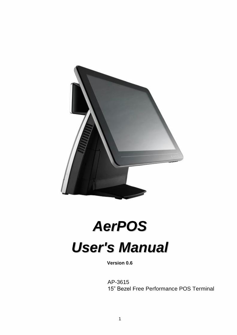
AAeerrPPOOSS
UUsseerr''ss MMaannuuaall Version 0.6
AP-3615
15” Bezel Free Performance POS Terminal

Copyright Notice This document is copyrighted, © 2012. All rights are reserved. Firich Enterprises Co., Ltd reserves the right to make improvements of the product described in this manual at any time without notice.
No part of this manual may be reproduced, copied, translated, or transmitted in any form or by any means without the prior written permission from Firich Enterprises Co., Ltd. Information provided in this manual is intended to be accurate and reliable. However, Firich Enterprises Co., Ltd assumes no responsibility for its use, nor for any infringements upon the rights of third parties, which may result from its use. The material in this document is for product information only and is subject to change without notice. While reasonable efforts have been made in the preparation of this document to assure its accuracy, Firich Enterprises Co., Ltd, assumes no liabilities resulting from errors or omissions in this document, or from the use of the information contained herein.
Record of Revision
Date Specs Ver. Description Note
V0.0 Initial
2012/09/02 V0.1 Initial Charles
V0.2
2012/12/13 V0.3 New Touch Utility Added
2nd
IO selection update
Vince
2013/05/11 V0.4 Remark COM3 simple com only has RX,TX
CashDrawer Provides Linux Sample code
Vince
2013/06/26 V0.5 FEC P-CAP Utility update Vince
2014/10/1 V0.6 Update External COM port pin define Vince

Safety and Warranty
1. Read these safety instructions carefully. 2. Keep this user's manual for later reference. 3. Disconnect this equipment from any AC outlet before cleaning. Do not use liquid or spray detergents for cleaning. Use a damp cloth. 4. For pluggable equipment, the power outlet must be installed near the equipment and must be easily accessible. 5. Keep this equipment away from humidity. 6. Put this equipment on a reliable surface during installation. Dropping it or letting it fall could cause damage. 7. The openings on the enclosure are for air convection. Protect the equipment from overheating. DO NOT COVER THE OPENINGS.
8. Make sure the voltage of the power source is correct before connecting the equipment to the power outlet. 9. Position the power cord so that people cannot step on it. Do not place anything over the power cord. 10. All cautions and warnings on the equipment should be noted. 11. If the equipment is not used for a long time, disconnect it from the power source to avoid damage by transient over-voltage. 12. Never pour any liquid into an opening. This could cause fire or electrical shock. 13. Never open the equipment. For safety reasons, only qualified service personnel should open the equipment. 14. If any of the following situations arises, get the equipment checked by service personnel: a. The power cord or plug is damaged. b. Liquid has penetrated into the equipment. c. The equipment has been exposed to moisture. d. The equipment does not work well, or you cannot get it to work according to the user’s manual. e. The equipment has been dropped and damaged. f. The equipment has obvious signs of breakage.
15. DO NOT LEAVE THIS EQUIPMENT IN AN UNCONTROLLED ENVIRONMENT WHERE THE STORAGE TEMPERATURE IS BELOW -20° C (-4°F) OR ABOVE 60° C (140° F). IT MAY DAMAGE THE EQUIPMENT.

TTaabbllee ooff CCoonntteenntt CChhaapptteerr 11 11
Introduction 1 AerPOS ( AP-3615 ) Introduction ......................................................................................... 1 A Quick Tour for AP-3615 .................................................................................................... 2
AP-3615 Dimension ...................................................................................................... 3 Rear I/O Panel Connectivity ................................................................................................. 4 Aer POS AP-3615 Packing List ............................................................................................ 5
CChhaapptteerr 22 66
Hardware Installation and Upgrading 6 2.5” Hard Disk Drive Installation ........................................................................................... 6 MSR / Finger Print Reciever / RFID / iButton Installation ..................................................... 7 MB / Heatsink & Smart Fan / Memory Installation ................................................................ 8 Memory (DDRIII RAM) & CPU Installation / MB Pin Define, Battery and Clear CMOS Setting ................................................................................................................................. 9 COM Port Power Setting .................................................................................................... 10 COM Port Pin Definition ..................................................................................................... 11 Integrated VFD / LCM Installation ...................................................................................... 12 15” / 11.6” 2nd Display Installation ...................................................................................... 13 15” 1st Touch Display Installation & Swapping.................................................................... 14 OSD Function and Adjustment ........................................................................................... 15 Cash Drawer Installation .................................................................................................... 16
CChhaapptteerr 33 1177
Software Installation and Setup 17 Chipset Driver Installation .................................................................................................. 18
Intel Chipset Installation Utilities for Windows XP ....................................................... 18 Intel Chipset Installation Utilities for Windows 7 .......................................................... 19
.Net Framwork 3.0 Tool Installation.................................................................................... 20 .Net Framework 3.0 Tool for Windows XP .................................................................. 20
VGA Driver Installation....................................................................................................... 22 VGA driver installation for Windows XP ...................................................................... 22 VGA driver installation for Windows 7 ......................................................................... 24
Intel Management Engine Components Driver Installation ................................................. 26 VGA driver installation for Windows 7 ......................................................................... 26
LAN Driver Installation ....................................................................................................... 28 Realtek RT8111E LAN Driver Installation for Windows XP ......................................... 28 Realtek RT8111E LAN Driver Installation for Windows 7 ............................................ 29
Audio Driver Installation ..................................................................................................... 30 Realtek ALC887 Audio Driver Installation for Windows XP & Windows 7 .................... 30
FEC Project – Capacitive Touch Utility (Raydium Controller) ............................................. 31 EETI TouchKit Tools Installation .......................................................... 錯誤! 尚未定義書籤。
EETI TouchKit Installation for Windows XP ................................... 錯誤! 尚未定義書籤。

EETI TouchKit Installation for Windows 7 ..................................... 錯誤! 尚未定義書籤。
TouchKit Control Panel ........................................................................ 錯誤! 尚未定義書籤。
Wireless LAN Driver Installation ......................................................................................... 55 Wireless LAN Driver Installation for all Windows Operating Systems (Optional) ......... 55
CChhaapptteerr 44 5566
Specifications 56 AP-3615 Specifications ...................................................................................................... 56
CChhaapptteerr 55 5577
Troubleshooting 57 Touch Panel Does Not Work ....................................................................................... 57 OSD Panel Cannot Work Precisely ............................................................................. 57 Cannot Detect SATA Storage HDD/SSD .................................................................... 57 LAN Is Not Functioning Properly ................................................................................. 58 COM1 ~ COM5 Are Not Functioning Properly ............................................................. 58 Cash Drawer Port Is Not Functioning Properly ............................................................ 58
Appendix A: 59
Smart Management Tool User Guide 59

AerPOS Series AP-3615
1
CChhaapptteerr 11
IInnttrroodduuccttiioonn
AerPOS ( AP-3615 ) Introduction
AerPOS is the perfect combination of reducing the Total Cost Ownership and enhanced quality requirement for POS system. With the design base on quality, space-effective and performance, its modularized design helps user no matter on the maintenance but the further upgrade in a very easy way. Main Features:
The high quality of resistive touch or durable tempered glass of projective capacitive
touch both are IP65 front panel compliant.
Desktop solution with high performance is perfect for heavy loading environment.
Mobile platform aims for green and energy saving requirement
Modularized design and easy maintenance for the key parts of its system , such as
storage device, CPU module and touch display.
With various devices support and sufficient I/O connectivity requirements.
Integrated VFD and the 2nd 15” / 11.6” LCD display.

AerPOS Series AP-3615
2
A Quick Tour for AP-3615
15” Touch Display
Power Switch HDD LED Smart Management Button
USB Port Display OSD
2.5” SATA Drive
Access
VFD / LCM MSR Finger Print Receiver RFID
i-Button
Cable Access
11.6” / 15” 2nd Display
Power Switch / Status Blue LED: Power ON
Red LED: Power Off / Standby
HDD / SATA Status
Orange LED: Operation
Validation Hole (Cool Air in)
Validation Hole
(Hot Air Out)
Smart Management
Connection button

AerPOS Series AP-3615
3
AP-3615 Dimension
D: 235mm W: 240mm
H: 360mm
W: 370mm
AerPOS Series AP-3615
4
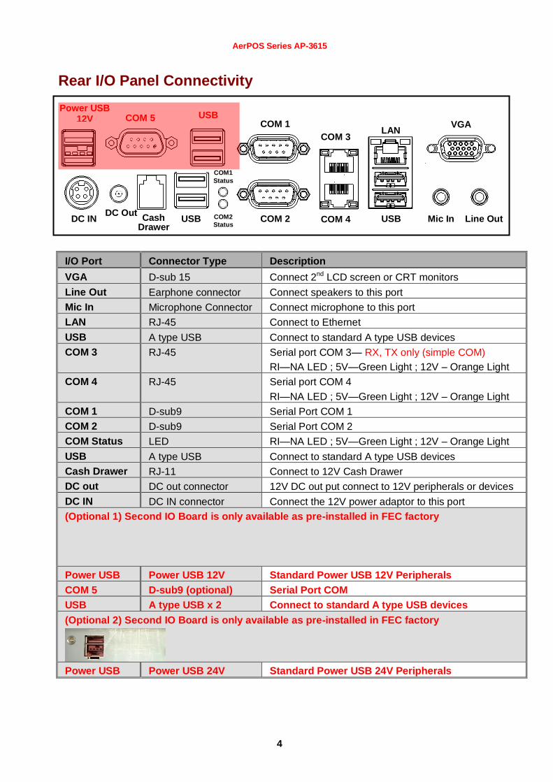
Rear I/O Panel Connectivity
I/O Port Connector Type Description
VGA D-sub 15 Connect 2nd LCD screen or CRT monitors
Line Out Earphone connector Connect speakers to this port
Mic In Microphone Connector Connect microphone to this port
LAN RJ-45 Connect to Ethernet
USB A type USB Connect to standard A type USB devices
COM 3 RJ-45 Serial port COM 3— RX, TX only (simple COM)
RI—NA LED ; 5V—Green Light ; 12V – Orange Light
COM 4 RJ-45 Serial port COM 4
RI—NA LED ; 5V—Green Light ; 12V – Orange Light
COM 1 D-sub9 Serial Port COM 1
COM 2 D-sub9 Serial Port COM 2
COM Status LED RI—NA LED ; 5V—Green Light ; 12V – Orange Light
USB A type USB Connect to standard A type USB devices
Cash Drawer RJ-11 Connect to 12V Cash Drawer
DC out DC out connector 12V DC out put connect to 12V peripherals or devices
DC IN DC IN connector Connect the 12V power adaptor to this port
(Optional 1) Second IO Board is only available as pre-installed in FEC factory
Power USB Power USB 12V Standard Power USB 12V Peripherals
COM 5 D-sub9 (optional) Serial Port COM
USB A type USB x 2 Connect to standard A type USB devices
(Optional 2) Second IO Board is only available as pre-installed in FEC factory
Power USB Power USB 24V Standard Power USB 24V Peripherals
COM 1
COM 2
COM 3
COM 4
LAN
USB
VGA
USB Cash Drawer
DC Out Mic In Line Out DC IN COM2
Status
COM1
Status
COM 5 USB Power USB
12V

AerPOS Series AP-3615
5
Before you unplug the power USB cable from I/O panel, please ensure unplug the A/C Cord in
advanced.
Aer POS AP-3615 Packing List
Standard Optional & Peripherals
1 15” AP-3615 AerPOS Touch Terminal 1 Optional IO Board
2 12V 150W Power Adaptor 2 RJ-45 to D-sub9 Convert Cable
3 AC Power Cable 3 MSR / RFID / Finger Print Receiver / I-Button
4 20x2 VFD / 20x2 LCM / 240x64 LCM
5 15” / 11.6” 2nd
Display Bracket
6 Wireless Lan Module

AerPOS Series AP-3615
6
CChhaapptteerr 22
HHaarrddwwaarree IInnssttaallllaattiioonn aanndd UUppggrraaddiinngg
2.5” Hard Disk Drive Installation
1. Turn off power and remove power cord from the terminal
2. Unscrew the maintenance door at the front side of the terminal body
3. Flip the maintenance door and Extract 2.5” SATA storage bracket out
(no cable connected)
4. Place storage driver on the bracket and fasten it with 4 screws.
5. Restore the maintenance door to the system.
6. Fix the maintenance door with a screw.
7. Connect power cord to the system.
Do not remove the Display Module without switch off the terminal. Power must be switched off and power cord must be unplugged. Every
time you service the system, please be aware of this.

AerPOS Series AP-3615
7
MSR / Finger Print Reciever / RFID / iButton Installation
1. Remove the plastic cover at the back of Touch Display Module
2. Insert the MSR / RFID / Finger Print Receiver / I-button Module into USB A-Type Connector. Fix the Touch Display Module with one screw.
3. Make sure the USB connected and screw is fastened well.
4. If you are looking for the detail Utility of MCR, Finger Print Reader, I-button Reader, RFID Reader, please contact FEC’s FAE.(Please refer to FEC website for more information, http://www.fecpos.com )
AerPOS Series AP-3615
8
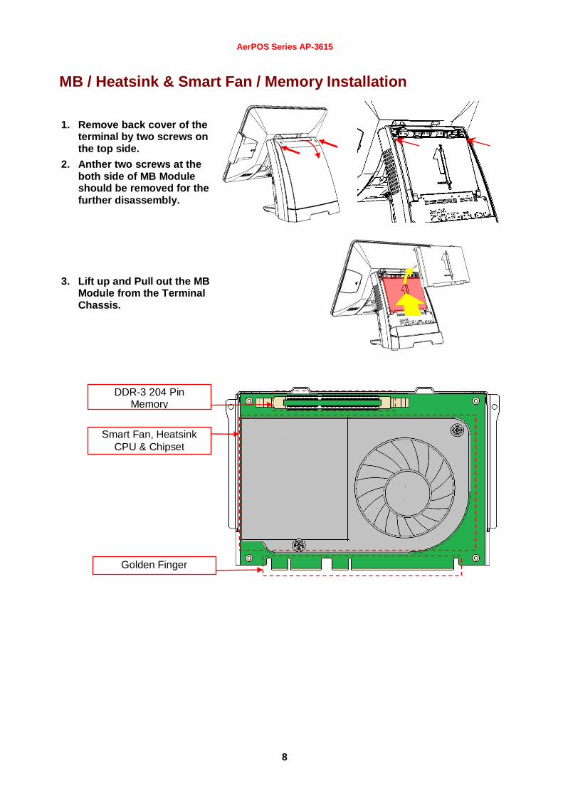
MB / Heatsink & Smart Fan / Memory Installation
1. Remove back cover of the terminal by two screws on the top side.
2. Anther two screws at the both side of MB Module should be removed for the further disassembly.
3. Lift up and Pull out the MB Module from the Terminal Chassis.
DDR-3 204 Pin Memory
Smart Fan, Heatsink
CPU & Chipset
Golden Finger

AerPOS Series AP-3615
9
4. During the MB installation, Please Make sure the MB Golden finger is well connected with IO Board Slot.
Memory (DDRIII RAM) & CPU Installation / MB Pin Define, Battery and Clear CMOS Setting
1. Disassembly the MB Module, then Memory installation can be done from the top side of MB Module. CPU installation has to remove Thermal Fan Module by 2 screws, after the CPU installation, please ensure the thermal pads between CPU, chipset and heatsink are well contacted.
2. According to the MB on-board connectors or golden finger pin define and Battery Setting, CMOS Clear, please refer to the FH-H611 MB Manual. (Will update soon)
DDR-3 204Pin Memory Slot
Smart Fan Heatsink
CPU & Chipset

AerPOS Series AP-3615
10
COM Port Power Setting
AP-3615 COM Port Power can adjust via BIOS or Smart Management Tool.
5. COM Port Power Configuration:
6. Advance > Super IO Configuration > Serial Port 1 or 2 Configuration
Advance > F81214 Super IO Configuration > Serial Port 3 or 4 Configuration
7. COM 1 or 2 or 3 or 4 Port Power > Enable
COM 1 or 2 or 3 or 4 Power Type > +5V or +12V (select the proper power output for proper com port devices)
If you need more information about the BIOS setting or Smart Management Setting, please refer to the MB Manual or Smart Management Manual or contact FEC’s FAE.

AerPOS Series AP-3615
11
COM Port Pin Definition
COM 1, 2, 5 D-sub9 Pin Define
Pin No. Signal Description
1 DCD
2 RXD
3 TXD
4 DTR
5 Ground
6 DSR
7 RTS
8 CTS
9 RI / 5V / 12V
COM 3 RJ-45 Pin Define
Pin No. Signal Description
1 RI / 5V / 12V
2 NC
3 Ground
4 NC
5 NC
6 NC
7 TXD
8 RXD
COM 4 RJ-45 Pin Define
Pin No. Signal Description
1 RI / 5V / 12V
2 CTS
3 Ground
4 RTS
5 DTR
6 DSR
7 TXD
8 RXD
COM 1
COM 2
COM 3
COM 4
LAN
USB
VGA
USB Cash Drawer
DC Out Mic In Line Out DC IN COM2
Status
COM1
Status
COM 5 USB Power USB
12V

AerPOS Series AP-3615
12
Integrated VFD / LCM Installation
1. Remove the VFD Plastic cover from the terminal
2. Connect the COM 3 internal cable between Terminal and VFD / LCM Module and install the VFD/ LCM module with Terminal. Fasten one screw back and make sure VFD/LCM module is fixed.
3. VFD is connected to the COM3 (COM3 has internal power which has been pre-set as 12V power)
** Please note When VFD/LCM is integrated, please remove the device which connects to the external COM3 on Rear IO panel to prevent I/O interrupt.
4. Adjust the VFD / LCM angle into proper position.

AerPOS Series AP-3615
13
15” / 11.6” 2nd Display Installation
1. Remove the VFD plastic cover
2. Assemble the 2nd screen with bracket with 4 screws
3. Assemble the 2nd Screen with bracket to Terminal.
4. Fasten 3 screws
(1 on top, 2 underneath)

AerPOS Series AP-3615
14
5. Connect the monitor to AP-3615 by VGA & DC cable
15” 1st Touch Display Installation & Swapping
1. Release 1 thumb screw at the back side of Display
2. Lift the Display Module up to disassemble from the main unit of terminal
3. Display and main body units are separated.

AerPOS Series AP-3615
15
4. Reverse the process can assembly back the Touch Display Module.
** please make sure the touch display module is firmly connected to the docking slot **
**Note**
During the process of disassembly and installation, please ensure the terminal is “Power Off” and remove AC cord. “Hot Swap” could casue the internal protection to block touch display functionality.
OSD Function and Adjustment
OSD function and adjustment
Back Light Power (finger touch for 5 seconds) Back Light Power On – Blue LED indication Back Light Power Off – Red LED indication
P-CAP Touch re-calibrates during Power Off and On
Button Down (finger touch for 2 seconds)
Back Light Dimmer Down
Button Up (finger touch for 2 seconds)
Back Light Dimmer Up
No Function / Reserve Function for AerTouch Monitor

AerPOS Series AP-3615
16
Cash Drawer Installation
Before connecting the cash drawer to the AP-3615, please make sure the drive voltage and cable pin assignment of the cash drawer matches the definition of the cash drawer port of AP-3615.
Note: If the cash drawer cannot be detected by the system, please refer to trouble shooting.
Up to two cash drawers may be driven from this port. Driving voltage of the solenoid is DC+12V. I/O port 284 is used for drawer operation. A test program is supplied, for Linux and Windows, sample code of which is available on request by software developers.
Value Description
Byte 1 (0xA0) 0x00 GPIO / 0x01 or DIO / 0x00.
Byte 2-3 (0xA1 ~ 0xA2) 0xA07 Output address.
Byte 4-5 (0xA3 ~ 0xA4) 0xA07 Inpute address.
Byte 6 (0xA5) 0xFD Open cashdrawer1 value.
Byte 7 (0xA6) 0xFB Open cashdrawer2 value.
Byte 8 (0xA7) 0xFF Close cashdrawer value.
Byte 9 (0xA8) 0x01 Cashdrawer status mask.
Cash_Drawer1: DIO with RJ-11 Connector PIN No. Signal Description
1 Ground
2 DIO Out 1
3 +12V / + 24V
4 DIO IN 0
5 DIO Out 0
6 Ground
COM 1
COM 2
COM 3
COM 4
LAN
USB
VGA
USB Cash Drawer
DC Out Mic In Line Out DC IN COM2
Status
COM1 Status
COM 5 USB Power USB
12V
Pin1

AerPOS Series AP-3615
17
CChhaapptteerr 33
SSooffttwwaarree IInnssttaallllaattiioonn aanndd SSeettuupp
AP-3615 comes with a variety of drivers for different operating systems.
You can download all the necessary drivers and utilities from http://www.fecpos.com.
Or send an e-mail to the Customer Service Department of FEC for further assistance.
AerPOS Series AP-3615
18
Chipset Driver Installation
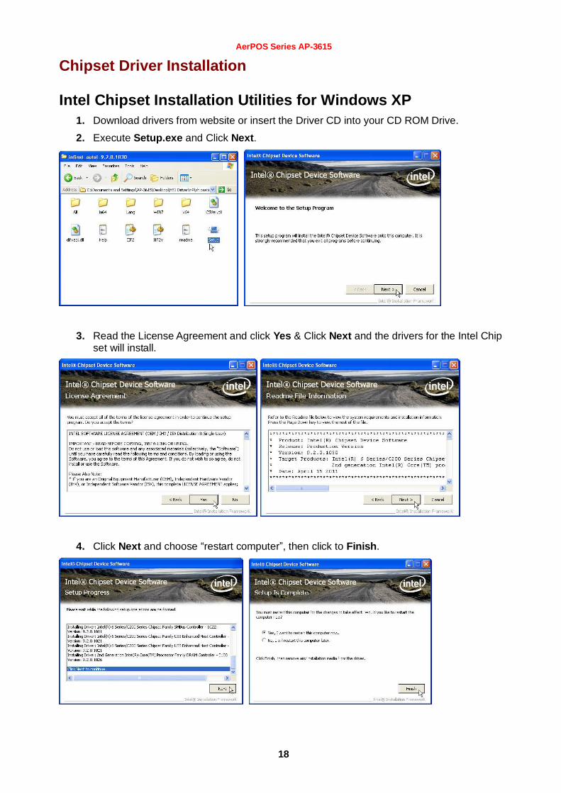
Intel Chipset Installation Utilities for Windows XP
1. Download drivers from website or insert the Driver CD into your CD ROM Drive.
2. Execute Setup.exe and Click Next.
3. Read the License Agreement and click Yes & Click Next and the drivers for the Intel Chip set will install.
4. Click Next and choose “restart computer”, then click to Finish.

AerPOS Series AP-3615
19
Intel Chipset Installation Utilities for Windows 7
1. Download drivers from website or insert the Driver CD into your CD ROM Drive.
2. Execute Setup.exe and Click Next.
3. Read the License Agreement and click Yes & Click Next and the drivers for the Intel Chip set will install.
4. Click Next and choose restart computer for finishing the Chipset Driver, click to Finish.

AerPOS Series AP-3615
20
.Net Framwork 3.0 Tool Installation
.Net Framework 3.0 Tool for Windows XP 1. Download drivers from FEC website or insert the Driver CD into your CD ROM Drive.
2. Double click Setup.exe, and Click Next to start tool installation
3. Execute dontnetfx3 for further setup

AerPOS Series AP-3615
21
4. choose I have read and ACCEPT the terms of the license Agreement and click Install for
the following steps
5. Click the message pop out to check for the detail process. Finally, click Exit to finish the
installation.

AerPOS Series AP-3615
22
VGA Driver Installation
VGA driver installation for Windows XP 1. Download drivers from website or insert the CD into your CD ROM Drive.
2. Execute Steup.exe
3. Select Next and click Yes of License Agreement Page.
4. Select Next to continue driver installation.

AerPOS Series AP-3615
23
5. Finally, Finish and Restart the system

AerPOS Series AP-3615
24
VGA driver installation for Windows 7 1. Download drivers from website or insert the CD into your CD ROM Drive.
2. Execute Steup.exe and select Next
3. Click Yes of License Agreement Page.
4. Select Next to continue driver installation.

AerPOS Series AP-3615
25
5. Finally, Finish and Restart the system

AerPOS Series AP-3615
26
Intel Management Engine Components Driver Installation
VGA driver installation for Windows 7 1. Download drivers from website or insert the CD into your CD ROM Drive.
2. Execute Steup.exe
3. Select Next and click Yes of License Agreement Page.
4. Select Next to continue driver installation.

AerPOS Series AP-3615
27
5. Finally, Finish and Restart the system

AerPOS Series AP-3615
28
LAN Driver Installation
Realtek RT8111E LAN Driver Installation for Windows XP 1. Download drivers from website or insert the CD into your CD ROM Drive.
2. Execute Setup.exe.
3. Click Next to continue
4. Click Finish to complete the installation procedure.

AerPOS Series AP-3615
29
Realtek RT8111E LAN Driver Installation for Windows 7 1. Download drivers from website or insert the CD into your CD ROM Drive.
2. Execute Setup.exe.
3. Click Next to continue and Finish to complete the installation procedure.
AerPOS Series AP-3615
30
Audio Driver Installation
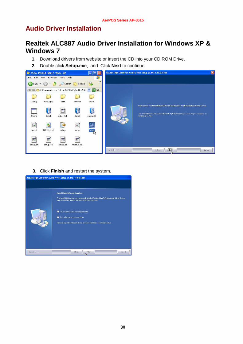
Realtek ALC887 Audio Driver Installation for Windows XP & Windows 7
1. Download drivers from website or insert the CD into your CD ROM Drive.
2. Double click Setup.exe, and Click Next to continue
3. Click Finish and restart the system.

AerPOS Series AP-3615
31
FEC Project – Capacitive Touch Utility (Raydium Controller)
FEC Projective – Capacitive Touch Utility Introduces:
1. Activate Calibration
2. Mode of FEC Capacitive Touch Panel and default settings
3. Capacitive Touch User Configuration
4. F/W Reading or F/W Update
5. Touch Function for Second Screen
Activate Calibration
There are two different methods to do the calibration: (1) OSD on/off, (2) Utility Calibration
1. OSD on/off
The FEC P-CAP touch is Auto Calibrating during the Terminal boots up or power on the
display. Please note: during the process of touch auto calibration, keeps finger touches or other metal parts from the
touch panel for 10 seconds until the calibration is finished.
2. Utility Calibration
“RADPara_20130417” Utility is able to run within windows XP and windows 7 OS environment
1. Execute Touch Utility “RADPara_20130417”
2. Click “Auto Detect” wait for 10 sec for connection between Touch Utility and Touch
Controller, until Touch or Mouse Mode shown.
3. Click “General” and press Calibration.
Please note: during the process of touch auto calibration, keeps finger touches or other metal parts from the touch panel for
10 seconds until the calibration is finished.

AerPOS Series AP-3615
32
Utility Install
1. Open Folder (eGalaxTouch_5.13.0.12706-Release-140506-ForPCAP)
2. Double click at the setup.exe file to start software driver installation. Then, the setup
program will guide user to complete software installation.

AerPOS Series AP-3615
33
3. Click “Yes”
4. Press Next button to continue installation, then, a new dialog popped up as below,
5. Select “I accept the terms of the license agreement” And “Next”

AerPOS Series AP-3615
34
6. This dialog shows to ask user if the RS-232 driver for touch screen to be installed. User can check this
check for RS-232 driver installation. After check or uncheck this check box, press Next button to
continue installation. Then, it shows new dialog as below,
7. User to make sure that the eGalaxTouch USB controller devices were well connected with system USB
ports to guarantee the USB eGalaxTouch device drivers updated after driver installation. Then, just press OK to continue, eGalaxTouch driver package supports multiple monitor operation. If your application is for multiple monitors system, please check the check box to support multiple monitors. So that, the a multiple monitor setting property page will be shown in eGalaxTouch utility. Then, press Next to continue.

AerPOS Series AP-3615
35
8. A pop up window for user to choose the target path the files will be copied to. Then, Press Next to
continue,
9. A dialog popped up for user to assign the target program folder. Press Next
AerPOS Series AP-3615
36
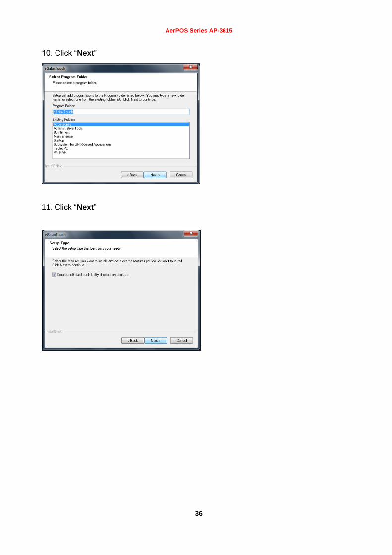
10. Click “Next”
11. Click “Next”

AerPOS Series AP-3615
37
12. Click “Next”
13. Check “Installed Touchscreen Controllers”

AerPOS Series AP-3615
38
Utility User Guide
General Property Page
The general property page in eGalaxTouch utility shows all of eGalaxTouch touchscreen controllers
installed as below, including RS232, USB and PS2 interfaces.
User can select the controller list in the window to do configuration for it. When user use a mouse or other
input device to select the controller device in the controller list window, The controller name will be shown in
the title bar of the main window( the property sheet ). Also, all of the other property pages will be updated
for this selected controller. In some application, user may in place edit and change the controller name for
easy identification.

AerPOS Series AP-3615
39
In addition, there are 3 function push buttons in this property page. 1.1 Add
The function button is used for serial RS232 controllers only. Press this button to search the eGalaxTouch serial controllers connected with the system COM ports. Whenever it finds a new eGalaxTouch serial controller, a new serial controller icon object will be shown in the controller list window automatically. USB eGalaxTouch device supports plug and play, the icon object for USB controller will be shown in the controller list window automatically when the USB controller is connected with the system USB port. And, the icon object for the USB controller will disappear automatically as soon as the device was removed from the system USB port. eGalaxTouch PS2 driver support PS2 mice and eGalaxTouch touchscreen controller. It can works with both PS2 mice and eGalaxTouch touchscreen PS2 controller. After the eGalaxTouch PS2 driver was installed, this utility assumes the PS2 touchscreen controller exists and is always shown in the controller list window.
1.2 Remove This function button is used for serial RS232 controllers only. This button will be greyed and disabled automatically when the selected controller in the controller list window is not RS232 type. Press to remove and uninstall the selected serial RS232 controller from the system. Then, this serial RS232 icon object in controller list window disappears automatically. USB eGalaxTouch device supports plug and play, the icon object for USB controller will be shown in the controller list window automatically when the USB controller is connected with the system USB port. And, the icon object for the USB controller will disappear automatically as soon as the device was removed from the system USB port. eGalaxTouch utility does not allow user to remove/uninstall the PS2 device driver dynamically. To uninstall the eGalaxTouch PS2 driver, user needs to go to Windows® Device Manager to do un-installation. In addition, after PS2 un-installation, it needs to system reboot to complete un-installation.
1.3 Monitor Mapping
eGalaxTouch driver utility supports multiple monitor and display system. This function will help user to does monitor mapping. a new window will be popped-up on a monitor as below. Please touch the touchscreen panel to do mapping. In addition , please do calibration after finish monitor mapping.

AerPOS Series AP-3615
40
Setting Property Page The Setting property page can be shown in eGalaxTouch Utility as below,
There are function buttons and check boxes described as below
1. Beep 1-1 ) Beep On Touch
Check this check box to enable driver to generate a beep sound when touch touchscreen state is switched from untouched to touched state.
1-2 ) Beep On Release Check this check box to enable driver to generate a beep sound when touchecreen state is switched from touched state to untouch state.
1-3) Beep From System Beep Check this check box to make the beep from system speaker.
1-4) Beep From Sound Card Check this check box to make the beep from sound card. 1-5) Frequency
Adjust this frequency to control the beep sound frequency generated by the driver. 1-6) Duration
Adjust this duration to control the beep sound duration.
2 Linearization Style eGalaxTouch utility provides user with both 9 points and 25 points calibration for linearization. User can select the suitable kind of linearization type.
3 Double Click Time The double Click Time group is used to set system double click time. Change this value will affects the double click behavior for all of the mice devices in the system. Two continuous clicks at the same area within this specified time period will be recognized as a double click event.
4 Double Click Area The double click area group is used to set the system double click area. Change this value will affects the double click behavior for all of the mice devices in the system. Two continuous click with this specified area in the specified double click time will be recognized as a double click event.
5 Mouse Emulation mode There are 5 mouse emulation modes for eGalaxTouch touchscreen controllers. Press on the button to change the emulation mode,
4-1) Normal Mode

AerPOS Series AP-3615
41
Normal mode behaves mouse button down and mouse move. User can select this mode to select object, and dragging the object.
4-2) Click On Touch With this Click On Touch mode, the driver emulates a mouse click event when the touchscreen state was switched from un-touched state to touched state. Then, the driver always generate mouse move event and is tracking the touch position until the touchscreen state switched to un-touch state.
4-3) Click On Release With this Click On Release mode, the driver emulates a mouse click event when the touchscreen state was switched from touched state to un-touched state.
4-4) Click On Touch without moving cursor With this mode, the driver behaves similar as Click On Touch mode. The cursor does not move to the touch position except the first touch point.
4-4) Click On Release without moving cursor With this mode, the driver behaves similar as Click On Release mode. The cursor does not move to the touch position except the lift-off point.
4-5) Desktop Mode With this mode, the driver behaves similar as Normal Mode. But the driver will not report mouse button down immediately after user touches down. User needs to touch and stay at one point for a few milli-second, then the driver will report mouse touch down.

AerPOS Series AP-3615
42
6 Option
The advanced functions are
5-1) Enable Constant Touch( Hold ) Constant Touch is the function to check if the most recent touched position is same
as the previous touched point. If the points difference is smaller than the defined area, the driver does not generate any mouse event to reduce system loading.
Check this check box to enable this function ( Hold ) and un-check it to disable this function.
5-2) Enable Auto Right Click If the touchscreen was kept touched for a specified time, the driver will generate a mouse right button click event if this function was enabled. Check the check box to enable this function and uncheck it to disable this function.
5-3) Enable Touch The driver read the data input from controller to generate mouse event. However, it can be enabled or disabled to generate the mouse event. Check this check box to make driver to generate the mouse event when it receives the touch point input from eGalaxTouch touchscreen control and un-check it to stop driver generating the mouse event.
5-4) Enable cursor stabilization A software filter was implemented inside the driver to filter some noise to stabilize and smooth the touch points. Then, the user can see a more stable cursor. Check this check box to enable this software filter and un-check it to disable this function.
5-5) Constant Touch Area ( Hold area ) Adjust the parameter for Constant Touch( Hold ) function. This is a criterion to judge if the most recent touched point is same as the previous touched point. If the points difference is within this area, it will be recognized as the same touch point and the driver does not generate new mouse event for this new touch point.
5-6) Auto Right Click Time Adjust the Right click time for auto right click function. If the touchscreen was touched and hold for this period of time, the driver generates a mouse right click event.

AerPOS Series AP-3615
43
Tool Property Page Calibration, draw test tools and the linearity curve of the touchscreen were list in this property page shown as below for user to do touchscreen calibration and touch position test.
User can do calibration or draw test by pressing the function push buttons. 1. Linearization Curve
Linearization curve of the touchscreen is list in this page for reference and trouble shooting purpose. 2. 4 points calibration
It needs calibration before the touchscreen can work accurately. Whenever the user feel the accuracy lost, user can do calibration again to get a more accuracy touch function. Pressing this button, a new window will be popped-up at the location when the touchscreen was mapped to area for this touch system to guide the user do 4 points calibration. User should follows the guide to touch and hold the blinking symbol in the calibration window until it shows “OK” to make sure that the utility can gather enough data for computation.
3. Clear and Calibration Press this button to erase the 25 points calibration/linearization parameters and force user to do 4 points calibration again. After 25 points calibration data was clear, the 4 points calibration data will be invalid. It needs to do 4 points calibration.
4. Linearization Linearization ( 25 or 9 points calibration ) function is used to compensate the touchscreen linearity. After linearization completed, the linearity of the touchscreen will be shown in the Linearity curve window. Pressing this button, a new window will be popped-up at the location when the touchscreen was mapped to area for this touch system to guide the user do 25 points calibration. User should follows the guide to touch and hold the blinking symbol in the calibration window until it shows “OK” to make sure that the utility can gather enough data for computation.

AerPOS Series AP-3615
44
5. Draw Test This function is used for accuracy and performance check. Press this button and a new pop up window will be popped up in the location where the touchscreen was mapped to the touch system as below,
User can press the Clear button to clear the window. Press Quit button to terminate this draw test.

AerPOS Series AP-3615
45
Monitor Property Page eGalaxTouch driver utility supports multiple monitor and display system. To work with multiple monitor system, user needs to do configuration and map the touchscreen working area to the system display area correctly. User can do such configuration with the property page shown as below,
Display The system monitor display geometry is shown in the Monitors window in this page to show the locations of all of the monitors of the system.
Users can follow below instructions to do the configuration
1. Enable multiple monitor Check this check box to enable multiple monitor support and uncheck it to disable multiple monitor support. When this function is disabled, the touchscreen will be mapped to the primary monitor automatically. When this function is enabled, user can double click on the monitor area in the monitor geometry window to assign the monitor area where the touchscreen will be mapped. In other words, the touchscreen will work with the selected monitor. Then, the selected monitor area rectangle line will be changed to white and the other monitor rectangles line will be grey.
2. Map to main monitor when the system has only one monitor
When the multiple monitor function was enabled, and the system has only one monitor, Driver allows user to generate the mouse event for the primary monitor or not when the touchscreen is not mapped to the primary monitor. Check the check box to enable this function, then, the driver will generate the mouse event for the primary monitor even though the touchscreen is configured as other monitor mapping and multiple monitor function is enabled.
3. Operation Mode
eGalaxTouch driver supports split display mode for those applications which do not map the touchscreen to the full screen of the monitor. 3-1) Full screen The touchscreen will be mapped to the full screen of the specified monitor. 3-2) Right screen The touchscreen will be mapped to the half right screen of the specified monitor. 3-3) Left screen The touchscreen will be mapped to the half left screen of the specified monitor.

AerPOS Series AP-3615
46
3-4) Upper screen The touchscreen will be mapped to the upper half screen of the specified monitor. 3-5) Lower screen The touchscreen will be mapped to the lower half screen of the specified monitor. 3-6) Other operation mode 3-6-1) Quarter 1
The touchscreen will be mapped to the first quarter area of the specified monitor display. 3-6-2) Quarter 2
The touchscreen will be mapped to the 2nd
quarter area of the specified monitor display. 3-6-3) Quarter 3
The touchscreen will be mapped to the 3rd
quarter area of the specified monitor display. 3-6-4) Quarter 4
The touchscreen will be mapped to the 4th quarter area of the specified monitor display.
3-6-5) Customized User can type in the range (Left, Right, Top, Bottom) to customize the working area. With this mode, the driver does not correct the mapping area when the display resolution changed. It needs to do configuration setting again whenever the display resolution changed.
User can also customize the working area with “Drag Working Area” function.

AerPOS Series AP-3615
47
Click the “Drag Working Area” button, the image will switch back to the desk top, then user can customize
the working area by drawing and dragging the rectangle. Then click “confirm” to set the working area. Or
“Quit” to cancel.
3-7) Active Area If several areas but not the full screen are needed as working area, eGalaxTouch allows user to customize up to 6 active areas, only in which touches will be recognized. Go to “Active Area” Tab first, user can type in the range of the preferred active areas or customize the active areas by using “Dray Active Area” function. Check the box for “Enable The Active Area Function”

AerPOS Series AP-3615
48
If user prefer to type in the range of the active area, please use the scroll bar to number and choose the active areas. If user prefer to use “Drag Active Area” function, please click on the “Drag Active Area” button. The image will switch to desk top, and there are six box in different colors numbered from 1~6.
When a box is touched (or clicked), user can draw/drag a rectangle as the customized active area.

AerPOS Series AP-3615
49
When another box is touched, user can draw/drag another rectangle as another active area.
User can use this function to customize six active areas, these areas can be overlapped.

AerPOS Series AP-3615
50
If user wishes to cancel a particular active area, simply click on the box on the left hand side, and click
“Clear”.
For example, Area 1 is now cleared. Once everything is done, click “Confirm”. User can “Quit” anytime during customizing the active areas.

AerPOS Series AP-3615
51
Edge Compensation Property Page For some special touchscreen which can not reach to the edge area of the full screen, eGalaxTouch utility provides user with edge compensation tool to solve such problem and make it easy to touch the edge area without accuracy lost. Stretch a little bit near the edge area.
User can set the stretch percentage for the 4 edges. In addition, it allows user to set an offset for the touch point for special application.

AerPOS Series AP-3615
52
Hardware Property Page This hardware property page shows the model and firmware version of the eGalaxTouch touchscreen controller. The software will query the hardware information from controller and show the information as below.

AerPOS Series AP-3615
53
About Property Page “About” shows some information for eGalaxTouch driver information. User can click Download to download the latest driver from web site.

AerPOS Series AP-3615
54

AerPOS Series AP-3435
55
Wireless LAN Driver Installation
Wireless LAN Driver Installation for all Windows Operating Systems (Optional)
1. Download drivers from website or insert the CD into your CD ROM Drive.
2. Run Setup.EXE
3. Click Next
4. Click Next
AerPOS Series AP-3615
56
CChhaapptteerr 44
SSppeecciiffiiccaattiioonnss
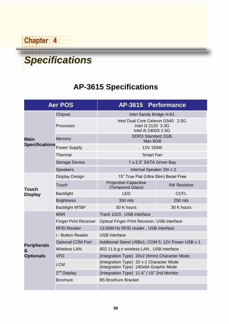
AP-3615 Specifications
Aer POS AP-3615 Performance
Main Specifications
Chipset Intel Sandy Bridge H-61
Processor Intel Dual Core Celeron G540 2.5G
Intel i3 2120 3.3G Intel i5 2400S 2.5G
Memory DDR3 Standard 2GB,
Max 8GB
Power Supply 12V 150W
Thermal Smart Fan
Storage Device 1 x 2.5” SATA Driver Bay
Speakers Internal Speaker 2W x 2
Touch Display
Display Design 15” True Flat (Ultra Slim) Bezel Free
Touch Projective-Capacitive
(Tempered Glass) 5W Resistive
Backlight LED CCFL
Brightness 350 nits 250 nits
Backlight MTBF 50 K hours 30 K hours
Peripherals & Optionals
MSR Track 1/2/3 , USB interface
Finger Print Receiver Optical Finger Print Receiver, USB interface
RFID Reader 13.56M Hz RFID reader , USB interface
I - Button Reader USB interface
Optional COM Port Additional Stand USBx1; COM 5; 12V Power USB x 1
Wireless LAN 802.11.b.g.n wireless LAN , USB interface
VFD (Integration Type) 20x2 (9mm) Character Mode
LCM (Integration Type) 20 x 2 Character Mode (Integration Type) 240x64 Graphic Mode
2nd Display (Integration Type) 11.6” / 15” 2nd Monitor
Brochure B5 Brochure Bracket
AerPOS Series AP-3615
57
CChhaapptteerr 55
TTrroouubblleesshhoooottiinngg
Please note that the following troubleshooting guide is designed for engineer who has strong computer hardware knowledge or Engineers and Maintenance.
Touch Panel Does Not Work
A) Check “Touch Display Module” is connected well with terminal.
B) Check HID USB touch device is detected by OS.
C) (Resistive Touch) Check if the EETI driver or the TouchKit driver has been properly
installed. Or try to re-install again (Please refer to the EETI driver and touch kit installation).
D) (Capacitive Touch) Check if the FEC-AUO Capacitive touch is automatically detected by
Windows 7, or properly installed the touch driver in Windows XP.
E) (Capacitive Touch) Please do not keep the capacitive touch in high humidity and condensing environment, such as out door or bathroom, where might affect the touch performance or might need to be calibrate more frequently.
F) Check if the cable connects well between touch panels and touch controller
G) (Capacitive Touch Calibration) Reboot the system, and the Capacitive Touch can be calibrated automatically.
OSD Panel Cannot Work Precisely
A) Please touch each single OSD button for more than two seconds in order to trigger the function.
B) Make sure the finger is not touching more than one button each time.
Cannot Detect SATA Storage HDD/SSD
A) Make sure storage device is well connected in the SATA Connector.
B) HDD FFC cable is not connected properly to the main board or it could be defective.
C) Check CMOS setup, set SATA HDD to Auto Detect.
D) On-board SATA port could be defective.

AerPOS Series AP-3615
58
LAN Is Not Functioning Properly
A) Check if the LAN driver is installed properly.
B) Check if there are any IRQ conflicts.
C) Check if the RJ45 cable is properly connected.
D) The on-board LAN chip could be defective.
COM1 ~ COM5 Are Not Functioning Properly
A) Check if the I/O ports are enabled in the CMOS setup.
B) Check if there are any IRQ conflicts.
C) The main board or I/O board could be defective.
D) (Reminder) The COM3 is shared by the read I/O and VFD, if you connector the VFD, please remove the device which is connected with external COM3.
Cash Drawer Port Is Not Functioning Properly
A) Make sure the pin assignment matches between the cash drawer and the RJ11 cash drawer port.
B) Verify if the digit I/O port address and bit are correct.
C) The main board could be defective.

AerPOS Series AP-3615
59
AAppppeennddiixx AA::
SSmmaarrtt MMaannaaggeemmeenntt TTooooll UUsseerr GGuuiiddee
Smart Management Tool is FEC latest hardware management engine built in AerPOS &
BP-500. With this tool, user could easily access the data inside the system that could
user to identify the status and error during operation.
1. Move this Smart Management.exe to Desktop or any preferred location in your system
(Windows XP & Windows 7 only)
2. Double click the .exe file to activate Smart Management as the following picture.
3. Press the Smart Management button aside the AP-3615 for 5 seconds to enter the
Terminal Status. (This button is just above the external USB connector, Please make
sure you did not press the Power Button or HDD LED)

AerPOS Series AP-3615
60
Please refer to the following definition table for the information showed on the Terminal
Status
Item Description
MB Version Shows the M/B version
BIOS Version Shows the BIOS version of the M/B
IO Version Shows the firmware version on the I/O board
Display Version Shows the firmware version on the Display board (AerPOS
only)
Operation Service
Hours
Shows the time this system has been powered up
Stand-by Service
Hours
Shows the time this system has been connected to A/C input
Abnormal On/Off
Count
Shows the times this system has been force disconnect with
A/C input
ON/OFF Total Shows the times this system has been power on & off
normally
System Operation
Hours
Shows the latest time the system has been operated
Display Module Plug in
Time
Shows the times the display module has been re-plugged
(AerPOS only)
Total Display Module
Standby Hours
Show the time the display module has been connected with
the system & the system has been connected to A/C input
(AerPOS only)
Total Back Light Hour Show the time the backlight has been used (AerPOS only)
Each data would be recorded after the system is shutdown normally, for any incorrect
operation or force shutdown, only Abnormal On/Off Count & ON/OFF Total will be
recorded, the rest data will missed.
4. User could monitor the Thermal & Fan Status inside the system by clicking the icon
Thermal.
AerPOS Series AP-3615
61
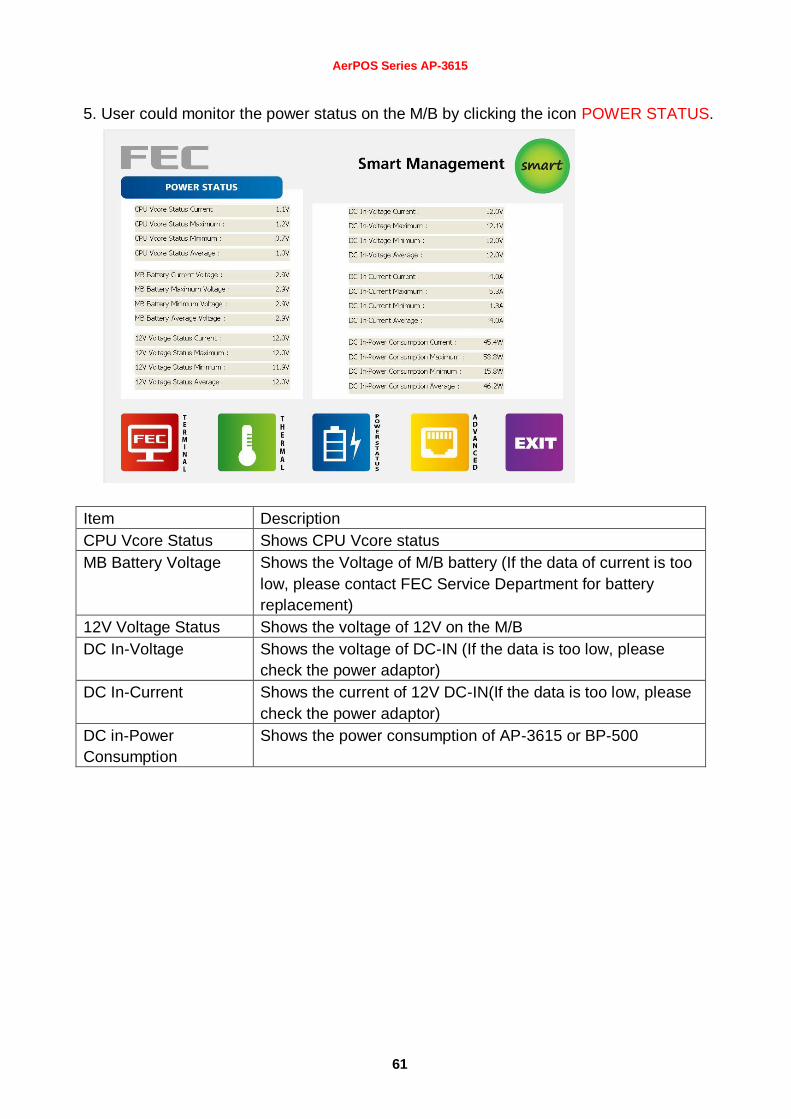
5. User could monitor the power status on the M/B by clicking the icon POWER STATUS.
Item Description
CPU Vcore Status Shows CPU Vcore status
MB Battery Voltage Shows the Voltage of M/B battery (If the data of current is too
low, please contact FEC Service Department for battery
replacement)
12V Voltage Status Shows the voltage of 12V on the M/B
DC In-Voltage Shows the voltage of DC-IN (If the data is too low, please
check the power adaptor)
DC In-Current Shows the current of 12V DC-IN(If the data is too low, please
check the power adaptor)
DC in-Power
Consumption
Shows the power consumption of AP-3615 or BP-500
AerPOS Series AP-3615
62
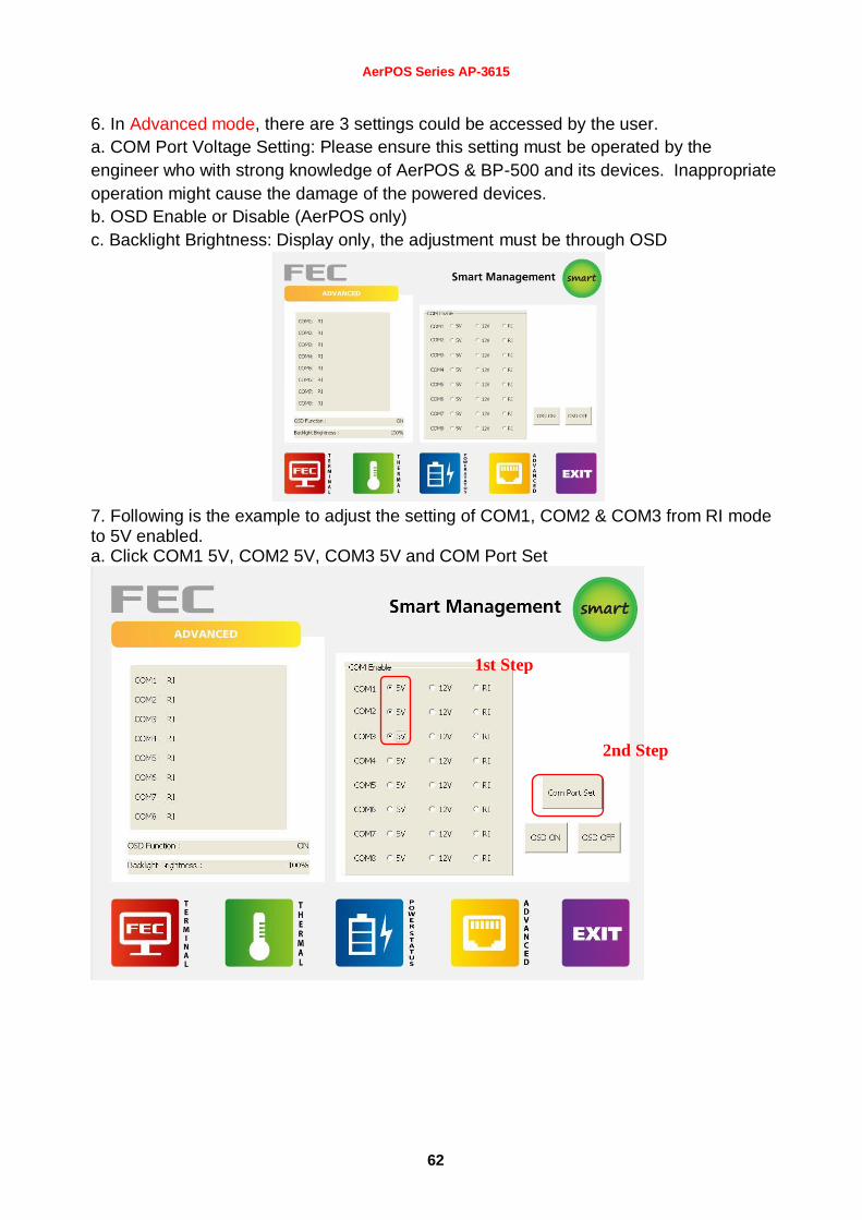
6. In Advanced mode, there are 3 settings could be accessed by the user.
a. COM Port Voltage Setting: Please ensure this setting must be operated by the
engineer who with strong knowledge of AerPOS & BP-500 and its devices. Inappropriate
operation might cause the damage of the powered devices.
b. OSD Enable or Disable (AerPOS only)
c. Backlight Brightness: Display only, the adjustment must be through OSD
7. Following is the example to adjust the setting of COM1, COM2 & COM3 from RI mode to 5V enabled. a. Click COM1 5V, COM2 5V, COM3 5V and COM Port Set
1st Step
2nd Step

AerPOS Series AP-3615
63
b. Apply the change by click the icon
c. Double confirm to apply this change
3rd Step 3rd Step 3rd Step 3rd Step
4th Step

AerPOS Series AP-3615
64
d. Shutdown the system and proceed the cold reboot 8. User could enable/disable the OSD function by select following options. After apply the setting, A cold reboot is required.