aalborg universitet aspects of semantic etl nath, rudra pratap
TRANSCRIPT
Aalborg Universitet
Aspects of Semantic ETL
Nath, Rudra Pratap
Publication date:2020
Document VersionPublisher's PDF, also known as Version of record
Link to publication from Aalborg University
Citation for published version (APA):Nath, R. P. (2020). Aspects of Semantic ETL. Aalborg Universitetsforlag. Ph.d.-serien for Det Tekniske Fakultetfor IT og Design, Aalborg Universitet
General rightsCopyright and moral rights for the publications made accessible in the public portal are retained by the authors and/or other copyright ownersand it is a condition of accessing publications that users recognise and abide by the legal requirements associated with these rights.
? Users may download and print one copy of any publication from the public portal for the purpose of private study or research. ? You may not further distribute the material or use it for any profit-making activity or commercial gain ? You may freely distribute the URL identifying the publication in the public portal ?
Take down policyIf you believe that this document breaches copyright please contact us at [email protected] providing details, and we will remove access tothe work immediately and investigate your claim.
Downloaded from vbn.aau.dk on: December 12, 2021

RU
DR
A PRATA
P DEB
NATH
ASPEC
TS OF SEM
AN
TIC ETL
ASPECTS OF SEMANTIC ETL
BYRUDRA PRATAP DEB NATH
DISSERTATION SUBMITTED 2020

T BII
D C
Aspects of Semantic ETL
Ph.D. DissertationRudra Pratap Deb Nath
Dissertation submitted June, 2020
A thesis submitted to the Technical Faculty of IT and Design at Aalborg Uni-versity (AAU) and the Department of Service and Information System Engi-neering at Universitat Politècnica de Catalunya (UPC), in partial fulfillmentof the requirements within the scope of the IT4BI-DC programme for the jointPh.D. degree in Computer Science. The thesis is not submitted to any otherorganization at the same time.
Dissertation submitted: June, 2020
PhD supervisor: Professor Torben Bach Pedersen Aalborg University, Denmark
AAU PhD Co-Supervisor: Professor Katja Hose Aalborg University, Denmark
UPC PhD Supervisor: Professor Oscar Romero Universitat Politècnica de Catalunya, Spain
AAU PhD Committee: Professor Kristian Torp (chairman) Aalborg University, Denmark
Associate Professor Olaf Hartig Linköping University, Sweden
Associate Professor Panagiotis Vassiliadis University of Ioannina, Greece
PhD Series: Technical Faculty of IT and Design, Aalborg University
Department: Department of Computer Science
ISSN (online): 2446-1628ISBN (online): 978-87-7210-657-1
Published by:Aalborg University PressKroghstræde 3DK – 9220 Aalborg ØPhone: +45 [email protected]
© Copyright by Rudra Pratap Deb Nath. Author has obtained the right to include the published and accepted articles in the thesis, with a condition that they are cited, DOI pointers and/or copyright/credits are placed prominently in the references.
Printed in Denmark by Rosendahls, 2020
Abstract
Business Intelligence (BI) tools support making better business decisions byanalyzing available organizational data. Data Warehouses (DWs), typicallystructured with the Multidimensional (MD) model, are used to store datafrom different internal and external sources processed using Extract-Transfo-rmation-Load (ETL) processes. On-Line Analytical Processing (OLAP) queriesare applied on DWs to derive important business-critical knowledge. DWand OLAP technologies perform efficiently when they are applied on datathat are static in nature and well organized in structure. Nowadays, Se-mantic Web (SW) technologies and the Linked Data (LD) principles inspireorganizations to publish their semantic data, which allow machines to under-stand the meaning of data, using the Resource Description Framework (RDF)model. One of the reasons why semantic data has become so successful isthat managing and making the data available is low effort and does not relyon a sophisticated schema.
In addition to traditional (non-semantic) data sources, the incorporationof semantic data sources into a DW raises the additional challenges of schemaderivation, semantic heterogeneity, and schema and data management modelover traditional ETL tools. Furthermore, most SW data provided by business,academic and governmental organizations includes facts and figures, whichraises new requirements for BI tools to enable OLAP-like analyses over thosesemantic (RDF) data. In this thesis, we 1) propose a layer-based ETL frame-work for handling diverse semantic and non-semantic data sources by ad-dressing the challenges mentioned above, 2) propose a set of high-level ETLconstructs for processing semantic data, 3) implement appropriate environ-ments (both programmable and GUI) to facilitate ETL processes and evaluatethe proposed solutions. Our ETL framework is a semantic ETL frameworkbecause it integrates data semantically. The following paragraphs elaborateon these contributions.
We propose SETL, a unified framework for semantic ETL. The frame-work is divided into three layers: the Definition Layer, ETL Layer, and DataWarehouse Layer. In the Definition Layer, the semantic DW (SDW) schema,sources, and the mappings among the sources and the target are defined.
iii
In the ETL Layer, ETL processes to populate the SDW from sources are de-signed. The Data Warehouse Layer manages the storage of transformed se-mantic data. The framework supports the inclusion of semantic (RDF) datain DWs in addition to relational data. It allows users to define an ontologyof a DW and annotate it with MD constructs (such as dimensions, cubes, lev-els, etc.) using the Data Cube for OLAP (QB4OLAP) vocabulary. It supportstraditional transformation operations and provides a method to generate se-mantic data from the source data according to the semantics encoded in theontology. It also provides a method to connect internal SDW data with ex-ternal knowledge bases. Hence, it creates a knowledge base, composed ofan ontology and its instances, where data are semantically connected withother external/internal data. We develop a high-level Python-based pro-grammable framework, SETL for performing the tasks mentioned above. Acomprehensive experimental evaluation comparing SETL to a solution madewith traditional tools (requiring much more hand-coding) on the use case ofDanish Agricultural and Business datasets shows that SETL provides betterperformance, programmer productivity, and knowledge base quality. Thecomparison between SETL and Pentaho Data Integration (PDI) in processinga semantic source shows that SETL is 13.5% faster than PDI. In addition tobe faster than PDI, it deals with semantic data as first-class citizen, while PDIdoes not contain specific operators for semantic data.
On top of SETL, we propose SETLCONSTUCT where we define a set ofhigh-level ETL tasks/operations to process semantic data sources. We dividethe integration process into two layers: the Definition Layer and ExecutionLayer. The Definition Layer includes two tasks that allow DW designersto define target (SDW) schemas and the mappings between (intermediate)sources and the (intermediate) target. To create mappings among the sourcesand target constructs, we provide a mapping vocabulary called Source-To-Target Mapping (S2TMAP). Different from other ETL tools, we propose anew paradigm: we characterize the ETL flow transformations at the Def-inition Layer instead of independently within each ETL operation (in theExecution Layer). This way, the designer has an overall view of the process,which generates metadata (the mapping file) that the ETL operators will readand parametrize themselves with automatically. In the Execution Layer, wepropose a set of high-level ETL operations to process semantic data sources.In addition to the cleansing, join, and data type based transformation for se-mantic data, we propose operations to generate multidimensional semanticsat the data level and to update the SDW to reflect changes in the sources.In addition, we extend SETLCONSTRUCT for enabling automatic ETL execu-tion flow generation (we call it SETLAUTO). Finally, we provide an extensiveevaluation to compare the productivity, development time, and performanceof SETLCONSTRUCT and SETLAUTO with the previous framework SETL. Theevaluation shows that SETLCONSTRUCT improves considerably over SETL in
terms of productivity, development time, and performance. The evaluationshows that 1) SETLCONSTRUCT uses 92% fewer Number of Typed Characters(NOTC) than SETL, and SETLAUTO further reduces the Number of Used Con-cepts (NOUC) by another 25%; 2) usingSETLCONSTRUCT, the developmenttime is almost cut in half compared to SETL, and is cut by another 27% us-ing SETLAUTO; 3) SETLCONSTRUCT is scalable and has similar performancecompared to SETL.
Finally, we develop a GUI-based semantic BI system SETLBI to define,process, integrate, and query semantic and non-semantic data. In additionto the Definition Layer and the ETL Layer, SETLBI has the OLAP Layer,which provides an interactive interface to enable self-service OLAP analy-sis over the semantic DW. Each layer is composed of a set of operations/-tasks. We give an ontology to formalize the intra- and inter- layer connectionsamong the components of the layer. The ETL Layer extends the the ExecutionLayer of SETLCONSTUCT by adding operations to process non-semantic datasources. We demonstrate the system using Bangladesh population census2011 datasets.
The final solution of this thesis is the BI tool SETLBI . SETLBI facilitates(1) DW designers with little/no SW knowledge to semantically integrate se-mantic and/or non-semantic data and analyze it in OLAP style, and (2) SWusers with basic MD background to define MD views over semantic data forenabling OLAP-like analysis. Additionally, SW users can enrich the gener-ated SDW’s schema with RDFS/OWL constructs. Taking the framework asa base point, researchers can aim to develop further interactive and auto-matic integration framework for SDWs. This project bridges the traditionalBI technologies and SW technologies which in turn will open the door offurther research opportunities like developing machine-understandable ETLand warehousing techniques.

Resumé
Business Intelligence (BI) værktøjer understøtter at tage bedre forretnings-beslutninger, ved at analysere tilgængelige organisatoriske data. Data Ware-houses (DWs), typisk konstrueret med den Multidimensionelle (MD) model,bruges til at lagre data fra forskellige interne og eksterne kilder, der be-handles ved hjælp af Extract-Transformation-Load (ETL) processer. On-LineAnalytical Processing (OLAP) forespørgsler anvendes på DWs for at udledevigtig forretningskritisk viden. DW og OLAP-teknologier fungerer effektivt,når de anvendes på data, som er statiske af natur og velorganiseret i struktur.I dag inspirerer Semantic Web (SW) teknologier og Linked Data (LD) prin-cipper organisationer til at offentliggøre deres semantiske data, som tilladermaskiner at forstå betydningen af denne, ved hjælp af Resource DescriptionFramework (RDF) modellen. En af grundene til, at semantiske data er blevetsuccesfuldt, er at styringen og udgivelsen af af dataene er nemt, og ikke erafhængigt af et sofistikeret skema.
Ud over problemer ved overførslen af traditionelle (ikke-semantiske) data-baser til DWs, opstår yderligere udfordringer ved overførslen af semantiskedatabaser, såsom skema nedarvning, semantisk heterogenitet samt skemaetfor data repræsentation over traditionelle ETL værktøjer. På den anden sideudgør en stor del af den semantiske data der bliver offentliggjort af virk-somheder, akademikere samt regeringer, af figurer og fakta, der igen givernye problemstillinger og krav til BI værktøjer, for at gøre OLAP lignendeanalyser over de semantiske data mulige. I denne afhandling gør vi føl-gende: 1) foreslår et lag-baseret ETL framework til at håndterer multiplesemantiske og ikke-semantiske datakilder, ved at svare på udfordringernenævnt herover, 2) foreslår en mængde af ETL operationer til at behandlesemantisk data, 3) implementerer passende miljøer (både programmerbaresamt grafiske brugergrænseflader), for at lette ETL processer og evaluere denforeslåede løsning. Vores ETL framework er et semantisk ETL framework,fordi det integrerer data semantisk. Den følgende sektion forklarer voresbidrag.
Vi foreslår SETL, et samlet framework for semantisk ETL. Frameworketer splittet i tre lag: et definitions-lag, et ETL-lag, og et DW-lag. Det seman-
vii
tiske DW (SWD) skema, datakilder, samt sammenhængen mellem datakilderog deres mål, er defineret i definitions-laget. I ETL-laget designes ETL-processer til at udfylde SDW fra datakilderne. DW-laget administrerer la-gring af transformerede semantiske data. Frameworket understøtter inklud-eringen af semantiske (RDF) data i DWs ud over relationelle data. Det giverbrugerne mulighed for at definere en ontologi for et DW og annotere medMD-konstruktioner (såsom dimensioner, kuber, niveauer osv.) ved hjælp afData Cube til OLAP (QB4OLAP) ordforrådet. Det understøtter traditionelletransformations operationer, og giver en metode til at generere semantiskedata fra de oprindelige data, i henhold til semantikken indkodet i ontolo-gien. Det muliggør også en metode til at forbinde interne SDW data medeksterne vidensbaser. Herved skaber det en vidensbase, der er sammensat afen ontologi og dets instanser, hvor data er semantisk forbundet med andreeksterne / interne data. Vi udvikler et høj niveau Python-baseret program-merbart framework for at udføre de ovennævnte opgaver. En omfattendeeksperimentel evaluering, der sammenligner SETL med en traditionel løsning(hvilket krævede meget manuel kodning), om brugen af danske landbrugs-og forretnings datasæt, viser at SETL præsterer bedre, programmør produk-tivitet og vidensbase kvalitet. Sammenligningen mellem SETL og PentahoData Integration (PDI) ved behandling af en semantisk kilde viser, at SETLer 13,5% hurtigere end PDI.
Udover SETL, foreslår vi SETLCONSTRUCT hvor vi definerer et sæt ETL-operationer på højt niveau til behandling af semantiske datakilder. Vi delerintegrationsprocessen i to lag: Definitions-lag og eksekverings-lag. Definitions-laget indeholder to opgaver, der giver DW designere muligheden for at de-finere (SDW) skemaer, og kortlægningerne mellem kilder og målet. Forat oprette kortlægning mellem kilderne og målene, leverer vi et kortlægn-ings ordforråd kaldet Source-to-Target Mapping (S2TMAP). Forskelligt fraandre ETL-værktøjer foreslår vi et nyt paradigme: vi karakteriserer ETL-flowtransformationerne i definitions-laget i stedet for uafhængigt inden forhver ETL-operation (i eksekverings-laget). På denne måde har designerenet overblik over processen, som genererer metadata (kortlægningsfilen), somETL operatørerne vil læse og parametrisere automatisk. I eksekverings-lagetforeslår vi en mængde høj niveau ETL-operationer til at behandle semantiskedatakilder. Udover rensning, sammenføjning og datatypebaseret transforma-tioner af semantiske data, foreslår vi operationer til at generere multidimen-sionel semantik på data-niveau og operationer til at opdatere et SDW forat afspejle ændringer i kilde-dataen. Derudover udvider vi SETLCONSTRUCTfor at muliggøre automatisk ETL-eksekveringsstrømgenerering (vi kalder detSETLAUTO). Endelig leverer vi en omfattende evaluering for at sammen-ligne produktivitet, udviklingstid og ydeevne for scon og SETLAUTO medden tidligere ramme SETL. Evalueringen viser, at SETLCONSTRUCT forbedresmarkant i forhold til SETL med hensyn til produktivitet, udviklingstid og
ydeevne. Evalueringen viser, at 1) SETLCONSTRUCT bruger 92% færre antalindtastede tegn (NOTC) end SETL, og SETLAUTO reducerer antallet af brugtebegreber (NOUC) yderligere med 25%; 2) ved at bruge SETLCONSTRUCT, erudviklingstiden næsten halveret sammenlignet med SETL, og skæres medyderligere 27% ved hjælp af SETLAUTO; 3) SETLCONSTRUCT er skalerbar oghar lignende ydelse sammenlignet med SETL.
Til slut udvikler vi et GUI-baseret semantisk BI system SETLBI for atdefinere, processere, integrere og lave forespørgsler på semantiske og ikke-semantiske data. Ud over definitions-laget og ETL-laget, har SETLBI etOLAP-lag, som giver en interaktiv grænseflade for at muliggøre selvbetjen-ings OLAP analyser over det semantiske DW. Hvert lag er sammensat af enmængde operationer/opgaver. Vi udarbejder en ontologi til at formalisereintra-og ekstra-lags forbindelserne mellem komponenterne og lagene. ETL-laget udvider eksekverings-laget af SETLCONSTUCT ved at tilføje operationertil at behandle ikke-semantiske datakilder. Vi demonstrerer systemet vedhjælp af Bangladesh population census 2011 datasættet.
Sammenfatningen af denne afhandling er BI-værktøjet SETLBI . SETLBIfremmer (1) DW-designere med ringe / ingen SW-viden til semantisk at in-tegrere semantiske og / eller ikke-semantiske data og analysere det i OLAPstil, og (2) SW brugere med grundlæggende MD-baggrund til at definere MD-visninger over semantiske data, der aktiverer OLAP-lignende analyse. Deru-dover kan SW-brugere berige det genererede SDW-skema med RDFS / OWL-konstruktioner. Med udgangspunkt i frameworket som et grundlag kanforskere sigte mod at udvikle yderligere interaktive og automatiske integra-tionsrammer for SDW. Dette projekt bygger bro mellem de traditionelle BI-teknologier og SW-teknologier, som igen vil åbne døren for yderligere forskn-ingsmuligheder som at udvikle maskinforståelige ETL og lagerteknikker.

Resum
Les eines d’Intel·ligència Empresarial (BI), conegudes en anglès com BusinessIntelligence, donen suport a la millora de la presa de decisions empresarialsmitjançant l’anàlisi de les dades de l’organització disponibles. Els magatzemsde dades, o data warehouse, (DWs), típicament estructurats seguint el modelMultidimensional (MD), s’utilitzen per emmagatzemar dades de diferentsfonts, tant internes com externes, processades mitjançant processos Extract-Transformation-Load (ETL). Les consultes de processament analític en línia(OLAP) s’apliquen als DW per extraure coneixement crític en l’àmbit empre-sarial. Els DW i les tecnologies OLAP funcionen de manera eficient quans’apliquen sobre dades de natura estàtica i ben estructurades. Avui en dia,les tecnologies de la Web Semàntica (SW) i els principis Linked Data (LD) in-spiren les organitzacions per publicar les seves dades en formats semàntics,que permeten que les màquines entenguin el significat de les dades, mit-jançant el llenguatge de descripció de recursos (RDF). Una de les raons perles quals les dades semàntiques han tingut tant d’èxit és que es poden ges-tionar i fer que estiguin disponibles per tercers amb poc esforç, i no depenend’esquemes de dades sofisticats.
A més de les fonts de dades tradicionals (no semàntiques), la incorpo-ració de fonts de dades semàntiques en un DW planteja reptes addicionalstals com derivar-hi esquema, l’heterogeneïtat semàntica i la representació del’esquema i les dades a través d’eines d’ETL. A més, la majoria de dades SWproporcionades per empreses, organitzacions acadèmiques o governamentalsinclouen fets i figures que representen nous reptes per les eines de BI per tald’habilitar l’anàlisi OLAP sobre dades semàntiques (RDF). En aquesta tesi, 1)proposem un marc ETL basat en capes per a la gestió de diverses fonts dedades semàntiques i no semàntiques i adreçant els reptes esmentats anterior-ment, 2) proposem un conjunt d’operacions ETL per processar dades semàn-tiques, i 3) la creació d’entorns apropiats de desenvolupament (programàticsi GUIs) per facilitar la creació i gestió de DW i processos ETL semàntics, aixícom avaluar les solucions proposades. El nostre marc ETL és un marc ETLsemàntic perquè Es capaç de considerar e integrar dades de forma semàntica.Els següents paràgrafs elaboren sobre aquests contribucions.
xi
Proposem SETL, un marc unificat per a ETL semàntic. El marc es di-videix en tres capes: la capa de definició, la capa ETL i la capa DW. A lacapa de definició, es defineixen l’esquema del DW semàntic (SDW), les fontsi els mappings entre les fonts i l’esquema del DW. A la capa ETL, es dis-senyen processos ETL per popular el SDW a partir de fonts. A la capa DW,es gestiona l’emmagatzematge de les dades semàntiques transformades. Elnostre marc dóna suport a la inclusió de dades semàntiques (RDF) en DWs,a més de dades relacionals. Així, permet als usuaris definir una ontologiad’un DW i anotar-la amb construccions MD (com ara dimensions, cubs, niv-ells, etc.) utilitzant el vocabulari Data Cube for OLAP (QB4OLAP). Tambéadmet operacions de transformació tradicionals i proporciona un mètode pergenerar semàntica de les dades d’origen segons la semàntica codificada aldocument ontologia. També proporciona un mètode per connectar l’SDWamb bases de coneixement externes. Per tant, crea una base de coneixe-ment, composta per un ontologia i les seves instàncies, on les dades estanconnectades semànticament amb altres dades externes / internes. Per fer-ho, desenvolupem un mètode programàtic, basat en Python, d’alt nivell, perrealitzar les tasques esmentades anteriorment. S’ha portat a terme un exper-iment complet d’avaluació comparant SETL amb una solució elaborada ambeines tradicional (que requereixen molta més codificació). Com a cas d’ús,hem emprat el Danish Agricultural dataset, i els resultats mostren que SETLproporciona un millor rendiment, millora la productivitat del programador ila qualitat de la base de coneixement. La comparació entre SETL i PentahoData Integration (PDI) mostra que SETL és un 13,5% més ràpid que PDI. Amés de ser més ràpid que PDI, tracta les dades semàntiques com a ciutadansde primera classe, mentre que PDI no conté operadors específics per a dadessemàntiques.
A sobre de SETL, proposem SETLCONSTUCT on definim un conjunt detasques d’alt nivell / operacions ETL per processar fonts de dades semàn-tiques i orientades a encapsular i facilitar la creació de l’ETL semàntic. Di-vidim el procés d’integració en dues capes: la capa de definició i la capad’execució. La capa de definició inclou dues tasques que permeten definirals dissenyadors de DW esquemes destí (SDW) i mappings entre fonts (o re-sultats intermedis) i l’SDW (potencialment, altres resultats intermedis). Percrear mappings entre les fonts i el SDW, proporcionem un vocabulari de map-ping anomenat Source-To-Target Mapping (S2TMAP). A diferència d’altreseines ETL, proposem un nou paradigma: les transformacions del flux ETL escaracteritzen a la capa de definició, i no de forma independent dins de cadaoperació ETL (a la capa d’execució). Aquest nou paradigma permet al dis-senyador tenir una visió global del procés, que genera metadades (el fitxer demapping) que els operadors ETL individuals llegiran i es parametritzaran au-tomàticament. A la capa d’execució proposem un conjunt d’operacions ETLd’alt nivell per processar fonts de dades semàntiques. A més de la neteja,
la unió i la transformació per dades semàntiques, proposem operacions pergenerar semàntica multidimensional i actualitzar el SDW per reflectir els can-vis en les fonts. A més, ampliem SETLCONSTRUCT per permetre la generacióautomàtica de flux d’execució ETL (l’anomenem SETLAUTO). Finalment, pro-porcionem una àmplia avaluació per comparar la productivitat, el temps dedesenvolupament i el rendiment de SETLCONSTRUCT i SETLAUTO amb el marcanterior SETL. L’avaluació demostra que SETLCONSTRUCT millora consider-ablement sobre SETL en termes de productivitat, temps de desenvolupa-ment i rendiment. L’avaluació mostra que 1) SETLCONSTRUCT utilitza un 92%menys de caràcters mecanografiats (NOTC) que SETL, i SETLAUTO redueixencara més el nombre de conceptes usats (NOUC) un altre 25%; 2) utilitzantSETLCONSTRUCT, el temps de desenvolupament es redueix gairebé a la meitaten comparació amb SETL, i es redueix un altre 27 % mitjançant SETLAUTO;3) SETLCONSTRUCT es escalable i té un rendiment similar en comparació ambSETL.
Finalment, desenvolupem un sistema de BI semàntic basat en GUI SETLBIper definir, processar, integrar i consultar dades semàntiques i no semàn-tiques. A més de la capa de definició i de la capa ETL, SETLBI té una capaOLAP, que proporciona una interfície interactiva per permetre l’anàlisi OLAPd’autoservei sobre el DW semàntic. Cada capa està composada per un con-junt d’operacions / tasques. Per formalitzar les connexions intra i inter-capesdels components de cada capa, emprem una ontologia. La capa ETL am-plia l’execució de la capa de SETLCONSTUCT afegint operacions per processarfonts de dades no semàntiques. Per últim, demostrem el sistema final mit-jançant el cens de la població de Bangladesh (2011).
La solució final d’aquesta tesi és l’eina SETLBI . SETLBI facilita (1) als dis-senyadors del DW amb pocs / sense coneixements de SW, integrar semànti-cament les dades (semàntiques o no) i analitzar-les emprant OLAP, i (2) alsusuaris de la SW els permet definir vistes sobre dades semàntiques, integrar-les amb fonts no semàntiques, i visualitzar-les segons el model MD i feranàlisi OLAP. A més, els usuaris SW poden enriquir l’esquema SDW generatamb construccions RDFS / OWL. Prenent aquest marc com a punt de partida,els investigadors poden emprar-lo per a crear SDWs de forma interactiva iautomàtica. Aquest projecte crea un pont entre les tecnologies BI i SW, i obrela porta a altres oportunitats de recerca com desenvolupar tècniques de DWi ETL comprensibles per les màquines.

Acknowledgements
Throughout this thesis, this is my favorite section because it allows me toexpress my gratitude from the deepest region of my heart to those who en-riched me by their co-operations, inspirations, knowledge, wisdom, experi-ences, and positive vibes during my PhD journey.
Firstly, I would like to express my heartiest gratitude to my supervisor,Professor Torben Bach Pedersen. I do not whether he was special to me, orgenerally, he is like that. Either I am lucky, or as a result of my previousgood deeds, I found him as a supervisor. He plays a significant role as asupervisor and true guardian during my PhD journey. I truly appreciate hisprofessionalism, sharp memory, outstanding skills in understanding my aca-demic and personal issues, and instant replies to the queries. His concreteand constructive comments, analytical skills, and visionary thinking helpedme to shape my research skills and guided me in the right direction. Next,I would like to express my sincere gratitude to my co-supervisor, ProfessorKatja Hose. Since the first day of my journey, she has been supportive andtaught me how to adapt with new social and research environments, do re-search in a structured and disciplined way. Her expertise, ideas, experience,wisdom, and organizing skills added new dimensions in my thought do-main and improved my research quality. After that, I express my gratitudeto my Host University co-supervisor Professor Oscar Romero. I think he isone of the very few persons who can understand my thinking and formu-late it. I enjoyed each and every moment of working with him. He knowshow to bring out my full potential. His encouragement, energy, knowledge,viewpoints, sense of humor, smiley face, ideas, analytical skills significantlyimproved my research skills and motivated me a lot. In short, I learned a lotof things in terms of academic, professional, and personal aspects from mysupervisors, which helped me to bring this thesis in this condition.
Further, I would like to thank all my colleagues and friends both at Aal-borg University and Universitat Politècnica de Catalunya. A special thankgoes to Assorciate Professor Christina Thomsen for helping me in all IT4BI-DC related administrative tasks. I would also remember Ilkcan Keles, SuelaIsai, Aamir Saleem, and S. R. Bhuvan for supporting me with their experi-
xv
ences and suggestions during my personal issues. I express my appreciationand gratitude to Helle Schroll and Helle Westmark for their support regard-ing the administrative matters. A special thank goes to Emil Riis Hansen fortranslating the abstract of this thesis in Danish. Professor Oscar Romero alsodeserves another thank for translating the abstract in Catalan. My thanks goto the anonymous reviewers of the papers included in this thesis. I wouldalso like to give thanks to my PhD committee members: Professor KristianTorp (Aalborg University), Associate Professor Olap Hartig (Linkoping Uni-versity), and Associate Professor Panagiotis Vassiliadis (University of Ioan-nina).
I enjoyed working in both the Danish and Spanish environments. I madea lot of friends during this PhD journey. I appreciate Danish cultures, tradi-tions, laws (especially, Janteloven, law of Jante), and their mentality. There-fore, My special thanks go to the Danish and Spanish governments to allowme to continue my PhD in their respective countries.
Finally, I would like to offer my gratitude to the energy of God and GodHimself for everything, regardless of good and bad. Thanks for directing mein the paths of beyond duality and equal vision.
Giving thanks to all again mentioned above, I end this section.
Rudra Pratap Deb NathAalborg, June 11, 2020
This research has been funded by the European Commission through the Eras-mus Mundus Joint Doctorate “Information Technologies for Business Intelligence” -Doctoral College (IT4BI-DC).
Contents
Abstract iii
Resumé vii
Resum xi
Acknowledgements xv
Thesis Details xxi
I Thesis Summary 1
Aspects of Semantic ETL 31 Introduction . . . . . . . . . . . . . . . . . . . . . . . . . . . . . . 3
1.1 Background and Motivation . . . . . . . . . . . . . . . . 31.2 Semantic ETL . . . . . . . . . . . . . . . . . . . . . . . . . 41.3 Objectives of the Thesis . . . . . . . . . . . . . . . . . . . 71.4 Structure of the Thesis Summary . . . . . . . . . . . . . . 8
2 State of the Art . . . . . . . . . . . . . . . . . . . . . . . . . . . . 93 A Semantic ETL Framework for Semantic Data Warehouses . . 11
3.1 Motivation and Problem Statement . . . . . . . . . . . . 123.2 Use Case Description . . . . . . . . . . . . . . . . . . . . 123.3 SETL Overview . . . . . . . . . . . . . . . . . . . . . . . . 143.4 Component Description . . . . . . . . . . . . . . . . . . . 153.5 Discussion . . . . . . . . . . . . . . . . . . . . . . . . . . . 22
4 High-Level ETL Constructs for Processing Semantic Data . . . 234.1 Motivation and Problem Statement . . . . . . . . . . . . 234.2 Layer-Based Semantic Data Integration Process . . . . . 244.3 The Definition Layer . . . . . . . . . . . . . . . . . . . . . 274.4 The Execution Layer . . . . . . . . . . . . . . . . . . . . . 314.5 Automatic ETL Execution Flow Generation . . . . . . . . 36
xvii
Contents
4.6 Discussion . . . . . . . . . . . . . . . . . . . . . . . . . . . 395 A Semantic BI Tool and Its Application . . . . . . . . . . . . . . 41
5.1 Motivation and Problem Statement . . . . . . . . . . . . 415.2 Architecture of the System . . . . . . . . . . . . . . . . . 415.3 A Use Case Description . . . . . . . . . . . . . . . . . . . 445.4 Demonstration . . . . . . . . . . . . . . . . . . . . . . . . 455.5 Prototype Specifications . . . . . . . . . . . . . . . . . . . 475.6 Discussion . . . . . . . . . . . . . . . . . . . . . . . . . . . 48
6 Summary of Contributions . . . . . . . . . . . . . . . . . . . . . 487 Future Work Directions . . . . . . . . . . . . . . . . . . . . . . . 51References . . . . . . . . . . . . . . . . . . . . . . . . . . . . . . . . . . 52
II Papers 57
A SETL: A Programmable Semantic Extract-Transform-Load Frameworkfor Semantic Data Warehouses 591 Introduction . . . . . . . . . . . . . . . . . . . . . . . . . . . . . . 612 Preliminary Definitions . . . . . . . . . . . . . . . . . . . . . . . 643 A Use case . . . . . . . . . . . . . . . . . . . . . . . . . . . . . . . 644 SETL Framework Overview . . . . . . . . . . . . . . . . . . . . . 685 Definition Layer . . . . . . . . . . . . . . . . . . . . . . . . . . . . 71
5.1 SDW TBox Definition . . . . . . . . . . . . . . . . . . . . 715.2 Data Source . . . . . . . . . . . . . . . . . . . . . . . . . . 745.3 Define Mapping . . . . . . . . . . . . . . . . . . . . . . . 77
6 ETL Layer . . . . . . . . . . . . . . . . . . . . . . . . . . . . . . . 816.1 Extraction . . . . . . . . . . . . . . . . . . . . . . . . . . . 816.2 Transformation . . . . . . . . . . . . . . . . . . . . . . . . 846.3 Provenance Graph . . . . . . . . . . . . . . . . . . . . . . 876.4 External linking . . . . . . . . . . . . . . . . . . . . . . . . 876.5 Load . . . . . . . . . . . . . . . . . . . . . . . . . . . . . . 89
7 Implementation . . . . . . . . . . . . . . . . . . . . . . . . . . . . 907.1 Definition Layer . . . . . . . . . . . . . . . . . . . . . . . . 907.2 ETL Layer . . . . . . . . . . . . . . . . . . . . . . . . . . . 92
8 Evaluation . . . . . . . . . . . . . . . . . . . . . . . . . . . . . . . 948.1 Productivity . . . . . . . . . . . . . . . . . . . . . . . . . . 948.2 Quality . . . . . . . . . . . . . . . . . . . . . . . . . . . . . 968.3 Performance . . . . . . . . . . . . . . . . . . . . . . . . . . 99
9 Related Work . . . . . . . . . . . . . . . . . . . . . . . . . . . . . 10410 Conclusion . . . . . . . . . . . . . . . . . . . . . . . . . . . . . . . 107References . . . . . . . . . . . . . . . . . . . . . . . . . . . . . . . . . . 107
xviii
Contents
B High-Level ETL for Semantic Data Warehouses 1131 Introduction . . . . . . . . . . . . . . . . . . . . . . . . . . . . . . 1152 Preliminary Definitions . . . . . . . . . . . . . . . . . . . . . . . 118
2.1 RDF Graph . . . . . . . . . . . . . . . . . . . . . . . . . . 1182.2 Semantic Data Source . . . . . . . . . . . . . . . . . . . . 1182.3 Semantic Data Warehouse . . . . . . . . . . . . . . . . . . 119
3 A Use Case . . . . . . . . . . . . . . . . . . . . . . . . . . . . . . . 1214 Overview of the Integration Process . . . . . . . . . . . . . . . . 1255 The Definition Layer . . . . . . . . . . . . . . . . . . . . . . . . . 1276 The Execution Layer . . . . . . . . . . . . . . . . . . . . . . . . . 137
6.1 Extraction Operations . . . . . . . . . . . . . . . . . . . . 1386.2 Transformation Operations . . . . . . . . . . . . . . . . . 1406.3 Load . . . . . . . . . . . . . . . . . . . . . . . . . . . . . . 148
7 Automatic ETL Execution Flow Generation . . . . . . . . . . . . 1487.1 Auto ETL Example . . . . . . . . . . . . . . . . . . . . . . 151
8 Evaluation . . . . . . . . . . . . . . . . . . . . . . . . . . . . . . . 1528.1 Productivity . . . . . . . . . . . . . . . . . . . . . . . . . . 1548.2 Development Time . . . . . . . . . . . . . . . . . . . . . . 1568.3 Performance . . . . . . . . . . . . . . . . . . . . . . . . . . 159
9 Related Work . . . . . . . . . . . . . . . . . . . . . . . . . . . . . 16210 Conclusion and Future Work . . . . . . . . . . . . . . . . . . . . 165A Appendix . . . . . . . . . . . . . . . . . . . . . . . . . . . . . . . 166
A.1 Semantics of the Execution Layer Operations . . . . . . . 166References . . . . . . . . . . . . . . . . . . . . . . . . . . . . . . . . . . 181
C SETLBI : An Integrated Platform for Semantic Business Intelligence 1871 Introduction . . . . . . . . . . . . . . . . . . . . . . . . . . . . . . 1892 Related Work . . . . . . . . . . . . . . . . . . . . . . . . . . . . . 1903 System Architecture . . . . . . . . . . . . . . . . . . . . . . . . . 1914 Demonstration . . . . . . . . . . . . . . . . . . . . . . . . . . . . . 194References . . . . . . . . . . . . . . . . . . . . . . . . . . . . . . . . . . 197
D Towards a Programmable Semantic Extract-Transform-Load Frame-work for Semantic Data Warehouses 1991 Introduction . . . . . . . . . . . . . . . . . . . . . . . . . . . . . . 2012 A Use case . . . . . . . . . . . . . . . . . . . . . . . . . . . . . . . 2033 The SETL Framework . . . . . . . . . . . . . . . . . . . . . . . . 205
3.1 Ontology Definition . . . . . . . . . . . . . . . . . . . . . 2063.2 Define Mapping . . . . . . . . . . . . . . . . . . . . . . . 2073.3 Extraction . . . . . . . . . . . . . . . . . . . . . . . . . . . 2073.4 Transformation . . . . . . . . . . . . . . . . . . . . . . . . 2093.5 External Linking . . . . . . . . . . . . . . . . . . . . . . . 2103.6 Loading . . . . . . . . . . . . . . . . . . . . . . . . . . . . 211
xix
Contents
4 Evaluation . . . . . . . . . . . . . . . . . . . . . . . . . . . . . . . 2124.1 Performance . . . . . . . . . . . . . . . . . . . . . . . . . . 2124.2 Quality . . . . . . . . . . . . . . . . . . . . . . . . . . . . . 2154.3 Productivity . . . . . . . . . . . . . . . . . . . . . . . . . . 217
5 Related Work . . . . . . . . . . . . . . . . . . . . . . . . . . . . . 2186 Conclusion . . . . . . . . . . . . . . . . . . . . . . . . . . . . . . . 219References . . . . . . . . . . . . . . . . . . . . . . . . . . . . . . . . . . 220
xx
Thesis Details
Thesis Title: Aspects of Semantic DataPh.D. Student: Rudra Pratap Deb NathSupervisors: Prof. Torben Bach Pedersen, Aalborg University
Prof. Katja Hose, Aalborg UniversityProf. Oscar Romero, Universitat Politècnica de Catalunya
The main body of the thesis consists of the following papers.[A] Rudra Pratap Deb Nath, Katja Hose, Torben Bach Pedersen, and Oscar
Romero. “SETL: A programmable semantic extract-transform-loadframework for semantic data warehouses.”. In: Information Systems,Vol.68, pp. 17–43, Elsevier, 2017.
[B] Rudra Pratap Deb Nath, Oscar Romero, Torben Bach Pedersen, andKatja Hose. “High Level ETL for Semantic Data Warehouses”. Sub-mitted to: Semantic Web Journal, IOS Press, 2020.
[C] Rudra Pratap Deb Nath, Katja Hose, Torben Bach Pedersen, OscarRomero, and Amrit Bhattacharjee. “SETLBI : An Integrated Platformfor Semantic Business Intelligence ”. In: Proceedings of the World WideWeb Conference 2020, Taipei .
In addition to the main papers, Paper D has also been included. PaperA is the extended version of Paper D, thus Paper D can be considered as asubset of Paper A.
[D] Rudra Pratap Deb Nath, Katja Hose, and Torben Bach Pedersen: “To-wards a Programmable Semantic Extract-Transform-Load Frameworkfor Semantic Data Warehouses”. In : Proceedings of the ACM EighteenthInternational Workshop on Data Warehousing and OLAP, DOLAP 2015,Melbourne, VIC, Australia, pp.15-24, ACM, 2015.
This thesis has been submitted for assessment in partial fulfilment of the PhDdegree. The thesis is based on the submitted or published scientific papers,
xxi
Thesis Details
which are listed above. Parts of the papers are used directly or indirectlyin the summary of the thesis. As a part of the assessment, co-author state-ments have been made available to the assessment committee and those arealso available at the at the Technical Faculty of IT and Design at AalborgUniversity and the Department of Service and Information System Engineer-ing at Universitat Politècnica de Catalunya. The permission for using thepublished articles in the thesis has been obtained from the correspondingpublishers with the conditions that they are cited and DOI pointers and/orcopyrights/credits are placed prominently in the references.
Rudra Pratap Deb NathAalborg University, June 11, 2020
xxii
Part I
Thesis Summary
1

Aspects of Semantic ETL
1 Introduction
1.1 Background and Motivation
Business Intelligence (BI) supports organizations by providing techniquesand tools to derive intelligent business decisions by analyzing their data [31].In a BI system, data come from different data sources and are integratedinto a Data Warehouse (DW) for analytical purposes [35]. The integrationprocess for extracting data from different sources, translating it according tothe underlying semantics of the DW, and loading it into the DW is knownas Extract-Transform-Load (ETL). Typically, a DW is designed following theMultidimensional (MD) model, where data are viewed in an n-dimensionalspace, generally known as a data cube, composed of facts (the cells of thecube) and dimensions (the axes of the cube) [39]. Dimensions are organizedinto hierarchies (composed of a number of levels) to explore and (dis)aggrega-te fact measures (e.g., numerical data) at various levels of detail. For exam-ple, the Administrative hierarchy (ADM5 → ADM4 → ADM3 → ADM2 →ADM1) of the Geography dimension allows to (dis)aggregate the populationof Bangladesh at various administrative levels of detail. The MD model en-ables Online Analytical Processing (OLAP) [35] queries, where data cubesare explored through user-friendly interfaces. Hence, OLAP has been widelyused by business and non-technical users for data analysis and decision-making [54].
DW and OLAP technologies perform efficiently when they are applied ondata that are static in nature and well organized in structure [1]. Nowadays,Semantic Web (SW) technologies and the Linked Data (LD) principles inspireorganizations to publish their business-related data, which allows machinesto understand the meaning of data. Therefore, besides analyzing internaldata available in a DW, it is often desirable to incorporate (external) semanticdata sources into the DW to derive the needed business knowledge. More-over, most SW data provided by international and governmental organiza-tions include facts and figures, which can be described in an MD manner to
3
enable OLAP-like analyses [32]. The semantics of data in semantic sourcesare specified by using Internationalized Resource Identifiers (IRIs), providingcommon terminology, semantically linking with published information, andproviding further knowledge to allow reasoning [6].
Semantic data is expressed in Resource Description Framework (RDF) [57],where each resource is described by a set of statements called triples. Oneof the drawbacks of semantic data is that they are often described withoutany schema (i.e., only instances are delivered, not the schema) or with anincomplete schema. Moreover, different sources describe the same domain intheir own implicit schema, introducing semantic heterogeneity problems.
In addition to the traditional (non-semantic) data, the incorporation ofthose (external) semantic data into a DW raises additional challenges ofschema derivation, semantic annotation, semantic heterogeneity, as well asschema and data management model over traditional DW technologies andETL tools. The main drawback of a state-of-the-art Relational Database Man-agement System (RDBMS)-based DW is that it is strictly schema dependentand less flexible to evolving business requirements. To cover new businessrequirements, every step of the development cycle needs to be updated tocope with the new requirements. This update process is time-consuming andcostly and is sometimes not adjustable with the current setup of the DW;hence, it introduces the need for a novel approach.
In summary, the limitations of traditional ETL tools to process semanticdata sources are: (1) they do not fully support semantic-aware data, (2) theyare entirely schema dependent (i.e., cannot handle data expressed withoutany schema), (3) they do not focus on meaningful semantic relationships tointegrate data from disparate sources, and (4) they neither support to cap-ture the semantics of data nor support to derive new information by activeinference and reasoning on the data [43].
Thus, a DW with semantic data sources in addition to traditional datasources requires more powerful techniques to define, integrate, transform,update, and load data semantically, which are the research challenges of thisthesis.
1.2 Semantic ETL
To build a DW system with heterogeneous (semantic and non-semantic) datasources, the integration process should be able to deal with data semanticsas a first-class citizen. Semantic Web (SW) technologies fulfill these needs asthey allow to add semantics on both data and schema level in the integra-tion process. SW technologies aim at presenting and exchanging data in amachine-readable and understandable format.
On the SW, RDF is used for presenting and exchanging data in a machine-readable format. In the RDF data model, information is presented in a set of
4
1. Introduction
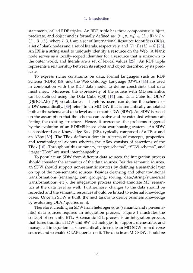
statements, called RDF triples. An RDF triple has three components: subject,predicate, and object and is formally defined as: (v1, v2, v3) ∈ (I ∪ B)× I ×(I ∪ B ∪ L), where I, B, L are a set of International Resource Identifiers (IRIs),a set of blank nodes and a set of literals, respectively, and (I ∩ B∩ L) = ∅ [25].An IRI is a string used to uniquely identify a resource on the Web. A blanknode serves as a locally-scoped identifier for a resource that is unknown tothe outer world, and literals are a set of lexical values [25]. An RDF triplerepresents a relationship between its subject and object described by its pred-icate.
To express richer constraints on data, formal languages such as RDFSchema (RDFS) [58] and the Web Ontology Language (OWL) [44] are usedin combination with the RDF data model to define constraints that datamust meet. Moreover, the expressivity of the source with MD semanticscan be defined using the Data Cube (QB) [14] and Data Cube for OLAP(QB4OLAP) [19] vocabularies. Therefore, users can define the schema ofa DW semantically. [39] refers to an MD DW that is semantically annotatedboth at the schema and data level as a semantic DW (SDW). An SDW is basedon the assumption that the schema can evolve and be extended without af-fecting the existing structure. Hence, it overcomes the problems triggeredby the evolution of an RDBMS-based data warehousing system. An SDWis considered as a Knowledge Base (KB), typically composed of a TBox andan ABox [39]. The TBox defines a domain in terms of concepts, properties,and terminological axioms whereas the ABox consists of assertions of theTBox [16]. Throughout this summary, “target schema”, “SDW schema”, and“target TBox” are used interchangeably.
To populate an SDW from different data sources, the integration processshould consider the semantics of the data sources. Besides semantic sources,an SDW should support non-semantic sources by defining a semantic layeron top of the non-semantic sources. Besides cleansing and other traditionaltransformations (renaming, join, grouping, sorting, date/string/numericaltransformations, etc.), the integration process should annotate MD seman-tics at the data level as well. Furthermore, changes to the data should berecorded and the semantic resources should be linked to external knowledgebases. Once an SDW is built, the next task is to derive business knowledgeby evaluating OLAP queries on it.
Therefore, creating an SDW from heterogeneous (semantic and non-sema-ntic) data sources requires an integration process. Figure 1 illustrates theconcept of semantic ETL. A semantic ETL process is an integration processthat fuses traditional DW and SW technologies to support, orchestrate, andmanage all integration tasks semantically to create an MD SDW from diversesources and to enable OLAP queries on it. The data in an MD SDW should be
5
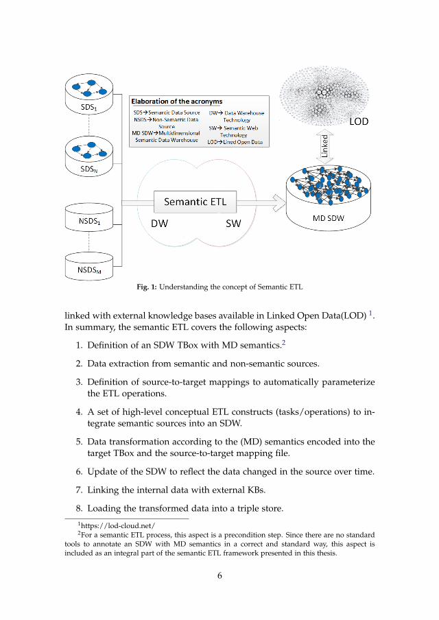
Fig. 1: Understanding the concept of Semantic ETL
linked with external knowledge bases available in Linked Open Data(LOD) 1.In summary, the semantic ETL covers the following aspects:
1. Definition of an SDW TBox with MD semantics.2
2. Data extraction from semantic and non-semantic sources.
3. Definition of source-to-target mappings to automatically parameterizethe ETL operations.
4. A set of high-level conceptual ETL constructs (tasks/operations) to in-tegrate semantic sources into an SDW.
5. Data transformation according to the (MD) semantics encoded into thetarget TBox and the source-to-target mapping file.
6. Update of the SDW to reflect the data changed in the source over time.
7. Linking the internal data with external KBs.
8. Loading the transformed data into a triple store.
1https://lod-cloud.net/2For a semantic ETL process, this aspect is a precondition step. Since there are no standard
tools to annotate an SDW with MD semantics in a correct and standard way, this aspect isincluded as an integral part of the semantic ETL framework presented in this thesis.
6
1. Introduction
9. Enabling OLAP queries on the SDW.3
1.3 Objectives of the Thesis
The hypothesis of this thesis is:“In the context of highly heterogeneous data integration processes, considering
semantics as first-class citizen facilitates the integration process by providing au-tomation and lower entry barriers for non-technical users."
The overall objective of this thesis is to develop a semantic ETL frame-work. The following incremental sub-objectives (i.e., they build on top of theprevious ones) to meet this overall objective are defined:
1. Propose and develop an end-to-end semantic ETL framework to inte-grate semantic and non-semantic sources into an SDW: The frameworkshould allow users to define the target TBox with MD semantics, ex-tract semantic and non-semantic data, transform data according to thesemantics of the target TBox, link data with external KBs, and loaddata into a triple store. The framework should be implemented usinga high-level language so that ETL developers can accomplish differentintegration tasks considering semantics. A comprehensive experimen-tal evaluation of the framework should be performed. This objectivecovers the following aspects of semantic ETL pointed in Section 1.2: 1,2, 5, 7, and 8.
2. Propose and develop a prototype of a set of basic high-level ETL con-structs (tasks/operations) to process semantic data sources and inte-grate semantic data into an SDW: Here, a set of ETL constructs (tasks/-operations) is proposed so that other integration tools can utilize thosecomponents to enable semantic integration. Further, three types of di-mensional updates defined by Ralph Kimball in [34] should be appliedin the context of an SDW. Importantly, there should be a mechanism toovercome manual mappings (typical of ETL tools) at the ETL operationlevel. The prototype should be evaluated in terms of productivity, de-velopment time and performance by comparing it with the frameworkproposed in Objective 1. This objective covers the following aspects ofsemantic ETL pointed in Section 1.2: 1, 2 (partly - only for semanticdata sources), 3, 4 , 5, 6, 7, and 8.
3. Propose and develop a prototype of a semantic BI tool (like traditionalBI tools) that supports, orchestrates, and manages all integration tasksand enables self-service OLAP analysis over an SDW: This GUI-basedBI tool should enrich the framework of Objective 1 with the high-level
3In a traditional ETL, this aspect is outside of an ETL process. However, this aspect isincluded here to validate the quality of the produced MD semantic data.
7
ETL constructs discussed in Objective 2 and additionally add an OLAPinterface to enable self-service OLAP-analysis over an SDW. This objec-tive covers the following aspects of semantic ETL pointed in Section 1.2:1, 2, 3, 4, 5, 6, 8, and 9.
Aspects of Semantic ETL
Proposing a semantic ETL framework that integrates semantic and non-semantic sources into a semantic Data
Warehouse and evaluation of the framework.
Proposing and formalizing the high-level ETL constructs required to process and integrate semantic data into a
semantic Data Warehouse.
Developing a BI tool that facilitates to integrate heterogenous data semantically and enables self-service
OLAP-analysis over a semantic Data Warehouse.
Paper B
Paper C
Paper A Paper D Paper A Paper D
Solutions(Papers)
SETL
SETLCONSTRUCT
SETLBI
ObjectivesObjectivesObjectives
Fig. 2: The connections between the objectives and the outcomes of the thesis.
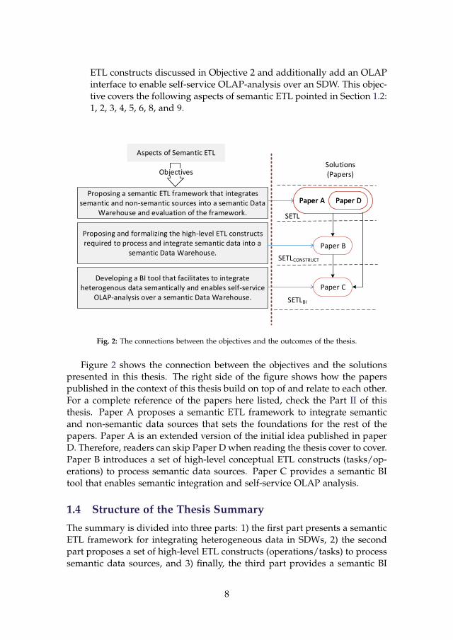
Figure 2 shows the connection between the objectives and the solutionspresented in this thesis. The right side of the figure shows how the paperspublished in the context of this thesis build on top of and relate to each other.For a complete reference of the papers here listed, check the Part II of thisthesis. Paper A proposes a semantic ETL framework to integrate semanticand non-semantic data sources that sets the foundations for the rest of thepapers. Paper A is an extended version of the initial idea published in paperD. Therefore, readers can skip Paper D when reading the thesis cover to cover.Paper B introduces a set of high-level conceptual ETL constructs (tasks/op-erations) to process semantic data sources. Paper C provides a semantic BItool that enables semantic integration and self-service OLAP analysis.
1.4 Structure of the Thesis Summary
The summary is divided into three parts: 1) the first part presents a semanticETL framework for integrating heterogeneous data in SDWs, 2) the secondpart proposes a set of high-level ETL constructs (operations/tasks) to processsemantic data sources, and 3) finally, the third part provides a semantic BI
8
2. State of the Art
tool and its application. Section 2 discusses the research related to the se-mantic ETL. Section 3 presents the first part of the thesis whereas Section 4and Section 5 summarize the second and third parts of the thesis respectively.The contribution of the thesis are summarized in Section 6. Finally, Section 7points to future work.
2 State of the Art
Nowadays, combining BI and SW technologies has become an emerging re-search topic as it opens the door to interesting research opportunities. Asa DW deals with both internal and (increasingly) external data presented inheterogeneous formats, especially in RDF format, semantic issues should beconsidered in the integration process [1]. On the other hand, the availabilityof SW data gives rise to new requirements for BI tools to enable OLAP-styleanalysis over this type of data. Therefore, the existing research related to se-mantic ETL is divided into two lines: 1) on the one hand, the use of SW tech-nologies to physically integrate heterogeneous sources and 2) on the otherhand, enabling OLAP analysis over SW data.
A prominent research work following the first research line is [51], whichpresents an ontology-based approach for enabling the construction of ETLflows. At first, the schema of both the sources and the DW are defined by acommon graph-based model, named the datastore graph. Then, the seman-tics of the datastore graphs of the data sources and the DW are describedby generating an (OWL-based) application ontology, and the mappings be-tween the sources and the target are established through that ontology. Theyaddress in this way the heterogeneity issues among the source and targetschemata and finally demonstrated how the use of an ontology enables ahigh degree of automation from the source to the target attributes, along withthe appropriate ETL transformations. Nonetheless, computationally complexETL operations like slowly changing dimensions and the annotation of theapplication ontology with MD semantics are not addressed in this research.Therefore, OLAP queries cannot be applied on the generated DW.
Another existing work [5] aligned to this line has proposed a methodol-ogy describing some important steps required to make an SDW, which en-ables to integrate data from semantic databases. This approach also missesthe annotation of SDW with MD semantics. [52] has proposed an approachto support data integration tasks in two steps: 1) constructing ontologiesfrom XML and relational sources and 2) integrating the derived ontologiesby means of existing ontology alignment and merging techniques. However,ontology alignment techniques are complex and error-prone. [4] presents asemantic ETL framework at the conceptual level. This approach utilizes theSW technologies to facilitate the integration process and discusses the use
9
of different available tools to perform different steps of the ETL process. [2]presents a method to spatially integrate a Danish Agricultural dataset and aDanish Business dataset using an ontology. The approach uses SQL viewsand other manual processes to cleanse the data and Virtuoso for creating andstoring integrated RDF data. [36] presents UnifiedViews, an open-source ETLframework that supports management of RDF data. Based on the SPARQLqueries, they define four types of Data Processing Units (DPUs): Extractor,Transformer, Loader, and Quality Assessor. However, the DPUs do not sup-port to generate MD RDF data.
About the second research line mentioned, a prominent study relatedto it is [42], which outlines a semi-automatic method for incorporating SWdata into a traditional MD data management system for OLAP analysis. Themethod the authors proposed here allows an analyst to accomplish the fol-lowing tasks: 1) designing the MD schema from the TBox of an RDF dataset,2) extracting the facts from the ABox of the dataset and populating the MDfact table, and 3) producing the dimension hierarchies from instances of thefact table and the TBox to enable MDX queries over the generated DW. How-ever, the generated DW no longer preserves the SW data principles definedin [27]; thus, OLAP analysis directly over SW data is yet to be addressed.With the purpose of fixing this issue, [11] introduces the notion of a lens,called the analytical schema, over the RDF dataset. An analytical schema is agraph of classes and properties where each node of the schema presents a setof facts that can be analyzed by traversing the reachable nodes. [28] presentsa self-service OLAP endpoint for an RDF dataset. This approach first su-perimposes an MD schema over the RDF dataset. Then, a semantic analysisgraph is generated on top of that MD schema where each node of the graphpresents an analysis situation corresponding to an MD query, and an edgeindicates to a set of OLAP operations.
Both [11] and [28] require either a lens or a semantic analysis graph to de-fine MD views over an RDF dataset. Since most published SW data containsfacts and figures, W3C recommends the Data Cube (QB) [14] vocabulary tostandardize the publication of SW data with MD semantics. Although QBis appropriate to publish statistical data and several publishers (e.g., [47])have already used the vocabulary for publishing statistical datasets, it haslimitations to define MD semantics properly. The QB4OLAP [19] vocabularyenriches QB to support MD semantics by providing constructs to define 1) acube structure in terms of different level of dimensions, measures, and attach-ing aggregate functions with measures and 2) a dimension structure in termsof levels, level attributes, relationships and the cardinality of relationshipsamong the levels, and hierarchies of the dimension. Therefore, MD data canbe published either by enriching data already published using QB with di-mension levels, level members, dimension hierarchies, and the association ofaggregate functions to measures without affecting the existing observations
10
3. A Semantic ETL Framework for Semantic Data Warehouses
(for example, [56]) or using QB4OLAP from scratch (for example, [22], [30],and [39]).
In [33], the authors have presented an approach to enable OLAP opera-tions on a single data cube published using the QB vocabulary and shown theapplicability of their OLAP-to-SPARQL mapping in answering business ques-tions in the financial domain. However, their OLAP-to-SPARQL mappingmay not result in the most efficient SPARQL query and requires additionalefforts and a longer time to get the results as they consider that the cube isqueried on demand and the DW is not materialized. The authors in [54, 55]presented a semi-automatic method to enrich the QB dataset with QB4OLAPconstructs. Nevertheless, the OLAP interface of their system requires endusers to be familiar with either QL [10] or complex SPARQL queries to runOLAP queries.
After analyzing the main efforts on the two research lines identified whenbridging DW and SW, we can draw some conclusions. Although each pa-per described above addresses one or multiple aspects of a semantic ETLframework, there is no single platform that supports all (target definition,source-to-target mappings generation, ETL generations, target population,evolution, update and OLAP-analysis). Further, there is no clear definition ofhow to orchestrate such steps into a single end-to-end flow. This thesis aimsat developing a semantic ETL framework that supports, orchestrates, andmanages all integration tasks to create an SDW and enable OLAP querieson it. To successfully reach the aim of the thesis, the framework has beendesigned in an incremental manner. First, a Python based programmablesemantic ETL framework, named SETL is proposed in [39]. This is a kindof semantic version of pygramETL [53], a programmable ETL framework fortraditional DWs. SETL provides various modules, classes, and methods to1) extract semantic-aware data, geospatial data, and relational data, 2) in-tegrate source data semantically using a target TBox defined with/withoutMD semantics, 3) store the data as semantic data, and 4) linking internal SDWdata with external knowledge bases. Then, on top of SETL, SETLCONSTRUCTis proposed in [17] where the set of basic high-level ETL tasks/operationsto process semantic data are discussed. Finally, a complete BI tool namedSETLBI is developed in [16], which facilitates end-users to integrate hetero-geneous data semantically and query on integrated data using interactivegraphical interfaces.
3 A Semantic ETL Framework for Semantic DataWarehouses
This section is a summary of Paper A [39].
11
3.1 Motivation and Problem Statement
In addition to their internal organizational data, companies are (increasingly)showing interest in the knowledge encoded in large semantically annotatedrepositories that are locally or publicly available such as DBpedia [3], Free-base [8], Eurostat 4 or the datasets available in Linked Open Data (LOD). Forexample, a European company may want to analyze their internal productsales based on population and sex in different regions, which is available inEurostat [17]. The use of SW technologies together with traditional DW tech-nologies supports this open world scenario by addressing the limitations ofcurrent database-centric ETL tools discussed in Section 1.1. Therefore, theDW community is showing increasing interest in using SW technologies inthe integration process. In [1, 4, 51], authors have used SW technologies todesign conceptual frameworks of different phases of ETL processes; however,no one has so far offered an integrated framework to build a Semantic DW(SDW) that covers all integration phases, namely target definition, source totarget mappings, (semantic and non-semantic) source extraction, transforma-tion, linking, and loading [39]. In this section, a semantic ETL frameworknamed SETL is presented. SETL allows to process and integrate heteroge-neous data semantically by bridging SW and DW technologies. As discussedlater, SETL supports all integration phases.
The unique contributions of SETL are: 1) It allows users to define theintensional knowledge (schema) of an SDW using ontological constructs.Users can annotate the schema with MD constructs (facts, dimensions, lev-els, cube, level attribute, and so on) using the QB [14] and QB4OLAP [19]vocabularies. 2) It allows processing both semantic and non-semantic datasources. A non-semantic data source is processed by creating a semanticlayer on top of it. 3) It provides functionality to generate data (in the form ofRDF triples) from diverse sources according to the semantics encoded in theschema of the SDW. 4) It also provides functionality to connect internal datawith other internal/external data semantically [39]. A high-level Python-based programmable framework is developed for performing the integrationtasks mentioned above. The programmable framework facilitates ETL devel-opers by providing a higher abstraction level (in the form of modules, classes,and methods) that lowers the entry barriers. The following sections describethe use case used in this section, the architecture of SETL, the description ofSETL components, and an overall discussion.
3.2 Use Case Description
This section describes the source datasets and the final target TBoxes for in-tegrating and understanding the MD knowledge of those datasets. The three
4https://ec.europa.eu/eurostat/web/nuts/linked-open-data
12
3. A Semantic ETL Framework for Semantic Data Warehouses
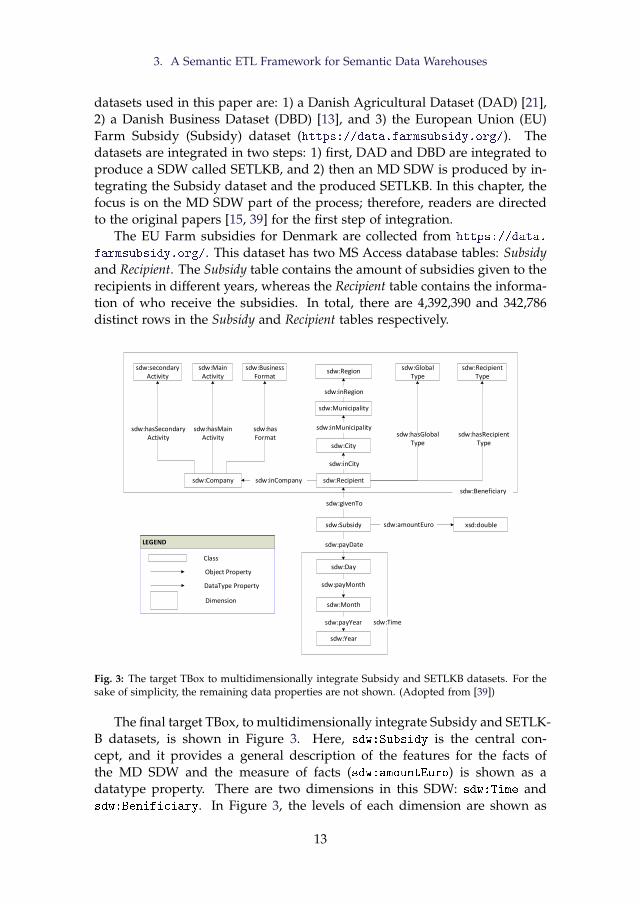
datasets used in this paper are: 1) a Danish Agricultural Dataset (DAD) [21],2) a Danish Business Dataset (DBD) [13], and 3) the European Union (EU)Farm Subsidy (Subsidy) dataset (https://data.farmsubsidy.org/). Thedatasets are integrated in two steps: 1) first, DAD and DBD are integrated toproduce a SDW called SETLKB, and 2) then an MD SDW is produced by in-tegrating the Subsidy dataset and the produced SETLKB. In this chapter, thefocus is on the MD SDW part of the process; therefore, readers are directedto the original papers [15, 39] for the first step of integration.
The EU Farm subsidies for Denmark are collected from https://data.
farmsubsidy.org/. This dataset has two MS Access database tables: Subsidyand Recipient. The Subsidy table contains the amount of subsidies given to therecipients in different years, whereas the Recipient table contains the informa-tion of who receive the subsidies. In total, there are 4,392,390 and 342,786distinct rows in the Subsidy and Recipient tables respectively.
sdw:Recipient
sdw:Day
sdw:Subsidy
sdw:Municipality
sdw:City
sdw:Region
sdw:Month
sdw:Year
sdw:Company
sdw:secondaryActivity
sdw:MainActivity
sdw:BusinessFormat
sdw:Global Type
sdw:RecipientType
sdw:inCompany
sdw:payDate
sdw:payMonth
sdw:payYear
sdw:hasSecondaryActivity
sdw:hasMainActivity
sdw:hasFormat
sdw:inMunicipality
sdw:inCity
sdw:inRegion
sdw:hasRecipientType
sdw:hasGlobalType
sdw:givenTo
xsd:doublesdw:amountEuro
sdw:Beneficiary
sdw:Time
LEGEND
Class
Object Property
DataType Property
LEGEND
Class
Object Property
DataType Property
Dimension
Fig. 3: The target TBox to multidimensionally integrate Subsidy and SETLKB datasets. For thesake of simplicity, the remaining data properties are not shown. (Adopted from [39])
The final target TBox, to multidimensionally integrate Subsidy and SETLK-B datasets, is shown in Figure 3. Here, sdw:Subsidy is the central con-cept, and it provides a general description of the features for the facts ofthe MD SDW and the measure of facts (sdw:amountEuro) is shown as adatatype property. There are two dimensions in this SDW: sdw:Time andsdw:Benificiary. In Figure 3, the levels of each dimension are shown as
13
a concept, and the hierarchies of each dimension—how the levels of eachdimension are connected to each other through object properties to createdifferent branches from sdw:Subsidy—are also shown.
3.3 SETL Overview
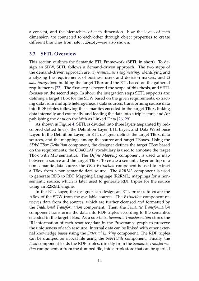
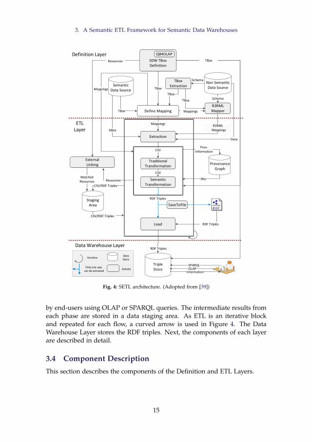
This section outlines the Semantic ETL Framework (SETL in short). To de-sign an SDW, SETL follows a demand-driven approach. The two steps ofthe demand-driven approach are: 1) requirements engineering: identifying andanalyzing the requirements of business users and decision makers, and 2)data integration: building the target TBox and the ETL based on the gatheredrequirements [23]. The first step is beyond the scope of this thesis, and SETLfocuses on the second step. In short, the integration steps SETL supports are:defining a target TBox for the SDW based on the given requirements, extract-ing data from multiple heterogeneous data sources, transforming source datainto RDF triples following the semantics encoded in the target TBox, linkingdata internally and externally, and loading the data into a triple store, and/orpublishing the data on the Web as Linked Data [26, 29].
As shown in Figure 4, SETL is divided into three layers (separated by red-colored dotted lines): the Definition Layer, ETL Layer, and Data WarehouseLayer. In the Definition Layer, an ETL designer defines the target TBox, datasources, and the mappings among the source and target TBoxes. Using theSDW TBox Definition component, the designer defines the target TBox basedon the requirements; the QB4OLAP vocabulary is used to annotate the targetTBox with MD semantics. The Define Mapping component is used to mapbetween a source and the target TBox. To create a semantic layer on top of anon-semantic data source, the TBox Extraction component is used to extracta TBox from a non-semantic data source. The R2RML component is usedto generate RDB to RDF Mapping Language (R2RML) mappings for a non-semantic source, which is later used to generate RDF triples for the sourceusing an R2RML engine.
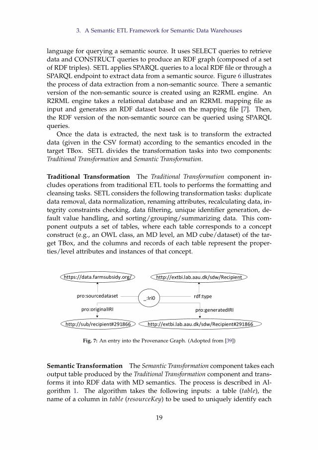
In the ETL Layer, the designer can design an ETL process to create theABox of the SDW from the available sources. The Extraction component re-trieves data from the sources, which are further cleansed and formatted bythe Traditional Transformation component. Then, the Semantic Transformationcomponent transforms the data into RDF triples according to the semanticsencoded in the target TBox. As a sub-task, Semantic Transformation stores theIRI information of each resource/data in the Provenance graph to preservethe uniqueness of each resource. Internal data can be linked with other exter-nal knowledge bases using the External Linking component. The RDF triplescan be dumped as a local file using the SaveToFile component. Finally, theLoad component loads the RDF triples, directly from the Semantic Transforma-tion component or from the dumped file, into a triplestore that can be queried
14
3. A Semantic ETL Framework for Semantic Data Warehouses
Non SemanticData Source
SemanticData Source
Define Mapping
R2RMLMapper
SDW TBox Definition
Semantic Transformation
Traditional Transformation
Extraction
External Linking
Load
ProvenanceGraph
TripleStore
TBox
Mappings
CSV
CSV
SPARQL
Information
Prov. Information
IRIs
TBoxSchema
TBox
ABox
MatchedResources Resources
Mappings
QB4OLAP
Only one way can be activated
Iterative DataStore
Activity OLAP
StagingArea
CSV/RDF Triples
SaveToFile
RDF Triples
RDF Triples
Definition Layer
ETL Layer
Data Warehouse Layer
CSV/RDF Triples
R2RML Mappings
Data
RDF Triples
TBox Extraction
Schema
Resources
Mappings
TBox
TBox
Fig. 4: SETL architecture. (Adopted from [39])
by end-users using OLAP or SPARQL queries. The intermediate results fromeach phase are stored in a data staging area. As ETL is an iterative blockand repeated for each flow, a curved arrow is used in Figure 4. The DataWarehouse Layer stores the RDF triples. Next, the components of each layerare described in detail.
3.4 Component Description
This section describes the components of the Definition and ETL Layers.
15
The Definition Layer
The Definition Layer is composed of four components: SDW TBox Definition,TBox Extraction, Define Mapping and R2RML Mapper, and an overview of eachcomponent is presented in the following paragraphs.
SDW TBox Definition As data sources are defined heterogeneously, it isvital to capture the semantics of the data at the conceptual level. To designan SDW, SETL uses ontological constructs (for example, Figure 3 shows theontology of the SDW of our use case). SETL uses RDFS/OWL to define theformal semantics encoded in the ontology (TBox). In OWL, owl:Class andrdfs:Property are used to define concepts and properties of the TBox. Thehierarchical relationships among the concepts and properties are presentedby rdfs:SubClassOf and rdfs:SubPropertyOf, respectively, and rdfs:domain
and rdfs:range are used to relate properties with concepts. As an SDW isdefined with multidimensional constructs, SETL uses QB and QB4OLAP vo-cabularies to enrich the TBox with MD semantics.
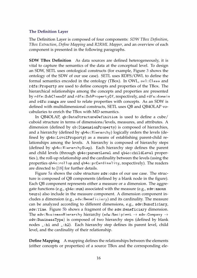
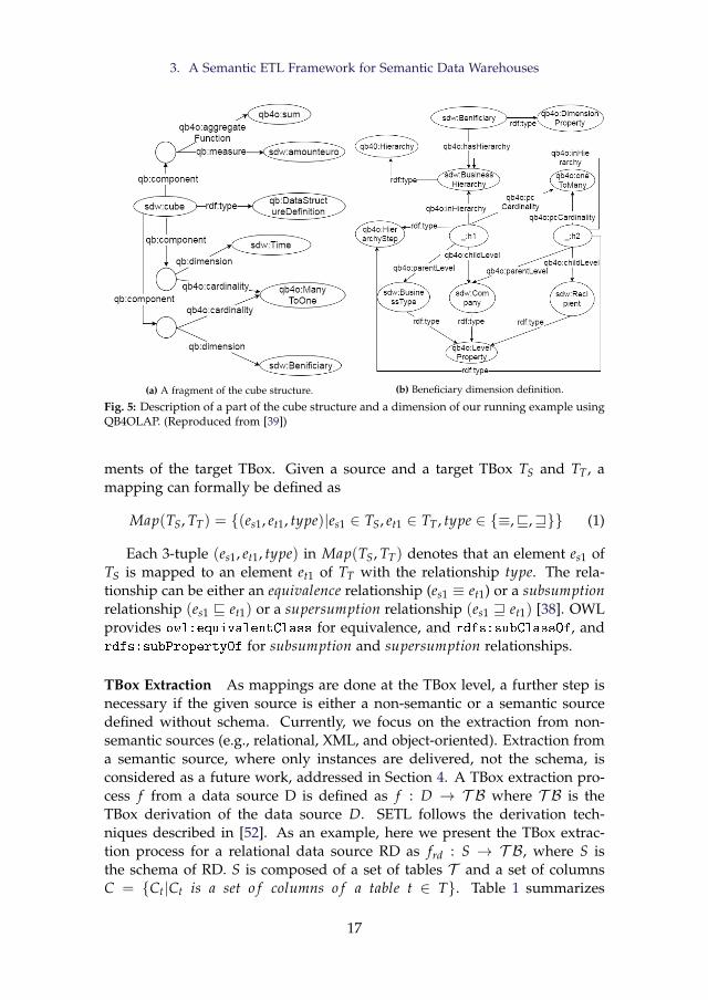
In QB4OLAP, qb:DataStructureDefinition is used to define a cube/cuboid structure in terms of dimensions/levels, measures, and attributes. Adimension (defined by qb:DimensionProperty) is composed of hierarchies,and a hierarchy (defined by qb4o:Hierarchy) logically orders the levels (de-fined by qb4o:LevelProperty) as a means of establishing parent-child re-lationships among the levels. A hierarchy is composed of hierarchy steps(defined by qb4o:HierarchyStep). Each hierarchy step defines the parentand child levels (through qb4o:parentLevel and qb4o:childLevel proper-ties ), the roll-up relationship and the cardinality between the levels (using theproperties qb4o:rollup and qb4o:pcCardinality, respectively). The readersare directed to [18] for further details.
Figure 5a shows the cube structure sdw:cube of our use case. The struc-ture is composed of QB components (defined by a blank node in the figure).Each QB component represents either a measure or a dimension. The aggre-gate functions (e.g., qb4o:sum) associated with the measure (e.g., sdw:amoun-teuro) also include in the measure component. A dimension component in-cludes a dimension (e.g., sdw:Beneficiary) and its cardinality. The measurecan be analyzed according to different dimensions, e.g., sdw:Beneficiary,sdw:Time. Figure 5b shows a fragment of the sdw:Beneficiary dimension.The sdw:BusinessHierarchy hierarchy (sdw:Recipient → sdw:Company →sdw:BusinessType) is composed of two hierarchy steps (defined by blanknodes _:h1 and _:h2). Each hierarchy step defines its parent level, childlevel, and the cardinality of their relationship.
Define Mapping A mapping defines the relationships between the elements(either concepts or properties) of a source TBox and the corresponding ele-
16
3. A Semantic ETL Framework for Semantic Data Warehouses
(a) A fragment of the cube structure. (b) Beneficiary dimension definition.
Fig. 5: Description of a part of the cube structure and a dimension of our running example usingQB4OLAP. (Reproduced from [39])
ments of the target TBox. Given a source and a target TBox TS and TT , amapping can formally be defined as
Map(TS, TT) = {(es1, et1, type)|es1 ∈ TS, et1 ∈ TT , type ∈ {≡,v,w}} (1)
Each 3-tuple (es1, et1, type) in Map(TS, TT) denotes that an element es1 ofTS is mapped to an element et1 of TT with the relationship type. The rela-tionship can be either an equivalence relationship (es1 ≡ et1) or a subsumptionrelationship (es1 v et1) or a supersumption relationship (es1 w et1) [38]. OWLprovides owl:equivalentClass for equivalence, and rdfs:subClassOf, andrdfs:subPropertyOf for subsumption and supersumption relationships.
TBox Extraction As mappings are done at the TBox level, a further step isnecessary if the given source is either a non-semantic or a semantic sourcedefined without schema. Currently, we focus on the extraction from non-semantic sources (e.g., relational, XML, and object-oriented). Extraction froma semantic source, where only instances are delivered, not the schema, isconsidered as a future work, addressed in Section 4. A TBox extraction pro-cess f from a data source D is defined as f : D → T B where T B is theTBox derivation of the data source D. SETL follows the derivation tech-niques described in [52]. As an example, here we present the TBox extrac-tion process for a relational data source RD as frd : S → T B, where S isthe schema of RD. S is composed of a set of tables T and a set of columnsC = {Ct|Ct is a set o f columns o f a table t ∈ T}. Table 1 summarizes
17
the mappings between the elements of RD and the corresponding OWL con-structs. Each table t ∈ T is an OWL class, each column (except foreign keycolumn) is a datatype property, and each foreign key FKt,t′ is an object prop-erty. The domain and range of the properties are shown within a squarebracket in Table 1. Here, type(c) returns the data type of a column. To extracta TBox from an XML source, readers are directed to [52].
x frd(x)∀t ∈ T owl:class
∀c ∈ Ct
owl:DatatypeProperty
[rdfs:domain = frd(t),rdfs:range=type(c)]
∀FKt,t′ ∈ Ct
owl:ObjectProperty
[rdfs:domain = frd(t),rdfs:range= frd(t′)]
Table 1: TBox extraction function from RD. (Reproduced from [39])
R2RML Mapper R2RML is the W3C standard to express customized map-pings from relational data sources to RDF [49]. The R2RML component isused to map the relational data to RDF using the extracted TBox. since it ispossible that not all the input data is relevant, the R2RML component alsotakes the output of the Define Mapping component as input. The mappingsare done by users. Note that, to map from other sources (XML, CSV, JA-SON) to RDF, RML (https://rml.io/specs/rml/), which is the superset ofR2RML proposed to support other structured formats, can be used.
The ETL Layer
The ETL Layer is composed of five components: Extraction, Traditional Trans-formation, Semantic Transformation, External Linking, and Load component. De-tails are discussed below.
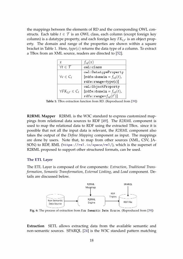
Fig. 6: The process of extraction from Non Semantic Data Source. (Reproduced from [39])
Extraction SETL allows extracting data from the available semantic andnon-semantic sources. SPARQL [24] is the W3C standard pattern matching
18
3. A Semantic ETL Framework for Semantic Data Warehouses
language for querying a semantic source. It uses SELECT queries to retrievedata and CONSTRUCT queries to produce an RDF graph (composed of a setof RDF triples). SETL applies SPARQL queries to a local RDF file or through aSPARQL endpoint to extract data from a semantic source. Figure 6 illustratesthe process of data extraction from a non-semantic source. There a semanticversion of the non-semantic source is created using an R2RML engine. AnR2RML engine takes a relational database and an R2RML mapping file asinput and generates an RDF dataset based on the mapping file [7]. Then,the RDF version of the non-semantic source can be queried using SPARQLqueries.
Once the data is extracted, the next task is to transform the extracteddata (given in the CSV format) according to the semantics encoded in thetarget TBox. SETL divides the transformation tasks into two components:Traditional Transformation and Semantic Transformation.
Traditional Transformation The Traditional Transformation component in-cludes operations from traditional ETL tools to performs the formatting andcleansing tasks. SETL considers the following transformation tasks: duplicatedata removal, data normalization, renaming attributes, recalculating data, in-tegrity constraints checking, data filtering, unique identifier generation, de-fault value handling, and sorting/grouping/summarizing data. This com-ponent outputs a set of tables, where each table corresponds to a conceptconstruct (e.g., an OWL class, an MD level, an MD cube/dataset) of the tar-get TBox, and the columns and records of each table represent the proper-ties/level attributes and instances of that concept.
_:Iri0
pro:generatedIRI
pro:sourcedataset
pro:originalIRI
rdf:type
http://extbi.lab.aau.dk/sdw/Recipient#291866http://sub/recipient#291866
https://data.farmsubsidy.org/ http://extbi.lab.aau.dk/sdw/Recipient
Fig. 7: An entry into the Provenance Graph. (Adopted from [39])
Semantic Transformation The Semantic Transformation component takes eachoutput table produced by the Traditional Transformation component and trans-forms it into RDF data with MD semantics. The process is described in Al-gorithm 1. The algorithm takes the following inputs: a table (table), thename of a column in table (resourceKey) to be used to uniquely identify each
19
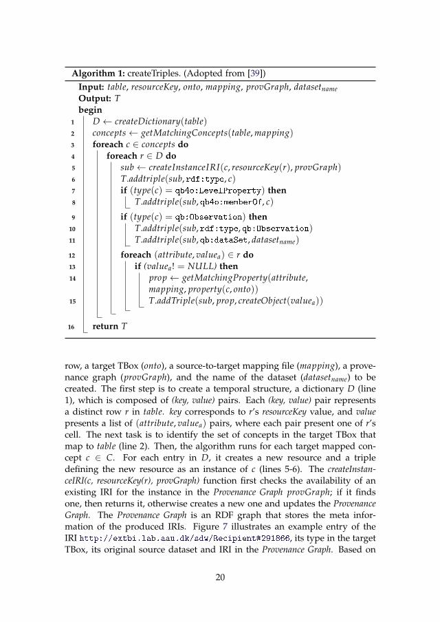
Algorithm 1: createTriples. (Adopted from [39])Input: table, resourceKey, onto, mapping, provGraph, datasetnameOutput: Tbegin
1 D ← createDictionary(table)2 concepts← getMatchingConcepts(table, mapping)3 foreach c ∈ concepts do4 foreach r ∈ D do5 sub← createInstanceIRI(c, resourceKey(r), provGraph)6 T.addtriple(sub, rdf:type, c)7 if (type(c) = qb4o:LevelProperty) then8 T.addtriple(sub, qb4o:memberOf, c)
9 if (type(c) = qb:Observation) then10 T.addtriple(sub, rdf:type, qb:Observation)11 T.addtriple(sub, qb:dataSet, datasetname)
12 foreach (attribute, valuea) ∈ r do13 if (valuea! = NULL) then14 prop← getMatchingProperty(attribute,
mapping, property(c, onto))15 T.addTriple(sub, prop, createObject(valuea))
16 return T
row, a target TBox (onto), a source-to-target mapping file (mapping), a prove-nance graph (provGraph), and the name of the dataset (datasetname) to becreated. The first step is to create a temporal structure, a dictionary D (line1), which is composed of (key, value) pairs. Each (key, value) pair representsa distinct row r in table. key corresponds to r’s resourceKey value, and valuepresents a list of (attribute, valuea) pairs, where each pair present one of r’scell. The next task is to identify the set of concepts in the target TBox thatmap to table (line 2). Then, the algorithm runs for each target mapped con-cept c ∈ C. For each entry in D, it creates a new resource and a tripledefining the new resource as an instance of c (lines 5-6). The createInstan-ceIRI(c, resourceKey(r), provGraph) function first checks the availability of anexisting IRI for the instance in the Provenance Graph provGraph; if it findsone, then returns it, otherwise creates a new one and updates the ProvenanceGraph. The Provenance Graph is an RDF graph that stores the meta infor-mation of the produced IRIs. Figure 7 illustrates an example entry of theIRI http://extbi.lab.aau.dk/sdw/Recipient#291866, its type in the targetTBox, its original source dataset and IRI in the Provenance Graph. Based on
20
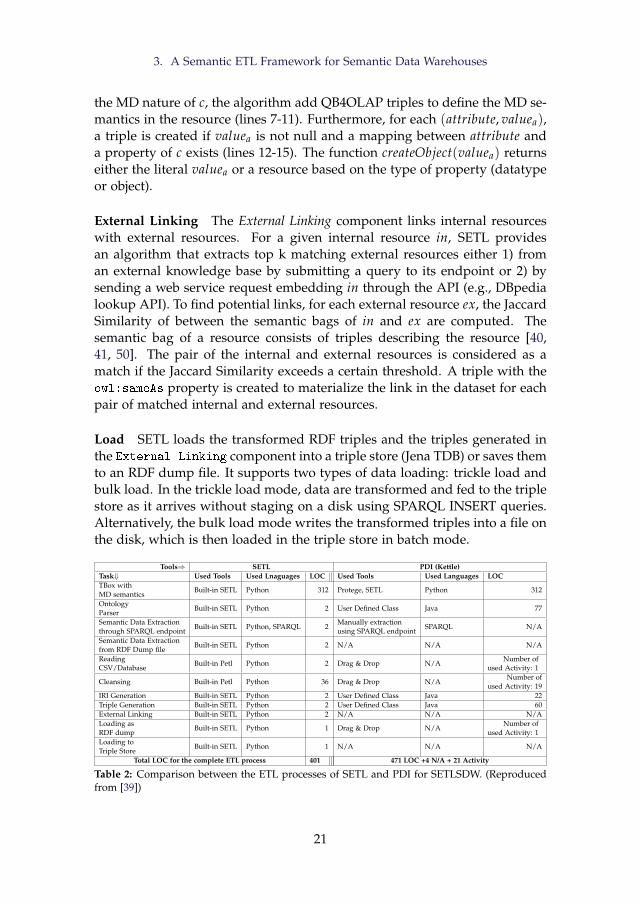
3. A Semantic ETL Framework for Semantic Data Warehouses
the MD nature of c, the algorithm add QB4OLAP triples to define the MD se-mantics in the resource (lines 7-11). Furthermore, for each (attribute, valuea),a triple is created if valuea is not null and a mapping between attribute anda property of c exists (lines 12-15). The function createObject(valuea) returnseither the literal valuea or a resource based on the type of property (datatypeor object).
External Linking The External Linking component links internal resourceswith external resources. For a given internal resource in, SETL providesan algorithm that extracts top k matching external resources either 1) froman external knowledge base by submitting a query to its endpoint or 2) bysending a web service request embedding in through the API (e.g., DBpedialookup API). To find potential links, for each external resource ex, the JaccardSimilarity of between the semantic bags of in and ex are computed. Thesemantic bag of a resource consists of triples describing the resource [40,41, 50]. The pair of the internal and external resources is considered as amatch if the Jaccard Similarity exceeds a certain threshold. A triple with theowl:sameAs property is created to materialize the link in the dataset for eachpair of matched internal and external resources.
Load SETL loads the transformed RDF triples and the triples generated inthe External Linking component into a triple store (Jena TDB) or saves themto an RDF dump file. It supports two types of data loading: trickle load andbulk load. In the trickle load mode, data are transformed and fed to the triplestore as it arrives without staging on a disk using SPARQL INSERT queries.Alternatively, the bulk load mode writes the transformed triples into a file onthe disk, which is then loaded in the triple store in batch mode.
Tools⇒ SETL PDI (Kettle)Task⇓ Used Tools Used Lnaguages LOC Used Tools Used Languages LOCTBox withMD semantics
Built-in SETL Python 312 Protege, SETL Python 312
OntologyParser
Built-in SETL Python 2 User Defined Class Java 77
Semantic Data Extractionthrough SPARQL endpoint
Built-in SETL Python, SPARQL 2Manually extractionusing SPARQL endpoint
SPARQL N/A
Semantic Data Extractionfrom RDF Dump file
Built-in SETL Python 2 N/A N/A N/A
ReadingCSV/Database
Built-in Petl Python 2 Drag & Drop N/ANumber of
used Activity: 1
Cleansing Built-in Petl Python 36 Drag & Drop N/ANumber of
used Activity: 19IRI Generation Built-in SETL Python 2 User Defined Class Java 22Triple Generation Built-in SETL Python 2 User Defined Class Java 60External Linking Built-in SETL Python 2 N/A N/A N/ALoading asRDF dump
Built-in SETL Python 1 Drag & Drop N/ANumber of
used Activity: 1Loading toTriple Store
Built-in SETL Python 1 N/A N/A N/A
Total LOC for the complete ETL process 401 471 LOC +4 N/A + 21 Activity
Table 2: Comparison between the ETL processes of SETL and PDI for SETLSDW. (Reproducedfrom [39])
21
3.5 Discussion
Each component of the SETL framework described in Section 3.3 is imple-mented using Python because it supports programmer productivity and hascomprehensive standard libraries. For the implementation details, readersare referred to Paper A [39]. SETL is compared to the state-of-the-art, namely,ExtBI [2] and Pentaho Data Integration (PDI) [9]. As discussed in Section 3.2,a knowledge base, SETLKB, is created using SETL, which is used to makea comprehensive comparison with the process used in ExtBI. Readers aredirected to Paper A [39] for the detailed experiment and evaluation. The fol-lowing are the main advantages of SETL compared to ExtBI. 1) SETL makesthe programmer more productive, as it uses only a fraction (570) of the Linesof Code (LOC) of 1879+5 N/A5(by ExtBI) to complete the ETL process. 2)SETL only requires programming in Python instead of 7 different languagesand tools. 3) The ETL process of SETL is run in a single pass, whereas ExtBIcould not run the ETL process in a single pass because of using differenttools and languages. 4) SETL produces a better knowledge base than theone produced by ExtBI in terms of consistency, completeness, and externallinking.
In the second step of the use case data integration, discussed in Sec-tion 3.2, an MD SDW is produced using SETL, and the process is comparedwith PDI. Table 2 summarizes the tools, languages, and the LOC used toprocess integration tasks by SETL and PDI 6. In total, PDI takes 471 LOC +4 N/A + 21 Activity7 to run the ETL process, whereas SETL takes only 401LOC to run the complete ETL process. Hence, SETL creates an MD SDWwith less number of LOC, user interactions than PDI where a user requiresto build their own Java class, plugins, and manual tasks to enable semanticintegration. As PDI does not allow all tasks related to semantic integration, apart of the ETL process generated by SETL is compared with PDI (Details arein [39]). SETL takes only 1644 seconds, where PDI takes 1903 seconds. Thus,SETL is 13.5% faster than PDI.
In summary, this chapter proposes a semantic ETL Framework to inte-grate semantic and non-semantic data sources. The experiments show thatthe programmable framework performs better in terms of programmer pro-ductivity, knowledge base quality, and performance. However, to use it, auser requires a programming background. Although it enables to create anETL flow and provides methods by combining several tasks, there is a lackof a well-defined set of basic semantic ETL operators that allow users morecontrol in creating their ETL process. Moreover, how to update the SDW to
5An N/A (Not Available) indicates that the task is done by either user interactions or man-ually or is not supported by the process. Therefore, the LOC cannot be counted.
6https://github.com/pentaho7An activity is an operation directly supported by PDI with a drag and drop facility
22
4. High-Level ETL Constructs for Processing Semantic Data
synchronize it with the changes taking place in the sources is not discussed.Further, in a data lake /big data environment, the data may come from het-erogeneous formats, and the use of the relational model as the canonicalmodel may generate an overhead. Transforming JSON or XML data to rela-tional to finally generate RDF can be avoided by using RDF as the canonicalmodel instead. Further, several works have discussed the appropriateness ofknowledge graphs for data integration purposes and, specifically, as a canon-ical data model [12]. An additional benefit of using RDF as a canonical modelis that it allows adding semantics without being compliant to a fixed schema.
In Sections 4 and 5, the limitations identified in this discussion will befurther elaborated. Specifically, Section 4 presents a set of semantic ETL oper-ators that can be used to generate semantically rich and complex ETL flows.Doing so, the focus of the research moves from programmatic functions inPython to orchestrating high-level operators. These operators are further de-signed to use RDF as the canonical model. Also, some additional tasks tofacilitate SDW management are introduced, such as the update of dimen-sional data to adapt to changes in the sources. In Section 5, a tool to performhigh-level OLAP operations on top of an SDW is presented. This way, theuser does not need to implement OLAP queries by means of SPARQL andcan directly use operators such as roll-up or drill-down.
4 High-Level ETL Constructs for Processing Seman-tic Data
This section is a summary of Paper B [17].
4.1 Motivation and Problem Statement
Since there are a number of available RDF wrappers that can translate non-semantic resources to semantic resources, this section focuses on processingsemantic sources and the usage of the RDF model as the canonical model inthe integration process. The rest of this section explains the improvementsintroduced on top of SETL to remedy its main drawbacks identified in Sec-tion 3.5. Although SETL integrates semantic and non-semantic data sources,however, a set of high-level ETL constructs (tasks/operations) required toprocess semantic data is missing. As a consequence, in SETL, an ETL de-signer has to create specific handcode modules to deal with semantic data.Moreover, the output of the Define Mapping component in Figure 4 does notrepresent the complete scenario of the integration process, i.e., a mapping fileneeds to be separately created for each extraction and transformation mod-ule. Furthermore, there is a need to update the SDW to reflect the changesthat occur in the sources over time. Finally, SETL is developed in Python
23
and requires a programming background to accomplish the integration tasks.Therefore, users with no programming knowledge cannot use SETL.
Paper B defines the integration process based on two layers: the Definitionand the Execution Layer and a set of high-level ETL constructs (tasks/oper-ations) for each layer, with the aim of overcoming the drawbacks identifiedabove for SETL. Different to SETL or other ETL tools, a new paradigm is pro-posed: the ETL flow transformations are characterized at the Definition Layerinstead of independently within each ETL operation (in the Execution Layer).This is done by generating a mapping file that gives an overall view of theintegration process. This mapping file is our primary metadata source andwill be read by the ETL operations, orchestrated in the ETL flow (ExecutionLayer), to parametrize themselves. Thus, we are centralizing the creation ofthe required metadata to automate the ETL process in the Definition layer.
To create the mapping file, we use our proposed source-to-target mapping(S2TMAP) vocabulary. Besides other MD transformation operations, Paper Balso proposes an ETL operation that allows applying three types of dimen-sion updates (Type 1, Type 2, and Type 3) to accommodate evolution in anSDW, which were defined by Ralph Kimball in [34]. Furthermore, an ETLoperation to extract a TBox from a semantic source defined without schemais also presented. Most importantly, an algorithm to automatically generateETL data flows from the mappings file is proposed. Finally, a GUI-basedprototype, named SETLCONSTRUCT , based on the innovative elements men-tioned above, is introduced. Hence, developers with no programming back-ground can accomplish the integration tasks by interacting with the system’sinterfaces. Moreover, developers can create ETL flows either manually usingdrag-n-drop options or automatically using the auto ETL feature. The follow-ing sections present the overview of the integration process, the componentdescription of each layer, and an overall discussion.
4.2 Layer-Based Semantic Data Integration Process
As discussed in Section 3.3, this thesis focuses on the data integration step(step 2) of a demand-driven approach. Here, we introduce a two-layered in-tegration process. In the Definition Layer, a single source of metadata truthis defined. This includes: the target SDW, semantic representation of thesource schemas, and a source to target mapping file. Relevantly, the meta-data created represents the ETL flow at the schema level. In the ExecutionLayer, ETL data flows based on high-level operations are created. This layerexecutes the ETL data flows for instances (i.e., at the data level). Movingback to a kind of algebraic view of the ETL process gives freedom to the userto express richer and complex flows. Importantly, the ETL operations willread the metadata created and parameterize themselves automatically. Addi-tionally, the Execution Layer automatically checks the correctness of the flow
24
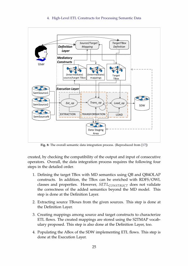
4. High-Level ETL Constructs for Processing Semantic Data
Load_op
EXTRACTION LOAD
Ext_opExt_op Trans_op
Source2TargetMapping
Source2TargetMapping
TargetTBoxDefinition
TargetTBoxDefinition
TRANSFORMATION
Execution Layer
Definition Layer
User
SemSourceNSemSourceN
SemSource1SemSource1
SemSource2SemSource2
Data Staging Area
Data Staging Area
SDWSDW
Mediatory Constructs
Fig. 8: The overall semantic data integration process. (Reproduced from [17])
created, by checking the compatibility of the output and input of consecutiveoperators. Overall, the data integration process requires the following foursteps in the detailed order.
1. Defining the target TBox with MD semantics using QB and QB4OLAPconstructs. In addition, the TBox can be enriched with RDFS/OWLclasses and properties. However, SETLCONSTRUCT does not validatethe correctness of the added semantics beyond the MD model. Thisstep is done at the Definition Layer.
2. Extracting source TBoxes from the given sources. This step is done atthe Definition Layer.
3. Creating mappings among source and target constructs to characterizeETL flows. The created mappings are stored using the S2TMAP vocab-ulary proposed. This step is also done at the Definition Layer, too.
4. Populating the ABox of the SDW implementing ETL flows. This step isdone at the Execution Layer.
25
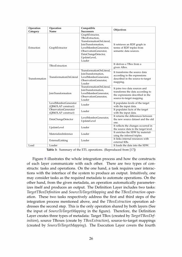
OperationCategory
OperationName
CompatibleSuccessors
Objectives
Extraction GraphExtractor
GraphExtractor,TBoxExtraction,TransformationOnLiteral,JoinTransformation,LevelMemberGenerator,ObservationGenerator,DataChangeDetector,UpdateLevel,Loader
It retrieves an RDF graph interms of RDF triples fromsemantic data sources.
Transformation
TBoxExtractionIt derives a TBox from agiven ABox.
TransformationOnLiteral
TransformationOnLiteral,JoinTransformation,LevelMemberGenerator,ObservationGenerator,Loader
It transforms the source dataaccording to the expressionsdescribed in the source-to-targetmapping.
JoinTransformation
TransformationOnLiteral,JoinTransformation,LevelMemberGenerator,ObservationGenerator,Loader
It joins two data sources andtransforms the data according tothe expressions described in thesource-to-target mapping.
LevelMemberGenerator(QB4OLAP construct)
LoaderIt populates levels of the targetwith the input data.
ObservationGenerator(QB4OLAP construct)
LoaderIt populates facts of the targetwith the input data.
DataChangeDetectorLevelMemberGenerator,UpdateLevel
It returns the differences betweenthe new source dataset and the oldone.
UpdateLevel LoaderIt reflects the changes occurred inthe source data to the target level.
MaterializeInference LoaderIt enriches the SDW by material-izing the inferred triples.
ExternalLinking LoaderIt links internal resources withexternal KBs.
Load Loader It loads the data into the SDW.
Table 3: Summary of the ETL operations. (Reproduced from [17])
Figure 8 illustrates the whole integration process and how the constructsof each layer communicate with each other. There are two types of con-structs: tasks and operations. On the one hand, a task requires user interac-tions with the interface of the system to produce an output. Intuitively, onemay consider tasks as the required metadata to automate operations. On theother hand, from the given metadata, an operation automatically parameter-izes itself and produces an output. The Definition Layer includes two tasks:TargetTBoxDefinition and SourceToTargetMapping and the TBoxExtraction oper-ation. These two tasks respectively address the first and third steps of theintegration process mentioned above, and the TBoxExtraction operation ad-dresses the second step. This is the only operation shared by both layers (Seethe input of SourceToTargetMapping in the figure). Therefore, the DefinitionLayer creates three types of metadata: Target TBox (created by TargetTBoxDef-inition), source TBoxes (create by TBoxExtraction), source-to-target mappings(created by SourceToTargetMapping). The Execution Layer covers the fourth
26
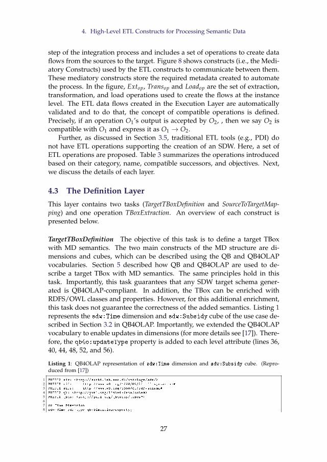
4. High-Level ETL Constructs for Processing Semantic Data
step of the integration process and includes a set of operations to create dataflows from the sources to the target. Figure 8 shows constructs (i.e., the Medi-atory Constructs) used by the ETL constructs to communicate between them.These mediatory constructs store the required metadata created to automatethe process. In the figure, Extop, Transop and Loadop are the set of extraction,transformation, and load operations used to create the flows at the instancelevel. The ETL data flows created in the Execution Layer are automaticallyvalidated and to do that, the concept of compatible operations is defined.Precisely, if an operation O1’s output is accepted by O2, , then we say O2 iscompatible with O1 and express it as O1 → O2.
Further, as discussed in Section 3.5, traditional ETL tools (e.g., PDI) donot have ETL operations supporting the creation of an SDW. Here, a set ofETL operations are proposed. Table 3 summarizes the operations introducedbased on their category, name, compatible successors, and objectives. Next,we discuss the details of each layer.
4.3 The Definition Layer
This layer contains two tasks (TargetTBoxDefinition and SourceToTargetMap-ping) and one operation TBoxExtraction. An overview of each construct ispresented below.
TargetTBoxDefinition The objective of this task is to define a target TBoxwith MD semantics. The two main constructs of the MD structure are di-mensions and cubes, which can be described using the QB and QB4OLAPvocabularies. Section 5 described how QB and QB4OLAP are used to de-scribe a target TBox with MD semantics. The same principles hold in thistask. Importantly, this task guarantees that any SDW target schema gener-ated is QB4OLAP-compliant. In addition, the TBox can be enriched withRDFS/OWL classes and properties. However, for this additional enrichment,this task does not guarantee the correctness of the added semantics. Listing 1represents the sdw:Time dimension and sdw:Subsidy cube of the use case de-scribed in Section 3.2 in QB4OLAP. Importantly, we extended the QB4OLAPvocabulary to enable updates in dimensions (for more details see [17]). There-fore, the qb4o:updateType property is added to each level attribute (lines 36,40, 44, 48, 52, and 56).
Listing 1: QB4OLAP representation of sdw:Time dimension and sdw:Subsidy cube. (Repro-duced from [17])
1 PREFIX sdw: <http :// extbi.lab.aau.dk/ontology/sdw/>
2 PREFIX rdf: http :// www.w3.org /1999/02/22 -rdf -syntax -ns#
3 PREFIX rdfs: http ://www.w3.org /2000/01/ rdf -schema#
4 PREFIX qb: <http :// purl.org/linked -data/cube#>
5 PREFIX qb4o: <http :// purl.org/qb4olap/cubes#>
67 ## Time Dimension
8 sdw:Time rdf:type qb:DimensionProperty;
27
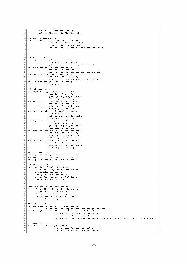
9 rdfs:label "Time Dimension";
10 qb4o:hasHierarcy sdw:TimeHierarchy.
1112 # Dimension Hierarchies
13 sdw:TimeHierarchy rdf:type qb4o:Hierarchy;
14 rdfs:label "Time Hierarchy";
15 qb4o:inDimension sdw:Time;
16 qb4o:hasLevel sdw:Day , sdw:Month , sdw:Year.
17181920 # Hierarchy levels
21 sdw:Day rdf:type qb4o:LevelProperty;
22 rdfs:label "Day Level";
23 qb4o:hasAttribute sdw:dayId , sdw:dayName.
24 sdw:Month rdf:type qb4o:LevelProperty;
25 rdfs:label "Month Level";
26 qb4o:hasAttribute sdw:monthId , sdw:monthName.
27 sdw:Year rdf:type qb4o:LevelProperty;
28 rdfs:label "Year Level";
29 qb4o:hasAttribute sdw:yearId , sdw:yearName.
30 sdw:All rdf:type qb4o:LevelProperty;
31 rdfs:label "ALL".
3233 # Level attributes
34 sdw:dayId rdf:type qb4o:LevelAttribute;
35 rdfs:label "day ID";
36 qb4o:updateType qb4o:Type2;
37 rdfs:range xsd:String.
38 sdw:monthId rdf:type qb4o:LevelAttribute;
39 rdfs:label "Month ID";
40 qb4o:updateType qb4o:Type2;
41 rdfs:range xsd:String.
42 sdw:yearId rdf:type qb4o:LevelAttribute;
43 rdfs:label "year ID";
44 qb4o:updateType qb4o:Type2;
45 rdfs:range xsd:String.
46 sdw:dayName rdf:type qb4o:LevelAttribute;
47 rdfs:label "day Name";
48 qb4o:updateType qb4o:Type1;
49 rdfs:range xsd:String.
50 sdw:monthName rdf:type qb4o:LevelAttribute;
51 rdfs:label "Month Name";
52 qb4o:updateType qb4o:Type1;
53 rdfs:range xsd:String.
54 sdw:yearName rdf:type qb4o:LevelAttribute;
55 rdfs:label "year Name";
56 qb4o:updateType qb4o:Type1;
57 rdfs:range xsd:String.
5859 #rollup relations
60 sdw:payMonth rdf:type qb4o:RollupProperty.
61 sdw:payYear rdf:type qb4o:RollupProperty.
62 sdw:payAll rdf:type qb4o:RollupProperty.
6364 # Hierarchy Steps
65 _:ht1 rdf:type qb4o:HierarchyStep;
66 qb4o:inHierarchy sdw:TimeHierarchy;
67 qb4o:childLevel sdw:Day;
68 qb4o:parentLevel sdw:Month;
69 qb4o:pcCardinality qb4o:OneToMany;
70 qb4o:rollup sdw:payMonth.
717273 _:ht2 rdf:type qb4o:HierarchyStep;
74 qb4o:inHierarchy sdw:TimeHierarchy;
75 qb4o:childLevel sdw:Month;
76 qb4o:parentLevel sdw:Year;
77 qb4o:pcCardinality qb4o:OneToMany;
78 qb4o:rollup sdw:payYear.
7980 ## Subsidy Cube
81 sdw:amounteuro rdf:type qb:MeasureProperty;
82 rdfs:label "subsidy amount"; rdfs:range xsd:Double.
83 sdw:SubsidyStructure rdf:type qb:DataStructureDefinition;
84 qb:component[qb4o:level sdw:Recipient ];
85 qb:component[qb4o:level sdw:Day];
86 qb:component[qb:measure sdw:amounteuro; qb4o:aggregateFunction qb4o:sum , qb4o:avg].
8788 # Subsidy Dataset
89 sdw:Subsidy rdf:type qb:Dataset;
90 rdfs:label "Subsidy dataset";
91 qb:structure sdw:SubsidyStructure;
28
4. High-Level ETL Constructs for Processing Semantic Data
TBoxExtraction After defining a target TBox, the next step is to extractsource TBoxes. Typically, in a semantic source, the TBox and ABox of thesource are provided. Therefore, no external extraction task/operation is re-quired. However, sometimes, the source contains only the ABox, and noTBox. In that scenario, an extraction process is required to derive a TBoxfrom the ABox. We formally present the TBox extraction operation from agiven ABox ABox as fABox2TBox : ABox → TBox. The derived TBox is de-fined in terms of the following TBox constructs: A set of concepts C, a set ofconcept taxonomies H, a set of properties P, and the sets of property domains(D) and ranges (R). The following steps describe the process to derive eachTBox element for TBox.
1. C: By checking the unique objects of the triples in ABox where rdf:type
is used as a predicate, C is identified.
2. H: The taxonomies among concepts are identified by checking the in-stances they share among themselves. Let C1 and C2 be two concepts.One of the following taxonomic relationships holds between them: 1)if C1 contains all instances of C2, then we say C2 is a subclass of C1 (C2rdfs:subClassOf C1); 2) if they do not share any instances, they aredisjoint (C1 owl:disjointWith C2); and 3) if C1 and C2 are both a sub-class of each other, then they are equivalent (C1 owl:equivalentClass
C2).
3. P, D, R: By checking the unique predicates of the triples, P is derived.A property p ∈ P can relate resources with either resources or literals.If the objects of the triples where p is used as predicates are IRIs, thenp is an object property; the domain of p is the set of the types of thesubjects of those triples, and the range of p is the types of the objects ofthose triples. If the objects of the triples where p is used as predicatesare literals, then p is a datatype property; the domain of p is the set oftypes the subjects of those triples, and the range is the set of data typesof the literals.
SourceToTargetMapping Once the target and source TBoxes are defined, thenext task is to characterize the ETL flows at the Definition Layer by creatingsource-to-target mappings. Because of the heterogeneous nature of sourcedata, mappings among sources and the target should be done at the TBoxlevel. In principle, mappings are constructed between sources and the tar-get; however, since mappings can get very complicated, we allow to createa sequence of SourceToTargetMappings whose subsequent input is generatedby the precedent operation. The communication between these operations isby means of a materialized intermediate mapping definition and its meant to
29
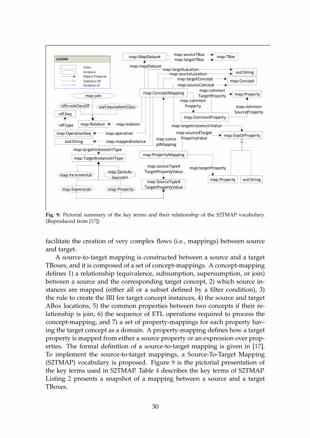
map:MapDataset
rdfs:subClassOf
map:ConceptMapping
map:PropertyMapping
map:TBox
xsd:String
map:Concept
map:Relation
xsd:String
map:TargetInstanceIriType
map:Property
map:ExpOrProperty
owl:equivalentClass
map:join
map:Property
map:Incremental
map:Expression
map:SameAsSourceIri
map:SourceType4TargetPropertyValue
map:sourceType4TargetPropertyValue
map:source4TargetPropertyValue
map:targetInstanceIriValue
map:mapDataset
map:OperationSeq
map:Property
map:targetInstanceIriType
map:targetProperty
map:mappedInstance
map:operation
map:relation
LEGEND
Class
InstanceObject Property
SubClass OfInstance of
LEGEND
Class
InstanceObject Property
SubClass OfInstance of
map:conceptMapping
rdf:Seq
rdf:type
xsd:Stringmap:sourceLocationmap:targetLocation
map:targetTBoxmap:sourceTBox
map:targetConcept
map:sourceConcept
map:CommonProperty
map:commonSourceProperty
map:commonTargetProperty
map:commonProperty
Fig. 9: Pictorial summary of the key terms and their relationship of the S2TMAP vocabulary.(Reproduced from [17])
facilitate the creation of very complex flows (i.e., mappings) between sourceand target.
A source-to-target mapping is constructed between a source and a targetTBoxes, and it is composed of a set of concept-mappings. A concept-mappingdefines 1) a relationship (equivalence, subsumption, supersumption, or join)between a source and the corresponding target concept, 2) which source in-stances are mapped (either all or a subset defined by a filter condition), 3)the rule to create the IRI for target concept instances, 4) the source and targetABox locations, 5) the common properties between two concepts if their re-lationship is join, 6) the sequence of ETL operations required to process theconcept-mapping, and 7) a set of property-mappings for each property hav-ing the target concept as a domain. A property-mapping defines how a targetproperty is mapped from either a source property or an expression over prop-erties. The formal definition of a source-to-target mapping is given in [17].To implement the source-to-target mappings, a Source-To-Target Mapping(S2TMAP) vocabulary is proposed. Figure 9 is the pictorial presentation ofthe key terms used in S2TMAP. Table 4 describes the key terms of S2TMAP.Listing 2 presents a snapshot of a mapping between a source and a targetTBoxes.
30
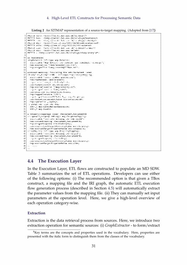
4. High-Level ETL Constructs for Processing Semantic Data
Listing 2 An S2TMAP representation of a source-to-target mapping. (Adopted from [17])
1 PREFIX onto: <http :// extbi.lab.aau.dk/ontology/>
2 PREFIX bus: <http :// extbi.lab.aau.dk/ontology/business/>
3 PREFIX sub: <http :// extbi.lab.aau.dk/ontology/subsidy/>
4 PREFIX rdf: <http :// www.w3.org /1999/02/22 -rdf -syntax -ns#>
5 PREFIX rdfs: <http ://www.w3.org /2000/01/ rdf -schema#>
6 PREFIX map: <http :// extbi.lab.aau.dk/ontology/s2tmap/>
7 PREFIX sdw: <http :// extbi.lab.aau.dk/sdw >
8 PREFIX : <http :// extbi.lab.aau.dk/ontology/s2map/example#>
910 ## MapDataset
11 :mapDataset1 rdf:type map:Dataset;
12 rdfs:label "Map -dataset for subsidy and subsidyMD ontology";
13 map:sourceTBox "/map/subsidyTBox.ttl";
14 map:targetTBox "/map/subsidyMDTBox.ttl".
1516 #concept -mapping: Populating the sdw:Recipient level
17 :Recipient_RecipientMD rdf:type map:ConceptMapping;
18 rdfs:label "Level member generation";
19 map:mapDataset :mapDataset1;
20 map:sourceConcept sub:Recipient;
21 map:targetConcept sdw:Recipient;
22 map:sourceLocation "/map/subsidy.nt";
23 map:targetLocation "/map/sdw";
24 map:relation owl:equivalentClass;
25 map:mappedInstance "All";
26 map:targetInstanceIRIValueType map:Property;
27 map:targetInstanceIRIValue sub:recipientID;
28 map:operation _:opSeq1.
29 _:opSeq1 rdf:type rdf:Seq;
30 rdf:_1 map:LevelMemberGenerator;
31 rdf:_2 map:Loader.
3233 # property -mappings under :Recipient_RecipientMD
34 :companyId_company rdf:type map:PropertyMapping;
35 rdfs:label "property -mapping for companyId";
36 map:conceptMapping :Recipient_RecipientMD;
37 map:targetProperty sdw:hasCompany;
38 map:sourceType4TargetPropertyValue map:Property;
39 map:source4TargetPropertyValue sub:companyId;
40 :cityId_city rdf:type map:PropertyMapping;
41 rdfs:label "property -mapping for cityId";
42 map:conceptMapping :Recipient_RecipientMD;
43 map:targetProperty sdw:inCity;
44 map:sourceType4TargetPropertyValue map:Property;
45 map:source4TargetPropertyValue sub:city;
46 ..........
47 ..
4.4 The Execution Layer
In the Execution Layer, ETL flows are constructed to populate an MD SDW.Table 3 summarizes the set of ETL operations. Developers can use eitherof the following options: (i) The recommended option is that given a TBoxconstruct, a mapping file and the IRI graph, the automatic ETL executionflow generation process (described in Section 4.5) will automatically extractthe parameter values from the mapping file. (ii) They can manually set inputparameters at the operation level. Here, we give a high-level overview ofeach operation category-wise.
Extraction
Extraction is the data retrieval process from sources. Here, we introduce twoextraction operation for semantic sources: (i) GraphExtractor - to form/extract
8Key terms are the concepts and properties used in the vocabulary. Here, properties arepresented with the italic form to distinguish them from the classes of the vocabulary.
31
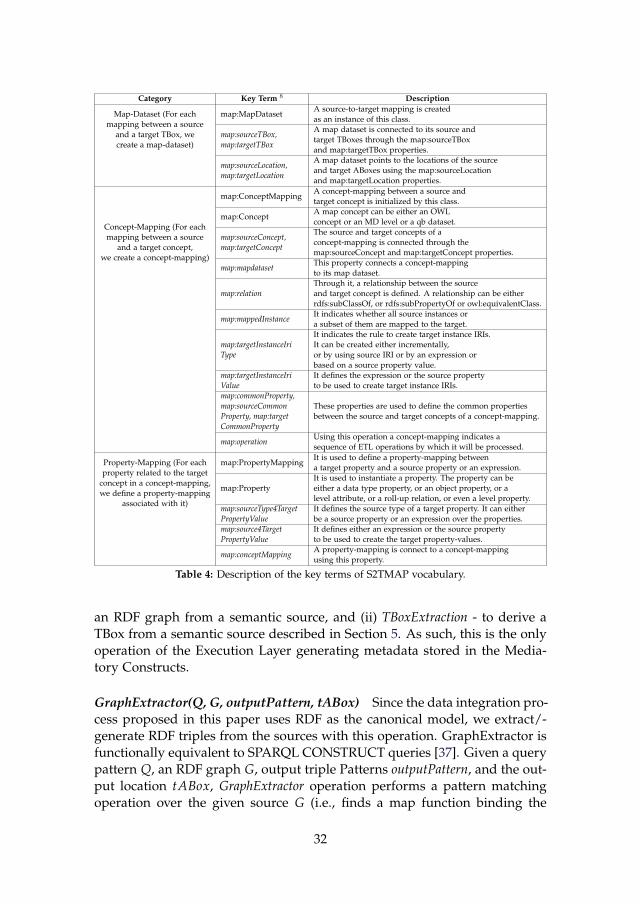
Category Key Term 8 Description
Map-Dataset (For eachmapping between a source
and a target TBox, wecreate a map-dataset)
map:MapDatasetA source-to-target mapping is createdas an instance of this class.
map:sourceTBox,map:targetTBox
A map dataset is connected to its source andtarget TBoxes through the map:sourceTBoxand map:targetTBox properties.
map:sourceLocation,map:targetLocation
A map dataset points to the locations of the sourceand target ABoxes using the map:sourceLocationand map:targetLocation properties.
Concept-Mapping (For eachmapping between a source
and a target concept,we create a concept-mapping)
map:ConceptMappingA concept-mapping between a source andtarget concept is initialized by this class.
map:ConceptA map concept can be either an OWLconcept or an MD level or a qb dataset.
map:sourceConcept,map:targetConcept
The source and target concepts of aconcept-mapping is connected through themap:sourceConcept and map:targetConcept properties.
map:mapdatasetThis property connects a concept-mappingto its map dataset.
map:relationThrough it, a relationship between the sourceand target concept is defined. A relationship can be eitherrdfs:subClassOf, or rdfs:subPropertyOf or owl:equivalentClass.
map:mappedInstanceIt indicates whether all source instances ora subset of them are mapped to the target.
map:targetInstanceIriType
It indicates the rule to create target instance IRIs.It can be created either incrementally,or by using source IRI or by an expression orbased on a source property value.
map:targetInstanceIriValue
It defines the expression or the source propertyto be used to create target instance IRIs.
map:commonProperty,map:sourceCommonProperty, map:targetCommonProperty
These properties are used to define the common propertiesbetween the source and target concepts of a concept-mapping.
map:operationUsing this operation a concept-mapping indicates asequence of ETL operations by which it will be processed.
Property-Mapping (For eachproperty related to the target
concept in a concept-mapping,we define a property-mapping
associated with it)
map:PropertyMappingIt is used to define a property-mapping betweena target property and a source property or an expression.
map:PropertyIt is used to instantiate a property. The property can beeither a data type property, or an object property, or alevel attribute, or a roll-up relation, or even a level property.
map:sourceType4TargetPropertyValue
It defines the source type of a target property. It can eitherbe a source property or an expression over the properties.
map:source4TargetPropertyValue
It defines either an expression or the source propertyto be used to create the target property-values.
map:conceptMappingA property-mapping is connect to a concept-mappingusing this property.
Table 4: Description of the key terms of S2TMAP vocabulary.
an RDF graph from a semantic source, and (ii) TBoxExtraction - to derive aTBox from a semantic source described in Section 5. As such, this is the onlyoperation of the Execution Layer generating metadata stored in the Media-tory Constructs.
GraphExtractor(Q, G, outputPattern, tABox) Since the data integration pro-cess proposed in this paper uses RDF as the canonical model, we extract/-generate RDF triples from the sources with this operation. GraphExtractor isfunctionally equivalent to SPARQL CONSTRUCT queries [37]. Given a querypattern Q, an RDF graph G, output triple Patterns outputPattern, and the out-put location tABox, GraphExtractor operation performs a pattern matchingoperation over the given source G (i.e., finds a map function binding the
32
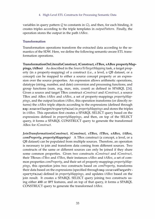
4. High-Level ETL Constructs for Processing Semantic Data
variables in query pattern Q to constants in G), and then, for each binding, itcreates triples according to the triple templates in outputPattern. Finally, theoperation stores the output in the path tABox.
Transformation
Transformation operations transform the extracted data according to the se-mantics of the SDW. Here, we define the following semantic-aware ETL trans-formation operations.
TransformationOnLiteral(sConstruct, tConstruct, sTBox, sABox propertyMap-pings, tABox) As described in the SourceToTargetMapping task, a target prop-erty (in a property-mapping) of a construct (i.e., a level, a QB dataset, or aconcept) can be mapped to either a source concept property or an expres-sion over the source properties. An expression allows arithmetic operations,datatype (string, number, and date) conversion and processing functions, andgroup functions (sum, avg, max, min, count) as defined in SPARQL [24].Given a source and target TBox construct sConstruct and tConstruct, a sourceTBox and ABox tABox and sABox, a set of property-mappings propertyMap-pings, and the output location tABox, this operation transforms (or directly re-turns) the sABox triple objects according to the expressions (defined throughmap:source4TargetPropertyValue) in propertyMappings and stores the triplesin tABox. This operation first creates a SPARQL SELECT query based on theexpressions defined in propertyMappings, and then, on top of the SELECTquery, it forms a SPARQL CONSTRUCT query to generate the transformedABox for tConstruct.
JoinTransformation(sConstruct, tConstruct, sTBox, tTBox, sABox, tABox,comProperty, propertyMappings) A TBox construct (a concept, a level, or aQB dataset) can be populated from multiple sources. Therefore, an operationis necessary to join and transform data coming from different sources. Twoconstructs of the same or different sources can only be joined if they sharesome common properties. Given two constructs sConstruct and tConstruct,their TBoxes sTBox and tTBox, their instances sABox and tABox, a set of com-mon properties comProperty, and their set of property-mappings propertyMap-pings, this operation joins two constructs based on comProperty, transformstheir data based on the expressions (specified through map:source4TargetPr-
opertyValue) defined in propertyMappings, and updates tABox based on thejoin result. It creates a SPARQL SELECT query joining two constructs us-ing either AND or OPT features, and on top of that query, it forms a SPARQLCONSTRUCT query to generate the transformed tABox.
33
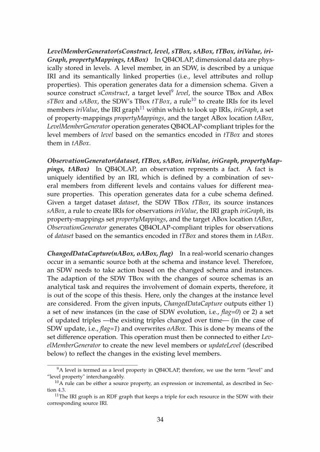
LevelMemberGenerator(sConstruct, level, sTBox, sABox, tTBox, iriValue, iri-Graph, propertyMappings, tABox) In QB4OLAP, dimensional data are phys-ically stored in levels. A level member, in an SDW, is described by a uniqueIRI and its semantically linked properties (i.e., level attributes and rollupproperties). This operation generates data for a dimension schema. Given asource construct sConstruct, a target level9 level, the source TBox and ABoxsTBox and sABox, the SDW’s TBox tTBox, a rule10 to create IRIs for its levelmembers iriValue, the IRI graph11 within which to look up IRIs, iriGraph, a setof property-mappings propertyMappings, and the target ABox location tABox,LevelMemberGenerator operation generates QB4OLAP-compliant triples for thelevel members of level based on the semantics encoded in tTBox and storesthem in tABox.
ObservationGenerator(dataset, tTBox, sABox, iriValue, iriGraph, propertyMap-pings, tABox) In QB4OLAP, an observation represents a fact. A fact isuniquely identified by an IRI, which is defined by a combination of sev-eral members from different levels and contains values for different mea-sure properties. This operation generates data for a cube schema defined.Given a target dataset dataset, the SDW TBox tTBox, its source instancessABox, a rule to create IRIs for observations iriValue, the IRI graph iriGraph, itsproperty-mappings set propertyMappings, and the target ABox location tABox,ObservationGenerator generates QB4OLAP-compliant triples for observationsof dataset based on the semantics encoded in tTBox and stores them in tABox.
ChangedDataCapture(nABox, oABox, flag) In a real-world scenario changesoccur in a semantic source both at the schema and instance level. Therefore,an SDW needs to take action based on the changed schema and instances.The adaption of the SDW TBox with the changes of source schemas is ananalytical task and requires the involvement of domain experts, therefore, itis out of the scope of this thesis. Here, only the changes at the instance levelare considered. From the given inputs, ChangedDataCapture outputs either 1)a set of new instances (in the case of SDW evolution, i.e., flag=0) or 2) a setof updated triples —the existing triples changed over time— (in the case ofSDW update, i.e., flag=1) and overwrites oABox. This is done by means of theset difference operation. This operation must then be connected to either Lev-elMemberGenerator to create the new level members or updateLevel (describedbelow) to reflect the changes in the existing level members.
9A level is termed as a level property in QB4OLAP, therefore, we use the term “level" and“level property" interchangeably.
10A rule can be either a source property, an expression or incremental, as described in Sec-tion 4.3.
11The IRI graph is an RDF graph that keeps a triple for each resource in the SDW with theircorresponding source IRI.
34
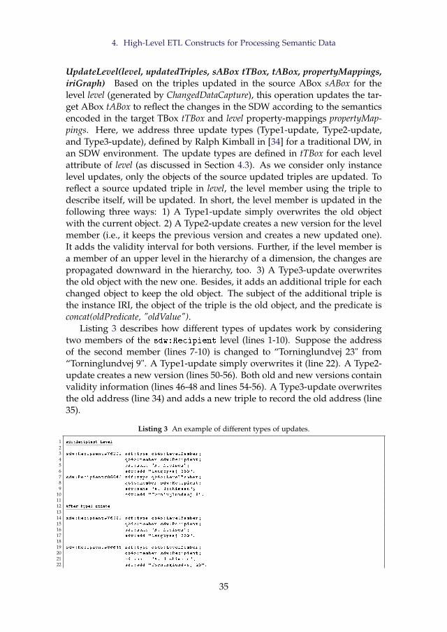
4. High-Level ETL Constructs for Processing Semantic Data
UpdateLevel(level, updatedTriples, sABox tTBox, tABox, propertyMappings,iriGraph) Based on the triples updated in the source ABox sABox for thelevel level (generated by ChangedDataCapture), this operation updates the tar-get ABox tABox to reflect the changes in the SDW according to the semanticsencoded in the target TBox tTBox and level property-mappings propertyMap-pings. Here, we address three update types (Type1-update, Type2-update,and Type3-update), defined by Ralph Kimball in [34] for a traditional DW, inan SDW environment. The update types are defined in tTBox for each levelattribute of level (as discussed in Section 4.3). As we consider only instancelevel updates, only the objects of the source updated triples are updated. Toreflect a source updated triple in level, the level member using the triple todescribe itself, will be updated. In short, the level member is updated in thefollowing three ways: 1) A Type1-update simply overwrites the old objectwith the current object. 2) A Type2-update creates a new version for the levelmember (i.e., it keeps the previous version and creates a new updated one).It adds the validity interval for both versions. Further, if the level member isa member of an upper level in the hierarchy of a dimension, the changes arepropagated downward in the hierarchy, too. 3) A Type3-update overwritesthe old object with the new one. Besides, it adds an additional triple for eachchanged object to keep the old object. The subject of the additional triple isthe instance IRI, the object of the triple is the old object, and the predicate isconcat(oldPredicate, "oldValue").
Listing 3 describes how different types of updates work by consideringtwo members of the sdw:Recipient level (lines 1-10). Suppose the addressof the second member (lines 7-10) is changed to “Torninglundvej 23" from“Torninglundvej 9". A Type1-update simply overwrites it (line 22). A Type2-update creates a new version (lines 50-56). Both old and new versions containvalidity information (lines 46-48 and lines 54-56). A Type3-update overwritesthe old address (line 34) and adds a new triple to record the old address (line35).
Listing 3 An example of different types of updates.
1 sdw:Recipient Level
23 sdw:Recipient #76291 rdf:type qb4o:LevelMember;
4 qb4o:member sdw:Recipient;
5 sdw:name "R. Nielsen";
6 sdw:add "Lyngbyvej 369".
7 sdw:Recipient #86646 rdf:type qb4o:LevelMember;
8 qb4o:member sdw:Recipient;
9 sdw:name "A. Jochimsen";
10 sdw:add "Torninglundvej 9".
1112 After type1 update
1314 sdw:Recipient #76291 rdf:type qb4o:LevelMember;
15 qb4o:member sdw:Recipient;
16 sdw:name "R. Nielsen";
17 sdw:add "Lyngbyvej 369".
1819 sdw:Recipient #86646 rdf:type qb4o:LevelMember;
20 qb4o:member sdw:Recipient;
21 sdw:name "A. Jochimsen";
22 sdw:add "Torninglundvej 23".
35
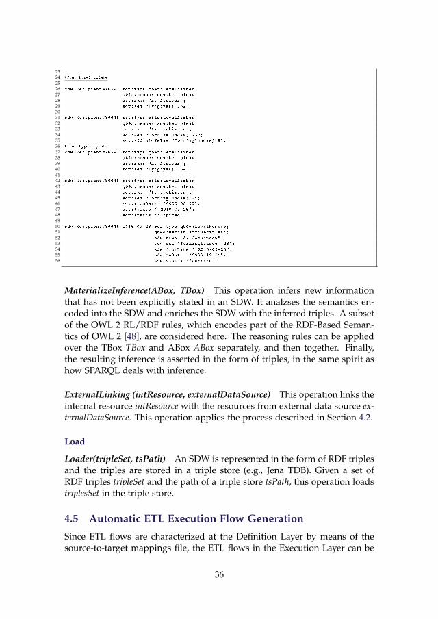
2324 After type3 update
2526 sdw:Recipient #76291 rdf:type qb4o:LevelMember;
27 qb4o:member sdw:Recipient;
28 sdw:name "R. Nielsen";
29 sdw:add "Lyngbyvej 369".
3031 sdw:Recipient #86646 rdf:type qb4o:LevelMember;
32 qb4o:member sdw:Recipient;
33 sdw:name "A. Jochimsen";
34 sdw:add "Torninglundvej 23";
35 sdw:add_oldValue "Torninglundvej 9".
36 After type2 update
37 sdw:Recipient #76291 rdf:type qb4o:LevelMember;
38 qb4o:member sdw:Recipient;
39 sdw:name "R. Nielsen";
40 sdw:add "Lyngbyvej 369".
4142 sdw:Recipient #86646 rdf:type qb4o:LevelMember;
43 qb4o:member sdw:Recipient;
44 sdw:name "A. Jochimsen";
45 sdw:add "Torninglundvej 9";
46 sdw:fromDate ``0000-00-00";
47 sdw:toDate ``2016-09-25";
48 sdw:status ``Expired".
4950 sdw:Recipient #86646 _2016_09_26 rdf:type qb4o:LevelMember;
51 qb4o:member sdw:Recipient;
52 sdw:name "A. Jochimsen";
53 sdw:add "Torninglundvej 23";
54 sdw:fromDate ``2016-09-26";
55 sdw:toDate ``9999-12-31";
56 sdw:status ``Current".
MaterializeInference(ABox, TBox) This operation infers new informationthat has not been explicitly stated in an SDW. It analzses the semantics en-coded into the SDW and enriches the SDW with the inferred triples. A subsetof the OWL 2 RL/RDF rules, which encodes part of the RDF-Based Seman-tics of OWL 2 [48], are considered here. The reasoning rules can be appliedover the TBox TBox and ABox ABox separately, and then together. Finally,the resulting inference is asserted in the form of triples, in the same spirit ashow SPARQL deals with inference.
ExternalLinking (intResource, externalDataSource) This operation links theinternal resource intResource with the resources from external data source ex-ternalDataSource. This operation applies the process described in Section 4.2.
Load
Loader(tripleSet, tsPath) An SDW is represented in the form of RDF triplesand the triples are stored in a triple store (e.g., Jena TDB). Given a set ofRDF triples tripleSet and the path of a triple store tsPath, this operation loadstriplesSet in the triple store.
4.5 Automatic ETL Execution Flow Generation
Since ETL flows are characterized at the Definition Layer by means of thesource-to-target mappings file, the ETL flows in the Execution Layer can be
36
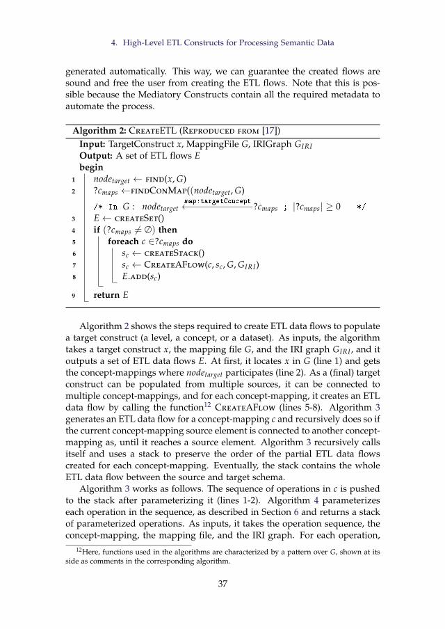
4. High-Level ETL Constructs for Processing Semantic Data
generated automatically. This way, we can guarantee the created flows aresound and free the user from creating the ETL flows. Note that this is pos-sible because the Mediatory Constructs contain all the required metadata toautomate the process.
Algorithm 2: CreateETL (Reproduced from [17])Input: TargetConstruct x, MappingFile G, IRIGraph GIRIOutput: A set of ETL flows Ebegin
1 nodetarget ← find(x, G)2 ?cmaps ←findConMap((nodetarget, G)
/* In G : nodetargetmap:targetConcept←−−−−−−−−−−−?cmaps ; |?cmaps| ≥ 0 */
3 E← createSet()4 if (?cmaps 6= ∅) then5 foreach c ∈?cmaps do6 sc ← createStack()7 sc ← CreateAFlow(c, sc, G, GIRI)8 E.add(sc)
9 return E
Algorithm 2 shows the steps required to create ETL data flows to populatea target construct (a level, a concept, or a dataset). As inputs, the algorithmtakes a target construct x, the mapping file G, and the IRI graph GIRI , and itoutputs a set of ETL data flows E. At first, it locates x in G (line 1) and getsthe concept-mappings where nodetarget participates (line 2). As a (final) targetconstruct can be populated from multiple sources, it can be connected tomultiple concept-mappings, and for each concept-mapping, it creates an ETLdata flow by calling the function12 CreateAFlow (lines 5-8). Algorithm 3generates an ETL data flow for a concept-mapping c and recursively does so ifthe current concept-mapping source element is connected to another concept-mapping as, until it reaches a source element. Algorithm 3 recursively callsitself and uses a stack to preserve the order of the partial ETL data flowscreated for each concept-mapping. Eventually, the stack contains the wholeETL data flow between the source and target schema.
Algorithm 3 works as follows. The sequence of operations in c is pushedto the stack after parameterizing it (lines 1-2). Algorithm 4 parameterizeseach operation in the sequence, as described in Section 6 and returns a stackof parameterized operations. As inputs, it takes the operation sequence, theconcept-mapping, the mapping file, and the IRI graph. For each operation,
12Here, functions used in the algorithms are characterized by a pattern over G, shown at itsside as comments in the corresponding algorithm.
37
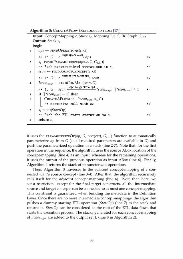
Algorithm 3: CreateAFlow (Reproduced from [17])Input: ConceptMapping c, Stack sc, MappingFile G, IRIGraph GIRIOutput: Stack scbegin
1 ops← findOperations(c, G)
/* In G : cmap:operation−−−−−−−−−→ ops */
2 sc. push(Parameterize(ops, c, G, GIRI))/* Push parameterized operations in sc */
3 scon← findSourceConcept(c, G)
/* In G : cmap:sourceConcept−−−−−−−−−−−→ scon */
4 ?sconmap ← findConMap(scon, G)
/* In G : sconmap:targetConcept←−−−−−−−−−−−?sconmap; |?sconmap| ≤ 1 */
5 if (|?sconmap| = 1) then6 CreateAFlow(nc ∈?sconmap, sc, G)
/* recursive call with nc */
7 sc.push(StartOp)/* Push the ETL start operation to sc */
8 return sc
it uses the parameterizeOp(op, G, loc(cm), GIRI) function to automaticallyparameterize op from G (as all required parameters are available in G) andpush the parameterized operation in a stack (line 2-7). Note that, for the firstoperation in the sequence, the algorithm uses the source ABox location of theconcept-mapping (line 4) as an input, whereas for the remaining operations,it uses the output of the previous operation as input ABox (line 6). Finally,Algorithm 4 returns the stack of parameterized operations.
Then, Algorithm 3 traverses to the adjacent concept-mapping of c con-nected via c’s source concept (line 3-4). After that, the algorithm recursivelycalls itself for the adjacent concept-mapping (line 6). Note that, here, weset a restriction: except for the final target constructs, all the intermediatesource and target concepts can be connected to at most one concept-mapping.This constraint is guaranteed when building the metadata in the DefinitionLayer. Once there are no more intermediate concept-mappings, the algorithmpushes a dummy starting ETL operation (StartOp) (line 7) to the stack andreturns it. StartOp can be considered as the root of the ETL data flows thatstarts the execution process. The stacks generated for each concept-mappingof nodetarget are added to the output set E (line 8 in Algorithm 2).
38
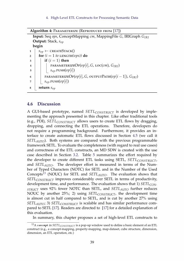
4. High-Level ETL Constructs for Processing Semantic Data
Algorithm 4: Parameterize (Reproduced from [17])Input: Seq ops, ConceptMapping cm, MappingFile G, IRIGraph GIRIOutput: Stack, sopbegin
1 sop ← createStack()2 for (i = 1 to length(ops)) do3 if (i = 1) then4 parameterizeOp(op[i], G, loc(cm), GIRI)5 sop.push(op[i])
6 parameterizeOp(op[i], G, outputPath(op[i− 1]), GIRI)7 sop.push(op[i])
8 return sop
4.6 Discussion
A GUI-based prototype, named SETLCONSTRUCT is developed by imple-menting the approach presented in this chapter. Like other traditional tools(e.g., PDI), SETLCONSTRUCT allows users to create ETL flows by dragging,dropping, and connecting the ETL operations. Therefore, developers donot require a programming background. Furthermore, it provides an in-terface to create automatic ETL flows discussed in Section 4.5 (we call itSETLAUTO). Both systems are compared with the previous programmableframework SETL. To evaluate the completeness (with regard to real use cases)and correctness of the ETL constructs, an MD SDW is created with the usecase described in Section 3.2. Table 5 summarizes the effort required bythe developer to create different ETL tasks using SETL, SETLCONSTRUCT ,and SETLAUTO. The developer effort is measured in terms of the Num-ber of Typed Characters (NOTC) for SETL and in the Number of the UsedConcepts13 (NOUC) for SETL and SETLAUTO. The evaluation shows thatSETLCONSTRUCT improves considerably over SETL in terms of productivity,development time, and performance. The evaluation shows that 1) SETLCON-
STRUCT uses 92% fewer NOTC than SETL, and SETLAUTO further reducesNOUC by another 25%; 2) using SETLCONSTRUCT, the development timeis almost cut in half compared to SETL, and is cut by another 27% usingSETLAUTO; 3) SETLCONSTRUCT is scalable and has similar performance com-pared to SETL [17]. Readers are directed to [17] for a detailed explanation ofthis evaluation.
In summary, this chapter proposes a set of high-level ETL constructs to
13A concept in SETLCONSTRUCT is a pop-up window used to define a basic element of an ETLconstruct (e.g., a concept-mapping, property-mapping, map-dataset, cube structure, dimension,dimension, an ETL operation, etc.)
39
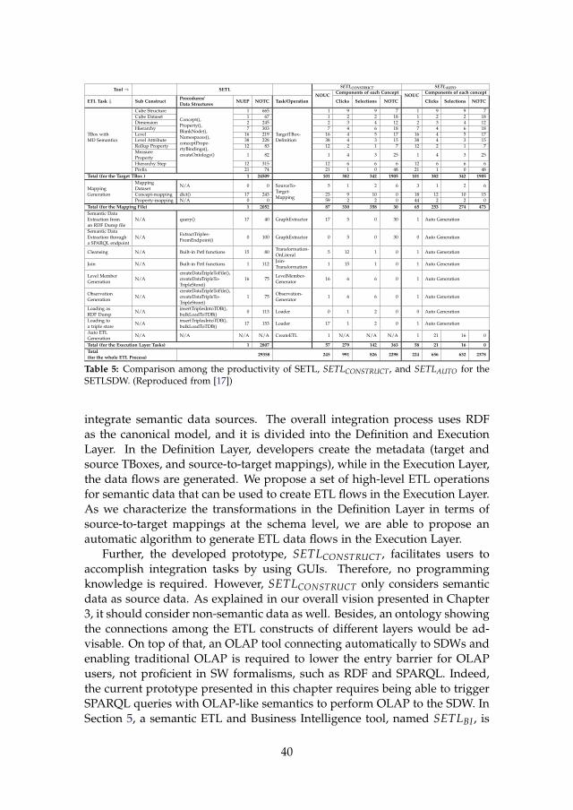
Tool⇒ SETLSETLCONSTRUCT SETLAUTO
NOUCComponents of each Concept
NOUCComponents of each concept
ETL Task ⇓ Sub ConstructProcedures/Data Structures
NUEP NOTC Task/Operation Clicks Selections NOTC Clicks Selections NOTC
TBox withMD Semantics
Cube Structure
Concept(),Property(),BlankNode(),Namespaces(),conceptPrope-rtyBindings(),createOntology()
1 665
TargetTBox-Definition
1 9 9 7 1 9 9 7Cube Dataset 1 67 1 2 2 18 1 2 2 18Dimension 2 245 2 3 4 12 2 3 4 12Hierarchy 7 303 7 4 6 18 7 4 6 18Level 16 219 16 4 5 17 16 4 5 17Level Attribute 38 228 38 4 3 15 38 4 3 15Rollup Property 12 83 12 2 1 7 12 2 1 7MeasureProperty
1 82 1 4 3 25 1 4 3 25
Hierarchy Step 12 315 12 6 6 6 12 6 6 6Prefix 21 74 21 1 0 48 21 1 0 48
Total (for the Target TBox ) 1 24509 101 382 342 1905 101 382 342 1905
MappingGeneration
MappingDataset
N/A 0 0 SourceTo-Target-Mapping
5 1 2 6 3 1 2 6
Concept-mapping dict() 17 243 23 9 10 0 18 12 10 15Property-mapping N/A 0 0 59 2 2 0 44 2 2 0
Total (for the Mapping File) 1 2052 87 330 358 30 65 253 274 473Semantic DataExtraction froman RDF Dump file
N/A query() 17 40 GraphExtractor 17 5 0 30 1 Auto Generation
Semantic DataExtraction througha SPARQL endpoint
N/AExtractTriples-FromEndpoint()
0 100 GraphExtractor 0 5 0 30 0 Auto Generation
Cleansing N/A Built-in Petl functions 15 80Transformation-OnLiteral
5 12 1 0 1 Auto Generation
Join N/A Built-in Petl functions 1 112Join-Transformation
1 15 1 0 1 Auto Generation
Level MemberGeneration
N/AcreateDataTripleToFile(),createDataTripleTo-TripleStore()
16 75LevelMember-Generator
16 6 6 0 1 Auto Generation
ObservationGeneration
N/AcreateDataTripleToFile(),createDataTripleTo-TripleStore()
1 75Observation-Generator
1 6 6 0 1 Auto Generation
Loading asRDF Dump
N/AinsertTriplesIntoTDB(),bulkLoadToTDB()
0 113 Loader 0 1 2 0 0 Auto Generation
Loading toa triple store
N/AinsertTriplesIntoTDB(),bulkLoadToTDB()
17 153 Loader 17 1 2 0 1 Auto Generation
Auto ETLGeneration
N/A N/A N/A N/A CreateETL 1 N/A N/A N/A 1 21 16 0
Total (for the Execution Layer Tasks) 1 2807 57 279 142 363 58 21 16 0Total(for the whole ETL Process)
29358 245 991 826 2298 224 656 632 2378
Table 5: Comparison among the productivity of SETL, SETLCONSTRUCT, and SETLAUTO for theSETLSDW. (Reproduced from [17])
integrate semantic data sources. The overall integration process uses RDFas the canonical model, and it is divided into the Definition and ExecutionLayer. In the Definition Layer, developers create the metadata (target andsource TBoxes, and source-to-target mappings), while in the Execution Layer,the data flows are generated. We propose a set of high-level ETL operationsfor semantic data that can be used to create ETL flows in the Execution Layer.As we characterize the transformations in the Definition Layer in terms ofsource-to-target mappings at the schema level, we are able to propose anautomatic algorithm to generate ETL data flows in the Execution Layer.
Further, the developed prototype, SETLCONSTRUCT , facilitates users toaccomplish integration tasks by using GUIs. Therefore, no programmingknowledge is required. However, SETLCONSTRUCT only considers semanticdata as source data. As explained in our overall vision presented in Chapter3, it should consider non-semantic data as well. Besides, an ontology showingthe connections among the ETL constructs of different layers would be ad-visable. On top of that, an OLAP tool connecting automatically to SDWs andenabling traditional OLAP is required to lower the entry barrier for OLAPusers, not proficient in SW formalisms, such as RDF and SPARQL. Indeed,the current prototype presented in this chapter requires being able to triggerSPARQL queries with OLAP-like semantics to perform OLAP to the SDW. InSection 5, a semantic ETL and Business Intelligence tool, named SETLBI , is
40
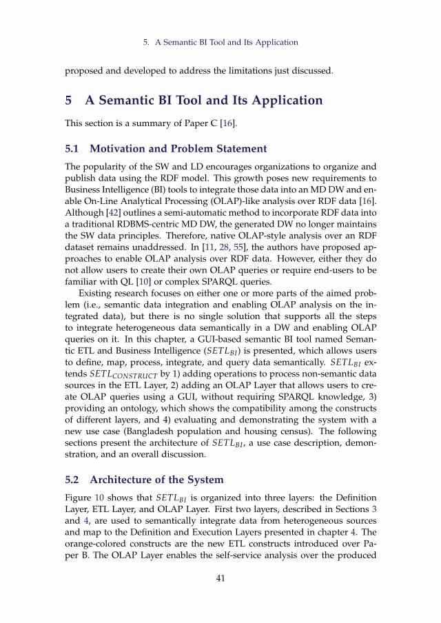
5. A Semantic BI Tool and Its Application
proposed and developed to address the limitations just discussed.
5 A Semantic BI Tool and Its Application
This section is a summary of Paper C [16].
5.1 Motivation and Problem Statement
The popularity of the SW and LD encourages organizations to organize andpublish data using the RDF model. This growth poses new requirements toBusiness Intelligence (BI) tools to integrate those data into an MD DW and en-able On-Line Analytical Processing (OLAP)-like analysis over RDF data [16].Although [42] outlines a semi-automatic method to incorporate RDF data intoa traditional RDBMS-centric MD DW, the generated DW no longer maintainsthe SW data principles. Therefore, native OLAP-style analysis over an RDFdataset remains unaddressed. In [11, 28, 55], the authors have proposed ap-proaches to enable OLAP analysis over RDF data. However, either they donot allow users to create their own OLAP queries or require end-users to befamiliar with QL [10] or complex SPARQL queries.
Existing research focuses on either one or more parts of the aimed prob-lem (i.e., semantic data integration and enabling OLAP analysis on the in-tegrated data), but there is no single solution that supports all the stepsto integrate heterogeneous data semantically in a DW and enabling OLAPqueries on it. In this chapter, a GUI-based semantic BI tool named Seman-tic ETL and Business Intelligence (SETLBI) is presented, which allows usersto define, map, process, integrate, and query data semantically. SETLBI ex-tends SETLCONSTRUCT by 1) adding operations to process non-semantic datasources in the ETL Layer, 2) adding an OLAP Layer that allows users to cre-ate OLAP queries using a GUI, without requiring SPARQL knowledge, 3)providing an ontology, which shows the compatibility among the constructsof different layers, and 4) evaluating and demonstrating the system with anew use case (Bangladesh population and housing census). The followingsections present the architecture of SETLBI , a use case description, demon-stration, and an overall discussion.
5.2 Architecture of the System
Figure 10 shows that SETLBI is organized into three layers: the DefinitionLayer, ETL Layer, and OLAP Layer. First two layers, described in Sections 3and 4, are used to semantically integrate data from heterogeneous sourcesand map to the Definition and Execution Layers presented in chapter 4. Theorange-colored constructs are the new ETL constructs introduced over Pa-per B. The OLAP Layer enables the self-service analysis over the produced
41
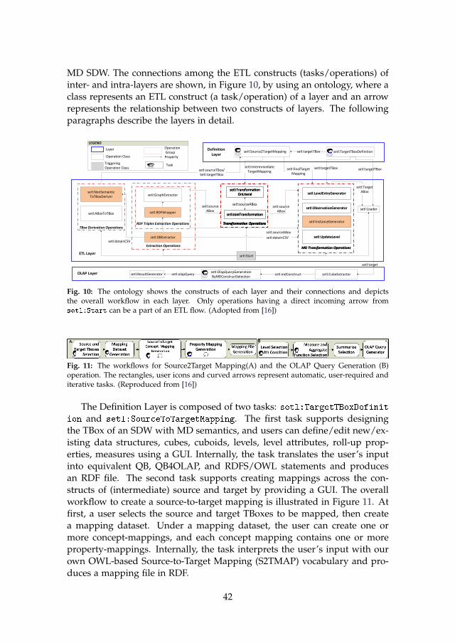
MD SDW. The connections among the ETL constructs (tasks/operations) ofinter- and intra-layers are shown, in Figure 10, by using an ontology, where aclass represents an ETL construct (a task/operation) of a layer and an arrowrepresents the relationship between two constructs of layers. The followingparagraphs describe the layers in detail.
setl:Loader
setl:Start
setl:TargetTBoxDefinition setl:Source2TargetMapping setl:targetTBox
ETL Layer
Definition Layer
setl:targetTBoxsetl:sourceTBox/Setl:targetTBox
OLAP Layer setl:CubeExtractorsetl:OlapQueryGenerationByMDConstructSelection
setl:ResultGenerator setl:mdConstruct
setl:target
setl:TargetABox
setl:olapQuery
setl:targetTBox
setl:NonSemanticToTBoxDeriver
setl:ABoxToTBox
TBox Derivation Operations
setl:LevelEntryGenerator
setl:ObservationGenerator
setl:InstanceGenerator
setl:UpdateLevel
MD Transformation Operations
setl:LevelEntryGenerator
setl:ObservationGenerator
setl:InstanceGenerator
setl:UpdateLevel
MD Transformation Operations
LEGEND
Operation Class
Layer
Triggering Operation Class
Property
Task
setl:TransformationOnLiteral
setl:JoinTransformation
Transformation Operations
setl:TransformationOnLiteral
setl:JoinTransformation
Transformation Operations
setl:sourceABox
setl:TransformationOnLiteral
setl:JoinTransformation
Transformation Operations
setl:sourceABox
setl:RDFWrapper
setl:GraphExtractor
Extraction Operations
setl:DBExtractor
RDF Triples Extraction Operations
setl:sourceABox
setl:sourceABox
setl:datainCSV
setl:finalTargetMapping
setl:IntermmediateTargetMapping
setl:sourceABox
Operation Group
setl:datainCSV
Fig. 10: The ontology shows the constructs of each layer and their connections and depictsthe overall workflow in each layer. Only operations having a direct incoming arrow fromsetl:Start can be a part of an ETL flow. (Adopted from [16])
Fig. 11: The workflows for Source2Target Mapping(A) and the OLAP Query Generation (B)operation. The rectangles, user icons and curved arrows represent automatic, user-required anditerative tasks. (Reproduced from [16])
The Definition Layer is composed of two tasks: setl:TargetTBoxDefinition and setl:SourceToTargetMapping. The first task supports designingthe TBox of an SDW with MD semantics, and users can define/edit new/ex-isting data structures, cubes, cuboids, levels, level attributes, roll-up prop-erties, measures using a GUI. Internally, the task translates the user’s inputinto equivalent QB, QB4OLAP, and RDFS/OWL statements and producesan RDF file. The second task supports creating mappings across the con-structs of (intermediate) source and target by providing a GUI. The overallworkflow to create a source-to-target mapping is illustrated in Figure 11. Atfirst, a user selects the source and target TBoxes to be mapped, then createa mapping dataset. Under a mapping dataset, the user can create one ormore concept-mappings, and each concept mapping contains one or moreproperty-mappings. Internally, the task interprets the user’s input with ourown OWL-based Source-to-Target Mapping (S2TMAP) vocabulary and pro-duces a mapping file in RDF.
42
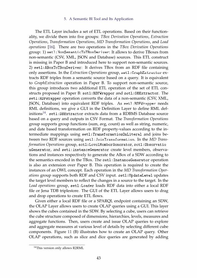
5. A Semantic BI Tool and Its Application
The ETL Layer includes a set of ETL operations. Based on their function-ality, we divide them into five groups: TBox Derivation Operations, ExtractionOperations, Transformation Operations, MD Transformation Operations, and Loadoperations [16]. There are two operations in the TBox Derivation Operationsgroup: 1) setl:NonSemanticToTBoxDeriver: It allows to derive TBoxes fromnon-semantic (CSV, XML, JSON and Database) sources. This ETL constructis missing in Paper B and introduced here to support non-semantic sources.2) setl:ABoxToTBoxDeriver: It derives TBox from an RDF file containingonly assertions. In the Extraction Operations group, setl:GraphExtractor ex-tracts RDF triples from a semantic source based on a query. It is equivalentto GraphExtraction operation in Paper B. To support non-semantic source,this group introduces two additional ETL operation of the set of ETL con-structs proposed in Paper B: setl:RDFWrapper and setl:DBExtractor. Thesetl:RDFWrapper operation converts the data of a non-semantic (CSV, XML,JSON, Database) into equivalent RDF triples. As setl:RDFWrapper needsRML definitions, we give a GUI in the Definition Layer to define RML def-initions14. setl:DBExtractor extracts data from a RDBMS Database sourcebased on a query and outputs in CSV Format. The Transformation Operationsgroup supports group functions (sum, avg, count) as well as string, numeric,and date based transformation on RDF property-values according to the in-termediate mappings using setl:TransformationOnLiteral and joins be-tween two RDF sources using setl:JoinTransformation. In the MD Trans-formation Operations group, setl:LevelMemberGenerator, setl:Observatio-nGenerator, and setl:InstanceGenerator create level members, observa-tions and instances respectively to generate the ABox of a SDW according tothe semantics encoded in the TBox. The setl:InstanceGenerator operationis also an extension over Paper B. This operation is required to create theinstances of an OWL concept. Each operation in the MD Transformation Oper-ations group supports both RDF and CSV input. setl:UpdateLevel updatesthe target level members to reflect the changes in a source to the target. In theLoad operations group, setl:Loader loads RDF data into either a local RDFfile or Jena TDB triplestore. The GUI of the ETL Layer allows users to dragand drop operations to create ETL flows.
Given either a local RDF file or a SPARQL endpoint containing an SDW,the OLAP Layer allows users to create OLAP queries using a GUI. This layershows the cubes contained in the SDW. By selecting a cube, users can retrievethe cube structure composed of dimensions, hierarchies, levels, measures andaggregate functions. Then, users create and issue OLAP queries to exploreand aggregate measures at various level of details by selecting different cubecomponents. Figure 11 (B) illustrates how to create an OLAP query. OtherOLAP operations, such as slice and dice queries are generated by adding
14This version only allows R2RML
43
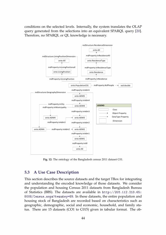
conditions on the selected levels. Internally, the system translates the OLAPquery generated from the selections into an equivalent SPARQL query [20].Therefore, no SPARQL or QL knowledge is necessary.
onto:Residence
onto:ADM5
onto:PopulationC01
onto:All
onto:ResidenceType
onto:ADM4
onto:ADM3
onto:LivingPosition
mdProperty:inAdm5
mdProperty:inResidenceAll
mdProperty:inResidenceType
mdProperty:inResidence
xsd:doublemdProperty:#ofPeople
mdStructure:ResidenceDimension
mdStructure:GeographyDimension
LEGEND
Class
Object Property
DataType Property
LEGEND
Class
Object Property
DataType Property
Dimension
LEGEND
Class
Object Property
DataType Property
Dimension
onto:ADM2
onto:All
onto:ADM1
onto:ADM4
onto:ADM4
mdProperty:inCity
mdProperty:inMunicipality
mdProperty:inAdm3
mdProperty:inAdm2
onto:All
mdProperty:inLivingPosition
mdStructure:LivingPositionDimension
mdProperty:inLivingPositionall
mdProperty:inAdm3
mdProperty:inAdm2
mdProperty:inAdm1
mdProperty:inAll
mdProperty:inAdm4
Fig. 12: The ontology of the Bangladesh census 2011 dataset C01.
5.3 A Use Case Description
This section describes the source datasets and the target TBox for integratingand understanding the encoded knowledge of those datasets. We considerthe population and housing Census 2011 datasets from Bangladesh Bureauof Statistics (BBS). The datasets are available in http://203.112.218.65:
8008/Census.aspx?MenuKey=89. In these datasets, the entire population andhousing stock of Bangladesh are recorded based on characteristics such asgeographic, demographic, social and economic, household, and family sta-tus. There are 15 datasets (CO1 to C015) given in tabular format. The ob-
44
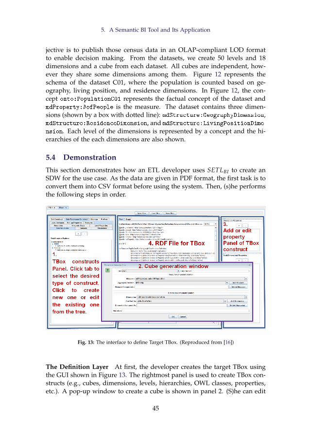
5. A Semantic BI Tool and Its Application
jective is to publish those census data in an OLAP-compliant LOD formatto enable decision making. From the datasets, we create 50 levels and 18dimensions and a cube from each dataset. All cubes are independent, how-ever they share some dimensions among them. Figure 12 represents theschema of the dataset C01, where the population is counted based on ge-ography, living position, and residence dimensions. In Figure 12, the con-cept onto:PopulationC01 represents the factual concept of the dataset andmdProperty:#ofPeople is the measure. The dataset contains three dimen-sions (shown by a box with dotted line): mdStructure:GeographyDimension,mdStructure:ResidenceDimension, and mdStructure:LivingPositionDime-
nsion. Each level of the dimensions is represented by a concept and the hi-erarchies of the each dimensions are also shown.
5.4 Demonstration
This section demonstrates how an ETL developer uses SETLBI to create anSDW for the use case. As the data are given in PDF format, the first task is toconvert them into CSV format before using the system. Then, (s)he performsthe following steps in order.
Fig. 13: The interface to define Target TBox. (Reproduced from [16])
The Definition Layer At first, the developer creates the target TBox usingthe GUI shown in Figure 13. The rightmost panel is used to create TBox con-structs (e.g., cubes, dimensions, levels, hierarchies, OWL classes, properties,etc.). A pop-up window to create a cube is shown in panel 2. (S)he can edit
45
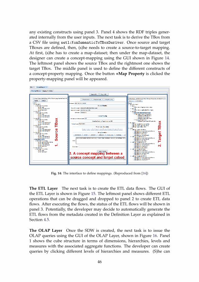
any existing constructs using panel 3. Panel 4 shows the RDF triples gener-ated internally from the user inputs. The next task is to derive the TBox froma CSV file using setl:NonSemanticToTBoxDeriver. Once source and targetTBoxes are defined, then, (s)he needs to create a source-to-target mapping.At first, (s)he has to create a map-dataset; then under the map-dataset, thedesigner can create a concept-mapping using the GUI shown in Figure 14.The leftmost panel shows the source TBox and the rightmost one shows thetarget TBox. The middle panel is used to define the different constructs ofa concept-property mapping. Once the button +Map Property is clicked theproperty-mapping panel will be appeared.
Fig. 14: The interface to define mappings. (Reproduced from [16])
The ETL Layer The next task is to create the ETL data flows. The GUI ofthe ETL Layer is shown in Figure 15. The leftmost panel shows different ETLoperations that can be dragged and dropped to panel 2 to create ETL dataflows. After executing the flows, the status of the ETL flows will be shown inpanel 3. Potentially, the developer may decide to automatically generate theETL flows from the metadata created in the Definition Layer as explained inSection 4.5.
The OLAP Layer Once the SDW is created, the next task is to issue theOLAP queries using the GUI of the OLAP Layer, shown in Figure 16. Panel1 shows the cube structure in terms of dimensions, hierarchies, levels andmeasures with the associated aggregate functions. The developer can createqueries by clicking different levels of hierarchies and measures. (S)he can
46
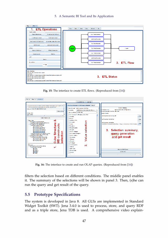
5. A Semantic BI Tool and Its Application
Fig. 15: The interface to create ETL flows. (Reproduced from [16])
Fig. 16: The interface to create and run OLAP queries. (Reproduced from [16])
filters the selection based on different conditions. The middle panel enablesit. The summary of the selections will be shown in panel 3. Then, (s)he canrun the query and get result of the query.
5.5 Prototype Specifications
The system is developed in Java 8. All GUIs are implemented in StandardWidget Toolkit (SWT). Jena 3.4.0 is used to process, store, and query RDFand as a triple store, Jena TDB is used. A comprehensive video explain-
47
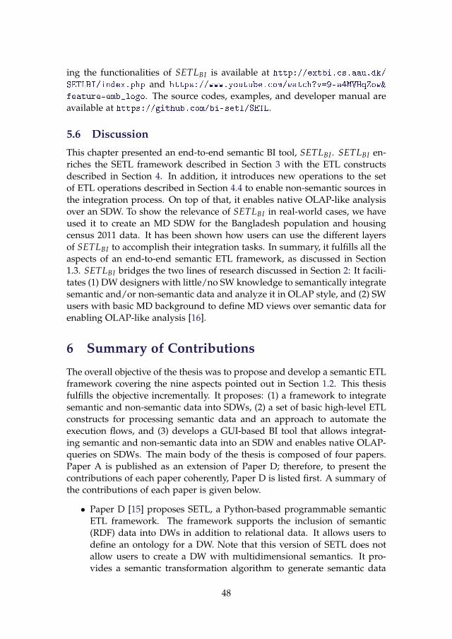
ing the functionalities of SETLBI is available at http://extbi.cs.aau.dk/
SETLBI/index.php and https://www.youtube.com/watch?v=9-a4MVHqZow&
feature=emb_logo. The source codes, examples, and developer manual areavailable at https://github.com/bi-setl/SETL.
5.6 Discussion
This chapter presented an end-to-end semantic BI tool, SETLBI . SETLBI en-riches the SETL framework described in Section 3 with the ETL constructsdescribed in Section 4. In addition, it introduces new operations to the setof ETL operations described in Section 4.4 to enable non-semantic sources inthe integration process. On top of that, it enables native OLAP-like analysisover an SDW. To show the relevance of SETLBI in real-world cases, we haveused it to create an MD SDW for the Bangladesh population and housingcensus 2011 data. It has been shown how users can use the different layersof SETLBI to accomplish their integration tasks. In summary, it fulfills all theaspects of an end-to-end semantic ETL framework, as discussed in Section1.3. SETLBI bridges the two lines of research discussed in Section 2: It facili-tates (1) DW designers with little/no SW knowledge to semantically integratesemantic and/or non-semantic data and analyze it in OLAP style, and (2) SWusers with basic MD background to define MD views over semantic data forenabling OLAP-like analysis [16].
6 Summary of Contributions
The overall objective of the thesis was to propose and develop a semantic ETLframework covering the nine aspects pointed out in Section 1.2. This thesisfulfills the objective incrementally. It proposes: (1) a framework to integratesemantic and non-semantic data into SDWs, (2) a set of basic high-level ETLconstructs for processing semantic data and an approach to automate theexecution flows, and (3) develops a GUI-based BI tool that allows integrat-ing semantic and non-semantic data into an SDW and enables native OLAP-queries on SDWs. The main body of the thesis is composed of four papers.Paper A is published as an extension of Paper D; therefore, to present thecontributions of each paper coherently, Paper D is listed first. A summary ofthe contributions of each paper is given below.
• Paper D [15] proposes SETL, a Python-based programmable semanticETL framework. The framework supports the inclusion of semantic(RDF) data into DWs in addition to relational data. It allows users todefine an ontology for a DW. Note that this version of SETL does notallow users to create a DW with multidimensional semantics. It pro-vides a semantic transformation algorithm to generate semantic data
48
6. Summary of Contributions
from the source data according to the semantics encoded in the on-tology. It also provides a method to connect internal DW data withexternal knowledge bases. Hence, it creates a knowledge base com-posed of an ontology and its instances where data are semanticallyconnected with other external/internal data. A comprehensive experi-mental evaluation comparing SETL to a solution using traditional toolson the use case of Danish Agricultural and Business datasets showsthat SETL provides better performance, programmer productivity, andknowledge base quality [15].
• Paper A [39] significantly extends Paper D [15]. Here, we redefinethe architecture of SETL by 1) dividing it into three layers: the Defi-nition Layer, ETL Layer, and Data Warehouse Layer, 2) adding a sub-component QB4OLAP for defining a target TBox (schema) with mul-tidimensional (MD) semantics, 3) adding a semantic layer on top ofnon-semantic sources, and 4) adding a provenance graph to captureprovenance information of IRIs. The design and implementation of theframework are presented separately. The design section includes theformal description of the components of the architecture. The versionof the semantic transformation algorithm in Paper D is updated to re-flect the MD semantics encoded in the target TBox at the data level. Thedeveloped Python-based programmable framework helps developersby providing a higher-level abstraction that lowers the entry barriers.Thus, one of the contributions is to automatically map the high-levelabstraction to executable code [39]. For evaluating SETL, an SDW iscreated with MD semantics by integrating the Danish Business datasetand an EU subsidy dataset using SETL and compare the process withother tools/solutions. The evaluation shows that SETL represents aconsiderable improvement over the competing solutions/tools in termsof programmer productivity, knowledge base quality, and performance.SETL sets the foundations for the rest of the papers.
• Paper B [17] outlines an integration process, focusing on the usageof RDF as the canonical model, to integrate data from semantic datasources into an SDW. The overall integration process is divided intotwo layers: the Definition Layer and the Execution Layer. This paperproposes a set of high-level ETL constructs (tasks/operations) for eachlayer to process semantic data. The Definition Layer includes two tasksand one ABox-to-TBox derivation operation. The two tasks allow ETLdesigners to define target schemas and mappings between semanticdata sources and the target schemas, whereas the ABox-to-TBox opera-tion derives a TBox from a given ABox. A mapping vocabulary calledS2TMAP is proposed here to enable semantic annotations of the map-pings. In the Execution Layer, a set of high-level ETL operations are
49
proposed to process semantic data sources. In addition to the cleansing,join, group, and data type based transformations for semantic data, op-erations are proposed to create multidimensional semantics at the datalevel and to update the SDW to reflect the changes of source data. Here,we show how different types of updates [35] used in traditional DW canbe applied to an SDW. Different from SETL and other ETL tools, thislayer proposes a new paradigm: the ETL flow transformations are char-acterized at the Definition Layer instead of independently within eachETL operation (in the Execution Layer). Thus, we are able to proposean algorithm to automatically generate ETL data flows in the Execu-tion Layer. Finally, a GUI-based prototype, named SETLCONSTRUCT isdeveloped by implementing all the ETL constructs proposed here. Weprovide an extensive evaluation to compare the productivity, quality,and performance of the proposed ETL operations with the previousframework SETL [39]. The evaluation shows that SETLCONSTRUCT im-proves considerably over SETL in terms of productivity, developmenttime, and performance. The evaluation shows that 1) SETLCONSTRUCTuses 92% fewer NOTC than SETL, and SETLAUTO (the extension ofSETLCONSTRUCT that enables automatic ETL execution flow generation)further reduces NOUC by another 25%; 2) using SETLCONSTRUCT, thedevelopment time is almost cut in half compared to SETL, and is cutby another 27% using SETLAUTO; 3) SETLCONSTRUCT is scalable and hassimilar performance compared to SETL [17].
• Paper C [16] presents the SETLBI (Semantic Extract-Transform-Loadand Business Intelligence) integration platform that (1) covers all phasesof integration: target definition, source-to-target mappings, semanticand non-semantic source extraction, data transformation, target popu-lation, and update and (2) enables OLAP-like analyses over an SDW.SETLBI is organized into three layers: the Definition Layer, ETL Layer,and OLAP Layer. Each layer is composed of a set of tasks/operations.The intra- and inter-layer connections among the constructs of layersare presented using an ontology. In addition to the ETL operationsproposed in the Execution Layer of Paper B, the ETL Layer includesoperations to process non-semantic data sources. The OLAP Layer pro-vides a GUI to enable self-service OLAP analysis over an SDW. We usethe Bangladesh 2011 population census data as a use case to demon-strate SETLBI . Using SETLBI , we generate an SDW with census datathat can be analyzed using OLAP queries.
The problem that motivated the thesis was twofold: 1) the integration ofsemantic and non-semantic data into an MD DW semantically, and 2) en-abling OLAP analysis over SW data. The solutions to this problem will fusethe benefits of BI and SW technologies; thus, both BI and SW communi-
50
7. Future Work Directions
ties will benefit. We set a hypothesis for the thesis “In the context of highlyheterogeneous data integration processes, considering semantics as first-class citizenfacilitates the integration process by providing automation and lower entry barri-ers for non-technical users." In this direction, as an output, Paper A providesa Python-based programmable framework SETL that provides a number ofpowerful modules, classes, and methods. SETL allows ETL developers tointegrate semantic and non-semantic data programmatically. Paper B pro-vides a GUI-based prototype SETLCONSTRUCT , which allows non-technicalusers to integrate semantic data in an SDW where the RDF model is usedas the canonical model to make semantics as first-class citizen. Importantly,SETLCONSTRUCT allows automatic ETL data flows generation. Paper C pro-vides the final contribution of this thesis: the BI tool SETLBI . SETLBI facili-tates (1) DW designers with little/no SW knowledge to semantically integratesemantic and/or non-semantic data and analyze it in OLAP style, and (2) SWusers with basic MD background to define MD views over semantic data forenabling OLAP-like analysis [16]. Additionally, SW users can enrich the gen-erated SDW’s schema with RDFS/OWL constructs. Using the developed toolwe generated an MD SDW using real-world data. Therefore, we empiricallyprove the hypothesis of this thesis by creating a system that fulfills all identi-fied aspects of semantic ETL.
7 Future Work Directions
Due to the popularity and high acceptance rate of SW and LD, nowadays,technologies are shifting from a database centric concept to a knowledge basecentric concept, where semantic data play an important role. This projectwill be a guideline for accelerating this shifting process. Taking the proposedframework SETL as a foundation, researchers can aim to develop further in-teractive and automatic integration frameworks for the Big Data and DataLake environments. This project bridges the traditional BI technologies andSW technologies, which in turn will open the door for further research op-portunities like developing machine-understandable ETL and warehousingtechniques. In the following, we give specific pointers to future work.
SETL uses a demand-driven approach to design an (MD) SDW, i.e., basedon user requirements, a DW designer designs the TBox of an SDW. Theframework can be extended to follow a source-driven approach where dif-ferent source schemas are aligned and merged to produce a single source oftruth (the target TBox). Different ontology matching and merging techniquescan be utilized to (semi)automatically create the target TBox.
SETLCONSTRUCT allows users to create source-to-target mappings manu-ally. However, an algorithm can be developed to create the mappings (semi-)automatically. Another extension of this work is to define the formal se-
51
References
mantics of the operations using an ontology and mathematically prove thecorrectness and completeness of the proposed ETL constructs.
To enable the utmost benefit of Exploratory OLAP, the system shouldexplore SW search engines, data hubs, and knowledge bases and dynamicallysuggest relevant data sources to enrich MD constructs and evolve the targetschema.
We use the Jena TDB triplestore to load an SDW. Other triple storesand/or graph databases can be explored to get better loading and queryperformance. Also, exploring the physical optimization of named graphs canbe an interesting extension.
The source-to-target mappings act as a mediator to generate data accord-ing to the semantics encoded in the target. Therefore, the next extension ofthis work is to extend the framework from purely physical to also virtualdata integration where instead of materializing all source data in the DW,ETL processes will run based on users’ demands. When considering virtualdata integration, it is important to develop query optimization techniques forOLAP queries on virtual semantic DWs, similar to the ones developed forvirtual integration of data cubes and XML data [45, 46, 59].
The next task also includes publishing the Bangladesh census and eco-nomic data in OLAP-complaint LOD format by linking it with other knowl-edge base resources to show the advantages of SDW over the existing solu-tions.
Another interesting work will be to apply this layer-based integration pro-cess in the Big Data and Data Lake environment. The metadata produced inthe Definition Layer can be used as the basis to develop advanced catalogfeatures for Data Lakes.
References
[1] A. Abelló, O. Romero, T. B. Pedersen, R. Berlanga, V. Nebot, M. J. Aramburu,and A. Simitsis, “Using Semantic Web Technologies for Exploratory OLAP: ASurvey,” IEEE transactions on knowledge and data engineering, vol. 27, no. 2, pp.571–588, 2014.
[2] A. B. Andersen, N. Gür, K. Hose, K. A. Jakobsen, and T. B. Pedersen, “Pub-lishing Danish Agricultural Government Data as Semantic Web Data,” in JointInternational Semantic Technology Conference. Springer, 2014, pp. 178–186.
[3] S. Auer, C. Bizer, G. Kobilarov, J. Lehmann, R. Cyganiak, and Z. Ives, “Dbpedia:A Nucleus for a Web of Open Data,” in The semantic web. Springer, 2007, pp.722–735.
[4] S. K. Bansal, “Towards a Semantic Extract-Transform-Load (ETL) Framework forBig Data Integration,” in Big Data, 2014, pp. 522–529.
52
References
[5] L. Bellatreche, S. Khouri, and N. Berkani, “Semantic Data Warehouse Design:From ETL to Eeployment A La Carte,” in International Conference on DatabaseSystems for Advanced Applications. Springer, 2013, pp. 64–83.
[6] R. Berlanga, O. Romero, A. Simitsis, V. Nebot, T. B. Pedersen, A. Abelló, and M. J.Aramburu, “Semantic Web Technologies for Business Intelligence,” in BusinessIntelligence Applications and the Web: Models, Systems and Technologies. IGI global,2012, pp. 310–339.
[7] M. H. Bhuiyan, A. Bhattacharjee, and R. P. D. Nath, “DB2KB: A Framework toPublish a Database as a Knowledge Base,” in 2017 20th International Conference ofComputer and Information Technology (ICCIT). IEEE, 2017, pp. 1–7.
[8] K. Bollacker, C. Evans, P. Paritosh, T. Sturge, and J. Taylor, “Freebase: A Col-laboratively Created Graph Database for Structuring Human Knowledge,” inProceedings of the 2008 ACM SIGMOD international conference on Management ofdata, 2008, pp. 1247–1250.
[9] M. Casters, R. Bouman, and J. Van Dongen, Pentaho Kettle solutions: Building OpenSource ETL Solutions with Pentaho Data Integration. John Wiley & Sons, 2010.
[10] C. Ciferri, R. Ciferri, L. Gómez, M. Schneider, A. Vaisman, and E. Zimányi, “CubeAlgebra: A Generic User-centric Model and Query Language for OLAP Cubes,”International Journal of Data Warehousing and Mining (IJDWM), vol. 9, no. 2, pp.39–65, 2013.
[11] D. Colazzo, F. Goasdoué, I. Manolescu, and A. Roatis, “RDF Aanalytics: Lensesover Semantic Graphs,” in WWW. ACM, 2014, pp. 467–478.
[12] P. Cudré-Mauroux, “Leveraging Knowledge Graphs for Big Data Integration: theXI Pipeline,” Semantic Web, no. Preprint, pp. 1–5.
[13] “Danish Central Company Registry (CVR) Data, http://cvr.dk/.”
[14] R. Cyganiak, D. Reynolds, and J. Tennison, “The RDF Data Cube Vocabulary,”World Wide Web Consortium, 2014.
[15] R. P. Deb Nath, K. Hose, and T. B. Pedersen, “Towards A Programmable Se-mantic Extract-Transform-Load Framework for Semantic Data Warehouses,” inProceedings of the ACM Eighteenth International Workshop on Data Warehousing andOLAP, 2015, pp. 15–24.
[16] R. P. Deb Nath, K. Hose, T. B. Pedersen, O. Romero, and A. Bhattacharjee,“SETLBI: An Integrated Platform for Semantic Business Intelligence,” in Com-panion Proceedings of the Web Conference 2020, 2020, pp. 167–171.
[17] R. P. Deb Nath, O. Romero, T. B. Pedersen, and K. Hose, “High-Level ETL forSemantic Data Warehouses,” in Submitted to Semantic Web Journal, 2020.
[18] L. Etcheverry, S. S. Gomez, and A. Vaisman, “Modeling and Querying DataCubes on the Semantic Web,” arXiv preprint arXiv:1512.06080, 2015.
[19] L. Etcheverry, A. Vaisman, and E. Zimányi, “Modeling and Querying Data Ware-houses on the Semantic Web Using QB4OLAP,” in DaWak, 2014, pp. 45–56.
[20] L. Etcheverry and A. A. Vaisman, “Efficient Analytical Queries on Semantic WebData Cubes,” Journal on Data Semantics, vol. 6, no. 4, pp. 199–219, 2017.
53
References
[21] “Ministry of Food, Agriculture and Fisheries of Denmark, http://en.fvm.dk/.”
[22] L. Galárraga, K. A. M. Mathiassen, and K. Hose, “QBOAirbase: The EuropeanAir Quality Database as an RDF Cube,” in International Semantic Web Conference(Posters, Demos & Industry Tracks), 2017.
[23] M. Golfarelli and S. Rizzi, Data Warehouse Design: Modern Principles and Method-ologies. McGraw-Hill, Inc., 2009.
[24] S. Harris, A. Seaborne, and E. Prud’hommeaux, “SPARQL 1.1 Query Language,”W3C recommendation, vol. 21, no. 10, p. 778, 2013.
[25] A. Harth, K. Hose, and R. Schenkel, Linked Data Management. CRC Press, 2014.
[26] O. Hartig, K. Hose, and J. F. Sequeda, “Linked Data Management.” 2019.
[27] T. Heath and C. Bizer, “Linked Data: Evolving the Web into a Global Data Space,”Synthesis lectures on the semantic web: theory and technology, vol. 1, no. 1, pp. 1–136,2011.
[28] M. Hilal, C. G. Schuetz, and M. Schrefl, “An OLAP Endpoint for RDF DataAnalysis Using Analysis Graphs.” in ISWC, 2017.
[29] K. Hose and R. Schenkel, “RDF Stores,” in Encyclopedia of Database Systems.Springer Publishing Company, 2017.
[30] D. Ibragimov, K. Hose, T. B. Pedersen, and E. Zimányi, “Towards ExploratoryOLAP over Linked Open Data–A Case Study,” in Enabling Real-Time BusinessIntelligence. Springer, 2014, pp. 114–132.
[31] C. S. Jensen, T. B. Pedersen, and C. Thomsen, “Multidimensional Databases andData Warehousing,” Synthesis Lectures on Data Management, vol. 2, no. 1, pp. 1–111, 2010.
[32] E. Kalampokis, B. Roberts, A. Karamanou, E. Tambouris, and K. A. Tarabanis,“Challenges on Developing Tools for Exploiting Linked Open Data Cubes.” inSemStats@ ISWC, 2015.
[33] B. Kämpgen, S. O’Riain, and A. Harth, “Interacting with Statistical Linked Datavia OLAP Operations,” in Extended Semantic Web Conference. Springer, 2012, pp.87–101.
[34] R. Kimball, The Data Warehouse Toolkit: Practical Techniques for Building DimensionalData Warehouses. John Wiley & Sons, Inc., 1996.
[35] R. Kimball, M. Ross, W. Thornthwaite, J. Mundy, and B. Becker, The Data Ware-house Lifecycle Toolkit. John Wiley & Sons, 2008.
[36] T. Knap, P. Hanecák, J. Klímek, C. Mader, M. Necasky, B. Van Nuffelen, andP. Škoda, “UnifiedViews: An ETL Tool for RDF Data Management,” SemanticWeb, vol. 9, no. 5, pp. 661–676, 2018.
[37] E. V. Kostylev, J. L. Reutter, and M. Ugarte, “CONSTRUCT Queries in SPARQL,”in 18th International Conference on Database Theory (ICDT 2015). Schloss Dagstuhl-Leibniz-Zentrum fuer Informatik, 2015.
[38] J. Li, J. Tang, Y. Li, and Q. Luo, “Rimom: A Dynamic multistrategy ontol-ogy Alignment framework,” IEEE Transactions on Knowledge and data Engineering,vol. 21, no. 8, pp. 1218–1232, 2008.
54
References
[39] R. P. D. Nath, K. Hose, T. B. Pedersen, and O. Romero, “SETL: A ProgrammableSemantic Extract-Transform-Load Framework for Semantic Data Warehouses,”Information Systems, vol. 68, pp. 17–43, 2017.
[40] R. P. D. Nath, H. Seddiqui, and M. Aono, “Resolving Scalability Issue to Ontol-ogy Instance Matching in Semantic Web,” in 2012 15th International Conference onComputer and Information Technology (ICCIT). IEEE, 2012, pp. 396–404.
[41] R. P. D. Nath, M. H. Seddiqui, and M. Aono, “An Efficient and Scalable Approachfor Ontology Instance Matching,” JCP, vol. 9, no. 8, pp. 1755–1768, 2014.
[42] V. Nebot and R. Berlanga, “Building Data Warehouses with Semantic Web Data,”Decision Support Systems, vol. 52, no. 4, pp. 853–868, 2012.
[43] V. Nebot, R. Berlanga, J. M. Pérez, M. J. Aramburu, and T. B. Pedersen, “Multi-dimensional Integrated Ontologies: A Framework for Designing Semantic DataWarehouses,” in Journal on Data Semantics XIII. Springer, 2009, pp. 1–36.
[44] “OWL, Web Ontology Language, www.w3.org/TR/owl-ref/.”
[45] D. Pedersen, J. Pedersen, and T. B. Pedersen, “Integrating XML Data in the TAR-GIT OLAP System,” in Proceedings. 20th International Conference on Data Engineer-ing. IEEE, 2004, pp. 778–781.
[46] D. Pedersen, K. Riis, and T. B. Pedersen, “Query Optimization for OLAP-XMLFederations,” in Proceedings of the 5th ACM international workshop on Data Ware-housing and OLAP, 2002, pp. 57–64.
[47] I. Petrou and G. Papastefanatos, “Publishing Greek Census Data as linked opendata,” ERCIM News, vol. 96, 2014.
[48] A. Polleres, A. Hogan, R. Delbru, and J. Umbrich, “RDFS and OWL Reasoningfor Linked Data,” in Reasoning Web International Summer School. Springer, 2013,pp. 91–149.
[49] “R2RML: RDB to RDF Mapping Language https://www.w3.org/TR/2012/REC-r2rml-20120927/.”
[50] M. H. Seddiqui, S. Das, I. Ahmed, R. P. D. Nath, and M. Aono, “Augmentationof Ontology Instance Matching by Automatic Weight Generation,” in 2011 WorldCongress on Information and Communication Technologies. IEEE, 2011, pp. 1390–1395.
[51] D. Skoutas and A. Simitsis, “Ontology-Based Conceptual Design of ETL Pro-cesses for both Structured and Semi-structured Data,” IJSWIS, vol. 3, no. 4, pp.1–24, 2007.
[52] M. Thenmozhi and K. Vivekanandan, “An Ontological Approach to Handle Mul-tidimensional Schema Evolution for Data Warehouse,” International Journal ofDatabase Management Systems, vol. 6, no. 3, p. 33, 2014.
[53] C. Thomsen and T. Bach Pedersen, “pygrametl: A Powerful ProgrammingFramework for Extract-Transform-Load Programmers,” in Proceedings of the ACMtwelfth international workshop on Data warehousing and OLAP, 2009, pp. 49–56.
[54] J. Varga, “Semantic Metadata for Supporting Exploratory OLAP,” PhD Thesis,Universitat Politècnica de Catalunya, 2017.
55
References
[55] J. Varga, L. Etcheverry, A. A. Vaisman, O. Romero, T. B. Pedersen, and C. Thom-sen, “QB2OLAP: Enabling OLAP on Statistical Linked Open Data,” in ICDE.IEEE, 2016, pp. 1346–1349.
[56] J. Varga, A. A. Vaisman, O. Romero, L. Etcheverry, T. B. Pedersen, and C. Thom-sen, “Dimensional Enrichment of Statistical Linked Open Data,” Journal of WebSemantics, vol. 40, pp. 22–51, 2016.
[57] “W3C. Resource Description Framework, http://www.w3.org/RDF/.”
[58] “RDFS. Resource Description Framework Schema, http://www.w3.org/TR/rdf-schema/.”
[59] X. Yin and T. B. Pedersen, “Evaluating XML-Extended OLAP Queries Based onPhysical Algebra,” Journal of Database Management (JDM), vol. 17, no. 2, pp. 85–116, 2006.
56

Part II
Papers
57

Paper A
SETL: A Programmable SemanticExtract-Transform-Load Framework for Semantic
Data Warehouses
Rudra Pratap Deb Nath, Katja Hose, Torben Bach Pedersen,and Oscar Romero
The paper has been published in theInformation Systems
Vol. 64, pp. 17–43, 2017. DOI: 10.1016/j.is.2017.01.005
Abstract
In order to create better decisions for business analytics, organizations increasinglyuse external structured, semi-structured, and unstructured data in addition to the(mostly structured) internal data. Current Extract-Transform-Load (ETL) tools arenot suitable for this “open world scenario” because they do not consider semanticissues in the integration processing. Current ETL tools neither support processingsemantic data nor create a semantic Data Warehouse (DW), a repository of semanti-cally integrated data. This paper describes our programmable Semantic ETL (SETL)framework. SETL builds on Semantic Web (SW) standards and tools and supportsdevelopers by offering a number of powerful modules, classes, and methods for (di-mensional and semantic) DW constructs and tasks. Thus it supports semantic datasources in addition to traditional data sources, semantic integration, and creatingor publishing a semantic (multidimensional) DW in terms of a knowledge base. Acomprehensive experimental evaluation comparing SETL to a solution made withtraditional tools (requiring much more hand-coding) on a concrete use case, showsthat SETL provides better programmer productivity, knowledge base quality, andperformance.
c© 2017 Elsevier. Reprinted, with permission from Rudra Pratap Deb Nath,Katja Hose, Torben Bach Pedersen and Oscar Romero. SETL: A ProgrammableSemantic Extract-Transform-Load Framework for Semantic Data Warehouses.In: Information Systems, 2017. Elsevier. https://doi.org/10.1016/j.is.
2017.01.005
The layout has been revised.
1. Introduction
1 Introduction
Business Intelligence (BI) tools support intelligent business decisions by an-alyzing available organizational data. Data Warehouses (DWs) are used tostore large data volumes from different operational databases in enterprises,and On-Line Analytical Processing (OLAP) queries are applied on DWs toanswer business analytical questions. Extract-Transform-Load (ETL) is thebackbone process of a DW, and the ETL design and deployment takes upto 80% of the time in DW projects [49]. To support data analyses or OLAPqueries on it, the underlying schema of a DW is represented using the Mul-tidimensional (MD) model. In the MD model, data are categorized as eitherfacts with associated numerical measures or dimensions that characterize thefacts [28]. This model represents any interesting observation of the domain(i.e., measures) in its context (i.e., dimensions) [1].
Nowadays, the Web is also an important source of information. Moreover,Semantic Web (SW) technologies and the Linked Data (LD) principles inspireorganizations to publish and share their data using the Resource DescriptionFramework (RDF) [61]. The role of data semantics in such sources is de-fined by different facets: using Internationalized Resource Identifiers (IRIs)to uniquely identify resources globally, providing common terminology, se-mantically linking published information, and providing further knowledgeto allow reasoning [9]. The number of semantic data sources is ever increas-ing over time, and the growth rate of the data in the SW is faster than thecomputational power of computers [32]. As a result, besides analyzing inter-nal data available in a DW, it is essential to incorporate external data fromvarious (semantic) sources into the DW to derive the needed business knowl-edge. For example, companies want to include product reviews, customercomplains, competitors’ status from the Web in their analytical process be-sides the internal sales and customer data [1].
The inclusion of external data, especially RDF data, however, raises sev-eral challenges for integration and transformation in comparison to the tradi-tional ETL process. One of the drawbacks of using RDF data in the corporateanalysis process is that data sometimes do not have any schema (e.g., onlyinstances are delivered with implicit schema) [12], have a poor schema wherenot all the schema constructs are explicitly defined (e.g., only taxonomies aredepicted), or complex schema (e.g., other more expressive ontological lan-guages, such as OWL, are used). Unlike the relational data model, the RDFdata model does not impose a common schema for all instances. In contrast,it provides flexible means to tackle different schema information as well asits evolution. This flexible nature of the RDF data model makes it suitable forrepresenting and exchanging data in the SW. However, different sources maydescribe the same data in different ways, introducing semantic heterogeneity
61
Paper A.
problems. Therefore, to build a successful DW system with heterogeneousdata, the integration process should be able to deal with data semantics asa first-class citizen. Traditional ETL tools are unable to process such exter-nal data because they (1) do not support semantic data sources, i.e., they arenot prepared to deal with semantic heterogeneity, (2) are entirely schema-dependent, and (3) do not focus on meaningful semantic relationships tointegrate data from disparate sources [7]. Thus, a DW with both internaland external (semantic) data requires more powerful tools to define, enrich,integrate, and transform data semantically.
Until now, the DW community has timidly used SW technologies for con-sidering the semantic issues in a DW [64], e.g., for data integration or de-scribing the DW. SW technology aims at converting the ‘Web of Documents’to the ‘Web of Data’ where data are presented and exchanged in a machine-readable and understandable format. In the SW, RDF is used for presentingand exchanging data in a machine-readable format. To express richer con-straints on data, formal languages such as RDF Schema (RDFS) [62] and WebOntology Language (OWL) [37] can be used in combination with the RDFdata model to define Knowledge Bases (KBs). Although [1, 7, 50] have usedSW technologies to design conceptual frameworks of different phases of ETLprocesses, no one has so far offered an integrated and implemented frame-work to build a Semantic DW (SDW) that covers all of the phases of updatingof sources, extraction, validation, and integration in one integrated platform.
This paper presents Semantic ETL (SETL), a unified framework for pro-cessing and integrating data semantically by bridging SW and DW technolo-gies. SETL uses and extends SW tools and standards to overcome the limita-tions of the traditional ETL tools. Using SETL, the BI community can benefitby including semantic annotated data in their analytical processes and theSW community can benefit by having an MD view over semantic data for en-abling OLAP-like analysis. Hence, it supports publishing better quality RDFdatasets as well. The novel contributions of this paper are:
- We propose SETL, a unified framework for semantic ETL. The maintasks can be conducted within the framework are given below:
(a) In addition to traditional relational data, SETL allows including se-mantically annotated data (RDF data) in the analytical process. Toprocess a Non Semantic Data Source, it builds a semantic layeron top of the source.
(b) To integrate data from disparate data sources, the user can definethe intensional knowledge of SDW in the form of a terminology(TBox) [6] using the ontological constructs. In addition, it pro-vides functionality to annotate the TBox with MD constructs, suchas, dimensions, facts, levels, etc. Here, we use the QB4OLAP vo-cabulary [21] to define the MD constructs.
62
1. Introduction
(c) SETL provides functionality to produce semantic data (in RDFtriples format) from the source data according to the (MD) seman-tics encoded in the TBox of the SDW.
(d) SETL creates a SDW, a KB, composed of a TBox annotated with-/without MD constructs and an ABox (the instances of the TBox).It also provides functionality to semantically connect internal datawith other internal/external data.
- We develop a high-level Python-based programmable framework thatprovides a number of powerful modules, classes, and methods for per-forming the tasks mentioned above. It facilitate developers by provid-ing a higher abstraction level that lowers the entry barriers. Thus, oneof the contributions is to automatically map the high-level abstractionto executable code.
- Using SETL, we perform a comprehensive experimental evaluation byproducing an MD SDW that integrates a Semantic and Non Semantic
Data Sources. The evaluation shows that SETL improves considerablyover the competing solutions/tools in terms of programmer productiv-ity, KB quality, and performance.
This paper very significantly extends an earlier workshop paper [17] by(1) adding a sub-component QB4OLAP in the architecture of SETL that allowsto define a target TBox with MD constructs, (2) adding a semantic layer ontop of a Non Semantic Data Source, (3) extending the use case for creatingan MD SDW which integrates a Semantic Data Source and a Non Semantic
Data Source, (4) updating the semantic transformation algorithm to produceRDF triples according to MD constructs, (5) introducing a provenance graphfor tracking how the IRIs used in the SDW are generated, and (6) comparingthe experiment with other ETL tools/solutions.
The remainder of the paper is organized as follows. We discuss the termi-nologies and the notations used throughout the paper in Section 2. Section 2details the source datasets and the target TBoxes of the SDW that we useas the running example. Section 3 gives an overview of SETL and its com-ponents. Section 5 describes the Definition Layer of SETL framework. TheETL Layer of the framework is described in Section 6. Section 7 describesthe implementation of the framework in details. We evaluate SETL in termsof productivity, quality, and performance in Section 4. Section 5 describesrelated work. Finally, we conclude and give pointers to future work in Sec-tion 6.
63
Paper A.
2 Preliminary Definitions
In this section, we give the definitions of the notions and terminologies usedthroughout the paper.
RDF Graph An RDF graph can be represented as a set of statements, calledRDF triples. The three elements of a triple are subject, predicate, and object,respectively, and a triple represents a relationship between its subject andobject by its predicate. Let I, B, and L be the sets of IRIs, blank nodes,and literals, respectively, where we denote the set of RDF terms (I ∪ B ∪ L)as T and (I ∩ B ∩ L) = ∅. An IRI is an unique identifier that can be used toidentify a resource globally (Web-scope). Blank nodes serve as locally-scopedidentifier for resources that are unknown to the outside world. Literal are aset of lexical values enclosed with inverted commas. An RDF triple is definedas a 3-tuple (s, p, o), where s ∈ (I ∪ B), p ∈ I, and o ∈ (I ∪ B ∪ L). An RDFgraph G is a set of RDF triples, where G ⊆ (I ∪ B)× I × T [24].
Knowledge Base A Knowledge Base (KB) is typically composed of twoComponents: TBox and ABox. The TBox introduces the domain terminol-ogy. The ABox is the set of assertions representing individuals or instances.The ABox assertions must follow the TBox [6]. In this paper, we assume thecomponents of a KB are described by a set of RDF triples, i.e., a KB is an RDFgraph without distinguishing classes and instances.
The TBox is defined as a 3-tuple:
TBox = (C, P, AO)
where C, P, and AO are the sets of concepts, properties, and terminologicalaxioms, respectively. A concept provides a general description of the fea-tures for similar types of resources. We use the terms “concept” and “class”interchangeably. Similar to other ontological formalisms, in this paper, wedistinguish between object and datatype properties, depending on the RDFelement used as object in the RDF triple. An object property relates conceptinstances, represented as IRIs, while a datatype property is used to associateinstances to literals. AO describes a domain’s concepts, properties, and therelationships among them. RDF-schema (RDFs) and the Web Ontology Lan-guage (OWL) provide basic constructs to define the TBox of a KB.
3 A Use case
This section describes the source datasets, and the TBoxes for integratingand understanding the knowledge of those datasets, used as the runningexample in this paper. We consider three Datasets: a Danish Agricultural
64
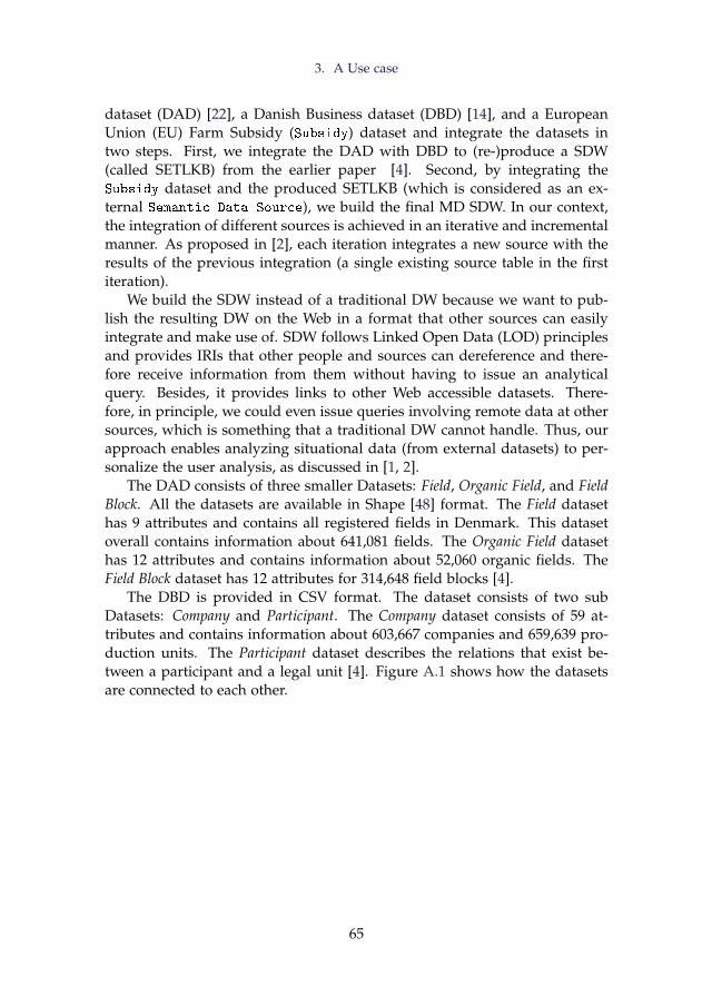
3. A Use case
dataset (DAD) [22], a Danish Business dataset (DBD) [14], and a EuropeanUnion (EU) Farm Subsidy (Subsidy) dataset and integrate the datasets intwo steps. First, we integrate the DAD with DBD to (re-)produce a SDW(called SETLKB) from the earlier paper [4]. Second, by integrating theSubsidy dataset and the produced SETLKB (which is considered as an ex-ternal Semantic Data Source), we build the final MD SDW. In our context,the integration of different sources is achieved in an iterative and incrementalmanner. As proposed in [2], each iteration integrates a new source with theresults of the previous integration (a single existing source table in the firstiteration).
We build the SDW instead of a traditional DW because we want to pub-lish the resulting DW on the Web in a format that other sources can easilyintegrate and make use of. SDW follows Linked Open Data (LOD) principlesand provides IRIs that other people and sources can dereference and there-fore receive information from them without having to issue an analyticalquery. Besides, it provides links to other Web accessible datasets. There-fore, in principle, we could even issue queries involving remote data at othersources, which is something that a traditional DW cannot handle. Thus, ourapproach enables analyzing situational data (from external datasets) to per-sonalize the user analysis, as discussed in [1, 2].
The DAD consists of three smaller Datasets: Field, Organic Field, and FieldBlock. All the datasets are available in Shape [48] format. The Field datasethas 9 attributes and contains all registered fields in Denmark. This datasetoverall contains information about 641,081 fields. The Organic Field datasethas 12 attributes and contains information about 52,060 organic fields. TheField Block dataset has 12 attributes for 314,648 field blocks [4].
The DBD is provided in CSV format. The dataset consists of two subDatasets: Company and Participant. The Company dataset consists of 59 at-tributes and contains information about 603,667 companies and 659,639 pro-duction units. The Participant dataset describes the relations that exist be-tween a participant and a legal unit [4]. Figure A.1 shows how the datasetsare connected to each other.
65
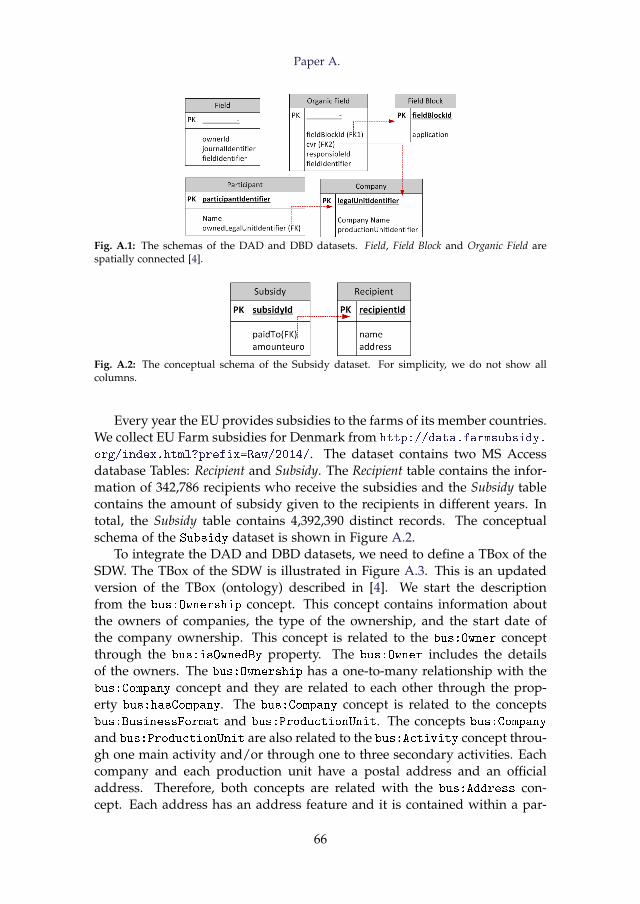
Paper A.
Fig. A.1: The schemas of the DAD and DBD datasets. Field, Field Block and Organic Field arespatially connected [4].
Fig. A.2: The conceptual schema of the Subsidy dataset. For simplicity, we do not show allcolumns.
Every year the EU provides subsidies to the farms of its member countries.We collect EU Farm subsidies for Denmark from http://data.farmsubsidy.
org/index.html?prefix=Raw/2014/. The dataset contains two MS Accessdatabase Tables: Recipient and Subsidy. The Recipient table contains the infor-mation of 342,786 recipients who receive the subsidies and the Subsidy tablecontains the amount of subsidy given to the recipients in different years. Intotal, the Subsidy table contains 4,392,390 distinct records. The conceptualschema of the Subsidy dataset is shown in Figure A.2.
To integrate the DAD and DBD datasets, we need to define a TBox of theSDW. The TBox of the SDW is illustrated in Figure A.3. This is an updatedversion of the TBox (ontology) described in [4]. We start the descriptionfrom the bus:Ownership concept. This concept contains information aboutthe owners of companies, the type of the ownership, and the start date ofthe company ownership. This concept is related to the bus:Owner conceptthrough the bus:isOwnedBy property. The bus:Owner includes the detailsof the owners. The bus:Ownership has a one-to-many relationship with thebus:Company concept and they are related to each other through the prop-erty bus:hasCompany. The bus:Company concept is related to the conceptsbus:BusinessFormat and bus:ProductionUnit. The concepts bus:Company
and bus:ProductionUnit are also related to the bus:Activity concept throu-gh one main activity and/or through one to three secondary activities. Eachcompany and each production unit have a postal address and an officialaddress. Therefore, both concepts are related with the bus:Address con-cept. Each address has an address feature and it is contained within a par-
66
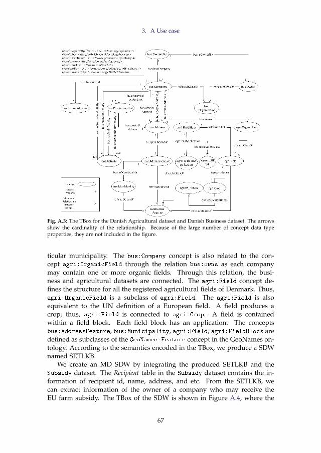
3. A Use case
Fig. A.3: The TBox for the Danish Agricultural dataset and Danish Business dataset. The arrowsshow the cardinality of the relationship. Because of the large number of concept data typeproperties, they are not included in the figure.
ticular municipality. The bus:Company concept is also related to the con-cept agri:OrganicField through the relation bus:owns as each companymay contain one or more organic fields. Through this relation, the busi-ness and agricultural datasets are connected. The agri:Field concept de-fines the structure for all the registered agricultural fields of Denmark. Thus,agri:OrganicField is a subclass of agri:Field. The agri:Field is alsoequivalent to the UN definition of a European field. A field produces acrop, thus, agri:Field is connected to agri:Crop. A field is containedwithin a field block. Each field block has an application. The conceptsbus:AddressFeature, bus:Municipality, agri:Field, agri:FieldBlock aredefined as subclasses of the GeoNames:Feature concept in the GeoNames on-tology. According to the semantics encoded in the TBox, we produce a SDWnamed SETLKB.
We create an MD SDW by integrating the produced SETLKB and theSubsidy dataset. The Recipient table in the Subsidy dataset contains the in-formation of recipient id, name, address, and etc. From the SETLKB, wecan extract information of the owner of a company who may receive theEU farm subsidy. The TBox of the SDW is shown in Figure A.4, where the
67
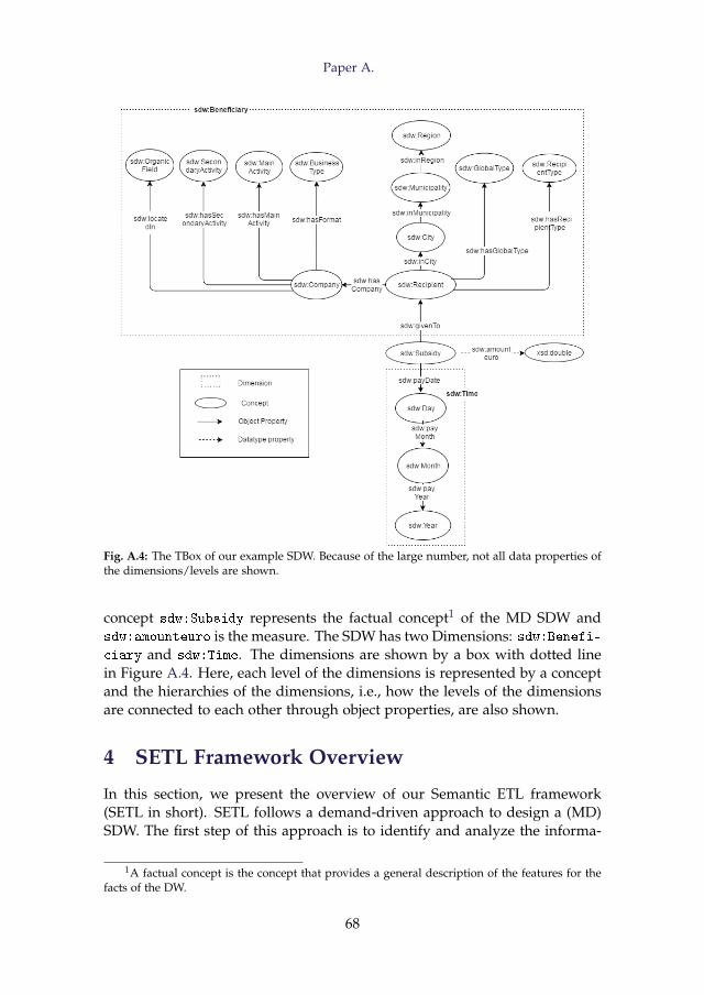
Paper A.
Fig. A.4: The TBox of our example SDW. Because of the large number, not all data properties ofthe dimensions/levels are shown.
concept sdw:Subsidy represents the factual concept1 of the MD SDW andsdw:amounteuro is the measure. The SDW has two Dimensions: sdw:Benefi-ciary and sdw:Time. The dimensions are shown by a box with dotted linein Figure A.4. Here, each level of the dimensions is represented by a conceptand the hierarchies of the dimensions, i.e., how the levels of the dimensionsare connected to each other through object properties, are also shown.
4 SETL Framework Overview
In this section, we present the overview of our Semantic ETL framework(SETL in short). SETL follows a demand-driven approach to design a (MD)SDW. The first step of this approach is to identify and analyze the informa-
1A factual concept is the concept that provides a general description of the features for thefacts of the DW.
68
4. SETL Framework Overview
tion requirements of business users and decision makers. Then, based on thegathered requirements, the next two steps of the DW are to build the DWschema and to build the ETL [23]. As the data in a SDW should be seman-tically connected, we assume the SDW to be a KB and it allows to producean MD schema for the SDW to benefit from OLAP. The semantic ETL pro-cess populates the SDW from the data sources according to the semanticscaptured in the schema.
Our discussion focuses on SETL’s architecture and its main componentsthat support the different steps of creating a SDW. Requirement engineer-ing (RE) is the process of identifying the needs of involved stakeholders andmodeling and documenting those requirements in a form that is comprehen-sible, analyzable and communicable [34]. RE in the DW is itself a researchtopic and it is beyond the scope of this paper. We direct readers to [23, 34]for RE. The main steps that SETL supports are: defining a TBox for the SDWbased on the domain of interest, extracting data from multiple heterogeneousdata sources, transforming the source data into RDF triples according to thetarget TBox, linking the data internally and externally, and loading the datainto a triple store, and/or publishing the data on the Web as Linked Data(LD).
Figure A.5 illustrates how the components of SETL framework are con-nected to each other. We divide the framework into three Layers: Defini-tion Layer, ETL Layer, and Data Warehouse Layer. The red-colored dashedlines in Figure A.5 separate the layers. In the Definition Layer, the SDWschema, sources, and the mappings among the sources and the target are de-fined. The SDW TBox Definition component is used to define a TBox describ-ing the relevant data and the SDW schema based on the requirements. Thesub-component QB4OLAP is used to define the MD semantics of the SDW.Using the Define Mapping component, the user can define the mappings be-tween a source TBox and the target TBox. To map between a Non Semantic
Data Source and the target TBox, the TBox Extraction component generatesa TBox representing the Non Semantic Data Source. In the ETL Layer, anETL process to populate the SDW from sources are designed. The Extractioncomponent extracts data from multiple sources, the Traditional Transformationcomponent cleanses and formats (e.g., unique value generation, null valuehandling, noisy data filtering etc.) the extracted data and stores them in aStaging Area. The Staging Area is a storage used to keep the intermedi-ate results of the ETL sub-processes. Then, the Semantic Transformation con-verts the data into RDF triples according to the target TBox. As a sub-taskSemantic Transformation stores the meta information of concepts, properties,instances, and IRIs used in the SDW into the Provenance Graph. The Exter-nal Linking component links the resources in the created RDF dataset to otherexternal resources. The SaveToFile component writes the created RDF datasetinto a file on disk. Finally, the Load component can either directly load the
69
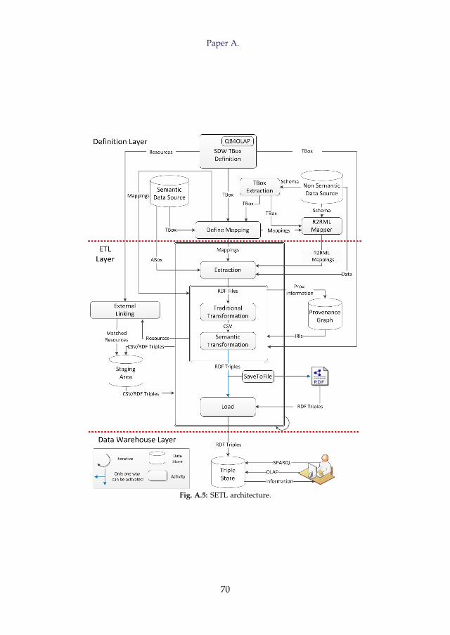
Paper A.
Fig. A.5: SETL architecture.
70
5. Definition Layer
RDF triples created by the Semantic Transformation component or load fromthe RDF dump file into the triple store, which can directly be queriedby the user. Extraction-Transformation-Load is an iterative block repeatedfor each ETL flow (shown as a curved arrow in Figure A.5). The Data Ware-house Layer concerns where the transformed semantic data should be stored.SPARQL queries can be used to analyze the stored data. The SDW definedin MD fashion can also be integrated with an OLAP tools to perform OLAPqueries. Here, we focus on building an ETL process. The following sectionsdescribe the Definition Layer and ETL Layer along with their components inmore details.
5 Definition Layer
In this section, we describe the Definition Layer of SETL. This layer integratesdifferent components required to define the schema of a SDW, to define thedifferent sources that feed data in the SDW, and to define the mappings be-tween the sources and the target. The following sections describe the differentcomponents of the Definition Layer.
5.1 SDW TBox Definition
The data in a SDW are semantically connected with other internal and/orexternal data. Therefore, capturing the semantics of the data at the concep-tual level is indispensable. SETL uses ontological constructs to design a SDW(in our context the SDW TBox) because of the following reasons. First, on-tologies allow for a semantic integration of disparate data sources as we canexplicitly define how two concepts of an ontology are structurally related andhow they are associated with different properties. Second, given the cubesshare dimensions, it facilitates drill-across operations [3] by basic graph op-erations during the integration of cubes. Third, it is machine-readable andallows us to automate the ETL modelling tasks. Fourth, compared to otherrepresentations, it is easier to evolve the DW. Fifth, it allows to preserve thesemantics of the Semantic Data Sources.
As mentioned in Section 2, some standard languages, such as RDFS orOWL can be used to describe a TBox. They both provide basic constructs todefine the formal semantics of the TBox. OWL uses owl:Class and rdfs:Prop
erty to define concepts and properties of the TBox, uses rdfs:subClassOf
and rdfs:subPropertyOf to define hierarchical relationships among conceptsand among properties, respectively, and uses rdfs:domain and rdfs:range
to associate properties with concepts.On-Line Analytical Processing (OLAP) is a technology to analyze the data
available in a DW to support decision making [59]. As OLAP is on-line, it
71
Paper A.
should provide answers quickly. To enable OLAP queries, the DW is rep-resented using the MD model. The central attraction of the MD model of abusiness is its simplicity and the easy and intuitive way of making analyticalqueries [29]. In the MD model, data are viewed in an n-dimensional space,usually known as a data cube, composed of facts (the cells of the cube) anddimensions (the axes of the cube). A fact is the interesting thing or processto be analyzed (for example, analysis of subsidy given by the EU) and theattributes of the fact are called measures (e.g., amount of subsidy), usuallyrepresented as numeric values. A dimensions is organized into hierarchies,composed of a number of levels, which permit users to explore and aggre-gate measures at various levels of detail. For example, the Address hierarchy(recipient→ Municipality→ Region→ Country) of the Beneficiary dimensionallows to aggregate the subsidy amount at various levels of detail. Therefore,to enable OLAP, we support the MD representation of the SDW.
Although the version of the framework described in the workshop pa-per [17] allows to define a TBox using OWL, it does not support to define MDconstructs. We extend this version by adding the QB4OLAP sub-componentto support MD constructs. To describe the MD semantics at the TBox level,we use the QB4OLAP vocabulary [20]. QB4OLAP is used to annotate theTBox with MD constructs and is based on the RDF Data Cube (QB) whichis the W3C standard to publish MD data on the Web [15]. The QB is mostlyused for analyzing statistical data and does not adequately support OLAPMD constructs. Therefore, we direct to QB4OLAP. Figure A.6 depicts theQB4OLAP vocabulary [20]. The terms prefixed with “qb:” are from the orig-inal QB vocabulary, and QB4OLAP terms are prefixed with “qb4o:” and dis-played with gray background. Capitalized terms represent RDF classes, andnon-capitalized terms represent RDF properties. Capitalized terms in italicsrepresent classes with no instances. An arrow with black triangle head fromclass A to class B, labeled pro means that pro is an RDF property with domainA and range B. White triangles represent sub-classes or sub-properties.
In QB4OLAP, the concept qb:DataStructureDefinition is used to de-fine the structure of a cube in terms of dimensions, measures, and attributes.To define dimensions, levels, level-attributes and hierarchies, the conceptsqb4o:DimensionProperty, qb4o:LevelProperty, qb4o:LevelAttribute, andqb4o:Hierarchy are used, respectively. The association between a level-attribute and a level is defined by qb4o:hasAttribute property. The hier-archies are connected with dimensions via the property qb4o:hasHierarchy.Hierarchies are composed of pairs of levels, which are defined by the con-cept qb4o:HierarchyStep. The reason of defining the hierarchy as a col-lection of pairs is to establish a rollup relationship between the levels of apair. A rollup relation is defined by qb4o:RollupProperty and the cardinal-ity of the rollup relation is stated using the qb4o:pcCardinality. Each pairof levels is connected to a rollup relation via qb4o:rollup. The role of the
72
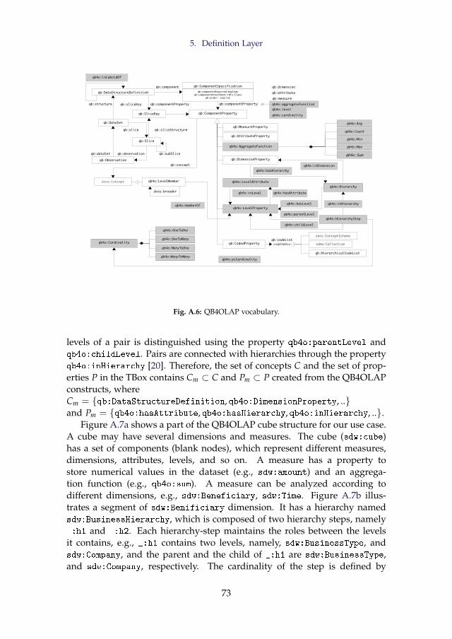
5. Definition Layer
qb:DataSet
qb:Observation
qb:Slice
qb:SliceKey
qb:AttributeProperty
qb:MeasureProperty
qb:CodedProperty
skos:ConceptScheme
sdmx:Collection
skos:Concept
qb:codeList
qb:sliceKeyqb:structure
qb:dataSet qb:observation
qb:sliceStructureqb:slice
qb:componentProperty
qb:concept
qb:ComponentProperty
qb:componentProperty
qb:subSlice
qb4o:LevelMember
qb4o:AggregateFunction
qb4o:memberOf
skos:broader
qb:HierarchicalCodeList
<<union>>
qb:DimensionProperty
qb4o:hasLevel
qb4o:hasHierarchyqb4o:inDimension
qb:component
qb4o:Max
qb4o:Avg
qb4o:Count
qb4o:Min
qb4o:Sum
qb4o:Cardinality
qb4o:OneToOne
qb4o:OneToMany
qb4o:ManyToOne
qb:ComponentSpecification
qb:componentRequired:booleanqb:componentAttachment:rdfs:Class
qb:order: xsd:int
qb4o:pcCardinality
qb4o:HierarchyStep
qb4o:ManyToMany
qb4o:childLevel
qb4o:parentLevel
qb:dimension
qb:attribute
qb:measure
qb4o:level
qb4o:cardinality
qb4o:aggregateFunction
qb4o:hasAttribute
qb4o:isCuboidOf
qb4o:Hierarchy
qb4o:inHierarchyqb4o:LevelProperty
qb4o:LevelAttribute
qb4o:inLevel
qb:DataStructureDefinition
Fig. A.6: QB4OLAP vocabulary.
levels of a pair is distinguished using the property qb4o:parentLevel andqb4o:childLevel. Pairs are connected with hierarchies through the propertyqb4o:inHierarchy [20]. Therefore, the set of concepts C and the set of prop-erties P in the TBox contains Cm ⊂ C and Pm ⊂ P created from the QB4OLAPconstructs, whereCm = {qb:DataStructureDefinition, qb4o:DimensionProperty, ..}and Pm = {qb4o:hasAttribute, qb4o:hasHierarchy, qb4o:inHierarchy, ..}.
Figure A.7a shows a part of the QB4OLAP cube structure for our use case.A cube may have several dimensions and measures. The cube (sdw:cube)has a set of components (blank nodes), which represent different measures,dimensions, attributes, levels, and so on. A measure has a property tostore numerical values in the dataset (e.g., sdw:amount) and an aggrega-tion function (e.g., qb4o:sum). A measure can be analyzed according todifferent dimensions, e.g., sdw:Beneficiary, sdw:Time. Figure A.7b illus-trates a segment of sdw:Benificiary dimension. It has a hierarchy namedsdw:BusinessHierarchy, which is composed of two hierarchy steps, namely_:h1 and _:h2. Each hierarchy-step maintains the roles between the levelsit contains, e.g., _:h1 contains two levels, namely, sdw:BusinessType, andsdw:Company, and the parent and the child of _:h1 are sdw:BusinessType,and sdw:Company, respectively. The cardinality of the step is defined by
73
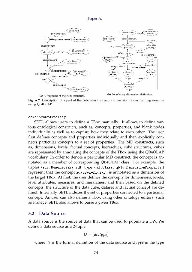
Paper A.
(a) A fragment of the cube structure. (b) Beneficiary dimension definition.
Fig. A.7: Description of a part of the cube structure and a dimension of our running exampleusing QB4OLAP.
qb4o:pcCardinality.SETL allows users to define a TBox manually. It allows to define var-
ious ontological constructs, such as, concepts, properties, and blank nodesindividually as well as to capture how they relate to each other. The userfirst defines concepts and properties individually and then explicitly con-nects particular concepts to a set of properties. The MD constructs, suchas, dimensions, levels, factual concepts, hierarchies, cube structures, cubesare represented by annotating the concepts of the TBox using the QB4OLAPvocabulary. In order to denote a particular MD construct, the concept is an-notated as a member of corresponding QB4OLAP class. For example, thetriples (sdw:Beneficiary rdf:type owl:Class, qb4o:DimensionProperty.)represent that the concept sdw:Beneficiary is annotated as a dimension ofthe target TBox. At first, the user defines the concepts for dimensions, levels,level attributes, measures, and hierarchies, and then based on the definedconcepts, the structure of the data cube, dataset and factual concept are de-fined. Internally, SETL indexes the set of properties connected to a particularconcept. As user can also define a TBox using other ontology editors, suchas Protege, SETL also allows to parse a given TBox.
5.2 Data Source
A data source is the source of data that can be used to populate a DW. Wedefine a data source as a 2-tuple:
D = (ds, type)
where ds is the formal definition of the data source and type is the type
74
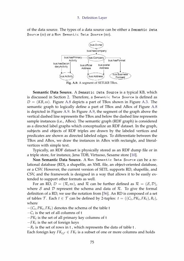
5. Definition Layer
of the data source. The types of a data source can be either a Semantic Data
Source (ss) or a Non Semantic Data Source (ns).
Fig. A.8: A segment of SETLKB TBox.
Semantic Data Source. A Semantic Data Source is a typical KB, whichis discussed in Section 2. Therefore, a Semantic Data Source is defined asD = (KB, ss). Figure A.8 depicts a part of TBox shown in Figure A.3. Thesemantic graph to logically define a part of TBox and ABox of Figure A.8is depicted in Figure A.9. In Figure A.9, the segment of the graph above thevertical dashed line represents the TBox and below the dashed line representssample instances (i.e., ABox). The semantic graph (RDF graph) is consideredas a directed label graphs which conceptualize an RDF dataset. In the graph,subjects and objects of RDF triples are drawn by the labeled vertices andpredicates are shown as directed labeled edges. To differentiate between theTBox and ABox, we draw the instances in ABox with rectangle, and literal-vertices with simple text.
Typically, an RDF dataset is physically stored as an RDF dump file or ina triple store, for instance, Jena TDB, Virtuoso, Sesame store [10].
Non Semantic Data Source. A Non Semantic Data Source can be a re-lational database (RD), a shapefile, an XML file, an object-oriented database,or a CSV. However, the current version of SETL supports RD, shapefile, andCSV, and the framework is designed in a way that allows it to be easily ex-tended to support other formats as well.
For an RD, D = (R, ns), and R can be further defined as R = (S ,D),where S and D represent the schema and data of R. To give the formaldefinition of a RD, we use the notation from [56]. An RD is composed of a setof tables T . Each t ∈ T can be defined by 2-tuples: t = ((Ct, PKt, FKt), Rt),where−(Ct, PKt, FKt) denotes the schema of the table t−Ct is the set of all columns of t−PKt is the set of all primary key columns of t−FKt is the set of foreign keys−Rt is the set of rows in t , which represents the data of table t .Each foreign key FKt,t′ ∈ FKt is a subset of one or more columns and holds
75
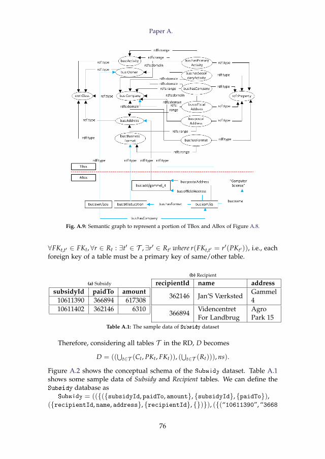
Paper A.
Fig. A.9: Semantic graph to represent a portion of TBox and ABox of Figure A.8.
∀FKt,t′ ∈ FKt, ∀r ∈ Rt : ∃t′ ∈ T , ∃r′ ∈ Rt′ where r(FKt,t′ = r′(PKt′)), i.e., eachforeign key of a table must be a primary key of same/other table.
(a) Subsidy
subsidyId paidTo amount10611390 366894 61730810611402 362146 6310
(b) Recipient
recipientId name address
362146 Jan’S VærkstedGammel4
366894VidencentretFor Landbrug
AgroPark 15
Table A.1: The sample data of Subsidy dataset
Therefore, considering all tables T in the RD, D becomes
D = ((⋃
t∈T (Ct, PKt, FKt)), (⋃
t∈T (Rt))), ns).
Figure A.2 shows the conceptual schema of the Subsidy dataset. Table A.1shows some sample data of Subsidy and Recipient tables. We can define theSubsidy database as
Subsidy = (({({subsidyId, paidTo, amount}, {subsidyId}, {paidTo}),({recipientId, name, address}, {recipientId}, {})}), ({(“10611390”, “3668
76
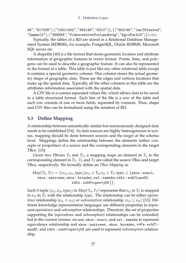
5. Definition Layer
94”, “617308”), (“10611402”, “362146”, “6310”)}, {(“362146”, “Jan′SVrksted”,“Gammel4”), (“366894”, “VidencentretForLandbrug”, “AgroPark15”)}), ns).
Typically, the tables of a RD are stored in a Relational Database Manage-ment System (RDBMS), for example, PostgreSQL, Oracle RDBMS, MicrosoftSQL server etc.
A shapefile [48] is a file format that stores geometric location and attributeinformation of geographic features in vector format. Points, lines, and poly-gons can be used to describe a geographic feature. It can also be representedin the format of a table. This table is just like any other relational table exceptit contains a special geometry column. This column stores the actual geome-try shape of geographic data. These are the edges and vertices locations thatmake up the spatial data. Typically, all the other columns in this table are theattributes information associated with the spatial data.
A CSV file is a comma separated values file, which allows data to be savedin a table structured format. Each line of the file is a row of the table andeach row consists of one or more fields, separated by commas. Thus, shapeand CSV files can be formalized using the notation of RD.
5.3 Define Mapping
A relationship between semantically similar but autonomously designed dataneeds to be established [54]. As data sources are highly heterogeneous in syn-tax, mapping should be done between sources and the target at the schemalevel. Mappings define the relationship between the elements (either con-cepts or properties) of a source and the corresponding elements in the targetTBox [18].
Given two TBoxes TS and TT , a mapping maps an element in TS to thecorresponding element in TT . TS and TT are called the source TBox and targetTBox, respectively. We formally define an TBox Mapping as
Map(TS, TT) = {(es1, et1, typei)|es1 ∈ TS, et1 ∈ TT , typei ∈ {skos : exact,skos : narrower, skos : broader, owl : sameAs, rdfs : subClassOf,
rdfs : subPropertyOf}}.
Each 3-tuple (es1, et1, typei) in Map(TS, TT) represents that es1 in TS is mappedto et1 in TT with the relationship typei. The relationship can be either equiva-lence relationship (es1 ≡ et1) or subsumption relationship (es1 v et1) [33]. Dif-ferent knowledge representation languages use different properties to repre-sent equivalence and subsumption relationships. Therefore, the set of propertiessupporting the (equivalence and subsumption) relationships can be extended,but in the current version, we use, skos : exact, and owl : sameAs to representequivalence relationship and skos : narrower, skos : broader, rdfs:subCl-assOf, and rdfs : subPropertyOf are used to represent subsumption relation-ship.
77
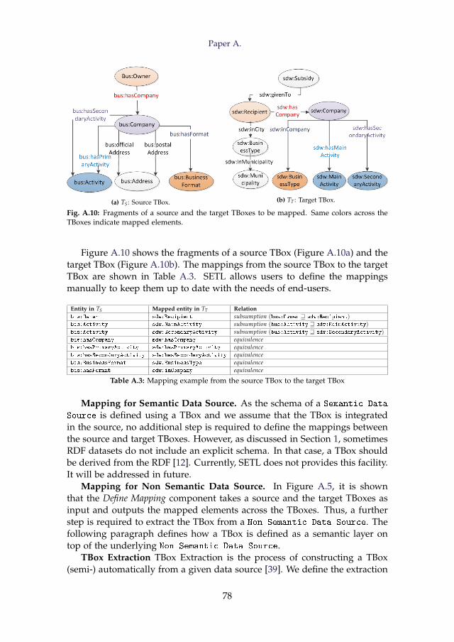
Paper A.
(a) TS : Source TBox. (b) TT : Target TBox.
Fig. A.10: Fragments of a source and the target TBoxes to be mapped. Same colors across theTBoxes indicate mapped elements.
Figure A.10 shows the fragments of a source TBox (Figure A.10a) and thetarget TBox (Figure A.10b). The mappings from the source TBox to the targetTBox are shown in Table A.3. SETL allows users to define the mappingsmanually to keep them up to date with the needs of end-users.
Entity in TS Mapped entity in TT Relationbus:Owner sdw:Recipient subsumption (bus:Owner w sdw:Recipient)bus:Activity sdw:MainActivity subsumption (bus:Activity w sdw:MainActivity)bus:Activity sdw:SecondaryActivity subsumption (bus:Activity w sdw:SecondaryActivity)bus:hasCompany sdw:hasCompany equivalencebus:hasPrimaryActivity sdw:hasPrimaryActivity equivalencebus:hasSecondaryActivity sdw:hasSecondaryActivity equivalencebus:BusinessFormat sdw:BusinessType equivalencebus:hasFormat sdw:inCompany equivalence
Table A.3: Mapping example from the source TBox to the target TBox
Mapping for Semantic Data Source. As the schema of a Semantic Data
Source is defined using a TBox and we assume that the TBox is integratedin the source, no additional step is required to define the mappings betweenthe source and target TBoxes. However, as discussed in Section 1, sometimesRDF datasets do not include an explicit schema. In that case, a TBox shouldbe derived from the RDF [12]. Currently, SETL does not provides this facility.It will be addressed in future.
Mapping for Non Semantic Data Source. In Figure A.5, it is shownthat the Define Mapping component takes a source and the target TBoxes asinput and outputs the mapped elements across the TBoxes. Thus, a furtherstep is required to extract the TBox from a Non Semantic Data Source. Thefollowing paragraph defines how a TBox is defined as a semantic layer ontop of the underlying Non Semantic Data Source.
TBox Extraction TBox Extraction is the process of constructing a TBox(semi-) automatically from a given data source [39]. We define the extraction
78
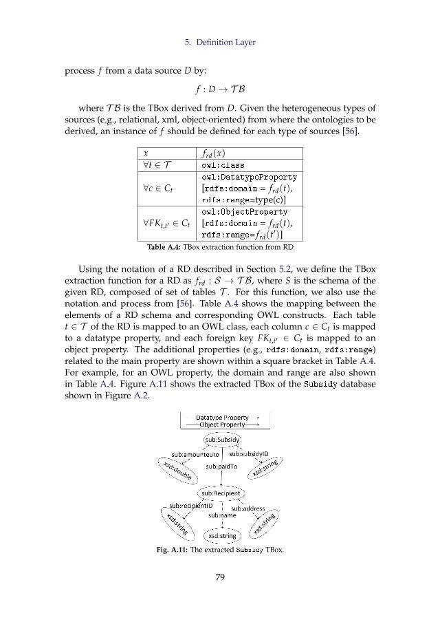
5. Definition Layer
process f from a data source D by:
f : D → T B
where T B is the TBox derived from D. Given the heterogeneous types ofsources (e.g., relational, xml, object-oriented) from where the ontologies to bederived, an instance of f should be defined for each type of sources [56].
x frd(x)∀t ∈ T owl:class
∀c ∈ Ct
owl:DatatypeProperty
[rdfs:domain = frd(t),rdfs:range=type(c)]
∀FKt,t′ ∈ Ct
owl:ObjectProperty
[rdfs:domain = frd(t),rdfs:range= frd(t′)]
Table A.4: TBox extraction function from RD
Using the notation of a RD described in Section 5.2, we define the TBoxextraction function for a RD as frd : S → T B, where S is the schema of thegiven RD, composed of set of tables T . For this function, we also use thenotation and process from [56]. Table A.4 shows the mapping between theelements of a RD schema and corresponding OWL constructs. Each tablet ∈ T of the RD is mapped to an OWL class, each column c ∈ Ct is mappedto a datatype property, and each foreign key FKt,t′ ∈ Ct is mapped to anobject property. The additional properties (e.g., rdfs:domain, rdfs:range)related to the main property are shown within a square bracket in Table A.4.For example, for an OWL property, the domain and range are also shownin Table A.4. Figure A.11 shows the extracted TBox of the Subsidy databaseshown in Figure A.2.
Fig. A.11: The extracted Subsidy TBox.
79
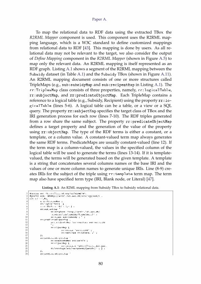
Paper A.
To map the relational data to RDF data using the extracted TBox theR2RML Mapper component is used. This component uses the R2RML map-ping language, which is a W3C standard to define customized mappingsfrom relational data to RDF [43]. This mapping is done by users. As all re-lational data may not be relevant to the target, we also consider the outputof Define Mapping component in the R2RML Mapper (shown in Figure A.5) tomap only the relevant data. An R2RML mapping is itself represented as anRDF graph. Listing A.1 shows a segment of the R2RML mapping between theSubsidy dataset (in Table A.1) and the Subsidy TBox (shown in Figure A.11).An R2RML mapping document consists of one or more structures calledTripleMaps (e.g., sub:subsidyMap and sub:recipentMap in Listing A.1). Therr:TriplesMap class consists of three properties, namely, rr:logicalTable,rr:subjectMap, and rr:predicateObjectMap. Each TripleMap contains areference to a logical table (e.g., Subsidy, Recipient) using the property rr:lo-
gicalTable (lines 5-6). A logical table can be a table, or a view or a SQLquery. The property rr:subjectMap specifies the target class of TBox and theIRI generation process for each row (lines 7-10). The RDF triples generatedfrom a row share the same subject. The property rr:predicateObjectMap
defines a target property and the generation of the value of the propertyusing rr:objectMap. The type of the RDF terms is either a constant, or atemplate, or a column value. A constant-valued term map always generatesthe same RDF terms. PredicateMaps are usually constant-valued (line 12). Ifthe term map is a column-valued, the values in the specified column of thelogical table will be used to generate the terms (lines 13-14). If it is template-valued, the terms will be generated based on the given template. A templateis a string that concatenates several columns names or the base IRI and thevalues of one or more column names to generate unique IRIs. Line (8-9) cre-ates IRIs for the subject of the triple using rr:template term map. The termmap also have specified term type (IRI, Blank node, or Literal) [47].
Listing A.1: An R2ML mapping from Subsidy TBox to Subsidy relational data.
1 @prefix rr: <http ://www.w3.org/ns/r2rml\#>.
2 @prefix sub: <$http :// extbi.lab.aau.dk/ontology/sub/> .
3 sub:subsidyMap
4 a rr:TriplesMap ;
5 rr:logicalTable [
6 rr:tableName 'Subsidy ' ] ;
7 rr:subjectMap [
8 rr:template 'http :// extbi.lab.aau.dk/
9 ontology/sub/subsidy /{ subsidyId}' ;
10 rr:class sub:Subsidy ; ] ;
11 rr:predicateObjectMap [
12 rr:predicateMap [rr:constant sub:subsidId
13 ];
14 rr:objectMap [
15 rr:column 'subsidyId ' ;
16 rr:termType rr:Literal ;] ;
17 ];
18 rr:predicateObjectMap [
19 rr:predicateMap sub:paidTo ;
20 rr:objectMap [
21 rr:template 'http :// extbi.lab.aau.
22 dk/ontology/sub/recipient /{ paidTo}' ; ] ;
23 ];
24 rr:predicateObjectMap [
80
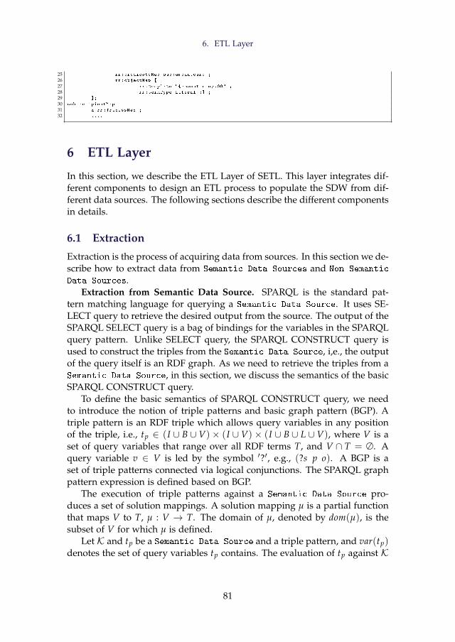
6. ETL Layer
25 rr:predicateMap sub:amounteuro ;
26 rr:objectMap [
27 rr:template "{amounteuro }.00" ;
28 rr:termType Literal ;] ;
29 ];
30 sub:recipientMap
31 a rr:TriplesMap ;
32 ....
6 ETL Layer
In this section, we describe the ETL Layer of SETL. This layer integrates dif-ferent components to design an ETL process to populate the SDW from dif-ferent data sources. The following sections describe the different componentsin details.
6.1 Extraction
Extraction is the process of acquiring data from sources. In this section we de-scribe how to extract data from Semantic Data Sources and Non Semantic
Data Sources.Extraction from Semantic Data Source. SPARQL is the standard pat-
tern matching language for querying a Semantic Data Source. It uses SE-LECT query to retrieve the desired output from the source. The output of theSPARQL SELECT query is a bag of bindings for the variables in the SPARQLquery pattern. Unlike SELECT query, the SPARQL CONSTRUCT query isused to construct the triples from the Semantic Data Source, i,e., the outputof the query itself is an RDF graph. As we need to retrieve the triples from aSemantic Data Source, in this section, we discuss the semantics of the basicSPARQL CONSTRUCT query.
To define the basic semantics of SPARQL CONSTRUCT query, we needto introduce the notion of triple patterns and basic graph pattern (BGP). Atriple pattern is an RDF triple which allows query variables in any positionof the triple, i.e., tp ∈ (I ∪ B ∪ V)× (I ∪ V)× (I ∪ B ∪ L ∪ V), where V is aset of query variables that range over all RDF terms T, and V ∩ T = ∅. Aquery variable v ∈ V is led by the symbol ′?′, e.g., (?s p o). A BGP is aset of triple patterns connected via logical conjunctions. The SPARQL graphpattern expression is defined based on BGP.
The execution of triple patterns against a Semantic Data Source pro-duces a set of solution mappings. A solution mapping µ is a partial functionthat maps V to T, µ : V → T. The domain of µ, denoted by dom(µ), is thesubset of V for which µ is defined.
Let K and tp be a Semantic Data Source and a triple pattern, and var(tp)denotes the set of query variables tp contains. The evaluation of tp against K
81
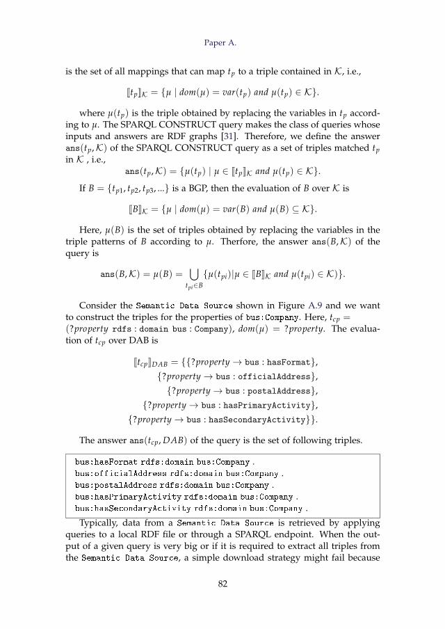
Paper A.
is the set of all mappings that can map tp to a triple contained in K, i.e.,
JtpKK = {µ | dom(µ) = var(tp) and µ(tp) ∈ K}.
where µ(tp) is the triple obtained by replacing the variables in tp accord-ing to µ. The SPARQL CONSTRUCT query makes the class of queries whoseinputs and answers are RDF graphs [31]. Therefore, we define the answerans(tp,K) of the SPARQL CONSTRUCT query as a set of triples matched tpin K , i.e.,
ans(tp,K) = {µ(tp) | µ ∈ JtpKK and µ(tp) ∈ K}.
If B = {tp1, tp2, tp3, ...} is a BGP, then the evaluation of B over K is
JBKK = {µ | dom(µ) = var(B) and µ(B) ⊆ K}.
Here, µ(B) is the set of triples obtained by replacing the variables in thetriple patterns of B according to µ. Therfore, the answer ans(B,K) of thequery is
ans(B,K) = µ(B) =⋃
tpi∈B{µ(tpi)|µ ∈ JBKK and µ(tpi) ∈ K)}.
Consider the Semantic Data Source shown in Figure A.9 and we wantto construct the triples for the properties of bus:Company. Here, tcp =(?property rdfs : domain bus : Company), dom(µ) = ?property. The evalua-tion of tcp over DAB is
JtcpKDAB = {{?property→ bus : hasFormat},{?property→ bus : officialAddress},{?property→ bus : postalAddress},
{?property→ bus : hasPrimaryActivity},{?property→ bus : hasSecondaryActivity}}.
The answer ans(tcp, DAB) of the query is the set of following triples.
bus:hasFormat rdfs:domain bus:Company .bus:officialAddress rdfs:domain bus:Company .bus:postalAddress rdfs:domain bus:Company .bus:hasPrimaryActivity rdfs:domain bus:Company .bus:hasSecondaryActivity rdfs:domain bus:Company .
Typically, data from a Semantic Data Source is retrieved by applyingqueries to a local RDF file or through a SPARQL endpoint. When the out-put of a given query is very big or if it is required to extract all triples fromthe Semantic Data Source, a simple download strategy might fail because
82
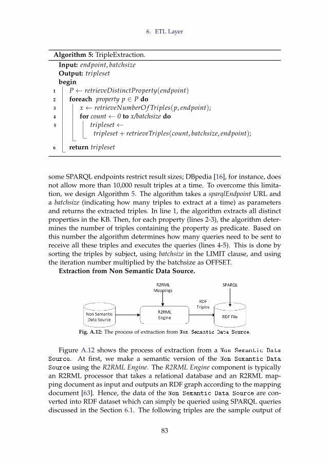
6. ETL Layer
Algorithm 5: TripleExtraction.Input: endpoint, batchsizeOutput: triplesetbegin
1 P← retrieveDistinctProperty(endpoint)2 foreach property p ∈ P do3 x ← retrieveNumberO f Triples(p, endpoint);4 for count← 0 to x/batchsize do5 tripleset←
tripleset + retrieveTriples(count, batchsize, endpoint);
6 return tripleset
some SPARQL endpoints restrict result sizes; DBpedia [16], for instance, doesnot allow more than 10,000 result triples at a time. To overcome this limita-tion, we design Algorithm 5. The algorithm takes a sparqlEndpoint URL anda batchsize (indicating how many triples to extract at a time) as parametersand returns the extracted triples. In line 1, the algorithm extracts all distinctproperties in the KB. Then, for each property (lines 2-3), the algorithm deter-mines the number of triples containing the property as predicate. Based onthis number the algorithm determines how many queries need to be sent toreceive all these triples and executes the queries (lines 4-5). This is done bysorting the triples by subject, using batchsize in the LIMIT clause, and usingthe iteration number multiplied by the batchsize as OFFSET.
Extraction from Non Semantic Data Source.
Fig. A.12: The process of extraction from Non Semantic Data Source.
Figure A.12 shows the process of extraction from a Non Semantic Data
Source. At first, we make a semantic version of the Non Semantic Data
Source using the R2RML Engine. The R2RML Engine component is typicallyan R2RML processor that takes a relational database and an R2RML map-ping document as input and outputs an RDF graph according to the mappingdocument [63]. Hence, the data of the Non Semantic Data Source are con-verted into RDF dataset which can simply be queried using SPARQL queriesdiscussed in the Section 6.1. The following triples are the sample output of
83
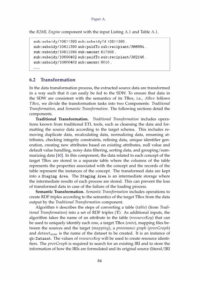
Paper A.
the R2ML Engine component with the input Listing A.1 and Table A.1.
sub:subsidy/10611390 sub:subsidyId 10611390 .sub:subsidy/10611390 sub:paidTo sub:recipient/366894 .sub:subsidy/10611390 sub:amount 617308 .sub:subsidy/10600402 sub:paidTo sub:recipient/362146 .sub:subsidy/10600402 sub:amount 6010 .......
6.2 Transformation
In the data transformation process, the extracted source data are transformedin a way such that it can easily be fed to the SDW. To ensure that data inthe SDW are consistent with the semantics of its TBox, i.e., ABox followsTBox, we divide the transformation tasks into two Components: TraditionalTransformation, and Semantic Transformation. The following sections detail thecomponents.
Traditional Transformation. Traditional Transformation includes opera-tions known from traditional ETL tools, such as cleansing the data and for-matting the source data according to the target schema. This includes re-moving duplicate data, recalculating data, normalizing data, renaming at-tributes, checking integrity constraints, refining data, unique identifier gen-eration, creating new attributes based on existing attributes, null value anddefault value handling, noisy data filtering, sorting data, and grouping/sum-marizing data [40]. In this component, the data related to each concept of thetarget TBox are stored in a separate table where the columns of the tablerepresents the properties associated with the concept and the records of thetable represent the instances of the concept. The transformed data are keptinto a Staging Area. The Staging Area is an intermediate storage wherethe intermediate results of each process are stored. This can prevent the lossof transformed data in case of the failure of the loading process.
Semantic Transformation. Semantic Transformation includes operations tocreate RDF triples according to the semantics of the target TBox from the dataoutput by the Traditional Transformation component.
Algorithm 6 describes the steps of converting a table (table) (from Tradi-tional Transformation) into a set of RDF triples (T). As additional inputs, thealgorithm takes the name of an attribute in the table (resourceKey) that canbe used to uniquely identify each row, a target TBox (onto), mapping files be-tween the sources and the target (mapping), a provenance graph (provGraph)and datasetname is the name of the dataset to be created. It is an instance ofqb:Dataset. The values of resourceKey will be used to create resource identi-fiers. The provGraph is required to search for an existing IRI and to store theinformation of how the IRIs are formulated and its original source (literal/IRI
84
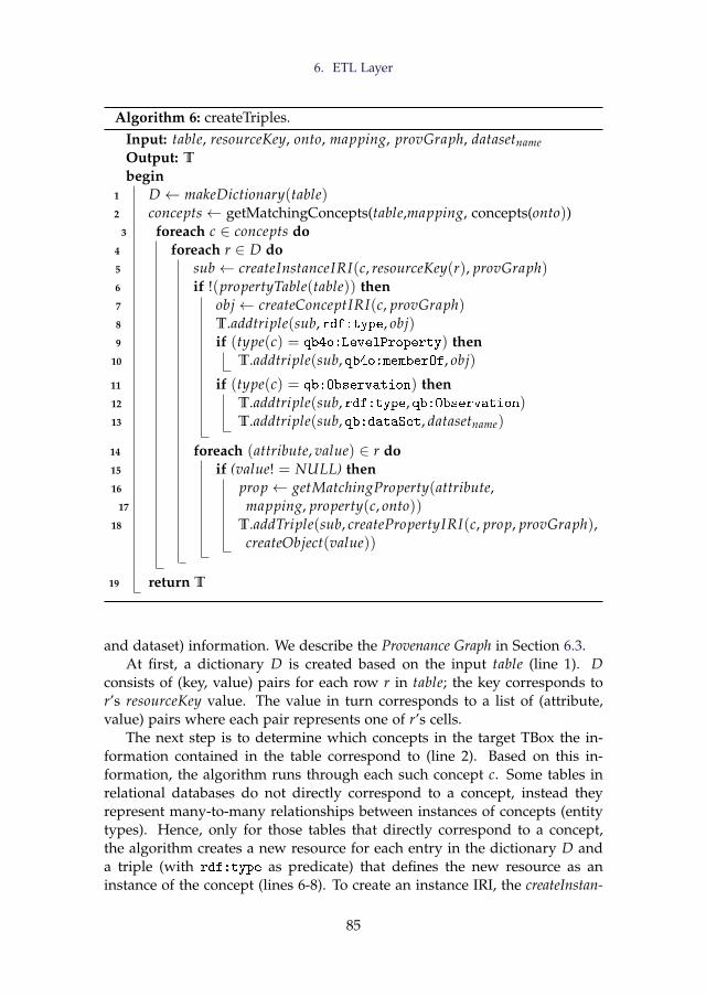
6. ETL Layer
Algorithm 6: createTriples.Input: table, resourceKey, onto, mapping, provGraph, datasetnameOutput: T
begin1 D ← makeDictionary(table)2 concepts← getMatchingConcepts(table,mapping, concepts(onto))
3 foreach c ∈ concepts do4 foreach r ∈ D do5 sub← createInstanceIRI(c, resourceKey(r), provGraph)6 if !(propertyTable(table)) then7 obj← createConceptIRI(c, provGraph)8 T.addtriple(sub, rdf:type, obj)9 if (type(c) = qb4o:LevelProperty) then
10 T.addtriple(sub, qb4o:memberOf, obj)
11 if (type(c) = qb:Observation) then12 T.addtriple(sub, rdf:type, qb:Observation)13 T.addtriple(sub, qb:dataSet, datasetname)
14 foreach (attribute, value) ∈ r do15 if (value! = NULL) then16 prop← getMatchingProperty(attribute,
17 mapping, property(c, onto))18 T.addTriple(sub, createPropertyIRI(c, prop, provGraph),
createObject(value))
19 return T
and dataset) information. We describe the Provenance Graph in Section 6.3.At first, a dictionary D is created based on the input table (line 1). D
consists of (key, value) pairs for each row r in table; the key corresponds tor’s resourceKey value. The value in turn corresponds to a list of (attribute,value) pairs where each pair represents one of r’s cells.
The next step is to determine which concepts in the target TBox the in-formation contained in the table correspond to (line 2). Based on this in-formation, the algorithm runs through each such concept c. Some tables inrelational databases do not directly correspond to a concept, instead theyrepresent many-to-many relationships between instances of concepts (entitytypes). Hence, only for those tables that directly correspond to a concept,the algorithm creates a new resource for each entry in the dictionary D anda triple (with rdf:type as predicate) that defines the new resource as aninstance of the concept (lines 6-8). To create an instance IRI, the createInstan-
85
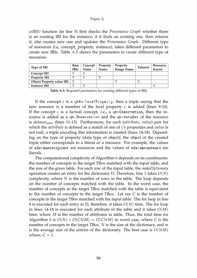
Paper A.
ceIRI() function (in line 5) first checks the Provenance Graph whether thereis an existing IRI for the instance; if it finds an existing one, then returnsit, else creates new one and updates the Provenance Graph. Different typeof resources (i.e, concept, property, instance), takes different parameters tocreate new IRIs. Table A.5 shows the parameters to create different type ofresources.
Type of IRIBaseIRIs
ConceptName
PropertyName
PropertyRange Name
Value(s)ResourceKey(s)
Concept IRI Y YProperty IRI Y Y YObject Property value IRI Y Y YInstance IRI Y Y Y
Table A.5: Required parameters for creating different types of IRIs
If the concept c is a qb4o:LevelProperty, then a triple saying that thenew resource is a member of the level property c is added (lines 9-10).If the concept c is a factual concept, i.e., a qb:Observation, then the re-source is added as a qb:Observation and the qb:dataSet of the resourceis datasetname (lines 11-13). Furthermore, for each (attribute, value) pair forwhich the attribute is defined as a match of one of c’s properties and value isnot null, a triple encoding this information is created (lines 14-18). Depend-ing on the type of property (data type or object), the object of the createdtriple either corresponds to a literal or a resource. For example, the valuesof sdw:hasrecipient are resources and the values of sdw:amounteuro areliterals.
The computational complexity of Algorithm 6 depends on its constituents:the number of concepts in the target TBox matched with the input table, andthe size of the given table. For each row of the input table, the makeDictionaryoperation creates an entry for the dictionary D. Therefore, line 1 takes O(N)complexity, where N is the number of rows in the table. The loop dependson the number of concepts matched with the table. In the worst case, thenumber of concepts in the target TBox matched with the table is equivalentto the number of concepts in the target TBox. Let say C is the number ofconcepts in the target TBox matched with the input table. The for loop in line4 is executed for each entry in D, therefore, it takes O(N) time. The for loopin lines 14-18 is executed for each attribute of the table and it takes O(M)time, where M is the number of attributes in table. Thus, the total time forAlgorithm 6 is O(N) + O(CNM) = O(CNM) in worst case, where C is thenumber of concepts in the target TBox, N is the size of the dictionary, and mis the average size of the entries of the dictionary. The best case is O(NM)where, C = 1.
86
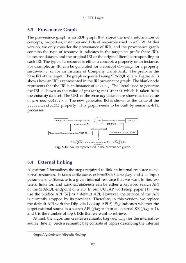
6. ETL Layer
6.3 Provenance Graph
The provenance graph is an RDF graph that stores the meta information ofconcepts, properties, instances and IRIs of resources used in a SDW. At thisversion, we only consider the provenance of IRIs, and the provenance graphcontains the type of resource it indicates in the target, its prefix (base IRI),its source dataset, and the original IRI or the original literal corresponding toeach IRI. The type of a resource is either a concept, a property or an instance.For example, an IRI can be generated for a concept Company, for a propertyhasCompany, or for an instance of Company DanskBank. The prefix is thebase IRI of the target. The graph is queried using SPARQL query. Figure A.13shows how an IRI is represented in the IRI provenance graph. The blank noderepresents that the IRI is an instance of sdw:Day. The literal used to generatethe IRI is shown as the value of pro:originalLiteral which is taken fromthe subsidy dataset. The URL of the subsidy dataset are shown as the valueof pro:sourcedataset. The new generated IRI is shown as the value of thepro:generatedIRI property. This graph needs to be built by semantic-ETLprocesses.
Fig. A.13: An IRI represented in the provenance graph.
6.4 External linking
Algorithm 7 formalizes the steps required to link an internal resource to ex-ternal resources. It takes intResource, externalDataSource flag, and k as inputparameters. intResource is a given internal resource that we want to find ex-ternal links for, and externalDataSource can be either a keyword search APIor the SPARQL endpoint of a KB. In our DOLAP workshop paper [17], weuse the Sindice API [57] as a default API, However, the service of the APIis currently stopped by its provider. Therefore, in this version, we replacethe default API with the DBpedia Lookup API 2). flag indicates whether thetarget external source is a search API ( f lag = 0) or an external KB ( f lag = 1),and k is the number of top k IRIs that we want to retrieve.
At first, the algorithm creates a semantic bag (sbinternal) for the internal re-source (line 1). Such a semantic bag consists of triples describing the internal
2https://github.com/dbpedia/lookup
87
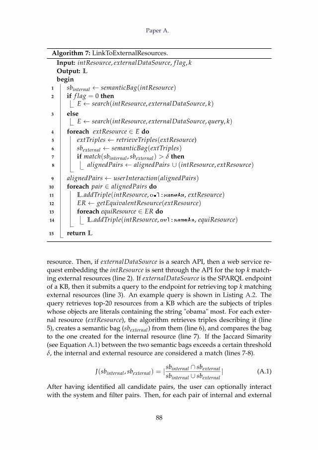
Paper A.
Algorithm 7: LinkToExternalResources.Input: intResource, externalDataSource, f lag, kOutput: L
begin1 sbinternal ← semanticBag(intResource)2 if f lag = 0 then
E← search(intResource, externalDataSource, k)3 else
E← search(intResource, externalDataSource, query, k)4 foreach extResource ∈ E do5 extTriples← retrieveTriples(extResource)6 sbexternal ← semanticBag(extTriples)7 if match(sbinternal , sbexternal) > δ then8 alignedPairs← alignedPairs ∪ (intResource, extResource)
9 alignedPairs← userInteraction(alignedPairs)10 foreach pair ∈ alignedPairs do11 L.addTriple(intResource, owl:sameAs, extResource)12 ER← getEquivalentResource(extResource)13 foreach equiResource ∈ ER do14 L.addTriple(intResource, owl:sameAs, equiResource)
15 return L
resource. Then, if externalDataSource is a search API, then a web service re-quest embedding the intResource is sent through the API for the top k match-ing external resources (line 2). If externalDataSource is the SPARQL endpointof a KB, then it submits a query to the endpoint for retrieving top k matchingexternal resources (line 3). An example query is shown in Listing A.2. Thequery retrieves top-20 resources from a KB which are the subjects of tripleswhose objects are literals containing the string "obama" most. For each exter-nal resource (extResource), the algorithm retrieves triples describing it (line5), creates a semantic bag (sbexternal) from them (line 6), and compares the bagto the one created for the internal resource (line 7). If the Jaccard Simarity(see Equation A.1) between the two semantic bags exceeds a certain thresholdδ, the internal and external resource are considered a match (lines 7-8).
J(sbinternal , sbexternal) = |sbinternal ∩ sbexternalsbinternal ∪ sbexternal
| (A.1)
After having identified all candidate pairs, the user can optionally interactwith the system and filter pairs. Then, for each pair of internal and external
88
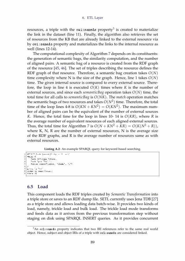
6. ETL Layer
resources, a triple with the owl:sameAs property3 is created to materializethe link in the dataset (line 11). Finally, the algorithm also retrieves the setof resources from the KB that are already linked to the external resource viaby owl:sameAs property and materializes the links to the internal resource aswell (lines 12-14).
The computational complexity of Algorithm 7 depends on its constituents:the generation of semantic bags, the similarity computation, and the numberof aligned pairs. A semantic bag of a resource is created from the RDF graphof the resource [45, 46]. The set of triples describing the resource defines theRDF graph of that resource. Therefore, a semantic bag creation takes O(N)time complexity where N is the size of the graph. Hence, line 1 takes O(N)time. The given internal source is compared to every external source. There-fore, the loop in line 4 is executed O(K) times where K is the number ofexternal sources, and since each semanticBag operation takes O(N) time, thetotal time for all calls to semanticBag is O(NK). The match operation matchesthe semantic bags of two resources and takes O(N2) time. Therefore, the totaltime of the loop lines 4-8 is O(KN + KN2) = O(KN2). The maximum num-ber of aligned pairs can be the equivalent of the number of external sourcesK. Hence, the total time for the loop in lines 10- 14 is O(KR), where R isthe average number of equivalent resources of each aligned external sources.Thus, the total time for Algorithm 7 is O(N + KN2 + KR) = O(K(N2 + R)),where K, N, R are the number of external resources, N is the average sizeof the RDF graphs, and R is the average number of resources same as withexternal resources.
Listing A.2: An example SPARQL query for keyword based searching.
1 SELECT ?sub (count(?sub) as ?count)
2 WHERE {
3 ?sub rdf:type ?class.
4 ?sub ?pro ?label.
5 Filter regex(?label , "obama", "i")
6 }
7 group by ?sub
8 order by desc(?count)
9 limit 20
6.5 Load
This component loads the RDF triples created by Semantic Transformation intoa triple store or saves to an RDF dump file. SETL currently uses Jena TDB [27]as a triple store and allows loading data batch-wise. It provides two kinds ofload, namely, trickle load and bulk load. The trickle load mode transformsand feeds data as it arrives from the previous transformation step withoutstaging on disk using SPARQL INSERT queries. As it provides concurrent
3An owl:sameAs property indicates that two IRI references refer to the same real worldobject. Hence, subject and object IRIs of a triple with owl:sameAs are considered linked.
89
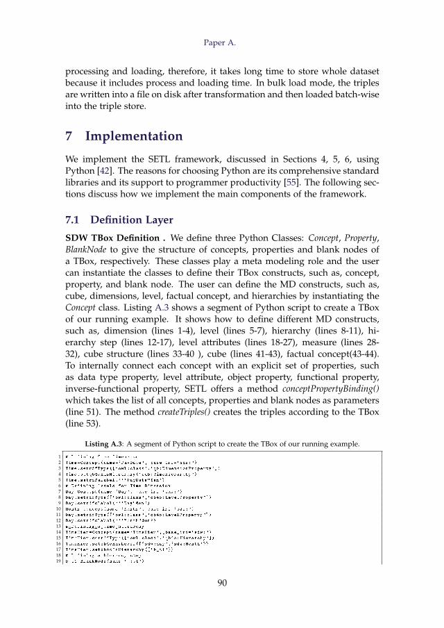
Paper A.
processing and loading, therefore, it takes long time to store whole datasetbecause it includes process and loading time. In bulk load mode, the triplesare written into a file on disk after transformation and then loaded batch-wiseinto the triple store.
7 Implementation
We implement the SETL framework, discussed in Sections 4, 5, 6, usingPython [42]. The reasons for choosing Python are its comprehensive standardlibraries and its support to programmer productivity [55]. The following sec-tions discuss how we implement the main components of the framework.
7.1 Definition Layer
SDW TBox Definition . We define three Python Classes: Concept, Property,BlankNode to give the structure of concepts, properties and blank nodes ofa TBox, respectively. These classes play a meta modeling role and the usercan instantiate the classes to define their TBox constructs, such as, concept,property, and blank node. The user can define the MD constructs, such as,cube, dimensions, level, factual concept, and hierarchies by instantiating theConcept class. Listing A.3 shows a segment of Python script to create a TBoxof our running example. It shows how to define different MD constructs,such as, dimension (lines 1-4), level (lines 5-7), hierarchy (lines 8-11), hi-erarchy step (lines 12-17), level attributes (lines 18-27), measure (lines 28-32), cube structure (lines 33-40 ), cube (lines 41-43), factual concept(43-44).To internally connect each concept with an explicit set of properties, suchas data type property, level attribute, object property, functional property,inverse-functional property, SETL offers a method conceptPropertyBinding()which takes the list of all concepts, properties and blank nodes as parameters(line 51). The method createTriples() creates the triples according to the TBox(line 53).
Listing A.3: A segment of Python script to create the TBox of our running example.
1 # Defining Time Dimension
2 Time=Concept(name=`PayDate ',_base_iri=`sdw:')
3 Time.setrdfType ([`owl:class',`qb:DimensionProperty '])
4 Time.setqb4oHasHierarchy(`sub:TimeHierarchy ')
5 Time.setrdfsLabel(```PayDate"@en')
6 # Defining levels for Time Dimension
7 Day=Concept(name=`Day',_base_iri=`sdw:')
8 Day.setrdfType ([`owl:class ',`qb4o:LevelProperty '])
9 Day.setrdfsLabel(```Day"@en ')
10 Month=Concept(name=`Month ',_base_iri=`sdw:')
11 Day.setrdfType ([`owl:class ',`qb4o:LevelProperty '])
12 Day.setrdfsLabel(```Month"@en')
13 # Defining a time hierarchy
14 TimeHier=Concept(name=`TimeHier ',_base_iri=`sdw:')
15 TimeHier.setrdfType ([`owl:class ',`qb4o:Hierarchy '])
16 TimeHier.setqb4oHasLevel ([`sdw:day',`sdw:Month'}}
17 TimeHier.setqb4oInHierarchy ([`b_t1'}}
18 # Defining a hierarcy step
19 b_t1=BlankNode(name=`_:t1')
90
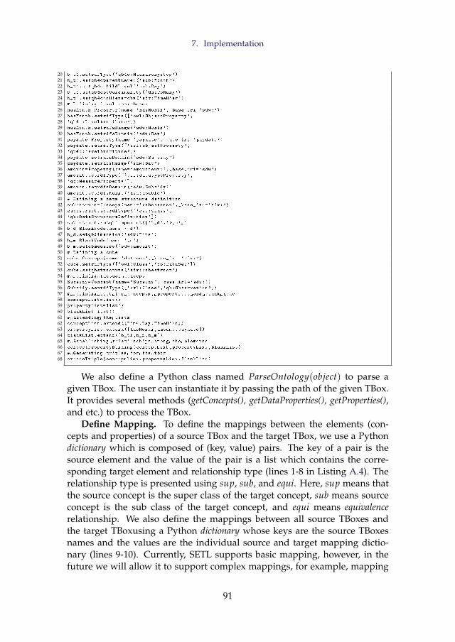
7. Implementation
20 b_t1.setrdfType(`qb4o:HierarchyStep ')
21 b_t1.setqb4oparentLevel(`sub:Month ')
22 b_t1.setqb4ochildLevel(`sub:Day')
23 b_t1.setqb4opcCardinality(`OneToMany ')
24 b_t1.setqb4oinHierarchy(`sdw:TimeHier ')
25 # Defining level attributes
26 hasMonth=Property(name=`hasMonth ',_base_iri=`sdw:')
27 hasMonth.setrdfType ([`owl:ObjectProperty ',
28 `qb4o:LevelAttribute '])
29 hasMonth.setrdfsRange(`sdw:Month ')
30 hasMonth.setrdfsDomain(`sdw:Day')
31 paydate=Property(name=`paydate ',_base_iri=`paydate ')
32 paydate.setrdfType ([`owl:objectProperty ',
33 `qb4o:levelAttribute '])
34 paydate.setrdfsDomain(`sdw:Subsidy ')
35 paydate.setrdfsRange(`sdw:Day')
36 amount=Property(name=`amounteuro ',_base_iri=`sdw')
37 amount.setrdfType ([`owl:datatypeProperty ',
38 `qb:MeasureProperty '])
39 amount.setrdfsDomain(`sdw:Subsidy ')
40 amount.setrdfsRange(`xsd:double ')
41 # Defining a data structure definition
42 cubestruct=Concept(name=`cubestruct ',_base_iri=`sdw:')
43 cubestruct.setrdfType ([`owl:Class',
44 `qb:DataStructureDefinition '])
45 cubestruct.setqbComponent ([`b_d',`b_m'])
46 b_d=BlankNode(name=`_d')
47 b_d.setqbdimension(`sdw:Time')
48 b_m=BlankNode(name=`_m')
49 b_m.setqbmeasure(`sdw:amount ')
50 # Defining a cube
51 cube=Concept(name=`dataset ',_base_iri=`sdw:')
52 cube.setrdfType ([`owl:Class',`qb:DataSet '])
53 cube.setqbstructure(`sdw:cubestruct ')
54 # Defining factual concept
55 Subsidy=Concept(name=`Subsidy ',_base_iri=`sdw:')
56 Subsidy.setrdfType ([`owl:Class',`qb:Observation '})
57 # Defining list for concepts , properties , and blank node
58 conceptList=list()
59 propertylist=list()
60 blankList=list()
61 # Extending the lists
62 conceptList.extend ([Time ,Day ,TimeHier ])
63 propertyList.extend ([hasMonth ,amount ,paydate ])
64 blankList.extend ([b_t1 ,b_d ,b_m])
65 # Establishing relationships among the elements
66 conceptPropertyBinding(conceptList ,propertyList ,blankList)
67 # Generating triples for the tbox
68 createTriple(conceptlist ,propertyList ,BlankList)
We also define a Python class named ParseOntology(object) to parse agiven TBox. The user can instantiate it by passing the path of the given TBox.It provides several methods (getConcepts(), getDataProperties(), getProperties(),and etc.) to process the TBox.
Define Mapping. To define the mappings between the elements (con-cepts and properties) of a source TBox and the target TBox, we use a Pythondictionary which is composed of (key, value) pairs. The key of a pair is thesource element and the value of the pair is a list which contains the corre-sponding target element and relationship type (lines 1-8 in Listing A.4). Therelationship type is presented using sup, sub, and equi. Here, sup means thatthe source concept is the super class of the target concept, sub means sourceconcept is the sub class of the target concept, and equi means equivalencerelationship. We also define the mappings between all source TBoxes andthe target TBoxusing a Python dictionary whose keys are the source TBoxesnames and the values are the individual source and target mapping dictio-nary (lines 9-10). Currently, SETL supports basic mapping, however, in thefuture we will allow it to support complex mappings, for example, mapping
91
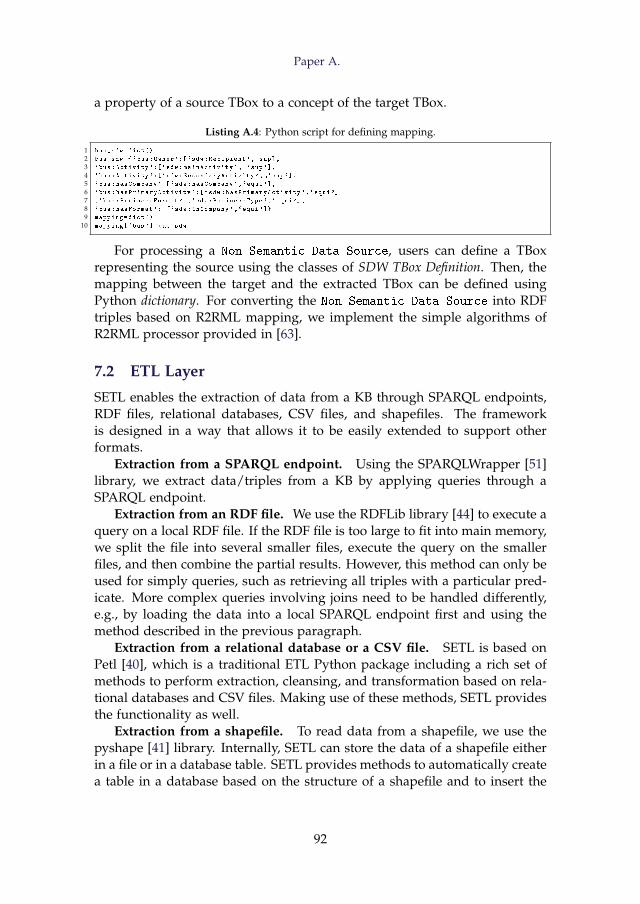
Paper A.
a property of a source TBox to a concept of the target TBox.
Listing A.4: Python script for defining mapping.
1 bus_sdw=dict()
2 bus_sdw={`bus:Owner':[`sdw:Recipient ', sup],
3 `bus:Activity ':[`sdw:mainActivity ', `sup'],
4 `bus:Activity ':[`sdw:SecondaryActivity ', `sup'],
5 `bus:hasCompany ':[`sdw:hasCompany ',`equi'],
6 `bus:hasPrimaryActivity ':[`sdw:hasPrimaryActivity ',`equi']
7 ,`bus:BusinessFormat ':[`sdw:BusinessType ',`equi'],
8 `bus:hasFormat ': [`sdw:inCompany ',`equi']}
9 mapping=dict()
10 mapping[`bus']= bus_sdw
For processing a Non Semantic Data Source, users can define a TBoxrepresenting the source using the classes of SDW TBox Definition. Then, themapping between the target and the extracted TBox can be defined usingPython dictionary. For converting the Non Semantic Data Source into RDFtriples based on R2RML mapping, we implement the simple algorithms ofR2RML processor provided in [63].
7.2 ETL Layer
SETL enables the extraction of data from a KB through SPARQL endpoints,RDF files, relational databases, CSV files, and shapefiles. The frameworkis designed in a way that allows it to be easily extended to support otherformats.
Extraction from a SPARQL endpoint. Using the SPARQLWrapper [51]library, we extract data/triples from a KB by applying queries through aSPARQL endpoint.
Extraction from an RDF file. We use the RDFLib library [44] to execute aquery on a local RDF file. If the RDF file is too large to fit into main memory,we split the file into several smaller files, execute the query on the smallerfiles, and then combine the partial results. However, this method can only beused for simply queries, such as retrieving all triples with a particular pred-icate. More complex queries involving joins need to be handled differently,e.g., by loading the data into a local SPARQL endpoint first and using themethod described in the previous paragraph.
Extraction from a relational database or a CSV file. SETL is based onPetl [40], which is a traditional ETL Python package including a rich set ofmethods to perform extraction, cleansing, and transformation based on rela-tional databases and CSV files. Making use of these methods, SETL providesthe functionality as well.
Extraction from a shapefile. To read data from a shapefile, we use thepyshape [41] library. Internally, SETL can store the data of a shapefile eitherin a file or in a database table. SETL provides methods to automatically createa table in a database based on the structure of a shapefile and to insert the
92
7. Implementation
data from the shapefile into the created table. It also provides a method tostore the attribute information of a shapefile in CSV format.
Figure A.1 shows that there is no direct connection between Field andOrganicField, neither between Field and FieldBlock. In the target TBox (Fig-ure A.3), however, we have defined connections, e.g., agri:Field and agri:Or
ganicField are connected through the owl:sameAs property and agri:Field
Block and agri:Field are connected via the agri:contains property. Theseconnections are computed based on a spatial join that SETL computes duringthe extraction process for pairs of shapefiles. We use the ArcPy [5] library toperform the spatial join analysis.
Transformation. To perform the operations related to Traditional Trans-formation, described in the 2nd paragraph of Section 6, we again use thePetl [40] library. For creating RDF triples according to the target TBox basedon the data output from the Traditional Transformation component, we de-velop a Python method, named createTriples(table, resourceKey, onto, mapping,provGraph, filepath) that implements Algorithm 6, where the parameters main-tain the same meanings as Algorithm 6. Additionally, it requires a parameterf ilepath, the location of the file, to store the generated RDF triples.
External Linking. We develop a method named link(intResource, extSource,flag, k) that implements Algorithm 7. We use Python built-in requests libraryto retrieve the top-k related resources of inResource through DBpedia LoopupAPI in JSON format. Sometimes the queries submitted to a SPARQL endpointresult in timeout error. For this reason, we download the RDF dump files ofthe selected KB and store them to a triple store locally for accessing it throughlocal SPARQL endpoint.
Load. Bulk load stores the RDF triples from a file (created by createTriple() method) to the triple store. To support bulk load, SETL offers two methods:bulkTDBLoader (tdblocation, filePath, batchsize) and bulkSPARQLInsert(tdblocation, filePath, batchsize, database). The BulkTDBLoader is used to load datafrom a file on disk into a triple store using the jena TDBLoader command.The parameter tdblocation denotes the location of a TDB database, the filePathis the path to the triple file, and batchsize is the number of triples to be fedinto the store at a time. The BulkSPARQLInsert is similar to BulkTDBLoader butdefines SPARQL INSERT statements to load triples instead of using the jenaTDBLoader command. It additionally requires the name of the database asparameter. Unlike bulk load, which loads the triples from a file, trickle loadconverts the cleansed and transformed data into triples and subsequentlyloads them into a triple store holding the triples in main memory. Thetrickleload(table, resourceKey, onto, mapping, provGraph, tdblocation, batchsize)method has same parameters like createTriple() method. In addition, it takestdblocation and batchsize as input parameters to directly load the triples intothe triple store.
93
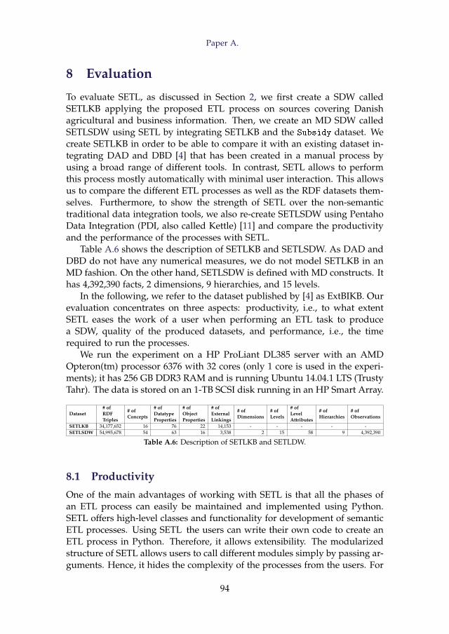
Paper A.
8 Evaluation
To evaluate SETL, as discussed in Section 2, we first create a SDW calledSETLKB applying the proposed ETL process on sources covering Danishagricultural and business information. Then, we create an MD SDW calledSETLSDW using SETL by integrating SETLKB and the Subsidy dataset. Wecreate SETLKB in order to be able to compare it with an existing dataset in-tegrating DAD and DBD [4] that has been created in a manual process byusing a broad range of different tools. In contrast, SETL allows to performthis process mostly automatically with minimal user interaction. This allowsus to compare the different ETL processes as well as the RDF datasets them-selves. Furthermore, to show the strength of SETL over the non-semantictraditional data integration tools, we also re-create SETLSDW using PentahoData Integration (PDI, also called Kettle) [11] and compare the productivityand the performance of the processes with SETL.
Table A.6 shows the description of SETLKB and SETLSDW. As DAD andDBD do not have any numerical measures, we do not model SETLKB in anMD fashion. On the other hand, SETLSDW is defined with MD constructs. Ithas 4,392,390 facts, 2 dimensions, 9 hierarchies, and 15 levels.
In the following, we refer to the dataset published by [4] as ExtBIKB. Ourevaluation concentrates on three aspects: productivity, i.e., to what extentSETL eases the work of a user when performing an ETL task to producea SDW, quality of the produced datasets, and performance, i.e., the timerequired to run the processes.
We run the experiment on a HP ProLiant DL385 server with an AMDOpteron(tm) processor 6376 with 32 cores (only 1 core is used in the experi-ments); it has 256 GB DDR3 RAM and is running Ubuntu 14.04.1 LTS (TrustyTahr). The data is stored on an 1-TB SCSI disk running in an HP Smart Array.
Dataset# ofRDFTriples
# ofConcepts
# ofDatatypeProperties
# ofObjectProperties
# ofExternalLinkings
# ofDimensions
# ofLevels
# ofLevelAttributes
# ofHierarchies
# ofObservations
SETLKB 34,177,652 16 76 22 14,153 - - - - -SETLSDW 54,995,678 54 63 16 3,538 2 15 58 9 4,392,390
Table A.6: Description of SETLKB and SETLDW.
8.1 Productivity
One of the main advantages of working with SETL is that all the phases ofan ETL process can easily be maintained and implemented using Python.SETL offers high-level classes and functionality for development of semanticETL processes. Using SETL the users can write their own code to create anETL process in Python. Therefore, it allows extensibility. The modularizedstructure of SETL allows users to call different modules simply by passing ar-guments. Hence, it hides the complexity of the processes from the users. For
94
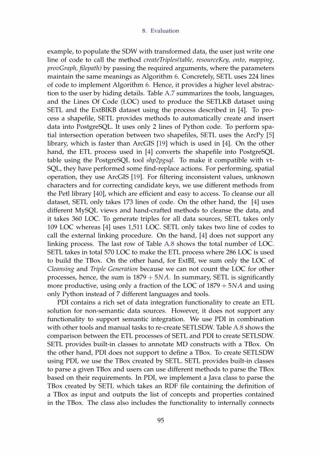
8. Evaluation
example, to populate the SDW with transformed data, the user just write oneline of code to call the method createTriples(table, resourceKey, onto, mapping,provGraph, filepath) by passing the required arguments, where the parametersmaintain the same meanings as Algorithm 6. Concretely, SETL uses 224 linesof code to implement Algorithm 6. Hence, it provides a higher level abstrac-tion to the user by hiding details. Table A.7 summarizes the tools, languages,and the Lines Of Code (LOC) used to produce the SETLKB dataset usingSETL and the ExtBIKB dataset using the process described in [4]. To pro-cess a shapefile, SETL provides methods to automatically create and insertdata into PostgreSQL. It uses only 2 lines of Python code. To perform spa-tial intersection operation between two shapefiles, SETL uses the ArcPy [5]library, which is faster than ArcGIS [19] which is used in [4]. On the otherhand, the ETL process used in [4] converts the shapefile into PostgreSQLtable using the PostgreSQL tool shp2pgsql. To make it compatible with vt-SQL, they have performed some find-replace actions. For performing, spatialoperation, they use ArcGIS [19]. For filtering inconsistent values, unknowncharacters and for correcting candidate keys, we use different methods fromthe Petl library [40], which are efficient and easy to access. To cleanse our alldataset, SETL only takes 173 lines of code. On the other hand, the [4] usesdifferent MySQL views and hand-crafted methods to cleanse the data, andit takes 360 LOC. To generate triples for all data sources, SETL takes only109 LOC whereas [4] uses 1,511 LOC. SETL only takes two line of codes tocall the external linking procedure. On the hand, [4] does not support anylinking process. The last row of Table A.8 shows the total number of LOC.SETL takes in total 570 LOC to make the ETL process where 286 LOC is usedto build the TBox. On the other hand, for ExtBI, we sum only the LOC ofCleansing and Triple Generation because we can not count the LOC for otherprocesses, hence, the sum is 1879 + 5NA. In summary, SETL is significantlymore productive, using only a fraction of the LOC of 1879 + 5NA and usingonly Python instead of 7 different languages and tools.
PDI contains a rich set of data integration functionality to create an ETLsolution for non-semantic data sources. However, it does not support anyfunctionality to support semantic integration. We use PDI in combinationwith other tools and manual tasks to re-create SETLSDW. Table A.8 shows thecomparison between the ETL processes of SETL and PDI to create SETLSDW.SETL provides built-in classes to annotate MD constructs with a TBox. Onthe other hand, PDI does not support to define a TBox. To create SETLSDWusing PDI, we use the TBox created by SETL. SETL provides built-in classesto parse a given TBox and users can use different methods to parse the TBoxbased on their requirements. In PDI, we implement a Java class to parse theTBox created by SETL which takes an RDF file containing the definition ofa TBox as input and outputs the list of concepts and properties containedin the TBox. The class also includes the functionality to internally connects
95
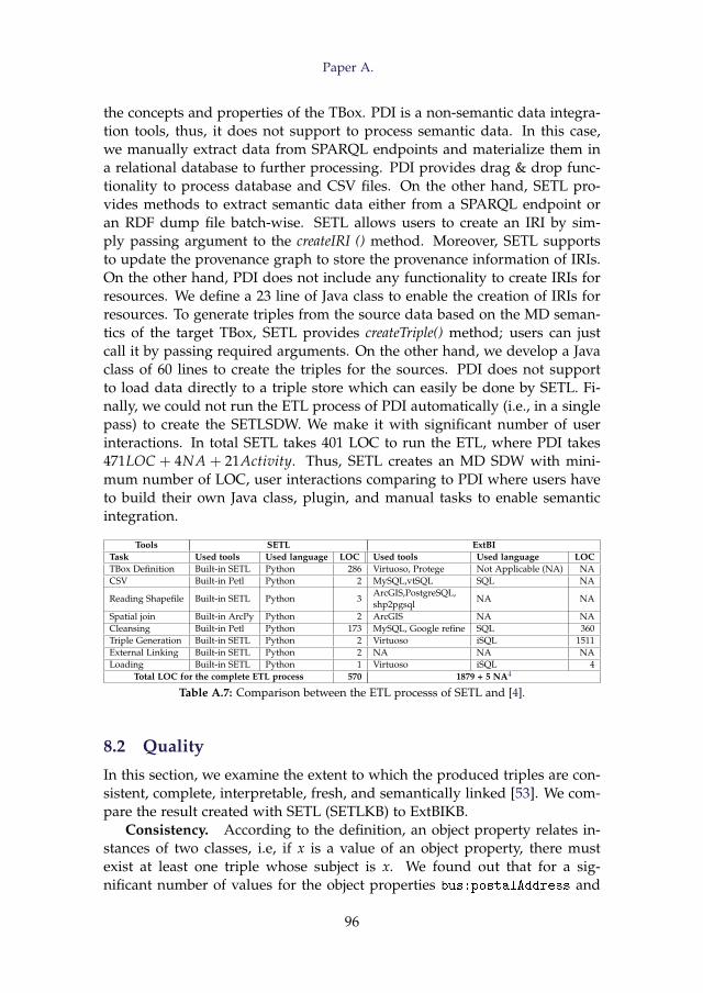
Paper A.
the concepts and properties of the TBox. PDI is a non-semantic data integra-tion tools, thus, it does not support to process semantic data. In this case,we manually extract data from SPARQL endpoints and materialize them ina relational database to further processing. PDI provides drag & drop func-tionality to process database and CSV files. On the other hand, SETL pro-vides methods to extract semantic data either from a SPARQL endpoint oran RDF dump file batch-wise. SETL allows users to create an IRI by sim-ply passing argument to the createIRI () method. Moreover, SETL supportsto update the provenance graph to store the provenance information of IRIs.On the other hand, PDI does not include any functionality to create IRIs forresources. We define a 23 line of Java class to enable the creation of IRIs forresources. To generate triples from the source data based on the MD seman-tics of the target TBox, SETL provides createTriple() method; users can justcall it by passing required arguments. On the other hand, we develop a Javaclass of 60 lines to create the triples for the sources. PDI does not supportto load data directly to a triple store which can easily be done by SETL. Fi-nally, we could not run the ETL process of PDI automatically (i.e., in a singlepass) to create the SETLSDW. We make it with significant number of userinteractions. In total SETL takes 401 LOC to run the ETL, where PDI takes471LOC + 4NA + 21Activity. Thus, SETL creates an MD SDW with mini-mum number of LOC, user interactions comparing to PDI where users haveto build their own Java class, plugin, and manual tasks to enable semanticintegration.
Tools SETL ExtBITask Used tools Used language LOC Used tools Used language LOCTBox Definition Built-in SETL Python 286 Virtuoso, Protege Not Applicable (NA) NACSV Built-in Petl Python 2 MySQL,vtSQL SQL NA
Reading Shapefile Built-in SETL Python 3ArcGIS,PostgreSQL,shp2pgsql
NA NA
Spatial join Built-in ArcPy Python 2 ArcGIS NA NACleansing Built-in Petl Python 173 MySQL, Google refine SQL 360Triple Generation Built-in SETL Python 2 Virtuoso iSQL 1511External Linking Built-in SETL Python 2 NA NA NALoading Built-in SETL Python 1 Virtuoso iSQL 4
Total LOC for the complete ETL process 570 1879 + 5 NA4
Table A.7: Comparison between the ETL processs of SETL and [4].
8.2 Quality
In this section, we examine the extent to which the produced triples are con-sistent, complete, interpretable, fresh, and semantically linked [53]. We com-pare the result created with SETL (SETLKB) to ExtBIKB.
Consistency. According to the definition, an object property relates in-stances of two classes, i.e, if x is a value of an object property, there mustexist at least one triple whose subject is x. We found out that for a sig-nificant number of values for the object properties bus:postalAddress and
96
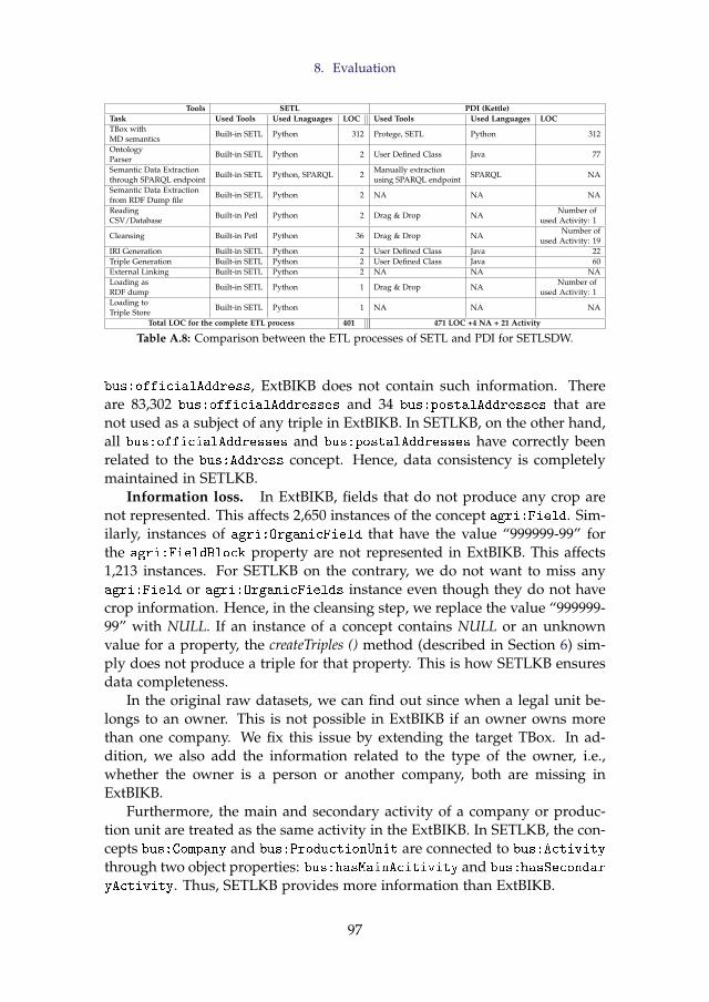
8. Evaluation
Tools SETL PDI (Kettle)Task Used Tools Used Lnaguages LOC Used Tools Used Languages LOCTBox withMD semantics
Built-in SETL Python 312 Protege, SETL Python 312
OntologyParser
Built-in SETL Python 2 User Defined Class Java 77
Semantic Data Extractionthrough SPARQL endpoint
Built-in SETL Python, SPARQL 2Manually extractionusing SPARQL endpoint
SPARQL NA
Semantic Data Extractionfrom RDF Dump file
Built-in SETL Python 2 NA NA NA
ReadingCSV/Database
Built-in Petl Python 2 Drag & Drop NANumber of
used Activity: 1
Cleansing Built-in Petl Python 36 Drag & Drop NANumber of
used Activity: 19IRI Generation Built-in SETL Python 2 User Defined Class Java 22Triple Generation Built-in SETL Python 2 User Defined Class Java 60External Linking Built-in SETL Python 2 NA NA NALoading asRDF dump
Built-in SETL Python 1 Drag & Drop NANumber of
used Activity: 1Loading toTriple Store
Built-in SETL Python 1 NA NA NA
Total LOC for the complete ETL process 401 471 LOC +4 NA + 21 Activity
Table A.8: Comparison between the ETL processes of SETL and PDI for SETLSDW.
bus:officialAddress, ExtBIKB does not contain such information. Thereare 83,302 bus:officialAddresses and 34 bus:postalAddresses that arenot used as a subject of any triple in ExtBIKB. In SETLKB, on the other hand,all bus:officialAddresses and bus:postalAddresses have correctly beenrelated to the bus:Address concept. Hence, data consistency is completelymaintained in SETLKB.
Information loss. In ExtBIKB, fields that do not produce any crop arenot represented. This affects 2,650 instances of the concept agri:Field. Sim-ilarly, instances of agri:OrganicField that have the value “999999-99” forthe agri:FieldBlock property are not represented in ExtBIKB. This affects1,213 instances. For SETLKB on the contrary, we do not want to miss anyagri:Field or agri:OrganicFields instance even though they do not havecrop information. Hence, in the cleansing step, we replace the value “999999-99” with NULL. If an instance of a concept contains NULL or an unknownvalue for a property, the createTriples () method (described in Section 6) sim-ply does not produce a triple for that property. This is how SETLKB ensuresdata completeness.
In the original raw datasets, we can find out since when a legal unit be-longs to an owner. This is not possible in ExtBIKB if an owner owns morethan one company. We fix this issue by extending the target TBox. In ad-dition, we also add the information related to the type of the owner, i.e.,whether the owner is a person or another company, both are missing inExtBIKB.
Furthermore, the main and secondary activity of a company or produc-tion unit are treated as the same activity in the ExtBIKB. In SETLKB, the con-cepts bus:Company and bus:ProductionUnit are connected to bus:Activity
through two object properties: bus:hasMainAcitivity and bus:hasSecondar
yActivity. Thus, SETLKB provides more information than ExtBIKB.
97
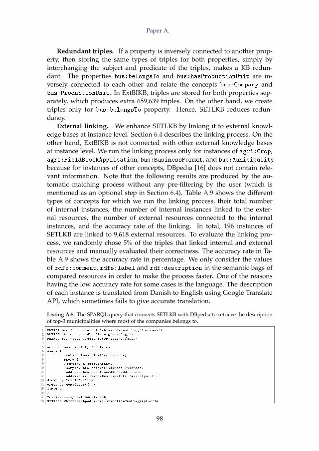
Paper A.
Redundant triples. If a property is inversely connected to another prop-erty, then storing the same types of triples for both properties, simply byinterchanging the subject and predicate of the triples, makes a KB redun-dant. The properties bus:belongsTo and bus:hasProductionUnit are in-versely connected to each other and relate the concepts bus:Company andbus:ProductionUnit. In ExtBIKB, triples are stored for both properties sep-arately, which produces extra 659,639 triples. On the other hand, we createtriples only for bus:belongsTo property. Hence, SETLKB reduces redun-dancy.
External linking. We enhance SETLKB by linking it to external knowl-edge bases at instance level. Section 6.4 describes the linking process. On theother hand, ExtBIKB is not connected with other external knowledge basesat instance level. We run the linking process only for instances of agri:Crop,agri:FieldBlockApplication, bus:BusinessFormat, and bus:Municipality
because for instances of other concepts, DBpedia [16] does not contain rele-vant information. Note that the following results are produced by the au-tomatic matching process without any pre-filtering by the user (which ismentioned as an optional step in Section 6.4). Table A.9 shows the differenttypes of concepts for which we run the linking process, their total numberof internal instances, the number of internal instances linked to the exter-nal resources, the number of external resources connected to the internalinstances, and the accuracy rate of the linking. In total, 196 instances ofSETLKB are linked to 9,618 external resources. To evaluate the linking pro-cess, we randomly chose 5% of the triples that linked internal and externalresources and manually evaluated their correctness. The accuracy rate in Ta-ble A.9 shows the accuracy rate in percentage. We only consider the valuesof rdfs:comment, rdfs:label and rdf:description in the semantic bags ofcompared resources in order to make the process faster. One of the reasonshaving the low accuracy rate for some cases is the language. The descriptionof each instance is translated from Danish to English using Google TranslateAPI, which sometimes fails to give accurate translation.
Listing A.5: The SPARQL query that connects SETLKB with DBpedia to retrieve the descriptionof top-3 municipalities where most of the companies belongs to.
1 PREFIX bus:<http :// extbi.lab.aau.dk/ontology/business/>
2 PREFIX dbo:<http :// dbpedia.org/ontology/>
3 PREFIX owl:<http ://www.w3.org /2002/07/ owl#>
45 select ?municipality ?abstract
6 where {
7 {select ?municipality count (*)
8 where {
9 ?company a bus:Company.
10 ?company bus:officialAddress ?address.
11 ?address bus:positionedAt ?addFeature.
12 ?addFeature bus:inMunicipality ?municipality .}
13 Group by ?municipality
14 order by desc(count (*))
15 limit 3
16 }
17 ?municipality owl:sameAs ?db.
18 SERVICE <http :// dbpedia.org/sparql?default -graph -uri=
98
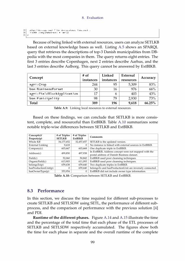
8. Evaluation
19 http :// dbpedia.org > { ?db dbo:abstract ?abstract .
20 FILTER (lang(? abstract) = 'en')}
21 }
Because of being linked with external resources, users can analyze SETLKBbased on external knowledge bases as well. Listing A.5 shows an SPARQLquery that retrieves the descriptions of top-3 Danish municipalities from DB-pedia with the most companies in them. The query returns eight entries. Thefirst 3 entries describe Copenhagen, next 2 entries describe Aarhus, and thelast 3 entries describe Aalborg. This query cannot be answered by ExtBIKB.
Concept# ofinstances
Linkedinstances
Externalresources
Accuracy
agri:Crop 244 95 5,309 83%bus:BusinessFormat 30 16 976 66%agri:FieldBlockApplication 17 6 403 43%bus:Municipality 98 79 2,930 73%Total 389 196 9,618 66.25%
Table A.9: Linking local resources to external resources.
Based on these findings, we can conclude that SETLKB is more consis-tent, complete, and resourceful than ExtBIKB. Table A.10 summarizes somenotable triple-wise differences between SETLKB and ExtBIKB.
Concept(c)/Property(p)
# of TriplesSETLKB
# of TriplesExtBIKB
Comments
Whole KB 34,177,652 32,457,657 SETLKB is the updated version.External Linking 9,618 0 No instance is linked with external sources in ExtBIKB.Company(c) 603,667 603,668 One duplicate triple in ExtBIKB.
Address(c) 499,850 497,938In ExtBIKB, Address concept were not mapped with thepostal address of Danish Business dataset.
Field(c) 52,060 50,842 ExtBIKB used poor cleansing techniques.OrganicField(c) 613,903 611,093 ExtBIKB used poor cleansing techniques.belongsTo(p) 659,638 659,640 Two duplicate triples in ExtBIKB.hasProductionUnit(p) 0 659,640 belongsTo and hasProductionUnit are inversely connected.hasOwnerType(p) 353,954 0 ExtBIKB did not include owner type information.
Table A.10: Comparison between SETLKB and ExtBIKB.
8.3 Performance
In this section, we discuss the time required for different sub-processes tocreate SETLKB and SETLSDW using SETL, the performance of different sub-process, and the comparison of performance with the previous solution [4]and PDI.
Runtime of the different phases. Figure A.14 and A.15 illustrate the timeand the percentage of the total time that each phase of the ETL processes ofSETLKB and SETLSDW respectively accumulated. The figures show boththe time for each phase in separate and the overall runtime of the complete
99
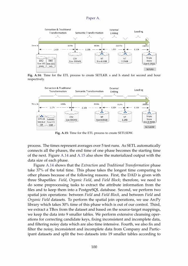
Paper A.
Fig. A.14: Time for the ETL process to create SETLKB. s and h stand for second and hourrespectively.
Fig. A.15: Time for the ETL process to create SETLSDW.
process. The times represent averages over 5 test runs. As SETL automaticallyconnects all the phases, the end time of one phase becomes the starting timeof the next. Figure A.14 and A.15 also show the materialized output with thedata size of each phase.
Figure A.14 shows that the Extraction and Traditional Transformation phasetake 37% of the total time. This phase takes the longest time comparing toother phases because of the following reasons. First, the DAD is given withthree Shapefiles: Field, Organic Field, and Field Block; therefore, we need todo some preprocessing tasks to extract the attribute information from thefiles and to keep them into a PostgreSQL database. Second, we perform twospatial join operations: between Field and Field Block, and between Field andOrganic Field datasets. To perform the spatial join operations, we use ArcPylibrary which takes 30% time of this phase which is out of our control. Third,we extract a TBox from the dataset and based on the source-target mappings,we keep the data into 9 smaller tables. We perform extensive cleansing oper-ations for correcting candidate keys, fixing inconsistent and incomplete data,and filtering noisy data which are also time intensive. Fourth, we also fix andfilter the noisy, inconsistent and incomplete data from Company and Partic-ipant datasets and split the two datasets into 19 smaller tables according to
100
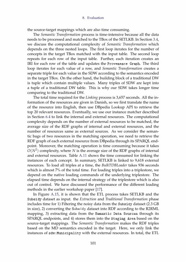
8. Evaluation
the source-target mappings which are also time consuming.The Semantic Transformation process is time-intensive because all the data
needs to be processed and matched to the TBox of the SETLKB. In Section 3.4,we discuss the computational complexity of Semantic Transformation whichdepends on the three nested loops. The first loop iterates for the number ofconcepts in the target TBox matched with the input table. The second looprepeats for each row of the input table. Further, each iteration creates anIRI for each row of the table and updates the Provenance Graph. The thirdloop iterates for each value of a row, and Semantic Transformation creates aseparate triple for each value in the SDW according to the semantics encodedin the target TBox. On the other hand, the building block of a traditional DWis tuple which contain multiple values. Many triples of SDW are kept intoa tuple of a traditional DW table. This is why our SDW takes longer timecomparing to the traditional DW.
The total time required for the Linking process is 3,657 seconds. All the in-formation of the resources are given in Danish, so we first translate the nameof the resource into English, then use DBpedia Lookup API to retrieve thetop 20 relevant resources. Eventually, we use our instance matcher describedin Section 6.4 to link the internal and external resources. The computationalcomplexity depends on the number of external resources to be matched, theaverage size of the RDF graphs of internal and external resources, and thenumber of resources same as external sources. As we consider the seman-tic bags of two resources in the matching operation, we need to retrieve theRDF graph of each external resource from DBpedia through its SPARQL end-point. Moreover, the matching operation is time consuming because it takesO(N2) complexity, where N is the average size of the RDF graphs of internaland external resources. Table A.11 shows the time consumed for linking theinstances of each concept. In summary, SETLKB is linked to 9,618 externalresources. To load all triples at a time, the BulkTDBLoader takes 936 secondswhich is almost 7% of the total time. For loading triples into a triplestore, wedepend on the native loading commands of the underlying triplestore. Theelapsed time depends on the internal strategy of the triplestore which is alsoout of control. We have discussed the performance of the different loadingmethods in the earlier workshop paper [17].
In Figure A.15, it is shown that the ETL process takes SETLKB and theSubsidy dataset as input. the Extraction and Traditional Transformation phaseincludes time for 1) Filtering the noisy data from the Subsidy dataset (2.3 GBin size), 2) converting the Subsidy dataset into RDF according to the R2RMLmapping, 3) extracting data from the Semantic Data Sources through itsSPARQL endpoints, and 4) stores them into the Staging Area based on thesource-target mappings. The Semantic Transformation makes the RDF triplesbased on the MD semantics encoded in the target. Here, we only link theinstances of sdw:Municipality with the external resources. In total, the ETL
101
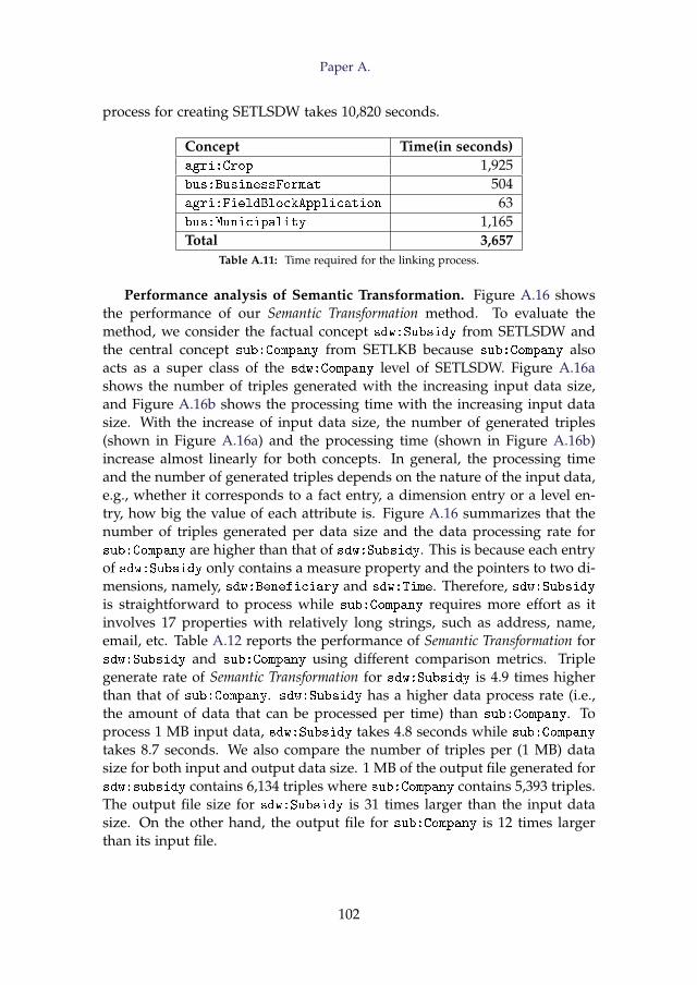
Paper A.
process for creating SETLSDW takes 10,820 seconds.
Concept Time(in seconds)agri:Crop 1,925bus:BusinessFormat 504agri:FieldBlockApplication 63bus:Municipality 1,165Total 3,657
Table A.11: Time required for the linking process.
Performance analysis of Semantic Transformation. Figure A.16 showsthe performance of our Semantic Transformation method. To evaluate themethod, we consider the factual concept sdw:Subsidy from SETLSDW andthe central concept sub:Company from SETLKB because sub:Company alsoacts as a super class of the sdw:Company level of SETLSDW. Figure A.16ashows the number of triples generated with the increasing input data size,and Figure A.16b shows the processing time with the increasing input datasize. With the increase of input data size, the number of generated triples(shown in Figure A.16a) and the processing time (shown in Figure A.16b)increase almost linearly for both concepts. In general, the processing timeand the number of generated triples depends on the nature of the input data,e.g., whether it corresponds to a fact entry, a dimension entry or a level en-try, how big the value of each attribute is. Figure A.16 summarizes that thenumber of triples generated per data size and the data processing rate forsub:Company are higher than that of sdw:Subsidy. This is because each entryof sdw:Subsidy only contains a measure property and the pointers to two di-mensions, namely, sdw:Beneficiary and sdw:Time. Therefore, sdw:Subsidyis straightforward to process while sub:Company requires more effort as itinvolves 17 properties with relatively long strings, such as address, name,email, etc. Table A.12 reports the performance of Semantic Transformation forsdw:Subsidy and sub:Company using different comparison metrics. Triplegenerate rate of Semantic Transformation for sdw:Subsidy is 4.9 times higherthan that of sub:Company. sdw:Subsidy has a higher data process rate (i.e.,the amount of data that can be processed per time) than sub:Company. Toprocess 1 MB input data, sdw:Subsidy takes 4.8 seconds while sub:Company
takes 8.7 seconds. We also compare the number of triples per (1 MB) datasize for both input and output data size. 1 MB of the output file generated forsdw:subsidy contains 6,134 triples where sub:Company contains 5,393 triples.The output file size for sdw:Subsidy is 31 times larger than the input datasize. On the other hand, the output file for sub:Company is 12 times largerthan its input file.
102
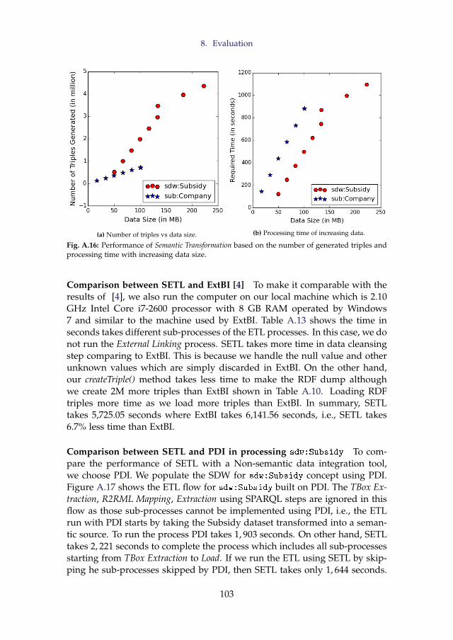
8. Evaluation
(a) Number of triples vs data size. (b) Processing time of increasing data.
Fig. A.16: Performance of Semantic Transformation based on the number of generated triples andprocessing time with increasing data size.
Comparison between SETL and ExtBI [4] To make it comparable with theresults of [4], we also run the computer on our local machine which is 2.10GHz Intel Core i7-2600 processor with 8 GB RAM operated by Windows7 and similar to the machine used by ExtBI. Table A.13 shows the time inseconds takes different sub-processes of the ETL processes. In this case, we donot run the External Linking process. SETL takes more time in data cleansingstep comparing to ExtBI. This is because we handle the null value and otherunknown values which are simply discarded in ExtBI. On the other hand,our createTriple() method takes less time to make the RDF dump althoughwe create 2M more triples than ExtBI shown in Table A.10. Loading RDFtriples more time as we load more triples than ExtBI. In summary, SETLtakes 5,725.05 seconds where ExtBI takes 6,141.56 seconds, i.e., SETL takes6.7% less time than ExtBI.
Comparison between SETL and PDI in processing sdw:Subsidy To com-pare the performance of SETL with a Non-semantic data integration tool,we choose PDI. We populate the SDW for sdw:Subsidy concept using PDI.Figure A.17 shows the ETL flow for sdw:Subsidy built on PDI. The TBox Ex-traction, R2RML Mapping, Extraction using SPARQL steps are ignored in thisflow as those sub-processes cannot be implemented using PDI, i.e., the ETLrun with PDI starts by taking the Subsidy dataset transformed into a seman-tic source. To run the process PDI takes 1, 903 seconds. On other hand, SETLtakes 2, 221 seconds to complete the process which includes all sub-processesstarting from TBox Extraction to Load. If we run the ETL using SETL by skip-ping he sub-processes skipped by PDI, then SETL takes only 1, 644 seconds.
103
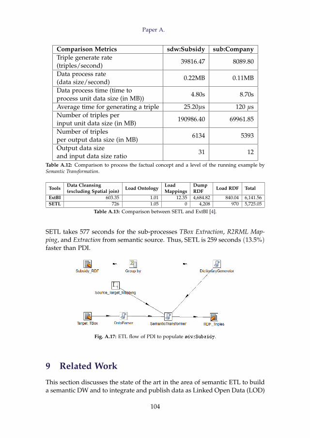
Paper A.
Comparison Metrics sdw:Subsidy sub:CompanyTriple generate rate(triples/second)
39816.47 8089.80
Data process rate(data size/second)
0.22MB 0.11MB
Data process time (time toprocess unit data size (in MB))
4.80s 8.70s
Average time for generating a triple 25.20µs 120 µsNumber of triples perinput unit data size (in MB)
190986.40 69961.85
Number of triplesper output data size (in MB)
6134 5393
Output data sizeand input data size ratio
31 12
Table A.12: Comparison to process the factual concept and a level of the running example bySemantic Transformation.
ToolsData Cleansing(excluding Spatial join)
Load OntologyLoadMappings
DumpRDF
Load RDF Total
ExtBI 603.35 1.01 12.35 4,684.82 840.04 6,141.56SETL 726 1.05 0 4,208 970 5,725.05
Table A.13: Comparison between SETL and ExtBI [4].
SETL takes 577 seconds for the sub-processes TBox Extraction, R2RML Map-ping, and Extraction from semantic source. Thus, SETL is 259 seconds (13.5%)faster than PDI.
Fig. A.17: ETL flow of PDI to populate sdw:Subsidy.
9 Related Work
This section discusses the state of the art in the area of semantic ETL to builda semantic DW and to integrate and publish data as Linked Open Data (LOD)
104
9. Related Work
from multiple sources.Recently, the use of SW technology in data warehouses has become pop-
ular. Some approaches have used ontologies as a data integration method formapping between sources and target whereas others have considered a datawarehouse as a repository of ontologies and its instances.
In [49, 50], an OWL ontology is used to link the schemas of semi-structuredand structured data to a target DW schema. At first, the schemas of the datasources and the DW are described by a common graph-based model nameddatastore graph. Then, an application ontology is constructed to describe thesemantics of the data sources and the DW, and mapping between them canbe done through that ontology. In this way, the heterogeneity issues amongthe schemas of sources and target have been resolved. In this work, it is as-sumed that source and target schemas are known beforehand. However, itdoes not consider the MD view over the DW. In [52], the authors have shownthat an ontological approach can automate and minimize the maintenancecost of the evolution of a DW schema. Here, they define every design step ofDW using ontology.
A framework for designing semantic DW has been proposed in [36]. Here,the usage of SW languages to integrate distributed DWs and to automate theETL process of a DW has been discussed. The DW has been consideredas a repository of ontologies and semantically annotated data sources. [8]proposes a methodology describing important steps required to create a se-mantic DW that enables to integrate data from semantic databases, which iscomposed of an ontology and its instances. A multidimensional (MD) frame-work has been proposed in [35] to analyze semantic data that are provided bythe SW and that are annotated by application and domain ontologies. It al-lows to build and populate a DW from both the analyst requirements and theknowledge encoded in the ontologies. In [56], authors have proposed a so-lution for supporting data integration tasks by constructing ontologies fromXML and relational sources and integrating the derived ontologies by meansof existing ontology alignment and merging techniques. However, ontologyalignment technique itself is a difficult and error-prone process [58].
In the past couple of years, publishing data in a machine-readable formathas become more popular and (Linked Open Data) LOD has emerged as away to share such data across Web sources. [60] presents a process to pub-lish governmental data as LOD and [4] discusses how to spatially integrateand publish a Danish Agricultural dataset and a Danish Business dataset asLOD. The approach uses views to cleanse the data and Virtuoso for creatingand storing RDF data. To integrate data from heterogeneous sources andpublish those data as LOD, a semantic ETL framework is presented in [7]at conceptual level. The approach uses the semantic technology to facilitatethe integration process and discusses the use of different tools to accomplishthe different steps of the ETL process. To enable warehouse-style analysis
105
Paper A.
over RDF data, some approaches [13, 26] propose the use of a native RDFdata warehouse. To analyze an RDF graph, [13] introduced a lens namedanalytical schema, which is a graph of classes and properties. Each nodeof the schema represents a set of facts, which can be analyzed by exploringthe reachable nodes. To enable OLAP-style analysis over Linked Data (LD),W3C recommend RDF Data Cube Vocabulary (QB vocabulary) to describethe RDF data in MD fashion [15]. However, it has limitations to fully definethe traditional MD constructs and it is mostly used to present the statisticaldata as LD. In [21], authors propose QB4OLAP model by extending the QBmodel to annotate an existing graph with MD constructs. To enable OLAPover LD datasets which contains numerical values, even if they are not an-notated either QB or QB4OLAP, in [30], authors proposed a SPARQL-basedETL framework.
Because of the decentralized structure and dynamic nature of LOD, some-times it is required to integrate external sources in a federated way. UnlikeDW, data federation avoids the need of materializing integrated data into acentralized warehouse. It emphasizes on logical rather than physical inte-gration of data. In [38], authors have proposed a theoretically well-foundedapproach to the logical federation of OLAP and XML data sources. A set ofquery processing strategies for executing OLAP-like SPARQL queries over afederation of SPARQL endpoint has been proposed in [25]. However, feder-ation techniques have an additional number of unique challenges on severallevels. Participating sources in a federation are autonomous, i.e., they mightbe unavailable at some point or change their data. So, for query process-ing, federations introduce delays because of the distribution and there is noguarantee that the data is still available or in the same state as when thefederation was created - both schema and data might have changed so thatthe integration rules might no longer be valid. So, a standard approach is toavoid federations and have a local copy of the data which is the focus of thisstudy. This guarantees that the data will be available and an answer to a userquery can be computed efficiently. Moreover, scalability is indeed a problemfor analytical queries in federations [25].
As data become outdated due to updates in the sources, using differenttools for extraction, validation, and integration becomes very tedious andtime consuming. Hence, a framework is necessary that makes it possibleto accomplish every step in a single platform. Although the state-of-the-art approaches provide different conceptual frameworks, there is no imple-mented programmable framework that facilitates the developers by provid-ing required tools, classes, and methods to build ETL process with the goalof either creating a semantic multidimensional DW or publishing the seman-tically integrated data as LOD. Hence, this paper discusses a semantic ETLframework, SETL, which provides various modules, classes, and methods toextract semantic-aware data, geo-spatial data, and other traditional data, to
106
10. Conclusion
integrate source data semantically using a target TBox defined with/with-out MD constructs, and to store the data as semantic data. SETL facilitatesdevelopers to build a semantic DW using a single platform instead of usingdifferent tools and a manual process.
10 Conclusion
Building a DW integrating internal and external data published in differentformats requires semantic integration. Here, we have proposed and devel-oped a programmable framework, named Semantic ETL (SETL) that facili-tates users to build a (MD) SDW. SETL uses TBox as an underlying schemato integrate heterogeneous data sources. To annotate the target TBox withMD constructs, it uses the constructs of QB4OLAP model. It allows to pro-cess both semantic and Non Semantic Data Sources. In order to processa Non Semantic Data Source, it builds a semantic layer on top of the Non
Semantic Data Source. Eventually, it stores the data as RDF triples basedon the MD semantics encoded in the target TBox. It also allows to link theinternal resources with external resources. In order to evaluate our frame-work, we produced a SDW by integrating a semantic and a Non Semantic
Data Sources. In Section 4, we show that SETL has good performance forall the steps and is faster than the competing tools/solutions.
The model behind a triplestore is an RDF graph. Another issue is how toimplement physically the store. We can choose graph, relational or Hadoop,but in this paper, we focus on increasing the abstraction level and thus theuser productivity. Therefore, physical or platform-dependent optimizationsremain for the future. Our future research also includes proposing a well-defined set of basic semantic ETL operators that can be combined to performany semantic ETL operations. Besides, developing techniques to explore theLinked Open Data cloud for the related dimensions and level and linkingthem with the internal ones are also in our consideration.
References
[1] A. Abelló, O. Romero, T. B. Pedersen, R. Berlanga, V. Nebot, M. J. Aramburu,and A. Simitsis, “Using Semantic Web Technologies for Exploratory OLAP: ASurvey,” TKDE, vol. 99, pp. 571–588, 2014.
[2] A. Abelló, J. Darmont, L. Etcheverry, M. Golfarelli, J.-N. Mazón, F. Naumann,T. Pedersen, S. B. Rizzi, J. Trujillo, P. Vassiliadis et al., “Fusion Cubes: TowardsSelf-Service Business Intelligence,” International Journal of Data Warehousing andMining (IJDWM), vol. 9, no. 2, pp. 66–88, 2013.
[3] A. Abelló, J. Samos, and F. Saltor, “YAM2: A Multidimensional ConceptualModel Extending UML,” Information Systems, vol. 31, no. 6, pp. 541–567, 2006.
107
References
[4] A. B. Andersen, N. Gür, K. Hose, K. A. Jakobsen, and T. B. Pedersen, “PublishingDanish Agricultural Government Data as Semantic Web Data,” in JIST, 2015.
[5] “ArcPy-ArcGIS Python Library, http://help.arcgis.com/en/arcgisdesktop/10.0/help/index.html#//000v00000001000000.”
[6] F. Baader, The Description Logic Handbook: Theory, Implementation and Applications.Cambridge university press, 2003.
[7] S. K. Bansal, “Towards a Semantic Extract-Transform-Load (ETL) Framework for Big Data Integration,” in Big Data, 2014, pp. 522–529.
[8] L. Bellatreche, S. Khouri, and N. Berkani, “Semantic Data Warehouse Design:From ETL to Deployment à la Carte,” in DASFAA, 2013, pp. 64–83.
[9] R. Berlanga, O. Romero, A. Simitsis, V. Nebot, T. B. Pedersen, A. Abelló, and M. J.Aramburu, “Semantic Web Technologies for Business Intelligence,” in BusinessIntelligence Applications and the Web: Models, Systems and Technologies. IGI global,2012, pp. 310–339.
[10] C. Bizer and A. Schultz, “The Berlin SPARQL Benchmark,” 2009.
[11] M. Casters, R. Bouman, and J. Van Dongen, Pentaho Kettle solutions: Building OpenSource ETL Solutions with Pentaho Data Integration. John Wiley & Sons, 2010.
[12] K. Christodoulou, N. W. Paton, and A. A. Fernandes, “Structure Inference forLinked Data Sources using Clustering,” in Transactions on Large-Scale Data-andKnowledge-Centered Systems XIX. Springer, 2015, pp. 1–25.
[13] D. Colazzo, F. Goasdoué, I. Manolescu, and A. Roatis, “RDF Analytics: Lensesover Semantic Graphs,” in WWW, 2014, pp. 467–478.
[14] “Danish Central Company Registry (CVR) Data, http://cvr.dk/.”
[15] R. Cyganiak, D. Reynolds, and J. Tennison, “The RDF Data Cube Vocabulary,”World Wide Web Consortium, 2014.
[16] “DBpedia, http://dbpedia.org/.”
[17] R. P. Deb Nath, K. Hose, and T. B. Pedersen, “Towards a Programmable SemanticExtract-Transform-Load Framework for Semantic Data Warehouses,” in Proceed-ings of the ACM Eighteenth International Workshop on Data Warehousing and OLAP.ACM, 2015, pp. 15–24.
[18] M. Ehrig, “Ontology Alignment: Bridging the Semantic Gap, volume 4 of Se-mantic Web And Beyond Computing for Human Experience,” 2007.
[19] “Esri, Arcgis. http://www.esri.com/software/arcgis.”
[20] L. Etcheverry, S. S. Gomez, and A. Vaisman, “Modeling and Querying DataCubes on the Semantic Web,” arXiv preprint arXiv:1512.06080, 2015.
[21] L. Etcheverry, A. Vaisman, and E. Zimányi, “Modeling and Querying Data Ware-houses on the Semantic Web Using QB4OLAP,” in DaWak, 2014, pp. 45–56.
[22] “Ministry of Food, Agriculture and Fisheries of Denmark, http://en.fvm.dk/.”
[23] M. Golfarelli and S. Rizzi, Data Warehouse Design: Modern Principles and Method-ologies. McGraw-Hill, Inc., 2009.
108
References
[24] A. Harth, K. Hose, and R. Schenkel, Linked Data Management. CRC Press, 2014.
[25] D. Ibragimov, K. Hose, T. B. Pedersen, and E. Zimányi, “Processing AggregateQueries in a Federation of SPARQL Endpoints,” in European Semantic Web Con-ference. Springer, 2015, pp. 269–285.
[26] K. A. Jakobsen, A. B. Andersen, K. Hose, and T. B. Pedersen, “Optimizing RDFData Cubes for Efficient Processing of Analytical Queries,” in COLD, 2015.
[27] “Apache Jena TDB, https://jena.apache.org/documentation/tdb/.”
[28] C. S. Jensen, T. B. Pedersen, and C. Thomsen, “Multidimensional Databases andData Warehousing,” Synthesis Lectures on Data Management, vol. 2, no. 1, pp. 1–111, 2010.
[29] R. Kimball and M. Ross, The Data Warehouse Toolkit: the Complete Guide to Dimen-sional Modeling. John Wiley & Sons, 2011.
[30] T. Komamizu, T. Amagasa, and H. Kitagawa, “SPOOL: A SPARQL-Based ETLFramework for OLAP over Linked Data,” in Proceedings of the 17th InternationalConference on Information Integration and Web-based Applications & Services. ACM,2015, p. 49.
[31] E. V. Kostylev, J. L. Reutter, and M. Ugarte, “CONSTRUCT Queries in SPARQL,”in LIPIcs-Leibniz International Proceedings in Informatics, vol. 31. Schloss Dagstuhl-Leibniz-Zentrum fuer Informatik, 2015.
[32] M. S. Kotoulas, F. van Harmelen, and J. Weaver, “KR and Reasoning on theSemantic Web: Web-Scale Reasoning,” in Handbook of Semantic Web Technologies.Springer, 2011, pp. 441–466.
[33] J. Li, J. Tang, Y. Li, and Q. Luo, “Rimom: A Dynamic Multistrategy OntologyAlignment Framework,” Knowledge and Data Engineering, IEEE Transactions on,vol. 21, no. 8, pp. 1218–1232, 2009.
[34] A. Nasiri, E. Zimányi, and R. Wrembel, “Requirements Engineering for DataWarehouses.” in EDA, 2015, pp. 49–64.
[35] V. Nebot and R. Berlanga, “Building Data Warehouses with Semantic Web Data,”DSS, vol. 52, no. 4, pp. 853–868, 2012.
[36] V. Nebot, R. Berlanga, J. M. Pérez, M. J. Aramburu, and T. B. Pedersen, “Multi-dimensional Integrated Ontologies: a Framework for Designing Semantic DataWarehouses,” JDS, vol. XIII, pp. 1–36, 2009.
[37] “OWL Web Ontology Language, www.w3.org/TR/owl-ref/.”
[38] D. Pedersen, K. Riis, and T. B. Pedersen, “XML-Extended OLAP Querying,” inScientific and Statistical Database Management, 2002. Proceedings. 14th InternationalConference on. IEEE, 2002, pp. 195–206.
[39] G. Petasis, V. Karkaletsis, G. Paliouras, A. Krithara, and E. Zavitsanos, “OntologyPopulation and Enrichment: State of the Art,” in Knowledge-driven multimediainformation extraction and ontology evolution. Springer-Verlag, 2011, pp. 134–166.
[40] “Petl - Extract, Transform and Load (Tables of Data), https://petl.readthedocs.org/en/latest/.”
109
References
[41] “Pyshp, https://code.google.com/p/pyshp/.”
[42] “Python, python.org as of 2015-03-25.”
[43] “R2RML: RDB to RDF Mapping Language https://www.w3.org/TR/2012/REC-r2rml-20120927/.”
[44] “Rdflib, https://github.com/RDFLib/rdflib.”
[45] M. Seddiqui, R. P. D. Nath, M. Aono et al., “An Efficient Metric of AutomaticWeight Generation for Properties in Instance Matching Technique,” arXiv preprintarXiv:1502.03556, 2015.
[46] M. H. Seddiqui, S. Das, I. Ahmed, R. P. D. Nath, and M. Aono, “Augmentationof Ontology Instance Matching by Automatic Weight Generation,” in Informationand Communication Technologies (WICT), 2011 World Congress on. IEEE, 2011, pp.1390–1395.
[47] J. Sequeda, F. Priyatna, and B. Villazón-Terrazas, “Relational Database to RDFMapping Patterns.” in WOP. Citeseer, 2012.
[48] “ESRI, Shapefile Technical Description, INC, 1998.”
[49] D. Skoutas and A. Simitsis, “Designing ETL Processes using Semantic Web Tech-nologies,” in DOLAP, 2006, pp. 67–74.
[50] ——, “Ontology-based Conceptual Design of ETL Processes for both Structuredand Semi-structured Data,” IJSWIS, vol. 3, no. 4, pp. 1–24, 2007.
[51] “SPARQLWrapper, http://rdflib.github.io/sparqlwrapper/.”
[52] M. Thenmozhi and K. Vivekanandan, “An Ontological Approach to Handle Mul-tidimensional Schema Evolution for Data Warehouse,” IJDMS, vol. 6, no. 4, pp.33–52, 2014.
[53] V. Theodorou, A. Abelló, and W. Lehner, “Quality Measures for ETL Processes,”in DaWaK, 2014, pp. 9–22.
[54] A. D. H. Thi and B. T. Nguyen, “A Semantic Approach Towards CWM-BasedETL Processes,” Proceedings of I-SEMANTICS, vol. 8, pp. 58–66, 2008.
[55] C. Thomsen and T. Bach Pedersen, “pygrametl: A Powerful ProgrammingFramework for Extract-Transform-Load Programmers,” in Proceedings of the ACMtwelfth international workshop on Data warehousing and OLAP. ACM, 2009, pp. 49–56.
[56] R. Touma, O. Romero, and P. Jovanovic, “Supporting Data Integration Tasks withSemi-Automatic Ontology Construction,” in Proceedings of the ACM EighteenthInternational Workshop on Data Warehousing and OLAP. ACM, 2015, pp. 89–98.
[57] G. Tummarello, R. Delbru, and E. Oren, “Sindice. com: Weaving the open linkeddata,” in ISWC, 2007.
[58] P. Tyl, “Ontology Matching for Web Services Composition,” in e-Technologies andNetworks for Development. Springer, 2011, pp. 94–103.
[59] A. Vaisman and E. Zimányi, Data Warehouse Systems: Design and Implementation.Springer, 2014.
110
References
[60] B. Villazón-Terrazas, L. M. Vilches-Blázquez, O. Corcho, and A. Gómez-Pérez, “AMethodological Guidelines for Publishing Government Linked Data,” in Linkinggovernment data, 2011, pp. 27–49.
[61] “W3C. Resource Description Framework, http://www.w3.org/RDF/.”
[62] “W3C. Resource Description Framework Schema, http://www.w3.org/TR/rdf-schema/.”
[63] S. Zhou, Z. Xu, Y. Ni, and H. Zhang, “R2RML Processor for Materializing RDFView of Relational Data: Algorithms and Experiments,” in Web Information Sys-tem and Application Conference (WISA), 2013 10th. IEEE, 2013, pp. 450–455.
[64] M. E. Zorrilla, J.-N. Mazón, Ó. Ferrández, I. Garrigós, F. Daniel, and J. Trujillo,Business Intelligence Applications and the Web: Models, Systems and Technologies.Business Science Reference, 2012.
111

References
112
Paper B
High-Level ETL for Semantic Data Warehouses
Rudra Pratap Deb Nath, Oscar Romero, Torben Bach Pedersen,and Katja Hose
The paper is submitted to Semantic Web Journal
Abstract
The popularity of the Semantic Web (SW) encourages organizations to organize andpublish data using the RDF model. This growth poses new requirements to BusinessIntelligence (BI) technologies to enable On-Line Analytical Processing (OLAP)-likeanalysis over RDF data. The incorporation of semantic data into a Data Warehouse(DW) is not supported by the traditional Extract-Transform-Load (ETL) tools be-cause they do not consider semantic issues in the integration process. In this paper,we propose a layer-based integration process and a set of high-level RDF-based ETLconstructs required to define, map, extract, process, transform, integrate, update, andload (multidimensional) semantic data. Different to other ETL tools, we automatethe ETL data flows by creating metadata at the schema level. Therefore, it relievesETL developers from the burden of manual mapping at the ETL operation level.We create a prototype, named Semantic ETL Construct (SETLCONSTRUCT), basedon the innovative ETL constructs proposed here and it is also extended to generateautomatic ETL data flows (we call it SETLAUTO) . To evaluate SETLCONSTRUCTand SETLAUTO, we create a multidimensional semantic DW by integrating a Dan-ish Business Dataset and an EU Subsidy dataset using it and compare it with theprevious programmable framework SETLPROG in terms of productivity, develop-ment time and performance. The evaluation shows that 1) SETLCONSTRUCT uses92% fewer Number of Typed Characters (NOTC) than SETLPROG, and SETLAUTOfurther reduces the Number of Used Concepts (NOUC) by another 25%; 2) usingSETLCONSTRUCT, the development time is almost cut in half compared to SETLPROG,and is cut by another 27% using SETLAUTO; 3) SETLCONSTRUCT is scalable and hassimilar performance compared to SETLPROG.
The layout has been revised.
1. Introduction
1 Introduction
Semantic Web technologies enable adding a semantic layer over the data;thus, the data can be processed and effectively retrieved by both humans andmachines. The Linked Data (LD) principles are the set of standard rules topublish and connect data using semantic links [23]. With the growing popu-larity of the SW and LD, more and more organizations natively manage datausing SW standards, such as Resource Description Framework (RDF), RDF-Schema (RDFs), the Web Ontology Language (OWL), etc. [13]. Moreover,one can easily convert data given in another format (database, XML, JSON,etc.) into RDF format using an RDF wrapper. As a result, a lot of seman-tic datasets are now available in different data portals, such as DataHub1,Linked Open Data Cloud 2 (LOD), etc. Most SW data provided by interna-tional and governmental organizations include facts and figures which giverise to new requirements for Business Intelligence (BI) tools to enable analy-ses in the style of Online Analytical Processing (OLAP) over those semanticdata [30].
OLAP is a well-recognized technology to support decision making by an-alyzing data integrated from multiple sources. The integrated data are storedin a Data Warehouse (DW), typically structured following the Multidimen-sional Model (MD) that represents data in terms of facts and dimensions toenable OLAP queries. The integration process for extracting data from dif-ferent sources, translating it according to the underlying semantics of theDW, and loading it into the DW is known as Extract-Transform-Load (ETL).One way to enable OLAP analysis over semantic data is by extracting thosedata and translating them according to the DW’s format using a traditionalETL process. [40] outlines such a type of semi-automatic method to inte-grate semantic data into a traditional RDBMS-centric MD DW. However, theprocess does not maintain all the semantics of data as they are conveyingin the semantic sources; hence the integrated data no more follow the SWdata principles defined in [24]. The semantics of the data in a semantic datasource is defined by 1) using Internationalized Resource Identifier (IRIs) touniquely identify resources globally, 2) providing common terminology, 3)semantically linking with published information, and 4) providing furtherknowledge (e.g., logical axioms) to allow reasoning [7].
Therefore, considering semantic issues in the integration process shouldbe emphasized. Moreover, initiatives such as Open Government Data3 en-courage organizations to publish their data using standards and non-propriet-ary formats [55]. The integration of semantic data into a DW raises thechallenges of schema derivation, semantic heterogeneity, semantic annota-
1https://datahub.io/2https://lod-cloud.net/3https://opengovdata.org/
115
Paper B.
tion, linking as well as the schema and data management system over tra-ditional DW technologies and ETL tools. The main drawback of a state-of-the-art Relational Database Management System (RDBMS)-based DW is thatit is strictly schema dependent and less flexible to evolving business require-ments. To cover new business requirements, every step of the developmentcycle needs to be updated to cope with the new requirements. This updateprocess is time-consuming as well as costly and is sometimes not adjustablewith the current setup of the DW; hence it introduces the need for a novelapproach. The limitations of traditional ETL tools to process semantic datasources are: (1) they do not fully support semantic-aware data, (2) they areentirely schema dependent (i.e., cannot handle data expressed without pre-defined schema), (3) they do not focus on meaningful semantic relationshipsto integrate data from disparate sources, and (4) they neither support to cap-ture the semantics of data nor support to derive new information by activeinference and reasoning on the data.
Semantic Web technologies address the problems described above, as theyallow adding semantics at both data and schema level in the integration pro-cess and publish data in RDF using the LD principles. On the SW, the RDFmodel is used to manage and exchange data, and RDFS and OWL are usedin combination with the RDF data model to define constraints that data mustmeet. Moreover, QB [9] and QB4OLAP [15] vocabularies can be used todefine data with MD semantics. [37] refers to an MD DW that is semanti-cally annotated both at the schema and data level as a Semantic DW (SDW).An SDW is based on the assumption that the schema can evolve and beextended without affecting the existing structure. Hence, it overcomes theproblems triggered by the evolution of an RDBMS-based data warehousingsystem. In [37], we proposed SETL (throughout this present paper, we callit SETLPROG), a programmable semantic ETL framework that semanticallyintegrates both semantic and non-semantic data sources. In SETLPROG, anETL designer has to create hand-code specific modules to deal with semanticdata. Thus, there is a lack of a well-defined set of basic ETL constructs thatallow developers having a higher level of abstraction and more control increating their ETL process. In this paper, we propose a strong foundation foran RDF-based semantic integration process and a set of high-level ETL con-structs that allows defining, mapping, processing, and integrating semanticdata. The unique contributions of this paper are:
1. We structure the integration process into two layers: Definition Layerand Execution Layer. Different to SETL or other ETL tools, here, wepropose a new paradigm: the ETL flow transformations are character-ized once and for all at the Definition Layer instead of independentlywithin each ETL operation (in the Execution Layer). This is done bygenerating a mapping file that gives an overall view of the integration
116
1. Introduction
process. This mapping file is our primary metadata source, and it willbe fed to the ETL operators, orchestrated in the ETL flow (ExecutionLayer), to parametrize themselves automatically. Thus, we are unifyingthe creation of the required metadata to automate the ETL process inthe Definition layer. We propose an OWL-based Source-To-target Map-ping (S2TMAP) vocabulary to express the source-to-target mappings.
2. We provide a set of high-level ETL constructs for each layer. The Def-inition Layer includes constructs for target schema4 definition, sourceschema derivation, and source-to-target mappings generation. The Ex-ecution Layer includes a set of high-level ETL operations for semanticdata extraction, cleansing, joining, MD data creation, linking, inferenc-ing, and for dimensional data update.
3. We propose an approach to automate the ETL execution flows based onmetadata generated in the Definition Layer.
4. We create a prototype SETLCONSTRUCT, based on the innovative ETLconstructs proposed here. SETLCONSTRUCT allows creating ETL flows bydragging, dropping, and connecting the ETL operations. In addition, itallows creating ETL data flows automatically (we call it SETLAUTO).
5. We perform a comprehensive experimental evaluation by producingan MD SDW that integrates an EU farm Subsidy dataset and a Dan-ish Business dataset. The evaluation shows that SETLCONSTRUCT im-proves considerably over SETLPROG in terms of productivity, develop-ment time, and performance. In summary: 1) SETLCONSTRUCT uses92% fewer Number of Typed Characters (NOTC) than SETLPROG, andSETLAUTO further reduces the Number of Used Concepts (NOUC) byanother 25%; 2) using SETLCONSTRUCT, the development time is almostcut in half compared to SETLPROG, and is cut by another 27% usingSETLAUTO; 3) SETLCONSTRUCT is scalable and has similar performancecompared to SETLPROG.
The remainder of the paper is organized as follows. We discuss the termi-nologies and the notations used throughout the paper in Section 2. Section 3explains the structure of the datasets we use as use case. Section 4 givesthe overview of an integration process. The description of the DefinitionLayer and Execution Layer constructs are given in Sections 5 and 6, respec-tively. Section 7 presents the automatic ETL data flow generation process. InSection 8, we create an MD SDW for a use case using SETLCONSTRUCT andcompare the process with SETLPROG using different metrics. The previousresearch related to our study is discussed in Section 9. Finally, we concludeand give pointers to future work in Section 10.
4Here, we use the terms “target" and “MD SDW" interchangeably.
117
Paper B.
2 Preliminary Definitions
In this section, we provide the definitions of the notions and terminologiesused throughout the paper.
2.1 RDF Graph
An RDF graph is represented as a set of statements, called RDF triples. Thethree parts of a triple are subject, predicate, and object, respectively, and atriple represents a relationship between its subject and object described by its
predicate. Each triple, in the RDF graph, is represented as subjectpredicate−−−−→
object, where subject and object of the triple are the nodes of the graph, andthe label corresponds to the predicate of the triple. Given I, B, and L are thesets of IRIs, blank nodes, and literals, and (I ∩ B ∩ L) = ∅, an RDF triple is(s, p, o), where s ∈ (I ∪ B), p ∈ I , and o ∈ (I ∪ B ∪ L). An RDF graph G is aset of RDF triples, where G ⊆ (I ∪ B)× I × (I ∪ B ∪ L) [22].
2.2 Semantic Data Source
We define a semantic data source as a Knowledge Base (KB) where data aresemantically defined. A KB is composed of two components, TBox and ABox.The TBox introduces terminology, the vocabulary of a domain, and the ABoxis the assertions of the TBox. The TBox is formally defined as a 3-tuple:TBox = (C, P, AO), where C, P, and AO are the sets of concepts, properties,and terminological axioms, respectively [4]. Generally, a concept5 provides ageneral framework for a group of instances that have similar properties. Aproperty either relates the instances of concepts or associates the instances ofa concept to literals. Terminological axioms are used to describe the domain’sconcepts, properties, and the relationships and constraints among them. Inthis paper, we consider a KB as an RDF graph; therefore, the componentsof the KB are described by a set of RDF triples. Some standard languagessuch as Resource Description Framework Schema (RDFS) and Web OntologyLanguage (OWL) provide standard terms to define the formal semantics ofa TBox. In RDFS, the core classes rdfs:Class, and rdf:Property are usedto define the concepts and properties of a TBox; one can distinguish betweeninstances and classes by using the rdf:type property, express concept andproperty taxonomies by using rdfs:subClassOf and rdfs:subPropertyOf,and specify the domain and range of properties by using the rdfs:domain
and rdfs:range properties. Similarly, OWL uses owl:Class to define con-cepts and either owl:DataTypeProperty or owl:ObjectProperty for prop-erties. In addition to rdfs:subClassOf, it uses owl:equivalentClass and
5In this paper, we use the terms “concept" and “class" interchangeably.
118
2. Preliminary Definitions
owl:disjointWith constructs for class axioms to give additional characteris-tics of classes. Property axioms define additional characteristics of properties.In addition to supporting RDFS constructs for property axioms, OWL pro-vides owl:equivalentProeprty and owl:inverseOf to relate different prop-erties, provides owl:FunctionalProperty and owl:InverseFunctionalProp-
erty for imposing global cardinality constraints, and supports owl:Symmetri-cProperty and owl:TransitivityProperty for characterizing the relation-ship type of properties. As a KB can be defined by either language or both,we generalize the definition of C and P in a TBox T as C(T) = {c| type(c) ∈P({rdfs:Class, owl:Class})} and P(T) = {p| type(p) ∈ P({rdf:Property,owl:ObjectProperty, owl:DatatypeProperty})}, respectively, where type(x)returns the set of classes of x, i.e., (x rdf:type ?type(x))— it returns the set ofthe objects of the triples whose subjects and predicates are x and rdf:type,respectively— and P(s) is the power set of s.
2.3 Semantic Data Warehouse
A semantic data warehouse (SDW) is a DW with the semantic annotations.We also considered it as a KB. Since the DW is represented with Multidi-mensional (MD) model for enabling On-Line Analytical Processing (OLAP)queries, the KB for an SDW needs to be defined with MD semantics. Inthe MD model, data are viewed in an n-dimensional space, usually knownas a data cube, composed of facts (the cells of the cube) and dimensions(the axes of the cube). Therefore, it allows users to analyze data alongseveral dimensions of interest. For example, a user can analyze sales ofproducts according to time and store (dimensions). Facts are the interest-ing things or processes to be analyzed (e.g., sales of products) and the at-tributes of the fact are called measures (e.g., quantity, amount of sales), usu-ally represented as numeric values. A dimension is organized into hierar-chies, composed of several levels, which permit users to explore and aggre-gate measures at various levels of detail. For example, the location hierarchy(municipality → region → state → country) of the store dimension allows toaggregate the sales at various levels of detail.
We use the QB4OLAP vocabulary to describe the multidimensional se-mantics over a KB [15]. QB4OLAP is used to annotate the TBox with MDcomponents and is based on the RDF Data Cube (QB) which is the W3Cstandard to publish MD data on the Web [12]. The QB is mostly used foranalyzing statistical data and does not adequately support OLAP MD con-structs. Therefore, in this paper, we choose QB4OLAP. Figure B.1 depictsthe ontology of QB4OLAP [55]. The terms prefixed with “qb:” are from theoriginal QB vocabulary, and QB4OLAP terms are prefixed with “qb4o:” anddisplayed with gray background. Capitalized terms represent OWL classes,and non-capitalized terms represent OWL properties. Capitalized terms in
119
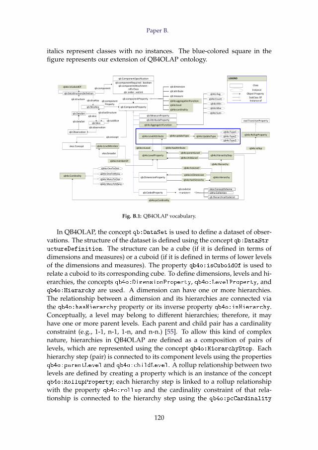
Paper B.
italics represent classes with no instances. The blue-colored square in thefigure represents our extension of QB4OLAP ontology.
qb:DataStructureDefinition
qb:DataSet
qb:Observation
qb:SliceKey
qb:Slice
qb:ComponentProperty
qb:ComponentSpecification
qb:componentRequired : booleanqb:componentAttachment :
rdfs:Classqb :order : xsd:int
qb:ComponentSpecification
qb:componentRequired : booleanqb:componentAttachment :
rdfs:Classqb :order : xsd:int
skos:Concept
qb4o:AggregatinFunction
qb4o:LevelMember
qb:MeasureProperty
qb:AttributeProperty
qb:DimensionProperty
qb4o:LevelAttribute
qb4o:LevelProperty qb4o:HierarchyStep
qb4o:Hierarchy
qb4o:RollupProperty
qb4o:Cardinality
qb4o:Avg
qb4o:Count
qb4o:MIn
qb4o:Max
qb4o:Sum
qb4o:UpdateType
qb4o:OneToOne
qb4o:OneToMany
qb4o:ManyToOne
qb4o:ManyToMany
qb4o:OneToOne
qb4o:OneToMany
qb4o:ManyToOne
qb4o:ManyToMany
qb4o:inLevel qb4o:hasAttribute
qb4o:Type1
qb4o:Type2
qb4o:Type3
qb4o:Type1
qb4o:Type2
qb4o:Type3
qb4o:isCuboidOf
qb:sliceKeyqb:structure
qb:sliceStructure
qb:slice
qb:observation
qb:subSlice
qb:componentProperty
qb:component
qb4o:cardinality
qb4o:level
qb4o:aggregationFunction
qb:measure
qb:attribute
qb:dimension
qb4o:cardinality
qb4o:level
qb4o:aggregationFunction
qb:measure
qb:attribute
qb:dimension
qb4o:cardinality
qb4o:level
qb4o:aggregationFunction
qb:measure
qb:attribute
qb:dimension
qb4o:cardinality
qb4o:level
qb4o:aggregationFunction
qb:measure
qb:attribute
qb:dimension
qb:concept
skos:broader
qb:CodedProperty
qb4o:parentLevelqb4o:parentLevel
qb4o:childLevelqb4o:childLevel
qb4o:Hierarchy
qb4o:rollup
owl:TransitiveProperty
qb4o:memberOf
qb4o:inDimensionqb4o:inDimension
qb4o:hasHierarchyqb4o:hasHierarchy
qb:HierarchicalCodeList
sdmx:Collection
skos:ConceptScheme
qb:HierarchicalCodeList
sdmx:Collection
skos:ConceptScheme
qb:HierarchicalCodeList
sdmx:Collection
skos:ConceptScheme
qb:HierarchicalCodeList
sdmx:Collection
skos:ConceptScheme
<<union>>
qb:codeList
qb4o:hasLevel
qb4o:pcCardinality
qb4o:updateType
qb:componentProperty
LEGEND
Class
Instance
Object Property
SubClass OfInstance of
LEGEND
Class
Instance
Object Property
SubClass OfInstance of
qb:dataSet
Fig. B.1: QB4OLAP vocabulary.
In QB4OLAP, the concept qb:DataSet is used to define a dataset of obser-vations. The structure of the dataset is defined using the concept qb:DataStr-uctureDefinition. The structure can be a cube (if it is defined in terms ofdimensions and measures) or a cuboid (if it is defined in terms of lower levelsof the dimensions and measures). The property qb4o:isCuboidOf is used torelate a cuboid to its corresponding cube. To define dimensions, levels and hi-erarchies, the concepts qb4o:DimensionProperty, qb4o:LevelProperty, andqb4o:Hierarchy are used. A dimension can have one or more hierarchies.The relationship between a dimension and its hierarchies are connected viathe qb4o:hasHierarchy property or its inverse property qb4o:inHierarchy.Conceptually, a level may belong to different hierarchies; therefore, it mayhave one or more parent levels. Each parent and child pair has a cardinalityconstraint (e.g., 1-1, n-1, 1-n, and n-n.) [55]. To allow this kind of complexnature, hierarchies in QB4OLAP are defined as a composition of pairs oflevels, which are represented using the concept qb4o:HierarchyStep. Eachhierarchy step (pair) is connected to its component levels using the propertiesqb4o:parentLevel and qb4o:childLevel. A rollup relationship between twolevels are defined by creating a property which is an instance of the conceptqb4o:RollupProperty; each hierarchy step is linked to a rollup relationshipwith the property qb4o:rollup and the cardinality constraint of that rela-tionship is connected to the hierarchy step using the qb4o:pcCardinality
120
3. A Use Case
property. A hierarchy step is attached to the hierarchies it belongs to usingthe property qb4o:inHierarchy [15]. The concept qb4o:LevelAttributes isused to define attributes of levels. We extend this QB4OLAP ontology (theblue-colored box in the figure) to enable different types of dimension up-dates (Type 1, Type 2, and Type 3) to accommodate dimension update in anSDW, which are defined by Ralph Kimball in [32]. To define the update-type of a level attribute in the TBox level, we introduce the qb4o:UpdateType
class whose instances are qb4o:Type1, qb4o:Type1 and qb4o:Type3. A levelattribute is connected to its update-type by the property qb4o:updateType.The level attributes are linked to its corresponding levels using the propertyqb4o:hasAttribute. We extend the definition of C and P of a TBox, T for anSDW as
C(T) = {c| type(c) ∈ P({rdfs:Class, owl:Class, qb:DataStructureDef-
inition, qb:DataSet, qb:DimensionProperty, qb4o:LevelProperty,
qb4o:Hierarchy, qb4o:HierarchyStep})} (B.1)
P(T) = {p| type(p) ∈ P({rdf:Property, owl:ObjectProperty,
owl:DatatypeProperty, qb4o:LevelAttribute,
qb:MeassureProperty, qb4o:RollupProperty})} (B.2)
3 A Use Case
We create a Semantic Data Warehouse (SDW) by integrating two data sources,namely, a Danish Agriculture and Business knowledge base and an EU FarmSubsidy dataset. Both data sources are described below.
Description of Danish Agriculture and Business knowledge base TheDanish Agriculture and Business knowledge base integrates a Danish Agri-cultural dataset and a Danish Business dataset. The knowledge base canbe queried through the SPARQL endpoint http://extbi.lab.aau.dk:8080/sparql/. In our use case, we only use the business related information fromthis knowledge base and call it the Danish Business dataset (DBD). The rel-evant portion of the ontology of the knowledge base is illustrated in FigureB.2. Generally, in an ontology, a concept provides a general description ofthe properties and behavior for the similar type of resources; an object prop-erty relates among the instances of concepts; a data type property is used toassociate the instances of a concept to literals.
We start the description from the concept bus:Owner. This concept con-tains information about the owners of companies, the type of the owner-
121
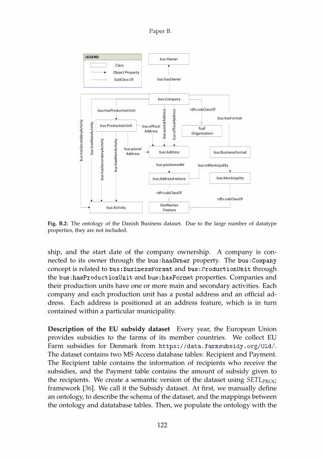
Paper B.
LEGEND
Class
Object Property
SubClass Of
LEGEND
Class
Object Property
SubClass Of
bus:Owner
bus:Company
bus:Activity
bus:ProductionUnit
bus:Address bus:BusinesxFormat
foaf:Organization
bus:AddressFeature
GeoNames:Feature
bus:Municipality
Fig. B.2: The ontology of the Danish Business dataset. Due to the large number of datatypeproperties, they are not included.
ship, and the start date of the company ownership. A company is con-nected to its owner through the bus:hasOwner property. The bus:Company
concept is related to bus:BusinessFormat and bus:ProductionUnit throughthe bus:hasProductionUnit and bus:hasFormat properties. Companies andtheir production units have one or more main and secondary activities. Eachcompany and each production unit has a postal address and an official ad-dress. Each address is positioned at an address feature, which is in turncontained within a particular municipality.
Description of the EU subsidy dataset Every year, the European Unionprovides subsidies to the farms of its member countries. We collect EUFarm subsidies for Denmark from https://data.farmsubsidy.org/Old/.The dataset contains two MS Access database tables: Recipient and Payment.The Recipient table contains the information of recipients who receive thesubsidies, and the Payment table contains the amount of subsidy given tothe recipients. We create a semantic version of the dataset using SETLPROGframework [36]. We call it the Subsidy dataset. At first, we manually definean ontology, to describe the schema of the dataset, and the mappings betweenthe ontology and datatabase tables. Then, we populate the ontology with the
122
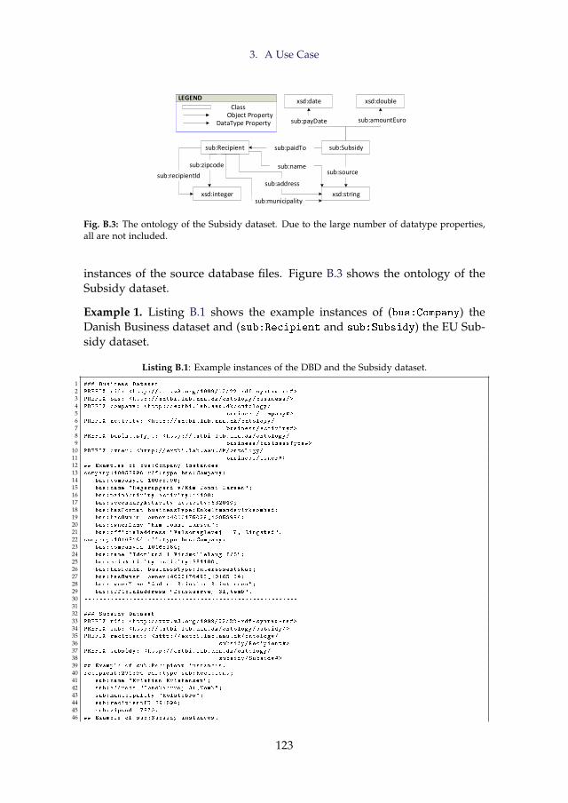
3. A Use Case
xsd:doublexsd:date
sub:Subsidy
xsd:string
sub:payDate sub:amountEuro
xsd:integer
sub:Recipient
sub:zipcode
sub:paidTo
sub:recipientId
LEGEND
ClassObject Property
DataType Property
LEGEND
ClassObject Property
DataType Property
sub:municipality
sub:source
sub:address
sub:name
Fig. B.3: The ontology of the Subsidy dataset. Due to the large number of datatype properties,all are not included.
instances of the source database files. Figure B.3 shows the ontology of theSubsidy dataset.
Example 1. Listing B.1 shows the example instances of (bus:Company) theDanish Business dataset and (sub:Recipient and sub:Subsidy) the EU Sub-sidy dataset.
Listing B.1: Example instances of the DBD and the Subsidy dataset.
1 ### Business Dataset
2 PREFIX rdf: <http ://www.w3.org /1999/02/22 -rdf -syntax -ns#>
3 PREFIX bus: <http :// extbi.lab.aau.dk/ontology/business/>
4 PREFIX company: <http :// extbi.lab.aau.dk/ontology/
5 business/Company#>
6 PREFIX activity: <http :// extbi.lab.aau.dk/ontology/
7 business/Activity#>
8 PREFIX businessType: <http :// extbi.lab.aau.dk/ontology/
9 business/BusinessType#>
10 PREFIX owner: <http :// extbi.lab.aau.dk/ontology/
11 business/Owner#>
12 ## Examples of bus:Company instances
13 company :10058996 rdf:type bus:Company;
14 bus:companyId 10058996;
15 bus:name "Regerupgard v/Kim Jonni Larsen";
16 bus:mainActivity activity :11100;
17 bus:secondaryActivity activity :682040;
18 bus:hasFormat businessType:Enkeltmandsvirksomhed:
19 bus:hasOwner owner :4000175029 _10058996;
20 bus:ownerName "Kim Jonni Larsen";
21 bus:officialaddress "Valsomaglevej 117, Ringsted".
22 company :10165164 rdf:type bus:Company;
23 bus:companyId 10165164;
24 bus:name "Idomlund 1 Vindmollelaug I/S";
25 bus:mainActivity activity :351100;
26 bus:hasFormat businessType:Interessentskab;
27 bus:hasOwner owner :4000170495 _10165164;
28 bus:ownerName "Anders Kristian Kristensen";
29 bus:officialaddress "Donskaervej 31,Vemb".
30 ---------------------------------------------------------
31 ---------------------------------------------------------
32 ### Subsidy Dataset
33 PREFIX rdf: <http ://www.w3.org /1999/02/22 -rdf -syntax -ns#>
34 PREFIX sub: <http :// extbi.lab.aau.dk/ontology/subsidy/>
35 PREFIX recipient: <http :// extbi.lab.aau.dk/ontology/
36 subsidy/Recipient#>
37 PREFIX subsidy: <http :// extbi.lab.aau.dk/ontology/
38 subsidy/Subsidy#>
39 ## Example of sub:Recipient instances.
40 recipient :291894 rdf:type sub:Recipient;
41 sub:name "Kristian Kristensen";
42 sub:address "Donskaervej 31,Vemb";
43 sub:municipality "Holstebro";
44 sub:recipientID 291894;
45 sub:zipcode 7570.
46 ## Example of sub:Subsidy instances.
123
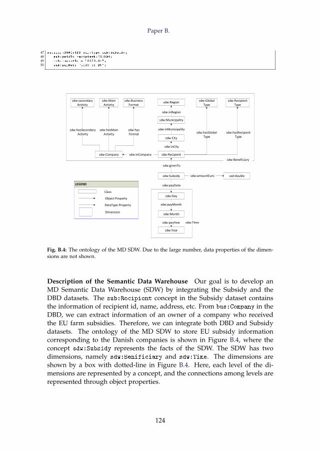
Paper B.
47 subsidy :10615413 rdf:type sub:Subsidy;
48 sub:paidTo recipient :291894;
49 sub:amountEuro "8928.31";
50 sub:payDate "2010 -05 -25";
sdw:Recipient
sdw:Day
sdw:Subsidy
sdw:Municipality
sdw:City
sdw:Region
sdw:Month
sdw:Year
sdw:Company
sdw:secondaryActivity
sdw:MainActivity
sdw:BusinessFormat
sdw:Global Type
sdw:RecipientType
sdw:inCompany
sdw:payDate
sdw:payMonth
sdw:payYear
sdw:hasSecondaryActivity
sdw:hasMainActivity
sdw:hasFormat
sdw:inMunicipality
sdw:inCity
sdw:inRegion
sdw:hasRecipientType
sdw:hasGlobalType
sdw:givenTo
xsd:doublesdw:amountEuro
sdw:Beneficiary
sdw:Time
LEGEND
Class
Object Property
DataType Property
LEGEND
Class
Object Property
DataType Property
Dimension
Fig. B.4: The ontology of the MD SDW. Due to the large number, data properties of the dimen-sions are not shown.
Description of the Semantic Data Warehouse Our goal is to develop anMD Semantic Data Warehouse (SDW) by integrating the Subsidy and theDBD datasets. The sub:Recipient concept in the Subsidy dataset containsthe information of recipient id, name, address, etc. From bus:Company in theDBD, we can extract information of an owner of a company who receivedthe EU farm subsidies. Therefore, we can integrate both DBD and Subsidydatasets. The ontology of the MD SDW to store EU subsidy informationcorresponding to the Danish companies is shown in Figure B.4, where theconcept sdw:Subsidy represents the facts of the SDW. The SDW has twodimensions, namely sdw:Benificiary and sdw:Time. The dimensions areshown by a box with dotted-line in Figure B.4. Here, each level of the di-mensions are represented by a concept, and the connections among levels arerepresented through object properties.
124
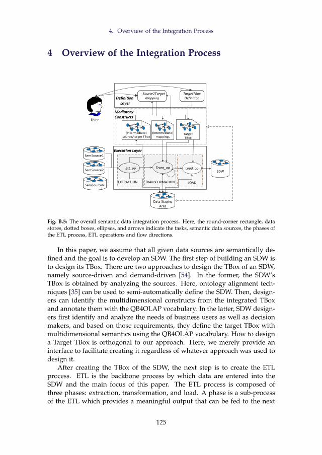
4. Overview of the Integration Process
4 Overview of the Integration Process
Load_op
EXTRACTION LOAD
Ext_opExt_op Trans_op
Source2TargetMapping
Source2TargetMapping
TargetTBoxDefinition
TargetTBoxDefinition
TRANSFORMATION
Execution Layer
Definition Layer
User
SemSourceNSemSourceN
SemSource1SemSource1
SemSource2SemSource2
Data Staging Area
Data Staging Area
SDWSDW
Mediatory Constructs
Fig. B.5: The overall semantic data integration process. Here, the round-corner rectangle, datastores, dotted boxes, ellipses, and arrows indicate the tasks, semantic data sources, the phases ofthe ETL process, ETL operations and flow directions.
In this paper, we assume that all given data sources are semantically de-fined and the goal is to develop an SDW. The first step of building an SDW isto design its TBox. There are two approaches to design the TBox of an SDW,namely source-driven and demand-driven [54]. In the former, the SDW’sTBox is obtained by analyzing the sources. Here, ontology alignment tech-niques [35] can be used to semi-automatically define the SDW. Then, design-ers can identify the multidimensional constructs from the integrated TBoxand annotate them with the QB4OLAP vocabulary. In the latter, SDW design-ers first identify and analyze the needs of business users as well as decisionmakers, and based on those requirements, they define the target TBox withmultidimensional semantics using the QB4OLAP vocabulary. How to designa Target TBox is orthogonal to our approach. Here, we merely provide aninterface to facilitate creating it regardless of whatever approach was used todesign it.
After creating the TBox of the SDW, the next step is to create the ETLprocess. ETL is the backbone process by which data are entered into theSDW and the main focus of this paper. The ETL process is composed ofthree phases: extraction, transformation, and load. A phase is a sub-processof the ETL which provides a meaningful output that can be fed to the next
125
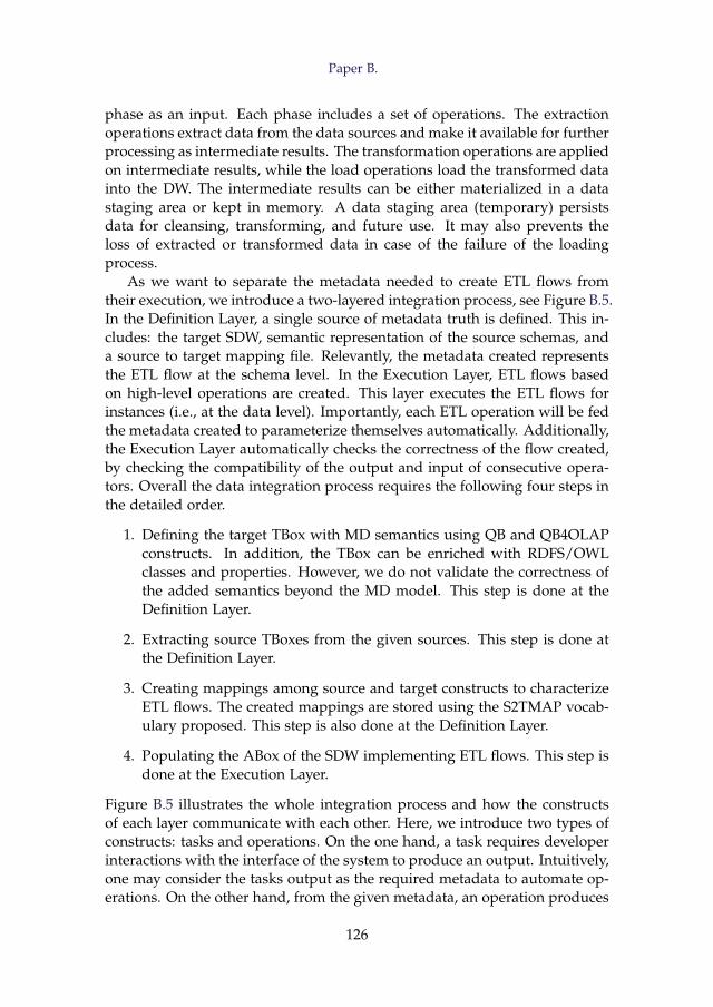
Paper B.
phase as an input. Each phase includes a set of operations. The extractionoperations extract data from the data sources and make it available for furtherprocessing as intermediate results. The transformation operations are appliedon intermediate results, while the load operations load the transformed datainto the DW. The intermediate results can be either materialized in a datastaging area or kept in memory. A data staging area (temporary) persistsdata for cleansing, transforming, and future use. It may also prevents theloss of extracted or transformed data in case of the failure of the loadingprocess.
As we want to separate the metadata needed to create ETL flows fromtheir execution, we introduce a two-layered integration process, see Figure B.5.In the Definition Layer, a single source of metadata truth is defined. This in-cludes: the target SDW, semantic representation of the source schemas, anda source to target mapping file. Relevantly, the metadata created representsthe ETL flow at the schema level. In the Execution Layer, ETL flows basedon high-level operations are created. This layer executes the ETL flows forinstances (i.e., at the data level). Importantly, each ETL operation will be fedthe metadata created to parameterize themselves automatically. Additionally,the Execution Layer automatically checks the correctness of the flow created,by checking the compatibility of the output and input of consecutive opera-tors. Overall the data integration process requires the following four steps inthe detailed order.
1. Defining the target TBox with MD semantics using QB and QB4OLAPconstructs. In addition, the TBox can be enriched with RDFS/OWLclasses and properties. However, we do not validate the correctness ofthe added semantics beyond the MD model. This step is done at theDefinition Layer.
2. Extracting source TBoxes from the given sources. This step is done atthe Definition Layer.
3. Creating mappings among source and target constructs to characterizeETL flows. The created mappings are stored using the S2TMAP vocab-ulary proposed. This step is also done at the Definition Layer.
4. Populating the ABox of the SDW implementing ETL flows. This step isdone at the Execution Layer.
Figure B.5 illustrates the whole integration process and how the constructsof each layer communicate with each other. Here, we introduce two types ofconstructs: tasks and operations. On the one hand, a task requires developerinteractions with the interface of the system to produce an output. Intuitively,one may consider the tasks output as the required metadata to automate op-erations. On the other hand, from the given metadata, an operation produces
126
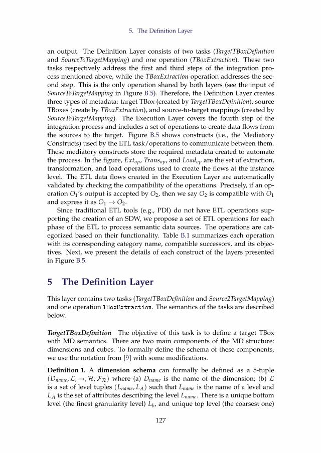
5. The Definition Layer
an output. The Definition Layer consists of two tasks (TargetTBoxDefinitionand SourceToTargetMapping) and one operation (TBoxExtraction). These twotasks respectively address the first and third steps of the integration pro-cess mentioned above, while the TBoxExtraction operation addresses the sec-ond step. This is the only operation shared by both layers (see the input ofSourceToTargetMapping in Figure B.5). Therefore, the Definition Layer createsthree types of metadata: target TBox (created by TargetTBoxDefinition), sourceTBoxes (create by TBoxExtraction), and source-to-target mappings (created bySourceToTargetMapping). The Execution Layer covers the fourth step of theintegration process and includes a set of operations to create data flows fromthe sources to the target. Figure B.5 shows constructs (i.e., the MediatoryConstructs) used by the ETL task/operations to communicate between them.These mediatory constructs store the required metadata created to automatethe process. In the figure, Extop, Transop, and Loadop are the set of extraction,transformation, and load operations used to create the flows at the instancelevel. The ETL data flows created in the Execution Layer are automaticallyvalidated by checking the compatibility of the operations. Precisely, if an op-eration O1’s output is accepted by O2, then we say O2 is compatible with O1and express it as O1 → O2.
Since traditional ETL tools (e.g., PDI) do not have ETL operations sup-porting the creation of an SDW, we propose a set of ETL operations for eachphase of the ETL to process semantic data sources. The operations are cat-egorized based on their functionality. Table B.1 summarizes each operationwith its corresponding category name, compatible successors, and its objec-tives. Next, we present the details of each construct of the layers presentedin Figure B.5.
5 The Definition Layer
This layer contains two tasks (TargetTBoxDefinition and Source2TargetMapping)and one operation TBoxExtraction. The semantics of the tasks are describedbelow.
TargetTBoxDefinition The objective of this task is to define a target TBoxwith MD semantics. There are two main components of the MD structure:dimensions and cubes. To formally define the schema of these components,we use the notation from [9] with some modifications.
Definition 1. A dimension schema can formally be defined as a 5-tuple(Dname,L,→,H,FR) where (a) Dname is the name of the dimension; (b) Lis a set of level tuples (Lname, LA) such that Lname is the name of a level andLA is the set of attributes describing the level Lname. There is a unique bottomlevel (the finest granularity level) Lb, and unique top level (the coarsest one)
127
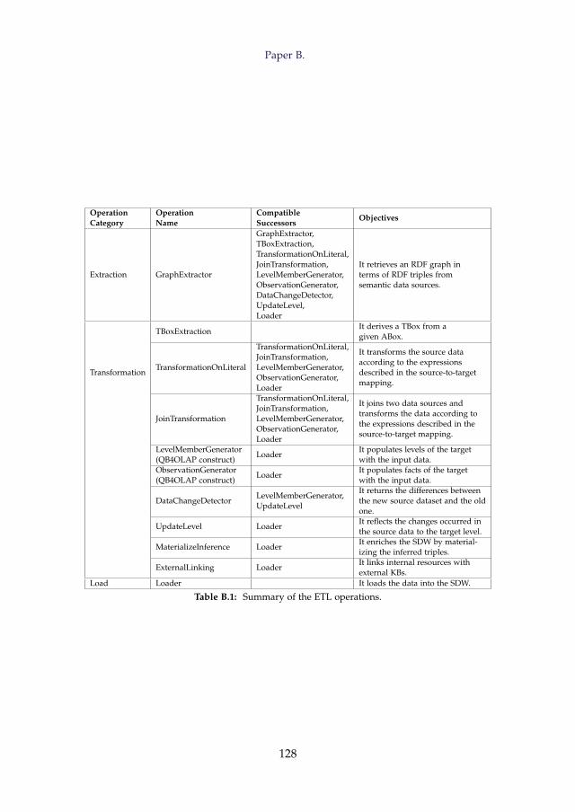
Paper B.
OperationCategory
OperationName
CompatibleSuccessors
Objectives
Extraction GraphExtractor
GraphExtractor,TBoxExtraction,TransformationOnLiteral,JoinTransformation,LevelMemberGenerator,ObservationGenerator,DataChangeDetector,UpdateLevel,Loader
It retrieves an RDF graph interms of RDF triples fromsemantic data sources.
Transformation
TBoxExtractionIt derives a TBox from agiven ABox.
TransformationOnLiteral
TransformationOnLiteral,JoinTransformation,LevelMemberGenerator,ObservationGenerator,Loader
It transforms the source dataaccording to the expressionsdescribed in the source-to-targetmapping.
JoinTransformation
TransformationOnLiteral,JoinTransformation,LevelMemberGenerator,ObservationGenerator,Loader
It joins two data sources andtransforms the data according tothe expressions described in thesource-to-target mapping.
LevelMemberGenerator(QB4OLAP construct)
LoaderIt populates levels of the targetwith the input data.
ObservationGenerator(QB4OLAP construct)
LoaderIt populates facts of the targetwith the input data.
DataChangeDetectorLevelMemberGenerator,UpdateLevel
It returns the differences betweenthe new source dataset and the oldone.
UpdateLevel LoaderIt reflects the changes occurred inthe source data to the target level.
MaterializeInference LoaderIt enriches the SDW by material-izing the inferred triples.
ExternalLinking LoaderIt links internal resources withexternal KBs.
Load Loader It loads the data into the SDW.
Table B.1: Summary of the ETL operations.
128
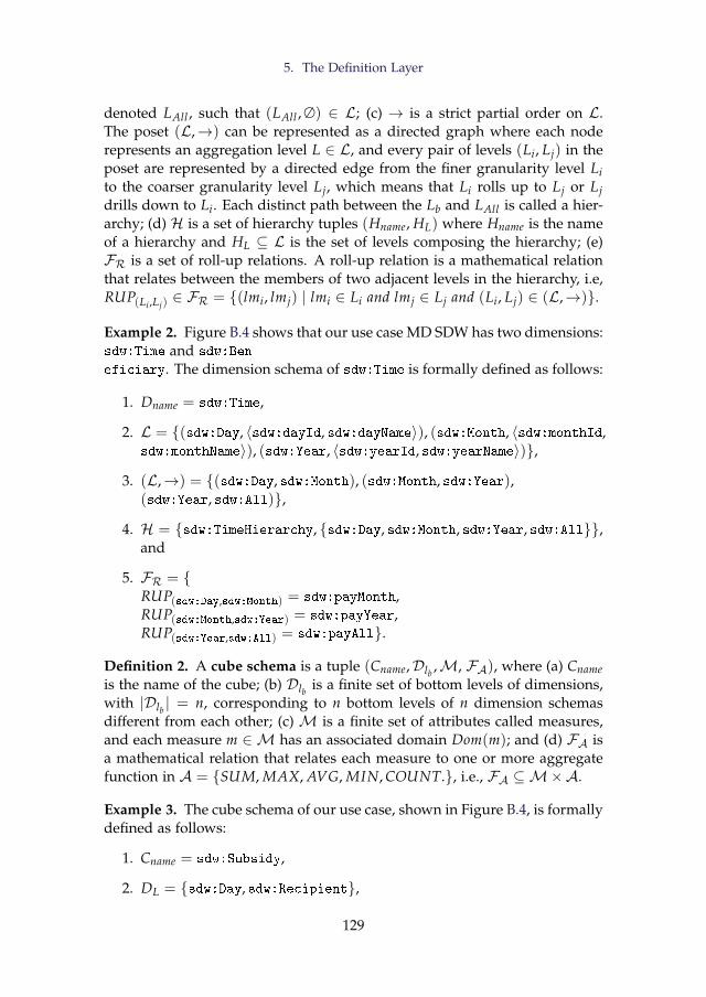
5. The Definition Layer
denoted LAll , such that (LAll , ∅) ∈ L; (c) → is a strict partial order on L.The poset (L,→) can be represented as a directed graph where each noderepresents an aggregation level L ∈ L, and every pair of levels (Li, Lj) in theposet are represented by a directed edge from the finer granularity level Lito the coarser granularity level Lj, which means that Li rolls up to Lj or Ljdrills down to Li. Each distinct path between the Lb and LAll is called a hier-archy; (d) H is a set of hierarchy tuples (Hname, HL) where Hname is the nameof a hierarchy and HL ⊆ L is the set of levels composing the hierarchy; (e)FR is a set of roll-up relations. A roll-up relation is a mathematical relationthat relates between the members of two adjacent levels in the hierarchy, i.e,RUP(Li ,Lj)
∈ FR = {(lmi, lmj) | lmi ∈ Li and lmj ∈ Lj and (Li, Lj) ∈ (L,→)}.
Example 2. Figure B.4 shows that our use case MD SDW has two dimensions:sdw:Time and sdw:Ben
eficiary. The dimension schema of sdw:Time is formally defined as follows:
1. Dname = sdw:Time,
2. L = {(sdw:Day, 〈sdw:dayId, sdw:dayName〉), (sdw:Month, 〈sdw:monthId,sdw:monthName〉), (sdw:Year, 〈sdw:yearId, sdw:yearName〉)},
3. (L,→) = {(sdw:Day, sdw:Month), (sdw:Month, sdw:Year),(sdw:Year, sdw:All)},
4. H = {sdw:TimeHierarchy, {sdw:Day, sdw:Month, sdw:Year, sdw:All}},and
5. FR = {RUP(sdw:Day,sdw:Month) = sdw:payMonth,RUP(sdw:Month,sdw:Year) = sdw:payYear,RUP(sdw:Year,sdw:All) = sdw:payAll}.
Definition 2. A cube schema is a tuple (Cname,Dlb ,M, FA), where (a) Cnameis the name of the cube; (b) Dlb is a finite set of bottom levels of dimensions,with |Dlb | = n, corresponding to n bottom levels of n dimension schemasdifferent from each other; (c) M is a finite set of attributes called measures,and each measure m ∈ M has an associated domain Dom(m); and (d) FA isa mathematical relation that relates each measure to one or more aggregatefunction in A = {SUM, MAX, AVG, MIN, COUNT.}, i.e., FA ⊆M×A.
Example 3. The cube schema of our use case, shown in Figure B.4, is formallydefined as follows:
1. Cname = sdw:Subsidy,
2. DL = {sdw:Day, sdw:Recipient},
129
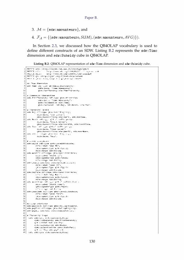
Paper B.
3. M = {sdw:amounteuro}, and
4. FA = {(sdw:amounteuro, SUM), (sdw:amounteuro, AVG)}).
In Section 2.3, we discussed how the QB4OLAP vocabulary is used todefine different constructs of an SDW. Listing B.2 represents the sdw:Time
dimension and sdw:Subsidy cube in QB4OLAP.
Listing B.2: QB4OLAP representation of sdw:Time dimension and sdw:Subsidy cube.
1 PREFIX sdw: <http :// extbi.lab.aau.dk/ontology/sdw/>
2 PREFIX rdf: http :// www.w3.org /1999/02/22 -rdf -syntax -ns#
3 PREFIX rdfs: http ://www.w3.org /2000/01/ rdf -schema#
4 PREFIX qb: <http :// purl.org/linked -data/cube#>
5 PREFIX qb4o: <http :// purl.org/qb4olap/cubes#>
67 ## Time Dimension
8 sdw:Time rdf:type qb:DimensionProperty;
9 rdfs:label "Time Dimension";
10 qb4o:hasHierarcy sdw:TimeHierarchy.
1112 # Dimension Hierarchies
13 sdw:TimeHierarchy rdf:type qb4o:Hierarchy;
14 rdfs:label "Time Hierarchy";
15 qb4o:inDimension sdw:Time;
16 qb4o:hasLevel sdw:Day , sdw:Month , sdw:Year.
1718 # Hierarchy levels
19 sdw:Day rdf:type qb4o:LevelProperty;
20 rdfs:label "Day Level";
21 qb4o:hasAttribute sdw:dayId , sdw:dayName.
22 sdw:Month rdf:type qb4o:LevelProperty;
23 rdfs:label "Month Level";
24 qb4o:hasAttribute sdw:monthId , sdw:monthName.
25 sdw:Year rdf:type qb4o:LevelProperty;
26 rdfs:label "Year Level";
27 qb4o:hasAttribute sdw:yearId , sdw:yearName.
28 sdw:All rdf:type qb4o:LevelProperty;
29 rdfs:label "ALL".
3031 # Level attributes
32 sdw:dayId rdf:type qb4o:LevelAttribute;
33 rdfs:label "day ID";
34 qb4o:updateType qb4o:Type2;
35 rdfs:range xsd:String.
36 sdw:monthId rdf:type qb4o:LevelAttribute;
37 rdfs:label "Month ID";
38 qb4o:updateType qb4o:Type2;
39 rdfs:range xsd:String.
40 sdw:yearId rdf:type qb4o:LevelAttribute;
41 rdfs:label "year ID";
42 qb4o:updateType qb4o:Type2;
43 rdfs:range xsd:String.
44 sdw:dayName rdf:type qb4o:LevelAttribute;
45 rdfs:label "day Name";
46 qb4o:updateType qb4o:Type1;
47 rdfs:range xsd:String.
48 sdw:monthName rdf:type qb4o:LevelAttribute;
49 rdfs:label "Month Name";
50 qb4o:updateType qb4o:Type1;
51 rdfs:range xsd:String.
52 sdw:yearName rdf:type qb4o:LevelAttribute;
53 rdfs:label "year Name";
54 qb4o:updateType qb4o:Type1;
55 rdfs:range xsd:String.
5657 #rollup relations
58 sdw:payMonth rdf:type qb4o:RollupProperty.
59 sdw:payYear rdf:type qb4o:RollupProperty.
60 sdw:payAll rdf:type qb4o:RollupProperty.
6162 # Hierarchy Steps
63 _:ht1 rdf:type qb4o:HierarchyStep;
64 qb4o:inHierarchy sdw:TimeHierarchy;
65 qb4o:childLevel sdw:Day;
66 qb4o:parentLevel sdw:Month;
67 qb4o:pcCardinality qb4o:OneToMany;
68 qb4o:rollup sdw:payMonth.
69 _:ht2 rdf:type qb4o:HierarchyStep;
130
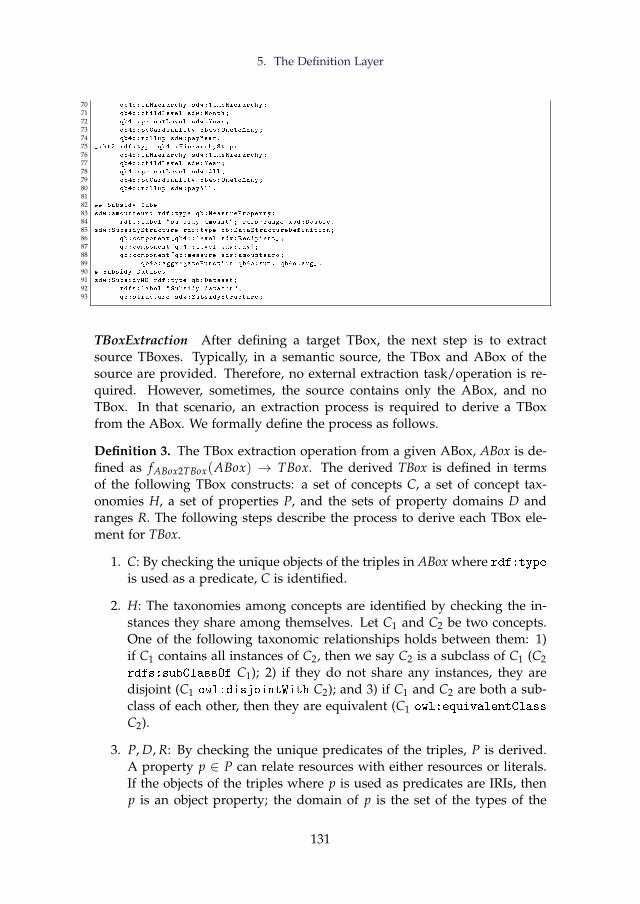
5. The Definition Layer
70 qb4o:inHierarchy sdw:TimeHierarchy;
71 qb4o:childLevel sdw:Month;
72 qb4o:parentLevel sdw:Year;
73 qb4o:pcCardinality qb4o:OneToMany;
74 qb4o:rollup sdw:payYear.
75 _:ht2 rdf:type qb4o:HierarchyStep;
76 qb4o:inHierarchy sdw:TimeHierarchy;
77 qb4o:childLevel sdw:Year;
78 qb4o:parentLevel sdw:All;
79 qb4o:pcCardinality qb4o:OneToMany;
80 qb4o:rollup sdw:payAll.
8182 ## Subsidy Cube
83 sdw:amounteuro rdf:type qb:MeasureProperty;
84 rdfs:label "subsidy amount"; rdfs:range xsd:Double.
85 sdw:SubsidyStructure rdf:type qb:DataStructureDefinition;
86 qb:component[qb4o:level sdw:Recipient ];
87 qb:component[qb4o:level sdw:Day];
88 qb:component[qb:measure sdw:amounteuro;
89 qb4o:aggregateFunction qb4o:sum , qb4o:avg].
90 # Subsidy Dataset
91 sdw:SubsidyMD rdf:type qb:Dataset;
92 rdfs:label "Subsidy dataset";
93 qb:structure sdw:SubsidyStructure;
TBoxExtraction After defining a target TBox, the next step is to extractsource TBoxes. Typically, in a semantic source, the TBox and ABox of thesource are provided. Therefore, no external extraction task/operation is re-quired. However, sometimes, the source contains only the ABox, and noTBox. In that scenario, an extraction process is required to derive a TBoxfrom the ABox. We formally define the process as follows.
Definition 3. The TBox extraction operation from a given ABox, ABox is de-fined as fABox2TBox(ABox) → TBox. The derived TBox is defined in termsof the following TBox constructs: a set of concepts C, a set of concept tax-onomies H, a set of properties P, and the sets of property domains D andranges R. The following steps describe the process to derive each TBox ele-ment for TBox.
1. C: By checking the unique objects of the triples in ABox where rdf:type
is used as a predicate, C is identified.
2. H: The taxonomies among concepts are identified by checking the in-stances they share among themselves. Let C1 and C2 be two concepts.One of the following taxonomic relationships holds between them: 1)if C1 contains all instances of C2, then we say C2 is a subclass of C1 (C2rdfs:subClassOf C1); 2) if they do not share any instances, they aredisjoint (C1 owl:disjointWith C2); and 3) if C1 and C2 are both a sub-class of each other, then they are equivalent (C1 owl:equivalentClass
C2).
3. P, D, R: By checking the unique predicates of the triples, P is derived.A property p ∈ P can relate resources with either resources or literals.If the objects of the triples where p is used as predicates are IRIs, thenp is an object property; the domain of p is the set of the types of the
131
Paper B.
subjects of those triples, and the range of p is the types of the objects ofthose triples. If the objects of the triples where p is used as predicatesare literals, then p is a datatype property; the domain of p is the set oftypes the subjects of those triples, and the range is the set of data typesof the literals.
SourceToTargetMapping Once the target and source TBoxes are defined, thenext task is to characterize the ETL flows at the Definition Layer by creatingsource-to-target mappings. Because of the heterogeneous nature of sourcedata, mappings among sources and the target should be done at the TBoxlevel. In principle, mappings are constructed between sources and the tar-get; however, since mappings can get very complicated, we allow to createa sequence of SourceToTargetMapping definitions whose subsequent input isgenerated by the preceding operation. The communication between theseoperations is by means of a materialized intermediate mapping definitionand its meant to facilitate the creation of very complex flows (i.e., mappings)between source and target.
A source-to-target mapping is constructed between a source and a tar-get TBox, and it consists of a set of concept-mappings. A concept-mappingdefines i) a relationship (equivalence, subsumption, supersumption, or join)between a source and the corresponding target concept, ii) which source in-stances are mapped (either all or a subset defined by a filter condition), iii)the rule to create the IRI for target concept instances, iv) the source and tar-get ABox locations, v) the common properties between two concepts if theirrelationship is join, vi) the sequence of ETL operations required to processthe concept-mapping, and vii) a set of property-mappings for each propertyhaving the target concept as a domain. A property-mapping defines how atarget property is mapped from either a source property or an expressionover properties. Definition 4 formally defines a source-to-target mapping.
Definition 4. Let TS and TT be a source TBox and a target TBox. We formallydefine a source-to-target mapping as a set of concept-mappings, whereineach concept-mapping is defined with a 10-tuple formalizing the elementsdiscussed above (i-vii):
SourceToTargetMapping(TS, TT) = {(cs, relation, ct, loccs , locct , mapIns,pmap, tiniri, pcom, op)}.
The semantics of each concept-mapping tuple is given below.
- cs ∈ C(TS) and eti ∈ C(TT) are a source and a target concept respec-tively, where C(T) defined in Equation B.1.
- relation ∈ {≡,v,w, ./} represents the relationship between the sourceand target concept. The relationship can be either equivalence (esi ≡ eti ),supersumption (esi w eti ), subsumption (esi v eti ), or join (esi ./ eti ). A
132
5. The Definition Layer
join relationship exists between two sources when there is a need topopulate a target element (a level, a (QB) dataset, or a concept) frommultiple sources. Since a concept-mapping represents a binary rela-tionship, to join n sources, an ETL process requires n− 1 join concept-mappings. A concept-mapping with a join relationship requires twosources (i.e., the concept-mapping source and target concepts) as inputand updates the target concept according to the join result. Thus, formulti-way joins, the output of a concept-mapping is a source concept ofthe next concept-mapping. Note that, a join relationship can be naturaljoin (./), right-outer join (./ ), or left-outer join ( ./).
- loccs and locct are the locations of source and target concept ABoxes.
- mapIns ∈ ({All} ∪ FilterCondition) indicates which instances of thesource concept to use to populate the target concept; it can either beall source instances or a subset of source instances defined by a filtercondition.
- pmap = {(pcs , pct)} is a set of property-mappings across the propertiesof cs and ct. pcs can be a property from property(cs) or an expres-sion over the elements of exp(property(cs) ∪ property(ct)) and pct is aproperty from property(ct). Here, property(c) returns the union of theset of properties which are connected with concept c either using therdfs:domain or qb4olap:inLevel properties, or the set of rollup prop-erties related to c. An expression allows to apply arithmetic operationsand/or some high-level functions for manipulating strings, data types,numbers, dates defined as standard SPARQL functions in [21] over theproperties.
- tiniri indicates how the unique IRIs of target instances are generated.The IRIs can be either the same as the source instances, or created usinga property of cs, or using an expression from exp(property(cs)), or inan incremental way.
- pcom = {(scomi, tcomi)|scomi ∈ (property(esi ), tcomi ∈ property(eti ))}is a set of common property pairs. In each pair, the first element is asource property and the second one is a target property. pcom is requiredwhen the relationship between the source and target concept is a join.
- op is an ETL operation or a sequence of ETL operations required toimplements the mapping element in the ABox level. When op is a se-quence of ETL operations, the location of the input ABox location forthe first operation in the sequence is loccs ; the subsequent operations inthe sequence take the output of their preceding operation as the inputABox. This generation of intermediate results is automatically handledby the automatic ETL generation process described in Section 7.
133
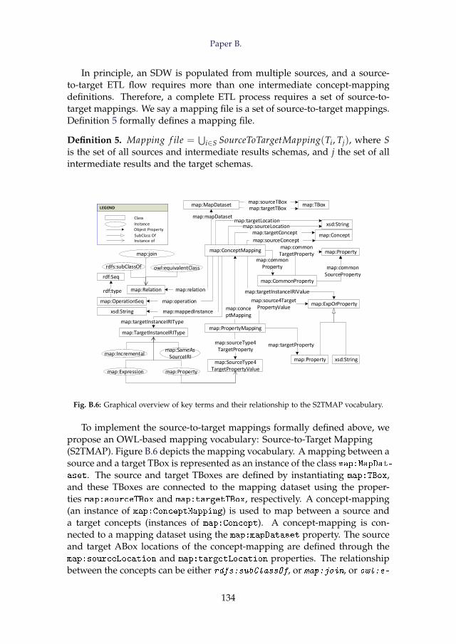
Paper B.
In principle, an SDW is populated from multiple sources, and a source-to-target ETL flow requires more than one intermediate concept-mappingdefinitions. Therefore, a complete ETL process requires a set of source-to-target mappings. We say a mapping file is a set of source-to-target mappings.Definition 5 formally defines a mapping file.
Definition 5. Mapping f ile =⋃
i∈S SourceToTargetMapping(Ti, Tj), where Sis the set of all sources and intermediate results schemas, and j the set of allintermediate results and the target schemas.
map:MapDataset
rdfs:subClassOf
map:ConceptMapping
map:PropertyMapping
map:TBox
xsd:String
map:Concept
map:Relation
xsd:String
map:TargetInstanceIRIType
map:Property
map:ExpOrProperty
owl:equivalentClass
map:join
map:Property
map:Incremental
map:Expression
map:SameAsSourceIRI
map:SourceType4TargetPropertyValue
map:sourceType4TargetProperty
map:source4TargetPropertyValue
map:targetInstanceIRIValue
map:mapDataset
map:OperationSeq
map:Property
map:targetInstanceIRIType
map:targetProperty
map:mappedInstance
map:operation
map:relation
LEGEND
Class
InstanceObject Property
SubClass OfInstance of
LEGEND
Class
InstanceObject Property
SubClass OfInstance of
map:conceptMapping
rdf:Seq
rdf:type
xsd:Stringmap:sourceLocationmap:targetLocation
map:targetTBoxmap:sourceTBox
map:targetConcept
map:sourceConcept
map:CommonProperty
map:commonSourceProperty
map:commonTargetProperty
map:commonProperty
Fig. B.6: Graphical overview of key terms and their relationship to the S2TMAP vocabulary.
To implement the source-to-target mappings formally defined above, wepropose an OWL-based mapping vocabulary: Source-to-Target Mapping(S2TMAP). Figure B.6 depicts the mapping vocabulary. A mapping between asource and a target TBox is represented as an instance of the class map:MapDat-aset. The source and target TBoxes are defined by instantiating map:TBox,and these TBoxes are connected to the mapping dataset using the proper-ties map:sourceTBox and map:targetTBox, respectively. A concept-mapping(an instance of map:ConceptMapping) is used to map between a source anda target concepts (instances of map:Concept). A concept-mapping is con-nected to a mapping dataset using the map:mapDataset property. The sourceand target ABox locations of the concept-mapping are defined through themap:sourceLocation and map:targetLocation properties. The relationshipbetween the concepts can be either rdfs:subClassOf, or map:join, or owl:e-
134
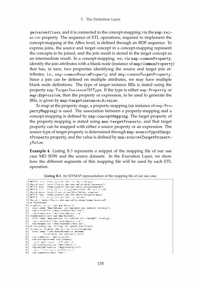
5. The Definition Layer
quivalentClass, and it is connected to the concept-mapping via the map:rel-ation property. The sequence of ETL operations, required to implement theconcept-mapping at the ABox level, is defined through an RDF sequence. Toexpress joins, the source and target concept in a concept-mapping representthe concepts to be joined, and the join result is stored in the target concept asan intermediate result. In a concept-mapping, we, via map:commonProperty,identify the join attributes with a blank node (instance of map:CommonProperty)that has, in turn, two properties identifying the source and target join at-tributes; i.e., map:commonSourceProperty and map:commonTargetProperty.Since a join can be defined on multiple attributes, we may have multipleblank node definitions. The type of target instance IRIs is stated using theproperty map:TargetInstanceIRIType. If the type is either map:Property ormap:Expression, then the property or expression, to be used to generate theIRIs, is given by map:targetInstanceIRIvalue.
To map at the property stage, a property-mapping (an instance of map:Pro-pertyMapping) is used. The association between a property-mapping and aconcept-mapping is defined by map:conceptMapping. The target property ofthe property-mapping is stated using map:targetProperty, and that targetproperty can be mapped with either a source property or an expression. Thesource type of target property is determined through map:sourceType4Targe-
tProperty property, and the value is defined by map:source4TargetPropert-
yValue.
Example 4. Listing B.3 represents a snippet of the mapping file of our usecase MD SDW and the source datasets. In the Execution Layer, we showhow the different segments of this mapping file will be used by each ETLoperation.
Listing B.3: An S2TMAP representation of the mapping file of our use case.
1 PREFIX onto: <http :// extbi.lab.aau.dk/ontology/>
2 PREFIX bus: <http :// extbi.lab.aau.dk/ontology/business/>
3 PREFIX sub: <http :// extbi.lab.aau.dk/ontology/subsidy/>
4 PREFIX rdf: <http :// www.w3.org /1999/02/22 -rdf -syntax -ns#>
5 PREFIX rdfs: <http ://www.w3.org /2000/01/ rdf -schema#>
6 PREFIX map: <http :// extbi.lab.aau.dk/ontology/s2tmap/>
7 PREFIX sdw: <http :// extbi.lab.aau.dk/sdw >
8 PREFIX : <http :// extbi.lab.aau.dk/ontology/s2map/example#>
9 ## MapDataset
10 :mapDataset1 rdf:type map:Dataset;
11 rdfs:label "Map -dataset for business and subsidy ontology";
12 map:sourceTBox "/map/businessTBox.ttl";
13 map:targetTBox "/map/subsidyTBox.ttl".
14 :mapDataset2 rdf:type map:Dataset;
15 rdfs:label "Map -dataset for subsidy and subsidyMD ontology";
16 map:sourceTBox "/map/subsidyTBox.ttl";
17 map:targetTBox "/map/subsidyMDTBox.ttl".
18 ## ConceptMapping: Joining Recipient and Company
19 :Recipient_Company rdf:type map:ConceptMapping;
20 rdfs:label "join -transformation between
21 bus:Company and sub:Recipient";
22 map:mapDataset :mapDataset1;
23 map:sourceConcept bus:Company;
24 map:targetConcept sub:Recipient;
25 map:sourceLocation "/map/dbd.nt";
26 map:targetLocation "/map/subsidy.nt";
27 map:relation map:rightOuterjoin;
28 map:mappedInstance "All";
135
Paper B.
29 map:targetInstanceIRIUniqueValueType map:SameAsSourceIRI;
30 map:operation _:opSeq;
31 map:commonProperty _:cp1 , _:cp2.
32 _:opSeq rdf:type rdf:Seq;
33 rdf:_1 map:joinTransformation.
34 _:cp1 map:sourceCommonProperty bus:ownerName;
35 map:targetCommonProperty sub:name.
36 _:cp2 map:sourceCommonProperty bus:officialAddress;
37 map:targetCommonProperty sub:address.
3839 #concept -mapping: Populating the sdw:Recipient level
40 :Recipient_RecipientMD rdf:type map:ConceptMapping;
41 rdfs:label "Level member generation";
42 map:mapDataset :mapDataset2;
43 map:sourceConcept sub:Recipient;
44 map:targetConcept sdw:Recipient;
45 map:sourceLocation "/map/subsidy.nt";
46 map:targetLocation "/map/sdw";
47 map:relation owl:equivalentClass;
48 map:mappedInstance "All";
49 map:targetInstanceIRIValueType map:Property;
50 map:targetInstanceIRIValue sub:recipientID;
51 map:operation _:opSeq1.
52 _:opSeq1 rdf:type rdf:Seq;
53 rdf:_1 map:LevelMemberGenerator;
54 rdf:_2 map:Loader.
55 #concept -mapping: Populating the cube dataset
56 :Subsidy_SubsidyMD rdf:type map:ConceptMapping;
57 rdfs:label "Observation generation";
58 map:mapDataset :mapDataset2;
59 map:sourceConcept sub:Subsidy;
60 map:targetConcept sdw:SubsidyMD;
61 map:sourceLocation "/map/subsidy.nt";
62 map:targetLocation "/map/sdw";
63 map:relation owl:equivalentClass;
64 map:mappedInstance "All";
65 map:targetInstanceIRIUniqueValueType map:Incremental;
66 map:operation _:opSeq2.
67 _:opSeq2 rdf:type rdf:Seq;
68 rdf:_1 map:GraphExtractor;
69 rdf:_2 map:TransformationOnLiteral;
70 rdf:_3 map:ObservationGenerator;
71 rdf:_4 map:Loader.
72 ## property -mapping under :Recipient_Company
73 :companyID_companyID rdf:type map:PropertyMapping;
74 rdfs:label "property -mapping for companyID";
75 map:conceptMapping :Recipient_Company;
76 map:targetProperty sub:companyId;
77 map:sourceType4TargetPropertyValue map:Property;
78 map:source4TargetPropertyValue bus:companyId.
79 :businessType_businessType rdf:type map:PropertyMapping;
80 rdfs:label "property -mapping for business type";
81 map:conceptMapping :Recipient_Company;
82 map:targetProperty sub:businessType;
83 map:sourceType4TargetPropertyValue map:Property;
84 map:source4TargetPropertyValue bus:hasFormat.
85 :address_city rdf:type map:PropertyMapping;
86 rdfs:label "property -mapping for city";
87 map:conceptMapping :Recipient_Company;
88 map:targetProperty sub:cityId;
89 map:sourceType4TargetPropertyValue map:Expression;
90 map:source4TargetPropertyValue STRAFTER(sub:address ,",").
91 :name_name rdf:type map:PropertyMapping;
92 rdfs:label "property -mapping for name";
93 map:conceptMapping :Recipient_Company;
94 map:targetProperty sub:name;
95 map:sourceType4TargetPropertyValue map:Property;
96 map:source4TargetPropertyValue sub:name.
97 # property -mappings under :Recipient_RecipientMD
98 :companyId_company rdf:type map:PropertyMapping;
99 rdfs:label "property -mapping for companyId";
100 map:conceptMapping :Recipient_RecipientMD;
101 map:targetProperty sdw:hasCompany;
102 map:sourceType4TargetPropertyValue map:Property;
103 map:source4TargetPropertyValue sub:companyId;
104 :cityId_city rdf:type map:PropertyMapping;
105 rdfs:label "property -mapping for cityId";
106 map:conceptMapping :Recipient_RecipientMD;
107 map:targetProperty sdw:inCity;
108 map:sourceType4TargetPropertyValue map:Property;
109 map:source4TargetPropertyValue sub:city;
110 :name_name rdf:type map:PropertyMapping;
111 rdfs:label "property -mapping for name";
112 map:conceptMapping :Recipient_RecipientMD;
113 map:targetProperty sdw:name;
136
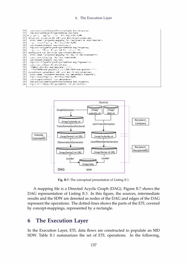
6. The Execution Layer
114 map:sourceType4TargetPropertyValue map:Property;
115 map:source4TargetPropertyValue sub:name
116 # property -mappings under :Subsidy_SubsidyMD
117 :Recipient_recipientId rdf:type map:PropertyMapping;
118 rdfs:label "property -mapping for recipient in sdw:Subsidy";
119 map:conceptMapping :Subsidy_SubsidyMD;
120 map:targetProperty sdw:Recipient;
121 map:sourceType4TargetPropertyValue map:Property;
122 map:source4TargetPropertyValue sub:paidTo.
123 :hasPayDate_Day rdf:type map:PropertyMapping;
124 rdfs:label "property -mapping for Day of sdw:SubsidyMD";
125 map:conceptMapping :Subsidy_SubsidyMD;
126 map:targetProperty sdw:Day;
127 map:sourceType4TargetPropertyValue map:Expression;
128 map:source4TargetPropertyValue
129 "CONCAT(STR(DAY(sub:payDate)),"/",
130 STR(MONTH(sub:payDate)),"/",STR(YEAR(sub:payDate )))".
131 :amountEuro_amountEuro rdf:type map:PropertyMapping;
132 rdfs:label "property -mapping for amountEuro measure";
133 map:conceptMapping :Subsidy_SubsidyMD;
134 map:targetProperty sdw:amountEuro;
135 map:sourceType4TargetPropertyValue map:Property;
136 map:source4TargetPropertyValue sub:amountEuro.
:Subsidy_SubsidyMD
/map/subsidy.nt
/map/dbd.nt
/map/subsidy.nt
/map/sdw
Sources
SDW
/map/temp.nt (IR)
JoinTransformation
LevelMemberGenerator
Loader
/map/subsidy.nt
/map/temp1.nt (IR)
/map/temp2.nt (IR)
TransformationOnLiteral
ObservationGenerator
Loader
GraphExtractor
:Recipient_Company
:Recipient_RecipientMD
DAG
Fig. B.7: The conceptual presentation of Listing B.3.
A mapping file is a Directed Acyclic Graph (DAG). Figure B.7 shows theDAG representation of Listing B.3. In this figure, the sources, intermediateresults and the SDW are denoted as nodes of the DAG and edges of the DAGrepresent the operations. The dotted-lines shows the parts of the ETL coveredby concept-mappings, represented by a rectangle.
6 The Execution Layer
In the Execution Layer, ETL data flows are constructed to populate an MDSDW. Table B.1 summarizes the set of ETL operations. In the following,
137
Paper B.
we present an overview of each operation category-wise. Here, we give theintuitions of the ETL operations in terms of definitions and examples. Toreduce the complexity and length of the paper, we place the semantics of theETL operations in Section A. In this section, we present the signature of eachoperation. That is, the main inputs required to execute the operation and theproduced outcome. As an ETL data flow is a sequence of operations and anoperation in the sequence communicates with its preceding and subsequentoperations by means of materialized intermediate results, all the operationspresented here have side-effects.
Developers can use either of the two following options: (i) The recom-mended option is that given a TBox construct aConstruct (a concept, a level, ora QB dataset) and a mapping file aMappings generated in the Definition Layer,the automatic ETL execution flow generation process will automatically ex-tract the values for operations’ parameters from aMappings (see Section 7 fora detailed explanation of the automatic ETL execution flow generation pro-cess). (ii) They can manually set input parameters at the operation level. Inthis section, we follow the following order to present each operation: 1) wefirst give a high-level definition of the operation; 2) then, we define how theautomatic ETL execution flow generation process parameterizes the opera-tion from the mapping file, and 3) finally, we present an example showinghow developers can manually parameterize the operation. When introducingthe operations and referring to its automatic parametrization, we will refer toaMappings and aConstruct as defined here. Note that each operation is boundto exactly one concept-mapping at a time in the mapping file (discussed inSection 7).
6.1 Extraction Operations
Extraction is process of data retrieval from the sources. Here, we introducetwo extraction operations for semantic sources: (i) GraphExtractor - to for-m/extract an RDF graph from a semantic source and (ii) TBoxExtraction - toderive a TBox from a semantic source as described in Section 5. As such,TBoxExtraction is the only operation in the Execution Layer generating meta-data stored in the Mediatory Constructs (see Figure B.5).
GraphExtractor(Q, G, outputPattern, tABox) Since the data integration pro-cess proposed in this paper uses RDF as the canonical model, we extract/-generate RDF triples from the sources with this operation. GraphExtractor isfunctionally equivalent to SPARQL CONSTRUCT queries [34].
If the ETL execution flow is generated automatically, the automatic ETLexecution flow generation process first identifies the concept-mapping cm
from aMappings where aConstruct appears (i.e., in aMapping, cmmap:targetConcept−−−−−−−−−−→
138
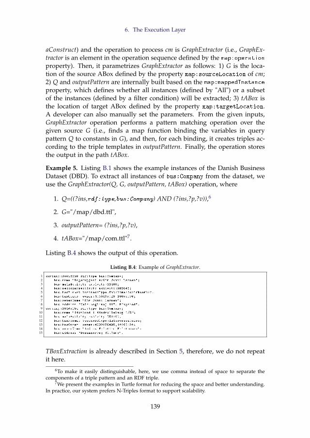
6. The Execution Layer
aConstruct) and the operation to process cm is GraphExtractor (i.e., GraphEx-tractor is an element in the operation sequence defined by the map:operation
property). Then, it parametrizes GraphExtractor as follows: 1) G is the loca-tion of the source ABox defined by the property map:sourceLocation of cm;2) Q and outputPattern are internally built based on the map:mappedInstance
property, which defines whether all instances (defined by "All") or a subsetof the instances (defined by a filter condition) will be extracted; 3) tABox isthe location of target ABox defined by the property map:targetLocation.A developer can also manually set the parameters. From the given inputs,GraphExtractor operation performs a pattern matching operation over thegiven source G (i.e., finds a map function binding the variables in querypattern Q to constants in G), and then, for each binding, it creates triples ac-cording to the triple templates in outputPattern. Finally, the operation storesthe output in the path tABox.
Example 5. Listing B.1 shows the example instances of the Danish BusinessDataset (DBD). To extract all instances of bus:Company from the dataset, weuse the GraphExtractor(Q, G, outputPattern, tABox) operation, where
1. Q=((?ins,rdf:type,bus:Company) AND (?ins,?p,?v)),6
2. G="/map/dbd.ttl",
3. outputPattern= (?ins,?p,?v),
4. tABox="/map/com.ttl"7.
Listing B.4 shows the output of this operation.
Listing B.4: Example of GraphExtractor.
1 company :10058996 rdf:type bus:Company;
2 bus:name "Regerupgard v/Kim Jonni Larsen";
3 bus:mainActivity activity :11100;
4 bus:secondaryActivity activity :682040;
5 bus:hasFormat businessType:Enkeltmandsvirksomhed:
6 bus:hasOwner owner :4000175029 _10058996;
7 bus:ownerName "Kim Jonni Larsen";
8 bus:address "Valsomaglevej 117, Ringsted".
9 company :10165164 rdf:type bus:Company;
10 bus:name "Idomlund 1 Vindmollelaug I/S";
11 bus:mainActivity activity :351100;
12 bus:hasFormat businessType:Interessentskab;
13 bus:hasOwner owner :4000170495 _10165164;
14 bus:ownerName "Anders Kristian Kristensen";
15 bus:address "Donskaervej 31,Vemb".
TBoxExtraction is already described in Section 5, therefore, we do not repeatit here.
6To make it easily distinguishable, here, we use comma instead of space to separate thecomponents of a triple pattern and an RDF triple.
7We present the examples in Turtle format for reducing the space and better understanding.In practice, our system prefers N-Triples format to support scalability.
139
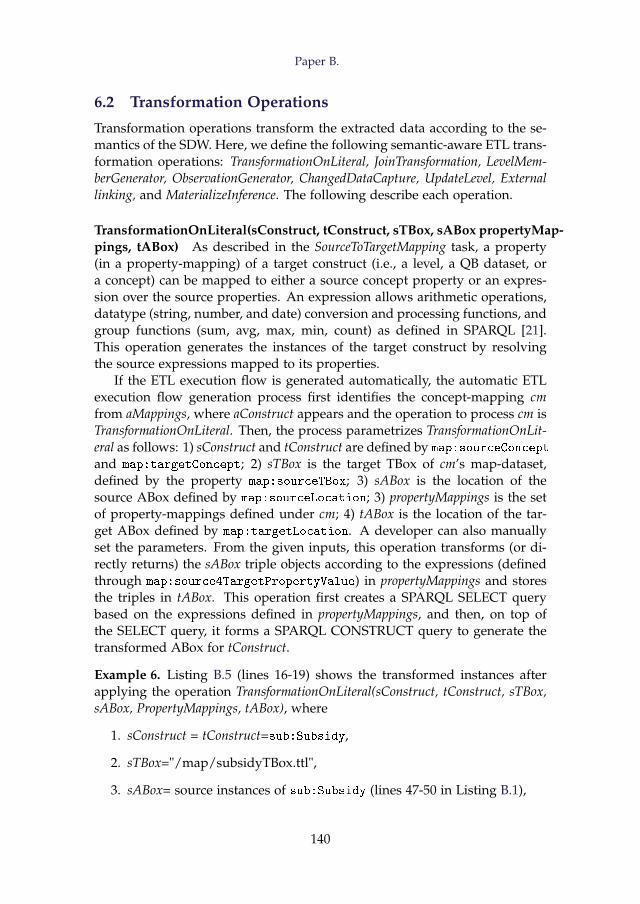
Paper B.
6.2 Transformation Operations
Transformation operations transform the extracted data according to the se-mantics of the SDW. Here, we define the following semantic-aware ETL trans-formation operations: TransformationOnLiteral, JoinTransformation, LevelMem-berGenerator, ObservationGenerator, ChangedDataCapture, UpdateLevel, Externallinking, and MaterializeInference. The following describe each operation.
TransformationOnLiteral(sConstruct, tConstruct, sTBox, sABox propertyMap-pings, tABox) As described in the SourceToTargetMapping task, a property(in a property-mapping) of a target construct (i.e., a level, a QB dataset, ora concept) can be mapped to either a source concept property or an expres-sion over the source properties. An expression allows arithmetic operations,datatype (string, number, and date) conversion and processing functions, andgroup functions (sum, avg, max, min, count) as defined in SPARQL [21].This operation generates the instances of the target construct by resolvingthe source expressions mapped to its properties.
If the ETL execution flow is generated automatically, the automatic ETLexecution flow generation process first identifies the concept-mapping cmfrom aMappings, where aConstruct appears and the operation to process cm isTransformationOnLiteral. Then, the process parametrizes TransformationOnLit-eral as follows: 1) sConstruct and tConstruct are defined by map:sourceConcept
and map:targetConcept; 2) sTBox is the target TBox of cm’s map-dataset,defined by the property map:sourceTBox; 3) sABox is the location of thesource ABox defined by map:sourceLocation; 3) propertyMappings is the setof property-mappings defined under cm; 4) tABox is the location of the tar-get ABox defined by map:targetLocation. A developer can also manuallyset the parameters. From the given inputs, this operation transforms (or di-rectly returns) the sABox triple objects according to the expressions (definedthrough map:source4TargetPropertyValue) in propertyMappings and storesthe triples in tABox. This operation first creates a SPARQL SELECT querybased on the expressions defined in propertyMappings, and then, on top ofthe SELECT query, it forms a SPARQL CONSTRUCT query to generate thetransformed ABox for tConstruct.
Example 6. Listing B.5 (lines 16-19) shows the transformed instances afterapplying the operation TransformationOnLiteral(sConstruct, tConstruct, sTBox,sABox, PropertyMappings, tABox), where
1. sConstruct = tConstruct=sub:Subsidy,
2. sTBox="/map/subsidyTBox.ttl",
3. sABox= source instances of sub:Subsidy (lines 47-50 in Listing B.1),
140
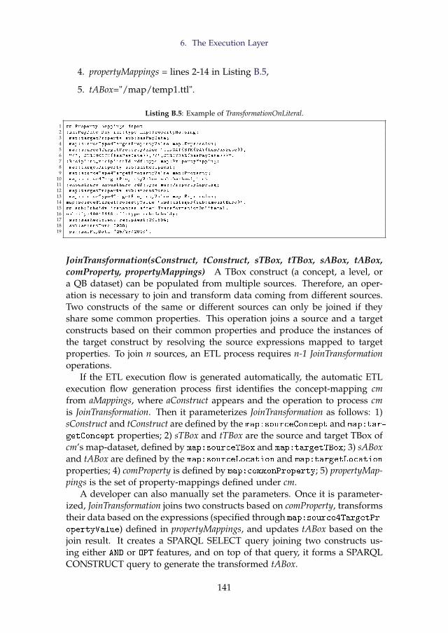
6. The Execution Layer
4. propertyMappings = lines 2-14 in Listing B.5,
5. tABox="/map/temp1.ttl".
Listing B.5: Example of TransformationOnLiteral.
1 ## Property -mappings input
2 :hasPayDate_Day rdf:type map:PropertyMapping;
3 map:targetProperty sub:hasPayDate;
4 map:sourceType4TargetPropertyValue map:Expression;
5 map:source4TargetPropertyValue "CONCAT(STR(DAY(hasPayDate )),
6 "/", STR(MONTH(hasPayDate )),"/",STR(YEAR(hasPayDate )))".
7 :Recipient_recipientId rdf:type map:PropertyMapping;
8 map:targetProperty sub:hasRecipient;
9 map:sourceType4TargetPropertyValue map:Property;
10 map:source4TargetPropertyValue sub:hasRecipient.
11 :amountEuro_amountEuro rdf:type map:PropertyMapping;
12 map:targetProperty sub:amountEuro;
13 map:sourceType4TargetPropertyValue map:Expression;
14 map:source4TargetPropertyValue "xsd:integer(sub:amountEuro)".
15 ## sub:Subsidy instances after TransformationOnLiteral.
16 subsidy :10615413 rdf:type sub:Subsidy;
17 sub:hasRecipient recipient :291894;
18 sub:amountEuro 8928;
19 sub:hasPayData "25/25/2010".
JoinTransformation(sConstruct, tConstruct, sTBox, tTBox, sABox, tABox,comProperty, propertyMappings) A TBox construct (a concept, a level, ora QB dataset) can be populated from multiple sources. Therefore, an oper-ation is necessary to join and transform data coming from different sources.Two constructs of the same or different sources can only be joined if theyshare some common properties. This operation joins a source and a targetconstructs based on their common properties and produce the instances ofthe target construct by resolving the source expressions mapped to targetproperties. To join n sources, an ETL process requires n-1 JoinTransformationoperations.
If the ETL execution flow is generated automatically, the automatic ETLexecution flow generation process first identifies the concept-mapping cmfrom aMappings, where aConstruct appears and the operation to process cmis JoinTransformation. Then it parameterizes JoinTransformation as follows: 1)sConstruct and tConstruct are defined by the map:sourceConcept and map:tar-
getConcept properties; 2) sTBox and tTBox are the source and target TBox ofcm’s map-dataset, defined by map:sourceTBox and map:targetTBox; 3) sABoxand tABox are defined by the map:sourceLocation and map:targetLocation
properties; 4) comProperty is defined by map:commonProperty; 5) propertyMap-pings is the set of property-mappings defined under cm.
A developer can also manually set the parameters. Once it is parameter-ized, JoinTransformation joins two constructs based on comProperty, transformstheir data based on the expressions (specified through map:source4TargetPr-
opertyValue) defined in propertyMappings, and updates tABox based on thejoin result. It creates a SPARQL SELECT query joining two constructs us-ing either AND or OPT features, and on top of that query, it forms a SPARQLCONSTRUCT query to generate the transformed tABox.
141
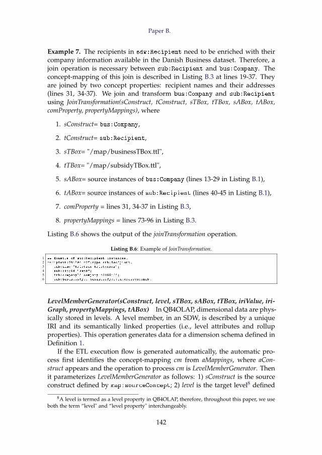
Paper B.
Example 7. The recipients in sdw:Recipient need to be enriched with theircompany information available in the Danish Business dataset. Therefore, ajoin operation is necessary between sub:Recipient and bus:Company. Theconcept-mapping of this join is described in Listing B.3 at lines 19-37. Theyare joined by two concept properties: recipient names and their addresses(lines 31, 34-37). We join and transform bus:Company and sub:Recipient
using JoinTransformation(sConstruct, tConstruct, sTBox, tTBox, sABox, tABox,comProperty, propertyMappings), where
1. sConstruct= bus:Company,
2. tConstruct= sub:Recipient,
3. sTBox= "/map/businessTBox.ttl",
4. tTBox= "/map/subsidyTBox.ttl",
5. sABox= source instances of bus:Company (lines 13-29 in Listing B.1),
6. tABox= source instances of sub:Recipient (lines 40-45 in Listing B.1),
7. comProperty = lines 31, 34-37 in Listing B.3,
8. propertyMappings = lines 73-96 in Listing B.3.
Listing B.6 shows the output of the joinTransformation operation.
Listing B.6: Example of JoinTransformation.
1 ## Example of sub:Recipient instances.
2 recipient :291894 rdf:type sub:Recipient;
3 sub:name "Kristian Kristensen";
4 sub:cityId "Vemb";
5 sub:companyId company :10165164;
6 sub:businessType businessType:Interessentskab.
LevelMemberGenerator(sConstruct, level, sTBox, sABox, tTBox, iriValue, iri-Graph, propertyMappings, tABox) In QB4OLAP, dimensional data are phys-ically stored in levels. A level member, in an SDW, is described by a uniqueIRI and its semantically linked properties (i.e., level attributes and rollupproperties). This operation generates data for a dimension schema defined inDefinition 1.
If the ETL execution flow is generated automatically, the automatic pro-cess first identifies the concept-mapping cm from aMappings, where aCon-struct appears and the operation to process cm is LevelMemberGenerator. Thenit parameterizes LevelMemberGenerator as follows: 1) sConstruct is the sourceconstruct defined by map:sourceConcept; 2) level is the target level8 defined
8A level is termed as a level property in QB4OLAP, therefore, throughout this paper, we useboth the term “level" and “level property" interchangeably.
142
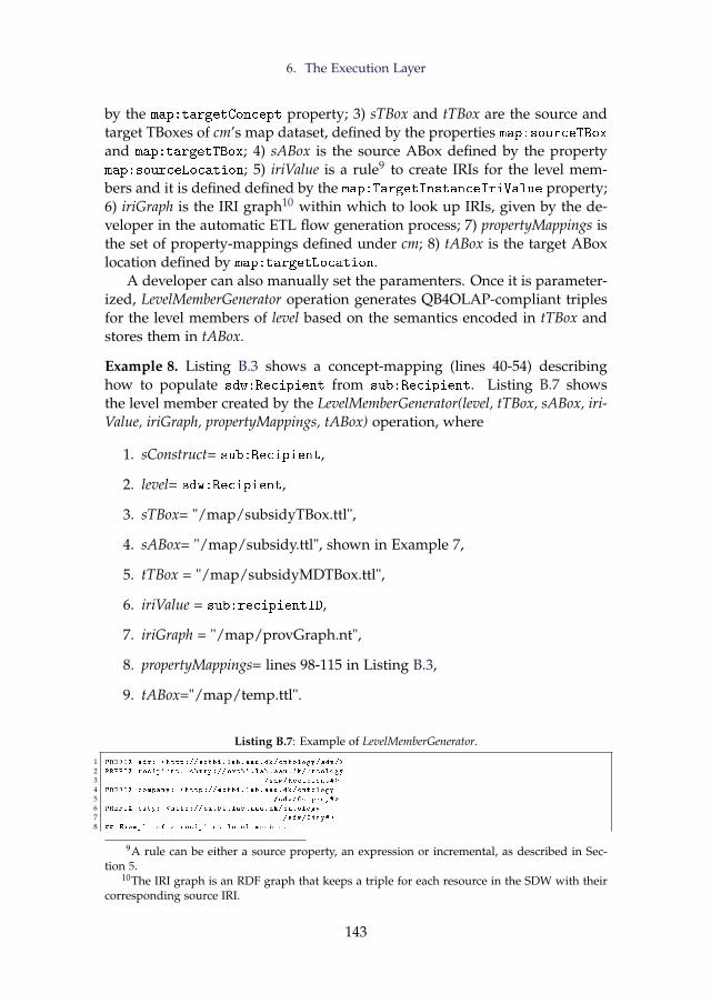
6. The Execution Layer
by the map:targetConcept property; 3) sTBox and tTBox are the source andtarget TBoxes of cm’s map dataset, defined by the properties map:sourceTBoxand map:targetTBox; 4) sABox is the source ABox defined by the propertymap:sourceLocation; 5) iriValue is a rule9 to create IRIs for the level mem-bers and it is defined defined by the map:TargetInstanceIriValue property;6) iriGraph is the IRI graph10 within which to look up IRIs, given by the de-veloper in the automatic ETL flow generation process; 7) propertyMappings isthe set of property-mappings defined under cm; 8) tABox is the target ABoxlocation defined by map:targetLocation.
A developer can also manually set the paramenters. Once it is parameter-ized, LevelMemberGenerator operation generates QB4OLAP-compliant triplesfor the level members of level based on the semantics encoded in tTBox andstores them in tABox.
Example 8. Listing B.3 shows a concept-mapping (lines 40-54) describinghow to populate sdw:Recipient from sub:Recipient. Listing B.7 showsthe level member created by the LevelMemberGenerator(level, tTBox, sABox, iri-Value, iriGraph, propertyMappings, tABox) operation, where
1. sConstruct= sub:Recipient,
2. level= sdw:Recipient,
3. sTBox= "/map/subsidyTBox.ttl",
4. sABox= "/map/subsidy.ttl", shown in Example 7,
5. tTBox = "/map/subsidyMDTBox.ttl",
6. iriValue = sub:recipientID,
7. iriGraph = "/map/provGraph.nt",
8. propertyMappings= lines 98-115 in Listing B.3,
9. tABox="/map/temp.ttl".
Listing B.7: Example of LevelMemberGenerator.
1 PREFIX sdw: <http :// extbi.lab.aau.dk/ontology/sdw/>
2 PREFIX recipient: <http :// extbi.lab.aau.dk/ontology
3 /sdw/Recipient#>
4 PREFIX company: <http :// extbi.lab.aau.dk/ontology
5 /sdw/Company#>
6 PREFIX city: <http :// extbi.lab.aau.dk/ontology
7 /sdw/City#>
8 ## Example of a recipient level member.
9A rule can be either a source property, an expression or incremental, as described in Sec-tion 5.
10The IRI graph is an RDF graph that keeps a triple for each resource in the SDW with theircorresponding source IRI.
143
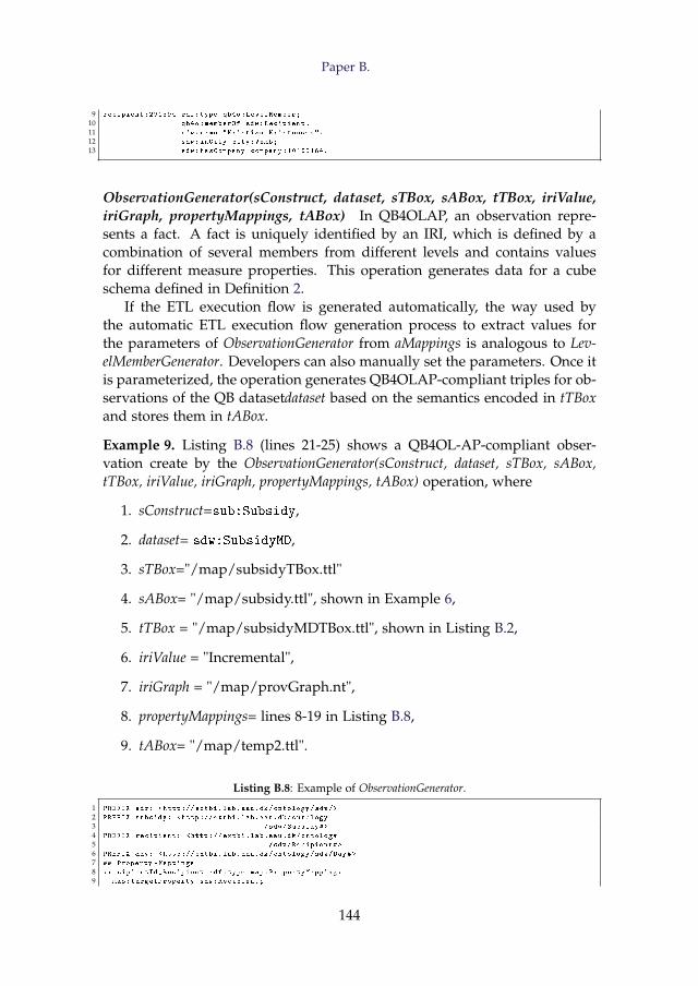
Paper B.
9 recipient :291894 rdf:type qb4o:LevelMember;
10 qb4o:memberOf sdw:Recipient.
11 sdw:name "Kristian Kristensen";
12 sdw:inCity city:Vemb;
13 sdw:hasCompany company :10165164.
ObservationGenerator(sConstruct, dataset, sTBox, sABox, tTBox, iriValue,iriGraph, propertyMappings, tABox) In QB4OLAP, an observation repre-sents a fact. A fact is uniquely identified by an IRI, which is defined by acombination of several members from different levels and contains valuesfor different measure properties. This operation generates data for a cubeschema defined in Definition 2.
If the ETL execution flow is generated automatically, the way used bythe automatic ETL execution flow generation process to extract values forthe parameters of ObservationGenerator from aMappings is analogous to Lev-elMemberGenerator. Developers can also manually set the parameters. Once itis parameterized, the operation generates QB4OLAP-compliant triples for ob-servations of the QB datasetdataset based on the semantics encoded in tTBoxand stores them in tABox.
Example 9. Listing B.8 (lines 21-25) shows a QB4OL-AP-compliant obser-vation create by the ObservationGenerator(sConstruct, dataset, sTBox, sABox,tTBox, iriValue, iriGraph, propertyMappings, tABox) operation, where
1. sConstruct=sub:Subsidy,
2. dataset= sdw:SubsidyMD,
3. sTBox="/map/subsidyTBox.ttl"
4. sABox= "/map/subsidy.ttl", shown in Example 6,
5. tTBox = "/map/subsidyMDTBox.ttl", shown in Listing B.2,
6. iriValue = "Incremental",
7. iriGraph = "/map/provGraph.nt",
8. propertyMappings= lines 8-19 in Listing B.8,
9. tABox= "/map/temp2.ttl".
Listing B.8: Example of ObservationGenerator.
1 PREFIX sdw: <http :// extbi.lab.aau.dk/ontology/sdw/>
2 PREFIX subsidy: <http :// extbi.lab.aau.dk/ontology
3 /sdw/Subsidy#>
4 PREFIX recipient: <http :// extbi.lab.aau.dk/ontology
5 /sdw/Recipient#>
6 PREFIX day: <http :// extbi.lab.aau.dk/ontology/sdw/Day#>
7 ## Property -Mappings
8 :recipientId_Recipient rdf:type map:PropertyMapping;
9 map:targetProperty sdw:Recipient;
144
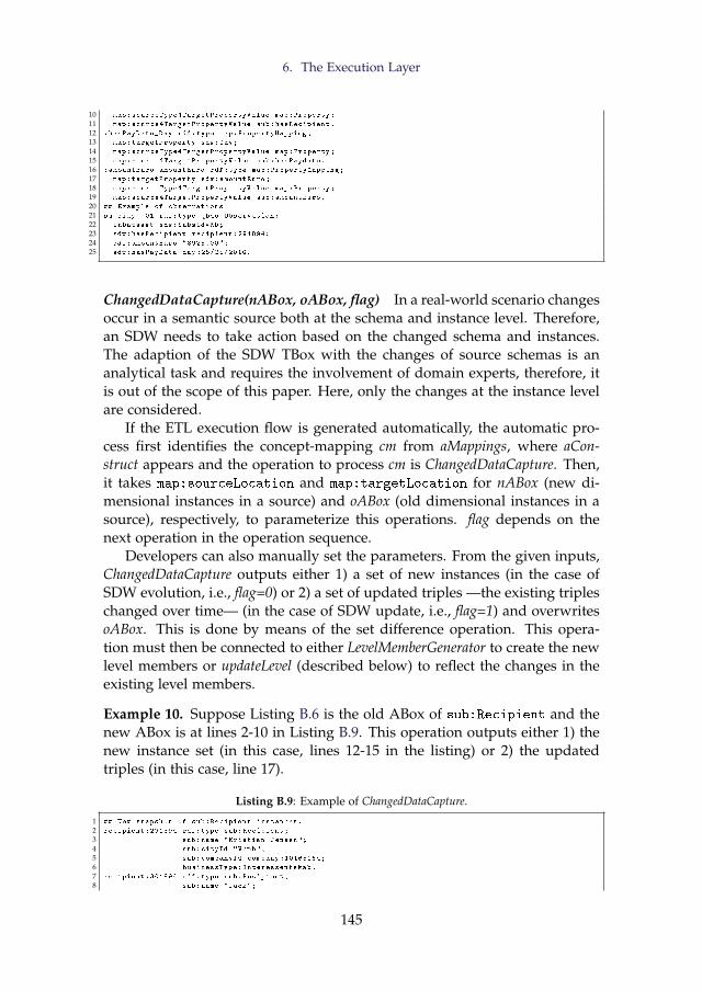
6. The Execution Layer
10 map:sourceType4TargetPropertyValue map:Property;
11 map:source4TargetPropertyValue sub:hasRecipient.
12 :hasPayDate_Day rdf:type map:PropertyMapping;
13 map:targetProperty sdw:Day;
14 map:sourceType4TargetPropertyValue map:Property;
15 map:source4TargetPropertyValue sub:hasPaydate.
16 :amountEuro_amountEuro rdf:type map:PropertyMapping;
17 map:targetProperty sdw:amountEuro;
18 map:sourceType4TargetPropertyValue map:Property;
19 map:source4TargetPropertyValue sub:amountEuro.
20 ## Example of observations
21 subsidy:_01 rdf:type qb4o:Observation;
22 inDataset sdw:SubsidyMD;
23 sdw:hasRecipient recipient :291894;
24 sdw:amountEuro "8928.00";
25 sdw:hasPayData day :25/25/2010.
ChangedDataCapture(nABox, oABox, flag) In a real-world scenario changesoccur in a semantic source both at the schema and instance level. Therefore,an SDW needs to take action based on the changed schema and instances.The adaption of the SDW TBox with the changes of source schemas is ananalytical task and requires the involvement of domain experts, therefore, itis out of the scope of this paper. Here, only the changes at the instance levelare considered.
If the ETL execution flow is generated automatically, the automatic pro-cess first identifies the concept-mapping cm from aMappings, where aCon-struct appears and the operation to process cm is ChangedDataCapture. Then,it takes map:sourceLocation and map:targetLocation for nABox (new di-mensional instances in a source) and oABox (old dimensional instances in asource), respectively, to parameterize this operations. flag depends on thenext operation in the operation sequence.
Developers can also manually set the parameters. From the given inputs,ChangedDataCapture outputs either 1) a set of new instances (in the case ofSDW evolution, i.e., flag=0) or 2) a set of updated triples —the existing tripleschanged over time— (in the case of SDW update, i.e., flag=1) and overwritesoABox. This is done by means of the set difference operation. This opera-tion must then be connected to either LevelMemberGenerator to create the newlevel members or updateLevel (described below) to reflect the changes in theexisting level members.
Example 10. Suppose Listing B.6 is the old ABox of sub:Recipient and thenew ABox is at lines 2-10 in Listing B.9. This operation outputs either 1) thenew instance set (in this case, lines 12-15 in the listing) or 2) the updatedtriples (in this case, line 17).
Listing B.9: Example of ChangedDataCapture.
1 ## New snapshot of sub:Recipient instances.
2 recipient :291894 rdf:type sub:Recipient;
3 sub:name "Kristian Jensen";
4 sub:cityId "Vemb";
5 sub:companyId company :10165164;
6 businessType:Interessentskab.
7 recipient :301894 rdf:type sub:Recipient;
8 sub:name "Jack";
145
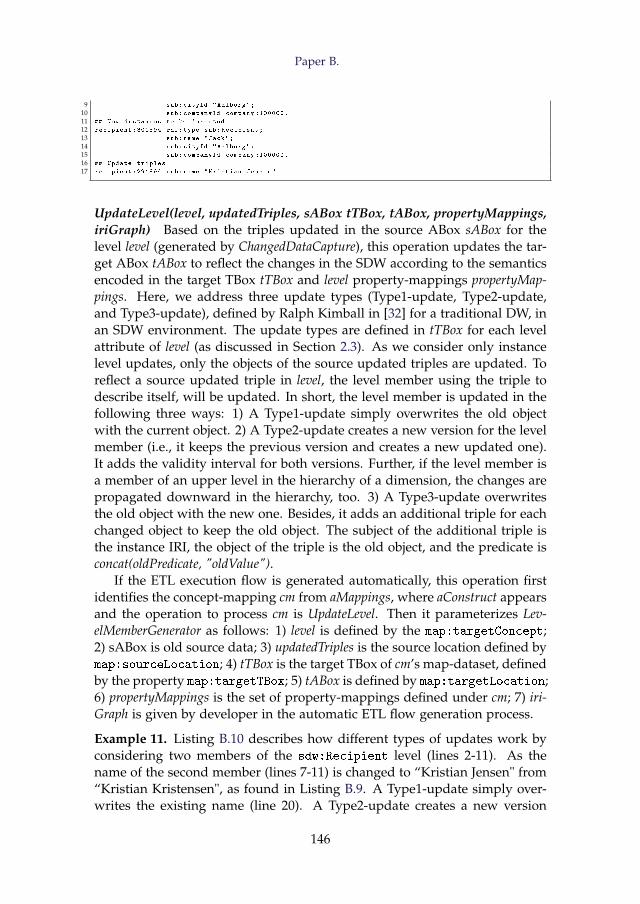
Paper B.
9 sub:cityId "Aalborg";
10 sub:companyId company :100000.
11 ## New instances to be inserted
12 recipient :301894 rdf:type sub:Recipient;
13 sub:name "Jack";
14 sub:cityId "Aalborg";
15 sub:companyId company :100000.
16 ## Update triples
17 recipient :291894 sub:name "Kristian Jensen".
UpdateLevel(level, updatedTriples, sABox tTBox, tABox, propertyMappings,iriGraph) Based on the triples updated in the source ABox sABox for thelevel level (generated by ChangedDataCapture), this operation updates the tar-get ABox tABox to reflect the changes in the SDW according to the semanticsencoded in the target TBox tTBox and level property-mappings propertyMap-pings. Here, we address three update types (Type1-update, Type2-update,and Type3-update), defined by Ralph Kimball in [32] for a traditional DW, inan SDW environment. The update types are defined in tTBox for each levelattribute of level (as discussed in Section 2.3). As we consider only instancelevel updates, only the objects of the source updated triples are updated. Toreflect a source updated triple in level, the level member using the triple todescribe itself, will be updated. In short, the level member is updated in thefollowing three ways: 1) A Type1-update simply overwrites the old objectwith the current object. 2) A Type2-update creates a new version for the levelmember (i.e., it keeps the previous version and creates a new updated one).It adds the validity interval for both versions. Further, if the level member isa member of an upper level in the hierarchy of a dimension, the changes arepropagated downward in the hierarchy, too. 3) A Type3-update overwritesthe old object with the new one. Besides, it adds an additional triple for eachchanged object to keep the old object. The subject of the additional triple isthe instance IRI, the object of the triple is the old object, and the predicate isconcat(oldPredicate, "oldValue").
If the ETL execution flow is generated automatically, this operation firstidentifies the concept-mapping cm from aMappings, where aConstruct appearsand the operation to process cm is UpdateLevel. Then it parameterizes Lev-elMemberGenerator as follows: 1) level is defined by the map:targetConcept;2) sABox is old source data; 3) updatedTriples is the source location defined bymap:sourceLocation; 4) tTBox is the target TBox of cm’s map-dataset, definedby the property map:targetTBox; 5) tABox is defined by map:targetLocation;6) propertyMappings is the set of property-mappings defined under cm; 7) iri-Graph is given by developer in the automatic ETL flow generation process.
Example 11. Listing B.10 describes how different types of updates work byconsidering two members of the sdw:Recipient level (lines 2-11). As thename of the second member (lines 7-11) is changed to “Kristian Jensen" from“Kristian Kristensen", as found in Listing B.9. A Type1-update simply over-writes the existing name (line 20). A Type2-update creates a new version
146
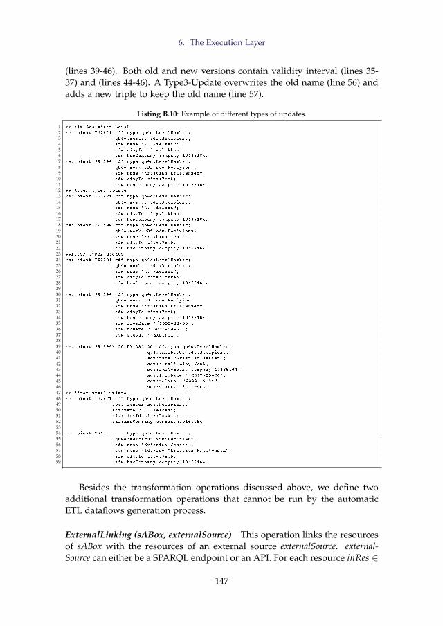
6. The Execution Layer
(lines 39-46). Both old and new versions contain validity interval (lines 35-37) and (lines 44-46). A Type3-Update overwrites the old name (line 56) andadds a new triple to keep the old name (line 57).
Listing B.10: Example of different types of updates.
1 ## sdw:Recipient Level
2 recipient :762921 rdf:type qb4o:LevelMember;
3 qb4o:member sdw:Recipient;
4 sdw:name "R. Nielsen";
5 sdw:cityId city:Lokken;
6 sdw:hasCompany company :10165164.
7 recipient :291894 rdf:type qb4o:LevelMember;
8 qb4o:memberOf sdw:Recipient.
9 sdw:name "Kristian Kristensen";
10 sdw:cityId city:Vemb;
11 sdw:hasCompany company :10165164.
12 ## After type1 update
13 recipient :762921 rdf:type qb4o:LevelMember;
14 qb4o:member sdw:Recipient;
15 sdw:name "R. Nielsen";
16 sdw:cityId city:Lokken;
17 sdw:hasCompany company :10165164.
18 recipient :291894 rdf:type qb4o:LevelMember;
19 qb4o:memberOf sdw:Recipient.
20 sdw:name "Kristian Jensen";
21 sdw:cityId city:Vemb;
22 sdw:hasCompany company :10165164.
23 ##After type2 update
24 recipient :762921 rdf:type qb4o:LevelMember;
25 qb4o:member sdw:Recipient;
26 sdw:name "R. Nielsen";
27 sdw:cityId city:Lokken;
28 sdw:hasCompany company :10165164.
2930 recipient :291894 rdf:type qb4o:LevelMember;
31 qb4o:memberOf sdw:Recipient.
32 sdw:name "Kristian Kristensen";
33 sdw:cityId city:Vemb;
34 sdw:hasCompany company :10165164.
35 sdw:fromDate ``0000-00-00";
36 sdw:toDate ``2017-09-25";
37 sdw:status ``Expired".
3839 recipient :291894\ _2017\_09\_26 rdf:type qb4o:LevelMember;
40 qb4o:memberOf sdw:Recipient.
41 sdw:name "Kristian Jensen";
42 sdw:cityId city:Vemb;
43 sdw:hasCompany company :10165164;
44 sdw:fromDate ``2017-09-26";
45 sdw:toDate ``9999-12-31";
46 sdw:status ``Current".
47 ## After type3 update
48 recipient :762921 rdf:type qb4o:LevelMember;
49 qb4o:member sdw:Recipient;
50 sdw:name "R. Nielsen";
51 sdw:cityId city:Lokken;
52 sdw:hasCompany company :10165164.
5354 recipient :291894 rdf:type qb4o:LevelMember;
55 qb4o:memberOf sdw:Recipient.
56 sdw:name "Kristian Jensen";
57 sdw:name_oldValue "Kristian Kristensen";
58 sdw:cityId city:Vemb;
59 sdw:hasCompany company :10165164.
Besides the transformation operations discussed above, we define twoadditional transformation operations that cannot be run by the automaticETL dataflows generation process.
ExternalLinking (sABox, externalSource) This operation links the resourcesof sABox with the resources of an external source externalSource. external-Source can either be a SPARQL endpoint or an API. For each resource inRes ∈
147
Paper B.
sABox, this operation extracts top k matching external resources either 1) sub-mitting a query to externalSource or 2) by sending a web service request em-bedding inRes through the API (e.g., DBpedia lookup API). To find a potentiallink for each external resource exRes, the Jaccard Similarity of the semanticbags of inRes and exRes is computed. The semantic bag of a resource con-sists of triples describing the resource [38, 39, 50]. The pair of the internaland external resources is considered as a match if the Jaccard Similarity ex-ceeds a certain threshold. A triple with the owl:sameAs property is created tomaterialize the link in sABox for each pair of matched internal and externalresources.
MaterializeInference(ABox, TBox) This operation infers new informationthat has not been explicitly stated in an SDW. It analyzes the semantics en-coded into the SDW and enriches the SDW with the inferred triples. A subsetof the OWL 2 RL/RDF rules, which encodes part of the RDF-Based Seman-tics of OWL 2 [45], are considered here. The reasoning rules can be appliedover the TBox TBox and ABox ABox separately, and then together. Finally,the resulting inference is asserted in the form of triples, in the same spirit ashow SPARQL deals with inference.
6.3 Load
Loader(tripleSet, tsPath) An SDW is represented in the form of RDF triplesand the triples are stored in a triple store (e.g., Jena TDB). Given a set of RDFtriples triplesSet and the path of a triple store tsPath, this operation loadstriplesSet in the triple store.
If the ETL execution flow is generated automatically, this operation firstidentifies the concept-mapping cm from aMappings, where aConstruct ap-pears and the operation to process cm is Loader. Then, it takes values ofmap:sourceLocation and map:targetLocation for the parameters tripleSetand tsPath.
7 Automatic ETL Execution Flow Generation
We can characterize ETL flows at the Definition Layer by means of the source-to-target mapping file; therefore, the ETL data flows in the Execution Layercan be generated automatically. This way, we can guarantee that the cre-ated ETL data flows are sound and relieve the developer from creating theETL data flows manually. Note that this is possible because the MediatoryConstructs (see Figure B.5) contain all the required metadata to automate theprocess.
148
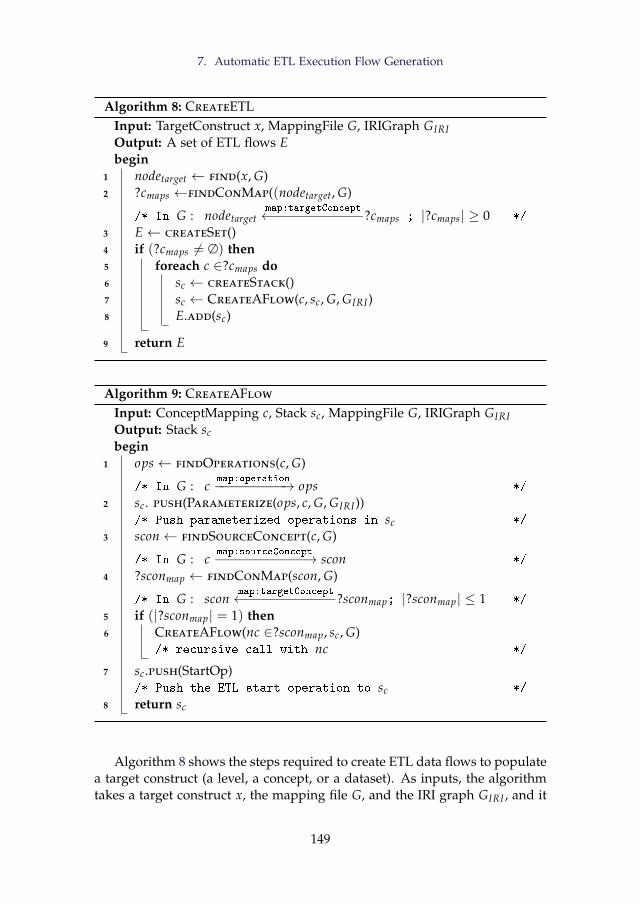
7. Automatic ETL Execution Flow Generation
Algorithm 8: CreateETLInput: TargetConstruct x, MappingFile G, IRIGraph GIRIOutput: A set of ETL flows Ebegin
1 nodetarget ← find(x, G)2 ?cmaps ←findConMap((nodetarget, G)
/* In G : nodetargetmap:targetConcept←−−−−−−−−−−−?cmaps ; |?cmaps| ≥ 0 */
3 E← createSet()4 if (?cmaps 6= ∅) then5 foreach c ∈?cmaps do6 sc ← createStack()7 sc ← CreateAFlow(c, sc, G, GIRI)8 E.add(sc)
9 return E
Algorithm 9: CreateAFlow
Input: ConceptMapping c, Stack sc, MappingFile G, IRIGraph GIRIOutput: Stack scbegin
1 ops← findOperations(c, G)
/* In G : cmap:operation−−−−−−−−−→ ops */
2 sc. push(Parameterize(ops, c, G, GIRI))/* Push parameterized operations in sc */
3 scon← findSourceConcept(c, G)
/* In G : cmap:sourceConcept−−−−−−−−−−−→ scon */
4 ?sconmap ← findConMap(scon, G)
/* In G : sconmap:targetConcept←−−−−−−−−−−−?sconmap; |?sconmap| ≤ 1 */
5 if (|?sconmap| = 1) then6 CreateAFlow(nc ∈?sconmap, sc, G)
/* recursive call with nc */
7 sc.push(StartOp)/* Push the ETL start operation to sc */
8 return sc
Algorithm 8 shows the steps required to create ETL data flows to populatea target construct (a level, a concept, or a dataset). As inputs, the algorithmtakes a target construct x, the mapping file G, and the IRI graph GIRI , and it
149
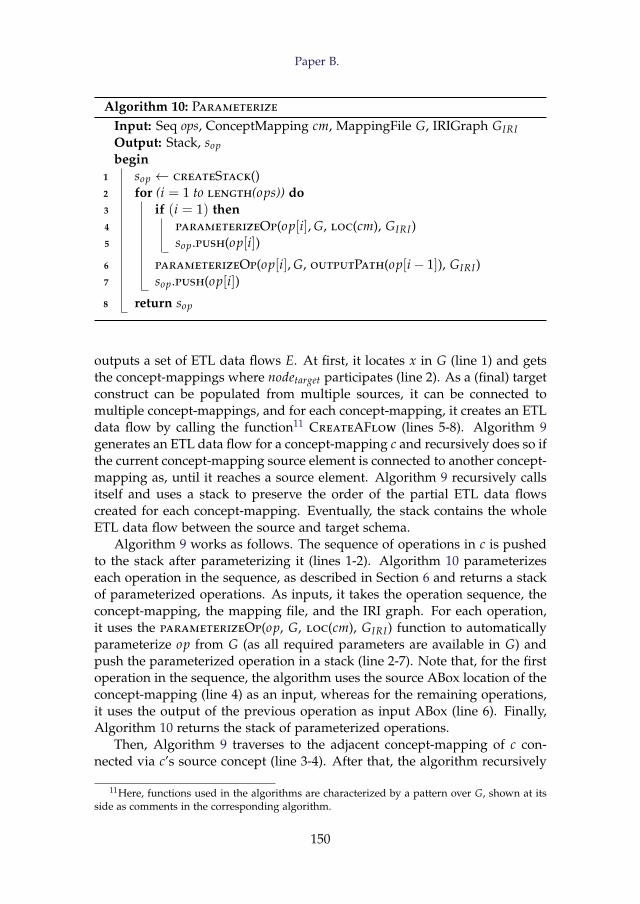
Paper B.
Algorithm 10: Parameterize
Input: Seq ops, ConceptMapping cm, MappingFile G, IRIGraph GIRIOutput: Stack, sopbegin
1 sop ← createStack()2 for (i = 1 to length(ops)) do3 if (i = 1) then4 parameterizeOp(op[i], G, loc(cm), GIRI)5 sop.push(op[i])
6 parameterizeOp(op[i], G, outputPath(op[i− 1]), GIRI)7 sop.push(op[i])
8 return sop
outputs a set of ETL data flows E. At first, it locates x in G (line 1) and getsthe concept-mappings where nodetarget participates (line 2). As a (final) targetconstruct can be populated from multiple sources, it can be connected tomultiple concept-mappings, and for each concept-mapping, it creates an ETLdata flow by calling the function11 CreateAFlow (lines 5-8). Algorithm 9generates an ETL data flow for a concept-mapping c and recursively does so ifthe current concept-mapping source element is connected to another concept-mapping as, until it reaches a source element. Algorithm 9 recursively callsitself and uses a stack to preserve the order of the partial ETL data flowscreated for each concept-mapping. Eventually, the stack contains the wholeETL data flow between the source and target schema.
Algorithm 9 works as follows. The sequence of operations in c is pushedto the stack after parameterizing it (lines 1-2). Algorithm 10 parameterizeseach operation in the sequence, as described in Section 6 and returns a stackof parameterized operations. As inputs, it takes the operation sequence, theconcept-mapping, the mapping file, and the IRI graph. For each operation,it uses the parameterizeOp(op, G, loc(cm), GIRI) function to automaticallyparameterize op from G (as all required parameters are available in G) andpush the parameterized operation in a stack (line 2-7). Note that, for the firstoperation in the sequence, the algorithm uses the source ABox location of theconcept-mapping (line 4) as an input, whereas for the remaining operations,it uses the output of the previous operation as input ABox (line 6). Finally,Algorithm 10 returns the stack of parameterized operations.
Then, Algorithm 9 traverses to the adjacent concept-mapping of c con-nected via c’s source concept (line 3-4). After that, the algorithm recursively
11Here, functions used in the algorithms are characterized by a pattern over G, shown at itsside as comments in the corresponding algorithm.
150
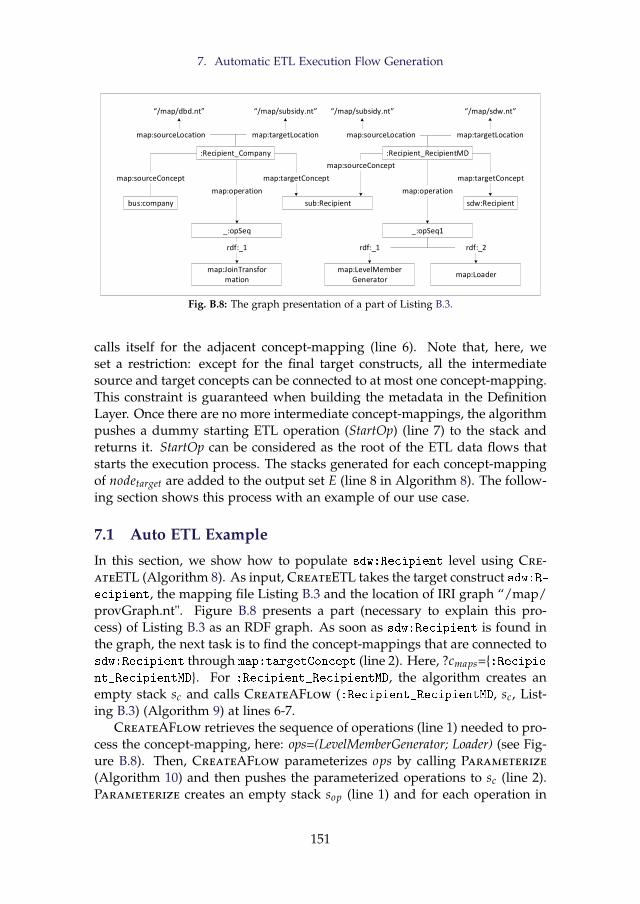
7. Automatic ETL Execution Flow Generation
sdw:Recipient
:Recipient_RecipientMD
sub:Recipient
:Recipient_Company
bus:company
map:targetConcept
map:sourceConcept
map:targetConceptmap:sourceConcept
_:opSeq1
map:LevelMemberGenerator
map:Loader
map:operation
rdf:_1 rdf:_2
_:opSeq
map:operation
map:JoinTransformation
rdf:_1
“/map/dbd.nt” “/map/subsidy.nt” “/map/subsidy.nt” “/map/sdw.nt”
map:sourceLocation map:targetLocation map:targetLocationmap:sourceLocation
Fig. B.8: The graph presentation of a part of Listing B.3.
calls itself for the adjacent concept-mapping (line 6). Note that, here, weset a restriction: except for the final target constructs, all the intermediatesource and target concepts can be connected to at most one concept-mapping.This constraint is guaranteed when building the metadata in the DefinitionLayer. Once there are no more intermediate concept-mappings, the algorithmpushes a dummy starting ETL operation (StartOp) (line 7) to the stack andreturns it. StartOp can be considered as the root of the ETL data flows thatstarts the execution process. The stacks generated for each concept-mappingof nodetarget are added to the output set E (line 8 in Algorithm 8). The follow-ing section shows this process with an example of our use case.
7.1 Auto ETL Example
In this section, we show how to populate sdw:Recipient level using Cre-ateETL (Algorithm 8). As input, CreateETL takes the target construct sdw:R-ecipient, the mapping file Listing B.3 and the location of IRI graph “/map/provGraph.nt". Figure B.8 presents a part (necessary to explain this pro-cess) of Listing B.3 as an RDF graph. As soon as sdw:Recipient is found inthe graph, the next task is to find the concept-mappings that are connected tosdw:Recipient through map:targetConcept (line 2). Here, ?cmaps={:Recipie-nt_RecipientMD}. For :Recipient_RecipientMD, the algorithm creates anempty stack sc and calls CreateAFlow (:Recipient_RecipientMD, sc, List-ing B.3) (Algorithm 9) at lines 6-7.
CreateAFlow retrieves the sequence of operations (line 1) needed to pro-cess the concept-mapping, here: ops=(LevelMemberGenerator; Loader) (see Fig-ure B.8). Then, CreateAFlow parameterizes ops by calling Parameterize
(Algorithm 10) and then pushes the parameterized operations to sc (line 2).Parameterize creates an empty stack sop (line 1) and for each operation in
151
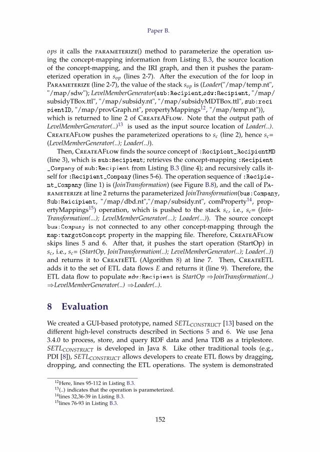
Paper B.
ops it calls the parameterize() method to parameterize the operation us-ing the concept-mapping information from Listing B.3, the source locationof the concept-mapping, and the IRI graph, and then it pushes the param-eterized operation in sop (lines 2-7). After the execution of the for loop inParameterize (line 2-7), the value of the stack sop is (Loader("/map/temp.nt","/map/sdw"); LevelMemberGenerator(sub:Recipient,sdw:Recipient, "/map/subsidyTBox.ttl", "/map/subsidy.nt", "/map/subsidyMDTBox.ttl", sub:reci-pientID, "/map/provGraph.nt", propertyMappings12, "/map/temp.nt")),which is returned to line 2 of CreateAFlow. Note that the output path ofLevelMemberGenerator(..)13 is used as the input source location of Loader(..).CreateAFlow pushes the parameterized operations to sc (line 2), hence sc=(LevelMemberGenerator(..); Loader(..)).
Then, CreateAFlow finds the source concept of :Recipient_RecipientMD(line 3), which is sub:Recipient; retrieves the concept-mapping :Recipient
_Company of sub:Recipient from Listing B.3 (line 4); and recursively calls it-self for :Recipient_Company (lines 5-6). The operation sequence of :Recipie-nt_Company (line 1) is (JoinTransformation) (see Figure B.8), and the call of Pa-rameterize at line 2 returns the parameterized JoinTransformation(bus:Company,Sub:Reicipient, "/map/dbd.nt","/map/subsidy.nt", comProperty14, prop-ertyMappings15) operation, which is pushed to the stack sc, i.e., sc= (Join-Transformation(...); LevelMemberGenerator(...); Loader(...)). The source conceptbus:Company is not connected to any other concept-mapping through themap:targetConcept property in the mapping file. Therefore, CreateAFlow
skips lines 5 and 6. After that, it pushes the start operation (StartOp) insc, i.e., sc= (StartOp, JoinTransformation(..); LevelMemberGenerator(..); Loader(..))and returns it to CreateETL (Algorithm 8) at line 7. Then, CreateETLadds it to the set of ETL data flows E and returns it (line 9). Therefore, theETL data flow to populate sdw:Recipient is StartOp ⇒JoinTransformation(..)⇒LevelMemberGenerator(..) ⇒Loader(..).
8 Evaluation
We created a GUI-based prototype, named SETLCONSTRUCT [13] based on thedifferent high-level constructs described in Sections 5 and 6. We use Jena3.4.0 to process, store, and query RDF data and Jena TDB as a triplestore.SETLCONSTRUCT is developed in Java 8. Like other traditional tools (e.g.,PDI [8]), SETLCONSTRUCT allows developers to create ETL flows by dragging,dropping, and connecting the ETL operations. The system is demonstrated
12Here, lines 95-112 in Listing B.3.13(..) indicates that the operation is parameterized.14lines 32,36-39 in Listing B.3.15lines 76-93 in Listing B.3.
152
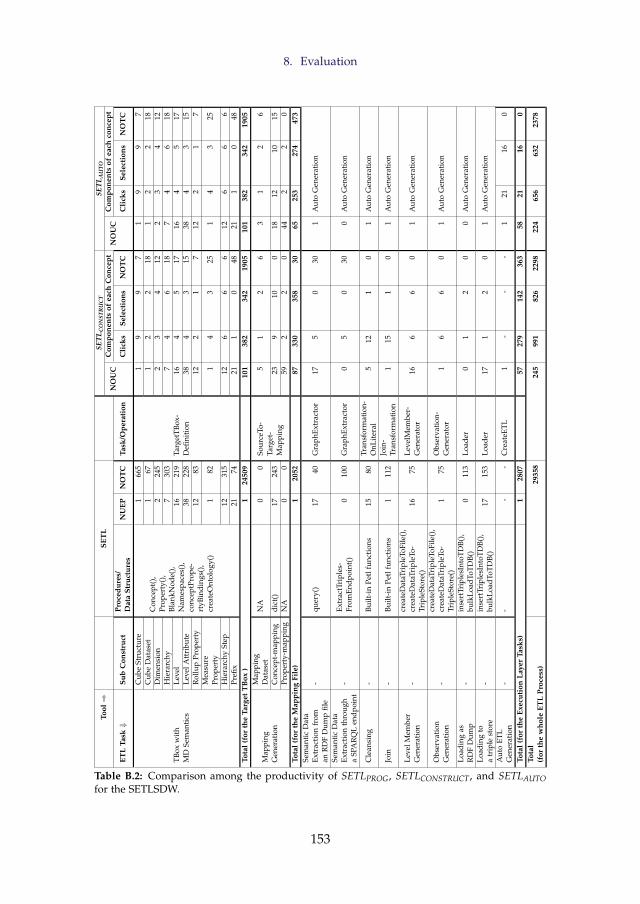
8. Evaluation
Tool⇒
SET
LSE
TLC
ON
STR
UC
TSE
TLA
UTO
NO
UC
Com
pone
nts
ofea
chC
once
ptN
OU
CC
ompo
nent
sof
each
conc
ept
ETL
Task⇓
Sub
Con
stru
ctPr
oced
ures
/D
ata
Stru
ctur
esN
UEP
NO
TC
Task
/Ope
rati
onC
lick
sSe
lect
ions
NO
TC
Cli
cks
Sele
ctio
nsN
OT
C
TBox
wit
hM
DSe
man
tics
Cub
eSt
ruct
ure
Con
cept
(),
Prop
erty
(),
Blan
kNod
e(),
Nam
espa
ces(
),co
ncep
tPro
pe-
rtyB
indi
ngs(
),cr
eate
Ont
olog
y()
166
5
Targ
etTB
ox-
Defi
niti
on
19
97
19
97
Cub
eD
atas
et1
671
22
181
22
18D
imen
sion
224
52
34
122
34
12H
iera
rchy
730
37
46
187
46
18Le
vel
1621
916
45
1716
45
17Le
velA
ttri
bute
3822
838
43
1538
43
15R
ollu
pPr
oper
ty12
8312
21
712
21
7M
easu
rePr
oper
ty1
821
43
251
43
25
Hie
rarc
hySt
ep12
315
126
66
126
66
Prefi
x21
7421
10
4821
10
48To
tal
(for
the
Targ
etT
Box
)1
2450
910
138
234
219
0510
138
234
219
05
Map
ping
Gen
erat
ion
Map
ping
Dat
aset
NA
00
Sour
ceTo
-Ta
rget
-M
appi
ng
51
26
31
26
Con
cept
-map
ping
dict
()17
243
239
100
1812
1015
Prop
erty
-map
ping
NA
00
592
20
442
20
Tota
l(f
orth
eM
appi
ngFi
le)
120
5287
330
358
3065
253
274
473
Sem
anti
cD
ata
Extr
acti
onfr
oman
RD
FD
ump
file
-qu
ery(
)17
40G
raph
Extr
acto
r17
50
301
Aut
oG
ener
atio
n
Sem
anti
cD
ata
Extr
acti
onth
roug
ha
SPA
RQ
Len
dpoi
nt-
Extr
actT
ripl
es-
From
Endp
oint
()0
100
Gra
phEx
trac
tor
05
030
0A
uto
Gen
erat
ion
Cle
ansi
ng-
Built
-in
Petl
func
tion
s15
80Tr
ansf
orm
atio
n-O
nLit
eral
512
10
1A
uto
Gen
erat
ion
Join
-Bu
ilt-i
nPe
tlfu
ncti
ons
111
2Jo
in-
Tran
sfor
mat
ion
115
10
1A
uto
Gen
erat
ion
Leve
lMem
ber
Gen
erat
ion
-cr
eate
Dat
aTri
pleT
oFile
(),
crea
teD
ataT
ripl
eTo-
Trip
leSt
ore(
)16
75Le
velM
embe
r-G
ener
ator
166
60
1A
uto
Gen
erat
ion
Obs
erva
tion
Gen
erat
ion
-cr
eate
Dat
aTri
pleT
oFile
(),
crea
teD
ataT
ripl
eTo-
Trip
leSt
ore(
)1
75O
bser
vati
on-
Gen
erat
or1
66
01
Aut
oG
ener
atio
n
Load
ing
asR
DF
Dum
p-
inse
rtTr
iple
sInt
oTD
B(),
bulk
Load
ToT
DB(
)0
113
Load
er0
12
00
Aut
oG
ener
atio
n
Load
ing
toa
trip
lest
ore
-in
sert
Trip
lesI
ntoT
DB(
),bu
lkLo
adTo
TD
B()
1715
3Lo
ader
171
20
1A
uto
Gen
erat
ion
Aut
oET
LG
ener
atio
n-
--
-C
reat
eETL
1-
--
121
160
Tota
l(f
orth
eEx
ecut
ion
Laye
rTa
sks)
128
0757
279
142
363
5821
160
Tota
l(f
orth
ew
hole
ETL
Proc
ess)
2935
824
599
182
622
9822
465
663
223
78
Table B.2: Comparison among the productivity of SETLPROG, SETLCONSTRUCT, and SETLAUTOfor the SETLSDW.
153
Paper B.
in [13]. On top of SETLCONSTRUCT, we implement the automatic ETL exe-cution flow generation process discussed in Section 7; we call it SETLAUTO.The source code, examples, and developer manual for SETLCONSTRUCT andSETLAUTO are available at https://github.com/bi-setl/SETL.
To evaluate SETLCONSTRUCT and SETLAUTO, we create an MD SDW byintegrating the Danish Business Dataset (DBD) [3] and the Subsidy dataset( https://data.farmsubsidy.org/Old/), described in Section 2. We choosethis use case and these datasets for evaluation as there already exists an MDSDW, based on these datasets, that has been programatically created usingSETLPROG [37]. Our evaluation focuses on three aspects: 1) productivity, i.e.,to what extent SETLCONSTRUCT and SETLAUTO ease the work of a developerwhen developing an ETL task to process semantic data, 2) development time,the time to develop an ETL process, and 3) performance, the time required torun the process. We run the experiments on a laptop with a 2.10 GHz IntelCore(TM) i7-4600U processor, 8 GB RAM, and Windows 10.
8.1 Productivity
SETLPROG requires Python knowledge to maintain and implement an ETLprocess. On the other hand, using SETLCONSTRUCT and SETLAUTO, a devel-oper can create all the phases of an ETL process by interacting with a GUI.Therefore, they provide a higher level of abstraction to the developer thathides low-level details and requires no programming background. Table B.2summarizes the effort required by the developer to create different ETL tasksusing SETLPROG, SETLCONSTRUCT, and SETLAUTO. We measure the developereffort in terms of Number of Typed Characters (NOTC) for SETLPROG andin Number of Used Concepts (NOUC) for SETLCONSTRUCT and SETLAUTO.Here, we define a concept as a GUI component of SETLCONSTRUCT that opensa new window to perform a specific action. A concept is composed of sev-eral clicks, selections, and typed characters. For each ETL task, Table B.2lists: 1) its sub construct, required procedures/data structures, number ofthe task used in the ETL process (NUEP), and NOTC for SETLPROG; 2) the re-quired task/operation, NOUC, and number of clicks, selections, and NOTC(for each concept) for SETLCONSTRUCT and SETLAUTO. Note that NOTC de-pends on the user input. Here, we generalize it by using same user input forall systems. Therefore, the total NOTC is not the summation of the values ofthe respective column.
To create a target TBox using SETLPROG, an ETL developer needs to usethe following steps: 1) defining the TBox constructs by instantiating the Con-cept, Property, and BlankNode classes that play a meta modeling role for theconstructs and 2) calling conceptPropertyBinding() and createTriples(). Both pro-cedures take the list of all concepts, properties, and blank nodes as param-eters. The former one internally connects the constructs to each other, and
154
8. Evaluation
the latter creates triples for the TBox. To create the TBox of our SETLSDWusing SETLPROG, we used 24,509 NOTC. On the other hand, SETLCONSTRUCTand SETLAUTO use the TargetTBoxDefinition interface to create/edit a targetTBox. To create the target TBox of our SETLSDW in SETLCONSTRUCT andSETLAUTO, we use 101 concepts that require only 382 clicks, 342 selections,and 1905 NOTC. Therefore, for creating a target TBox, SETLCONSTRUCT andSETLAUTO reduce use 92% fewer NOTC than SETLPROG.
To create source-to-target mappings, SETLPROG uses Python dictionarieswhere the keys of each dictionary represent source constructs and values arethe mapped target TBox constructs, and for creating the ETL process it uses23 dictionaries, where the biggest dictionary used in the ETL process takes253 NOTC. In total, SETLPROG uses 2052 NOTC for creating mappings forthe whole ETL process. On the contrary, SETLCONSTRUCT and SETLAUTO usea GUI. In total, SETLCONSTRUCT uses 87 concepts composed of 330 clicks, 358selections, and 30 NOTC. Since SETLAUTO internally creates the intermediatemappings, there is no need to create separate mapping datasets and concept-mappings for intermediate results. Thus, SETLAUTO uses only 65 concepts re-quiring 253 clicks, 274 selections, and 473 NOTC. Therefore, SETLCONSTRUCTreduces NOTC of SETLPROG by 98%. Although SETLAUTO uses 22 less con-cepts than SETLCONSTRUCT, SETLCONSTRUCT reduces NOTC of SETLAUTO by93%. This is because, in SETLAUTO, we write the data extraction queries inthe concept-mappings where in SETLCONSTRUCT we set the data extractionqueries in the ETL operation level.
To extract data from either an RDF local file or an SPARQL endpoint,SETLPROG uses the query() procedure and the ExtractTriplesFromEndpoint()class. On the other hand, SETLCONSTRUCT uses the GraphExtractor operation.It uses 1 concept composed of 5 clicks and 20 NOTC for the local file and 1concept with 5 clicks and 30 NOTC for the endpoint.
SETLPROG uses different functions/procedures from the Petl Python li-brary (integrated with SETL) based on the cleansing requirements. In SETLC-
ONSTRUCT, all data cleansing related tasks on data sources are done usingTransformationOnLiteral (single source) and JoinTransformation (for multi-source).TransformationOnLiteral requires 12 clicks and 1 selection, and JoinTransforma-tion takes 15 clicks and 1 selection. To create a level member and observation,SETLPROG uses createDataTripleToFile() and takes 125 NOTC. The proceduretakes all the classes, properties, and blank nodes of a target TBox as input;therefore, the given TBox should be parsed for being used in the procedure.On the other hand, SETLCONSTRUCT uses the LevelMemberGenerator and Ob-servationGenerator operations, and each operation requires 1 concept, whichtakes 6 clicks and 6 selections. SETLPROG provides procedures for either bulkor trickle loading to a file or an endpoint. Both procedures take 113 and 153NOTC, respectively. For loading RDF triples either to a file or a triple store,SETLCONSTRUCT uses the Loader operation, which needs 2 clicks and 2 selec-
155
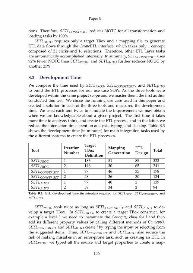
Paper B.
tions. Therefore, SETLCONSTRUCT reduces NOTC for all transformation andloading tasks by 100%.
SETLAUTO requires only a target TBox and a mapping file to generateETL data flows through the CreateETL interface, which takes only 1 conceptcomposed of 21 clicks and 16 selections. Therefore, other ETL Layer tasksare automatically accomplished internally. In summary, SETLCONSTRUCT uses92% fewer NOTC than SETLPROG, and SETLAUTO further reduces NOUC byanother 25%.
8.2 Development Time
We compare the time used by SETLPROG, SETLCONSTRUCT, and SETLAUTOto build the ETL processes for our use case SDW. As the three tools weredeveloped within the same project scope and we master them, the first authorconducted this test. We chose the running use case used in this paper andcreated a solution in each of the three tools and measured the developmenttime. We used each tool twice to simulate the improvement we may obtainwhen we are knowledgeable about a given project. The first time it takesmore time to analyze, think, and create the ETL process, and in the latter, wereduce the interaction time spent on analysis, typing, and clicking. Table B.3shows the development time (in minutes) for main integration tasks used bythe different systems to create the ETL processes.
ToolIterationNumber
TargetTBoxDefinition
MappingGenerartion
ETLDesign
Total
SETLPROG 1 186 51 85 322SETLPROG 2 146 30 65 241SETLCONSTRUCT 1 97 46 35 178SETLCONSTRUCT 2 58 36 30 124SETLAUTO 1 97 40 2 139SETLAUTO 2 58 34 2 94
Table B.3: ETL development time (in minutes) required for SETLPROG, SETLCONSTRUCT, andSETLAUTO.
SETLPROG took twice as long as SETLCONSTRUCT and SETLAUTO to de-velop a target TBox. In SETLPROG, to create a target TBox construct, forexample a level l, we need to instantiate the Concept() class for l and thenadd its different property values by calling different methods of Concept().SETLCONSTRUCT and SETLAUTO create l by typing the input or selecting fromthe suggested items. Thus, SETLCONSTRUCT and SETLAUTO also reduce therisk of making mistakes in an error-prone task, such as creating an ETL. InSETLPROG, we typed all the source and target properties to create a map-
156
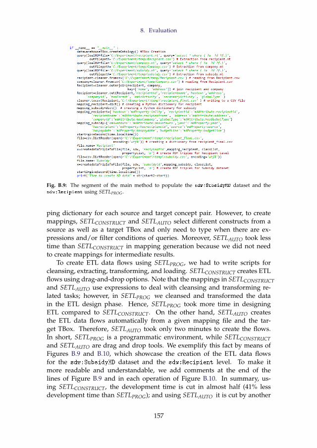
8. Evaluation
Fig. B.9: The segment of the main method to populate the sdw:SubsidyMD dataset and thesdw:Recipient using SETLPROG.
ping dictionary for each source and target concept pair. However, to createmappings, SETLCONSTRUCT and SETLAUTO select different constructs from asource as well as a target TBox and only need to type when there are ex-pressions and/or filter conditions of queries. Moreover, SETLAUTO took lesstime than SETLCONSTRUCT in mapping generation because we did not needto create mappings for intermediate results.
To create ETL data flows using SETLPROG, we had to write scripts forcleansing, extracting, transforming, and loading. SETLCONSTRUCT creates ETLflows using drag-and-drop options. Note that the mappings in SETLCONSTRUCTand SETLAUTO use expressions to deal with cleansing and transforming re-lated tasks; however, in SETLPROG we cleansed and transformed the datain the ETL design phase. Hence, SETLPROG took more time in designingETL compared to SETLCONSTRUCT. On the other hand, SETLAUTO createsthe ETL data flows automatically from a given mapping file and the tar-get TBox. Therefore, SETLAUTO took only two minutes to create the flows.In short, SETLPROG is a programmatic environment, while SETLCONSTRUCTand SETLAUTO are drag and drop tools. We exemplify this fact by means ofFigures B.9 and B.10, which showcase the creation of the ETL data flowsfor the sdw:SubsidyMD dataset and the sdw:Recipient level. To make itmore readable and understandable, we add comments at the end of thelines of Figure B.9 and in each operation of Figure B.10. In summary, us-ing SETLCONSTRUCT, the development time is cut in almost half (41% lessdevelopment time than SETLPROG); and using SETLAUTO it is cut by another
157
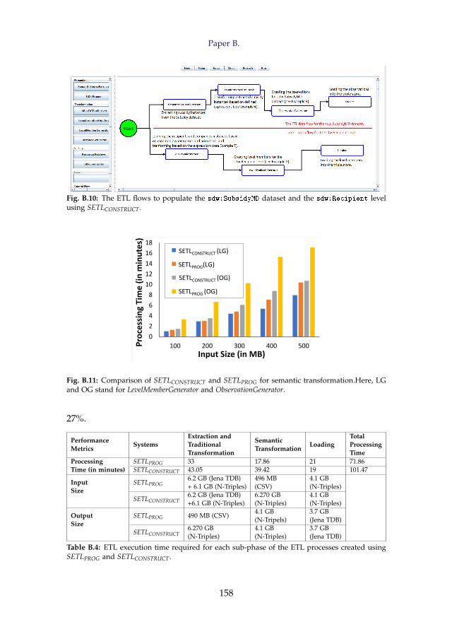
Paper B.
Fig. B.10: The ETL flows to populate the sdw:SubsidyMD dataset and the sdw:Recipient levelusing SETLCONSTRUCT.
0
2
4
6
8
10
12
14
16
18
100 200 300 400 500Pro
cess
ing
Tim
e (
in m
inu
tes)
Input Size (in MB)
SETLCONSTRUCT(LG)
SETLPROG(LG)
SETLCONSTRICT(OG)
SETLPROG(OG)
SETLPROG(LG)
SETLCONSTRUCT (LG)
SETLCONSTRUCT (OG)
SETLPROG (OG)
Fig. B.11: Comparison of SETLCONSTRUCT and SETLPROG for semantic transformation.Here, LGand OG stand for LevelMemberGenerator and ObservationGenerator.
27%.
PerformanceMetrics
SystemsExtraction andTraditionalTransformation
SemanticTransformation
LoadingTotalProcessingTime
ProcessingTime (in minutes)
SETLPROG 33 17.86 21 71.86SETLCONSTRUCT 43.05 39.42 19 101.47
InputSize
SETLPROG6.2 GB (Jena TDB)+ 6.1 GB (N-Triples)
496 MB(CSV)
4.1 GB(N-Triples)
SETLCONSTRUCT6.2 GB (Jena TDB)+6.1 GB (N-Triples)
6.270 GB(N-Triples)
4.1 GB(N-Triples)
OutputSize
SETLPROG 490 MB (CSV)4.1 GB(N-Tripels)
3.7 GB(Jena TDB)
SETLCONSTRUCT6.270 GB(N-Triples)
4.1 GB(N-Triples)
3.7 GB(Jena TDB)
Table B.4: ETL execution time required for each sub-phase of the ETL processes created usingSETLPROG and SETLCONSTRUCT.
158
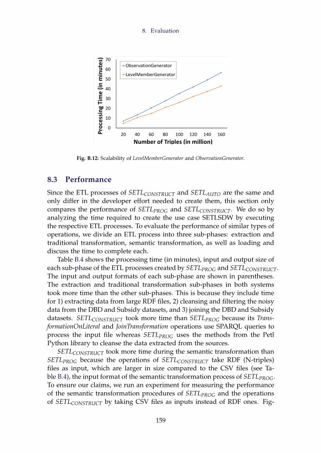
8. Evaluation
0
10
20
30
40
50
60
70
20 40 60 80 100 120 140 160Pro
cess
ing
Tim
e (
in m
inu
tes)
Number of Triples (in million)
ObservationGenerator
LevelMemberGenerator
Fig. B.12: Scalability of LevelMemberGenerator and ObservationGenerator.
8.3 Performance
Since the ETL processes of SETLCONSTRUCT and SETLAUTO are the same andonly differ in the developer effort needed to create them, this section onlycompares the performance of SETLPROG and SETLCONSTRUCT. We do so byanalyzing the time required to create the use case SETLSDW by executingthe respective ETL processes. To evaluate the performance of similar types ofoperations, we divide an ETL process into three sub-phases: extraction andtraditional transformation, semantic transformation, as well as loading anddiscuss the time to complete each.
Table B.4 shows the processing time (in minutes), input and output size ofeach sub-phase of the ETL processes created by SETLPROG and SETLCONSTRUCT.The input and output formats of each sub-phase are shown in parentheses.The extraction and traditional transformation sub-phases in both systemstook more time than the other sub-phases. This is because they include timefor 1) extracting data from large RDF files, 2) cleansing and filtering the noisydata from the DBD and Subsidy datasets, and 3) joining the DBD and Subsidydatasets. SETLCONSTRUCT took more time than SETLPROG because its Trans-formationOnLiteral and JoinTransformation operations use SPARQL queries toprocess the input file whereas SETLPROG uses the methods from the PetlPython library to cleanse the data extracted from the sources.
SETLCONSTRUCT took more time during the semantic transformation thanSETLPROG because the operations of SETLCONSTRUCT take RDF (N-triples)files as input, which are larger in size compared to the CSV files (see Ta-ble B.4), the input format of the semantic transformation process of SETLPROG.To ensure our claims, we run an experiment for measuring the performanceof the semantic transformation procedures of SETLPROG and the operationsof SETLCONSTRUCT by taking CSV files as inputs instead of RDF ones. Fig-
159
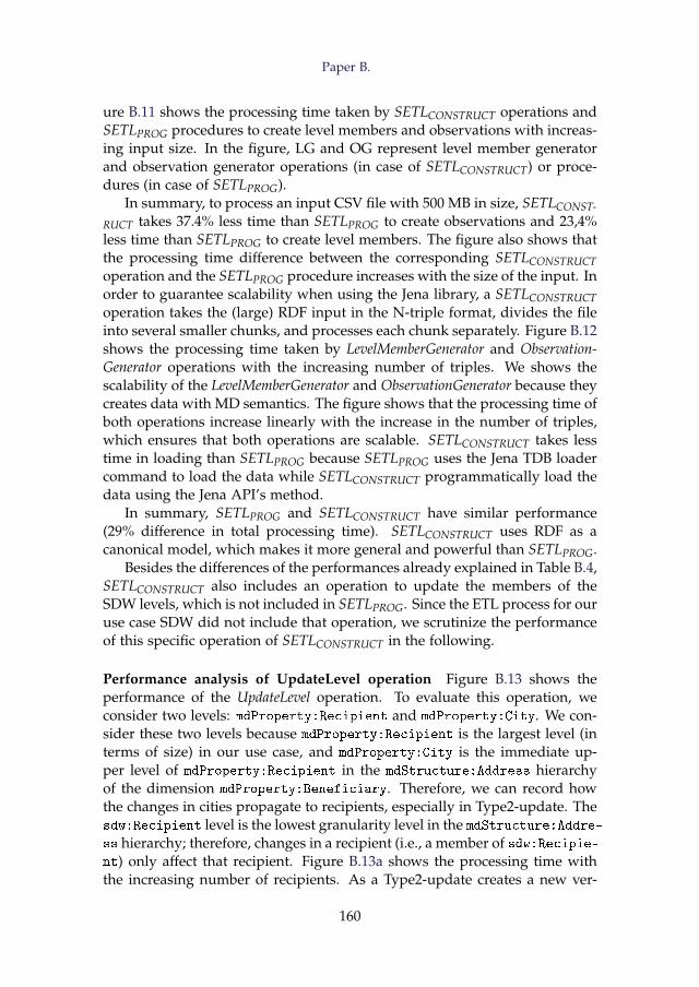
Paper B.
ure B.11 shows the processing time taken by SETLCONSTRUCT operations andSETLPROG procedures to create level members and observations with increas-ing input size. In the figure, LG and OG represent level member generatorand observation generator operations (in case of SETLCONSTRUCT) or proce-dures (in case of SETLPROG).
In summary, to process an input CSV file with 500 MB in size, SETLCONST-
RUCT takes 37.4% less time than SETLPROG to create observations and 23,4%less time than SETLPROG to create level members. The figure also shows thatthe processing time difference between the corresponding SETLCONSTRUCToperation and the SETLPROG procedure increases with the size of the input. Inorder to guarantee scalability when using the Jena library, a SETLCONSTRUCToperation takes the (large) RDF input in the N-triple format, divides the fileinto several smaller chunks, and processes each chunk separately. Figure B.12shows the processing time taken by LevelMemberGenerator and Observation-Generator operations with the increasing number of triples. We shows thescalability of the LevelMemberGenerator and ObservationGenerator because theycreates data with MD semantics. The figure shows that the processing time ofboth operations increase linearly with the increase in the number of triples,which ensures that both operations are scalable. SETLCONSTRUCT takes lesstime in loading than SETLPROG because SETLPROG uses the Jena TDB loadercommand to load the data while SETLCONSTRUCT programmatically load thedata using the Jena API’s method.
In summary, SETLPROG and SETLCONSTRUCT have similar performance(29% difference in total processing time). SETLCONSTRUCT uses RDF as acanonical model, which makes it more general and powerful than SETLPROG.
Besides the differences of the performances already explained in Table B.4,SETLCONSTRUCT also includes an operation to update the members of theSDW levels, which is not included in SETLPROG. Since the ETL process for ouruse case SDW did not include that operation, we scrutinize the performanceof this specific operation of SETLCONSTRUCT in the following.
Performance analysis of UpdateLevel operation Figure B.13 shows theperformance of the UpdateLevel operation. To evaluate this operation, weconsider two levels: mdProperty:Recipient and mdProperty:City. We con-sider these two levels because mdProperty:Recipient is the largest level (interms of size) in our use case, and mdProperty:City is the immediate up-per level of mdProperty:Recipient in the mdStructure:Address hierarchyof the dimension mdProperty:Beneficiary. Therefore, we can record howthe changes in cities propagate to recipients, especially in Type2-update. Thesdw:Recipient level is the lowest granularity level in the mdStructure:Addre-ss hierarchy; therefore, changes in a recipient (i.e., a member of sdw:Recipie-nt) only affect that recipient. Figure B.13a shows the processing time withthe increasing number of recipients. As a Type2-update creates a new ver-
160
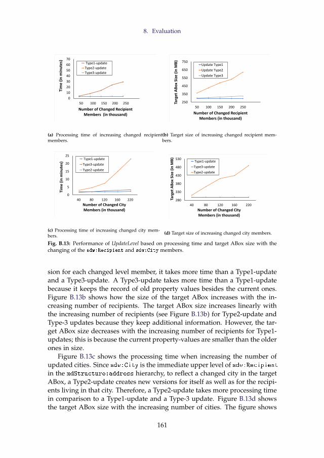
8. Evaluation
0
10
20
30
40
50
60
70Ti
me
(in
min
ute
s)
Number of Changed Recipient Members (in thousand)
Type1-update
Type2-update
Type3-update
(a) Processing time of increasing changed recipientmembers.
250
350
450
550
650
750
50 100 150 200 250
Targ
et A
Bo
x Si
ze (
in M
B)
Number of Changed Recipient Members (in thousand)
Update Type1
Update Type2
Update Type3
(b) Target size of increasing changed recipient mem-bers.
0
5
10
15
20
25
40 80 120 160 220
Tim
e (
in m
inu
tes)
Number of Changed City Members (in thousand)
Type1-update
Type3-update
Type2-update
(c) Processing time of increasing changed city mem-bers.
280
330
380
430
480
530
40 80 120 160 220
Targ
et A
Bo
x Si
ze (
in M
B)
Number of Changed City Members (in thousand)
Type1-update
Type3-update
Type2-update
(d) Target size of increasing changed city members.
Fig. B.13: Performance of UpdateLevel based on processing time and target ABox size with thechanging of the sdw:Recipient and sdw:City members.
sion for each changed level member, it takes more time than a Type1-updateand a Type3-update. A Type3-update takes more time than a Type1-updatebecause it keeps the record of old property values besides the current ones.Figure B.13b shows how the size of the target ABox increases with the in-creasing number of recipients. The target ABox size increases linearly withthe increasing number of recipients (see Figure B.13b) for Type2-update andType-3 updates because they keep additional information. However, the tar-get ABox size decreases with the increasing number of recipients for Type1-updates; this is because the current property-values are smaller than the olderones in size.
Figure B.13c shows the processing time when increasing the number ofupdated cities. Since sdw:City is the immediate upper level of sdw:Recipientin the mdStructure:address hierarchy, to reflect a changed city in the targetABox, a Type2-update creates new versions for itself as well as for the recipi-ents living in that city. Therefore, a Type2-update takes more processing timein comparison to a Type1-update and a Type-3 update. Figure B.13d showsthe target ABox size with the increasing number of cities. The figure shows
161
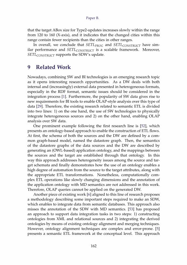
Paper B.
that the target ABox size for Type2-updates increases slowly within the rangefrom 120 to 160 (X-axis), and it indicates that the changed cities within thisrange contain fewer recipients than the cities in other ranges.
In overall, we conclude that SETLPROG and SETLCONSTRUCT have sim-ilar performance and SETLCONSTRUCT is a scalable framework. Moreover,SETLCONSTRUCT supports the SDW’s update.
9 Related Work
Nowadays, combining SW and BI technologies is an emerging research topicas it opens interesting research opportunities. As a DW deals with bothinternal and (increasingly) external data presented in heterogeneous formats,especially in the RDF format, semantic issues should be considered in theintegration process [1]. Furthermore, the popularity of SW data gives rise tonew requirements for BI tools to enable OLAP-style analysis over this type ofdata [29]. Therefore, the existing research related to semantic ETL is dividedinto two lines: 1) on the one hand, the use of SW technologies to physicallyintegrate heterogeneous sources and 2) on the other hand, enabling OLAPanalysis over SW data.
One prominent example following the first research line is [52], whichpresents an ontology-based approach to enable the construction of ETL flows.At first, the schema of both the sources and the DW are defined by a com-mon graph-based model, named the datastore graph. Then, the semanticsof the datastore graphs of the data sources and the DW are described bygenerating an (OWL-based) application ontology, and the mappings betweenthe sources and the target are established through that ontology. In thisway this approach addresses heterogeneity issues among the source and tar-get schemata and finally demonstrates how the use of an ontology enables ahigh degree of automation from the source to the target attributes, along withthe appropriate ETL transformations. Nonetheless, computationally com-plex ETL operations like slowly changing dimensions and the annotation ofthe application ontology with MD semantics are not addressed in this work.Therefore, OLAP queries cannot be applied on the generated DW.
Another piece of existing work [6] aligned to this line of research proposesa methodology describing some important steps required to make an SDW,which enables to integrate data from semantic databases. This approach alsomisses the annotation of the SDW with MD semantics. [53] has proposedan approach to support data integration tasks in two steps: 1) constructingontologies from XML and relational sources and 2) integrating the derivedontologies by means of existing ontology alignment and merging techniques.However, ontology alignment techniques are complex and error-prone. [5]presents a semantic ETL framework at the conceptual level. This approach
162
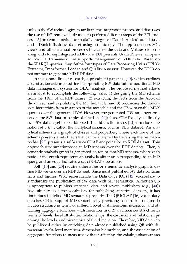
9. Related Work
utilizes the SW technologies to facilitate the integration process and discussesthe use of different available tools to perform different steps of the ETL pro-cess. [3] presents a method to spatially integrate a Danish Agricultural datasetand a Danish Business dataset using an ontology. The approach uses SQLviews and other manual processes to cleanse the data and Virtuoso for cre-ating and storing integrated RDF data. [33] presents UnifiedViews, an open-source ETL framework that supports management of RDF data. Based onthe SPARQL queries, they define four types of Data Processing Units (DPUs):Extractor, Transformer, Loader, and Quality Assessor. However, the DPUs donot support to generate MD RDF data.
In the second line of research, a prominent paper is [40], which outlinesa semi-automatic method for incorporating SW data into a traditional MDdata management system for OLAP analysis. The proposed method allowsan analyst to accomplish the following tasks: 1) designing the MD schemafrom the TBox of an RDF dataset, 2) extracting the facts from the ABox ofthe dataset and populating the MD fact table, and 3) producing the dimen-sion hierarchies from instances of the fact table and the TBox to enable MDXqueries over the generated DW. However, the generated DW no longer pre-serves the SW data principles defined in [24]; thus, OLAP analysis directlyover SW data is yet to be addressed. To address this issue, [10] introduces thenotion of a lens, called the analytical schema, over an RDF dataset. An ana-lytical schema is a graph of classes and properties, where each node of theschema presents a set of facts that can be analyzed by traversing the reachablenodes. [25] presents a self-service OLAP endpoint for an RDF dataset. Thisapproach first superimposes an MD schema over the RDF dataset. Then, asemantic analysis graph is generated on top of that MD schema, where eachnode of the graph represents an analysis situation corresponding to an MDquery, and an edge indicates a set of OLAP operations.
Both [10] and [25] require either a lens or a semantic analysis graph to de-fine MD views over an RDF dataset. Since most published SW data containsfacts and figures, W3C recommends the Data Cube (QB) [12] vocabulary tostandardize the publication of SW data with MD semantics. Although QBis appropriate to publish statistical data and several publishers (e.g., [44])have already used the vocabulary for publishing statistical datasets, it haslimitations to define MD semantics properly. The QB4OLAP [16] vocabularyenriches QB to support MD semantics by providing constructs to define 1)a cube structure in terms of different level of dimensions, measures, and at-taching aggregate functions with measures and 2) a dimension structure interms of levels, level attributes, relationships, the cardinality of relationshipsamong the levels, and hierarchies of the dimension. Therefore, MD data canbe published either by enriching data already published using QB with di-mension levels, level members, dimension hierarchies, and the association ofaggregate functions to measures without affecting the existing observations
163
Paper B.
[55] or using QB4OLAP from scratch [18, 26, 37].In [31], the authors present an approach to enable OLAP operations on
a single data cube published using the QB vocabulary and shown the appli-cability of their OLAP-to-SPARQL mapping in answering business questionsin the financial domain. However, their OLAP-to-SPARQL mapping may notresult in the most efficient SPARQL query and requires additional efforts anda longer time to get the results as they consider that the cube is queried ondemand and the DW is not materialized. While some approaches have pro-posed techniques to optimize execution of OLAP-style SPARQL queries in afederated setting [27], others have considered view materialization [17, 28].The authors in [55] present a semi-automatic method to enrich the QB datasetwith QB4OLAP terms. However, there is no guideline for an ETL process topopulate a DW annotated with QB4OLAP terms.
After analyzing the two research lines, we can draw some conclusions. Al-though each approach described above addresses one or more aspects of a se-mantic ETL framework, there is no single platform that supports them all (tar-get definition, source-to-target mappings generation, ETL generations, MDtarget population, and evolution). To solve this problem, we have proposed aPython-based programmable semantic ETL (SETLPROG) framework [37] thatprovides a number of powerful modules, classes, and methods for perform-ing the tasks mentioned above. It facilitates developers by providing a higherabstraction level that lowers the entry barriers. We have experimentallyshown that SETLPROG performs better in terms of programmer productiv-ity, knowledge base quality, and performance, compared to other existingsolutions. However, to use it, developers need a programming background.Although SETLPROG enables to create an ETL flow and provides methods bycombining several tasks, there is a lack of a well-defined set of basic semanticETL constructs that allow users more control in creating their ETL process.Moreover, how to update an SDW to synchronize it with the changes takingplace in the sources is not discussed. Further, in a data lake/big data envi-ronment, the data may come from heterogeneous formats, and the use of therelational model as the canonical model may generate an overhead. Trans-forming JSON or XML data to relational data to finally generate RDF can beavoided by using RDF as the canonical model instead. To this end, severalworks have discussed the appropriateness of knowledge graphs for data in-tegration purposes and specifically, as a canonical data model [11, 48, 49].An additional benefit of using RDF as a canonical model is that it allowsadding semantics without being compliant to a fixed schema. The presentpaper presents the improvements introduced on top of SETLPROG to remedyits main drawbacks discussed above. As there are available RDF Wrappers(e.g., [14, 51]) to convert another format to RDF, in this paper, we focus ononly semantic data and propose an RDF-based two-layered (Definition Layerand Execution Layer) integration process. We also propose a set of high-level
164
10. Conclusion and Future Work
ETL constructs (tasks/operations) for each layer, with the aim of overcomingthe drawbacks identified above for SETLPROG. We also provide an operationto update an SDW based on the changes in source data. On top of that, wecharacterize the ETL flow in the Definition Layer by means of creating anRDF based source-to-target mapping file, which allows to automate the ETLexecution flows.
10 Conclusion and Future Work
In this paper, we proposed a framework of a set of high-level ETL constructsto integrate semantic data sources. The overall integration process uses theRDF model as canonical model and is divided into the Definition and Ex-ecution Layer. In the Definition Layer, ETL developers create the metadata(target and source TBoxes, and source-to-target mappings). We propose aset of high-level ETL operations for semantic data that can be used to createETL data flows in the Execution Layer. As we characterize the transforma-tions in the Definition Layer in terms of source-to-target mappings at theschema level, we are able to propose an automatic algorithm to generateETL data flows in the Execution Layer. We developed an end-to-end pro-totype SETLCONSTRUCT based on the high-level constructs proposed in thispaper. We also extended it to enable automatic ETL execution flows genera-tion (and named it SETLAUTO). The experiment shows that 1) SETLCONSTRUCTreduces the Number of Typed Characters (NOTC) of SETLPROG by 92% andSETLAUTO reduces the Number of Used Concepts (NOUC) by 25% comparedto SETLCONSTRUCT; 2) using SETLCONSTRUCT, the development time is cut inalmost half compared to SETLPROG, which is further cut by another 27% us-ing SETLAUTO; 3) SETLCONSTRUCT is scalable and have similar performancecompared to SETLPROG.
An extension of this work is to define the formal semantics of the opera-tions using an ontology and mathematically prove the correctness and com-pleteness of the proposed ETL constructs. The source-to-target mappings actas a mediator to generate data according to the semantics encoded in thetarget. Therefore, we plan to extend our framework from purely physical toalso virtual data integration where instead of materializing all source datain the DW, ETL processes will run on demand. When considering virtualdata integration, it is important to develop query optimization techniques forOLAP queries on virtual semantic DWs, similar to the ones developed for vir-tual integration of data cubes and XML data [41, 42, 56]. Another interestingwork will be to apply this layer-based integration process in a Big Data andData Lake environment. The metadata produced in the Definition Layer canbe used as basis to develop advanced catalog features for Data Lakes. Fur-thermore, we plan to investigate how to integrate provenance information
165
Paper B.
into the process [2]. Another aspect of future work is the support of spa-tial data [19, 20]. We will also develop a new implementation with scalable,parallel ETL computing and optimize the operations.
A Appendix
A.1 Semantics of the Execution Layer Operations
In this section, we provide the detailed semantics of the ETL operations de-scribed in Section 6. The operations depend on some auxiliary functions.Here, we first present the semantics of the auxiliary functions and then thesemantics of the operations. We present each function and operation in termsof input Parameters and semantics. To distinguish the auxiliary functionsfrom the operations, we use small capital letters to write an auxiliary func-tion name, while an operation name is written in italics.
Auxiliary Functions
executeQuery(Q, G, outputHeader) This function provides similar function-ality as SPARQL SELECT queries.
Input Parameters: Let I, B, L, and V be the sets of IRIs, blank nodes,literals, and query variables. We denote the set of RDF terms (I ∪ B∪ L) as Tfor an RDF graph G. V is disjoint from T. A query variable v ∈ V is prefixedby the symbol ′?′. A query pattern Q can be recursively defined as follows16:
1. An RDF triple pattern tp is a query pattern Q. A tp17 allows query
variables in any positions of an RDF triple, i.e., tp ∈ (I ∪ B ∪V)× (I ∪V)× (T ∪V).
2. If Q1 and Q2 are query patterns, then (Q1 AND Q2), (Q1 OPT Q2),and (Q1 UNION Q2) are also query patterns.
3. If Q is a query pattern and Fc is a filter condition then (Q FILTER Fc)is a query pattern. A filter condition is constructed using elementsof the set (T ∪ V) and constants, the equality symbol (=), inequalitysymbols (<,≥,≤,>), logical connectivities (¬,∨,∧), unary predicateslike bound, isBlank, and isIRI plus other features described in [46].
G is an RDF graph over which Q is evaluated and outputHeader is an outputheader list, which is a list of query variables and/or expressions over the
16We follow the same syntax and semantics used in [43] for a query pattern.17To make it easily distinguishable, here we use comma to separate the components of a triple
pattern and an RDF triple.
166
A. Appendix
variables used in Q. Here, expressions are standard SPARQL expressionsdefined in [21].
Semantics: For the query pattern Q, let µ be a partial function that mapsvar(Q) to T, i.e., µ : var(Q) → T. The domain of µ, denoted by dom(µ), isthe set of variables occurring in Q for which µ is defined. We abuse notationand say µ(Q) is the set of triples obtained by replacing the variables in thetriple patterns of Q according to µ. The semantics of the query pattern arerecursively described below.
1. If the query pattern Q is a triple pattern tp, then the evaluation of Qagainst G is the set of all mappings that can map tp to a triple containedin G, i.e., JQKG = JtpKG = {µ | dom(µ) = var(tp) ∧ µ(tp) ∈ G}.
2. If Q is (Q1 AND Q2), then JQKG is the natural join of JQ1KG and JQ2KG,i.e., JQKG = JQ1KG ./ JQ2KG = {µ1 ∪ µ2 | µ1 ∈ JQ1KG, µ2 ∈ JQ2KG,µ1 and µ2 are compatible mappings, i.e., ∀?x ∈ dom(µ1)∩ dom(µ2), µ1(?x) =µ2(?x)}.
3. If Q is (Q1 OPT Q2), then JQKG is the left outer join of JQ1KG and JQ2KG,i.e., JQKG = JQ1KG =./ JQ2KG = (JQ1KG ./ JQ2KG) ∪ (JQ1KG \ (JQ2KG).
4. If Q is (Q1 UNION Q2), then JQKG = JQ1KG ∪ JQ2KG = {µ | µ ∈JQ1KG or µ ∈ JQ2KG }.
5. If Q = (Q1 FILTER Fc), then JQKG = {µ | µ ∈ JQ1KG ∧ µ |= Fc},where a mapping µ satisfies a filter condition Fc, denoted by µ |= Fc.
This function returns a set of tuples where each tuple contains the values ofthe variables and/or the values derived by solving the expressions definedin outputHeader according to µ.
getPropertiesFromExpressions(sTBox, exps) An expression is a combina-tion of one or more properties, operators, and SPARQL functions definedin [21]. This function returns a subset of properties of a source TBox that areused in the given expressions.
Input Parameters: sTBox is a TBox and exps is a set of expressions.Semantics: For each exp ∈ exps, this function computes the intersection
of the set of IRIs used in exp and the set of properties of sTBox. Then, itreturns the union of all intersection sets. Here, returnIRIs(exp) returns theset of IRIs used in exp and P(t) is defined in Equation B.2. The semantic isdefined as follows:
getPropertiesFromExpressions(sTBox,
exps) =⋃
exp∈expsreturnIRIs(exp) ∩ P(sTBox).
167
Paper B.
This function returns a set of properties.validateExpressions(exps,Q, flag) The source expressions/properties (definedby map:source4TargetPropertyValue) in property-mappings contains prop-erties. However, the outputHeader parameter of executeQuery() allows onlyquery variables. Therefore to extract data from an RDF graph using exe-cuteQuery(), the properties used in the expressions/properties of property-mappings should be replaced by corresponding query variables. On the otherhand, to match the expressions/properties used in outputHeader of execute-Query() with the expressions/properties (defined by map:source4TargetPro-
pertyValue) in property-mappings , the query variables used in expression-s/properties need to be replaced by the corresponding properties. Givena set of expressions, a query pattern, and a flag, this function replaces theused term (either IRI or query variables) in expressions with alternative onesfrom the query pattern based on the flag and returns a list of the validatedexpressions.
Input Parameters: exps is a list of expressions, Q is a query pattern,and flag indicates whether it will replace the IRIs (flag=1) or query variables(flag=0) used in exps.
Semantics: If flag=1 the function replaces the exps IRIs with the corre-sponding query variables used in Q. For each IRI iri used in an expression,validateExpressions replaces iri with the object of the triple pattern whosepredicate is iri in Q. Finally, it returns the list of expressions, where eachexpression does not contain any IRIs.
If flag=0 the function replaces the exps query variables with the corre-sponding predicate IRIs used in Q. For each query variable ?q used in anexpression, it replaces ?q with the predicate of the triple pattern whose objectis ?q in Q. Finally, it returns the list of expressions, where each expressiondoes not contain any query variables.
mappedSourceInstances(sc, sTBox, sABox, propertyMappings) This function re-turns a dictionary describing the instances of a source concept.
Input Parameters: sc is a source construct, sTBox and sABox are thesource TBox and ABox, propertyMappings is a set of property-mappings.
Semantics: At first, this function retrieves instances of sc with their cor-responding properties and values. Here, we consider only those propertiesthat are directly mapped to target properties and/or used in source expres-sions. Both the properties and expressions are defined in propertyMappingsby map:source4TargetPropertyValue. Then, it creates a dictionary, a setof (key, value) pairs. In a pair, key represents an instance IRI and value inturn represents a set of (pi, vi) pairs, where pi represents a property and vi
168
A. Appendix
represents a value for pi. It is explained as follows:
mappedSourceInstances(sc, sTBox, sABox, propertyMapping) = dictionary(
executeQuery((?i, rdf:type18, sc)AND(?i, ?p, ?v)FILTER
(?p ∈ getPropertiesFromExpressions(sTBox,
mappedExpressions(sc, propertyMappings)))), sABox, (?i, ?p, ?v))).
Here, mappedExpressions(sc, propertyMappings) returns the set of sourceproperties/expressions (defined by map:source4TargetPropertyValue) usedin propertyMappings. The dictionary((?i, ?p, ?v)) function first groups the inputtuples by ?i and then for each instance i ∈?i, it creates a set of (pi, vi) pairs,where pi is a property of i and vi is the value for pi. Finally, mappedSource-Instances(..) returns the dictionary created.
generateIRI(sIRI, value, tType, tTBox, iriGraph ) Every resource in an SDW isuniquely identified by an IRI defined under the namespace of the SDW. Thisfunction creates an equivalent target IRI for a source resource. Additionally,it keeps that information in the IRI graph.
Input Parameters: sIRI is the source IRI, value is the literal to be used toensure the uniqueness of the generated IRI, tType is the type of the generatedIRI in tTBox, tTBox is the target TBox, and iriGraph is the IRI graph. The IRIgraph is an RDF graph that keeps a triple for each resource in the SDW withtheir corresponding source IRI.
Semantics: Equation B.3 formulates how to create the IRI. First, the func-tion checks whether there is an equivalent IRI for sIRI in iriGraph usinglookup(sIRI, iriGraph). It returns the target IRI if it finds an existing IRI iniriGraph; otherwise, it generates a new IRI by concatenating prefix(tTBox) andvalidate(value) for a target concept or property, or creates an instance IRIby concatenating tType and validate(value). Here, prefix(tTBox) returns thenamespace of tTBox; concat() concatenates the input strings; validate(value)modifies value according to the naming convention rules of IRIs describedin [47]; C(T) and P(T) are defined in Equation B.1 and B.2. Upon the cre-ation of the IRI, this function adds an RDF triple (tIRI owl:sameAs sIRI) toiriGraph.
generateIRI(sIRI, value, tType, tTBox, iriGraph )=
lookup(sIRI, iriGraph) i f lookup(sIRI, iriGraph)! =NULL
concat(tType, “#”,validate(value)) i f lookup(value, iriGraph) =
NULL ∧ tType ∈ (C(tTBox)∪P(tTBox))
concat(pre f ix(tTBox),“#”, validate(value)) i f lookup(sIRI, iriGraph) =
NULL ∧ tType /∈ (C(tTBox)∪P(tTBox))
(B.3)
169
Paper B.
This function returns an IRI.
tuplesToTriples(T, tc, Q, propertyMappings, (i, exp1, .., expn)) As the canoni-cal model of our integration process is RDF model, we need to convert theinstance descriptions given in the tuple format into equivalent RDF triples.This function returns a set of RDF triples from the given set of tuples.
Input Parameters: T is a set of tuples (1st normal form tabular format),tc is a target construct, Q is a query pattern, propertyMappings is a set ofproperty-mappings, and (i, exp1, .., expn) is the tuple format.
Semantics: Equation B.4 shows the semantics of this function. Each tupleof T represents an instance-to-be of the target construct tc, and each expres-sion (expi) and the value of the expression (val(expi)) represent the corre-sponding target property and its value of the instance. Here, val(expi) isthe value of an expression in a source tuple. As an expression can containquery variables and expressions used in propertyMappings do not use queryvariables, validateExpressions(expi, Q, 0) replaces the query variables withequivalent properties from Q, and return(x, propertyMappings) returns the tar-get construct mapped to source construct x from propertyMappings.
tuplesToTriples(T, tc, Q, propertyMappings, (i, exp1, .., expn)) =⋃(val(i),val(exp1),..,val(expn))∈T
{{(val(i), rdf:type, tc))} ∪
n⋃p=1
{(val(i), return(validateExpressions
(expp, Q, 0), propertyMappings), val(expi))}} (B.4)
This function returns a set of RDF triples.
Execution Layer Operations
This section gives the semantics of each operation category-wise.
Extraction Operations
GraphExtractor(Q, G, outputPattern, tABox) This operation is functionally equiv-alent to SPARQL CONSTRUCT queries to extract data from sources.
Input Parameters: Q is a query pattern as defined in ExecuteQuery(). Gis an RDF graph over which Q is evaluated. The parameter outputPattern isa set of triple patterns from (I ∪ B ∪ var(Q))× (I ∪ var(Q)× (T ∪ var(Q)),where var(Q) ⊆ V is the set of query variables occurring in Q. Here, I, B, T,and V are the sets defined in ExecuteQuery(). The parameter tABox is thelocation where the output of this operation is stored.
170
A. Appendix
Semantics: This operation generates the output in two steps: 1) First,Q is matched against G to obtain a set of bindings for the variables in Qas discussed in ExecuteQuery(). 2) Then, for each variable binding (µ), itinstantiates the triple patterns in outputPattern to create new RDF triples.The result of the query is a merged graph, including all the created triples forall variable bindings, which will be stored in tABox. Equation B.5 formallydefines it.
GraphExtractor(Q, G, outputPattern, tABox) =⋃th∈outputPattern
{µ(th) | µ ∈ JQKG ∧ µ(th) is a well − f ormed RDF triple}.
(B.5)
Transformation Operations
TransformationOnLiteral(sConstruct, tConstruct, sTBox, sABox,propertyMappings,tABox) This operation creates a target ABox from a source ABox based on
the expressions defined in property-mappings.Input Parameters: sConstruct and tConstruct are a source and target TBox
construct, sTBox and sABox are the source TBox and ABox, propertyMappingsis a set of property-mappings, and tABox is the output location.
Semantics: First, we retrieve the instances of sConstruct ins(c) from sABoxusing the executeQuery() function, which is formally described as follows:
ins(c)=executeQuery(q(c), sABox,(?i, validateExpressions(list(cElements),q(c), 1)).Here:
- c = sConstruct.- q(c)=(((?i, rdf:type, c) AND (?i,?p,?v)) FILTER (?p ∈ cProperties)) is a
query pattern.- cProperties= getPropertiesFromExpressions(sTBox, cElements) is the set
of source properties used in source expressions defined in propertyMap-pings.
- cElements=executeQuery((?pm, map:source4TargetPropertyValue, ?sp),propertyMappings, ?sp) is the set of source expressions in propertyMap-pings defined by map:source4TargetPropertyValue.
- validateExpressions(list(cElements),q(c),1) replaces the source proper-ties used in cElements with the corresponding query variables from q(c)as outputHeader parameter executeQuery() does not allows any prop-erties. Since validateExpressions takes a list of expressions as a pa-rameter, list(cElement) creates a list for scElements.
Now, we transform all tuples of ins(c) into equivalent RDF triples to gettABox, i.e.,
output = tuplesToTriples(ins(c), tConstruct, q(c), (?i, exp1, , .., expn)).
171
Paper B.
The output of this operation is output, a set of RDF triples, which will bestored in tABox.
JoinTransformation(sConstruct, tConstruct, sTBox, tTBox, sABox, tABox, comProp,propertyMappings) This operation joins and transforms the instances of source
and target based on property-mappings.Input Parameters: sConstruct and tConstruct are a source and target19
TBox construct, sTBox and tTBox are the source and target TBoxes;; sABoxand tABox are the source and target ABoxes; comProp is a set of commonproperties between tConstruct and sConstruct and propertyMapping is the setof property-mappings.
Semantics: At first, we create an ABox by taking the set union of in-stances (including their properties and values) of both sConstruct and tCon-struct and apply a query on the ABox using the executeQuery() function.The query pattern of the function joins the instances of two concepts basedon their common properties and finally the function returns a set of tar-get instances ins(sc,tc) with the values of the source expressions (defined bymap:source4TargetPropertyValue) in propertyMappings. As the query pat-tern includes triple patterns from both sConstruct and tConstruct, the sourceexpression can be composed of both source and target properties. This isdescribed as follows:
ins(tc,sc)=executeQuery ((q(tc) OPT q(sc)), union(extractIns(tc,tABox),extractIns(sc,sABox)), (?i, validateExpressions(scElements, (q(tc) OPT q(sc)),1)).Here:
- tc=tConstruct and sc=sConstruct.- q(tc)=((?itc, rdf:type, tc) AND (?itc,?ptc, ?vtc) tpcom(?itc,“target", com-
Prop) FILTER(?ptc ∈ tcProperties)) is a query pattern.- tpcom(?itc, target, comProp) is a function that joins a triple pattern (
i.e., AND (?itc, scomi, ?scomi)) in q(tc) for each pair (scomi, tcomi) ∈comProp.
- tcProperties= getPropertiesFromExpressions(tTBox, scElements) rep-resents the set of source properties used in source expressions.
- q(sc)=((?isc, rdf:type, sc) AND (?isc, ?psc, ?vsc) spcom(?isc,“source", com-Prop) FILTER (?psc ∈ scProperties)) is the query pattern.
- spcom(?isc, “source”, comProp) is a function that joins a triple pat-tern ( i.e., AND (?isc, tcomi, ?scomi)) in q(sc) for each pair (scomi, tcomi)∈ comProp .
- scProperties= getPropertiesFromExpressions(sTBox, scElements) rep-resents the set of source properties used in source expressions.
19The term target here does not mean target schema but in the sense it is defined in concept-mappings. Source and target both can be either source concepts or intermediate concepts (froman intermediate result).
172
A. Appendix
- scElements=executeQuery((?pm, map:source4TargetPropertyValue, ?sp),propertyMappings, ?sp) is the set of source expressions in propertyMap-pings defined by map:source4TargetPropertyValue.
- extractInstance(c, abox)=executeQuery(((?i, rdf:type, c) AND (?i,?p,?v)),abox,(?i, ?p, ?v)) retrieves the instances (with their linked properties andvalues) of the concept c from the given ABox abox.
- union(s1, s2) returns the set union of two given sets s1 and s2.- validateExpressions(list(scElements), q(sc,tc) ,1) replaces the source prop-
erties used in scElements with the corresponding query variables fromq(tc,sc) as the outputHeader parameter of executeQuery() does not allowany properties. Since validateExpressions takes a list of expressionsas a parameter, list(cElement) creates a list for scElements.
Now, we transform all tuples of ins(sc, tc) into equivalent RDF triples to getthe transformed tABox, i.e.,
output=tuplesToTriples(ins(tc,sc), tConstruct, q(tc,sc), (?i, exp1, , .., expn)).The output of this operation is output, a set of RDF triples, which will be
stored in tABox.
LevelMemberGenerator(sConstruct, level, sTBox, sABox, tTBox, iriValue, iriGraph,propertyMappings, tABox) The objective of this operation is to create QB4OLAP-complaint level members.
Input Parameters: sConstruct is the source construct, level is a target level,sTBox and sABox are the source TBox and ABox, iriValue is the rule of creatinglevel members’ IRIs, iriGraph is the IRI graph, proeprtyMappings is a set ofproperty-mappings, and tABox is the output location.
Semantics: First, we retrieve the instances of sConstruct with their prop-erties and values, i.e.,
Ins = mappedSourceInstances(sConstruct, sTBox, sABox,
propertyMappings) (B.6)
To enrich level with the dictionary Ins, we define a set of triples LM bytaking the union of IdentityTriples (for each (i,pv) pair in Ins) and the union ofDescriptionTriples (for each (pi, vi) pair in pv). Equation B.7 defines LM.
LM =⋃
(i,pv)∈Ins
(IdentityTriples ∪⋃
(pi ,vi)∈pv
DescriptionTriple) (B.7)
Here:
IdentityTriples = {(lmIRI, rdf:type, qb4o:LevelMember),(lmIRI, qb4o:memberOf, level)} (B.8)
173
Paper B.
lmIRI =
i i f iriValue = “sameAsSourceIRI”
generateIRI(i, resolve(i, pv, iriValue),range(level, tTBox, iriGraph), tTBox)
i f range(level, tTBox)!= NULL
generateIRI(i, resolve(i, pv, iriValue),level, tTBox, iriGraph)
i f range(level, tTBox)= NULL
(B.9)
DescriptionTriple =
{(lmIRI, return(pi , property−Mappings), generateIRI(vi ,iriValue(vi), range((return(vi , propertyMappings),tTBox), tTBox, iriGraph))} i f targetType(return(vi ,
propertyMappings), tTBox)∈ {rollupProperty, ObjectP−roperty}
{(lmIRI, return(pi ,propertyMappings), vi)} i f targetType(pi , propertyMap−
pings, tTBox) = levelAttribute
(B.10)
Each instance of sConstruct is a qb4o:LevelMember and a member of level;therefore, for each instance of sConstruct, LM in Equation B.7 includes twoidentity triples, described in Equation B.8. Equation B.9 describes how tocreate an IRI for a level member. As we described in Section 5, the rule forcreating IRIs can be different types. If iriValue is "sameAsSourceIRI" then thefunction returns the source IRI; otherwise it resolves value of iriValue us-ing the resolve(i, pv, iriValue) function—this function returns either the valueof a property/expression or next incremental value—, and finally it cre-ates a new IRI by calling the generateIRI() function. As some datasets(e.g., [18]) use the IRI of the level to create the IRIs of its members, whereasothers (Eurostat (https://ec.europa.eu/eurostat/data/database), Greece(http://linked-statistics.gr/) linked datasets) use the IRI of the rangeof the level, we generalize it using Equation B.9. If a range exists for thetarget level, the IRI of that range is used as a target type— the type of theresources for which IRIs will be created— for creating IRIs for the membersof that level (second case in Equation B.9); otherwise, the level’s IRI is usedas a target type (third case in Equation B.9). Here, range(level, tTBox) returnsthe range of level from tTBox.
Equation B.10 creates a triple for each (pi, vi) pair of Ins. If pi correspondsto either an object property or a rollup property in tTBox, then a new IRI iscreated for vi and the target type of the IRI is the range of the target constructthat is mapped to pi (first case in Equation B.10). Here, return(x, mappings)function returns the target construct that is mapped to x from the set ofproperty-mappings mappings; targetType(x, tTBox) returns the type of a tar-get construct x from tTBox; and iriValue(v) retrieves the value to be used tocreate the IRI. If v is a literal, it simply returns it, otherwise, it splits v by
174
A. Appendix
either “/" or “#" and returns the last portion of v. If pi corresponds to a levelattribute (i.e., datatype property), then the object of the triple generated forthe level member will be the same as v (second case in Equation B.10).
The output of this operation is LM and the operation stores the output intABox.
ObservationGenerator(sConstruct, dataset, sTBox, sABox, tTBox iriValue, iriGraph,propertyMappings, tABox): This operation creates QB4OLAP-complaint ob-
servations from the source data.Input Parameters: sConstruct is the source construct, dataset is a target QB
dataset, sTBox and sABox are the source TBox and ABox, iriValue is the ruleof creating level members’ IRIs, iriGraph is the IRI graph, proeprtyMappings isa set of property-mappings, and tABox is the output location.
Semantics: First, we retrieve the instances of sConstruct with their prop-erties and values using Equation B.6. To populate dataset with the dictionaryIns, we define a set of triples OB which is equivalent to LM in Equation B.7.
IdentityTriples = {(oIRI, rdf:type, qb:Observation), (oIRI, qb:dataset, dataset)}(B.11)
oIRI =
i i f iriValue = “sameAs
SourceIRI”generateIRI(i, resolve(i, pv,iriValue), dataset, tTBox, iriGraph) otherwise
(B.12)
DescriptionTriple =
{(oIRI, return(pi ,propertyMappings), lmIRIo)} i f targetType(return(pi ,
propertyMappings), tTBox)= LevelProperty
{(oIRI, return(pi ,propertyMappings), vi)} i f targetType(return(pi ,
propertyMappings), tTBox)= MeasureProperty
(B.13)
lmIRIo =
generateIRI(vi , iriValue(vi),range(return(pi , property−Mappings), tTBox),tTBox, iriGraph) i f range(return(pi , propertyM
appings), tTBox))! = NULLgenerateIRI(vi , iriValue(vi),return(pi , propertyMappings), tTBox, iriGraph) i f range(return(pi , propertyM
appings), tTBox)) = NULL
(B.14)
Each instance of sConstruct is a qb:Observation and the QB dataset ofthat observation is dataset; therefore, for each instance of sConstruct, OB inEquation B.7 includes two identity triples. Equation B.11 redefines Equa-tion B.8 for OB. Equation B.12 describes how to create an IRI for an observa-tion. If iriValue is “sameAsSourceIRI" then the function returns the source IRI;
175
Paper B.
otherwise it generates an observation IRI by calling the generateIRI() func-tion. Equation B.13 redefines Equation B.10 for OB. For each (pi, vi) in thedictionary, the equation creates a triple. If pi represents a level in the target,the predicate of the triple is the corresponding level of pi and the object ofthe triple is a level member of that level. Equation B.14 shows how to createthe IRI for the object (level member) of that triple. If pi represents a measureproperty in the target, the predicate of the triple is the corresponding targetmeasure property of tTBox and the object of the target triple is similar to vi.
The output of this operation is OB, which will be stored in tABox.
ChangedDataCapture(nABox, oABox, flag) This operation triggers either the SDWevolution (i.e., enriched with new instances) or update (i.e., reflect the changesin the existing instances).
Input Parameters: nABox and oABox are the sets of triples that representthe new source data and the old source data, flag indicates the type of differ-ence the operation will produced. If flag= 0, the operation produces the newinstances, and if flag= 1, the operation produces the set of updated triples(i.e., the triples in oABox updated in nABox).
Semantics: Here, nABox and oABox both are a set of triples where firstelement of each triple corresponds to a level member in the target, secondelement represents a property (either a level attribute or a rollup property)and the third element represents a value of the property for that instance.First, we retrieve the sets of instances from nABox and oABox using the exe-cuteQuery() function, shown as follows:
InsnABox = executeQuery((?i, rdf:type, ?v), nABox, ?i)InsoABox = executeQuery((?i, rdf:type, ?v), oABox, ?i)
The set difference of InsnABox and InsoABox gets the new instances, i.e.,Insnew = InsnABox − InsoABox. We get the description (properties and theirvalues) of new instances using Equation B.15.
InsDesnew =⋃
i∈Insnew
executeQuery((?s, ?p, ?v)
FILTER(?s = i)), nABox, (?s, ?p, ?v)) (B.15)
To get the triples that are changed over time, we first remove the descrip-tion of new instances (derived in Eq. B.15) from newABox i.e., InsDesold =newABox − InsDesnew; then get the set of changed triples by taking the setdifference of InsDesold and oldABox, i.e.,
ChangedTriples = InsDesold − oldABox.If (flag=0) then the output is InsDesnew, else ChangedTriples. The output
overwrites oABox.
updateLevel(level, updatedTriples, sABox, tTBox, tABox, propertyMappings, iriGraph)This operation reflect the changes in source to the SDW.
176
A. Appendix
Input Parameters: level is a target level, updatedTriples is the set of updatedtriples (generated by the ChangedDataCapture operation), sABox is the sourcedata of level, tTBox and tABox are the target TBox and ABox, propertyMappingsis the set of property-mappings, and iriGraph is the IRI graph.
Semantics: As we consider that the changes only occur at the instancelevel, not at the schema level, only the 3rd elements (objects) of the triples ofsABox and updatedTriples can be different. For the simplicity of calculation,we define sABox, and updatedTriples as the following relations:
sABox = (instance, property, oldVal)updatedTriples = (instance, property, newVal)This operation updates tABox by deleting invalid triples from tABox and
inserting new triples that reflect the changes. As SPARQL does not sup-port any (SQL-like) update statement, we define two sets DeleteTriples andInsertTriples that contain the triples to be deleted from tABox and inserted totABox, respectively. To get the final tABox, we first take the set difference be-tween tABox and DeleteTriples using Equation B.16 and then, take the unionof tABox and InsertTriples using Equation B.17.
tABox = tABox− DeleteTriples (B.16)
tABox = tABox ∪ InsertTriples (B.17)
To get the updated objects and old objects of triples for source instances,we take the natural join between updateddTriples and sABox, i.e.,
NewOldValues = updatedTriples 1 sABox (B.18)
We define DeleteTriples and InsertTriples as
DeleteTriples =⋃
(i,p,nV)∈ updatedTriples
del(i, p, nV) (B.19)
InsertTriples =⋃
(i,p,nV,oV)∈ NewOldValues
in(i, p, nV, oV) (B.20)
The del(i, p, nV) and in(i, p, nV) functions depends on the update type ofthe level attribute corresponding to p. We retrieve the update type of thelevel attribute from tTBox using Equation B.21. The updateType(prop,tTBox)function returns the update type of a level attribute prop from tTBox (see theblue-colored rectangle of Figure B.1).
updateType = (updateType(return(p, propertyMappings), tTBox)) (B.21)
In the following, we describe how the functions, del(i, p ,nV) and in(i,p,nV,oV)are defined for different values of updateType.
177
Paper B.
If updateType= Type-1 updateIf updateType is Type-1 update, the new value of the property will replace
the old one. Therefore, the triple holding the old value for the propertywill be deleted from tABox and a new triple with the updated value of theproperty will be inserted into tABox. Equation B.22 defines del(i, p, nV) forthe Type-1 update. For an instance i in the source, the existing equivalentIRI in the target can be retrieved from the IRI graph iriGraph, i.e., IRIi =lookup(i, iriGraph). return(p, propertyMappings) in Equation B.22 returns thetarget level attribute that is mapped to p from propertyMappings.
del(i, p, nV) = executeQuery(((?i, ?p, ?val)FILTER (?i = IRIi &&
?p = return(p, propertyMappings))), tABox, (?i ?p ?val)) (B.22)
Equation B.23 describes how to create an RDF triple for the Type-1 up-date. First, we retrieve the equivalent value of oV in the target using Equa-tion B.24. As the retrieved value can be either a literal or an IRI, we create theobject of the triple by replacing the oV portion of that value with nV. The re-place(org_str, search_pattern, replace_pattern) function updates the string org_strby replacing the substring search_pattern with replace_pattern. The subject ofthe output RDF triple is the level member equivalent to i and the predicate isthe target property equivalent to p.
in(i, p, nV, oV) = {(IRIi, return(p, mapping), replace(targetValue(i, p),
oV, nV)} (B.23)
where,targetValue(i, p) = executeQuery((IRIi, return(p, mapping), ?v),
tABox, ?v) (B.24)
If updateType= Type-3 updateLike the Type-1 update, Type-3 update also replaces the old property
value with the current one. Besides, it also keeps the old property value asthe latest old property value. Therefore, the triples that contain the currentand old property value should be removed from the target. Equation B.25 de-fines del(i,p,nV) for the Type-3 update, which retrieves the triples containingboth current and old property values.
As besides new value Type-3 keeps the latest old value of the propertyby adding another property, we define in(i,p,nV,oV) in Equation B.26 whichcreates a triple for the new value and a triple for the old one. For a prop-erty property, concat(property, “_oldValue") creates a property to contain theold value of the property by concatenating the “_oldValue” with property.The function targetValue(i, p) returns the objects of triple whose subject andpredicate are corresponds to i and p, defined in Equation B.24.
178
A. Appendix
del(i, p, nV) = executeQuery(((?i, ?p, ?val)FILTER(?i = IRIi &&
?p ∈ (return(p, propertyMappings), concat(return(p,
propertyMappings), “_oldValue”))), tABox, (?i, ?p, ?val)) (B.25)
in(i, p, nV, oV) = {(IRIi, return(p, mapping), replace(targetValue(i, p),
oV, nV), (IRIi, concat(return(p, propertyMappings), “_oldValue”),
targetValue(i, p))} (B.26)
If updateType= Type-2 updateIn Type-2 update, a new version for the level member is created (i.e., it
keeps the previous version and creates a new updated version). Since the va-lidity interval (defined by type2:toDate) and status (defined by type2:status)of the previous version need to be updated, triples describing the validityinterval and status of the previous version should be deleted from tABox.Equation B.27 defines del(i, p, nV) for Type-2 update. The first operand of theunion in Equation B.27 retrieves the expired triples of IRIi (the level membercorresponding to i) from tABox. As the level of IRIi can be an upper level ina hierarchy, the validity intervals and the status of the level members of lowerlevels referring to IRIi need to be updated, too. Therefore, the current valid-ity intervals and status of the associated level members will also be deleted.The second operand of union in Equation B.27 getExpiredTriplesAll(IRIi) re-turns the set of expired triples of the members of all lower levels referringto IRIi (described in Equation B.28). The function getTriplesImmediate(IRIi)returns the set of expired triples of the members of immediate child levelreferring to IRIi (described in Equation B.29).
del(i, p, nV) = executeQuery(((IRIi, ?p, ?val)FILTER (?p ∈ (type2:
toDate, type2:status))), tABox, (IRIi, ?p, ?val))∪getExpiredTriplesAll(IRIi) (B.27)
getExpiredTriplesAll(IRIi) =⋃(ic p v) ∈ getExpiredTriplesImmediate(IRIi)
getExpiredTriplesAll(ic) (B.28)
getExpiredTriplesImmediate(IRIi) = executeQuery((?ic, ?p, IRIi) AND
(?ic, rdf:type, qb4o:LevelMember) AND (?ic, ?p, ?v) FILTER (?p ∈(type2:toDate, type2:status))), tABox, (?ic, ?p, ?val)) (B.29)
179
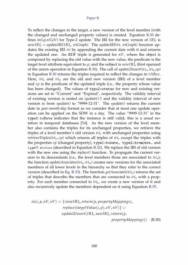
Paper B.
To reflect the changes in the target, a new version of the level member (withthe changed and unchanged property values) is created. Equation B.30 de-fines in(i,p,nV,oV) for Type-2 update. The IRI for the new version of IRIi isnewIRIi = updateIRI(IRIi, iriGraph). The updateIRI(iri, iriGraph) function up-dates the existing IRI iri by appending the current date with it and returnsthe updated one. An RDF triple is generated for nV, where the object iscomposed by replacing the old value with the new value, the predicate is thetarget level attribute equivalent to p, and the subject is newIRIi (first operandof the union operation in Equation B.30). The call of update2Insert(irio, irin,cp)in Equation B.30 returns the triples required to reflect the changes in tABox.Here, irio and irin are the old and new version (IRI) of a level memberand cp is the predicate of the updated triple (i.e., the property whose valuehas been changed). The values of type2:status for new and existing ver-sions are set to “Current" and “Expired", respectively. The validity intervalof existing version is ended on sysdate()-1 and the validity interval of newversion is from sysdate() to “9999-12-31". The sysdate() returns the currentdate in year-month-day format as we consider that at most one update oper-ation can be applied on the SDW in a day. The value “9999-12-31" in thetype2:toDate indicates that the instance is still valid; this is a usual no-tation in temporal databases [54]. As the new version of the level mem-ber also contains the triples for its unchanged properties, we retrieve thetriples of a level member’s old version irio with unchanged properties usingretrieveTriples(irio, cp) which returns all triples of irio except the triples withthe properties cp (changed property), type2:toDate, type2:fromDate, andtype2:status (described in Equation B.32). We replace the IRI of old versionwith the new one using the replace() function. To propagate the current ver-sion to its descendants (i.e., the level members those are associated to irio);the function updateAssociates(irio, irin) creates new versions for the associatedmembers of all lower levels in the hierarchy so that they refer to the correctversion (described in Eq. B.33). The function getAssociates(irio) returns the setof triples that describe the members that are connected to irio with a prop-erty. For each member connected to irio, we create a new version of it andalso recursively update the members dependent on it using Equation B.35.
in(i, p, nV, oV) = {(newIRIi, return(p, propertyMappings),
replace(targetValue(i, p), oV, nV)} ∪update2Insert(IRIi, newIRIi, return(p,
propertyMappings)) (B.30)
180
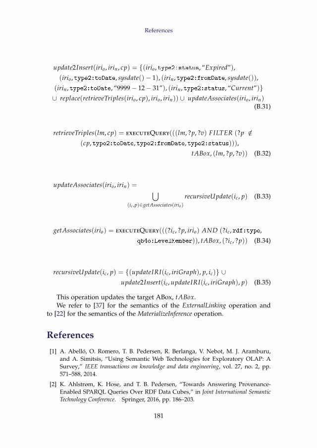
References
update2Insert(irio, irin, cp) = {(irio, type2:status, “Expired”),
(irio, type2:toDate, sysdate()− 1), (irin, type2:fromDate, sysdate()),
(irin, type2:toDate, “9999− 12− 31”), (irin, type2:status, “Current”)}∪ replace(retrieveTriples(irio, cp), irio, irin)) ∪ updateAssociates(irio, irin)
(B.31)
retrieveTriples(lm, cp) = executeQuery(((lm, ?p, ?v) FILTER (?p /∈(cp, type2:toDate, type2:fromDate, type2:status))),
tABox, (lm, ?p, ?v)) (B.32)
updateAssociates(irio, irin) = ⋃(ic ,p)∈getAssociates(irio)
recursiveUpdate(ic, p) (B.33)
getAssociates(irio) = executeQuery(((?ic, ?p, irio) AND (?ic, rdf:type,
qb4o:LevelMember)), tABox, (?ic, ?p)) (B.34)
recursiveUpdate(ic, p) = {(updateIRI(ic, iriGraph), p, ic)} ∪update2Insert(ic, updateIRI(ic, iriGraph), p) (B.35)
This operation updates the target ABox, tABox.We refer to [37] for the semantics of the ExternalLinking operation and
to [22] for the semantics of the MaterializeInference operation.
References
[1] A. Abelló, O. Romero, T. B. Pedersen, R. Berlanga, V. Nebot, M. J. Aramburu,and A. Simitsis, “Using Semantic Web Technologies for Exploratory OLAP: ASurvey,” IEEE transactions on knowledge and data engineering, vol. 27, no. 2, pp.571–588, 2014.
[2] K. Ahlstrøm, K. Hose, and T. B. Pedersen, “Towards Answering Provenance-Enabled SPARQL Queries Over RDF Data Cubes,” in Joint International SemanticTechnology Conference. Springer, 2016, pp. 186–203.
181
References
[3] A. B. Andersen, N. Gür, K. Hose, K. A. Jakobsen, and T. B. Pedersen, “Pub-lishing Danish Agricultural Government Data as Semantic Web Data,” in JointInternational Semantic Technology Conference. Springer, 2014, pp. 178–186.
[4] F. Baader, D. Calvanese, D. McGuinness, P. Patel-Schneider, and D. Nardi, TheDescription Logic Handbook: Theory, Implementation and Applications. Cambridgeuniversity press, 2003.
[5] S. K. Bansal, “Towards a Semantic Extract-Transform-Load (ETL) Framework forBig Data Integration,” in Big Data, 2014, pp. 522–529.
[6] L. Bellatreche, S. Khouri, and N. Berkani, “Semantic Data Warehouse Design:From ETL to Eeployment A La Carte,” in International Conference on DatabaseSystems for Advanced Applications. Springer, 2013, pp. 64–83.
[7] R. Berlanga, O. Romero, A. Simitsis, V. Nebot, T. Pedersen, A. Abelló Gamazo,and M. J. Aramburu, “Semantic Web Technologies for Business Intelligence,”2011.
[8] M. Casters, R. Bouman, and J. Van Dongen, Pentaho Kettle Solutions: Building OpenSource ETL Solutions with Pentaho Data Integration. John Wiley & Sons, 2010.
[9] C. Ciferri, R. Ciferri, L. Gómez, M. Schneider, A. Vaisman, and E. Zimányi, “CubeAlgebra: A Generic User-centric Model and Query Language for OLAP Cubes,”International Journal of Data Warehousing and Mining (IJDWM), vol. 9, no. 2, pp.39–65, 2013.
[10] D. Colazzo, F. Goasdoué, I. Manolescu, and A. Roatis, “RDF Aanalytics: Lensesover Semantic Graphs,” in WWW. ACM, 2014, pp. 467–478.
[11] P. Cudré-Mauroux, “Leveraging Knowledge Graphs for Big Data Integration: theXI Pipeline,” Semantic Web, no. Preprint, pp. 1–5.
[12] R. Cyganiak, D. Reynolds, and J. Tennison, “The RDF Data Cube Vocabulary,”W3C Recommendation, W3C (Jan. 2014), 2014.
[13] R. P. Deb Nath, K. Hose, T. B. Pedersen, O. Romero, and A. Bhattacharjee,“SETLBI: An Integrated Platform for Semantic Business Intelligence,” in Com-panion Proceedings of the Web Conference 2020, 2020, pp. 167–171.
[14] A. Dimou, M. Vander Sande, P. Colpaert, R. Verborgh, E. Mannens, and R. Van deWalle, “RML: a generic language for integrated RDF mappings of heterogeneousdata,” 2014.
[15] L. Etcheverry, S. S. Gomez, and A. Vaisman, “Modeling and Querying DataCubes on the Semantic Web,” arXiv preprint arXiv:1512.06080, 2015.
[16] L. Etcheverry, A. Vaisman, and E. Zimányi, “Modeling and Querying Data Ware-houses on the Semantic Web Using QB4OLAP,” in DaWak, 2014, pp. 45–56.
[17] L. Galárraga, K. Ahlstrøm, K. Hose, and T. B. Pedersen, “Answering Provenance-Aware Queries on RDF Data Cubes under Memory Budgets,” in InternationalSemantic Web Conference. Springer, 2018, pp. 547–565.
[18] L. Galárraga, K. A. M. Mathiassen, and K. Hose, “QBOAirbase: The EuropeanAir Quality Database as an RDF Cube,” in International Semantic Web Conference(Posters, Demos & Industry Tracks), 2017.
182
References
[19] N. Gür, J. Nielsen, K. Hose, and T. B. Pedersen, “GeoSemOLAP: GeospatialOLAP on the Semantic Web made easy,” in Proceedings of the 26th InternationalConference on World Wide Web Companion, 2017, pp. 213–217.
[20] N. Gür, T. B. Pedersen, E. Zimányi, and K. Hose, “A Foundation for Spatial DataWarehouses on the Semantic web,” Semantic Web, vol. 9, no. 5, pp. 557–587, 2018.
[21] S. Harris, A. Seaborne, and E. Prud’hommeaux, “SPARQL 1.1 Query Language,”W3C recommendation, vol. 21, no. 10, 2013.
[22] A. Harth, K. Hose, and R. Schenkel, Linked Data Management. CRC Press, 2014.
[23] O. Hartig, K. Hose, and J. F. Sequeda, “Linked Data Management.” 2019.
[24] T. Heath and C. Bizer, “Linked Data: Evolving the Web into a Global Data Space,”Synthesis lectures on the semantic web: theory and technology, vol. 1, no. 1, pp. 1–136,2011.
[25] M. Hilal, C. G. Schuetz, and M. Schrefl, “An OLAP Endpoint for RDF DataAnalysis Using Analysis Graphs.” in ISWC, 2017.
[26] D. Ibragimov, K. Hose, T. B. Pedersen, and E. Zimányi, “Towards ExploratoryOLAP over Linked Open Data–A Case Study,” in Enabling Real-Time BusinessIntelligence. Springer, 2014, pp. 114–132.
[27] ——, “Processing aggregate queries in a federation of sparql endpoints,” in Eu-ropean Semantic Web Conference. Springer, 2015, pp. 269–285.
[28] ——, “Optimizing aggregate sparql queries using materialized rdf views,” inInternational Semantic Web Conference. Springer, 2016, pp. 341–359.
[29] K. A. Jakobsen, A. B. Andersen, K. Hose, and T. B. Pedersen, “Optimizing rdfdata cubes for efficient processing of analytical queries.” in COLD, 2015.
[30] E. Kalampokis, B. Roberts, A. Karamanou, E. Tambouris, and K. A. Tarabanis,“Challenges on Developing Tools for Exploiting Linked Open Data Cubes.” inSemStats@ ISWC, 2015.
[31] B. Kämpgen, S. O’Riain, and A. Harth, “Interacting with Statistical Linked Datavia OLAP Operations,” in Extended Semantic Web Conference. Springer, 2012, pp.87–101.
[32] R. Kimball, The Data Warehouse Toolkit: Practical Techniques for Building DimensionalData Warehouses. John Wiley & Sons, Inc., 1996.
[33] T. Knap, P. Hanecák, J. Klímek, C. Mader, M. Necasky, B. Van Nuffelen, andP. Škoda, “UnifiedViews: An ETL Tool for RDF Data Management,” SemanticWeb, vol. 9, no. 5, pp. 661–676, 2018.
[34] E. V. Kostylev, J. L. Reutter, and M. Ugarte, “CONSTRUCT Queries in SPARQL,”in 18th International Conference on Database Theory (ICDT 2015). Schloss Dagstuhl-Leibniz-Zentrum fuer Informatik, 2015.
[35] J. Li, J. Tang, Y. Li, and Q. Luo, “Rimom: A Dynamic Multistrategy Ontol-ogy Alignment Framework,” IEEE Transactions on Knowledge and data Engineering,vol. 21, no. 8, pp. 1218–1232, 2008.
183
References
[36] R. P. D. Nath, K. Hose, and T. B. Pedersen, “Towards a Programmable Seman-tic Extract-Transform-Load Framework for Semantic Data Warehouses,” in AcmEighteenth International Workshop on Data Warehousing and Olap (dolap 2015). As-sociation for Computing Machinery, 2015.
[37] R. P. D. Nath, K. Hose, T. B. Pedersen, and O. Romero, “SETL: A ProgrammableSemantic Extract-Transform-Load Framework for Semantic Data Warehouses,”Information Systems, vol. 68, pp. 17–43, 2017.
[38] R. P. D. Nath, H. Seddiqui, and M. Aono, “Resolving Scalability Issue to Ontol-ogy Instance Matching in Semantic Web,” in 2012 15th International Conference onComputer and Information Technology (ICCIT). IEEE, 2012, pp. 396–404.
[39] R. P. D. Nath, M. H. Seddiqui, and M. Aono, “An Efficient and Scalable Approachfor Ontology Instance Matching,” JCP, vol. 9, no. 8, pp. 1755–1768, 2014.
[40] V. Nebot and R. Berlanga, “Building Data Warehouses with Semantic Web Data,”Decision Support Systems, vol. 52, no. 4, pp. 853–868, 2012.
[41] D. Pedersen, J. Pedersen, and T. B. Pedersen, “Integrating XML Data in the TAR-GIT OLAP System,” in Proceedings. 20th International Conference on Data Engineer-ing. IEEE, 2004, pp. 778–781.
[42] D. Pedersen, K. Riis, and T. B. Pedersen, “Query Optimization for OLAP-XMLFederations,” in Proceedings of the 5th ACM international workshop on Data Ware-housing and OLAP, 2002, pp. 57–64.
[43] J. Pérez, M. Arenas, and C. Gutierrez, “Semantics and Complexity of SPARQL,”in International semantic web conference, vol. 4273. Springer, 2006, pp. 30–43.
[44] I. Petrou and G. Papastefanatos, “Publishing Greek Census Data as linked opendata,” ERCIM News, vol. 96, 2014.
[45] A. Polleres, A. Hogan, R. Delbru, and J. Umbrich, “RDFS and OWL Reason-ing for Linked Data,” in Reasoning Web. Semantic Technologies for Intelligent DataAccess. Springer, 2013, pp. 91–149.
[46] E. Prud, A. Seaborne et al., “SPARQL Query Language for RDF,” 2006.
[47] L. Richardson and S. Ruby, RESTful Web Services. " O’Reilly Media, Inc.", 2008.
[48] J. Rouces, G. De Melo, and K. Hose, “Heuristics for Connecting HeterogeneousKnowledge via FrameBase,” in European Semantic Web Conference. Springer, 2016,pp. 20–35.
[49] ——, “FrameBase: Enabling Integration of Heterogeneous Knowledge,” SemanticWeb, vol. 8, no. 6, pp. 817–850, 2017.
[50] M. H. Seddiqui, S. Das, I. Ahmed, R. P. D. Nath, and M. Aono, “Augmentationof Ontology Instance Matching by Automatic Weight Generation,” in Informationand Communication Technologies (WICT), 2011 World Congress on. IEEE, 2011, pp.1390–1395.
[51] J. F. Sequeda and D. P. Miranker, “Ultrawrap: SPARQL execution on relationaldata,” Journal of Web Semantics, vol. 22, pp. 19–39, 2013.
[52] D. Skoutas and A. Simitsis, “Ontology-Based Conceptual Design of ETL Pro-cesses for both Structured and Semi-structured Data,” IJSWIS, vol. 3, no. 4, pp.1–24, 2007.
184
References
[53] M. Thenmozhi and K. Vivekanandan, “An Ontological Approach to Handle Mul-tidimensional Schema Evolution for Data Warehouse,” International Journal ofDatabase Management Systems, vol. 6, no. 3, p. 33, 2014.
[54] A. Vaisman and E. Zimányi, Data Warehouse Systems: Design and Implementation.Springer, 2014.
[55] J. Varga, A. A. Vaisman, O. Romero, L. Etcheverry, T. B. Pedersen, and C. Thom-sen, “Dimensional Enrichment of Statistical Linked Open Data,” Journal of WebSemantics, vol. 40, pp. 22–51, 2016.
[56] X. Yin and T. B. Pedersen, “Evaluating XML-Extended OLAP Queries Based onPhysical Algebra,” Journal of Database Management (JDM), vol. 17, no. 2, pp. 85–116, 2006.
185

References
186
Paper C
SETLBI: An Integrated Platform for SemanticBusiness Intelligence
Rudra Pratap Deb Nath, Katja Hose, Torben Bach Pedersen,Oscar Romero, and Amrit Bhattacharjee
The paper has been published in theWWW’20: Companion Proceedings of the Web Conference 2020
pp. 167–171, 2020. DOI: https://doi.org/10.1145/3366424.3383533
Abstract
With the growing popularity of Semantic Web technologies, more and more orga-nizations natively manage data using Semantic Web standards, in particular RDF.This development gives rise to new requirements for Business Intelligence tools toenable analyses in the style of On-Line Analytical Processing (OLAP) over RDFdata. In this demonstration, we therefore present the SETLBI (Semantic Extract-Transform-Load and Business Intelligence) integration platform that brings togetherthe Semantic Web and Business Intelligence technologies. SETLBI covers all phasesof integration: target definition, source to target mappings generation, semantic andnon-semantic source extraction, data transformation, and target population and up-date. It facilitates Data Warehouse designers to build a semantic Data Warehouse,either from scratch or by defining a multi-dimensional view over existing RDF datasources, and further enables OLAP-style analyses.
c© 2020 IW3C2 (International World Wide Web Conference Committee), pub-lished under Creative Commons CC-BY 4.0 License. Reprinted, with permis-sion from Rudra Pratap Deb Nath, Katja Hose, Torben Bach Pedersen, OscarRomero and Amrit Bhattacharjee. SETLBI : An Integrated Platform for Se-mantic Business Intelligence. In: WWW’20: Companion Proceedings of the WebConference 2020pp. 167–171, 2020. DOI: https://doi.org/10.1145/3366424.3383533The layout has been revised.
1. Introduction
1 Introduction
Business Intelligence tools allow integrating and analyzing data from mul-tiple sources to facilitate business decisions, often in the style of On-LineAnalytical Processing (OLAP). The integrated data are organized in a DataWarehouse, typically designed following the Multidimensional Model (MD),which represents data in terms of facts and dimensions. As source data canbe structured, semi-structured, unstructured, or semantic, it is important toconsider semantic issues in the integration process, which is typically ig-nored by traditional (RDBMS-centric) data integration tools [1]. On the otherhand, initiatives such as Open Government Data (https://opengovdata.org/) encourage organizations to publish their data using standards and non-proprietary formats [16]. Semantic Web standards fulfill these needs as theyallow adding semantics on both data and schema level in the integration pro-cess and publish data in RDF using Linked Data principles [5]. To bridge thisgap, we present SETLBI , a tool that combines Semantic Web and BusinessIntelligence technologies to define, process, integrate, and query semanticdata.
In the remainder of this paper, we refer to a semantically annotated DataWarehouse as a semantic DW and represent it as a knowledge base in RDFcomposed of two components: ABox and TBox [12]. The TBox defines a do-main in terms of concepts, properties, and terminological axioms whereasthe ABox consists of assertions of the TBox. To define the expressivity of theknowledge base with MD semantics, SETLBI uses the Data Cube (QB) [4] andQB4OLAP [6] vocabularies. In doing so, we can elegantly define a TBox withessential Data Warehouse concepts, such as cube structures, dimensions, lev-els, level attributes, OLAP operations, and complex hierarchies. On the otherhand, SETLBI also allows to enrich the TBox with RDFS/OWL classes andproperties. To create the ABox from (non-)semantic sources, we introducea set of basic semantic ETL operations that can be connected and pipelinedto orchestrate an ETL flow from the data sources to the semantic DW. Finally,SETLBI provides an interactive interface to enable self-service OLAP analysisover the semantic DW.
In summary, SETLBI enables (i) users with a background in Data Ware-housing but little-to-no background in Semantic Web technologies to seman-tically integrate semantic and/or non-semantic data and analyze it in OLAP-style, and (ii) users with basic background in Semantic Web and Data Ware-house technologies to define multidimensional views over semantic data andrun OLAP-like analysis. Additionally, users can enrich the generated TBoxwith RDFS and OWL constructs.
189
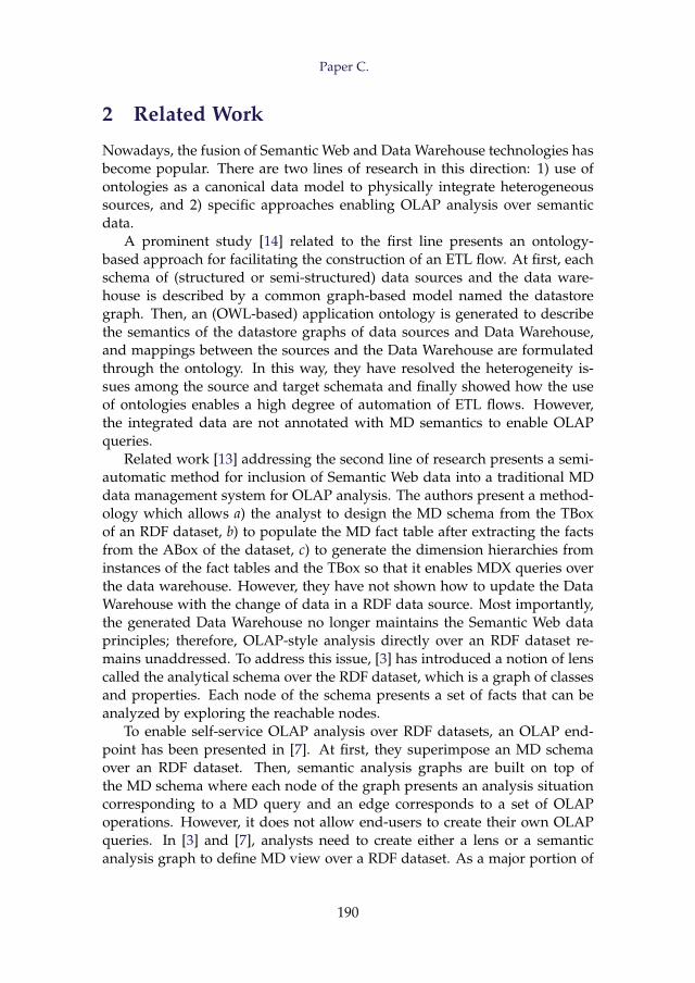
Paper C.
2 Related Work
Nowadays, the fusion of Semantic Web and Data Warehouse technologies hasbecome popular. There are two lines of research in this direction: 1) use ofontologies as a canonical data model to physically integrate heterogeneoussources, and 2) specific approaches enabling OLAP analysis over semanticdata.
A prominent study [14] related to the first line presents an ontology-based approach for facilitating the construction of an ETL flow. At first, eachschema of (structured or semi-structured) data sources and the data ware-house is described by a common graph-based model named the datastoregraph. Then, an (OWL-based) application ontology is generated to describethe semantics of the datastore graphs of data sources and Data Warehouse,and mappings between the sources and the Data Warehouse are formulatedthrough the ontology. In this way, they have resolved the heterogeneity is-sues among the source and target schemata and finally showed how the useof ontologies enables a high degree of automation of ETL flows. However,the integrated data are not annotated with MD semantics to enable OLAPqueries.
Related work [13] addressing the second line of research presents a semi-automatic method for inclusion of Semantic Web data into a traditional MDdata management system for OLAP analysis. The authors present a method-ology which allows a) the analyst to design the MD schema from the TBoxof an RDF dataset, b) to populate the MD fact table after extracting the factsfrom the ABox of the dataset, c) to generate the dimension hierarchies frominstances of the fact tables and the TBox so that it enables MDX queries overthe data warehouse. However, they have not shown how to update the DataWarehouse with the change of data in a RDF data source. Most importantly,the generated Data Warehouse no longer maintains the Semantic Web dataprinciples; therefore, OLAP-style analysis directly over an RDF dataset re-mains unaddressed. To address this issue, [3] has introduced a notion of lenscalled the analytical schema over the RDF dataset, which is a graph of classesand properties. Each node of the schema presents a set of facts that can beanalyzed by exploring the reachable nodes.
To enable self-service OLAP analysis over RDF datasets, an OLAP end-point has been presented in [7]. At first, they superimpose an MD schemaover an RDF dataset. Then, semantic analysis graphs are built on top ofthe MD schema where each node of the graph presents an analysis situationcorresponding to a MD query and an edge corresponds to a set of OLAPoperations. However, it does not allow end-users to create their own OLAPqueries. In [3] and [7], analysts need to create either a lens or a semanticanalysis graph to define MD view over a RDF dataset. As a major portion of
190
3. System Architecture
the published (statistical) Linked Data contains facts and figures, W3C rec-ommends QB [4] vocabulary as a standard to describe data in a MD fashion.
[10] has investigated OLAP operations on a single data cube publishedwith QB vocabulary and shown the applicability of their OLAP-to-SPARQLmapping in answering business questions. Although QB is appropriate topublish statistical data, it has limitations to represent MD semantics prop-erly. QB4OLAP [6] extends QB by providing constructs to define a dimen-sion structure (in terms of levels, the relationship between the levels, andhierarchies of the dimension), a cube structure in terms of different levelsof dimensions, measures, and attaching aggregate functions with measures.In [15] and [16], the authors presented a method to semi-automatically enrichthe QB dataset with QB4OLAP constructs. However, to run OLAP queries us-ing the OLAP interface of their system, it requires end users to be familiarwith either QL [2] or complex SPARQL queries.
[8, 9] has proposed a set of query processing strategies for executingOLAP-like SPARQL queries over a federation of SPARQL endpoints. Here,they use QB4OLAP constructs to annotate the conceptual global schema withMD semantics. However, participating sources in a federation might be un-available at some point. Data and schemata of the sources might have evolvedsince the federation was created; thus, integration rules might no longer bevalid or history of the data will be lost. Therefore, the standard approach isto avoid federation and have a local copy of the data which is the focus ofthis research.
The related approaches discussed in this section address one or moreparts of our aimed problem, but there is no single solution that supportsall the steps (target definition, mappings, ETL generation, target population,evolution and update) necessary to integrate heterogeneous data semanti-cally in a semantic DW and enabling OLAP queries on it. SETLBI bridgesthe two lines of research by defining the TBox of a semantic DW with MD se-mantics using QB and QB4OLAP constructs, providing RDF-based semanticintegration operations to populate/evolve/update the ABox of the semanticDW from heterogeneous sources and allowing users to create OLAP queriesby using different MD constructs of the semantic DW.
3 System Architecture
The data integration process using SETLBI requires the following steps: 1)defining a target TBox with MD semantics using QB and QB4OLAP con-structs, 2) generating mappings from sources to target, 3) populating the tar-get ABox from the available data sources, and 4) issuing OLAP queries on thesemantic DW. Based on the integration steps, we organize SETLBI into threelayers: the Definition Layer, ETL Layer, and OLAP Layer, see in Figure C.1.
191
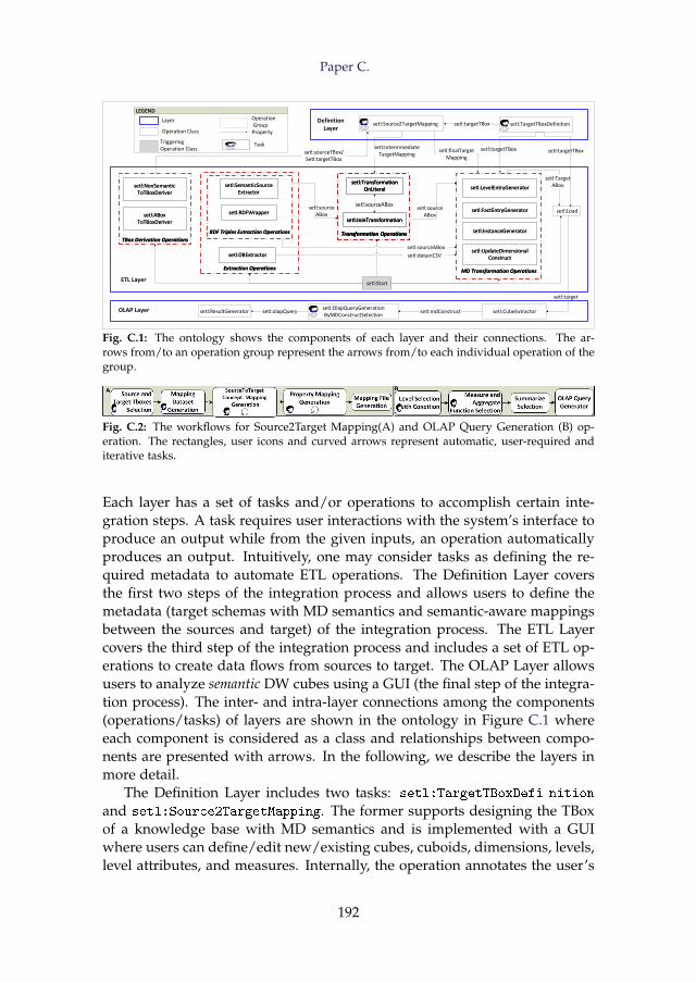
Paper C.
setl:Load
setl:Start
setl:TargetTBoxDefinition setl:Source2TargetMapping setl:targetTBox
ETL Layer
Definition Layer
setl:targetTBoxsetl:sourceTBox/Setl:targetTBox
OLAP Layer setl:CubeExtractorsetl:OlapQueryGenerationByMDConstructSelection
setl:ResultGenerator setl:mdConstruct
setl:target
setl:TargetABox
setl:olapQuery
setl:targetTBox
setl:NonSemanticToTBoxDeriver
setl:ABoxToTBoxDeriver
TBox Derivation Operations
setl:NonSemanticToTBoxDeriver
setl:ABoxToTBoxDeriver
TBox Derivation Operations
setl:LevelEntryGenerator
setl:FactEntryGenerator
setl:InstanceGenerator
setl:UpdateDimensionalConstruct
MD Transformation Operations
setl:LevelEntryGenerator
setl:FactEntryGenerator
setl:InstanceGenerator
setl:UpdateDimensionalConstruct
MD Transformation Operations
LEGEND
Operation Class
Layer
Triggering Operation Class
Property
Task
setl:TransformationOnLiteral
setl:JoinTransformation
Transformation Operations
setl:TransformationOnLiteral
setl:JoinTransformation
Transformation Operations
setl:sourceABox
setl:TransformationOnLiteral
setl:JoinTransformation
Transformation Operations
setl:sourceABox
setl:RDFWrapper
setl:SemanticSourceExtractor
Extraction Operations
setl:DBExtractor
RDF Triples Extraction Operations
setl:RDFWrapper
setl:SemanticSourceExtractor
Extraction Operations
setl:DBExtractor
RDF Triples Extraction Operations
setl:sourceABox
setl:sourceABox
setl:datainCSV
setl:finalTargetMapping
setl:IntermmediateTargetMapping
setl:sourceABox
Operation Group
Fig. C.1: The ontology shows the components of each layer and their connections. The ar-rows from/to an operation group represent the arrows from/to each individual operation of thegroup.
Fig. C.2: The workflows for Source2Target Mapping(A) and OLAP Query Generation (B) op-eration. The rectangles, user icons and curved arrows represent automatic, user-required anditerative tasks.
Each layer has a set of tasks and/or operations to accomplish certain inte-gration steps. A task requires user interactions with the system’s interface toproduce an output while from the given inputs, an operation automaticallyproduces an output. Intuitively, one may consider tasks as defining the re-quired metadata to automate ETL operations. The Definition Layer coversthe first two steps of the integration process and allows users to define themetadata (target schemas with MD semantics and semantic-aware mappingsbetween the sources and target) of the integration process. The ETL Layercovers the third step of the integration process and includes a set of ETL op-erations to create data flows from sources to target. The OLAP Layer allowsusers to analyze semantic DW cubes using a GUI (the final step of the integra-tion process). The inter- and intra-layer connections among the components(operations/tasks) of layers are shown in the ontology in Figure C.1 whereeach component is considered as a class and relationships between compo-nents are presented with arrows. In the following, we describe the layers inmore detail.
The Definition Layer includes two tasks: setl:TargetTBoxDefi nition
and setl:Source2TargetMapping. The former supports designing the TBoxof a knowledge base with MD semantics and is implemented with a GUIwhere users can define/edit new/existing cubes, cuboids, dimensions, levels,level attributes, and measures. Internally, the operation annotates the user’s
192
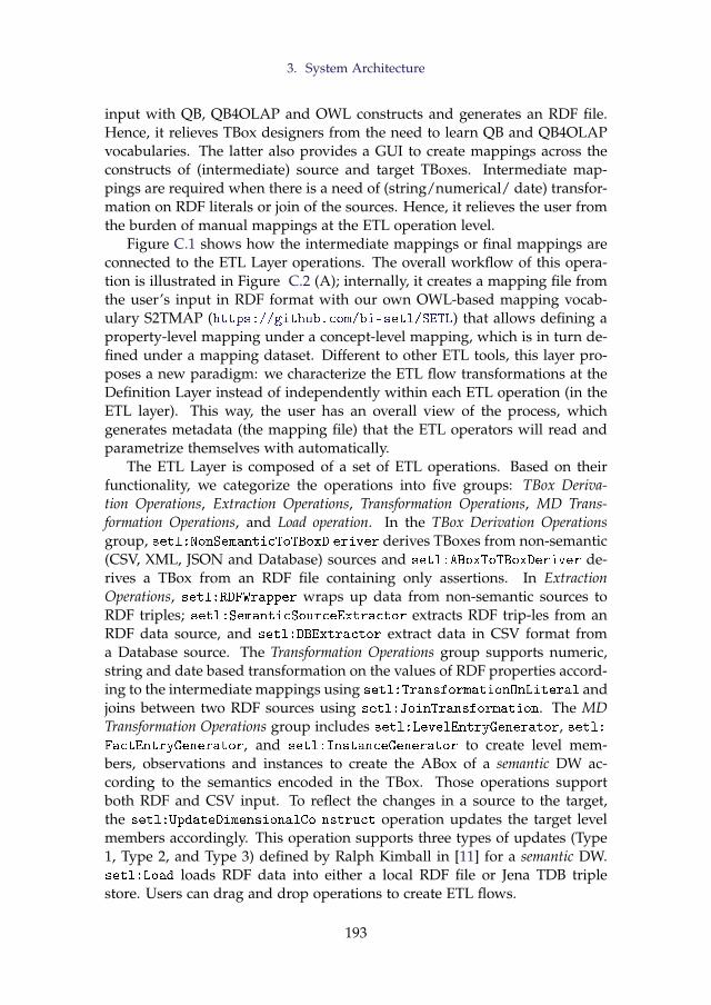
3. System Architecture
input with QB, QB4OLAP and OWL constructs and generates an RDF file.Hence, it relieves TBox designers from the need to learn QB and QB4OLAPvocabularies. The latter also provides a GUI to create mappings across theconstructs of (intermediate) source and target TBoxes. Intermediate map-pings are required when there is a need of (string/numerical/ date) transfor-mation on RDF literals or join of the sources. Hence, it relieves the user fromthe burden of manual mappings at the ETL operation level.
Figure C.1 shows how the intermediate mappings or final mappings areconnected to the ETL Layer operations. The overall workflow of this opera-tion is illustrated in Figure C.2 (A); internally, it creates a mapping file fromthe user’s input in RDF format with our own OWL-based mapping vocab-ulary S2TMAP (https://github.com/bi-setl/SETL) that allows defining aproperty-level mapping under a concept-level mapping, which is in turn de-fined under a mapping dataset. Different to other ETL tools, this layer pro-poses a new paradigm: we characterize the ETL flow transformations at theDefinition Layer instead of independently within each ETL operation (in theETL layer). This way, the user has an overall view of the process, whichgenerates metadata (the mapping file) that the ETL operators will read andparametrize themselves with automatically.
The ETL Layer is composed of a set of ETL operations. Based on theirfunctionality, we categorize the operations into five groups: TBox Deriva-tion Operations, Extraction Operations, Transformation Operations, MD Trans-formation Operations, and Load operation. In the TBox Derivation Operationsgroup, setl:NonSemanticToTBoxD eriver derives TBoxes from non-semantic(CSV, XML, JSON and Database) sources and setl:ABoxToTBoxDeriver de-rives a TBox from an RDF file containing only assertions. In ExtractionOperations, setl:RDFWrapper wraps up data from non-semantic sources toRDF triples; setl:SemanticSourceExtractor extracts RDF trip-les from anRDF data source, and setl:DBExtractor extract data in CSV format froma Database source. The Transformation Operations group supports numeric,string and date based transformation on the values of RDF properties accord-ing to the intermediate mappings using setl:TransformationOnLiteral andjoins between two RDF sources using setl:JoinTransformation. The MDTransformation Operations group includes setl:LevelEntryGenerator, setl:FactEntryGenerator, and setl:InstanceGenerator to create level mem-bers, observations and instances to create the ABox of a semantic DW ac-cording to the semantics encoded in the TBox. Those operations supportboth RDF and CSV input. To reflect the changes in a source to the target,the setl:UpdateDimensionalCo nstruct operation updates the target levelmembers accordingly. This operation supports three types of updates (Type1, Type 2, and Type 3) defined by Ralph Kimball in [11] for a semantic DW.setl:Load loads RDF data into either a local RDF file or Jena TDB triplestore. Users can drag and drop operations to create ETL flows.
193
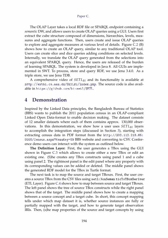
Paper C.
The OLAP Layer takes a local RDF file or SPARQL endpoint containing asemantic DW, and allows users to create OLAP queries using a GUI. Users firstextract the cube structure composed of dimensions, hierarchies, levels, mea-sures and aggregate functions. Then, users create and issue OLAP queriesto explore and aggregate measures at various level of details. Figure C.2 (B)shows how to create an OLAP query, similar to any traditional OLAP tool.Users can create slice and dice queries adding conditions on selected levels.Internally, we translate the OLAP query generated from the selections intoan equivalent SPARQL query. Hence, the users are released of the burdenof learning SPARQL. The system is developed in Java 8. All GUIs are imple-mented in SWT. To process, store and query RDF, we use Jena 3.4.0. As atriple store, we use Jena TDB.
A comprehensive video of SETLBI and its functionality is available athttp://extbi.cs.aau.dk/SETLBI/index.php. The source code is also avail-able in https://github.com/bi-setl/SETL.
4 Demonstration
Inspired by the Linked Data principles, the Bangladesh Bureau of Statistics(BBS) wants to publish the 2011 population census in an OLAP-compliantLinked Open Data-format to enable decision making. The dataset consistsof 12 smaller datasets where each of them contains approx. 130,000 obser-vations. In this demonstration, we show how a user uses SETLBI layersto accomplish the integration steps (discussed in Section 3), starting withextracting census data in PDF format from the http://203.112.218.65:
8008/Census.aspx?MenuKey=89 BBS website and converting to CSV. Confer-ence demo users can interact with the system as outlined below.
The Definition Layer: First, the user generates a TBox using the GUIshown in Figure C.3 which allows to create either a new TBox or edit anexisting one. (S)he creates any TBox constructs using panel 1 and a cubeusing panel 2. The rightmost panel is the edit panel where any property withits corresponding values can be added or deleted. The middle panel showsthe generated RDF model for the TBox in Turtle format.
The next task is to map the source and target TBoxes. First, the user cre-ates a source TBox from the CSV files using setl:NonSeman ticToTBoxDeriver
(ETL Layer). Figure C.4 shows how to map between source and target TBoxes.The left panel shows the tree of source TBox constructs while the right panelshows that of the target. The middle panel shows how to create a mappingbetween a source concept and a target cube. In short, this concept mappingtells under which map dataset it is, whether source instances are fully orpartially mapped with the target, and how to generate target observationIRIs. Then, (s)he map properties of the source and target concepts by using
194
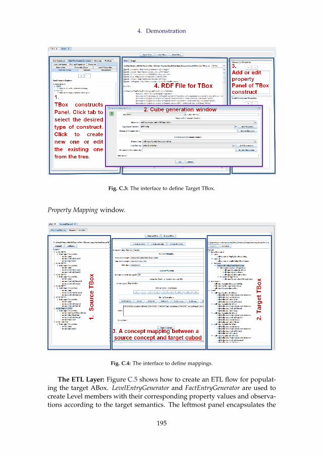
4. Demonstration
Fig. C.3: The interface to define Target TBox.
Property Mapping window.
Fig. C.4: The interface to define mappings.
The ETL Layer: Figure C.5 shows how to create an ETL flow for populat-ing the target ABox. LevelEntryGenerator and FactEntryGenerator are used tocreate Level members with their corresponding property values and observa-tions according to the target semantics. The leftmost panel encapsulates the
195
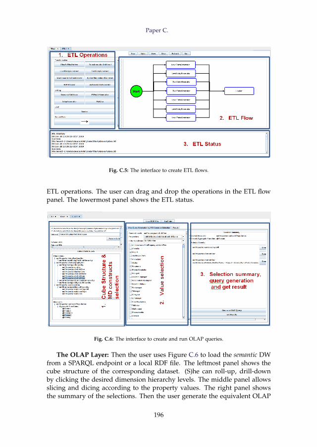
Paper C.
Fig. C.5: The interface to create ETL flows.
ETL operations. The user can drag and drop the operations in the ETL flowpanel. The lowermost panel shows the ETL status.
Fig. C.6: The interface to create and run OLAP queries.
The OLAP Layer: Then the user uses Figure C.6 to load the semantic DWfrom a SPARQL endpoint or a local RDF file. The leftmost panel shows thecube structure of the corresponding dataset. (S)he can roll-up, drill-downby clicking the desired dimension hierarchy levels. The middle panel allowsslicing and dicing according to the property values. The right panel showsthe summary of the selections. Then the user generate the equivalent OLAP
196
References
query and finally click Get Result to show the result panel.
Acknowledgements
This research is partially funded by the European Commission through theErasmus Mundus Joint Doctorate Information Technologies for Business In-telligence (EM IT4BI-DC), the Poul Due Jensen Foundation, and the DanishCouncil for Independent Research (DFF) under grant agreement no. DFF-4093-00301B.
References
[1] A. Abelló, O. Romero, T. B. Pedersen, R. Berlanga, V. Nebot, M. J. Aramburu,and A. Simitsis, “Using Semantic Web Technologies for Exploratory OLAP: ASurvey,” IEEE TKDE, vol. 27, no. 2, pp. 571–588, 2014.
[2] C. Ciferri, R. Ciferri, L. Gómez, M. Schneider, A. Vaisman, and E. Zimányi, “Cubealgebra: A Generic User-Centric Model and Query Language for OLAP Cubes,”IJDWM, vol. 9, no. 2, pp. 39–65, 2013.
[3] D. Colazzo, F. Goasdoué, I. Manolescu, and A. Roatis, “RDF Analytics: Lensesover Semantic Graphs,” in WWW. ACM, 2014, pp. 467–478.
[4] R. Cyganiak, D. Reynolds, and J. Tennison, “The RDF Data Cube Vocabulary,”W3C Recommendation, W3C (Jan. 2014), 2014.
[5] R. P. Deb Nath, K. Hose, and T. B. Pedersen, “Towards a Programmable SemanticExtract-Transform-Load Framework for Semantic Data Warehouses,” in Proceed-ings of the ACM Eighteenth International Workshop on Data Warehousing and OLAP,2015, pp. 15–24.
[6] L. Etcheverry and A. A. Vaisman, “QB4OLAP: A New Vocabulary for OLAPCubes on The Semantic Web,” COLD, 2012.
[7] M. Hilal, C. G. Schuetz, and M. Schrefl, “An OLAP Endpoint for RDF DataAnalysis Using Analysis Graphs.” in ISWC, 2017.
[8] D. Ibragimov, K. Hose, T. B. Pedersen, and E. Zimányi, “Towards ExploratoryOLAP over Linked Open Data–A Case Study,” in Enabling Real-Time BusinessIntelligence. Springer, 2014, pp. 114–132.
[9] D. Ibragimov, K. Hose, T. B. Pedersen, and E. Zimányi, “Processing AggregateQueries in a Federation of SPARQL Endpoints,” in ESWC, vol. 9088, 2015, pp.269–285.
[10] B. Kämpgen, S. O’Riain, and A. Harth, “Interacting with Statistical Linked Datavia OLAP Operations,” in ESWC. Springer, 2012, pp. 87–101.
[11] R. Kimball, The data warehouse toolkit: practical techniques for building dimensionaldata warehouses. John Wiley & Sons, Inc., 1996.
197
References
[12] R. P. D. Nath, K. Hose, T. B. Pedersen, and O. Romero, “SETL: A ProgrammableSemantic Extract-Transform-Load Framework for Semantic Data Warehouses,”Information Systems, vol. 68, pp. 17–43, 2017.
[13] V. Nebot and R. Berlanga, “Building Data Warehouses with Semantic Web Data,”Decision Support Systems, vol. 52, no. 4, pp. 853–868, 2012.
[14] D. Skoutas and A. Simitsis, “Ontology-Based Conceptual Design of ETL Pro-cesses for Both Structured and Semi-Structured Data,” IJSWIS, vol. 3, no. 4, pp.1–24, 2007.
[15] J. Varga, L. Etcheverry, A. A. Vaisman, O. Romero, T. B. Pedersen, and C. Thom-sen, “QB2OLAP: Enabling OLAP on Statistical Linked Open Data,” in ICDE.IEEE, 2016, pp. 1346–1349.
[16] J. Varga, A. A. Vaisman, O. Romero, L. Etcheverry, T. B. Pedersen, and C. Thom-sen, “Dimensional Enrichment of Statistical Linked Open Data,” Web Semantics:Science, Services and Agents on the World Wide Web, vol. 40, pp. 22–51, 2016.
198
Paper D
Towards a Programmable SemanticExtract-Transform-Load Framework for Semantic
Data Warehouses
Rudra Pratap Deb Nath, Katja Hose, and Torben Bach Pedersen
The paper has been published in theProceedings of the ACM Eighteenth International Workshop on Data Warehousing
and OLAPpp. 15–24, 2015. DOI: http://dx.doi.org/10.1145/2811222.2811229
Abstract
In order to create better decisions for business analytics, organizations increasinglyuse external data, structured, semi-structured and unstructured, in addition to the(mostly structured) internal data. Current Extract-Transform-Load (ETL) tools arenot suitable for this “open world scenario” because they do not consider semanticissues in the integration process. Also, current ETL tools neither support process-ing semantic-aware data nor create a Semantic Data Warehouse (DW) as a semanticrepository of semantically integrated data. This paper describes SETL: a (Python-based) programmable Semantic ETL framework. SETL builds on Semantic Web(SW) standards and tools and supports developers by offering a number of pow-erful modules, classes and methods for (dimensional and semantic) DW constructsand tasks. Thus it supports semantic-aware data sources, semantic integration, andcreating a semantic DW, composed of an ontology and its instances. A comprehen-sive experimental evaluation comparing SETL to a solution made with traditionaltools (requiring much more hand-coding) on a concrete use case, shows that SETLprovides better performance, knowledge base quality and porgrammer productivity.
c© 2015 ACM. Reprinted, with permission from Rudra Pratap Deb Nath,Katja Hose, and Torben Bach Pedersen. Towards a Programmable SemanticExtract-Transform-Load Framework for Semantic Data Warehouses. In: Pro-ceedings of the ACM Eighteenth International Workshop on Data Warehousing andOLAPpp. 15–24, 2015. DOI: http://dx.doi.org/10.1145/2811222.2811229The layout has been revised.
1. Introduction
1 Introduction
Business Intelligence (BI) tools support intelligent business decisions by an-alyzing available organizational data. Data Warehouses (DWs) are used tostore the large data volumes from different operational databases in enter-prises and On-Line Analytical Processing (OLAP) queries are applied onDWs to answer business questions. Extract-Transform-Load (ETL) is thebackbone process of a DW. The strength of a DW depends on how goodits ETL process is. Extraction retrieves data from appropriate data sources.Transformation converts the source data according to the target schema ofthe DW, typically either a star or snowflake schema. Loading stores the trans-formed data into the DW. DW/OLAP technologies perform efficiently whenthey are applied on data that are static in nature and well-organized in struc-ture.
Nowadays, the Web is also an important source of business information.Moreover, Semantic Web (SW) technologies and the Linked Data (LD) prin-ciples inspire organizations to publish their business-related data using theResource Description Framework (RDF) [29]. As a result, besides analyzinginternal data available in a DW, it is often desirable to incorporate externaldata from various (semantic) sources into the DW to derive the needed busi-ness knowledge.
The inclusion of external data, especially RDF data, however, raises sev-eral challenges for integration and transformation in comparison to the tradi-tional ETL process. One of the drawbacks of using RDF data in the corporateanalysis process is that the data sometimes do not have any schema, or onlyhave a poor or complex schema. Moreover, different sources describe thedata in their own way, introducing heterogeneity problems. Therefore, tobuild a successful data warehouse system with these heterogeneous data, theintegration process should emphasize the semantic relationship of the data.Traditional ETL tools are unable to process such external data because they(1) do not support semantic-aware data, (2) are entirely schema-dependent,(3) do not focus on meaningful semantic relationships to integrate data fromdisparate sources [4], and (4) do not support deriving new information byactive inference and reasoning on the data. Thus, a DW with both internaland external (semantic) data requires more powerful tools to define, integrateand transform data semantically.
SW technology was introduced with the vision of converting the ‘Web ofDocuments’ to the ‘Web of Data’ where data are presented and exchanged ina machine-readable and understandable format, and data are integrated witheach other semantically. The journey towards this vision is quite successful,and a number of standards, languages, and tools have been developed toexpress semantic-based metadata. To give a common framework for present-
201
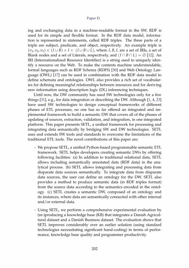
Paper D.
ing and exchanging data in a machine-readable format in the SW, RDF isused for its simple and flexible format. In the RDF data model, informa-tion is represented in statements, called RDF triples. The three parts of atriple are subject, predicate, and object, respectively. An example triple is(v1, v2, v3) ∈ (I ∪ B)× I × (I ∪ B ∪ L), where I, B, L are a set of IRIs, a set ofBlank nodes and a set of Literals, respectively, and (I ∩ B ∩ L) = ∅ [12]. AnIRI (Internationalized Resource Identifier) is a string used to uniquely iden-tify a resource on the Web. To make the contents machine understandable,formal languages such as RDF Schema (RDFS) [30] and Web Ontology Lan-guage (OWL) [17] can be used in combination with the RDF data model todefine schemata and ontologies. OWL also provides a rich set of vocabular-ies for defining meaningful relationships between resources and for derivingnew information using description logic (DL) inferencing techniques.
Until now, the DW community has used SW technologies only for a fewthings [31], e.g., for data integration or describing the DW. Although [1, 4, 23]have used SW technologies to design conceptual frameworks of differentphases of ETL processes, no one has so far offered an integrated and im-plemented framework to build a semantic DW that covers all of the phases ofupdating of sources, extraction, validation, and integration, in one integratedplatform. This paper presents SETL, a unified framework for processing andintegrating data semantically by bridging SW and DW technologies. SETLuses and extends SW tools and standards to overcome the limitations of thetraditional ETL tools. The novel contributions of this paper are:
- We propose SETL, a unified Python-based programmable semantic ETLframework. SETL helps developers creating semantic DWs by offeringfollowing facilities: (a) In addition to traditional relational data, SETLallows including semantically annotated data (RDF data) in the ana-lytical process. (b) SETL allows integrating and processing data fromdisparate data sources semantically. To integrate data from disparatedata sources, the user can define an ontology for the DW. SETL alsoprovides a method to produce semantic data (in RDF triples format)from the source data according to the semantics encoded in the ontol-ogy. (c) SETL creates a semantic DW, composed of an ontology andits instances, where data are semantically connected with other internaland/or external data.
- Using SETL, we perform a comprehensive experimental evaluation by(re-)producing a knowledge base (KB) that integrates a Danish Agricul-tural dataset and a Danish Business dataset. The evaluation shows thatSETL improves considerably over an earlier solution (using standardtechnologies necessitating significant hand-coding) in terms of perfor-mance, knowledge base quality and programmer productivity.
202
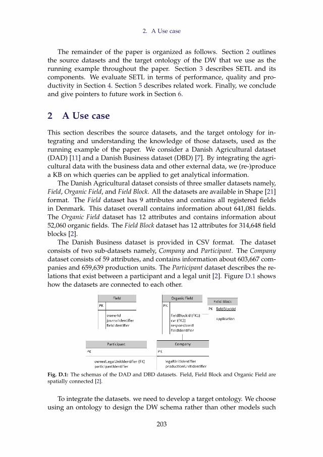
2. A Use case
The remainder of the paper is organized as follows. Section 2 outlinesthe source datasets and the target ontology of the DW that we use as therunning example throughout the paper. Section 3 describes SETL and itscomponents. We evaluate SETL in terms of performance, quality and pro-ductivity in Section 4. Section 5 describes related work. Finally, we concludeand give pointers to future work in Section 6.
2 A Use case
This section describes the source datasets, and the target ontology for in-tegrating and understanding the knowledge of those datasets, used as therunning example of the paper. We consider a Danish Agricultural dataset(DAD) [11] and a Danish Business dataset (DBD) [7]. By integrating the agri-cultural data with the business data and other external data, we (re-)producea KB on which queries can be applied to get analytical information.
The Danish Agricultural dataset consists of three smaller datasets namely,Field, Organic Field, and Field Block. All the datasets are available in Shape [21]format. The Field dataset has 9 attributes and contains all registered fieldsin Denmark. This dataset overall contains information about 641,081 fields.The Organic Field dataset has 12 attributes and contains information about52,060 organic fields. The Field Block dataset has 12 attributes for 314,648 fieldblocks [2].
The Danish Business dataset is provided in CSV format. The datasetconsists of two sub-datasets namely, Company and Participant. The Companydataset consists of 59 attributes, and contains information about 603,667 com-panies and 659,639 production units. The Participant dataset describes the re-lations that exist between a participant and a legal unit [2]. Figure D.1 showshow the datasets are connected to each other.
Fig. D.1: The schemas of the DAD and DBD datasets. Field, Field Block and Organic Field arespatially connected [2].
To integrate the datasets. we need to develop a target ontology. We chooseusing an ontology to design the DW schema rather than other models such
203
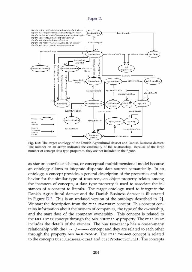
Paper D.
Fig. D.2: The target ontology of the Danish Agricultural dataset and Danish Business dataset.The number on an arrow indicates the cardinality of the relationship. Because of the largenumber of concept data type properties, they are not included in the figure.
as star or snowflake schema, or conceptual multidimensional model becausean ontology allows to integrate disparate data sources semantically. In anontology, a concept provides a general description of the properties and be-havior for the similar type of resources; an object property relates amongthe instances of concepts; a data type property is used to associate the in-stances of a concept to literals. The target ontology used to integrate theDanish Agricultural dataset and the Danish Business dataset is illustratedin Figure D.2. This is an updated version of the ontology described in [2].We start the description from the bus:Ownership concept. This concept con-tains information about the owners of companies, the type of the ownership,and the start date of the company ownership. This concept is related tothe bus:Owner concept through the bus:isOwnedBy property. The bus:Owner
includes the details of the owners. The bus:Ownership has a one-to-manyrelationship with the bus:Company concept and they are related to each otherthrough the property bus:hasCompany. The bus:Company concept is relatedto the concepts bus:BusinessFormat and bus:ProductionUnit. The concepts
204
3. The SETL Framework
bus:Company and bus:ProductionUnit are also related to the bus:Activity
concept through one main activity and/or through one-three secondary ac-tivities. Each company and each production unit have a postal address andan official address. Therefore, both concepts are related with the bus:Addressconcept. Each address is positioned at an address feature, which is, in turn,contained within a particular municipality. The bus:Company concept is alsorelated to the concept bus:OrganicField through the relation bus:owns aseach company may contain one or more organic field. By this relation, thebusiness and agricultural datasets are connected. The bus:Field conceptcontains all the registered agricultural fields of Denmark. Thus, bus:OrganicField is a subclass of bus:Field. The bus:Field is also equivalent to theUN definition of a European field. A field produces a crop. A field is con-tained within a field block. Each field block has an application. The conceptsbus:AddressFeature, bus:Municipality, agri:Field, agri:FieldBlock aredefined as subclasses of the GeoNames:Feature concept in the GeoNamesontology.
3 The SETL Framework
In this section, we present our Semantic ETL framework (SETL in short) thatwe implemented in Python. Our discussion focuses on SETL’s architectureand its main methods that support the different phases of a semantic ETLprocess and produce a semantic data warehouse based on RDF triples. Themain phases are: defining a target ontology based on the domain of interest,extracting data from multiple heterogeneous data sources, transforming thesource data into RDF triples according to the target ontology, and loadingthe data into a triple store, and/or publishing the data on the Web as LinkedData.
Figure D.3 illustrates how SETL’s components are connected to each other.SETL follows a demand-driven approach, i.e., a data warehouse is designedby identifying the information requirements of users and decision makers [5].Based on the requirements, an ontology describing the relevant data and thetarget data warehouse can be defined using the Ontology Definition module.The Define Mapping module is used to define the mappings between the datasources and the target ontology. The Extraction module then extracts datafrom multiple sources, the Traditional Transformation module cleanses and for-mats the extracted data, and the Semantic Transformation converts the datainto RDF triples according to the target ontology. The External Linking mod-ule links the resources in the created RDF dataset to other external resources.Finally, the Writing module can write the created RDF dataset into a file ondisk and the Loading module can directly load the created RDF dataset into atriple store, which can directly be queried by the user. The following sections
205
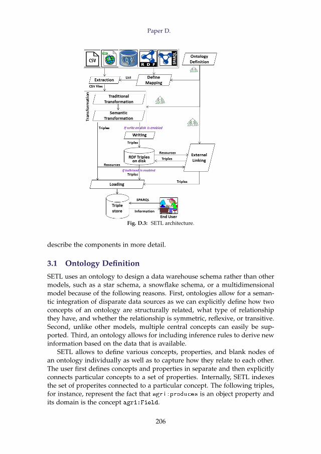
Paper D.
Fig. D.3: SETL architecture.
describe the components in more detail.
3.1 Ontology Definition
SETL uses an ontology to design a data warehouse schema rather than othermodels, such as a star schema, a snowflake schema, or a multidimensionalmodel because of the following reasons. First, ontologies allow for a seman-tic integration of disparate data sources as we can explicitly define how twoconcepts of an ontology are structurally related, what type of relationshipthey have, and whether the relationship is symmetric, reflexive, or transitive.Second, unlike other models, multiple central concepts can easily be sup-ported. Third, an ontology allows for including inference rules to derive newinformation based on the data that is available.
SETL allows to define various concepts, properties, and blank nodes ofan ontology individually as well as to capture how they relate to each other.The user first defines concepts and properties in separate and then explicitlyconnects particular concepts to a set of properties. Internally, SETL indexesthe set of properites connected to a particular concept. The following triples,for instance, represent the fact that agri:produces is an object property andits domain is the concept agri:Field.
206
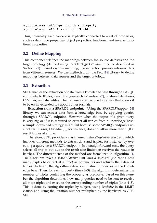
3. The SETL Framework
agri:produces rdf:type owl:objectProperty.
agri:produces rdfs:Domain agri:Field.
Thus, internally each concept is explicitly connected to a set of properties,such as data type properties, object properties, functional and inverse func-tional properties.
3.2 Define Mapping
This component defines the mappings between the source datasets and thetarget ontology (defined using the Ontology Definition module described inSection 3.1). Based on this mapping, the extraction process retrieves datafrom different sources. We use methods from the Petl [18] library to definemappings between data sources and the target ontology.
3.3 Extraction
SETL enables the extraction of data from a knowledge base through SPARQLendpoints, RDF files, a search engine such as Sindice [27], relational databases,CSV files, and shapefiles. The framework is designed in a way that allows itto be easily extended to support other formats.
Extraction from a SPARQL endpoint. Using the SPARQLWrapper [24]library, we can extract data from a knowledge base by applying queriesthrough a SPARQL endpoint. However, when the output of a given queryis very big or if it is required to extract all triples from a knowledge base,a simple download strategy might fail because some SPARQL endpoints re-strict result sizes; DBpedia [8], for instance, does not allow more than 10,000result triples at a time.
Therefore, SETL provides a class named ExtractTriplesFromEndpoint whichincludes different methods to extract data and triples, for instance, by exe-cuting a query on a SPARQL endpoint. In a straightforward case, the queryselects all triples but due to the result size limitation receives the results inbatches. The different steps of the method are formalized in Algorithm 11.The algorithm takes a sparqlEndpoint URL and a batchsize (indicating howmany triples to extract at a time) as parameters and returns the extractedtriples. In line 1, the algorithm extracts all distinct properties in the knowl-edge base. Then, for each property (lines 2–3), the algorithm determines thenumber of triples containing the property as predicate. Based on this num-ber the algorithm determines how many queries need to be sent to receiveall these triples and executes the corresponding number of triples (lines 4–5).This is done by sorting the triples by subject, using batchsize in the LIMITclause, and using the iteration number multiplied by the batchsize as OFF-SET.
207
Paper D.
Algorithm 11: TripleExtraction.Input: endpoint, batchsizeOutput: triplesetbegin
1 P = retrieveDistinctProperty(endpoint)2 foreach property p ∈ P do3 x = retrieveNumberO f Triples(p, endpoint);4 for count← 0 to x/batchsize do5 tripleset+ = retrieveTriples(count, batchsize, endpoint);
6 return tripleset
Extraction from an RDF file. We use the RDFLib library [20] to execute aquery on a local RDF file. If the RDF file is too large to fit into main memory,we split the file into several smaller files, execute the query on the smallerfiles, and then combine the partial results. However, this method can only beused for simply queries, such as retrieving all triples with a particular pred-icate. More complex queries involving joins need to be handled differently,e.g., by loading the data into a local SPARQL endpoint first and using themethod described in the previous paragraph.
Extraction using semantic search engine. Currently, SETL supportsextraction using the Sindice [27] search engine. To do so, the user provides akeyword or resource name that we want to retrieve information for. Based onthis, SETL retrieves a list of relevant resource URLs from Sindice. The usercan then manually select a list of URLs which are then used to retrieve triplesinvolving them.
Extraction from a relational database or a CSV file. SETL is based onPetl [18], which is a traditional ETL Python package including a rich set ofmethods to perform extraction, cleansing, and transformation based on rela-tional databases and CSV files. Making use of these methods, SETL providesthe functionality as well.
Extraction from a shapefile. A shapefile [21] is a file format that storesgeometric location and attribute information of geographic features in vec-tor format. Points, lines, and polygons can be used to describe a geographicfeature. To read data from a shapefile, we use the pyshape [19] library. Inter-nally, SETL can store the data of a shapefile either in a file or in a databasetable. SETL provides methods to automatically create a table in a databasebased on the structure of a shapefile and to insert the data from the shape-file into the created table. It also provides a method to store the attributeinformation of a shapefile in CSV format.
Figure D.1 shows that there is no direct connection between Field andOrganicField, neither between Field and FieldBlock. In the target ontology
208
3. The SETL Framework
(Figure D.2), however, we have defined connections, e.g., agri:Field andagri:OrganicField are connected through the owl:sameAs property andagri:FieldBlock and agri:Field are connected via the agri:contains prop-erty. These connections are computed based on a spatial join that SETLcomputes during the extraction process for pairs of shapefiles. We use theArcPy [3] library to perform the spatial join analysis.
3.4 Transformation
We divide the transformation tasks into two categories: Traditional Transfor-mation and Semantic Transformation. Traditional Transformation includes op-erations known from traditional ETL tools, such as cleansing the data andformatting the source data according to the target schema. This includesremoving duplicate data, normalizing data, renaming attributes, checkingintegrity constraints, refining data, creating new attributes based on existingattributes, sorting data, and grouping data [4]. SETL is using the Petl [18]library to implement the above mentioned operations.
Semantic Transformation includes operations to create RDF triples accord-ing to the target ontology based on the data output by the Traditional Trans-formation component. To perform this task, SETL provides two methods:createTriples and trickleLoad. The createTriples method transforms the data intotriples and writes them to disk. Afterwards, the bulkload methods (discussedin Section 3.6) can be used to load the data into a triple store. The trickleLoadmethod converts the cleansed and transformed data into triples and subse-quently loads them into a triple store holding the triples in main memory.The core mechanism of creating RDF triples creation is sketched in Algo-rithm 12.
Algorithm 12 describes the steps of converting a relational table (table)into a set of RDF triples (T). As additional input, the algorithm needs thename of an attribute in the table (resourceKey) that can be used to uniquelyidentify each row. In addition, its value will be used to create resource iden-tifiers. At first, a dictionary D is created based on the input table (line 1). Dconsists of (key, value) pairs for each row r in table; the key corresponds tor’s resourceKey value. The value in turn corresponds to a list of (attribute,value) pairs where each pair represents one of r’s cells. The next step is todetermine which concepts in the target ontology the information containedin the table correspond to (line 2). Based on this information, the algorithmruns through each such concept c. Some tables in relational databases do notdirectly correspond to a concept, instead they represent many-to-many rela-tionships between instances of concepts (entity types). Hence, only for thosetables that directly correspond to a concept, the algorithm creates a new re-source for each entry in the dictionary and a triple (with rdf:type as predi-cate) that defines the new resource as an instance of the concept (lines 5–6).
209
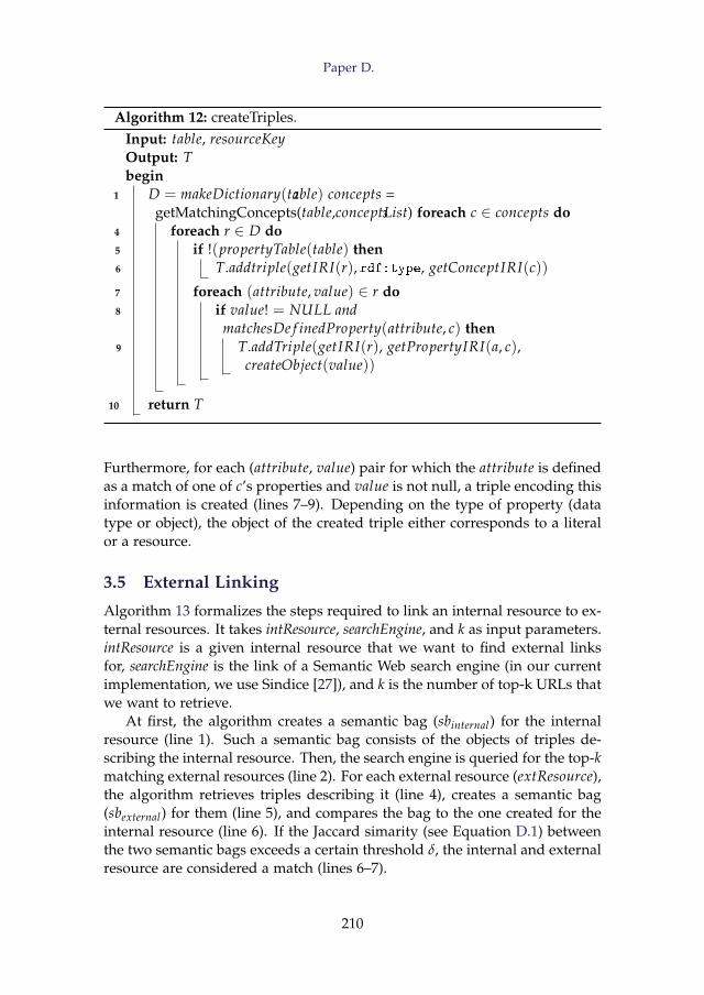
Paper D.
Algorithm 12: createTriples.Input: table, resourceKeyOutput: Tbegin
1 D = makeDictionary(table)2 concepts =getMatchingConcepts(table,conceptList)3 foreach c ∈ concepts do
4 foreach r ∈ D do5 if !(propertyTable(table) then6 T.addtriple(getIRI(r), rdf:type, getConceptIRI(c))
7 foreach (attribute, value) ∈ r do8 if value! = NULL and
matchesDe f inedProperty(attribute, c) then9 T.addTriple(getIRI(r), getPropertyIRI(a, c),
createObject(value))
10 return T
Furthermore, for each (attribute, value) pair for which the attribute is definedas a match of one of c’s properties and value is not null, a triple encoding thisinformation is created (lines 7–9). Depending on the type of property (datatype or object), the object of the created triple either corresponds to a literalor a resource.
3.5 External Linking
Algorithm 13 formalizes the steps required to link an internal resource to ex-ternal resources. It takes intResource, searchEngine, and k as input parameters.intResource is a given internal resource that we want to find external linksfor, searchEngine is the link of a Semantic Web search engine (in our currentimplementation, we use Sindice [27]), and k is the number of top-k URLs thatwe want to retrieve.
At first, the algorithm creates a semantic bag (sbinternal) for the internalresource (line 1). Such a semantic bag consists of the objects of triples de-scribing the internal resource. Then, the search engine is queried for the top-kmatching external resources (line 2). For each external resource (extResource),the algorithm retrieves triples describing it (line 4), creates a semantic bag(sbexternal) for them (line 5), and compares the bag to the one created for theinternal resource (line 6). If the Jaccard simarity (see Equation D.1) betweenthe two semantic bags exceeds a certain threshold δ, the internal and externalresource are considered a match (lines 6–7).
210
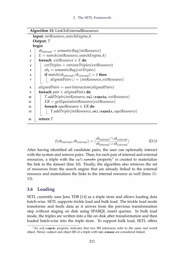
3. The SETL Framework
Algorithm 13: LinkToExternalResources.Input: intResource, searchEngine, kOutput: Tbegin
1 sbinternal = semanticBag(intResource)2 E = search(intResource, searchEngine, k)3 foreach extResource ∈ E do4 extTriples = retrieveTriples(extResource)5 sb2 = semanticBag(extTriples)6 if match(sbinternal , sbexternal) > δ then7 alignedPairs∪ = (intResource, extResource)
8 alignedPairs = userInteraction(alignedPairs)9 foreach pair ∈ alignedPairs do
10 T.addTriple(intResource, owl:sameAs, extResource)11 ER = getEquivalentResource(extResource)12 foreach equiResource ∈ ER do13 T.addTriple(intResource, owl:sameAs, equiResource)
14 return T
J(sbinternal , sbexternal) = |sbinternal ∩ sbexternalsbinternal ∪ sbexternal
| (D.1)
After having identified all candidate pairs, the user can optionally interactwith the system and remove pairs. Then, for each pair of internal and externalresources, a triple with the owl:sameAs property1 is created to materializethe link in the dataset (line 10). Finally, the algorithm also retrieves the setof resources from the search engine that are already linked to the externalresource and materializes the links to the internal resource as well (lines 11-13).
3.6 Loading
SETL currently uses Jena TDB [14] as a triple store and allows loading databatch-wise. SETL supports trickle load and bulk load. The trickle load modetransforms and feeds data as it arrives from the previous transformationstep without staging on disk using SPARQL insert queries. In bulk loadmode, the triples are written into a file on disk after transformation and thenloaded batch-wise into the triple store. To support bulk load, SETL offers
1An owl:sameAs property indicates that two IRI references refer to the same real worldobject. Hence, subject and object IRI of a triple with owl:sameAs are considered linked.
211
Paper D.
two methods: bulkTDBLoader (tdblocation, filePath, batchsize) and bulkSPAR-QLInsert(tdblocation, filePath, batchsize, database). The BulkTDBLoader is used toload data from a file on disk into a triple store using the TDBLoader. The pa-rameter tdblocation denotes the location of a TDB database, the filePath is thepath to the triple file, and batchsize is the number of triples to be fed into thestore at a time. The BulkSPARQLInsert is similar to BulkTDBLoader but definesSPARQL insert statements to load triples instead of using the TDBLoader. Itadditionally requires the name of the database as parameter.
4 Evaluation
To evaluate SETL, we applied the proposed ETL process on sources coveringDanish agricultural and business information. We chose this use case andthese datasets for evaluation as there exists an RDF dataset based on thesesources [2] that has been created in a manual process by using a broad rangeof different tools. In contrast, SETL allows to perform this process mostlyautomatically with minimal user interaction. This allows us to compare thedifferent ETL processes as well as the RDF datasets themselves. In the follow-ing, we refer to the dataset published by [2] as ExtBIKB and the one createdby SETL as SETLKB. Our evaluation concentrates on three aspects: the timerequired to run the processes, quality of the produced datasets, and produc-tivity, i.e., to what extent SETL eases the work of a user when performing anETL task to produce RDF datasets.
We run the experiment on a HP ProLiant DL385 server with an AMDOpteron(tm) processor 6376 with 32 cores (only 1 core is used in the experi-ments); it has 256 GB DDR3 RAM and is running Ubuntu 14.04.1 LTS (TrustyTahr). The data is stored on an 1-TB SCSI disk running in an HP Smart Array.
4.1 Performance
In this section, we discuss the time required for different sub-processes tocreate SETLKB using SETL and the performance of different loading meth-ods.
Runtime of the different phases. Figure D.4 illustrates the time thateach phase of the ETL process requires; the figure shows both the time foreach phase in separate and the overall runtime of the complete process. Thetimes represent averages over 5 test runs. As SETL automatically connects allthe phases, the end time of one phase becomes the starting time of the next.Figure D.4 also shows the materialized output of each phase.
The Extraction and Traditional Transformation phases take a relatively longtime because they involve performing two spatial join operations for the agri-culture datasets. The Semantic Transformation process is time-intensive be-
212
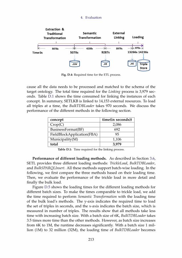
4. Evaluation
Fig. D.4: Required time for the ETL process.
cause all the data needs to be processed and matched to the schema of thetarget ontology. The total time required for the Linking process is 3,979 sec-onds. Table D.1 shows the time consumed for linking the instances of eachconcept. In summary, SETLKB is linked to 14,153 external resources. To loadall triples at a time, the BulkTDBLoader takes 970 seconds. We discuss theperformance of the different methods in the following section.
concept time(in seconds))Crop(C) 2,086BusinessFormat(BF) 692FieldBlockApplication(FBA) 95Municipality(M) 1,106total 3,979
Table D.1: Time required for the linking process.
Performance of different loading methods. As described in Section 3.6,SETL provides three different loading methods: TrickleLoad, BulkTDBLoader,and BulkSPARQLInsert. All these methods support batch-wise loading. In thefollowing, we first compare the three methods based on their loading time.Then, we evaluate the performance of the trickle load in more detail andfinally the bulk load.
Figure D.5 shows the loading times for the different loading methods fordifferent batch sizes. To make the times comparable to trickle load, we addthe time required to perform Semantic Transformation with the loading timeof the bulk load’s methods. The y-axis indicates the required time to loadthe set of triples in seconds, and the x-axis indicates the batch size, which ismeasured in number of triples. The results show that all methods take lesstime with increasing batch size. With a batch size of 6K, BulkTDBLoader takes3.5 times more time than the other methods. However, as batch size increasesfrom 6K to 1M, the runtime decreases significantly. With a batch size 1 mil-lion (1M) to 32 million (32M), the loading time of BulkTDBLoader becomes
213
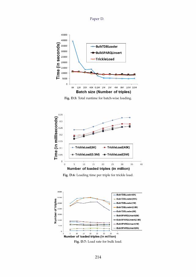
Paper D.
Fig. D.5: Total runtime for batch-wise loading.
Fig. D.6: Loading time per triple for trickle load.
Fig. D.7: Load rate for bulk load.
214
4. Evaluation
nearly stable and BulkTDBLoader becomes two times faster than other twomethods. This is because TDBLoader is especially implemented for loadingbig files; therefore, it performs better with larger batch sizes. On the otherhand, TrickleLoad is slightly better than BulkSPARQLInsert in all cases. Thisis because BulkSPARQLInsert reads the triples from disk, where TrickleLoaduses memory as intermediate storage. In this experiment, we find that allmethods take lowest time to load with a batch size of 16M. In summary, werecommend BulkTDBLoader for large files and BulkSPARQLInsert for smallerfiles. Trickle load is preferable when concurrent processing and loading isrequired.
Figure D.6 illustrates the time trickle load requires to load increasingnumbers of triples. Here, the lines indicate different batch sizes. We cal-culate the time t = T/N, where T is the total time required to load N triples.The figure shows that with the increase in the number of loaded triples, thetime increases almost linearly. For the trickle loads with the base sizes 6Kand 40K, the constant startup cost is 10 million triples.
Figure D.7 shows the loading rate in terms of the number of triples loadedper second (TPS) for different batch sizes of the bulk load. The figure showsthat with an increasing number of loaded triples, TPS increases until a certainpoint for BulkTDBLoader. After that point, TPS decreases with the increase inthe number of loaded triples. This is mainly because of the internal indexingstrategy of Jena TDB [14]. It also depends on the size of the triples to beloaded. On the other hand, for BulkSPARQLInsert, the number of triples persecond gently decreases with the an increase in the number of loaded triples.
4.2 Quality
In this section, we examine the extent to which the produced triples are con-sistent, complete, interpretable, fresh, and semantically linked [26]. We com-pare the result created with SETL (SETLKB) to ExtBIKB.
Consistency. According to the definition, an object property relates in-stances of two classes, i.e, if x is a value of an object property, there mustexist at least one triple whose subject is x. We found out that for a sig-nificant number of values for the object properties bus:postalAddress andbus:officialAddress, ExtBIKB does not contain such information. Thereare 83,302 bus:officialAddresses and 34 bus:postalAddresses that arenot used as a subject of any triple in ExtBIKB. In SETLKB, on the other hand,all bus:officialAddresses and bus:postalAddresses have correctly beenrelated to the bus:Address concept. Hence, data consistency is completelymaintained in SETLKB.
Information loss. In ExtBIKB, fields that do not produce any crop arenot represented. This affects 2,650 instances of the concept agri:Field. Sim-ilarly, instances of agri:OrganicField that have the value “999999-99” for
215
Paper D.
the agri:FieldBlock property are not represented in ExtBIKB. This affects1,213 instances. For SETLKB on the contrary, we do not want to miss anyagri:Field or agri:OrganicFields instance even though they do not havecrop information. Hence, in the cleansing step, we replace the value “999999-99” with NULL. If an instance of a concept contains NULL or an unknownvalue for a property, the createTriples method (described in Section 3.4) simplydoes not produce a triple for that property. This is how SETLKB ensures datacompleteness.
In the original raw datasets, we can find out since when a legal unit be-longs to an owner. This is not possible in ExtBIKB if an owner owns morethan one company. We fixed this issue by extending the target ontology.In addition, we also add the information related to the type of the owner,i.e., whether the owner is a person or another company, both are missing inExtBIKB.
Furthermore, the main and secondary activity of a company or produc-tion unit are treated as the same activity in the ExtBIKB. In SETLKB, the con-cepts bus:Company and bus:ProductionUnit are connected to bus:Activity
through two object properties: bus:hasMainAcitivity and bus:hasSecondar
yActivity. Thus, SETLKB provides more information than ExtBIKB.Redundant triples. If a property is inversely connected to another prop-
erty, then storing the same types of triples for both properties, simply byinterchanging the subject and predicate of the triples, makes a KB redun-dant. The properties bus:belongsTo and bus:hasProductionUnit are in-versely connected to each other and relate the concepts bus:Company andbus:ProductionUnit. In ExtBIKB, triples are stored for both properties sep-arately, which produces extra 659,639 triples. On the other hand, we createtriples only for bus:belongsTo property. Hence, SETLKB reduces redun-dancy.
External linking. We enhance our knowledge base by linking it toother external resources at instance level. Section 3.5 describes the linkingprocess. We run the linking process only for instances of agri:Crop (C),agri:FieldBlockApplication (FBA), bus:BusinessFormat (BF), and bus:Mu
nicipality (M) because for instances of other concepts, Sindice [27] does notcontain relevant information. Note that the following results are produced bythe automatic matching process without any pre-filtering by the user (whichis mentioned as an optional step in Section 3.5). Table D.2 shows the differenttypes of concepts for which we run the linking process, their total numberof instances, the number of internal instances linked to external resources,the number of external resources connected to an internal instance, and theaccuracy rate of the linking.
In total, 202 instances of SETLKB are linked to 14,153 external resources.To evaluate the linking process, we randomly chose 5% of the triples thatlinked internal and external resources and manually evaluated their correct-
216
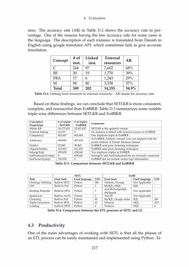
4. Evaluation
ness. The accuracy rate (AR) in Table D.2 shows the accuracy rate in per-centage. One of the reasons having the low accuracy rate for some cases isthe language. The description of each instance is translated from Danish toEnglish using google translator API, which sometimes fails to give accuratetranslation.
Concept# ofinst.
Linkedinst.
Externalresources
AR
C 244 97 7,602 68%BF 30 19 1,770 39%FBA 17 6 1,243 29%M 98 80 3,538 57%Total 389 202 14,153 54.9%
Table D.2: Linking local resources to external resources – AR stands for accuracy rate.
Based on these findings, we can conclude that SETLKB is more consistent,complete, and resourceful than ExtBIKB. Table D.3 summarizes some notabletriple-wise differences between SETLKB and ExtBIKB.
Concept(c)/Property(p)
# of triplesSETLKB
# of triplesExtBIKB
Comments
Whole KB 34,177,652 32,457,657 SETLKB is the updated version.External linking 14,153 0 No instance is linked with external sources in ExtBIKB.Company(c) 603,667 603,668 One duplicate triple in ExtBIKB.
Address(c) 499,850 497,938In ExtBIKB, Address concept were not mapped with thepostal address of Danish Business dataset.
Field(c) 52,060 50,842 ExtBIKB used poor cleansing techniques.OrganicField(c) 613,903 611,093 ExtBIKB used poor cleansing techniques.belongsTo(p) 659,638 659,640 Two duplicate triples in ExtBIKB.hasProductionUnit(p) 0 659,640 belongsTo and hasProductionUnit are inversely connected.hasOwnerType(p) 353,954 0 ExtBIKB did not include owner type information.
Table D.3: Comparison between SETLKB and ExtBIKB
SETL ExtBITask Used tools Used language LOC Used tools Used language LOCOntology Defining Built-in SETL Python 286 Virtuoso, Protege Not Applicable -CSV Build-in Petl Python 2 MySQL,vtSQL SQL -
Reading Shapefile Build-in SETL Python 3ArcGIS,PostgreSQL,shp2pgsql
Not Applicable -
Spatial join Built-in ArcPy Python 2 ArcGIS Not Applicable -Cleansing Built-in Petl Python 85 MySQL, Google refine SQL 360Triple Generation Built-in SETL Python 61 Virtuoso iSQL 1511Loading build-in SETL Python 4 Virtuoso iSQL 4
Table D.4: Comparison between the ETL processs of SETL and [2]
4.3 Productivity
One of the main advantages of working with SETL is that all the phases ofan ETL process can be easily maintained and implemented using Python. Ta-
217
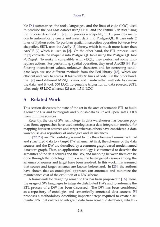
Paper D.
ble D.4 summarizes the tools, languages, and the lines of code (LOC) usedto produce the SETLKB dataset using SETL and the ExtBIKB dataset usingthe process described in [2]. To process a shapefile, SETL provides meth-ods to automatically create and insert data into PostgreSQL. It uses only 2lines of Python code. To perform spatial intersection operation between twoshapefiles, SETL uses the ArcPy [3] library, which is much more faster thanArcGIS [9] which is used in [2]. On the other hand, the ETL process usedin [2] converts the shapefile into PostgreSQL table using the PostgreSQL toolshp2pgsql. To make it compatible with vtSQL, they performed some find-replace actions. For performing, spatial operation, they used ArcGIS [9]. Forfiltering inconsistent values, unknown characters and for correcting candi-date keys, we use different methods from the Petl library [18], which areefficient and easy to access. It takes only 85 lines of code. On the other hand,the [2] used different MySQL views and hand-crafted methods to cleansethe data, and it took 360 LOC. To generate triples for all data sources, SETLtakes only 85 LOC whereas [2] uses 1,511 LOC.
5 Related Work
This section discusses the state of the art in the area of semantic ETL to builda semantic DW and to integrate and publish data as Linked Open Data (LOD)from multiple sources.
Recently, the use of SW technology in data warehouses has become pop-ular. Some approaches have used ontologies as a data integration method formapping between sources and target whereas others have considered a datawarehouse as a repository of ontologies and its instances.
In [22, 23], an OWL ontology is used to link the schemas of semi-structuredand structured data to a target DW schema. At first, the schemas of the datasources and the DW are described by a common graph-based model nameddatastore graph. Then, an application ontology is constructed to describe thesemantics of the data sources and the DW, and mapping between them can bedone through that ontology. In this way, the heterogeneity issues among theschemas of sources and target have been resolved. In this work, it is assumedthat source and target schemas are known beforehand. In [25], the authorshave shown that an ontological approach can automate and minimize themaintenance cost of the evolution of a DW schema.
A framework for designing semantic DW has been proposed in [16]. Here,the usage of SW languages to integrate distributed DWs and to automate theETL process of a DW has been discussed. The DW has been consideredas a repository of ontologies and semantically annotated data sources. [5]proposes a methodology describing important steps required to create a se-mantic DW that enables to integrate data from semantic databases, which is
218
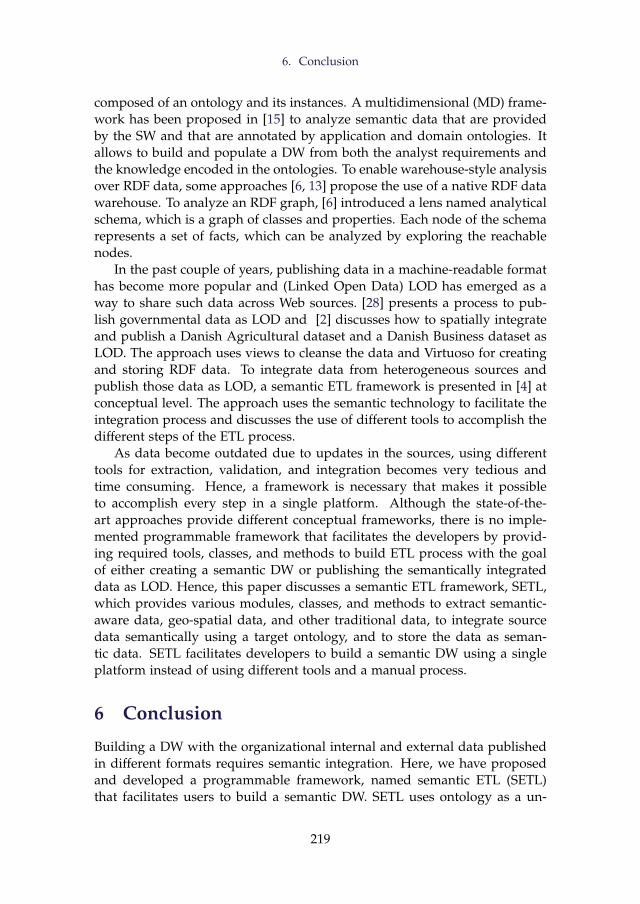
6. Conclusion
composed of an ontology and its instances. A multidimensional (MD) frame-work has been proposed in [15] to analyze semantic data that are providedby the SW and that are annotated by application and domain ontologies. Itallows to build and populate a DW from both the analyst requirements andthe knowledge encoded in the ontologies. To enable warehouse-style analysisover RDF data, some approaches [6, 13] propose the use of a native RDF datawarehouse. To analyze an RDF graph, [6] introduced a lens named analyticalschema, which is a graph of classes and properties. Each node of the schemarepresents a set of facts, which can be analyzed by exploring the reachablenodes.
In the past couple of years, publishing data in a machine-readable formathas become more popular and (Linked Open Data) LOD has emerged as away to share such data across Web sources. [28] presents a process to pub-lish governmental data as LOD and [2] discusses how to spatially integrateand publish a Danish Agricultural dataset and a Danish Business dataset asLOD. The approach uses views to cleanse the data and Virtuoso for creatingand storing RDF data. To integrate data from heterogeneous sources andpublish those data as LOD, a semantic ETL framework is presented in [4] atconceptual level. The approach uses the semantic technology to facilitate theintegration process and discusses the use of different tools to accomplish thedifferent steps of the ETL process.
As data become outdated due to updates in the sources, using differenttools for extraction, validation, and integration becomes very tedious andtime consuming. Hence, a framework is necessary that makes it possibleto accomplish every step in a single platform. Although the state-of-the-art approaches provide different conceptual frameworks, there is no imple-mented programmable framework that facilitates the developers by provid-ing required tools, classes, and methods to build ETL process with the goalof either creating a semantic DW or publishing the semantically integrateddata as LOD. Hence, this paper discusses a semantic ETL framework, SETL,which provides various modules, classes, and methods to extract semantic-aware data, geo-spatial data, and other traditional data, to integrate sourcedata semantically using a target ontology, and to store the data as seman-tic data. SETL facilitates developers to build a semantic DW using a singleplatform instead of using different tools and a manual process.
6 Conclusion
Building a DW with the organizational internal and external data publishedin different formats requires semantic integration. Here, we have proposedand developed a programmable framework, named semantic ETL (SETL)that facilitates users to build a semantic DW. SETL uses ontology as a un-
219
References
derlying schema to integrate heterogeneous data sources. Besides traditionaldata format, SETL can process semantic-aware data. Eventually, it stores thedata as RDF triples. It also allows to link the internal resources with ex-ternal resources. In order to evaluate our framework, we (re-)produced aknowledge base by integrating a Danish Agricultural dataset and a DanishBusiness dataset using SETL; then we compared SETL’s KB (SETLKB) anddevelopment process with that of ExtBI. In Section 4, we showed the perfor-mance of our trickle load and bulk load. Comparing to ExtBIKB, SETLKB KBis more consistent, informative and normalized. SETL also provides betterproductivity than the tools used by ExtBI.
We will augment the Ontology Definition module with QB4OLAP [10] vo-cabularies to enable OLAP-like analysis. Our future research includes auto-matic recommendation of an ontology for integration by analyzing the struc-tures of the given data sources, automatic mapping between sources and tar-get ontology, recommendation of relevant sources, and designing semanticETL operations. We also have a plan to make the GUI version of SETL.
References
[1] A. Abelló, O. Romero, T. B. Pedersen, R. Berlanga, V. Nebot, M. J. Aramburu,and A. Simitsis, “Using Semantic Web Technologies for Exploratory OLAP: ASurvey,” TKDE, vol. 99, pp. 571–588, 2014.
[2] A. B. Andersen, N. Gür, K. Hose, K. A. Jakobsen, and T. B. Pedersen, “PublishingDanish Agricultural Government Data as Semantic Web Data,” in JIST, 2015.
[3] “ArcPy-ArcGIS Python Library, http://help.arcgis.com/en/arcgisdesktop/10.0/help/index.html#//000v00000001000000.”
[4] S. K. Bansal, “Towards a Semantic Extract-Transform-Load (ETL) Framework for Big Data Integration,” in Big Data, 2014, pp. 522–529.
[5] L. Bellatreche, S. Khouri, and N. Berkani, “Semantic Data Warehouse Design:From ETL to Deployment à la Carte,” in DASFAA, 2013, pp. 64–83.
[6] D. Colazzo, F. Goasdoué, I. Manolescu, and A. Roatis, “RDF Analytics: Lensesover Semantic Graphs,” in WWW, 2014, pp. 467–478.
[7] “Danish Central Company Registry (CVR) Data, http://cvr.dk/.”
[8] “DBpedia, http://dbpedia.org/.”
[9] “Esri, Arcgis. http://www.esri.com/software/arcgis.”
[10] L. Etcheverry, A. Vaisman, and E. Zimányi, “Modeling and Querying Data Ware-houses on the Semantic Web Using QB4OLAP,” in DaWak, 2014, pp. 45–56.
[11] “Ministry of Food, Agriculture and Fisheries of Denmark, http://en.fvm.dk/.”
[12] A. Harth, K. Hose, and R. Schenkel, Linked Data Management. CRC Press, 2014.
[13] K. A. Jakobsen, A. B. Andersen, K. Hose, and T. B. Pedersen, “Optimizing RDFData Cubes for Efficient Processing of Analytical Queries,” in COLD, 2015.
220
References
[14] “Apache Jena TDB, https://jena.apache.org/documentation/tdb/.”
[15] V. Nebot and R. Berlanga, “Building Data Warehouses with Semantic Web Data,”DSS, vol. 52, no. 4, pp. 853–868, 2012.
[16] V. Nebot, R. Berlanga, J. M. Pérez, M. J. Aramburu, and T. B. Pedersen, “Multi-dimensional Integrated Ontologies: a Framework for Designing Semantic DataWarehouses,” JDS, vol. XIII, pp. 1–36, 2009.
[17] “OWL Web Ontology Language, www.w3.org/TR/owl-ref/.”
[18] “Petl - Extract, Transform and Load (Tables of Data), https://petl.readthedocs.org/en/latest/.”
[19] “Pyshp, https://code.google.com/p/pyshp/.”
[20] “Rdflib, https://github.com/RDFLib/rdflib.”
[21] “ESRI, Shapefile Technical Description, INC, 1998.”
[22] D. Skoutas and A. Simitsis, “Designing ETL Processes using Semantic Web Tech-nologies,” in DOLAP, 2006, pp. 67–74.
[23] ——, “Ontology-based Conceptual Design of ETL Processes for both Structuredand Semi-structured Data,” IJSWIS, vol. 3, no. 4, pp. 1–24, 2007.
[24] “SPARQLWrapper, http://rdflib.github.io/sparqlwrapper/.”
[25] M. Thenmozhi and K. Vivekanandan, “An Ontological Approach to Handle Mul-tidimensional Schema Evolution for Data Warehouse,” IJDMS, vol. 6, no. 4, pp.33–52, 2014.
[26] V. Theodorou, A. Abelló, and W. Lehner, “Quality Measures for ETL Processes,”in DaWaK, 2014, pp. 9–22.
[27] G. Tummarello, R. Delbru, and E. Oren, “Sindice. com: Weaving the open linkeddata,” in ISWC, 2007.
[28] B. Villazón-Terrazas, L. M. Vilches-Blázquez, O. Corcho, and A. Gómez-Pérez, “AMethodological Guidelines for Publishing Government Linked Data,” in Linkinggovernment data, 2011, pp. 27–49.
[29] “W3C. Resource Description Framework, http://www.w3.org/RDF/.”
[30] “W3C. Resource Description Framework Schema, http://www.w3.org/TR/rdf-schema/.”
[31] M. E. Zorrilla, J.-N. Mazón, Ó. Ferrández, I. Garrigós, F. Daniel, and J. Trujillo,Business Intelligence Applications and the Web: Models, Systems and Technologies.Business Science Reference, 2012.
221

RU
DR
A PRATA
P DEB
NATH
ASPEC
TS OF SEM
AN
TIC ETL
ISSN (online): 2446-1628ISBN (online): 978-87-7210-657-1