aalborg universitet test setup for anechoic room...
TRANSCRIPT
Aalborg Universitet
Test Setup for Anechoic Room based MIMO OTA Testing of LTE Terminals
Carreño, Xavier; Fan, Wei; Nielsen, Jesper Ødum; Ashta, Jagjit; Pedersen, Gert F.; Knudsen,MikaelPublished in:Proc. 7th European Conference on Antenna and Propagation (EUCAP 2013)
Publication date:2013
Document VersionEarly version, also known as pre-print
Link to publication from Aalborg University
Citation for published version (APA):Carreño, X., Fan, W., Nielsen, J. Ø., Ashta, J., Pedersen, G. F., & Knudsen, M. (2013). Test Setup for AnechoicRoom based MIMO OTA Testing of LTE Terminals. In Proc. 7th European Conference on Antenna andPropagation (EUCAP 2013) (pp. 1417 - 1420). IEEE.
General rightsCopyright and moral rights for the publications made accessible in the public portal are retained by the authors and/or other copyright ownersand it is a condition of accessing publications that users recognise and abide by the legal requirements associated with these rights.
? Users may download and print one copy of any publication from the public portal for the purpose of private study or research. ? You may not further distribute the material or use it for any profit-making activity or commercial gain ? You may freely distribute the URL identifying the publication in the public portal ?
Take down policyIf you believe that this document breaches copyright please contact us at [email protected] providing details, and we will remove access tothe work immediately and investigate your claim.
Downloaded from vbn.aau.dk on: september 01, 2018
1
Test Setup for Anechoic Room based MIMO OTATesting of LTE Terminals
Xavier Carreno∗, Wei Fan†, Jesper Ø. Nielsen†, Jagjit Singh Ashta∗, Gert F. Pedersen†, Mikael B. Knudsen†∗ Intel Mobile Communications, Aalborg, Denmark
{xavier.carreno, jagjitx.singh.ashta, mikael.knudsen }@intel.com† Department of Electronic Systems, Faculty of Engineering and Science Aalborg University, Aalborg, Denmark
{wfa, jni, gfp }@es.aau.dk
Abstract—Over-The-Air (OTA) performance testing is becom-ing a key method for Multiple-Input-Multiple-Output (MIMO)enabled devices as it allows evaluation of most aspects of theradio communication performance. This topic has become a veryimportant research topic especially because such technology isnow introduced into, for example, LTE and WiMAX systems. Themain purpose of this testing is to validate that the user equipmentwill have a good performance in real use. CTIA, 3GPP andCOST are spending a big effort in standardizing the OTA testingprocedure which is much more complex than similar SISO OTAtesting. The CTIA MIMO OTA SubGorup (MOSG) is comparingeach proposed MIMO OTA technique to establish, first, an exactmethodology for each technique and second, to ensure eachof them offers equivalent results. This contribution focuses onthe multi-probe anechoic chamber solution and summarizes theactivities related to the MIMO OTA lab being built at AalborgUniversity (AAU), Denmark and the testing being performed.
Index Terms—MIMO OTA, CTIA, performance evaluation,multi-probe setup
I. INTRODUCTION
The fast roll out of Long Term Evolution (LTE) networksand its mandatory MIMO enabled devices have created ademand for an OTA measurement methodology for charac-terization of the LTE user equipment (UE). This question hasbeen addressed to 3GPP [1], CTIA and COST, where after tworounds of measurement campaigns didn’t provide conclusiveresults on which of the proposed methodologies should be used[2], [3]. Currently, a new round robin is being performed byCTIA MOSG with the experience built from previous attempts[4] whose point is to reach an exact method to reproducethe same characteristics for each technique. A high level ofreproducibility is mandatory and while testing the maximumamount of possibilities, the test methodology must be keptsimple.
II. MEASUREMENT SETUP
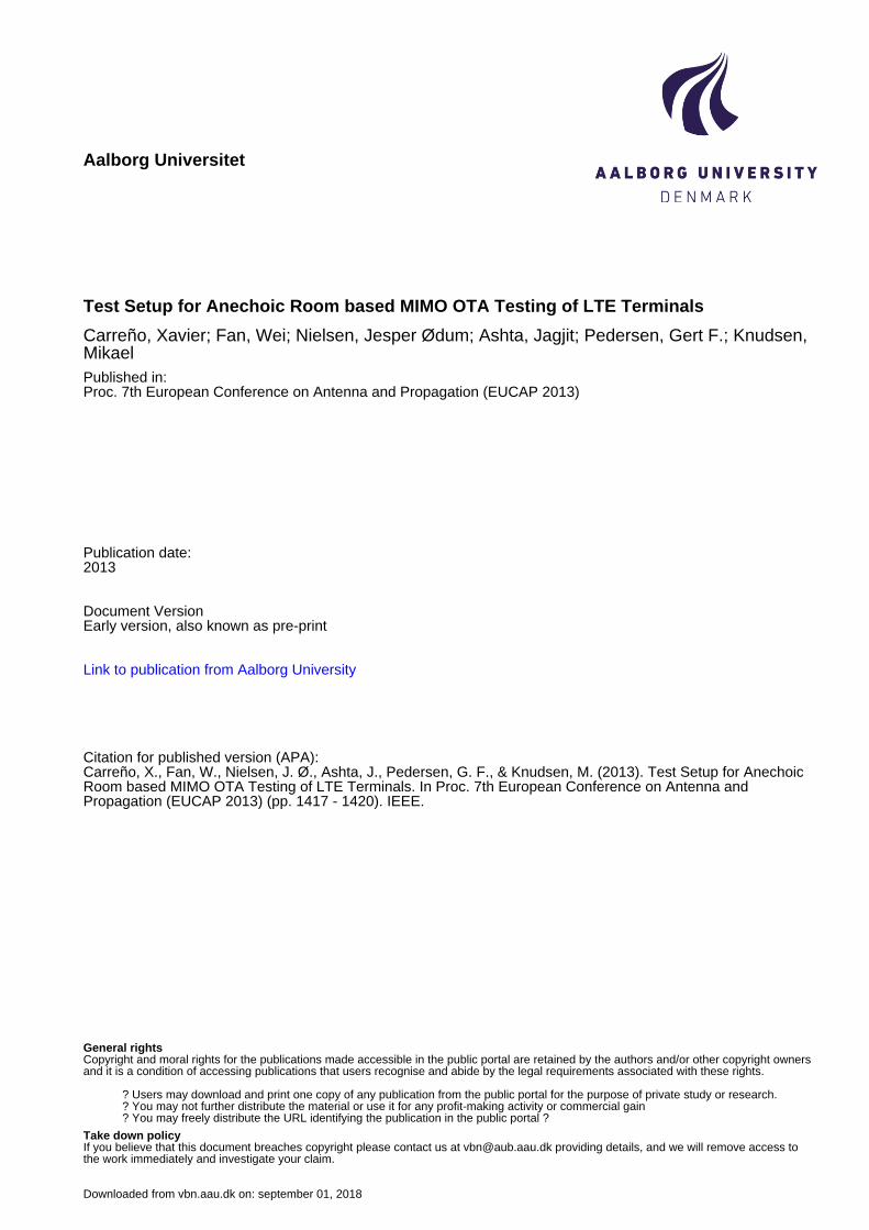
Figure 1 shows a simplified version of the multi-probe setupmounted at AAU for testing a device under test (DUT) whichis placed on a pedestal in an anechoic chamber surrounded by16 probes mounted on a 4 meters diameter ring. The probesare designed by AAU [7] and currently not all antennas can beconnected simultaneously with both polarizations due to thelimited number of fading channels in the channel emulators.The number of probes makes the setup suitable to test any
of the currently available LTE phones and most of the LTEtablets at the standardized LTE bands [5], [6].
Fig. 1: Basic scheme of multi-probe test technique used fortesting DUT with a BS emulator
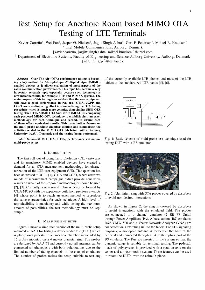
Fig. 2: Aluminium ring with OTA probes covered by absorbersto avoid non-desired interactions
As shown in Figure 2, the ring is covered by absorbersto avoid interactions with the emulated field. The probesare connected to a channel emulator (2 EB F8 Units)through Power Amplifiers (PA). A base station (BS) emulator,R&S CMW 500 and a Vector Network Analyzer (VNA) areconnected via a switching unit to the faders. For LTE signalingpurposes, a monopole antenna is located at the base of thepedestal and connected through a PA to the uplink port of theBS emulator. The PAs are inserted in the system so that thedynamic range is suitable for terminal testing. The pedestal,made of polystyrene, is provided with a rotation axis on thecenter and a linear motion system. These features can be usedto rotate the DUTs over the azimuth plane.
2
A software framework has been developed around each ofthe elements on the setup to automate all the functionalitiesfrom the system. This setup is intended for several purposesbut only LTE terminal testing is addressed on this document.
The system requires calibration [10], more details about thecalibration procedure and its consequences will be shown inthe full paper
III. MEASUREMENT CAMPAIGN DESCRIPTION
This document addresses two test campaigns being per-formed at AAU which are related on topic but differentiatedon purpose. Those are the CTIA MOSG round robin campaign[4] and Live LTE terminal test campaign.
A. Inter-Lab Inter-Technique OTA Performance ComparisonTesting for MIMO Devices
Its main goal is to establish a fair comparison between OTAtechniques, while tracking the ability of each methodology toreproduce the key characteristics of each channel profile [4].Using Absolute Throughput as the figure of merit (FoM) [8],the testing uses a fixed Modulation and Coding Scheme (MCS)and sweeps over Signal-to-Noise Ratio (SNR) calculated atthe receiver (RX) antenna ports and, optionally, over differentazimuth orientations. In order to control the effect of theantennas, the CTIA reference antennas are used while keepingthe DUT inside a metal box to diminish its interaction withthe environment [9].
B. Live LTE terminal test campaign
The goal is to be able to find a fair way to rank differentLTE devices, based on their ability to perform under differentconditions. This effort will include realistic channel modelsand also standardized profiles. Overall, it is intended to isolateand quantify the effect of the following characteristics:
• Channel profile• DUT orientation and position with respect to the channel• DUT antennas. CTIA reference antennas will be used.Throughput will also be used as FoM, although in its format
of link adaptation curves (LA) using 10 of the 28 availableMCS. For time variant channels, the number of blocks neededto get a converged BLER depends on the Doppler associatedchannel and also on the modulation scheme used. Note thattesting time also increases with the number of blocks used. Inthe end a variant number of block depending on the MCS willbe used. Other settings not specified here are set as in [4].
IV. RESULTS
Some examples to be shown in the full paper are presentedhere.
As a first approach, from all 16 dual polarized probes onthe ring only 2 probes are active on the vertical polarization.Those are located 45 degrees apart in azimuth, where eachis transmitting one of the downlink (DL) streams faded witha Rayleigh sequence and an associated Doppler of 70 Hz.The DUT will be facing one of the probes. Although thisconfiguration may not be realistic at all, its low complexity
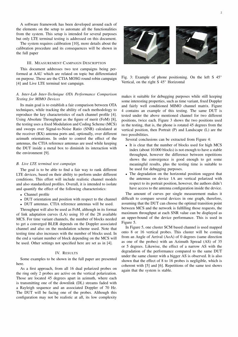
Fig. 3: Example of phone positioning. On the left S 45◦
Vertical, on the right S 45◦ Horizontal
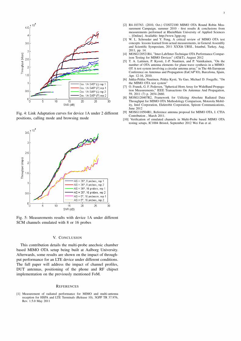
makes it suitable for debugging purposes while still keepingsome interesting properties, such as time variant, fixed Dopplerand fairly well conditioned MIMO channel matrix. Figure4 contains an example of this testing. The same DUT istested under the above mentioned channel for two differentpositions, twice each. Figure 3 shows the two positions usedin the testing, that is, the phone is rotated 45 degrees from thevertical position, then Portrait (P) and Landscape (L) are thetwo possibilities.
Several conclusions can be extracted from Figure 4:• It is clear that the number of blocks used for high MCS
index (about 10.000 blocks) is not enough to have a stablethroughput, however the difference between repetitionsshows the convergence is good enough to get somemeaningful results, plus the testing time is suitable tobe used for debugging purposes.
• The degradation on the horizontal position suggest thatthe antennas on device 1A are vertical polarized withrespect to its portrait position, however, the authors didn’thave access to the antenna configuration inside the device.
The amount of curves per single measurement makes itdifficult to compare several devices in one graph, therefore,assuming that the DUT can choose the optimal transition pointbetween MCS and the network is fulfilling those requests, themaximum throughput at each SNR value can be displayed asan upper-bound of the device performance. This is used inFigure 5.
In Figure 5, one cluster SCM based channel is used mappedonto 8 or 16 vertical probes. This cluster will be comingfrom an Angle of Arrival (AoA) of 0 degrees (same directionas one of the probes) with an Azimuth Spread (AS) of 35or 5 degrees. Likewise, the effect of a narrow AS with thedegradation of the performance compared to the same DUTunder the same cluster with a bigger AS is observed. It is alsoshown that the effect of 8 to 16 probes is negligible, which iscoherent with [5] and [6]. Repetitions of the same test showsagain that the system is stable.
3
Fig. 4: Link Adaptation curves for device 1A under 2 differentpositions, calling mode and browsing mode
Fig. 5: Measurements results with device 1A under differentSCM channels emulated with 8 or 16 probes
V. CONCLUSION
This contribution details the multi-probe anechoic chamberbased MIMO OTA setup being built at Aalborg University.Afterwards, some results are shown on the impact of through-put performance for an LTE device under different conditions.The full paper will address the impact of channel profiles,DUT antennas, positioning of the phone and RF chipsetimplementation on the previously mentioned FoM.
REFERENCES
[1] Measurement of radiated performance for MIMO and multi-antennareception for HSPA and LTE Terminals (Release 10), 3GPP TR 37.976,Rev. 1.5.0 May 2011
[2] R4-103763. (2010, Oct.) COST2100 MIMO OTA Round Robin Mea-surement Campaign, summer 2010 - first results & conclusions frommeasurements performed at RheinMain University of Applied Sciences-. [Online]. Available: http://www.3gpp.org
[3] W. L. Schroeder and Y. Feng, A critical review of MIMO OTA testconcepts lessons learned from actual measurements, in General Assemblyand Scientific Symposium, 2011 XXXth URSI., Istanbul, Turkey, Aug.2011, pp. 14.
[4] MOSG120521R4, ”Inter-Lab/Inter-Technique OTA Performance Compar-ison Testing for MIMO Devices” (AT&T), August 2012
[5] T. A. Laitinen, P. Kyosti, J.-P. Nuutinen, and P. Vainikainen, ”On thenumber of OTA antenna elements for plane-wave synthesis in a MIMO-OT A test system involving a circular antenna array,” in The 4th EuropeanConference on Antennas and Propagation (EuCAP’lO), Barcelona, Spain,Apr. 12-16, 2010.
[6] Jukka-Pekka Nuutinen, Pekka Kysti, Yu Gao, Michael D. Foegelle, ”Onthe MIMO OTA test system”
[7] O. Franek, G. F. Pedersen, ”Spherical Horn Array for WideBand Propaga-tion Measurements,” IEEE Transactions On Antennas And Propagation,59, 2011 (7) p. 2654-2660.
[8] MOSG120407R2, Framework for Utilizing Absolute Radiated DataThroughput for MIMO OTA Methodology Comparison, Motorola Mobil-ity, Intel Corporation, Elektrobit Corporation, Spirent Communications,June 2012
[9] MOSG110504R1, Reference antenna proposal for MIMO OTA, I. CTIAContribution , March 2011.
[10] Verification of emulated channels in Multi-Probe based MIMO OTAtesting setups, IC1004 Bristol, September 2012 Wei Fan et al.