대정a&g | 대정에이앤지
TRANSCRIPT
���������
1MRK 506 067-BEN
��� �������� ����� ������� ������
Page 1
Issued: August 2001Changed since: November 2000Data subject to change without notice
� ���� � • Open terminal with extensive configuration possibilities and expandable hardware design to meet specific user requirements
• Full scheme phase-to-phase and phase-to-earth distance protection with three to five zones
• Separate phase selector
• Wide range of phase and residual overcur-rent protection functions
• Additional protection function library avail-able
• Extensive disturbance report with:
- 10 most recent disturbances recorded
- 40 seconds disturbance recorder
• Wide range of control functionality avail-able
• 18 LEDs for extended indication capabili-ties
• Versatile local human-machine interface (HMI)
• Simultaneous dual protocol serial commu-nication facilities
• Extensive self-supervision with internal event recorder
• Time synchronization with 1 ms resolution
• Four independent groups of complete set-ting parameters
• Powerful software ‘tool-box’ for monitoring, evaluation and user configuration
����������� The main purpose of the REL 521 terminal is the protection, control and monitoring of overhead lines and cables in solidly grounded networks. It is suitable for the protection of long heavily loaded lines and multi-circuit
lines, and where the requirement for tripping is one-, two-, and/or three-pole. The terminal may also be used to provide backup protec-tion for power transformers, busbars, etc.
� ���� Type tested software and hardware that com-ply with international standards and ABB´s internal design rules together with extensive self monitoring functionality, ensure high reliability of the complete terminal.
The terminal’s closed and partly welded steel case makes it possible to fulfill the stringent EMC requirements.
All serial data communication is via optical connections to ensure immunity against dis-turbances.
An extensive library of protection, control and monitoring functions is available. This library of functions, together with the flexible hardware design, allows this terminal to be configured to each user´s own specific requirements. This wide application flexibil-ity makes this product an excellent choice for both new installations and the refurbishment of existing installations.

��� �������� ����� ������� ������ ���������1MRK 506 067-BEN
Page 2
� ��������������������
The terminal block diagram shows only included basic functions described in this document.
Optional functions which can be included are also described in the ordering chapter.
xx00000589.vsd
��
· 3 zones ph-ph and ph-E distance protection with additionalphase selection logic; plus
- scheme communication logic- current reversal and WEI logic- local acceleration logic
��
· 2-step non-directional residual overcurrent protectionStep 1: instantaneousStep 2: instantaneous or definite time-delayed
����
· Dead line detection
��
· 3-pole tripping logic
REL 521
Comm. toremote end
· 2-step non-directional phase overcurrent protectionStep 1: instantaneousStep 2: instantaneous or definite time-delayed
��
��� �������� ����� ������� ������ ���������1MRK 506 067-BEN
Page 3
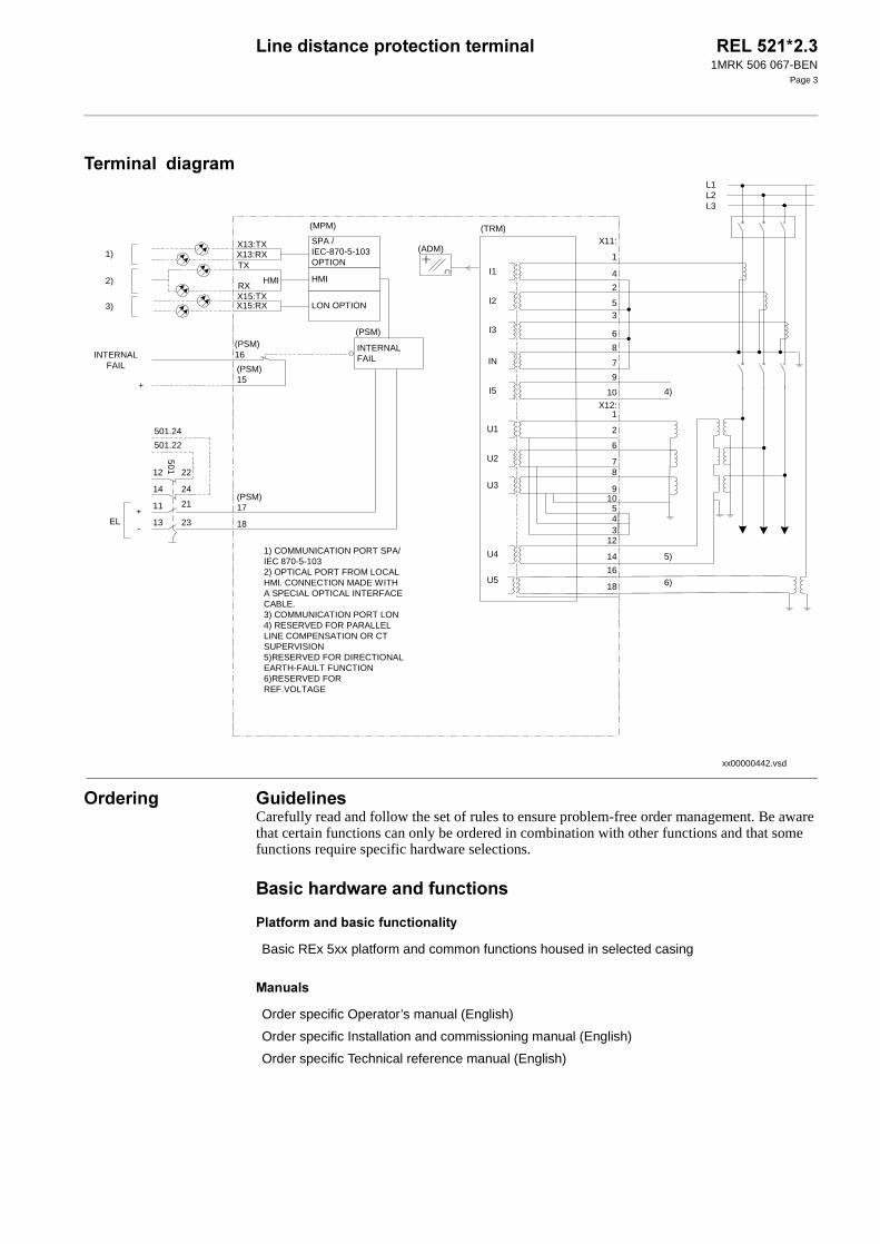
� ���������������
�� ���� !��� ��� �Carefully read and follow the set of rules to ensure problem-free order management. Be aware that certain functions can only be ordered in combination with other functions and that some functions require specific hardware selections.
"�����#���$�� �����%��������
&���%��������������%�����������'
(������
xx00000442.vsd
X13:RXX13:TX
TX
HMIRXX15:TXX15:RX
HMI
LON OPTION
SPA /IEC-870-5-103OPTION
(MPM)
+
-
(PSM)17
18
1)
2)
3)
EL
L2
1
L1
L3
X11:
4
2
53
6
8
7
9
10
1
2
6
78
910
543
12
14
16
18
X12:
5)
6)
4)
∩
(ADM)
INTERNALFAIL
(PSM)
INTERNALFAIL
(PSM)16
(PSM)15
+
12 22
14 24
11 21
13 23
501
501.24
501.22
I1
I2
I3
IN
I5
U1
U2
U3
U4
U5
(TRM)
1) COMMUNICATION PORT SPA/IEC 870-5-1032) OPTICAL PORT FROM LOCALHMI. CONNECTION MADE WITHA SPECIAL OPTICAL INTERFACECABLE.3) COMMUNICATION PORT LON4) RESERVED FOR PARALLELLINE COMPENSATION OR CTSUPERVISION5)RESERVED FOR DIRECTIONALEARTH-FAULT FUNCTION6)RESERVED FORREF.VOLTAGE
Basic REx 5xx platform and common functions housed in selected casing
Order specific Operator’s manual (English)
Order specific Installation and commissioning manual (English)
Order specific Technical reference manual (English)

��� �������� ����� ������� ������ ���������1MRK 506 067-BEN
Page 4
"����'�)* ����������� �
( ������������������ �
��� ���� ����
+��� ��
&�$ ���'�� ����� �,�����
�����
(���������
&��������� ��%�������
Binary I/O resided on power supply module
A/D module
Transformer module
3 zones phase-to-phase protection -.(�/�.(�/�.(0
3 zones phase-to-ground protection -.(�/�.(�/�.(0
Phase selection logic -&120
Scheme communication logic -.+ (0
Current reversal and weak end infeed logic -.+��0
Local acceleration logic -.+�+0
Instantaneous overcurrent protection -) +0
Phase element
Residual element
Time delayed overcurrent protection -� +0
Phase element
Residual element
Dead line detection -���0
Trip logic -��0
Three pole tripping
High speed binary output logic -12" 0
Event recorder
Analog AC monitor
REL 521 Quantity: 1MRK 002 494-AC
Default:
The terminal is delivered without loaded configuration.
������������ ��������������������������������������� ���������� ����������������������������������������� ���������������

��� �������� ����� ������� ������ ���������1MRK 506 067-BEN
Page 5
��������%��������
��� ���� ����
Option:
Customer specific configuration On request
��!�"��������#������������$��
Energizing quantities for binary inputs on power supply module
24/30 V 1MRK 000 179-EB
48/60 V 1MRK 000 179-AC
110/125 V 1MRK 000 179-BC
220/250 V 1MRK 000 179-CC
%���!�� ������#����$�������&'������()*����+�
��!�,������������� ������������������ ���������)�����������-,.���-�������,��� ����.�������������)����/����������������0��������� ������ �������1���2 ���������������������
OITP measuring system 1MRK 002 216-AA
��!�"��������#������������$���,�������$��������� ��� ��������#���� ������ ���/����������������������
Rated measuring input energizing quantities 1A, 110 V 1MRK 000 157-MA
1 A, 220 V 1MRK 000 157-VA
5 A, 110 V 1MRK 000 157-NA
5 A, 220 V 1MRK 000 157-WA
��!�"��������#������������$������������������������)�������������$��������� ��� ���������������������������������� ������
Rated measuring input energizing quan-tities for sensitive earth fault functions
1 A/0.1 A, 110 V 1MRK 000 157-XA
5 A/0.5 A, 110 V 1MRK 000 157-RA
Simplified impedance settings 1MRK 001 459-UA
Full scheme distance protection
Additional impedance zone 4 -.(30 1MRK 001 456-FA
Additional impedance zone 5 -.(�0 1MRK 001 456-GA
Power swing detection -&2�0 1MRK 001 456-LA
Power swing logic -&2�0 1MRK 001 456-SA
Pole slip protection -&2&0 1MRK 001 457-SA
Radial feeder protection -&�&0 1MRK 001 455-SA
Automatic switch onto fault logic -2 ��0 1MRK 001 456-RA

��� �������� ����� ������� ������ ���������1MRK 506 067-BEN
Page 6
+��� ��
4�����
&�$ ���'�� ����� �,�����
Two step time delayed phase overcurrent protection -� +�0 1MRK 001 459-LA
Two step time delayed directional phase overcurrent protec-tion -� +0
1MRK 001 457-CA
Thermal phase overload protection -�1 �0 1MRK 001 457-DA
Stub protection -2�5"0 1MRK 001 457-TA
Breaker failure protection -"�&0 1MRK 001 458-AA
��!�3� ������������ ����$��� ������������������4����������$��������������#�������� ����$��� ��������������������#����������������������#/��$�����������.
"���������� ����������������� �������$���������0�������������������������� ����$��� �������������������� ����������#�������0���3� ������������ ����$��� ���������������������������
Four step residual overcurrent protection -��30 1MRK 001 459-HA
Definite and inverse time delayed residual overcurrent pro-tection -���0
��!�,�"���������� ����������������� �������$��)�������0�������������������������� ����$��� ������������������������ ���/���#�������������������������#������������
Nondirectional element 1MRK 001 456-YA
Directional element 1MRK 001 459-ZA
Scheme communication logic -��+0 1MRK 001 455-UA
Current reversal and weak end infeed logic for residual over-current protection -��+�0
1MRK 001 455-VA
��!�.���������$������������ �������������������������������������������� ������ �������1���2 ���������������������
Sensitive directional residual overcurrent protection -6���0 1MRK 001 457-PA
Sensitive directional residual power protection -6���0 1MRK 001 459-TA
Time delayed phase undervoltage protection -�540 1MRK 001 457-RA
Time delayed overvoltage protection -� 40
Phase element 1MRK 001 457-GA
Residual element 1MRK 001 459-FA
Broken conductor check -"�+0 1MRK 001 457-UA
Loss of voltage check -� 40 1MRK 001 457-VA
Overload supervision - 4��0 1MRK 001 457-FA
��� �������� ����� ������� ������ ���������1MRK 506 067-BEN
Page 7
2 ������'��'�� ����� �,�����
+������
�����
(���������
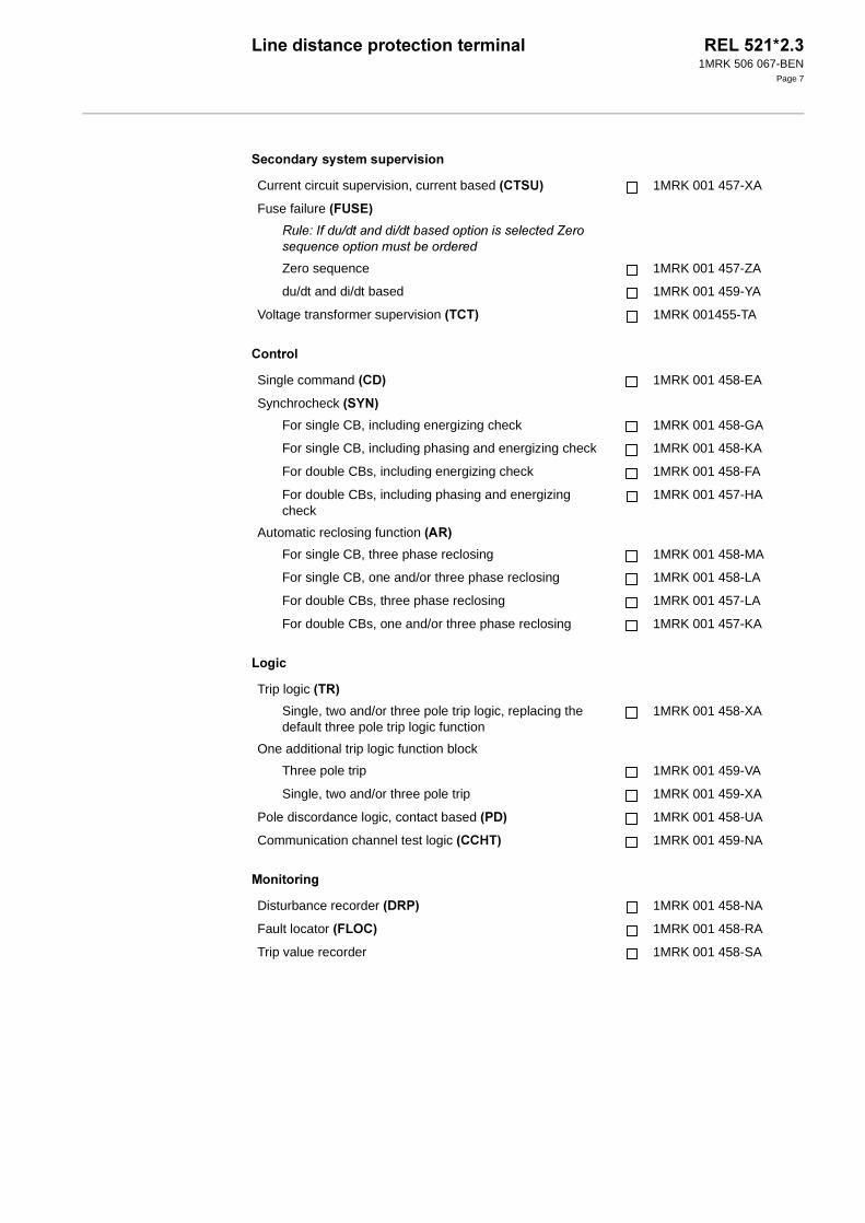
Current circuit supervision, current based -+�250 1MRK 001 457-XA
Fuse failure -�52�0
��!�,�� 5��������5���������������������������6������2 ����������� �������������
Zero sequence 1MRK 001 457-ZA
du/dt and di/dt based 1MRK 001 459-YA
Voltage transformer supervision -�+�0 1MRK 001455-TA
Single command -+�0 1MRK 001 458-EA
Synchrocheck -2780
For single CB, including energizing check 1MRK 001 458-GA
For single CB, including phasing and energizing check 1MRK 001 458-KA
For double CBs, including energizing check 1MRK 001 458-FA
For double CBs, including phasing and energizing check
1MRK 001 457-HA
Automatic reclosing function -��0
For single CB, three phase reclosing 1MRK 001 458-MA
For single CB, one and/or three phase reclosing 1MRK 001 458-LA
For double CBs, three phase reclosing 1MRK 001 457-LA
For double CBs, one and/or three phase reclosing 1MRK 001 457-KA
Trip logic -��0
Single, two and/or three pole trip logic, replacing the default three pole trip logic function
1MRK 001 458-XA
One additional trip logic function block
Three pole trip 1MRK 001 459-VA
Single, two and/or three pole trip 1MRK 001 459-XA
Pole discordance logic, contact based -&�0 1MRK 001 458-UA
Communication channel test logic -++1�0 1MRK 001 459-NA
Disturbance recorder -��&0 1MRK 001 458-NA
Fault locator -�� +0 1MRK 001 458-RA
Trip value recorder 1MRK 001 458-SA
��� �������� ����� ������� ������ ���������1MRK 506 067-BEN
Page 8
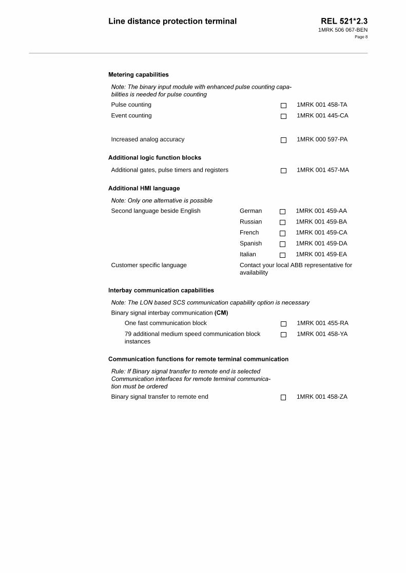
( � ��������������� �
�����������������%��������������
�����������1()��������
)�� ���'������������������������� �
+�������������%���������%���� ��� �� ��������������������
%���!�.�������#��� ����� ���0������������ ������ ��������)���������������������� ������ ���
Pulse counting 1MRK 001 458-TA
Event counting 1MRK 001 445-CA
Increased analog accuracy 1MRK 000 597-PA
Additional gates, pulse timers and registers 1MRK 001 457-MA
%���!�-�#������������$�������������
Second language beside English German 1MRK 001 459-AA
Russian 1MRK 001 459-BA
French 1MRK 001 459-CA
Spanish 1MRK 001 459-DA
Italian 1MRK 001 459-EA
Customer specific language Contact your local ABB representative for availability
%���!�.���'-%�������"�"����� ����������������#�����������������#
Binary signal interbay communication -+(0
One fast communication block 1MRK 001 455-RA
79 additional medium speed communication block instances
1MRK 001 458-YA
��!�,�7���#������������������������������������������� �������������������������������������� ���)����� �������������
Binary signal transfer to remote end 1MRK 001 458-ZA
��� �������� ����� ������� ������ ���������1MRK 506 067-BEN
Page 9
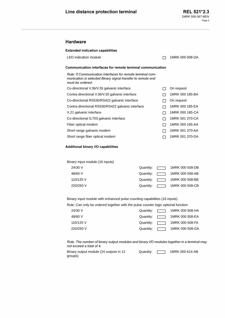
1���$��
�9� �� ����������������������� �
+���������������� �%�� ��%���� ��� �� ��������������������
����������������'�)* ����������� �
LED indication module 1MRK 000 008-DA
��!�,����� �������������������������������������)� �������������������7���#���������������������������� ��������������
Co-directional V.36/V.35 galvanic interface
Contra-directional V.36/V.35 galvanic interface
On request
1MRK 000 185-BA
Co-directional RS530/RS422 galvanic interface On request
Contra-directional RS530/RS422 galvanic interface 1MRK 000 185-EA
X.21 galvanic interface 1MRK 000 185-CA
Co-directional G.703 galvanic interface 1MRK 001 370-CA
Fiber optical modem 1MRK 000 195-AA
Short range galvanic modem 1MRK 001 370-AA
Short range fiber optical modem 1MRK 001 370-DA
Binary input module (16 inputs)
24/30 V Quantity: 1MRK 000 508-DB
48/60 V Quantity: 1MRK 000 508-AB
110/125 V Quantity: 1MRK 000 508-BB
220/250 V Quantity: 1MRK 000 508-CB
Binary input module with enhanced pulse counting capabilities (16 inputs)
Rule: Can only be ordered together with the pulse counter logic optional function
24/30 V Quantity: 1MRK 000 508-HA
48/60 V Quantity: 1MRK 000 508-EA
110/125 V Quantity: 1MRK 000 508-FA
220/250 V Quantity: 1MRK 000 508-GA
��!�.��� �����������#�� �� ����� �����������#�,5-���� ���������������������������#�����������������������
Binary output module (24 outputs in 12 groups)
Quantity: 1MRK 000 614-AB

��� �������� ����� ������� ������ ���������1MRK 506 067-BEN
Page 10
+�� ���: Compare the sum of the ordered quantities of I/O modules with the table below and select the case size which has the larger or equal number of slots available.
���� ��;�(�9�����#���$�� ����%�����������%���)* ������ �
2+2�����2(2������������������������� �
��!�.��� �����������#�,5-���� �����������#�� �� ����� ���������������������������#�����������������������
Binary I/O module (8 inputs, 10 outputs, 2 high-speed outputs)
24/30 V Quantity: 1MRK 000 173-GB
48/60 V Quantity: 1MRK 000 173-AC
110/125 V Quantity: 1MRK 000 173-BC
220/250 V Quantity: 1MRK 000 173-CC
Milliampere input module Quantity: 1MRK 000 284-AA
Maximum number of modules
Case size
3/4 x 19”
1MRK 000 151-GC
1/2 x 19”
1MRK 000 151-FC
Binary input/output (IOM) and output (BOM) modules
4 3
Binary input modules (BIM)
8 3
mA input modules (MIM)
1 1
Communication inter-face for remote termi-nal communication
1 1
������������ <
SMS communication, only one alternative can be selected
SPA/IEC 60870-5-103 interface Plastic fibers 1MRK 000 168-FA
Glass fibers 1MRK 000 168-DA
SCS communication, only one alternative can be selected
LON interface Plastic fibers 1MRK 000 168-EA
Glass fibers 1MRK 000 168-DA
��� �������� ����� ������� ������ ���������1MRK 506 067-BEN
Page 11
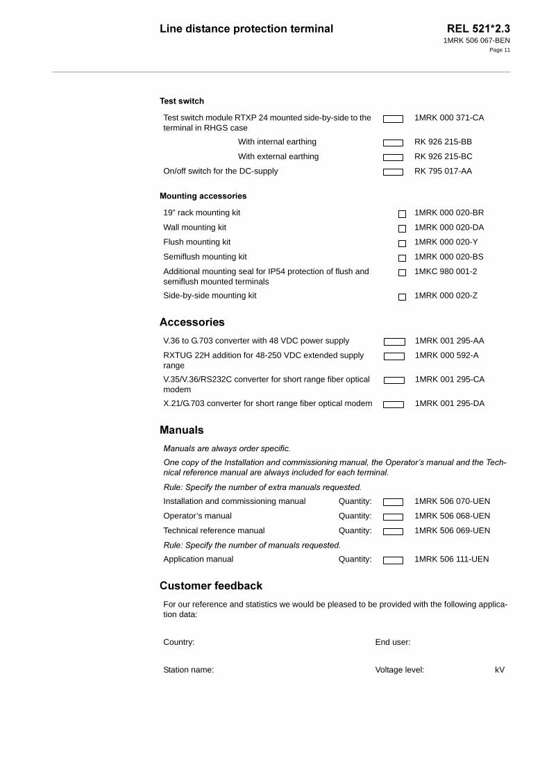
� ����$���#
(����������� ����� �
��� ����� �
(������
+����� ��% �����
Test switch module RTXP 24 mounted side-by-side to the terminal in RHGS case
1MRK 000 371-CA
With internal earthing RK 926 215-BB
With external earthing RK 926 215-BC
On/off switch for the DC-supply RK 795 017-AA
19” rack mounting kit 1MRK 000 020-BR
Wall mounting kit 1MRK 000 020-DA
Flush mounting kit 1MRK 000 020-Y
Semiflush mounting kit 1MRK 000 020-BS
Additional mounting seal for IP54 protection of flush and semiflush mounted terminals
1MKC 980 001-2
Side-by-side mounting kit 1MRK 000 020-Z
V.36 to G.703 converter with 48 VDC power supply 1MRK 001 295-AA
RXTUG 22H addition for 48-250 VDC extended supply range
1MRK 000 592-A
V.35/V.36/RS232C converter for short range fiber optical modem
1MRK 001 295-CA
X.21/G.703 converter for short range fiber optical modem 1MRK 001 295-DA
8� ����������0�#����������������
-�����#�������,��������������������������� ��/�����-�������9���� ����������.���)��������������� ���������0�#����� ��������������������
��!�"����#����� ��������������� ������2 ������
Installation and commissioning manual Quantity: 1MRK 506 070-UEN
Operator’s manual Quantity: 1MRK 506 068-UEN
Technical reference manual Quantity: 1MRK 506 069-UEN
��!�"����#����� ��������� ������2 ������
Application manual Quantity: 1MRK 506 111-UEN
For our reference and statistics we would be pleased to be provided with the following applica-tion data:
Country: End user:
Station name: Voltage level: kV

��� �������� ����� ������� ������ ���������1MRK 506 067-BEN
Page 12
� ��� ������� ���
(���%����� �
� �#�������, �,� $�����#��
Platform 1MRK 580 063-BEN
Measuring capabilities 1MRK 580 083-BEN
Binary I/O capabilities 1MRK 580 081-BEN
Current measurement capabilities 1MRK 580 082-BEN
Remote terminal communication 1MRK 580 093-BEN
Extended indication capabilities 1MRK 580 080-BEN
Accessories 1MRK 514 009-BEN
CAP 540*1.1 1MRK 511 104-BEN
�""������������� �#�����'�&���������"
Instrumentation & Control
Substation Automation
SE-721 59 Västerås
Sweden
Tel: +46 (0) 21 34 20 00
Fax: +46 (0) 21 14 69 18