aap01 spacemaker - arrow sheds 15-0630804.pdf · english instructions pages 2 - 7 instructions en...
TRANSCRIPT

English Instructions Pages 2 - 7Instructions en français Pages 8 - 14Instrucciones en español Páginas 15 - 20
Spacemaker
AAP01
15-0630804 08/04
FDN10789FOUNDATION UNIT /
ÉLÉMENT DE FONDATION /UNIDAD DE CIMENTACIÓN

SpacemakerASSEMBLY INSTRUCTIONSFor buildings with base dimensions of 10' x 7'(3.04 m x 2.13 m), 10' x 8' (3.04 m x 2.43 m),and 10' x 9' (3.04 m x 2.74 m). This FoundationUnit is designed to provide your garden buildingwith a stable and durable foundation. It canaccommodate your choice of concrete or ply-wood flooring.
·ity and telephone may also require notification before digging commences.
Read all instructions for the Foundation Unit, optional Anchor Kit and GardenBuilding for an understanding of overall assembly requirements. Familiarizeyourself with each carton's contents and ensure that all parts are present.
Important... Requests for replacement parts or questions regarding your Foun-dation Unit should be referred directly to the factory. Do not contact yourDealer; they are not equipped to service your request. Contact the CustomerService Department, 3069 Wolfedale Road, Mississauga, Ontario, Canada L5C1V9, Telephone: 1-800-851-1085.
Ensure the construction site is level.
For your own safety:- Wear suitable footwear, work gloves, long sleeves and safety glasses.- Do not use electrical equipment in a wet environment.- Do not stand on unsupported Foundation Unit framework.- Beware of sharp edges. Use gloves and handle with care.
Before starting construction, check build-ing code requirements with your localauthority. Utilities such as gas, electric-
GETTING READY
·
AAP02
FOUNDATION UNITFDN10789
·
2
·
CARTON CONTENTS2 Frame pcs #FL05 (174cm - 68 1/2")14 Frame pcs #FL04 (146.4cm - 57 5/8")6 Frame pcs #FL02 (65.4cm - 25 3/4")3 Frame pcs #FL03 (48.9cm - 19 1/4")10 Base rail brackets 21F4 Corner brackets #BR2 (64.8cm - 25 1/2")102 10mm (3/8") long bolts and nuts18 10mm (3/8") self-tapping screws
Fig. #1

AAP03TOOLS REQUIREDa. Spade or shovelb. Large spirit levelc. 3-4m(12-16 ft.) tape measured. Phillips #2 screwdriver (Magnetized head recommended)e. Small adjustable wrenchf. Electric drill (and extension cord)g. Socket wrench with 5/16" Hex. socketh. 7/64" drill bit (for steel)
OTHER MATERIALS REQUIRED FOR CONCRETE FLOORING1. Coarse sand2. Crushed stone3. Concrete mix4. Plastic vapour barrier5. Steel reinforcing mesh6. A number of wood pointed stakes 50 x 5 x 5 cm (20" x 2" x 2")
OTHER MATERIALS REQUIRED FOR PLYWOOD FLOORING1. Exterior quality plywood sheets with minimum thickness of 16mm (5/8").2. Masonry blocks for levelling and supporting foundation frame on uneven grade.3. Countersunk, self-tapping screws for fastening plywood to steel foundation frame.
ASSEMBLING THE FOUNDATION UNIT
3
Check your Garden Building instruction booklet for the base rail dimensions of yourparticular building.
Mark out selected site for foundation and remove all surface vegetation. Compactthe ground underneath when plywood flooring is planned. Excavation area of thebase for concrete flooring is slightly smaller than the Foundation Unit's outer frame.Ensure site is level. Choose an assembly area for the foundation frame that isclose to the construction site.
Using the illustration corresponding to the size of your building, place thefoundation sections into position, so a rectangular frame is formed. (See figure #2.)Using bolts and nuts, attach all frame sections together through the fixing holesfound on the upper and lower surfaces of each foundation section. (See Figure #13for exact lengths.)
1.
2.
3.
4.
FL04
FL04
FL04
FL04
Fig. #2
FL04FL05
Assemble the four inner FL04sub-frame assemblies using theillustration corresponding to thesize of your building.
FL04
FL05
4
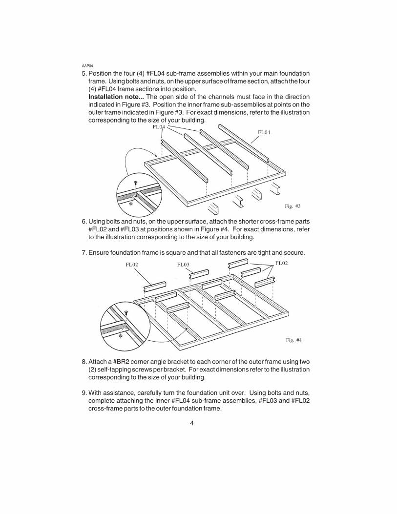
Position the four (4) #FL04 sub-frame assemblies within your main foundationframe. Using bolts and nuts, on the upper surface of frame section, attach the four(4) #FL04 frame sections into position.Installation note... The open side of the channels must face in the directionindicated in Figure #3. Position the inner frame sub-assemblies at points on theouter frame indicated in Figure #3. For exact dimensions, refer to the illustrationcorresponding to the size of your building.
Using bolts and nuts, on the upper surface, attach the shorter cross-frame parts#FL02 and #FL03 at positions shown in Figure #4. For exact dimensions, referto the illustration corresponding to the size of your building.
Ensure foundation frame is square and that all fasteners are tight and secure.
Attach a #BR2 corner angle bracket to each corner of the outer frame using two(2) self-tapping screws per bracket. For exact dimensions refer to the illustrationcorresponding to the size of your building.
With assistance, carefully turn the foundation unit over. Using bolts and nuts,complete attaching the inner #FL04 sub-frame assemblies, #FL03 and #FL02cross-frame parts to the outer foundation frame.
5.
6.
7.
8.
9.
FL04
FL02 FL03
Fig. #3
Fig. #4
AAP04
FL02
FL04

5
Fig. #6
Fig. #5
Once completed, carefully turn foundation frame over to its original position.
Excavate site to a depth of 20cm (8"). NOTE... Make excavation area slightlysmaller than the Foundation Unit's outer frame. (See Figure #6.)
Cover bottom of excavation with a layer of crushed stone 10cm (4") deep andcompact material down. Cover the crushed stone with a 5cm (2") layer of coarsesand and compact down. (See Figure #7.)
eter of the frame. (These will be removed after the concrete has hardened.) Nowremove the Foundation Unit from the area leaving the wooden stakes in place.
Pour the first layer of concrete 5cm (2") deep. Place the steel reinforcing meshover the poured concrete. Replace the Foundation Unit back into position insidethe wooden stakes. Make a final check for level and positioning.
10.
For concrete flooring, see instruction 11 to 19.
For plywood flooring, see instruction 20 to 24.
FOR CONCRETE FLOORING
11.
12.
13.
14.
15.
16.
Place a sheet of plastic vapour bar-rier over the compacted sand.
With assistance, place assembledFoundation Unit over the excavationarea. Note... Outer frame of theFoundation Unit rests on grade justbeyond the sides of the excavation.(See Figure #8.)
Ensure the foundation frame issquare, level and positioned in itsfinal location. Drive wooden stakesinto the ground around the perim- Fig. #7
CRUSHED STONECOARSE SAND
VAPOUR BARRIER
BR2BR2

CONCRETE
surface can be obtained with light troweling. NOTE... Allowtime for concrete to harden thoroughly before proceeding to the next stage.
Assemble Garden Building base rails as described in your Garden Buildinginstruction booklet. Position base rail assembly onto (hardened) concrete base.
Ensure your building base rail assembly is square and placed in its final fixingposition. All your buildings Base Rails, Front Base Rails and Entry Ramp arerequired to be attached to the foundation using anchor screws, each screw beingplaced through the existing 6.3mm (1/4") fixing holes provided in thesecomponents. Use your chosen anchors or the optional Spacemaker Founda-tion Anchor Kit. The #21F Brackets provided in your kit are not required to beused with a solid concrete base. However, they may be used for additionalanchoring if desired.
Determine the quantity of plywood sheets to be purchased for your building fromthe cutting diagram corresponding tothe size of your building.
Foundation Unit on the prepared site.Ensure the Foundation Unit is square, level and located in its final position.Masonry blocks should be placed under the framework in areas of uneven gradewith particular attention to center connection points. NOTE... The centersections of the Foundation Unit will not support extra weight without blocking.Do not stand on framework during construction. (See Figure #9.)
Assemble Garden Building base rails as descibed in your Garden Buildinginstruction booklet. Position the base rail on top of the Foundation Unit frameand ensure that it is square and level. Position a #21F Base Rail Bracket ateach of the rear and side junctions of the inner frame and outer frame, positionthe flange of the #21F bracket over the base rail of your building. (See Figure#10.) Using a single bolt and nut for each #21F bracket, attach the brackets tothe inner foundation frame sections. INSTALLATION NOTE... Do not use the#21F Brackets along the Front Base Rails as they may interfere with the slidingdoors of your building. Secure Front Base Rails and Entry Ramp to yourfoundation frame using bolts and nuts through the fixing holes provided infoundation frame, Front Base Rails and Entry Ramp. Drill a 7/64" pilot hole asrequired and use a self tapping screw to fasten the #21F Base Rail Bracket tothe Base Rail.
Continue to spread concrete evenlyover the Foundation Unit, prodding thor-oughly to eliminate air pockets withinthe mix. Skim the surface with a plankto attain an even surface. A smooth
REINFORCING MESH17.
18.
19.
20.
21. With assistance, place the assembled
22.
MASONRY BLOCK Fig. #9
6
Fig. #8
FOR PLYWOOD FLOORING

21F
23.
24.
Important note... We recommend any buildingfitted with a wooden floor is also secured to theground with "Ground Anchors", sometimes re-ferred to as "Hurricane Anchors". These GroundAnchors may be purchased from your localHardware Store.
Continued on page 21.
7
Cut plywood to fit inside the buildingbase rails. (See Figure #11.)NOTE... all joining edges of plywood must,where possible, meet at the center of aframe section. (See Figure #12.) Joiningplywood over a lengthwise void could resultin a weak and unsafe floor. Shape plywoodto fit around inner edge of Entry Ramp.Optionally, carefully bend the inside metaledge of the Entry Ramp upwards to suit thelevel of the plywood flooring, a groove hasbeen provided in the Entry Ramp to assistyou in this bending process.
Fasten plywood to the Foundation Unitframework using purchased drywall screws.For safety, ensure the screws are drivenflush to, or below, the plywood flooringsurface.
Fig. #10
Fig. #11
Fig. #12
BEND HERE
Note regarding your Building... If your model of building does not have thenecessary holes in the Front Base Rails and Entry Ramp to line up with thefoundation frame, it is necessary to drill a 1/4" (6.3mm) hole at each end of theEntry Ramp and a 1/4" (6.3mm) in each of the Front Base Rails so that the FrontBase Rails and Entry Ramp can be attached to the foundation frame.

21Fig. #13
7' (2.13 m) Side /2,13 m (7 pi) Côte /Lado de 2.13 m (7')
8' (2.44 m) Side /2,44 m (8 pi) Côte /Lado de 2.44 m (8')
9' (2.74 m) Side /2,74 m (9 pi) Côte /Lado de 2.74 m (9')
10' (3.05 m) Front/Rear /3,05 m (10 pi) Avant/Arrière /3.05 m (10') Adelante/Atrás
Nota Importante: Recomendamos quecualquier caseta provista con piso de maderatambién se fije al suelo con "Anclajes para elSuelo", a veces referidos como "Anclajes aprueba de Huracanes". Estos Anclajes paraSuelo pueden comprarse en cualquierferretería local.
Fig. #12

22
10' x 7' (10 pi x 7 pi / 3,04 m x 2,13 m)
Fig. #14
Fig. #15
ENTRANCEENTRÉEENTRADA

10' x 8' (10 pi x 8 pi / 3,04 m x 2,43 m)
Fig. #16
Fig. #17
23
ENTRANCEENTRÉEENTRADA

24
10' x 9' (10 pi x 9 pi / 3,04 m x 2,74 m)
Fig. #18
Fig. #19
ENTRANCEENTRÉEENTRADA