aas 10-467 lore: lunar origins and …psf.uwinnipeg.ca/publications/adv astron sci v138...685 •...
TRANSCRIPT

681
INTRODUCTION
The Moon, our nearest neighbor, has tremendous scientific significance as a repository of four billion years of solar system history, as well as providing a test-bed to validate technologies and methodologies to explore more distant asteroids and planets.
The lunar polar regolith is a potential fossil record of the Earth-Moon impact history. While the combination of vacuum and incident solar UV light will tend to dissociate most volatile spe-cies in solar-exposed regions, it is speculated that a fraction of the volatiles deposited by prior impacts, including H2O, may have migrated towards the lunar polar regions, and condensed in Sun-shaded areas, leaving a record of lunar impact history and possible volatile degassing.
Moreover, the feasibility of extended human presence on the Moon depends critically on in-situ resource utilization (ISRU) to mitigate the high interplanetary transportation costs. Key re-source requirements include water, oxygen, and a variety of building materials. Of the potential lunar resources, ilmenite is one of the most energetically favourable sources1 to process to obtain oxygen, while the iron and titanium materials can be used in steel production; ilmenite is also the lunar mineral most susceptible to solar wind implantation of hydrogen.
AAS 10-467
LORE: LUNAR ORIGINS AND RESOURCE EXPLORER
R. V. Kruzelecky, B. Wong, J. Zou, E. Haddad, W. Jamroz,*
E. Cloutis,†
K. Strong,‡
A. Ellery,**
Nadeem Ghafoor and Gita Ravindran††
The LORE Lunar Origins and Resource Explorer miniature payload is proposed for
JAXA‘s Selene 2 landed lunar mission. LORE is designed to provide, for the first
time, systematic exploration of the lunar surface and subsurface ice distribution,
implanted H, dust, mineralogy and resources, using UV/VIS/MIR spectroscopy.
Preliminary supporting laboratory investigations at the University of Winnipeg sug-
gest that the UV region can provide new geological information unobtainable by
other techniques, and in particular, abundances of ilmenite and related lunar oxides,
key potential in situ resources for oxygen and solar wind-implanted hydrogen. The
LORE stand-off measurement capabilities will be used to provide studies of lunar
exospheric diurnal processes with high temporal resolution.
The spectral differences between ilmenite and other lunar minerals in the ultravio-
let region will be exploited for mapping ilmenite distribution and abundances on
the lunar surface and subsurface. A miniature robotic drill with integral bore-hole
probe will facilitate subsurface pristine mapping of the lunar polar regolith stratig-
raphy and condensed volatile content to elucidate prior impact history and trapped
volatile content.
* MPB Communications Inc., 151 Hymus Blvd., Pointe Claire, Quebec, Canada.
E-mail: [email protected].
† University of Winnipeg, Canada. E-mail: [email protected].
‡ University of Toronto, Canada. E-mail: [email protected].
** Carleton University, Canada. E-mail: [email protected].
†† MDA Space Missions, 9445 Airport Road, Brampton, Ontario, Canada.
E-mail: [email protected].

682
The moon is currently the focus of several robotic exploration missions. In this respect, opti-cal spectrometers are playing a major role in providing compositional mapping of the moon. In particular, infrared spectroscopy probes the characteristic vibrational and rotational modes of chemical bonds in molecules to provide information about both the chemical composition and the bonding configuration of a sample. This provides high specificity for the identification of a wide range of unknown substances in vapor, liquid or solid form. IR reflectance spectroscopy provides direct information on the presence of H2O or OH, either as free H2O or bonded within hydrated minerals through the measurement of the fundamental H-O-H vibrational stretching modes near 3 μm, as well as overtone modes such as the O-H (hydroxyl) stretch near 1.4 μm and the combina-tion H-O-H bend/stretch mode near 1.9 μm2.
The Japanese-led JAXA Kaguya Selene-1 mission3, launched in 2007, targeted the global characterization of the lunar surface and detailed gravimetry from an orbiter platform. Kaguya consists of a Main Orbiter at 100km altitude and two small satellites (Relay Satellite and VRAD Satellite) in polar orbit. Kaguya is providing global data on element abundance, mineral assem-blage, surface topography, sub-surface structure, magnetic and gravity field, and precession. The aim is to better understand the origin and evolution of the Moon by these observations. The scien-tific data is also being used to explore the possibility of future utilization of the Moon.
Selene-1 is using a bulk-optic spectral profiler (SP) operating from 500 to 2600 nm at about 6-8 nm spectral resolution to provide mineralogical maps of the moon from an altitude of about 100 km with a spatial pixel size of 500 m. It also has a multi-spectral imager (MI) which collects data with a spatial resolution of ~2o metres in selected band passes.
Other relevant spectral instruments include the Moon Mineralogy Mapper (M3) spectrome-ter4 on India’s Chandrayaan-1, launched in 2008. The M3 instrument on Chandrayaan-1 is sensi-tive out to 3 microns (3000 nm), sufficient to provide some discrimination of different forms of hydroxyl. Differences in the appearance of the 3 micron region absorption band are attributable to changes in the form of O+H; liquid water, ice, and structural water all show differences in this wavelength region (see Figure 1).
Figure 1. Laboratory reflectance spectra of different forms of O+H, showing how the form of hydroxyl can be discriminated from the char-acteristics of the O-H stretching fun-damental band in the 3 micron re-gion. The clear region up to 3 mi-crons shows the limit of the M3 spec-trometer on Chandrayaan-14.
683
The M3 measurements have provided solid evidence for the presence of some form of water or hydroxyl that is concentrated in the polar regions of the Moon as evidenced by the detection of the 2.8-3.0 μm absorption band associated with H2O. For silicate bodies, such features are typi-cally attributed to OH- and/or H2O-bearing materials2. On the Moon, the feature is seen as a widely distributed absorption that appears strongest at colder high latitudes and at several fresh feldspathic craters. The general lack of correlation of this feature in sunlit M3 data with neutron spectrometer H abundance data suggests that the formation and retention of OH and H2O is an ongoing surficial process. The OH/H2O production processes may feed polar cold traps and make the lunar regolith a candidate source of volatiles for human exploration.
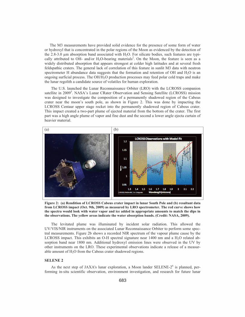
The U.S. launched the Lunar Reconnaissance Orbiter (LRO) with the LCROSS companion satellite in 20095. NASA’s Lunar CRater Observation and Sensing Satellite (LCROSS) mission was designed to investigate the composition of a permanently shadowed region of the Cabeus crater near the moon’s south pole, as shown in Figure 2. This was done by impacting the LCROSS Centaur upper stage rocket into the permanently shadowed region of Cabeus crater. This impact created a two-part plume of ejected material from the bottom of the crater. The first part was a high angle plume of vapor and fine dust and the second a lower angle ejecta curtain of heavier material.
(a) (b)
Figure 2: (a) Rendition of LCROSS Cabeus crater impact in lunar South Pole and (b) resultant data from LCROSS impact (Oct. 9th, 2009) as measured by LRO spectrometer. The red curve shows how the spectra would look with water vapor and ice added in appropriate amounts to match the dips in the observations. The yellow areas indicate the water absorption bands. (Credit: NASA, 2009).
The levitated plume was illuminated by incident solar radiation. This allowed the UV/VIS/NIR instruments on the associated Lunar Reconnaissance Orbiter to perform some spec-tral measurements. Figure 2b shows a recorded NIR spectrum of the vapour plume cause by the LCROSS impact. This exhibits an O-H spectral signature near 1400 nm and a H2O related ab-sorption band near 1800 nm. Additional hydroxyl emission lines were observed in the UV by other instruments on the LRO. These experimental observations indicate a release of a measur-able amount of H2O from the Cabeus crater shadowed regions.
SELENE 2
As the next step of JAXA's lunar exploration, a Moon lander SELENE-26 is planned, per-forming in-situ scientific observation, environment investigation, and research for future lunar

684
utilization including human activity. At the same time, it will demonstrate some key technologies for lunar and planetary exploration such as precise and safe landing, surface mobility and night survival technologies. Mission definition of SELENE-2 was completed in the spring of 2007 and a conceptual design of the spacecraft is now under study, advancing the project to phase A.
In the present design, SELENE-2 consists of a 1000 kg-class lander (Figure 3a), a 100 kg-class rover (Figure 3b) , and a communication relay orbiter. A twin lander configuration is also being studied as an option. Candidate landing sites are now under discussion. One of the candi-dates is quasi-eternal sunlit area in polar region in order to avoid long-term night. There, the lan-der would survive the lunar night using a relatively small fuel cell battery. However, there exist risks to landing on dark areas due to guidance errors of landing. On the other hand, landing on a lower latitude area is not sensitive to guidance error, but longer night survival will be required. From a scientific point of view, multiple landing site candidates exist. Trade-off of site selection is needed considering the required technologies and mission output.”
(a) Selene-2 Lander (b) Selene-2 Rover
Figure 3: Artists rendition of (a0 Selene-2 precision lander and (b) 100 kg-class lunar rover.
LORE
The LORE (Lunar Origins and Resource Explorer) science payload is designed to conduct surface and subsurface spectroscopic investigations and imaging for potential accommodation on the JAXA Selene-2 lander and/or rover7. LORE complements the key science and technology themes of the JAXA Selene-2 landed lunar mission and the Global Exploration Strategy, address-ing science issues (e.g., lunar surface geology and evolution), surface operation issues (e.g., na-ture of lunar dust and regolith, electrostatic dust levitation), and lunar usage issues (e.g., identifi-cation of key lunar in situ resources: hydrogen and ilmenite). In the context of a lander, and spe-cifically Selene-2, it is designed to serve as a crucial “calibration point” or “ground truth” for or-biters to provide a link to actual ground conditions.
LORE will provide UV/Vis/IR spectral data useful for many applications: in situ resource utilization, lunar geology, exploration, and lunar surface activities. Briefly, LORE is configured to acquire data from 300 to 3300 nm at a user-defined spectral resolution. This wavelength range allows the following science and exploration goals to be addressed:
• Map the surface/subsurface distribution of ice and other volatiles as verified by M3 on Chandrayaan-1 and LCROSS/LRO;

685
• In-situ study of the lunar dust; this knowledge will be critical for future manned missions and sustained lunar outposts; determine the lunar regolith photometric properties (useful for deriving physical properties of regolith/dust)8;
• Measure atmospheric dust loadings and electrostatic levitation (for understanding the im-pact of dust on surface operations);
• Map the distribution and abundance of ilmenite in target areas. Ilmenite is a key lunar re-source because of its association with solar wind implanted hydrogen and helium 3, its ease of processing for oxygen extraction, and its provision of iron and titanium for steel production9,10;
• Identify the maturity of targets (in conjunction with ilmenite abundances) to better con-strain possible hydrogen and helium abundances in terrains with high ilmenite/titanium abundances;
• Relate ilmenite abundances to other target properties (major silicate abundances and compositions) to better constrain models of lunar evolution;
• Determine the maturity of the lunar surface (important for assessing solar wind implanted elemental inventories and for age dating of surfaces)11;
• Determine the mafic silicate geology of a site (important for understanding the geological diversity and history of the Moon) 12.
The ability of LORE to map ilmenite abundances and maturity variations is a valuable capa-bility, not only for resource evaluation, but also for understanding the geology of the Moon. De-terminations of maturity are important for relative age dating of different terrains, providing a better chronology of lunar surface evolution, enabling us to better address issues such as the na-ture of the late heavy bombardment 13. Application of maturity determinations to other lunar fea-tures, such as pyroclastic deposits and crater rays, for example, would enable better determina-tions of the history of lunar volcanism and impact frequency14.
The LORE science encompasses the correlated study of three elements:
1. Lunar residual atmosphere/dust and its diurnal variations, 2. Lunar surface geology and ilmenite distribution15,3. Lunar subsurface stratigraphy, regolith grain size variation with depth, subsur-
face location of volatiles and ice from prior impacts, and mineralogy.
The mission will be achieved cost-effectively on a small, solar-powered rover (see Figure 4) or lander platform using a miniature suite of synergistic diagnostic instruments and additional fiber-optic sensors operating in collaboration with an extendable tethered mole drill. An integral bore-hole probe will provide systematic in-situ subsurface exploration of planetary stratigraphy, mineralogy and microbiology.
By using a reconfigurable foreoptic and beam distribution assembly, the LORE instrument can fulfill multiple goals. These include:
• Close-up and to-the-horizon imaging of the Selene-2 landing site, • Deep-sky imaging for dust studies, • In situ down-hole spectral measurements and imaging for subsurface investigations.

686
Figure 4: Rendition of preliminary LORE instrument/drill concept for a small rover.
A miniature robotic drill with integral bore-hole probe (see Figure 4) will facilitate subsurface pristine mapping of the lunar polar regolith stratigraphy and condensed volatile content to eluci-date prior impact history and trapped volatile content.
The LORE Science team includes international participation and expertise in all aspects re-quired for the LORE science and the associated data analysis, as summarized in Table 1.
Table 1: Summary of the preliminary LORE science team members.
Dr. Edward Cloutis U. of Winnipeg LORE Science Principal Investigator Dr. Makiko Ohtake JAXA Selene-1 and -2 camera/spectrometer PI: Dr. Kimberly Strong University of Toronto Instrument calibration and validation,
Lunar atmospherics. Dr. Alex Ellery Carleton Lunar robotics and operations Dr. Paul Lucey University of Hawaii Development of ilmenite and maturity al-
gorithms Dr. Mark Robinson Arizona State (LRO camera PI): development of ilmen-
ite algorithms Dr. Brad Jolliff Washington University (New Frontiers lunar sample return mis-
sion PI): geological mapping criteria Dr. Carle Pieters Brown University (Chandrayaan-1 M3 PI): water detection
and geology mapping criteria Dr. Gordon Osinski U. of Western Ontario Maturity and cratering applications Dr. Paul Sylvester Memorial University Cratering and geology applications Dr. John Spray U New Brunswick Cratering and subsurface applications Dr. B. Ray Hawke University of Hawaii Geological mapping applications Dr. Peter Isaacson Brown University Spectral properties of lunar minerals Dr. Sarah Noble University of Alabama Surface maturity algorithms Dr. Mario Bieringer University of Manitoba Sample characterization

687
LORE SCIENCE PAYLOAD
For space instrumentation, the important drivers are mass, power and reliability. The main in-strument requirements are a spectral resolution below 10 nm and a SNR exceeding 1000 within the operating spectral band from 300 to 3400 nm. A supplementary Vis micro-imager is also highly desirable to provide information on sample morphology and grain size.
The LORE sample analysis will employ the data synergy provided by a miniature suite of high-performance instruments, including spectral reflectance measurements between 300 and 3400 nm with a bandwidth of 4.7 nm/ pixel in the IR and 0.6 nm/pixel in the UV/Vis, supple-mented by microscopic imaging. The combined data set can facilitate:
1. Mapping ilmenite deposits for planetary in situ resource exploration; 2. Direct and unambiguous detection of H2O and/or OH (hydroxyl) and determine its state
(ice/liquid/structural);3. Distinguish key mineral species and determine their hydration states; 4. Detect and differentiate various C-H molecular structures and volatiles for astrobiological
investigations and as potential in situ resources. Implementation of the LORE instrument on the Selene-2 lander would obviously depend on
the configuration of the lander or rover and the associated mass/volume allocation for the instru-ment. However, spectrometers have been successfully deployed on previous planetary landers in the same configuration as is proposed here.
Figure 5: Preliminary schematics of LORE miniature instrument configuration for rover deployment (<200 mm x 280 mm x 140 mm in size and < 3.5 kg in mass with electronics and stand-off optics).
Figure 5 shows a preliminary layout of the instrument implementation. A modular approach is employed such that the instrument can be configured to meet various resource constraints for rover, lander or orbiter accommodation. The key instrument subsystems include:

688
1. Configurable stand-off optics with protective sapphire shutter and special controlled il-lumination source for shadowed regions;
2. Optical beam distribution with integral calibration subsystem using a multi-target wheel; 3. 1 Mpixel CMOS imager based on HAAS 2 from Cypress; 4. 300 to 900 nm UV/Vis spectrometer with 0.6 nm per pixel using a CMOS array; 5. 900 to 3400 nm IR spectrometer with 512 pixel PbS array for 4.7 nm/pixel. 6. FPGA-based control electronics. 7. Enclosure with thermal control. 8. Optional drill optimized for lunar conditions with integral bore-hole probe.
A 45 degree mirror within a rotatable turret is used to select the stand-off view for panoramic and open-sky measurements. The stand-off optics will be protected using a sapphire shutter with a proven SMA-based actuator. This technology was successfully employed for the CSA METS payload on NASA's Phoenix Mars lander. The sapphire shutter will also double as a dust collec-tor for the dust experiment. The configurable stand-off optics can be rotated to select a sky or ground view. The incident solar illumination can be supplemented with a controlled light source based on LED technologies.
A four-position rotatable wheel is used to select between the stand-off optical signal, the bore-hole signal and two reference calibration targets. The signal distribution and condensing op-tics will be mounted on a compact monolithic stage, such as that prototyped and validated for the prior MPBC Mars Explorer instrument development, to provide robust alignment. The collected optical signal is distributed as a collimated beam to minimize sensitivity to thermal expansion effects.
For bore-hole measurements, this optical system will be coupled to a miniature probe incor-porated into the lunar drill using a flexible IRguide fiber-optic link.
The in-situ preliminary calibration subsystem includes an internal broad-band light source and two selectable diffuse reflectance targets for R100% and spectral wavelength calibration.
A simple rotary mirrored shutter/chopper will be used to alternate the collected optical signal between the UV/Vis and the IR spectrometers. This avoids the use of multilayer dichroic filters that can impart their spectral characteristics on the desired optical signal. The IR spectrometer will process its dark signal while the UV/Vis spectrometer does its illuminated signal processing, and vice versa.
A substantial reference spectral library has already been accumulated to assist the LORE data analysis by the Planetary Spectroscopy Lab at the University of Winnipeg. It includes a suite of returned Apollo soil samples that have been acquired on loan from NASA encompassing mature, submature, and immature soils. These will be used to provide reference UV/Vis/IR spectra for cross-calibration with terrestrial analogues.
Key challenges for the instrument operation on the lunar surface include:
1. Levitated fine lunar dust and its effects on optics and mechanical mechanisms.
2. Large lunar day/night temperature variations from 393 K in direct sunlight dur-ing a lunar day to as low as 120 K during a lunar night.
Mitigation methodologies for lunar dust relevant to LORE requirements are being developed through the parallel Moondust project with CSA16.
The lunar day and night each last the equivalent of 14 earth days. Survival of the lunar night low temperatures will require subsidiary heaters for critical electronics and special thermal insula-tion.

689
LORE IR Spectrometer
The IR processor will be a next-generation version of MPB’s patented IOSPEC technology for miniature Integrated-Optic IR Spectrometers 17 to provide high performance comparable to large bench-top laboratory spectrometer systems but in a very compact and ruggedized footprint. IOSPEC employs a broadband IR slab-waveguide structure to integrate an input IR fiber or slit, a concave reflection grating, and a linear detector array at the optical output plane in a compact, monolithic structure (see Figure 6).
Light is coupled into the spectrometer either directly through a miniature slit, or through a suitable IR fiber array. This precisely defines the position of the diffracted signal at the output focal plane, providing robust long-term optical alignment. The optical signal is guided within the slab waveguide onto a master blazed grating that also serves as a concave reflector.
The precision master grating, formed using microfabrication techniques, provides diffraction efficiencies approaching theoretical limits (> 85% peak diffraction efficiency) with low back-ground signal scattering (<0.05%). Additional integrated optics assist to linearize the output focal plane, as wide as 40 mm. Relatively high spectral resolution (3 to 4 nm) in first-order diffraction (m=1) is attainable over a broad spectral range of about 4000 nm in a single unit.
(a) IR waveguide spectrometer (b) Packaged breadboard
Waveguide
Spectrometer
Input Optics
Cooled Linear
IR Detector Array
Optical CodingSystem
Preamplifier
Electronics
Figure 6: Photograph of IR waveguide spectrometer based on a ZnSe waveguide.
Key IR spectrometer features include:
• Optics integration using a compact IR waveguide for robust long-term optical alignment and optical aberration minimization,
• Mass under 1.5 kg for the spectrometer/PbS array module, • 75 micron by 2000 micron input aperture for high optical throughput, comparable to that of
large bulk-optic spectrometers, • Optically-immersed, micromachined master blazed grating based on mature technologies, • 900 to 3400 nm spectral operation at 4.9 nm per pixel using with 512 channel PbS array, • 5:1 integrated optical output condensation for efficient signal coupling to the detector array,
690
• 512 channel parallel-processing linear detector array technology with special PbS detector ar-chitecture for active dark signal compensation for stable operation with wide dynamic range, even near room temperature,
• High-linearity multichannel detector signal amplification with 16 bit A/D for high quantita-tive accuracy.
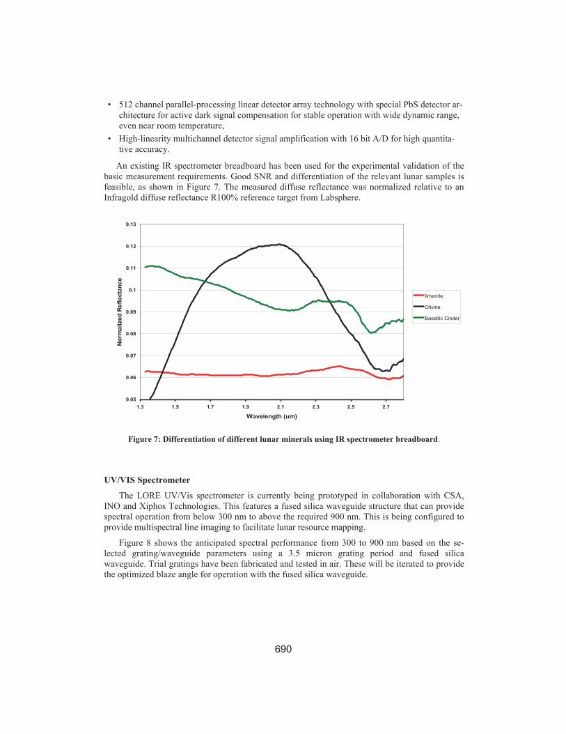
An existing IR spectrometer breadboard has been used for the experimental validation of the basic measurement requirements. Good SNR and differentiation of the relevant lunar samples is feasible, as shown in Figure 7. The measured diffuse reflectance was normalized relative to an Infragold diffuse reflectance R100% reference target from Labsphere.
0.05
0.06
0.07
0.08
0.09
0.1
0.11
0.12
0.13
1.3 1.5 1.7 1.9 2.1 2.3 2.5 2.7
Wavelength (um)
Nor
mal
ized
Ref
lect
ance
Ilmenite
Olivine
Basaltic Cinder
Figure 7: Differentiation of different lunar minerals using IR spectrometer breadboard.
UV/VIS Spectrometer
The LORE UV/Vis spectrometer is currently being prototyped in collaboration with CSA, INO and Xiphos Technologies. This features a fused silica waveguide structure that can provide spectral operation from below 300 nm to above the required 900 nm. This is being configured to provide multispectral line imaging to facilitate lunar resource mapping.
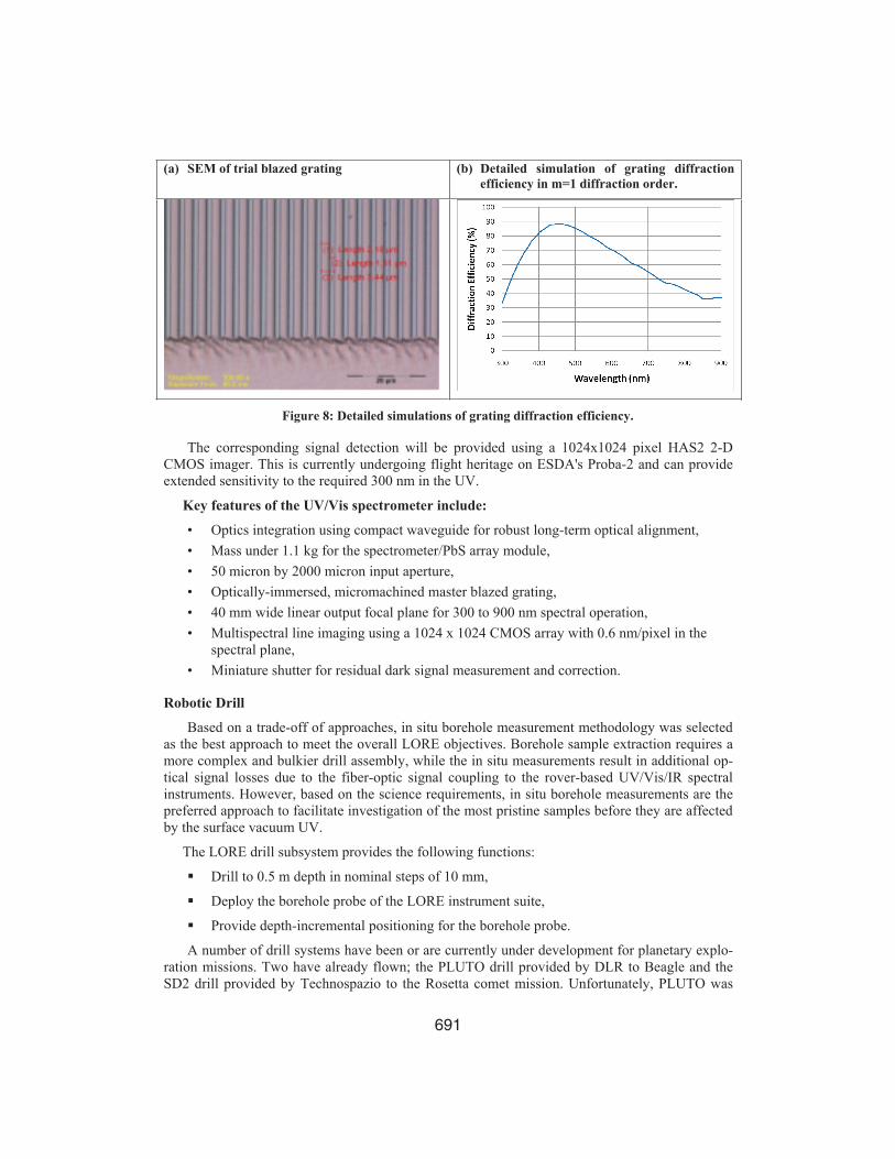
Figure 8 shows the anticipated spectral performance from 300 to 900 nm based on the se-lected grating/waveguide parameters using a 3.5 micron grating period and fused silica waveguide. Trial gratings have been fabricated and tested in air. These will be iterated to provide the optimized blaze angle for operation with the fused silica waveguide.
691
(a) SEM of trial blazed grating (b) Detailed simulation of grating diffraction efficiency in m=1 diffraction order.
Figure 8: Detailed simulations of grating diffraction efficiency.
The corresponding signal detection will be provided using a 1024x1024 pixel HAS2 2-D CMOS imager. This is currently undergoing flight heritage on ESDA's Proba-2 and can provide extended sensitivity to the required 300 nm in the UV.
Key features of the UV/Vis spectrometer include:
• Optics integration using compact waveguide for robust long-term optical alignment, • Mass under 1.1 kg for the spectrometer/PbS array module, • 50 micron by 2000 micron input aperture, • Optically-immersed, micromachined master blazed grating, • 40 mm wide linear output focal plane for 300 to 900 nm spectral operation, • Multispectral line imaging using a 1024 x 1024 CMOS array with 0.6 nm/pixel in the
spectral plane, • Miniature shutter for residual dark signal measurement and correction.
Robotic Drill
Based on a trade-off of approaches, in situ borehole measurement methodology was selected as the best approach to meet the overall LORE objectives. Borehole sample extraction requires a more complex and bulkier drill assembly, while the in situ measurements result in additional op-tical signal losses due to the fiber-optic signal coupling to the rover-based UV/Vis/IR spectral instruments. However, based on the science requirements, in situ borehole measurements are the preferred approach to facilitate investigation of the most pristine samples before they are affected by the surface vacuum UV.
The LORE drill subsystem provides the following functions:
Drill to 0.5 m depth in nominal steps of 10 mm,
Deploy the borehole probe of the LORE instrument suite,
Provide depth-incremental positioning for the borehole probe.
A number of drill systems have been or are currently under development for planetary explo-ration missions. Two have already flown; the PLUTO drill provided by DLR to Beagle and the SD2 drill provided by Technospazio to the Rosetta comet mission. Unfortunately, PLUTO was

692
lost during the Beagle landing failure. The Rosetta drill will not be deployed until 2014 when the spacecraft rendezvous with Comet Churyumov-Gerasimenko. A third drill system currently under flight development is the MSL Drill being developed by JPL. If launched as part of the MSL pay-load, the MSL Drill could well be the first drill system to be used extraterrestrially since the manually operated drills used by the Apollo lunar missions.
The robotic drill element of the proposed Selene-2 LORE payload will support the instrument suite by providing access to subsurface samples. By implementing this drill as part of an integrated instrument package capable of downhole in-situ analysis, the need for sample extraction can be eliminated, thereby simplifying the drill system and minimizing time between drilling and sample analysis. This is especially advantageous to study any volatiles that may be trapped in the lunar subsurface.
The major design drivers for the robotic drill subsystem are:
• Drilling depth – To support the in-situ measurement objectives, the drill should be capable of drilling down to depths of approximate 0.5 m.
• Material – For the anticipated mission location, the drill will be required to penetrate loose lunar regolith, The cohesion of this regolith can vary from as low as 0.5 kPa at shallow depths to 3 kPa at depths of 30-60 cm (for lunar mare regolith).
• Mass and volume – Considering that the target rover mass for Selene-2 is only 30kg, mass will be a major design driver for the drill subsystem. The stowed and operational volume limitations must support overall rover architecture, including the need to deploy the drill system to the lunar surface from the rover platform.
• In situ optical probe accommodation and fiber-optic links to the rover instrument suite.
The rover mass not only drives the subsystem mass requirement but also puts limitations on the allowable drill bit weight-on-bit, related to the ability of the rover system to react thrust for solid drill string drill architectures and the ability of the bore hole stabilization system to react load against the bore wall.
The drill penetration rates must support the mission time-line, rover peak and average power, landing site daylight hours and available thrust for efficient drilling. Based on the mission timelines identified for the drill and in-situ instrument suite for the Mars Inukshuk rover concept17, a penetration rate of 5 mm/s should be sufficient to support the instrument package measurement objectives.
Terrestrial drill systems use ‘drill mud’ (water, gas) to flush the drill face for bit cooling and to remove drill cuttings. For a lunar mission with limited resources (particularly mass and power), the use of fluids for flushing is not feasible. For this reason dry drilling is preferred. There are two major approaches that can be considered for a medium depth (> 20 cm and < 2m) drill – rotary percussive and rotary drag bit.
The use of a rotary-percussive drill will minimize the required weight-on-bit for the system and provide a solution which allows flexibility in stowed volume. This type of drill subsystem was developed as part of the Inukshuk Mars mission Phase 0 concept study performed for the Canadian Space Agency by MPBC, MDA and the University of Winnipeg17.
Walking of the assembly either down or up the bore hole is achieved through driving the sets of anchor pads to apply a normal force to secure the unit against the deployment tube or borehole (see Figure 9b). The pads are sized to distribute the anchor load against the hole without com-promising borehole stability. A weight-on-bit (WOB) assembly is used to apply a load to the Lower Anchor assembly, forcing it downwards to apply force at the drill tip (when in soil) and lengthening the anchor unit as drilling progresses. Once the Lower Anchor is engaged, the Upper

693
Anchor pads are released and the WOB actuator is driven in reverse to retract the Upper Anchor housing, shortening the entire anchor assembly. Near the end of travel of the WOB assembly, the Upper Anchor is re-engaged and the Lower Anchor is retracted. This process can be repeated to “walk” the assembly down the borehole or deployment tube. To “walk” up the hole, the process is done in reverse.
Figure 9: (a) Preliminary schematic of MPBC bore-hole probe (24 mm O.D. x 120 mm long).
Figure 9: (b) Schematic of MDA lunar drill with drill deployment unit and accommodation for the bore-hole probe.
During the drilling, the telemetry includes the motor current, drill depth and drill bit tempera-ture. The rate of penetration data will be used to provide information on the rock strength and regolith cohesion. If there is some uncertainty, the drill will be retracted and the hole examined visually prior to full deployment of the drill.
Subsurface in-situ measurements will be provided using a miniature fiber-optic probe that can be accommodated directly into the lunar drill down-hole module. Figure 9a shows a preliminary schematic of the borehole probe. It is about 24 mm O.D. by 120 mm long, with a net mass under 150 gm. The probe can be integrated within the drill unit with a fiber-optic coupling to the UV/VIS/IR spectrometer on the Selene-2 rover or lander.
The probe incorporates a miniature wafer-level CMOS color camera with 640 x 480 pixels to image the bore-hole stratigraphy and grain size. A lab breadboard of the camera has been set-up and experimentally evaluated.
Illumination will be provided using an array of UV/Vis and IR LEDs to strategically illumi-nated the spectral bands of key interest for the associated science studies. It is proposed to di-

694
rectly incorporate a VIS micro-imager and LED illumination into the probe. For coupling the re-sulting spectral signal back into the spectrometer, a low-loss IRguide fluoride fiber was selected. This provides spectral transmittance from below 300 nm to above 3500 nm with attenuation be-low 0.5 dB/m.
Preliminary testing of the spectrometer optical coupling was performed using an existing IR waveguide spectrometer breadboard and a 2 m long IRguide fiber with 600 micron core (see Fig-ure 10a). Figure 10b shows the corresponding spectrum as measured for a gypsum spectrum with the characteristic O-H band near 1400 nm and H2O band near 1900 nm.
(a) (b)
Figure 10: (a) Spectral attenuation of IRguide optical fiber and (b) experimental validation of fiber-coupled diffuse reflectance measurements using a gypsum sample.
Payload Control
The LORE payload leverages the advanced fault-tolerant, space-grade microprocessor-based data acquisition and control electronics that have been developed in collaboration with Xiphos Technologies and CSA for the Fiber Sensor Demonstrator (FSD)18 on ESA’s Proba-2. This was launched successfully in the fall of 2009 and flight operations have started up with about 10 months of flight time already accumulated.
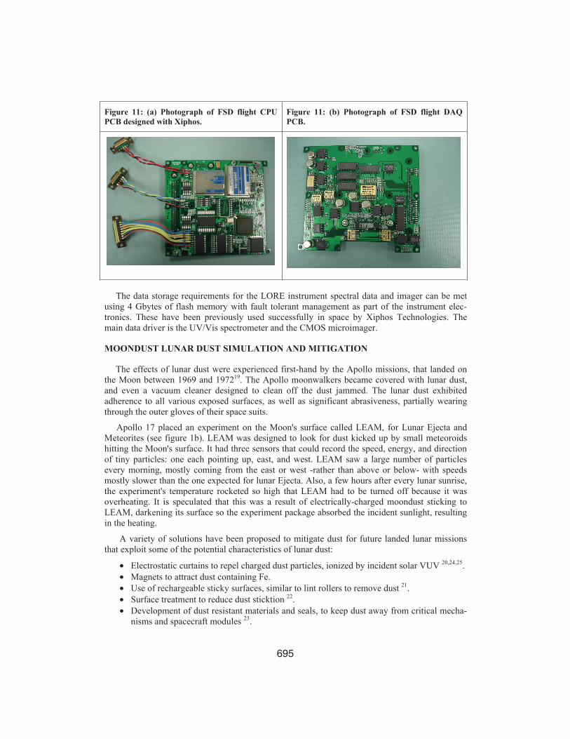
Figure 11a shows a photograph of the flight CPU PCB. This features a spacegrade DC-DC converter from Interpoint and FPGA from Xilinx, as well as the Xiphos latch-up protection for the DC power lines. Data and command I/O is provided using redundant RS422 differential re-ceivers and drivers. The CPU PCB also contains 768 kbytes of SRAM.
The multichannel analog signal processing PCB (see Figure 11b) uses a 16 bit A/D converter from Maxwell with 24 multiplexed analog signal lines and filtered preamplifiers for various sen-sors, including a Radfet for received radiation total dose monitoring. The PCB will provide 4 Gbytes of low-power flash memory with fault-tolerant memory management for the VIS imager data. The electronics have undergone 3-axis random vibration to 16.2 g rms and TVAC operation from -40 to +60oC.
695
Figure 11: (a) Photograph of FSD flight CPU PCB designed with Xiphos.
Figure 11: (b) Photograph of FSD flight DAQ PCB.
The data storage requirements for the LORE instrument spectral data and imager can be met using 4 Gbytes of flash memory with fault tolerant management as part of the instrument elec-tronics. These have been previously used successfully in space by Xiphos Technologies. The main data driver is the UV/Vis spectrometer and the CMOS microimager.
MOONDUST LUNAR DUST SIMULATION AND MITIGATION
The effects of lunar dust were experienced first-hand by the Apollo missions, that landed on the Moon between 1969 and 197219. The Apollo moonwalkers became covered with lunar dust, and even a vacuum cleaner designed to clean off the dust jammed. The lunar dust exhibited adherence to all various exposed surfaces, as well as significant abrasiveness, partially wearing through the outer gloves of their space suits.
Apollo 17 placed an experiment on the Moon's surface called LEAM, for Lunar Ejecta and Meteorites (see figure 1b). LEAM was designed to look for dust kicked up by small meteoroids hitting the Moon's surface. It had three sensors that could record the speed, energy, and direction of tiny particles: one each pointing up, east, and west. LEAM saw a large number of particles every morning, mostly coming from the east or west -rather than above or below- with speeds mostly slower than the one expected for lunar Ejecta. Also, a few hours after every lunar sunrise, the experiment's temperature rocketed so high that LEAM had to be turned off because it was overheating. It is speculated that this was a result of electrically-charged moondust sticking to LEAM, darkening its surface so the experiment package absorbed the incident sunlight, resulting in the heating.
A variety of solutions have been proposed to mitigate dust for future landed lunar missions that exploit some of the potential characteristics of lunar dust:
• Electrostatic curtains to repel charged dust particles, ionized by incident solar VUV 20,24,25.• Magnets to attract dust containing Fe.• Use of rechargeable sticky surfaces, similar to lint rollers to remove dust 21.• Surface treatment to reduce dust sticktion 22.• Development of dust resistant materials and seals, to keep dust away from critical mecha-
nisms and spacecraft modules 23.

696
The Apollo 17 astronauts used duct tape to help cope with the lunar dust 10. One proposed ap-proach is a rechargeable sticky roller to remove dust from surfaces.
MoonDust16 is a project being performed in collaboration with the Canadian Space Agency to study the effects of lunar dust on optics and mechanics elements, and to develop innovative mi-cro/nano-filtration solutions to extend their operational lifetime within a lunar environment.
To assist this work, a small lunar environment simulation vacuum chamber is being set up at MPBC to enable the study of lunar dust effects on optics and rotary mechanisms (see Figure 12). The simulation chamber includes filtered, oil-free vacuum pumping to below 10-6 Torr, an injec-tion system for lunar dust simulants, UV source for vacuum UV (VUV), and diagnostic ports for relevant optical and electrical measurements.
(a) Schematic of the MoonDust lunar simulator vacuum chamber.
(b) Photograph of the main chamber showing win-dows for dust UV irradiation and to enable spec-tral measurements of levitated dust.
Figure 12: MoonDust Lunar dust simulator vacuum chamber at MPBC.
The lunar dust simulator chamber features all stainless-steel construction using UHV-grade conflat flanges. Oil-free pumping is provided using a turbomolecular pump, backed by a molecu-lar drag pump. A high throughput fine particulate filter is fitted between the chamber and the pumping system. Moreover, a bellows-sealed valve can be used to isolate the simulator chamber when dust is being injected, to further protect the pumping system.
The lunar dust simulator chamber features an internal 3" O.D. sieve dust shaker to provide a stream of fine dust particles onto the test device. Different sieve apertures can be selected in the micron range to assess the corresponding effects on small optics elements and mechanical joints.
One of the optical ports is being used for the UV excimer laser source, currently operated at an emission wavelength of 193 nm, to provide VUV excitation and charging of the lunar dust as it falls onto the test device. Additional ports facilitate spectral measurements of the dust and charge measurements using a biased Langmuir probe for spatially-resolved information and a Faraday cup.
The test device is mounted to fixtures in the bottom flange. There are additional electrical feedthroughs to operate vacuum compatible motors, and for the readout of additional sensors to probe accurately the amount of accumulated dust, optics/ mechanics temperatures, etc.
697
Samples of actual lunar dust, as returned by the prior NASA Apollo missions, are being stud-ied under controlled conditions, to develop the detailed requirements for suitable lunar dust simu-lants, in terms of nano-phase Fe content, particle size distributions and shapes, relevant optical and mechanical characteristics. This is being used to assist the formulation of suitable simulants for optics and mechanics elements.
MoonDust is taking a multithrust approach to lunar dust:
1. high-vacuum grade lunar simulator chamber of relevant lunar environment conditions (VUV, dust, vacuum).
2. development of suitable lunar dust simulants relevant to optics and mechanical joints, fo-cusing on a suitable simulant for glass and amorphous silicon-rich grain coatings contain-ing nano-phase Fe (as opposed to separate silica and Fe-bearing particles).
3. development of dust filtration and deflection methods for local control of lunar dust suit-able for operation in vacuum environments based on polymer/carbon nanotube nanocom-posite materials.
The dust mitigation is being applied to the protection of small optical elements and rotary me-chanical joints. The ultimate goal is to develop methodologies that do not require, ideally, any external power for their functional operation.
The MoonDust mitigation solution exploits key characteristics of the lunar dust, the electric charging and ferromagnetism properties, and incorporates nano-filtration based on carbon nano-tube technologies. The aim is to minimize the required consumables and voltages (i.e., low power requirements, and ideally, to avoid completely the need of any external energies sources), while providing high capacity and high efficiencies for filtering and trapping the particles, especially the more dangerous submicron-sized grains.
The LORE dust protection requirements include the 25 mm input aperture for the instrument stand-off optics. This will employ a switched protective sapphire window to act conjointly as a protective cover for the stand-off optics, and as a dust collector to enable in situ studies of the levitated lunar dust.
CONCLUSIONS
LORE complements key planetary science and technology themes, addressing both science issues (e.g., lunar surface geology, trapped volatiles and evolution), surface operation issues (e.g., nature of lunar dust and regolith, electrostatic dust levitation), and lunar usage issues (e.g., identification of key lunar in situ resources: hydrogen and ilmenite). In the context of a lander, and specifically Selene-2, it is also designed to serve as a crucial “calibration point” of “ground truth” for orbiters to provide a robust link to actual ground conditions.
For space-based systems, the important drivers are reliability, power consumption, mass and simplicity of operation. New planetary science and exploration is enabled through groundbreaking miniaturized 300 to 3300 nm UV/VIS/IR instrument technologies for planetary exploration based on MPBC’s patented IOSPEC guided-wave miniature spectrometers, coupled with an extendible MDA micro-robotic mole drill to provide a net rover/lander instrument/drill payload mass under 11 kg.

698
ACKNOWLEDGMENTS
The financial assistance of the Canadian Space Agency is greatly appreciated. The constructive suggestions of Bernard Marsan, Éric Martin, Éric Vachon, Shen-En Qian and Wanping Zheng are gratefully acknowledged.
Special thanks to Daniel Asselin from INO for the spectrometer grating absolute diffraction efficiency simulations.
NOTATION
CSA Canadian Space Agency M3 Moon Mineralogy Mapper
FWHM Full Width Half Maximum MPBC MPB Communications Inc.
JAXA Japan Aerospace Exploration Agency
SELENE Selenological and Engineering Ex-plorer
IOSPEC Integrated Optical Spec-trometer
SNR Signal to Noise Ratio
IR Infrared UV Ultraviolet
LORE Lunar Origins and Resource Explorer
Vis Visible
LRO Lunar Reconnaissance Or-biter
WOB Weight on Bit
REFERENCES
1 P. G. Lucey, G. J. Taylor, B. R. Hawke, and P. D. Spudis, “FeO and TiO2 concentrations in the South Pole-Aitken basin - Implications for mantle composition and basin formation,” Journal of Geophysical Research, 103, 3701-3708 (1998).2 T. M. Matsunaga, M. Ohtake, J. Haruyama, Y. Ogawa1, Y. Yokota, T. Morota, C. Honda, M. Torii, R. Nakamura, S. Kodama3, and LISM Working Group. “Kaguya (SELENE) / Spectral Profiler: In-flight performance and future plan,” Lunar and Planetary Science XXXIX, paper 2226 (2008). 3 C. M. Pieters, and 28 co-authors, “Character and spatial distribution of OH/H2O on the surface of the Moon seen by M3 on Chandrayaan-1,” Science 326, pp. 568-572 (2009). 4 E. Libowitzky and A. Beran, “IR spectroscopic characterization of hydrous species in minerals. In Spectroscopic Methods in Mineralogy,” edited by A. Beran and E. Libowitzky, 227-279, Eotvos University Press, Budapest, Hungary (2004).5 lcross.arc.nasa.gov/mission.htm.6 T. Hashimoto., T. Hoshino, S. Tanaka, K. Matsumoto and J. Kawaguchi, “Japanese Moon Landing Mission SELENE-2,” ISTS (2008). 7 R. V. Kruzelecky, B. Wong, E. Haddad, W. Jamroz, E. Cloutis, N. Ghafoor and S. Jessen, “In Situ Planetary Resource Exploration using Miniature Robotic Subsurface Sample Analysis,” 39th International Conference on Environmental Systems, 2009-09-2528, Savannah (2009). 8 V. G. Kaydash, P. C. Pinet, D. Baratoux, S. Besse, A. Jehl, and S. Chevrel, “Lunar photometry from Clementine mul-tiangular data: Analysis of Hapke parameters estimate and implication for upcoming Smart-1 spot-pointing data,” Lu-nar and Planetary Science, 37, abstract #1692 (2006).

699
9 K. R. Kuhlman, G. L. Kulcinski, and H. H. Schmitt, “Simulation of helium-3 extraction from lunar ilmenite,” Space Resources Roundtable VI, abstract #6044 (2004). 10 Yoshida, H., T. Watanabe, H. Kanamori, T. Yoshida, S. Ogiwara, and K. Eguchi, “Experimental study on water pro-duction by hydrogen reduction of lunar soil stimulant in a fixed bed reactor,” Space Resource Roundtable II, abstract #7009 (2000). 11 J. B. Adams, and T. B. McCord, “Alteration of lunar optical properties: Age and composition effects,” Science, 171, 567-571 (1972). 12 C. M. Pieters, “Compositional diversity and stratigraphy of the lunar crust derived from reflectance spectroscopy,” In Remote Geochemical Analysis: Elemental and Mineralogical Composition, edited by C.. M. Pieters and P. A. J. Englert, 309-339, Cambridge University Press, Cambridge, UK (1993). 13 L. Elkins-Tanton, B. H. Hager, and T. L. Grove, “Magmatic effects of the lunar late heavy bombardment,” Earth and Planetary Science Letters, 222, 17-27 (2004). 14 L. R. Gaddis, C. M. Pieters, and B. R. Hawke, “Remote sensing of lunar pyroclastic mantling deposits,” Icarus, 61, pp. 461-489 (1985). 15 E. A. Cloutis,, K. A. McCormack, J. F. Bell III, A. R. Hendrix, D. T. Bailey, M. A. Craig, S. A. Mertzman, M. S. Robinson, and M. A. Riner, “Ultraviolet spectral reflectance properties of common planetary materials,” Icarus, 197, 321-347. doi: 10.1016/j.icarus.2008.04.018 (2008). 16 R. V. Kruzelecky, B. Wong, B. Aïssa, E. Haddad, W. Jamroz, E. Cloutis, I. D. Rosca, S. V. Hoa, D. Therriault, A. Ellery, “Moondust Lunar Dust Simulation and Mitigation,” 40th International Conference on Environmental Systems, Barcelona (2010). 17 R. V. Kruzelecky, B. Wong, E. Haddad, W. Jamroz, E. Cloutis, N. Ghafoor and S. Jessen, “Inukshuk Landed Robotic Canadian Mission to Mars using a Miniature Sample Analysis Lab for Planetary Mineralogy and Microbiology,” 37th International Conference on Environmental Systems, "2007-01-3104, Chicago (2007). 18 R. V. Kruzelecky, Jing Zou, Najeeb Mohammed, Emile Haddad, Wes Jamroz, Francesco Ricci, Joshua Lamorie, Eric Edwards, Iain McKenzie and Pierrik Vuilleumier, “Fiber-optic Sensor Demonstrator (FSD) for the Monitoring of Spacecraft Subsystems on ESA’s Proba-2,” CASI Astro (2006). 19 J. R. Gaier, “The Effects of Lunar Dust on EVA Systems During the Apollo Missions,” NASA/TM—2005-213610, 2005. http://gltrs.grc.nasa.gov (2005). 20 F. B. Tatom, V. Srepel, R. D. Johnson, N. A. Contaxes, J. G. Adams, H. Seaman and B. L. Cline, “Lunar Dust Degradation Effects and Removal/Prevention Concepts,” NASA Technical Report, TR-792-7-207A (1967). 21 science.nasa.gov/science-news/science-at-nasa/.../21apr_ducttape/; www.newscientist.com/.../dn11326-lint-rollers-may-collect-dangerous-moon-dust.html. 22 C. J. Wohl, M. A. Belcher, J. W. Hopkins and J. W. Connell, “Topographical modifications of materials for lunar dust adhesion mitigation,” 40th Lunar and Planetary Science Conference, Paper 1121 (2009). 23 L. A. Taylor., “Formation of Lunar Dust: Unique Properties for a Human Outpost,” 2008 Joint Annual Meeting, Houston, paper 345-1 (2008). 24 S. Masuda, K. Fujibayashi, K. Ishida and H. Inaba, “Electronic Engineering in Japan,” 92, 9 (1972). 25 C. I. Calle., J. L. McFall, C. R. Buhler, S. J. Snyder, E. E. Arens, A. Chen, M. L. Ritz, J. S. Clements, C. R. Fortier and S. Trigwell, “Dust Particle Removal by Electrostatic and Dielectrophoteric Forces with Applications to NASA Exploration Missions,” Proceeding of ESA Annual Meeting on Electrostatics, Paper 01 (2008).