aashto t-14 2019 agenda items · aashto t-14 2019 agenda items proposed revisions to lrfd bds...
TRANSCRIPT

AASHTO T-142019 Agenda ItemsProposed Revisions to LRFD BDS Section 6
Michael A. Grubb, P.E.
M.A. Grubb & Associates, LLC
Wexford, PA
T-14 Agenda Item No. 27 Section 6, Articles 6.3 and 6.8.2.2
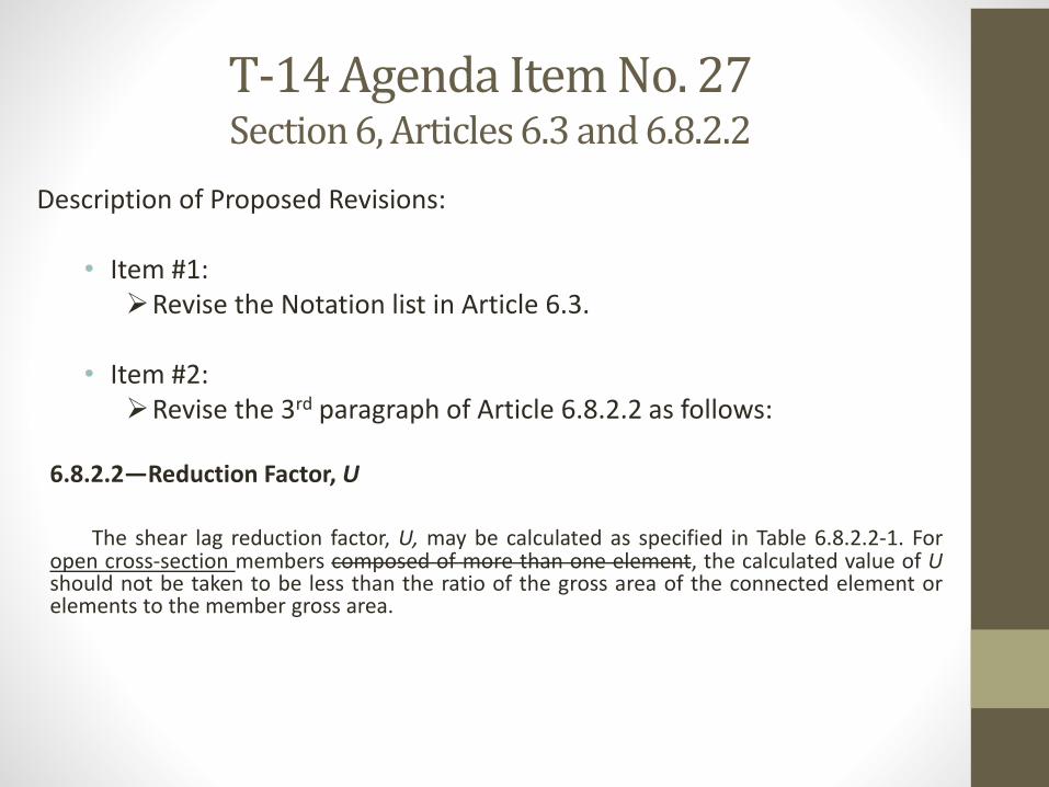
Description of Proposed Revisions:
• Item #1:Revise the Notation list in Article 6.3.
• Item #2:Revise the 3rd paragraph of Article 6.8.2.2 as follows:
6.8.2.2—Reduction Factor, U
The shear lag reduction factor, U, may be calculated as specified in Table 6.8.2.2-1. Foropen cross-section members composed of more than one element, the calculated value of Ushould not be taken to be less than the ratio of the gross area of the connected element orelements to the member gross area.
T-14 Agenda Item No. 27Section 6, Articles 6.3 and 6.8.2.2
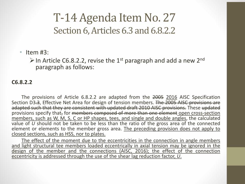
• Item #3: In Article C6.8.2.2, revise the 1st paragraph and add a new 2nd
paragraph as follows:
C6.8.2.2
The provisions of Article 6.8.2.2 are adapted from the 2005 2016 AISC SpecificationSection D3.3, Effective Net Area for design of tension members. The 2005 AISC provisions areadapted such that they are consistent with updated draft 2010 AISC provisions. These updatedprovisions specify that, for members composed of more than one element open cross-sectionmembers, such as W, M, S, C or HP shapes, tees, and single and double angles, the calculatedvalue of U should not be taken to be less than the ratio of the gross area of the connectedelement or elements to the member gross area. The preceding provision does not apply toclosed sections, such as HSS, nor to plates.
The effect of the moment due to the eccentricities in the connection in angle membersand light structural tee members loaded eccentrically in axial tension may be ignored in thedesign of the member and the connections (AISC, 2016); the effect of the connectioneccentricity is addressed through the use of the shear lag reduction factor, U.
T-14 Agenda Item No. 27Section 6, Articles 6.3 and 6.8.2.2
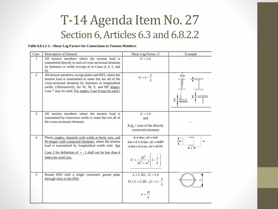
Table 6.8.2.2-1—Shear Lag Factors for Connections to Tension Members
Case Description of Element Shear Lag Factor, U Example
1 All tension members where the tension load is
transmitted directly to each of cross-sectional elements
by fasteners or welds (except as in Cases 3, 4, 5, and
6).
1.0U —
2 All tension members, except plates and HSS, where the
tension load is transmitted to some but not all of the
cross-sectional elements by fasteners or longitudinal
welds. (Alternatively, for W, M, S, and HP shapes,
Case 7 may be used. For angles, Case 8 may be used.)
1x
UL
3 All tension members where the tension load is
transmitted by transverse welds to some but not all of
the cross-sectional elements.
1.0U
and
A An = area of the directly
connected elements
—
4 Plates, angles, channels with welds at heels, tees, and
W-shapes with connected elements, where the tension
load is transmitted by longitudinal welds only. See
Case 2 for definition of x
. L shall not be less than 4
times the weld size.
2 1.0L w U
2 1.5 0.87w L w U
1.5 0.75w L w U
2
2 2
31
3
L xU
LL w
5 Round HSS with a single concentric gusset plate
through slots in the HSS.
1.3 1.0L D U
1.3 1x
D L D UL
Dx
T-14 Agenda Item No. 27Section 6, Articles 6.3 and 6.8.2.2
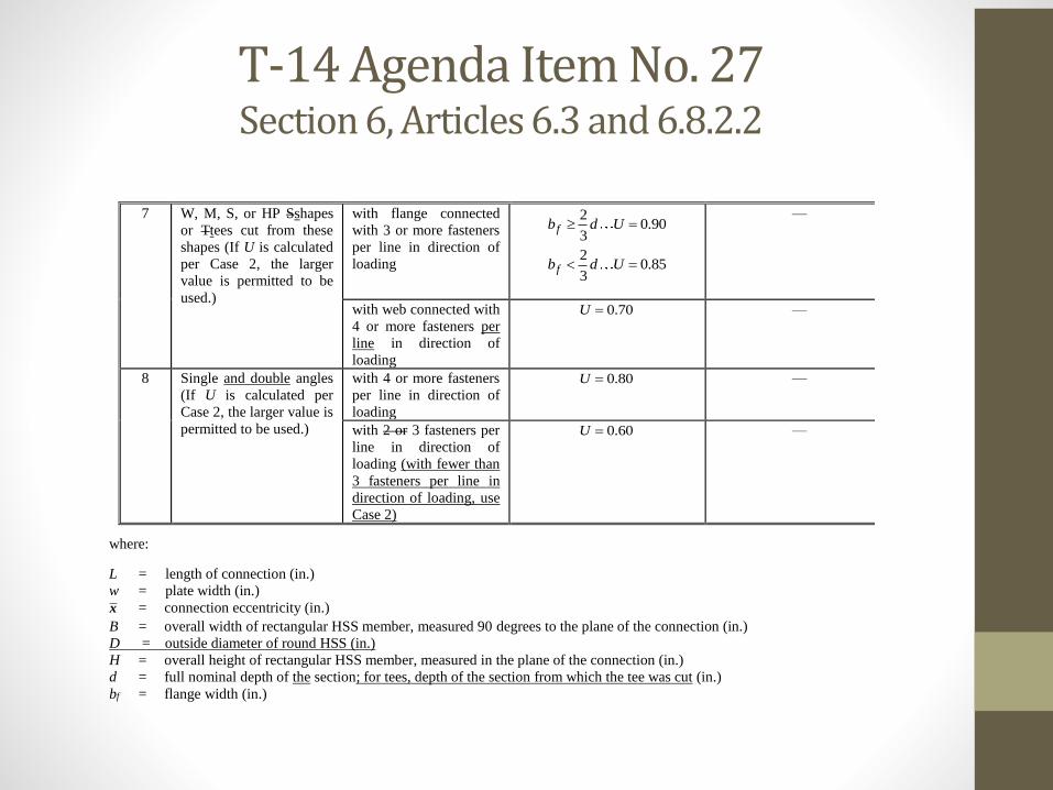
7 W, M, S, or HP Sshapes
or Ttees cut from these
shapes (If U is calculated
per Case 2, the larger
value is permitted to be
used.)
with flange connected
with 3 or more fasteners
per line in direction of
loading
20.90
3fb d U
20.85
3fb d U
—
with web connected with
4 or more fasteners per
line in direction of
loading
0.70U —
8 Single and double angles
(If U is calculated per
Case 2, the larger value is
permitted to be used.)
with 4 or more fasteners
per line in direction of
loading
0.80U —
with 2 or 3 fasteners per
line in direction of
loading (with fewer than
3 fasteners per line in
direction of loading, use
Case 2)
0.60U —
where:
L = length of connection (in.)
w = plate width (in.)
x = connection eccentricity (in.)
B = overall width of rectangular HSS member, measured 90 degrees to the plane of the connection (in.)
D = outside diameter of round HSS (in.)
H = overall height of rectangular HSS member, measured in the plane of the connection (in.)
d = full nominal depth of the section; for tees, depth of the section from which the tee was cut (in.)
bf = flange width (in.)
T-14 Agenda Item No. 28Section 6, Article 6.10.1.4
Description of Proposed Revisions:
• Item #1:Revise Article 6.10.1.4 on Variable Web Depth Members as
follows:
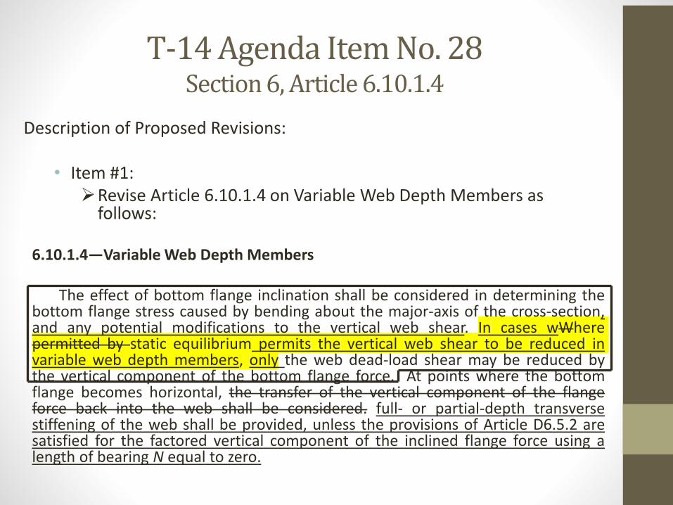
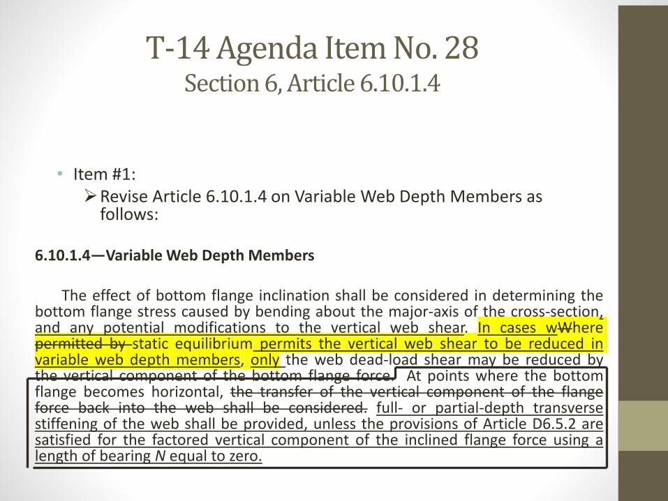
6.10.1.4—Variable Web Depth Members
The effect of bottom flange inclination shall be considered in determining thebottom flange stress caused by bending about the major-axis of the cross-section,and any potential modifications to the vertical web shear. In cases wWherepermitted by static equilibrium permits the vertical web shear to be reduced invariable web depth members, only the web dead-load shear may be reduced bythe vertical component of the bottom flange force. At points where the bottomflange becomes horizontal, the transfer of the vertical component of the flangeforce back into the web shall be considered. full- or partial-depth transversestiffening of the web shall be provided, unless the provisions of Article D6.5.2 aresatisfied for the factored vertical component of the inclined flange force using alength of bearing N equal to zero.
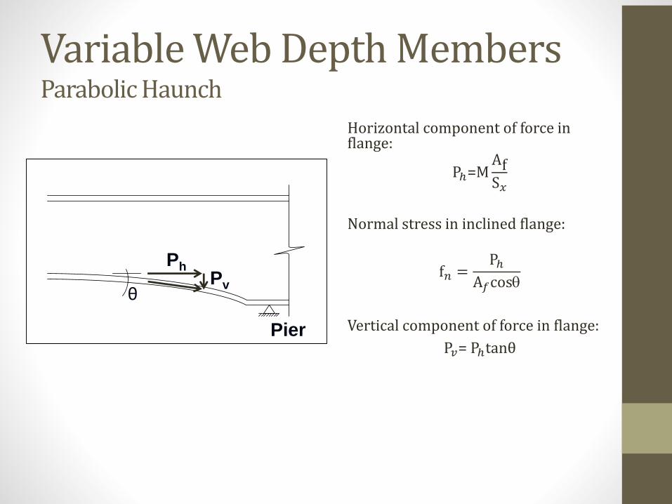
Variable Web Depth MembersParabolic Haunch
Horizontal component of force in flange:
Pℎ=MAfS𝑥
Normal stress in inclined flange:
f𝑛 =Pℎ
A𝑓cos
Vertical component of force in flange:
P𝑣= PℎtanθPier
θ
PhPv
T-14 Agenda Item No. 28 Section 6, Article 6.10.1.4
• Item #2:Revise the 3rd paragraph of Article C6.10.1.4 as follows:
C6.10.1.4
This component of the flange force affects the vertical web shear. In regions ofpositive flexure with tapered or parabolic haunches sloping downward toward thesupports, the vertical web shear is increased by Pv. For fish belly haunches, Pv = 0 nearthe interior supports because the slope of the bottom flange is small in that area. Forall other cases, the vertical web shear is reduced by Pv. In cases where the verticalweb shear is reduced, tThe Specifications permit the Engineer to reduce the webdead-load shear accordingly in these cases. Calculation of the reduced live-load shearis problematic because numerous sets of concurrent moments and shears must beevaluated in order to determine the critical or smallest shear reduction, and thus isnot likely worth the effort. Also, variable depth webs are used most often on longer-span girders where dead load is more predominant. The total modified vertical webshear may be used in the design of the sloping flange-to-web welds.
T-14 Agenda Item No. 28 Section 6, Article 6.10.1.4
• Item #2:Revise the 4th paragraph of Article C6.10.1.4 as follows:
C6.10.1.4
In fish belly haunches, where the slope of the bottom flange is smaller at positionscloser to the interior support, the convex bottom flange in compression produces auniformly distributed radial tensile stress on the web. In parabolic haunches, wherethe downward slope of the bottom flange is larger at positions closer to the interiorsupport, the change in the bottom-flange inclination in combination with compressivestress in the bottom flange induces a compressive distributed transverse force on theweb (Blodgett, 1982) the concave bottom flange in compression produces a uniformlydistributed radial compressive stress on the web. The magnitude of the radial stress ineach case is dependent on the radius of curvature of the flange. Blodgett (1982)provides a rational approach for computing and evaluating the effect of the combinedstresses on the web, which typically are not of significant concern unless the radius ofcurvature of the flange is unusually sharp. If the girder web is unstiffened ortransversely-stiffened with a stiffener spacing do greater than approximately 1.5Dwithin this type of haunch a parabolic haunch adjacent to an interior support, theEngineer should consider checking the stability of the web under this the effect of theradial compressive force.
T-14 Agenda Item No. 28 Section 6, Article 6.10.1.4
• Item #1:Revise Article 6.10.1.4 on Variable Web Depth Members as
follows:
6.10.1.4—Variable Web Depth Members
The effect of bottom flange inclination shall be considered in determining thebottom flange stress caused by bending about the major-axis of the cross-section,and any potential modifications to the vertical web shear. In cases wWherepermitted by static equilibrium permits the vertical web shear to be reduced invariable web depth members, only the web dead-load shear may be reduced bythe vertical component of the bottom flange force. At points where the bottomflange becomes horizontal, the transfer of the vertical component of the flangeforce back into the web shall be considered. full- or partial-depth transversestiffening of the web shall be provided, unless the provisions of Article D6.5.2 aresatisfied for the factored vertical component of the inclined flange force using alength of bearing N equal to zero.
T-14 Agenda Item No. 28 Section 6, Article 6.10.1.4
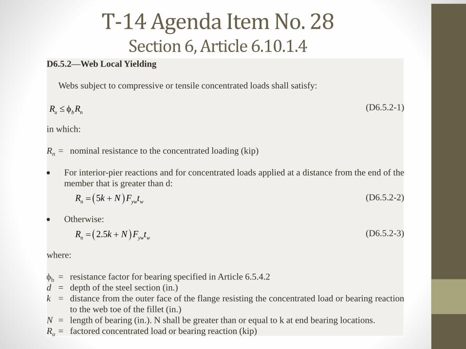
D6.5.2—Web Local Yielding
Webs subject to compressive or tensile concentrated loads shall satisfy:
(D6.5.2-1)
in which:
Rn = nominal resistance to the concentrated loading (kip)
For interior-pier reactions and for concentrated loads applied at a distance from the end of the
member that is greater than d:
(D6.5.2-2)
Otherwise:
(D6.5.2-3)
where:
b = resistance factor for bearing specified in Article 6.5.4.2
d = depth of the steel section (in.)
k = distance from the outer face of the flange resisting the concentrated load or bearing reaction
to the web toe of the fillet (in.)
N = length of bearing (in.). N shall be greater than or equal to k at end bearing locations.
Ru = factored concentrated load or bearing reaction (kip)
u b nR R
5n yw wR k N F t
2.5n yw wR k N F t
T-14 Agenda Item No. 28 Section 6, Article 6.10.1.4
• Item #2:Revise the 5th paragraph of Article C6.10.1.4 as follows:
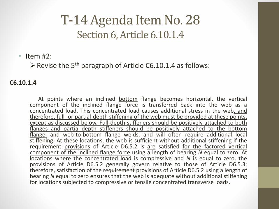
C6.10.1.4
At points where an inclined bottom flange becomes horizontal, the verticalcomponent of the inclined flange force is transferred back into the web as aconcentrated load. This concentrated load causes additional stress in the web, andtherefore, full- or partial-depth stiffening of the web must be provided at these points,except as discussed below. Full-depth stiffeners should be positively attached to bothflanges and partial-depth stiffeners should be positively attached to the bottomflange. and web-to-bottom flange welds, and will often require additional localstiffening. At these locations, the web is sufficient without additional stiffening if therequirement provisions of Article D6.5.2 is are satisfied for the factored verticalcomponent of the inclined flange force using a length of bearing N equal to zero. Atlocations where the concentrated load is compressive and N is equal to zero, theprovisions of Article D6.5.2 generally govern relative to those of Article D6.5.3;therefore, satisfaction of the requirement provisions of Article D6.5.2 using a length ofbearing N equal to zero ensures that the web is adequate without additional stiffeningfor locations subjected to compressive or tensile concentrated transverse loads.
T-14 Agenda Item No. 28Section 6, Article 6.10.1.4
T-14 Agenda Item No. 29Section 6, Articles 6.3 and 6.12.2.2.4
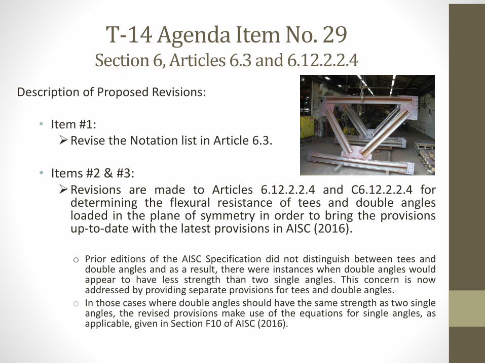
Description of Proposed Revisions:
• Item #1:Revise the Notation list in Article 6.3.
• Items #2 & #3:Revisions are made to Articles 6.12.2.2.4 and C6.12.2.2.4 for
determining the flexural resistance of tees and double anglesloaded in the plane of symmetry in order to bring the provisionsup-to-date with the latest provisions in AISC (2016).
o Prior editions of the AISC Specification did not distinguish between tees anddouble angles and as a result, there were instances when double angles wouldappear to have less strength than two single angles. This concern is nowaddressed by providing separate provisions for tees and double angles.
o In those cases where double angles should have the same strength as two singleangles, the revised provisions make use of the equations for single angles, asapplicable, given in Section F10 of AISC (2016).

T-14 Agenda Item No. 29Section 6, Articles 6.3 and 6.12.2.2.4
• Items #2 & #3: In addition, a new linear transition equation from Mp to My is
introduced for the limit state of lateral-torsional buckling whenthe stem of the member is in tension; that is, when the flange issubject to compression. Previous specifications transitionedabruptly from the full plastic moment to the elastic bucklingrange.
For lateral torsional buckling tee stems and double angle web legs subject to tension, the nominal flexural
resistance based on lateral-torsional buckling shall be taken as:
If Lb ≤ Lp, then lateral-torsional buckling shall not apply.
If Lp < Lb ≤ Lr, then:
b p
n p p yr p
L LM M M M
L L
(6.12.2.2.4c-1)
If Lb > Lr, then:
n crM M (6.12.2.2.4c-2)
T-14 Agenda Item No. 30Section 6, Articles 6.3, 6.13.2.9 and 6.13.6.1.3
Description of Proposed Revisions:
• Item #1:Revise the Notation list in Article 6.3 to catch up with all the
previous revisions made to the provisions for the design of boltedsplices for flexural members.
• Item #2:Add the following paragraph to the end of Article 6.13.2.9:
If the nominal bearing resistance of a bolt hole exceeds the nominal shear resistance ofthe bolt determined as specified in Article 6.13.2.7, the nominal bearing resistance of the bolthole shall be limited to the nominal shear resistance of the bolt.
T-14 Agenda Item No. 30Section 6, Articles 6.3, 6.13.2.9 and 6.13.6.1.3
• Item #3:Revise the 4th paragraph of Article C6.13.2.9 as follows:
In these Specifications, the nominal bearing resistance of an interior hole is based on theclear distance between the hole and the adjacent hole in the direction of the bearing force.The nominal bearing resistance of an end hole is based on the clear distance between the holeand the end of the member. The nominal bearing resistance of the connected member may betaken as the sum of the smaller of the nominal shear resistance of the individual bolts and thenominal bearing resistances of the individual bolt holes parallel to the line of the force. Theclear distance is used to simplify the computations for oversize and slotted holes.
• Item #4:Add the following paragraph underneath Fig. C6.13.6.1.3b-2:
The moment resistance provided by the flanges can potentially be increased by staggering the flange bolts.
T-14 Agenda Item No. 30 Section 6, Articles 6.3, 6.13.2.9 and 6.13.6.1.3
• Item #5:Revise the 1st sentence of the last paragraph of Article
C6.13.6.1.3b as follows:
For flanges with one web in straight girders and for in horizontally curved girders,the effects of flange lateral bending need not be considered in the design of thebolted flange splices since the combined areas of the flange splice plates will typicallyequal or exceed the area of the smaller flange to which they are attached.
• Items #6 & #7:Miscellaneous revisions are made to the changes to Articles
6.13.6.1.3c and C6.13.6.1.3c (Web Splices) that were balloted onand approved in 2017 Agenda Item 16. The revisions are necessaryfor consistency with changes that were previously made to thesearticles in an Errata to the 8th Edition BDS.
T-14 Agenda Item No. 32 Section 6, Various Articles (2)
Description of Proposed Revisions:
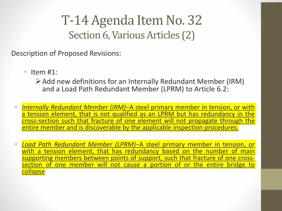
• Item #1:Add new definitions for an Internally Redundant Member (IRM)
and a Load Path Redundant Member (LPRM) to Article 6.2:
• Internally Redundant Member (IRM)−A steel primary member in tension, or witha tension element, that is not qualified as an LPRM but has redundancy in thecross-section such that fracture of one element will not propagate through theentire member and is discoverable by the applicable inspection procedures.
• Load Path Redundant Member (LPRM)−A steel primary member in tension, orwith a tension element, that has redundancy based on the number of mainsupporting members between points of support, such that fracture of one cross-section of one member will not cause a portion of or the entire bridge tocollapse
T-14 Agenda Item No. 32Section 6, Various Articles (2)
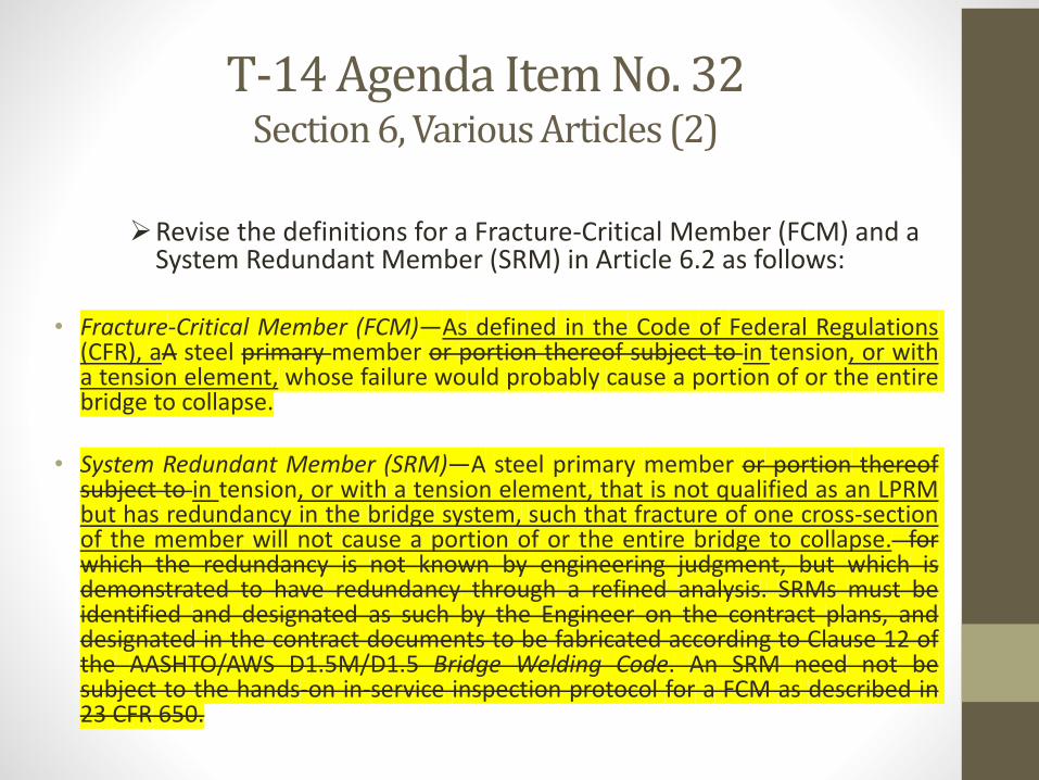
Revise the definitions for a Fracture-Critical Member (FCM) and a System Redundant Member (SRM) in Article 6.2 as follows:
• Fracture-Critical Member (FCM)—As defined in the Code of Federal Regulations(CFR), aA steel primary member or portion thereof subject to in tension, or witha tension element, whose failure would probably cause a portion of or the entirebridge to collapse.
• System Redundant Member (SRM)—A steel primary member or portion thereofsubject to in tension, or with a tension element, that is not qualified as an LPRMbut has redundancy in the bridge system, such that fracture of one cross-sectionof the member will not cause a portion of or the entire bridge to collapse. forwhich the redundancy is not known by engineering judgment, but which isdemonstrated to have redundancy through a refined analysis. SRMs must beidentified and designated as such by the Engineer on the contract plans, anddesignated in the contract documents to be fabricated according to Clause 12 ofthe AASHTO/AWS D1.5M/D1.5 Bridge Welding Code. An SRM need not besubject to the hands-on in-service inspection protocol for a FCM as described in23 CFR 650.
T-14 Agenda Item No. 32 Section 6, Various Articles (2)
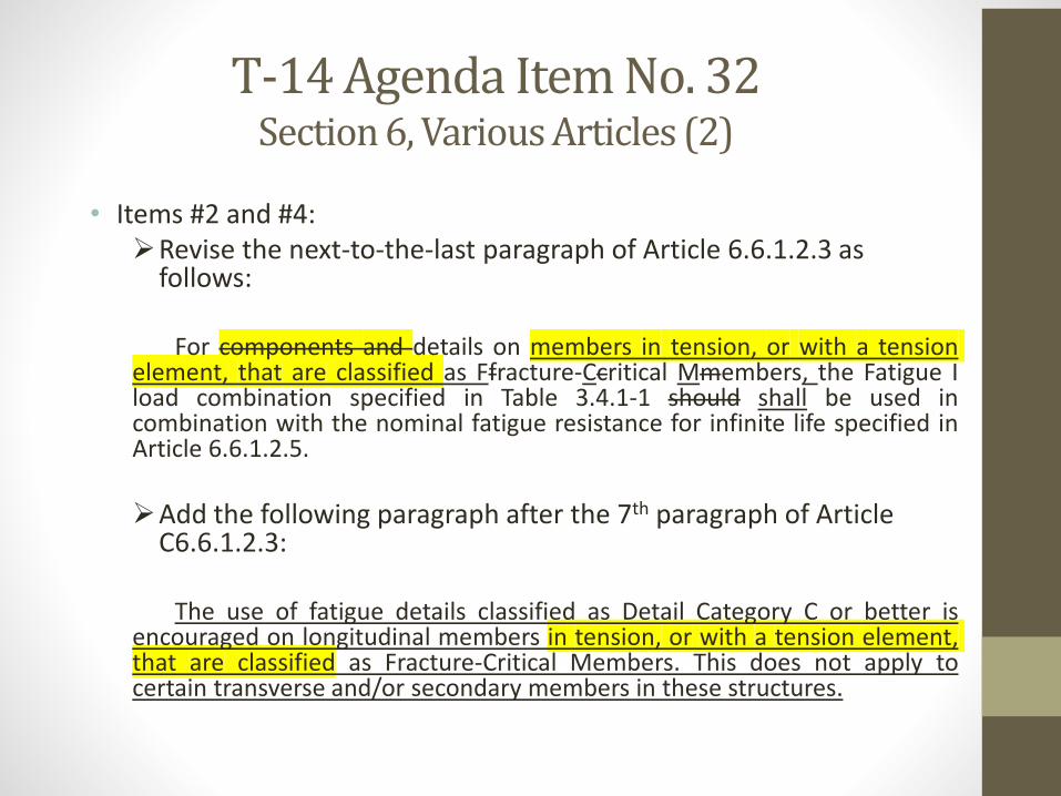
• Items #2 and #4:Revise the next-to-the-last paragraph of Article 6.6.1.2.3 as
follows:
For components and details on members in tension, or with a tensionelement, that are classified as Ffracture-Ccritical Mmembers, the Fatigue Iload combination specified in Table 3.4.1-1 should shall be used incombination with the nominal fatigue resistance for infinite life specified inArticle 6.6.1.2.5.
Add the following paragraph after the 7th paragraph of Article C6.6.1.2.3:
The use of fatigue details classified as Detail Category C or better isencouraged on longitudinal members in tension, or with a tension element,that are classified as Fracture-Critical Members. This does not apply tocertain transverse and/or secondary members in these structures.
T-14 Agenda Item No. 32 Section 6, Various Articles (2)
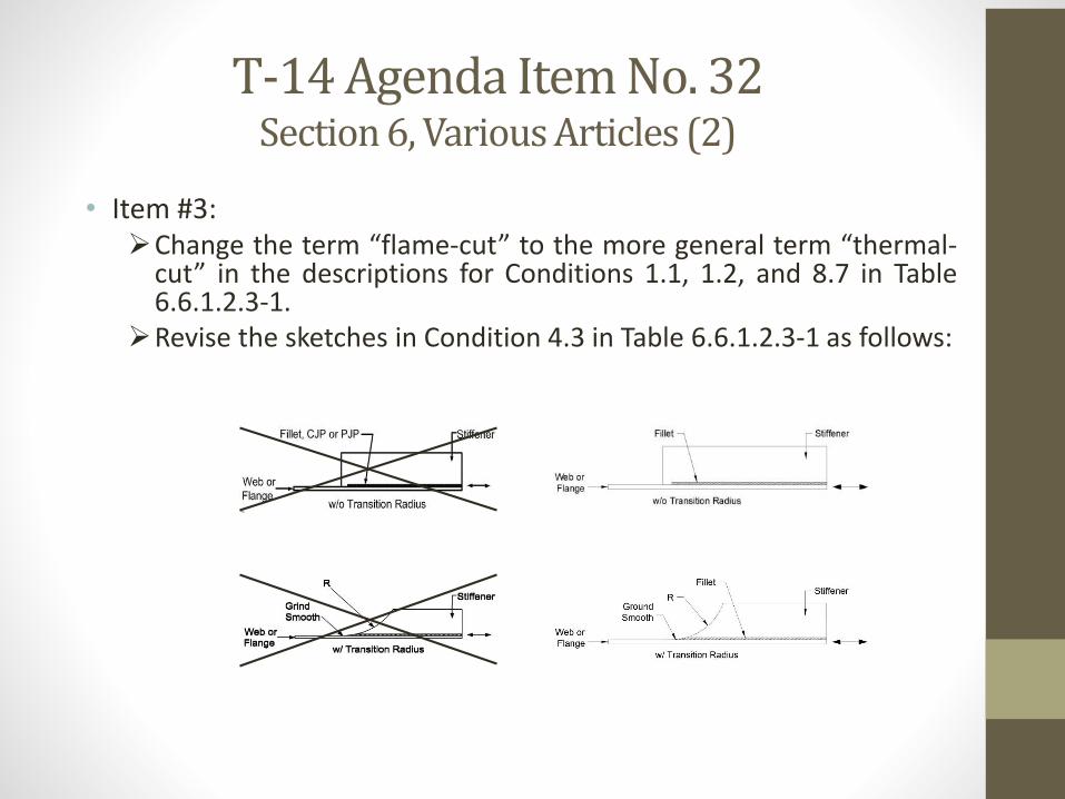
• Item #3:Change the term “flame-cut” to the more general term “thermal-
cut” in the descriptions for Conditions 1.1, 1.2, and 8.7 in Table6.6.1.2.3-1.
Revise the sketches in Condition 4.3 in Table 6.6.1.2.3-1 as follows:
T-14 Agenda Item No. 32 Section 6, Various Articles (2)
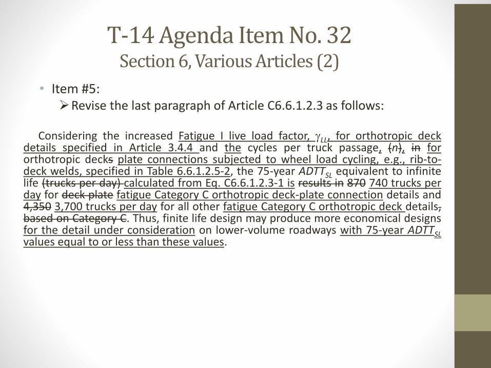
• Item #5:Revise the last paragraph of Article C6.6.1.2.3 as follows:
Considering the increased Fatigue I live load factor, LL, for orthotropic deckdetails specified in Article 3.4.4 and the cycles per truck passage, (n), in fororthotropic decks plate connections subjected to wheel load cycling, e.g., rib-to-deck welds, specified in Table 6.6.1.2.5-2, the 75-year ADTTSL equivalent to infinitelife (trucks per day) calculated from Eq. C6.6.1.2.3-1 is results in 870 740 trucks perday for deck plate fatigue Category C orthotropic deck-plate connection details and4,350 3,700 trucks per day for all other fatigue Category C orthotropic deck details,based on Category C. Thus, finite life design may produce more economical designsfor the detail under consideration on lower-volume roadways with 75-year ADTTSLvalues equal to or less than these values.
T-14 Agenda Item No. 32 Section 6, Various Articles (2)
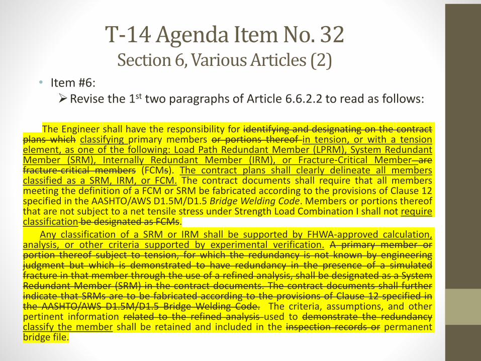
• Item #6:Revise the 1st two paragraphs of Article 6.6.2.2 to read as follows:
The Engineer shall have the responsibility for identifying and designating on the contractplans which classifying primary members or portions thereof in tension, or with a tensionelement, as one of the following: Load Path Redundant Member (LPRM), System RedundantMember (SRM), Internally Redundant Member (IRM), or Fracture-Critical Member arefracture-critical members (FCMs). The contract plans shall clearly delineate all membersclassified as a SRM, IRM, or FCM. The contract documents shall require that all membersmeeting the definition of a FCM or SRM be fabricated according to the provisions of Clause 12specified in the AASHTO/AWS D1.5M/D1.5 Bridge Welding Code. Members or portions thereofthat are not subject to a net tensile stress under Strength Load Combination I shall not requireclassification be designated as FCMs.
Any classification of a SRM or IRM shall be supported by FHWA-approved calculation,analysis, or other criteria supported by experimental verification. A primary member orportion thereof subject to tension, for which the redundancy is not known by engineeringjudgment but which is demonstrated to have redundancy in the presence of a simulatedfracture in that member through the use of a refined analysis, shall be designated as a SystemRedundant Member (SRM) in the contract documents. The contract documents shall furtherindicate that SRMs are to be fabricated according to the provisions of Clause 12 specified inthe AASHTO/AWS D1.5M/D1.5 Bridge Welding Code. The criteria, assumptions, and otherpertinent information related to the refined analysis used to demonstrate the redundancyclassify the member shall be retained and included in the inspection records or permanentbridge file.
T-14 Agenda Item No. 32 Section 6, Various Articles (2)
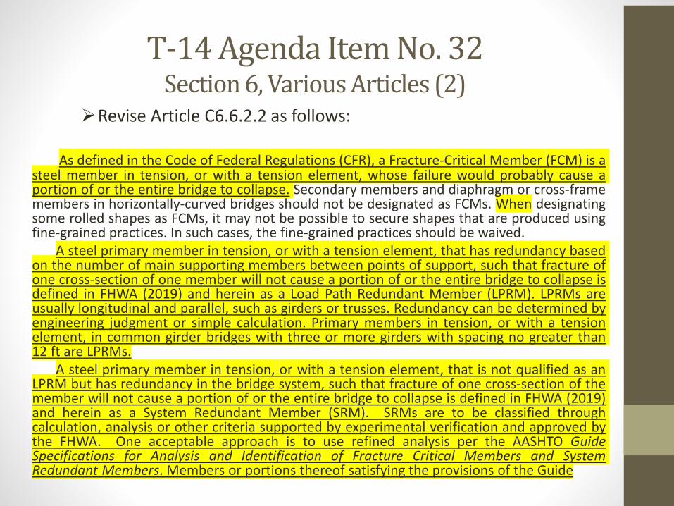
Revise Article C6.6.2.2 as follows:
As defined in the Code of Federal Regulations (CFR), a Fracture-Critical Member (FCM) is asteel member in tension, or with a tension element, whose failure would probably cause aportion of or the entire bridge to collapse. Secondary members and diaphragm or cross-framemembers in horizontally-curved bridges should not be designated as FCMs. When designatingsome rolled shapes as FCMs, it may not be possible to secure shapes that are produced usingfine-grained practices. In such cases, the fine-grained practices should be waived.
A steel primary member in tension, or with a tension element, that has redundancy basedon the number of main supporting members between points of support, such that fracture ofone cross-section of one member will not cause a portion of or the entire bridge to collapse isdefined in FHWA (2019) and herein as a Load Path Redundant Member (LPRM). LPRMs areusually longitudinal and parallel, such as girders or trusses. Redundancy can be determined byengineering judgment or simple calculation. Primary members in tension, or with a tensionelement, in common girder bridges with three or more girders with spacing no greater than12 ft are LPRMs.
A steel primary member in tension, or with a tension element, that is not qualified as anLPRM but has redundancy in the bridge system, such that fracture of one cross-section of themember will not cause a portion of or the entire bridge to collapse is defined in FHWA (2019)and herein as a System Redundant Member (SRM). SRMs are to be classified throughcalculation, analysis or other criteria supported by experimental verification and approved bythe FHWA. One acceptable approach is to use refined analysis per the AASHTO GuideSpecifications for Analysis and Identification of Fracture Critical Members and SystemRedundant Members. Members or portions thereof satisfying the provisions of the Guide
T-14 Agenda Item No. 32 Section 6, Various Articles (2)
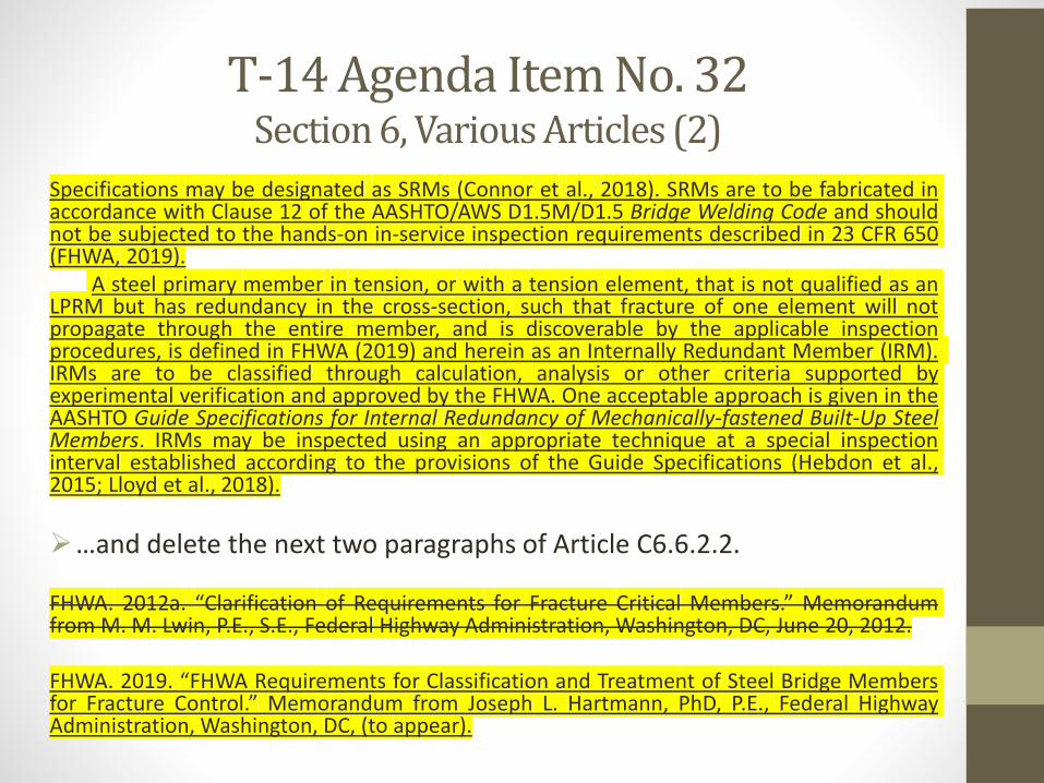
Specifications may be designated as SRMs (Connor et al., 2018). SRMs are to be fabricated inaccordance with Clause 12 of the AASHTO/AWS D1.5M/D1.5 Bridge Welding Code and shouldnot be subjected to the hands-on in-service inspection requirements described in 23 CFR 650(FHWA, 2019).
A steel primary member in tension, or with a tension element, that is not qualified as anLPRM but has redundancy in the cross-section, such that fracture of one element will notpropagate through the entire member, and is discoverable by the applicable inspectionprocedures, is defined in FHWA (2019) and herein as an Internally Redundant Member (IRM).IRMs are to be classified through calculation, analysis or other criteria supported byexperimental verification and approved by the FHWA. One acceptable approach is given in theAASHTO Guide Specifications for Internal Redundancy of Mechanically-fastened Built-Up SteelMembers. IRMs may be inspected using an appropriate technique at a special inspectioninterval established according to the provisions of the Guide Specifications (Hebdon et al.,2015; Lloyd et al., 2018).
…and delete the next two paragraphs of Article C6.6.2.2.
FHWA. 2012a. “Clarification of Requirements for Fracture Critical Members.” Memorandumfrom M. M. Lwin, P.E., S.E., Federal Highway Administration, Washington, DC, June 20, 2012.
FHWA. 2019. “FHWA Requirements for Classification and Treatment of Steel Bridge Membersfor Fracture Control.” Memorandum from Joseph L. Hartmann, PhD, P.E., Federal HighwayAdministration, Washington, DC, (to appear).
T-14 Agenda Item No. 32Section 6, Various Articles (2)
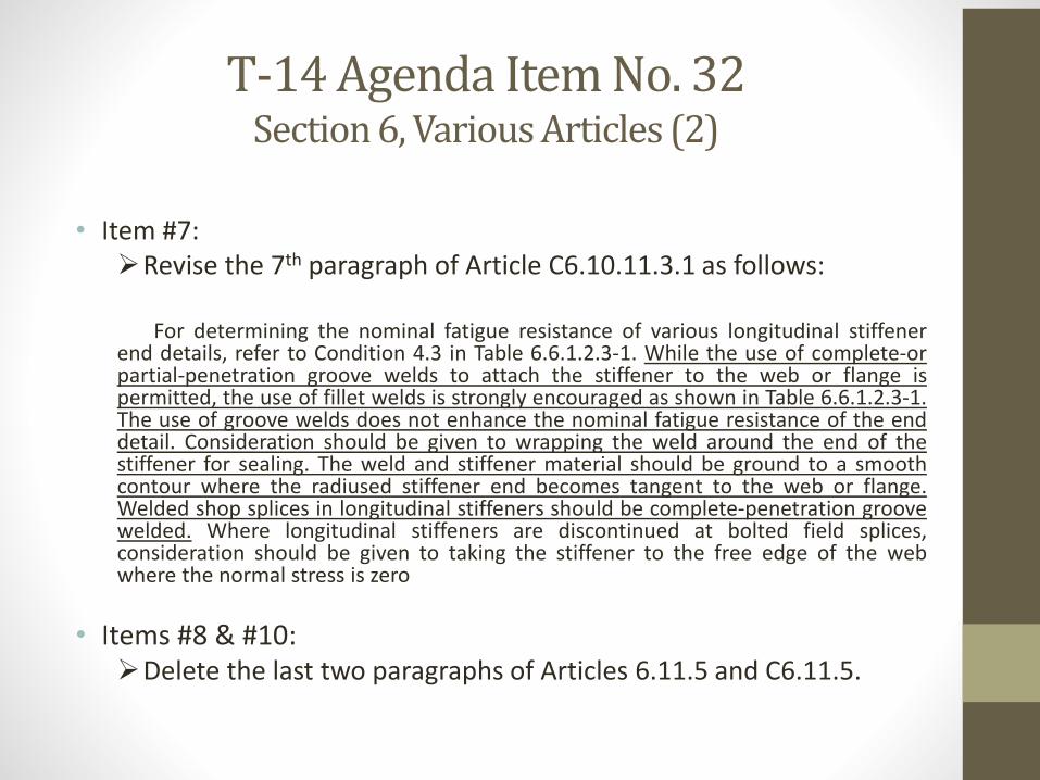
• Item #7:Revise the 7th paragraph of Article C6.10.11.3.1 as follows:
For determining the nominal fatigue resistance of various longitudinal stiffenerend details, refer to Condition 4.3 in Table 6.6.1.2.3-1. While the use of complete-orpartial-penetration groove welds to attach the stiffener to the web or flange ispermitted, the use of fillet welds is strongly encouraged as shown in Table 6.6.1.2.3-1.The use of groove welds does not enhance the nominal fatigue resistance of the enddetail. Consideration should be given to wrapping the weld around the end of thestiffener for sealing. The weld and stiffener material should be ground to a smoothcontour where the radiused stiffener end becomes tangent to the web or flange.Welded shop splices in longitudinal stiffeners should be complete-penetration groovewelded. Where longitudinal stiffeners are discontinued at bolted field splices,consideration should be given to taking the stiffener to the free edge of the webwhere the normal stress is zero
• Items #8 & #10:Delete the last two paragraphs of Articles 6.11.5 and C6.11.5.
T-14 Agenda Item No. 32 Section 6, Various Articles (2)
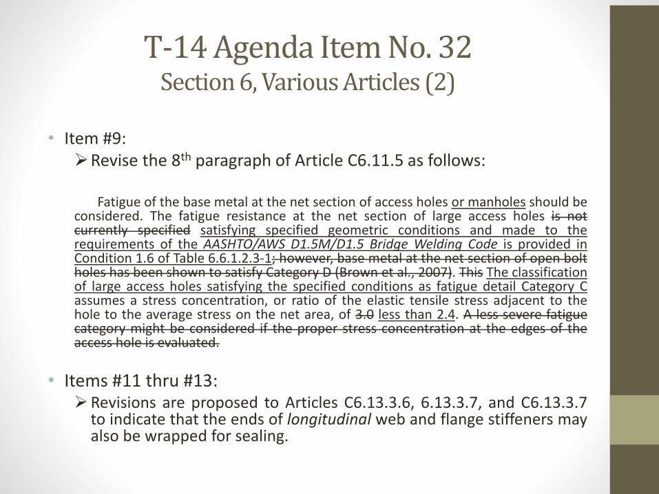
• Item #9:Revise the 8th paragraph of Article C6.11.5 as follows:
Fatigue of the base metal at the net section of access holes or manholes should beconsidered. The fatigue resistance at the net section of large access holes is notcurrently specified satisfying specified geometric conditions and made to therequirements of the AASHTO/AWS D1.5M/D1.5 Bridge Welding Code is provided inCondition 1.6 of Table 6.6.1.2.3-1; however, base metal at the net section of open boltholes has been shown to satisfy Category D (Brown et al., 2007). This The classificationof large access holes satisfying the specified conditions as fatigue detail Category Cassumes a stress concentration, or ratio of the elastic tensile stress adjacent to thehole to the average stress on the net area, of 3.0 less than 2.4. A less severe fatiguecategory might be considered if the proper stress concentration at the edges of theaccess hole is evaluated.
• Items #11 thru #13:Revisions are proposed to Articles C6.13.3.6, 6.13.3.7, and C6.13.3.7
to indicate that the ends of longitudinal web and flange stiffeners mayalso be wrapped for sealing.
T-14 Editorial ItemsLocation of
Change
Current Text Proposed Text
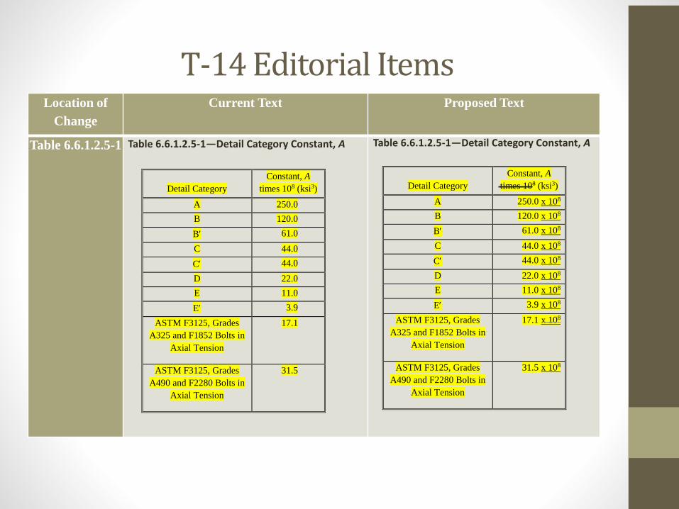
Table 6.6.1.2.5-1 Table 6.6.1.2.5-1—Detail Category Constant, A Table 6.6.1.2.5-1—Detail Category Constant, A
Detail Category
Constant, A
times 108 (ksi3)
A 250.0
B 120.0
B 61.0
C 44.0
C 44.0
D 22.0
E 11.0
E 3.9
ASTM F3125, Grades
A325 and F1852 Bolts in
Axial Tension
17.1
ASTM F3125, Grades
A490 and F2280 Bolts in
Axial Tension
31.5
Detail Category
Constant, A
times 108 (ksi3)
A 250.0 x 10⁸
B 120.0 x 10⁸
B 61.0 x 10⁸
C 44.0 x 10⁸
C 44.0 x 10⁸
D 22.0 x 10⁸
E 11.0 x 10⁸
E 3.9 x 10⁸
ASTM F3125, Grades
A325 and F1852 Bolts in
Axial Tension
17.1 x 10⁸
ASTM F3125, Grades
A490 and F2280 Bolts in
Axial Tension
31.5 x 10⁸
T-14 Editorial Items
Location of
Change
Current Text Proposed Text
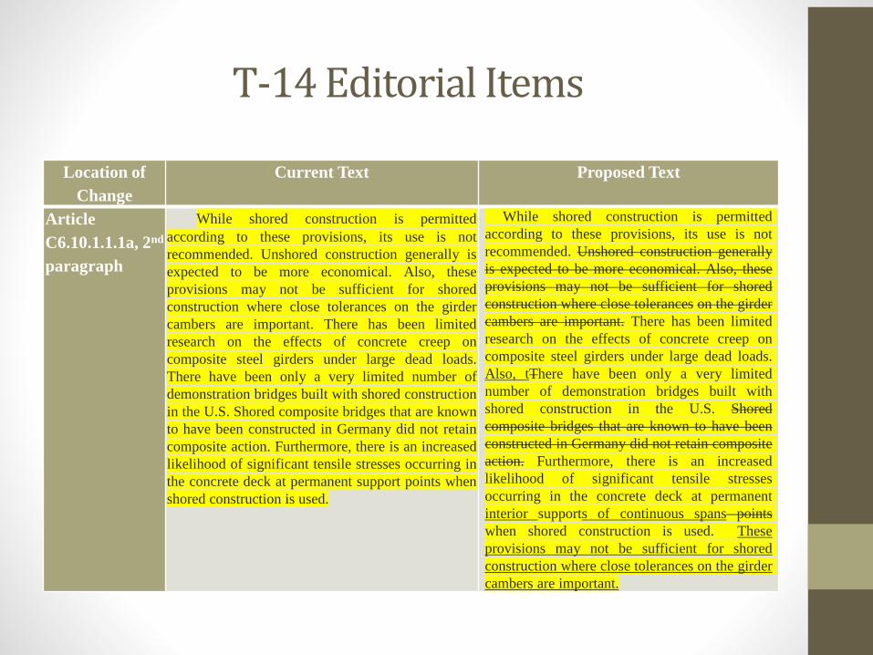
Article
C6.10.1.1.1a, 2nd
paragraph
While shored construction is permitted
according to these provisions, its use is not
recommended. Unshored construction generally is
expected to be more economical. Also, these
provisions may not be sufficient for shored
construction where close tolerances on the girder
cambers are important. There has been limited
research on the effects of concrete creep on
composite steel girders under large dead loads.
There have been only a very limited number of
demonstration bridges built with shored construction
in the U.S. Shored composite bridges that are known
to have been constructed in Germany did not retain
composite action. Furthermore, there is an increased
likelihood of significant tensile stresses occurring in
the concrete deck at permanent support points when
shored construction is used.
While shored construction is permitted
according to these provisions, its use is not
recommended. Unshored construction generally
is expected to be more economical. Also, these
provisions may not be sufficient for shored
construction where close tolerances on the girder
cambers are important. There has been limited
research on the effects of concrete creep on
composite steel girders under large dead loads.
Also, tThere have been only a very limited
number of demonstration bridges built with
shored construction in the U.S. Shored
composite bridges that are known to have been
constructed in Germany did not retain composite
action. Furthermore, there is an increased
likelihood of significant tensile stresses
occurring in the concrete deck at permanent
interior supports of continuous spans points
when shored construction is used. These
provisions may not be sufficient for shored
construction where close tolerances on the girder
cambers are important.
T-14 Editorial ItemsLocation of
Change
Current Text Proposed Text
Article
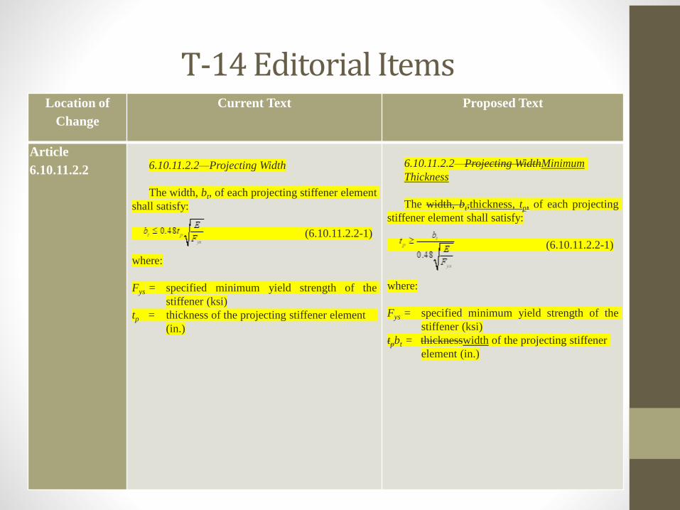
6.10.11.2.2 6.10.11.2.2—Projecting Width
The width, bt, of each projecting stiffener element
shall satisfy:
(6.10.11.2.2-1)
where:
Fys = specified minimum yield strength of the
stiffener (ksi)
tp = thickness of the projecting stiffener element
(in.)
6.10.11.2.2—Projecting WidthMinimum
Thickness
The width, bt,thickness, tp, of each projecting
stiffener element shall satisfy:
(6.10.11.2.2-1)
where:
Fys = specified minimum yield strength of the
stiffener (ksi)
tpbt = thicknesswidth of the projecting stiffener
element (in.)