abb electrical install ti on handbook 4th edition
TRANSCRIPT
8/3/2019 ABB Electrical Install Ti On Handbook 4th Edition
http://slidepdf.com/reader/full/abb-electrical-install-ti-on-handbook-4th-edition 1/322
8/3/2019 ABB Electrical Install Ti On Handbook 4th Edition
http://slidepdf.com/reader/full/abb-electrical-install-ti-on-handbook-4th-edition 2/322
8/3/2019 ABB Electrical Install Ti On Handbook 4th Edition
http://slidepdf.com/reader/full/abb-electrical-install-ti-on-handbook-4th-edition 3/322
8/3/2019 ABB Electrical Install Ti On Handbook 4th Edition
http://slidepdf.com/reader/full/abb-electrical-install-ti-on-handbook-4th-edition 4/322
8/3/2019 ABB Electrical Install Ti On Handbook 4th Edition
http://slidepdf.com/reader/full/abb-electrical-install-ti-on-handbook-4th-edition 5/322
8/3/2019 ABB Electrical Install Ti On Handbook 4th Edition
http://slidepdf.com/reader/full/abb-electrical-install-ti-on-handbook-4th-edition 6/322

8/3/2019 ABB Electrical Install Ti On Handbook 4th Edition
http://slidepdf.com/reader/full/abb-electrical-install-ti-on-handbook-4th-edition 7/322
8 ABB SACE - Protection and control devices
1.1 General aspects
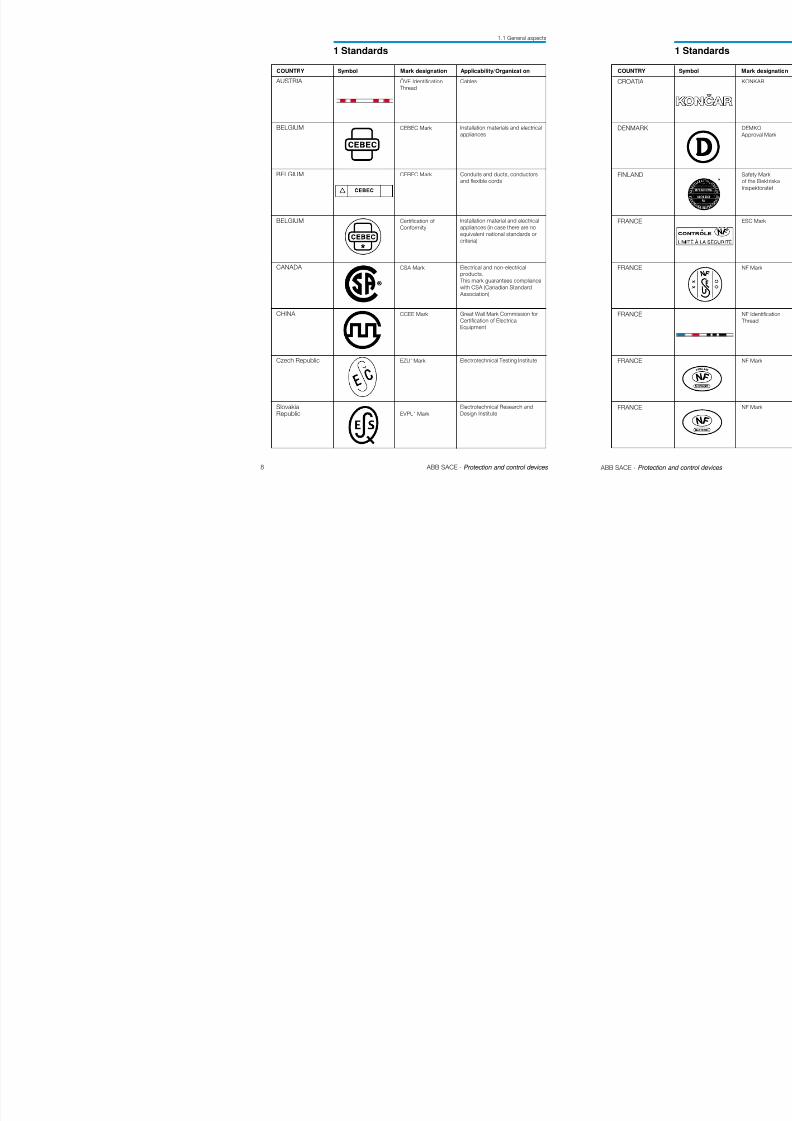
1 Standards
COUNTRY Symbol Mark designation Applicability/Organization
AUSTRIA
BELGIUM
BELGIUM
BELGIUM
CANADA
CHINA
Czech Republic
SlovakiaRepublic
Ö VE Identification
Thread
CEBEC Mark
CEBEC Mark
Certification of
Conformity
CSA Mark
CCEE Mark
EZU’ Mark
EVPU’ Mark
Cables
Installation materials and electrical
appliances
Conduits and ducts, conductors
and flexible cords
Installation material and electrical
appliances (in case there are no
equivalent national standards or
criteria)
Electrical and non-electricalproducts.
This mark guarantees compliance
with CSA (Canadian Standard
Association)
Great Wall Mark Commission for
Certification of Electrical
Equipment
Electrotechnical Testing Institute
Electrotechnical Research and
Design Institute
8/3/2019 ABB Electrical Install Ti On Handbook 4th Edition
http://slidepdf.com/reader/full/abb-electrical-install-ti-on-handbook-4th-edition 8/322
10 ABB SACE - Protection and control devices
1.1 General aspects
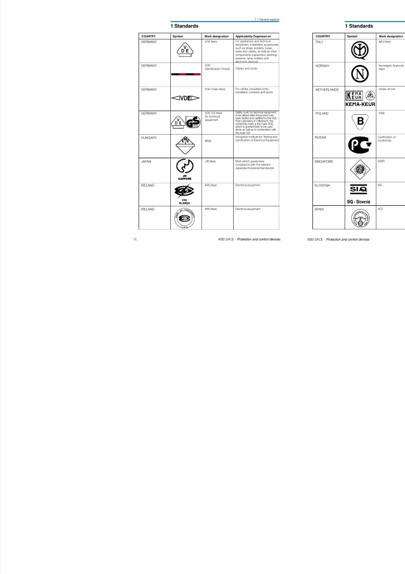
1 Standards
COUNTRY Symbol Mark designation Applicability/Organization
GERMANY
GERMANY
GERMANY
GERMANY
HUNGARY
JAPAN
IRELAND
IRELAND
VDE Mark
VDE
Identification Thread
VDE Cable Mark
VDE-GS Mark
for technical
equipment
MEEI
JIS Mark
IIRS Mark
IIRS Mark
For appliances and technical
equipment, installation accessoriessuch as plugs, sockets, fuses,
wires and cables, as well as other
components (capacitors, earthing
systems, lamp holders and
electronic devices)
Cables and cords
For cables, insulated cords,installation conduits and ducts
Safety mark for technical equipmentto be affixed after the product hasbeen tested and certified by the VDE
Test Laboratory in Offenbach; theconformity mark is the mark VDE,which is granted both to be usedalone as well as in combination withthe mark GS
Hungarian Institute for Testing andCertification of Electrical Equipment
Mark which guarantees
compliance with the relevant
Japanese Industrial Standard(s).
Electrical equipment
Electrical equipment
geprüfte Sicherheit
M A R K
O F CO N F O
R M
I T Y
I . I .R . S.
8/3/2019 ABB Electrical Install Ti On Handbook 4th Edition
http://slidepdf.com/reader/full/abb-electrical-install-ti-on-handbook-4th-edition 9/322
12 ABB SACE - Protection and control devices
1.1 General aspects
1 Standards
COUNTRY Symbol Mark designation Applicability/Organization
SWEDEN
SWITZERLAND
SWITZERLAND
SWITZERLAND
UNITEDKINGDOM
UNITEDKINGDOM
UNITEDKINGDOM
SEMKO
Mark
Safety Mark
–
SEV Safety Mark
ASTA Mark
BASEC Mark
BASECIdentification Thread
Mandatory safety approval for low
voltage material and equipment.
Swiss low voltage material subjectto mandatory approval (safety).
Cables subject to mandatoryapproval
Low voltage material subject to
mandatory approval
Mark which guarantees
compliance with the relevant
“British Standards”
Mark which guarantees
compliance with the “British
Standards” for conductors, cables
and ancillary products.
Cables
C E R T
I F I C
A T I O N T R A D
E M A R K
SPAIN AENOR Asociación Española deNormalización y Certificación.
(Spanish Standarization and
Certification Association)
8/3/2019 ABB Electrical Install Ti On Handbook 4th Edition
http://slidepdf.com/reader/full/abb-electrical-install-ti-on-handbook-4th-edition 10/322
8/3/2019 ABB Electrical Install Ti On Handbook 4th Edition
http://slidepdf.com/reader/full/abb-electrical-install-ti-on-handbook-4th-edition 11/322
8/3/2019 ABB Electrical Install Ti On Handbook 4th Edition
http://slidepdf.com/reader/full/abb-electrical-install-ti-on-handbook-4th-edition 12/322
8/3/2019 ABB Electrical Install Ti On Handbook 4th Edition
http://slidepdf.com/reader/full/abb-electrical-install-ti-on-handbook-4th-edition 13/322
8/3/2019 ABB Electrical Install Ti On Handbook 4th Edition
http://slidepdf.com/reader/full/abb-electrical-install-ti-on-handbook-4th-edition 14/322
8/3/2019 ABB Electrical Install Ti On Handbook 4th Edition
http://slidepdf.com/reader/full/abb-electrical-install-ti-on-handbook-4th-edition 15/322
8/3/2019 ABB Electrical Install Ti On Handbook 4th Edition
http://slidepdf.com/reader/full/abb-electrical-install-ti-on-handbook-4th-edition 16/322
8/3/2019 ABB Electrical Install Ti On Handbook 4th Edition
http://slidepdf.com/reader/full/abb-electrical-install-ti-on-handbook-4th-edition 17/322

8/3/2019 ABB Electrical Install Ti On Handbook 4th Edition
http://slidepdf.com/reader/full/abb-electrical-install-ti-on-handbook-4th-edition 18/322
8/3/2019 ABB Electrical Install Ti On Handbook 4th Edition
http://slidepdf.com/reader/full/abb-electrical-install-ti-on-handbook-4th-edition 19/322
8/3/2019 ABB Electrical Install Ti On Handbook 4th Edition
http://slidepdf.com/reader/full/abb-electrical-install-ti-on-handbook-4th-edition 20/322
8/3/2019 ABB Electrical Install Ti On Handbook 4th Edition
http://slidepdf.com/reader/full/abb-electrical-install-ti-on-handbook-4th-edition 21/322
8/3/2019 ABB Electrical Install Ti On Handbook 4th Edition
http://slidepdf.com/reader/full/abb-electrical-install-ti-on-handbook-4th-edition 22/322

8/3/2019 ABB Electrical Install Ti On Handbook 4th Edition
http://slidepdf.com/reader/full/abb-electrical-install-ti-on-handbook-4th-edition 23/322
8/3/2019 ABB Electrical Install Ti On Handbook 4th Edition
http://slidepdf.com/reader/full/abb-electrical-install-ti-on-handbook-4th-edition 24/322
42 ABB SACE - Protection and control devices
3 General characteristics
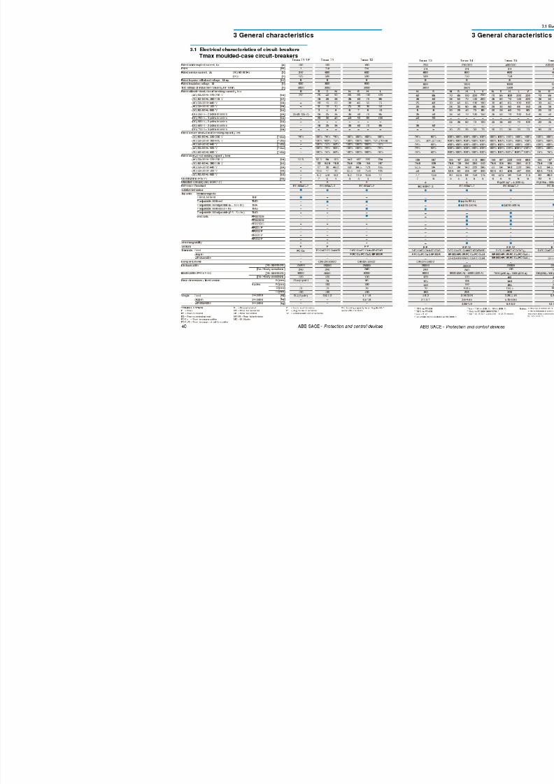
3.1 Electrical characteristics of circuit-breakers
Rated uninterrupted current, Iu [A]
Poles No.Rated operational voltage, Ue (ac) 50-60Hz [V]
(dc) [V]
Rated impulse withstand voltage, Uimp [kV]
Rated insulation voltage, Ui [V]
Test voltage at industrial frequency for 1 min. [V]
Rated ultimate short-circuit breaking capacity, Icu
(ac) 50-60 Hz 220/230 V [kA]
(ac) 50-60 Hz 380/415 V [kA]
(ac) 50-60 Hz 440 V [kA]
(ac) 50-60 Hz 500 V [kA]
(ac) 50-60 Hz 690 V [kA]
(dc) 250 V - 2 poles in series [kA]
(dc) 500 V - 2 poles in series [kA]
(dc) 500 V - 3 poles in series [kA](dc) 750 V - 3 poles in series [kA]
Rated short-circuit service
breaking capacity, Ics [%Icu]
Rated short-circuit making capacity (415 V) Icm [kA]
Opening time (415V at Icu) [ms]
Rated short-time withstand current for 1 s, Icw [kA]
Utilization category (EN 60947-2)
Isolation behaviour
IEC 60947-2, EN 60947-2
Releases: thermomagnetic T adjustable, M adjustable TMA
T adjustable, M fixed 2,5 In TMG
wi th microprocessor PR211/P (I-LI)
PR212/P (LSI-LSIG)
Interchangeability
Versions
Terminals fixed
plug-in
withdrawable (1)
Mechanical life [No. operations / operations per hours]
Electrical life (at 415 V) [No. operations / operations per hours]
Basic dimensions, fixed 3/4 poles L [mm]
D [mm]
H [mm]
Weights fixed 3/4 poles [kg]plug-in 3/4 poles [kg]
withdrawable 3/4 poles [kg]
(1) The withdrawable version circuit-breakers must be fittedwith the front flange for the lever operating mechanism orwith its alternative accessories, such as the rotary handleor the motor operator
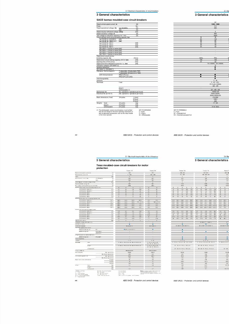
SACE Isomax moulded-case circuit-breakers
KEY TO VERSIONSF = FixedP = Plug-inW = Withdrawable
8/3/2019 ABB Electrical Install Ti On Handbook 4th Edition
http://slidepdf.com/reader/full/abb-electrical-install-ti-on-handbook-4th-edition 25/322
8/3/2019 ABB Electrical Install Ti On Handbook 4th Edition
http://slidepdf.com/reader/full/abb-electrical-install-ti-on-handbook-4th-edition 26/322
46 ABB SACE - Protection and control devices
3 General characteristics
3.1 Electrical characteristics of circuit-breakers
KEY TO VERSIONSF = FixedP = Plug- inW= Withdrawable
KEY TO TERMINALSF = FrontEF = Extended frontES = Extended spreaded
front
FC CuAl = Front for copperor aluminium cablesR = Rear threaded
Rated uninterrupted, IuRated current, In
PolesRated operational voltage (ac) 50-60 Hz, UeRated impulse withstand voltage, UimpRated insulation voltage, UiTest voltage at industrial frequency for 1 minuteRated ultimate short-circuit braking capacity, Icu
[A][A]
No[V][kV]
[V][V]
(ac) 50-60Hz 220/230V
(ac) 50-60Hz 380/415V
(ac) 50-60Hz 440V
(ac) 50-60Hz 500V
(ac) 50-60Hz 690V
[kA][kA][kA]
[kA][kA]
Rated service short-circuit braking capacity, IcsRated short-circuit making capacity (415Vac), Icm
Opening time (415Vac at Icu)Utilization category (EN 60947-2)Iinsulation behaviourReference standardIEC 60947-2, EN60947-2IEC 60947-4-1, EN60947-4-1Microprocessor-based releaseInterchangeabilityVersions
[%Icu][kA]
[ms]
FixedPlug-inWithdrawable
Terminals
[No. of operations][Operations per hour]
L [mm]D [mm]H [mm]3 poles fixed [kg]3 poles plug-in [kg]3 poles withdrawable [kg]
Mechanical life
Basic dimensions, fixed 3 poles
Weight
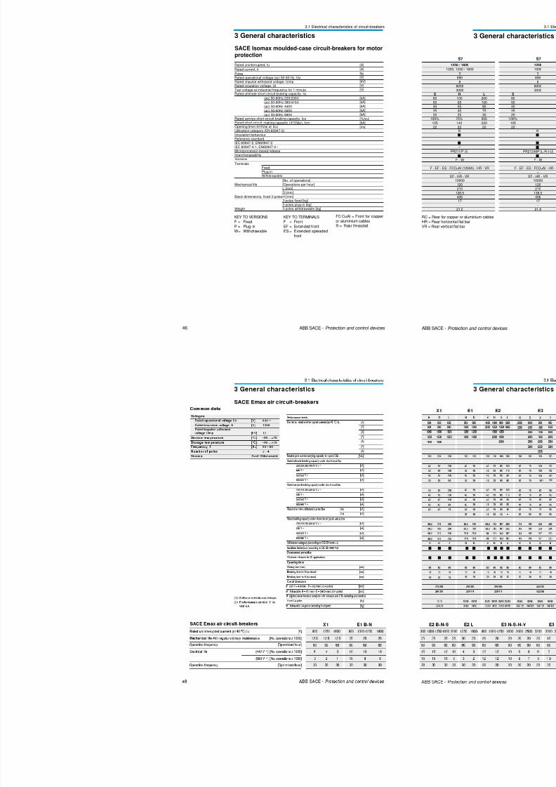
SACE Isomax moulded-case circuit-breakers for motorprotection
8/3/2019 ABB Electrical Install Ti On Handbook 4th Edition
http://slidepdf.com/reader/full/abb-electrical-install-ti-on-handbook-4th-edition 27/322
8/3/2019 ABB Electrical Install Ti On Handbook 4th Edition
http://slidepdf.com/reader/full/abb-electrical-install-ti-on-handbook-4th-edition 28/322
8/3/2019 ABB Electrical Install Ti On Handbook 4th Edition
http://slidepdf.com/reader/full/abb-electrical-install-ti-on-handbook-4th-edition 29/322
52 ABB SACE - Protection and control devices
3 General characteristics
T1 160TMD
In = 16÷63 A
Trip curvethermomagneticrelease
x I1
t [s]
1 10
10-1
10-2
1
10
102
103
104
102
In = 16 A ⇒ I3 = 500 A
In = 20 A ⇒ I3 = 500 A
In = 25 A ⇒ I3 = 500 A
In = 32 A ⇒ I3 = 500 AIn = 40 A ⇒ I3 = 500 A
In = 50÷63 A ⇒ I3 = 10 x In
8/3/2019 ABB Electrical Install Ti On Handbook 4th Edition
http://slidepdf.com/reader/full/abb-electrical-install-ti-on-handbook-4th-edition 30/322
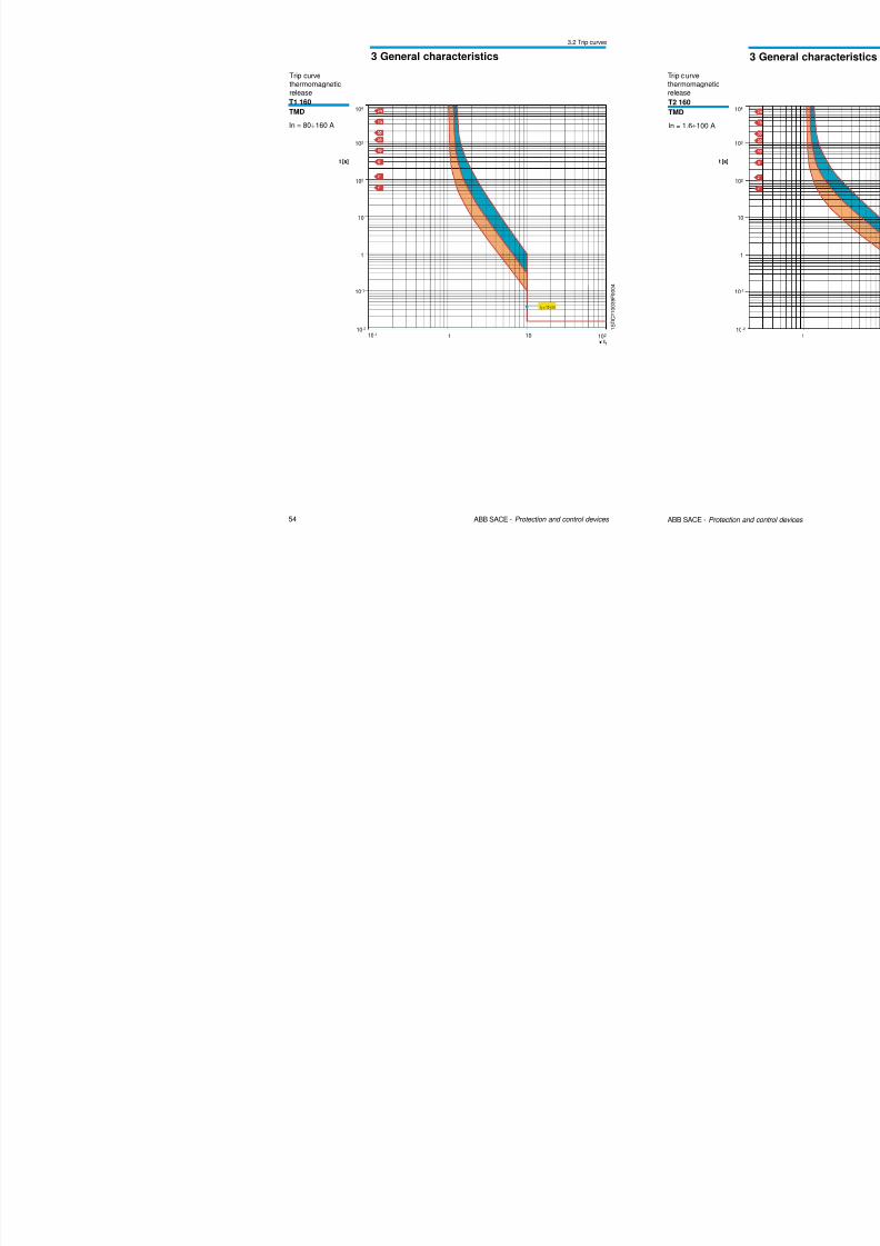
54 ABB SACE - Protection and control devices
3 General characteristics
3.2 Trip curves
Trip curvethermomagneticrelease
t [s]
1x I1
10
10-1
10-2
102
1
10
102
103
104
10-1
I3 = 10 x In
T1 160TMD
In = 80÷160 A
1 S D C 2 1 0 0 3 9
F 0 0 0 4
3 2 T i
8/3/2019 ABB Electrical Install Ti On Handbook 4th Edition
http://slidepdf.com/reader/full/abb-electrical-install-ti-on-handbook-4th-edition 31/322
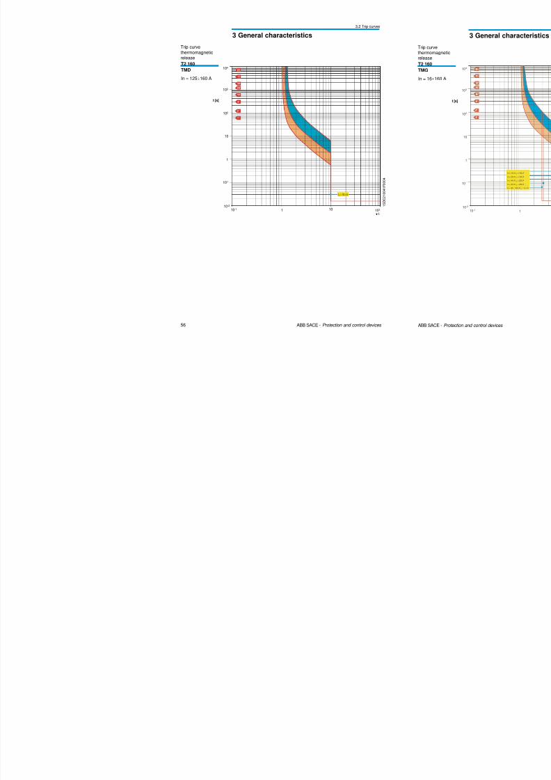
56 ABB SACE - Protection and control devices
3 General characteristics
3.2 Trip curves
1 S D C 2 1 0 0 4 1 F 0 0 0 4
T2 160TMD
In = 125÷160 A
t [s]
1 10
10-1
10-2
102
1
10
102
103
104
10-1
x I1
I3 = 10 x In
Trip curve
thermomagneticrelease
3 2 Trip curves
8/3/2019 ABB Electrical Install Ti On Handbook 4th Edition
http://slidepdf.com/reader/full/abb-electrical-install-ti-on-handbook-4th-edition 32/322
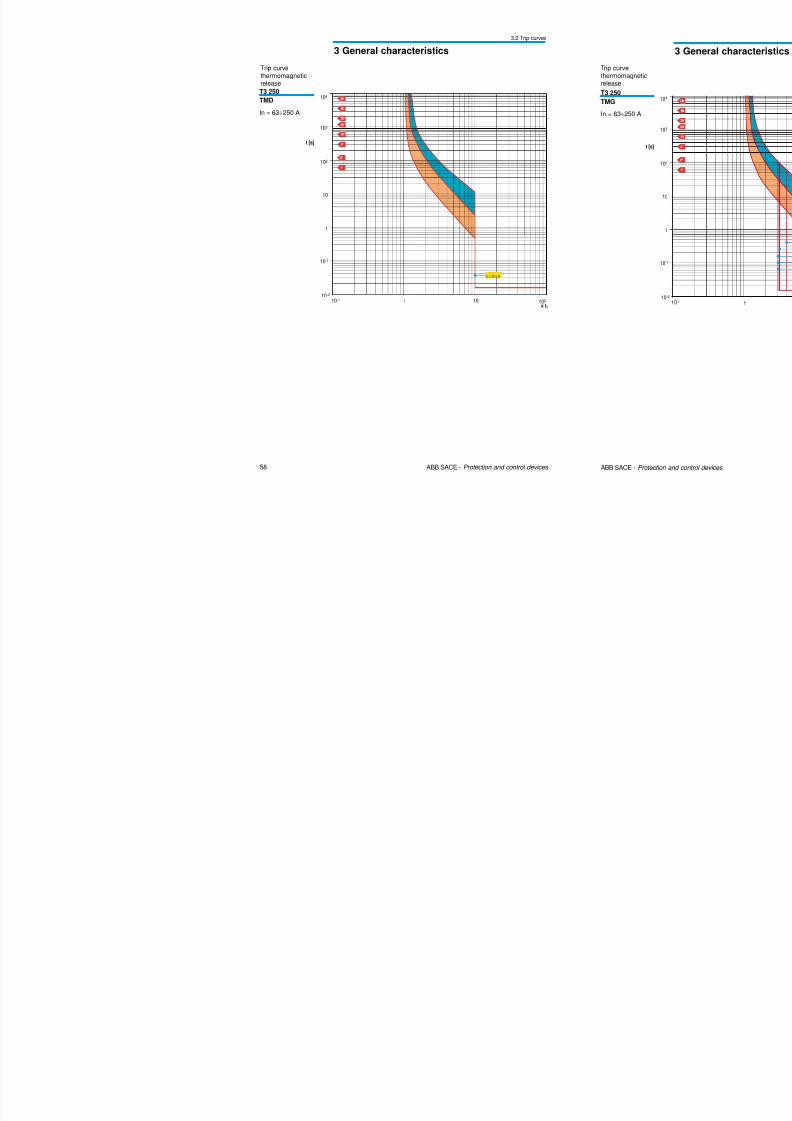
58 ABB SACE - Protection and control devices
3 General characteristics
3.2 Trip curves
Trip curvethermomagneticrelease
T3 250TMD
In = 63÷250 A
x I1
t [s]
1 10
10-1
10-2
102
1
10
102
103
104
10-1
I3 = 10 x In
3 2 Trip curves
8/3/2019 ABB Electrical Install Ti On Handbook 4th Edition
http://slidepdf.com/reader/full/abb-electrical-install-ti-on-handbook-4th-edition 33/322
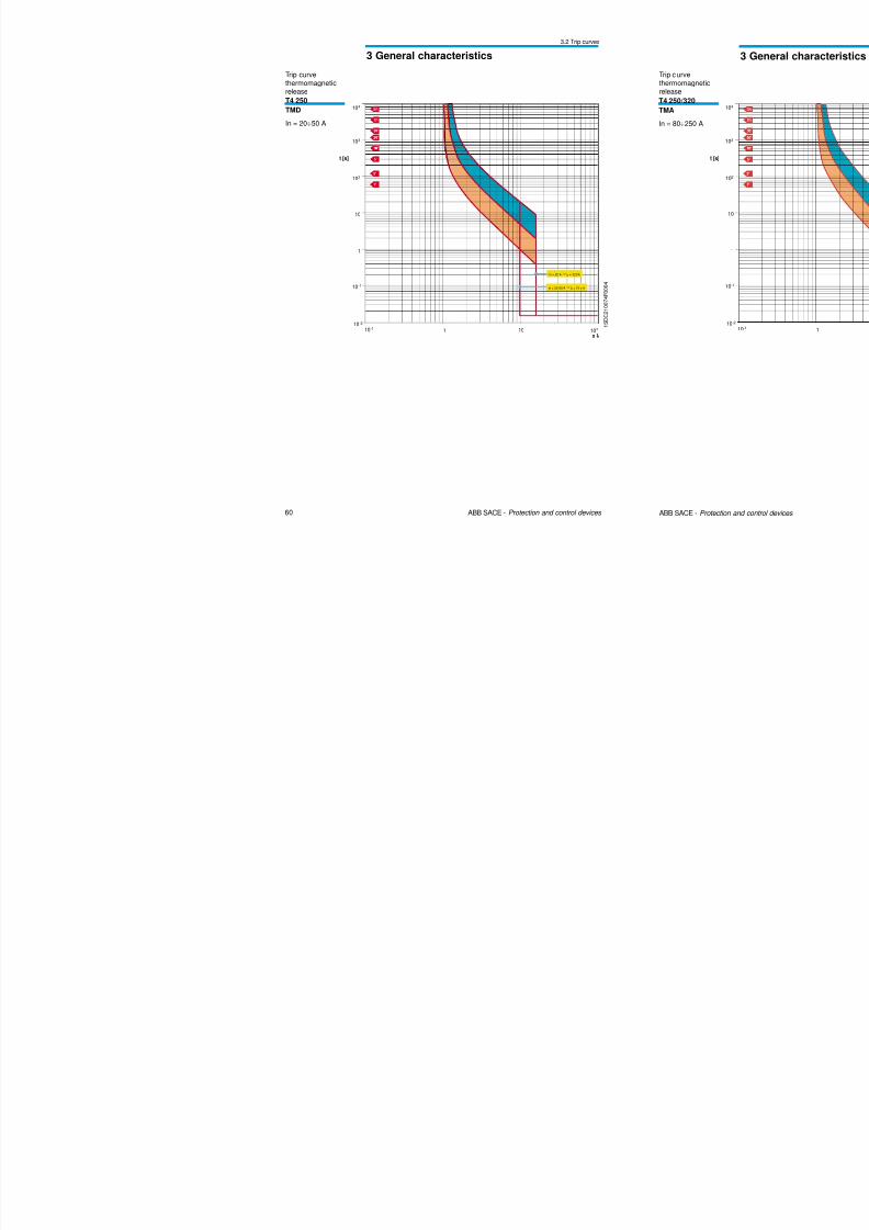
60 ABB SACE - Protection and control devices
3 General characteristics
3.2 Trip curves
1 S D C 2 1 0 0 7 4
F 0 0 0 4
1 10
10-1
10-2
102
1
10
102
103
104
10-1
x I1
In = 20 A ⇒ I3 = 320A
In = 32-50 A ⇒ I3 = 10 x In
t [s]
T4 250TMD
In = 20÷50 A
Trip curvethermomagneticrelease
3.2 Trip curves
8/3/2019 ABB Electrical Install Ti On Handbook 4th Edition
http://slidepdf.com/reader/full/abb-electrical-install-ti-on-handbook-4th-edition 34/322
62 ABB SACE - Protection and control devices
3 General characteristics
p
Trip curvethermomagneticrelease
1 S D C 2 1 0 0 3 4 F 0 0 0 4
T5 400/630TMA
In = 320÷500 A
1 10
10-1
10-2
102
1
10
102
103
104
10-1
x I1
I3 = 5…
10 x In
t [s]
3.2 Trip curves

8/3/2019 ABB Electrical Install Ti On Handbook 4th Edition
http://slidepdf.com/reader/full/abb-electrical-install-ti-on-handbook-4th-edition 35/322
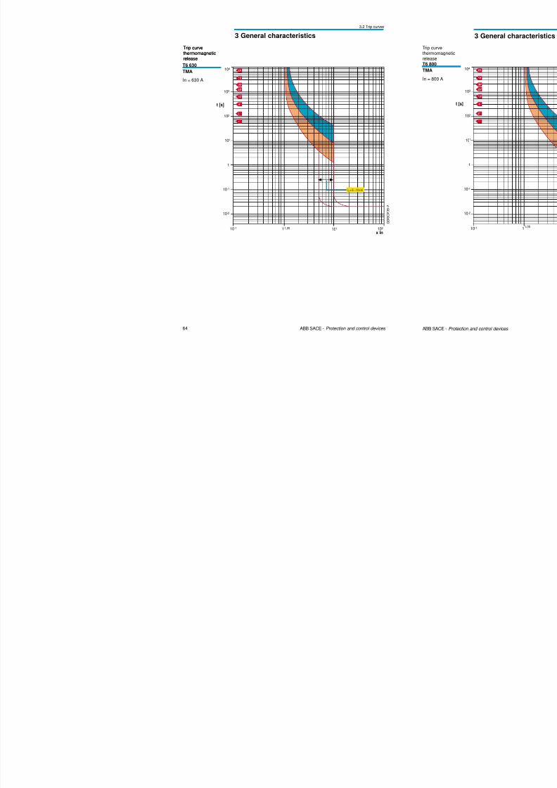
64 ABB SACE - Protection and control devices
3 General characteristics
Trip curvethermomagneticrelease
G S I S O 2 0 9 - 2
103
t [s]
10-1
x In1
1
102
10-1
10-2
1,05 102
104
101
101
I3 = 5…
10 x In
Trip curvethermomagneticrelease
T6 630TMA
In = 630 A
3.2 Trip curves
8/3/2019 ABB Electrical Install Ti On Handbook 4th Edition
http://slidepdf.com/reader/full/abb-electrical-install-ti-on-handbook-4th-edition 36/322
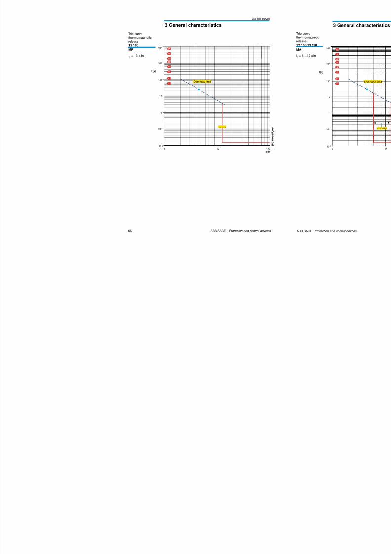
66 ABB SACE - Protection and control devices
3 General characteristics
T2 160
MF
I3
= 13 x In
t [s]
1x In
10
10-1
10-2
102
1
10
102
103
104
I3 = 13 x In
Overload limit
1 S D C 2 1 0 0 4 5
F 0 0 0 4
1 S D C 2 1 0 0 4 5
F 0 0 0 4
Trip curvethermomagneticrelease
3.2 Trip curves
8/3/2019 ABB Electrical Install Ti On Handbook 4th Edition
http://slidepdf.com/reader/full/abb-electrical-install-ti-on-handbook-4th-edition 37/322
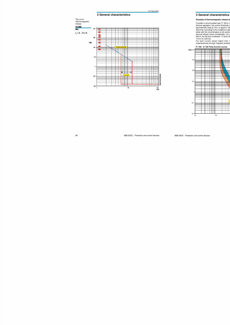
68 ABB SACE - Protection and control devices
3 General characteristics
1 S D C 2 1 0 0 7 6 F 0 0 0 4
T4 250MA
I3
= 6…14 x In
t [s]
1x In
10
10-1
10-2
102
1
10
102
103
104
I3 = 6…
14 x In
Overload limit
1 S D C 2 1 0 0 7 6 F 0 0 0 4
T4 250MA
I3
= 6…14 x In
t [s]
1x In
10
10-1
10-2
102
1
10
102
103
104
I3 = 6…
14 x In
Overload limit
Trip curvethermomagnetic
release
3.2 Trip curves
8/3/2019 ABB Electrical Install Ti On Handbook 4th Edition
http://slidepdf.com/reader/full/abb-electrical-install-ti-on-handbook-4th-edition 38/322
70 ABB SACE - Protection and control devices
3 General characteristics
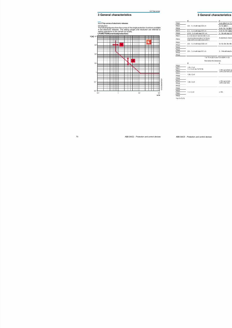
I1
t1
x In
t [s]
103
1
102
10-1
104
101
10-2
1 101 10210-1
1 S D C 0 0 8 0 0 6 F 0 0 0 1
L FUNCTION (overload protection)
3.2.2 Trip curves of electronic releases
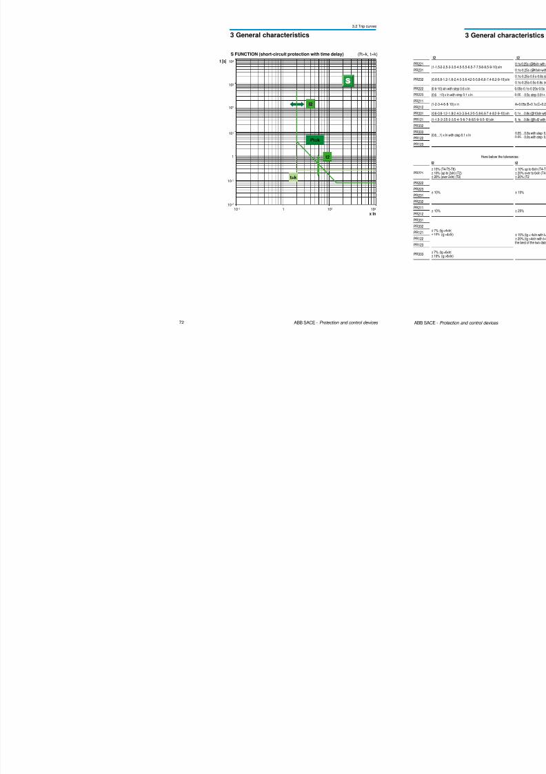
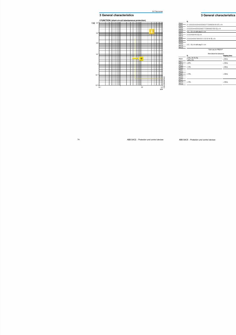
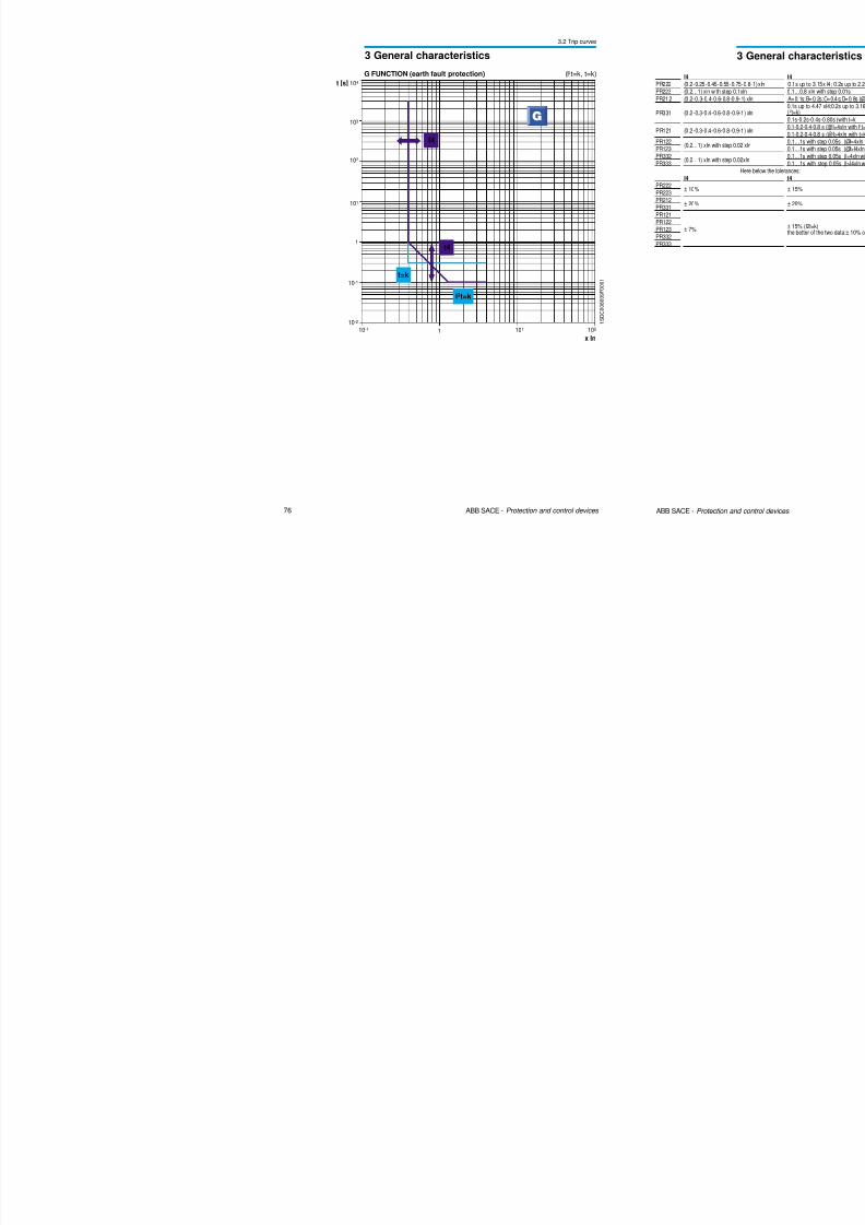
Introduction
The following figures show the curves of the single protection functions availablein the electronic releases. The setting ranges and resolution are referred tosetting operations to be carried out locally.
G l h i i
3.2 Trip curves
8/3/2019 ABB Electrical Install Ti On Handbook 4th Edition
http://slidepdf.com/reader/full/abb-electrical-install-ti-on-handbook-4th-edition 39/322
72 ABB SACE - Protection and control devices
3 General characteristics
I2
I2t=k
t2
t=k
1
x In
t [s]
101
103
1
102
10-1
104
101
10-2
10210-1
S FUNCTION (short-circuit protection with time delay) (I2t=k, t=k)
3 G l h t i ti
3.2 Trip curves
8/3/2019 ABB Electrical Install Ti On Handbook 4th Edition
http://slidepdf.com/reader/full/abb-electrical-install-ti-on-handbook-4th-edition 40/322
74 ABB SACE - Protection and control devices
3 General characteristics
I3
1
x In
t [s]
101
103
1
102
10-1
104
101
10-2
10210-1 1 S D C 0 0 8 0 0 8 F 0 0 0 1
I FUNCTION (short-circuit istantaneous protection)
3 General characteristics
3.2 Trip curves
8/3/2019 ABB Electrical Install Ti On Handbook 4th Edition
http://slidepdf.com/reader/full/abb-electrical-install-ti-on-handbook-4th-edition 41/322
76 ABB SACE - Protection and control devices
3 General characteristics
1 S D C 0 0 8 0 0 9 F 0 0 0 1
101
103
1
102
10-1
104
101
10-2
10210-1 1
x In
t [s]
t4
I2t=k
t=k
I4
G FUNCTION (earth fault protection) (I2t=k, t=k)
3 General characteristics
3.2 Trip curves
8/3/2019 ABB Electrical Install Ti On Handbook 4th Edition
http://slidepdf.com/reader/full/abb-electrical-install-ti-on-handbook-4th-edition 42/322
78 ABB SACE - Protection and control devices
3 General characteristics
t [s]
1I [kA]
10 -1
10 -2
1
102
103
104
10 -1
10 -3
10 -1 1 10
87 7,5 96,5 8,5 10
A
BA
B
0,4-0,44-0,48-0,52-0,56-0,60-0,64-0,68-0,72-0,76-0,80-0,84-0,88-0,92-0,96-1
0,4 1
102
x In
101
101
Up to In = 10 A
4,55,5
3,53
2,5
2
1,5
1
T S T M 0 0 0 5
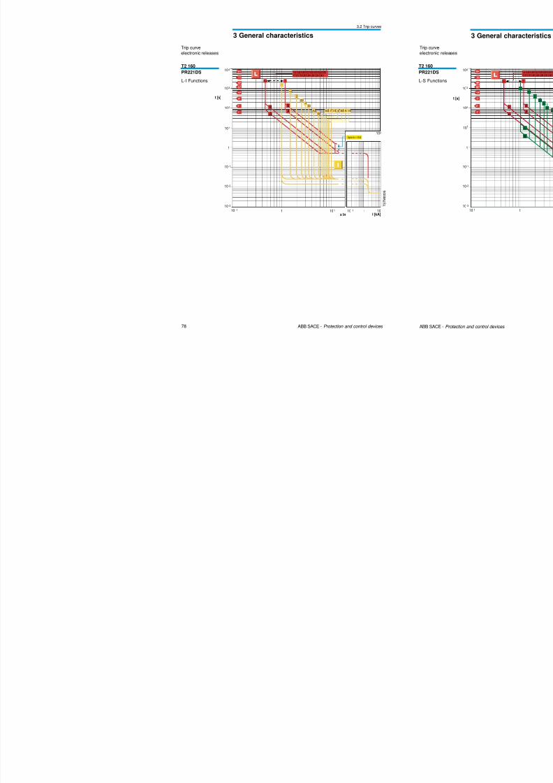
T2 160PR221DS
L-I Functions
Trip curveelectronic releases
3 General characteristics
3.2 Trip curves

8/3/2019 ABB Electrical Install Ti On Handbook 4th Edition
http://slidepdf.com/reader/full/abb-electrical-install-ti-on-handbook-4th-edition 43/322
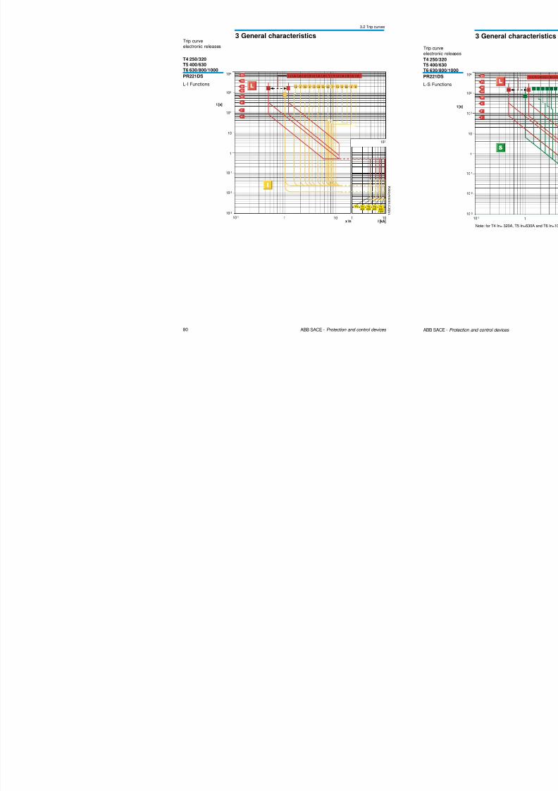
80 ABB SACE - Protection and control devices
3 General characteristics
t [s]
1 10
10-1
10-2
1
10
102
103
104
10-1
10-3
x In
0,4-0,44-0,48-0,52-0,56-0,6-0,64-0,68-0,72-0,76-0,8-0,84-0,88-0,92-0,96-1
102
0,4 11,5 2 2,5 3 3,5 4 ,5 5 ,5 6 ,5 7 7, 5 8 8,5 9 10
1
I [kA]101
T6800
1000
T6630
T5630
T5400
T4
Trip curveelectronic releases
T4 250/320T5 400/630
T6 630/800/1000
PR221DS
L-I Functions
1 S D C 2 1 0 0 0 5 F 0 0 0 4
3 General characteristics
3.2 Trip curves

8/3/2019 ABB Electrical Install Ti On Handbook 4th Edition
http://slidepdf.com/reader/full/abb-electrical-install-ti-on-handbook-4th-edition 44/322
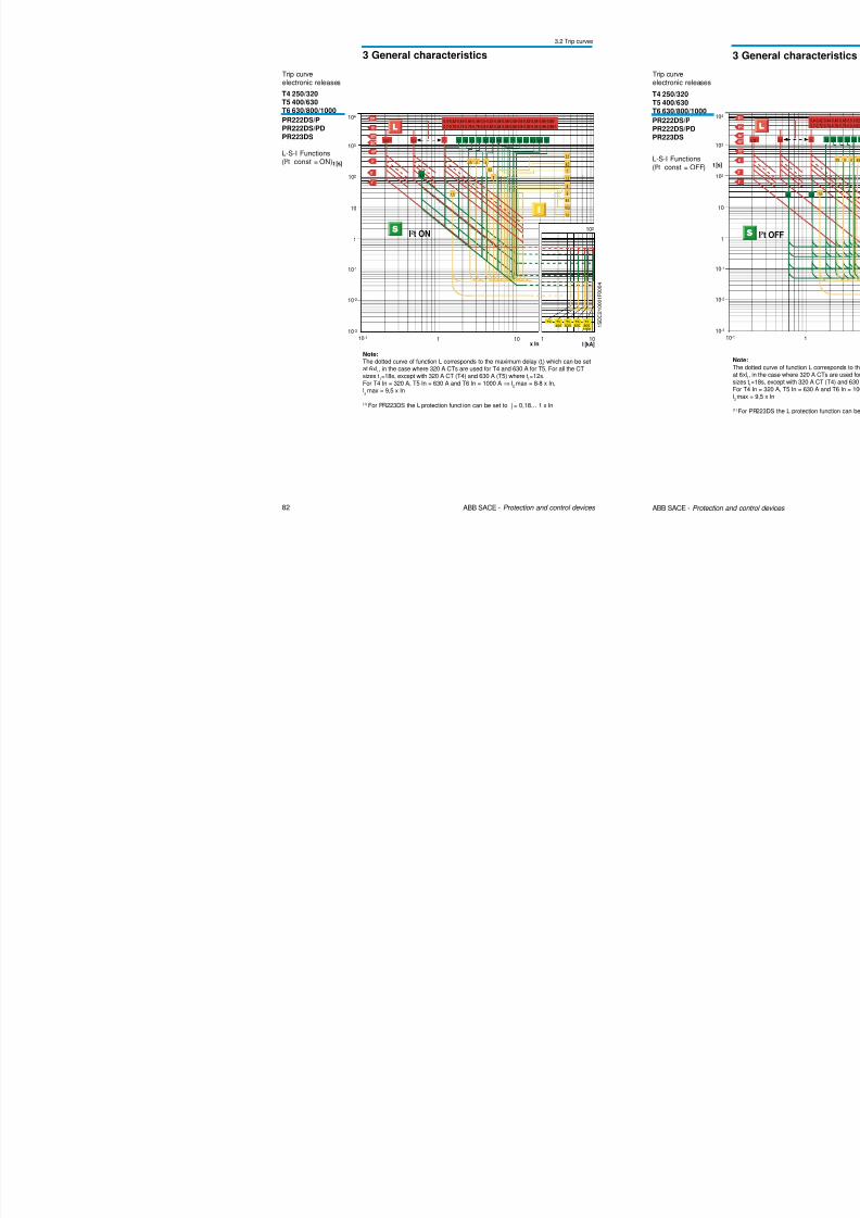
82 ABB SACE - Protection and control devices
3 General characteristics
Trip curveelectronic releases
T4 250/320
T5 400/630T6 630/800/1000
PR222DS/PPR222DS/PD
PR223DS
L-S-I Functions(I2t const = ON) t [s]
1 10
10-1
10-2
1
10
102
103
104
10-1
10-3
x In
I2t ON
0,4-0,42-0,44-0,46-0,48-0,5-0,52-0,54-0,56-0,58-0,6-0,62-0,64-0,66-0,68-
0,7-0,72-0,74-0,76-0,78-0,8-0,82-0,84-0,86-0,88-0,9-0,92-0,94-0,96-0,98-1
I [kA]101
T68001000
T6630
T5630
T5400
T4
0,4 1 1 ,2 1 ,8 2 ,4 3 3 ,6 4 ,2 5 ,8 6 ,4 7 7 ,6 8 ,2 8 ,8 9,4 10
0,6
5,5
6,5
7
7,5
8
9
9,510,5
12
1,5
2 ,5 3 4
4,5
5
102
0,18 (1)
1 S D C 2 1 0 0 0 1
F 0 0 0 4
Note:
The dotted curve of function L corresponds to the maximum delay (t1) which can be set
at 6xl1, in the case where 320 A CTs are used for T4 and 630 A for T5. For all the CT
sizes t1=18s, except with 320 A CT (T4) and 630 A (T5) where t
1=12s.
For T4 In = 320 A, T5 In = 630 A and T6 In = 1000 A ⇒ I2max = 8.8 x In,
I3max = 9,5 x In
(1) For PR223DS the L protection funct ion can be set to I1= 0,18… 1 x In
3 General characteristics
3.2 Trip curves
8/3/2019 ABB Electrical Install Ti On Handbook 4th Edition
http://slidepdf.com/reader/full/abb-electrical-install-ti-on-handbook-4th-edition 45/322
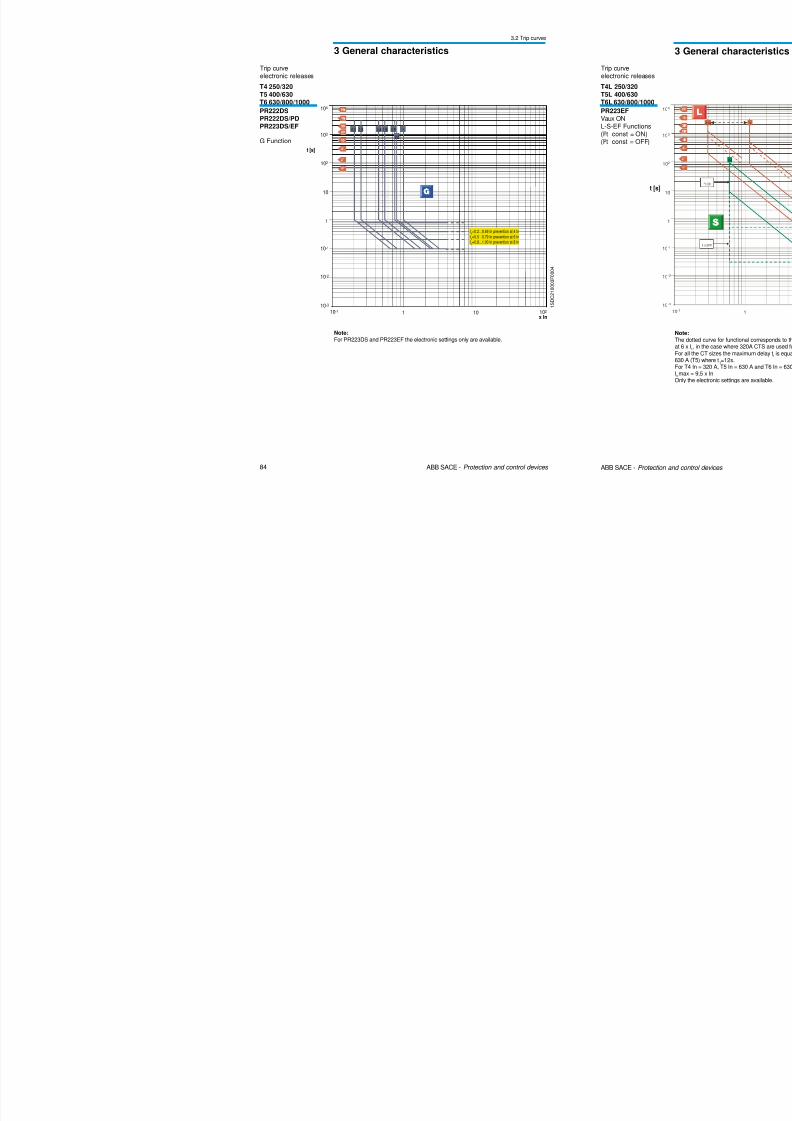
84 ABB SACE - Protection and control devices
Trip curveelectronic releases
T4 250/320
T5 400/630T6 630/800/1000
PR222DSPR222DS/PDPR223DS/EF
G Function
t [s]
1 10
10-1
10-2
1
10
102
103
104
10-1
10-3
102
x In
0,2 0, 25 0, 45 0, 55 0, 75 1
0,8
I4=0.2…0.49 In prevention at 4 In
I4=0.5…0.79 In prevention at 6 In
I4=0.8…1.00 In prevention at 8 In
1 S D C 2 1 0 0 0 3 F 0 0 0 4
Note:
For PR223DS and PR223EF the electronic settings only are available.
3 General characteristics
3.2 Trip curves
8/3/2019 ABB Electrical Install Ti On Handbook 4th Edition
http://slidepdf.com/reader/full/abb-electrical-install-ti-on-handbook-4th-edition 46/322
86 ABB SACE - Protection and control devices
Trip curveelectronic releases
T4L 250/320
T5L 400/630T6L 630/800/1000
PR223EFVaux OFFL-S-EF Functions(I2t const = ON)(I2t const = OFF)
t [s]
1I [kA]
10
10-1
10-2
1
10
102
103
104
10-1
10-3
102
x In
102
1
T6 630
T5 630
T5 400
T4
T6 800T6 1000
10
0.18 1
0.6
I
2
t ON
I2t OFF
Note:
For all the CT sizes the maximum delay t1
is equal to 18s, except for 320 A CT (T4) and630 A (T5) where t
1=12s.
For T4 In = 320 A, T5 In = 630 A and T6 In = 630 A ⇒ I3max = 10 x In.
Only the electronic settings are available.
3 General characteristics
3.2 Trip curves
8/3/2019 ABB Electrical Install Ti On Handbook 4th Edition
http://slidepdf.com/reader/full/abb-electrical-install-ti-on-handbook-4th-edition 47/322
88 ABB SACE - Protection and control devices
t [s]
1I [kA]
10
10-1
10-2
1
10
102
103
104
10-1
10-3
102
x In
10
10
0,4 1
1
0,4...1
1...10
t = k / I2
T7 V
T7 S,H,L
102
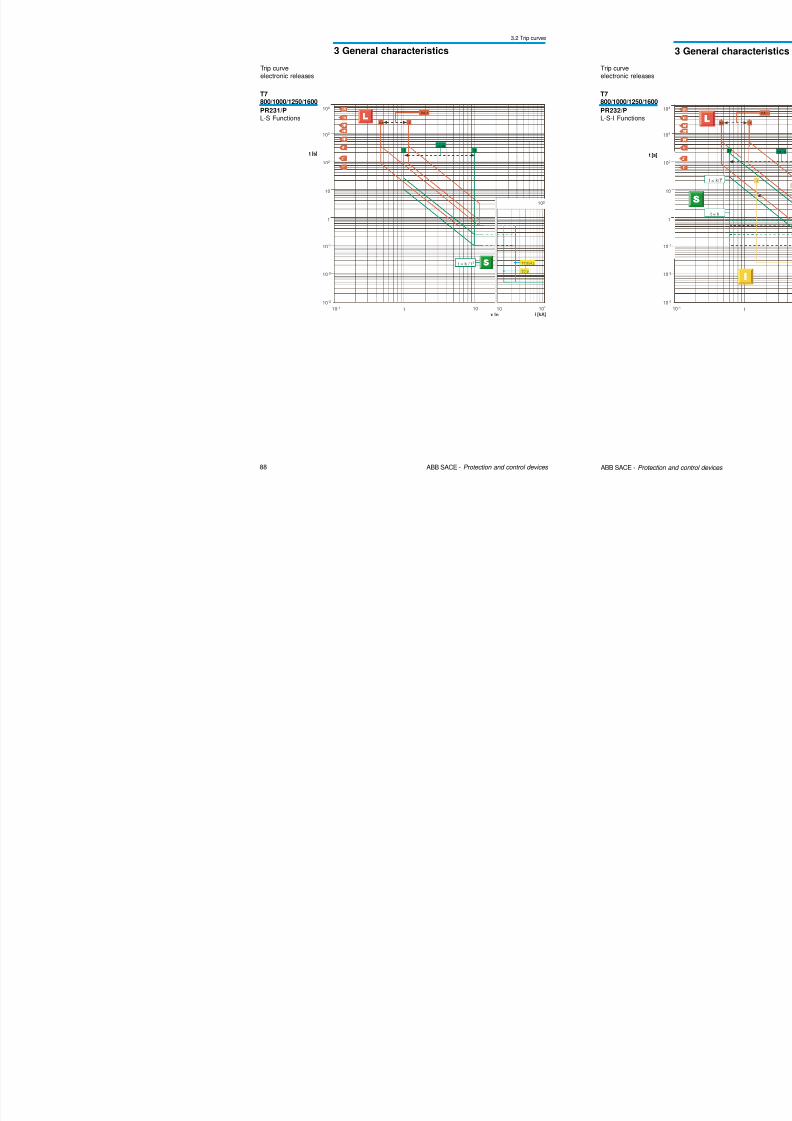
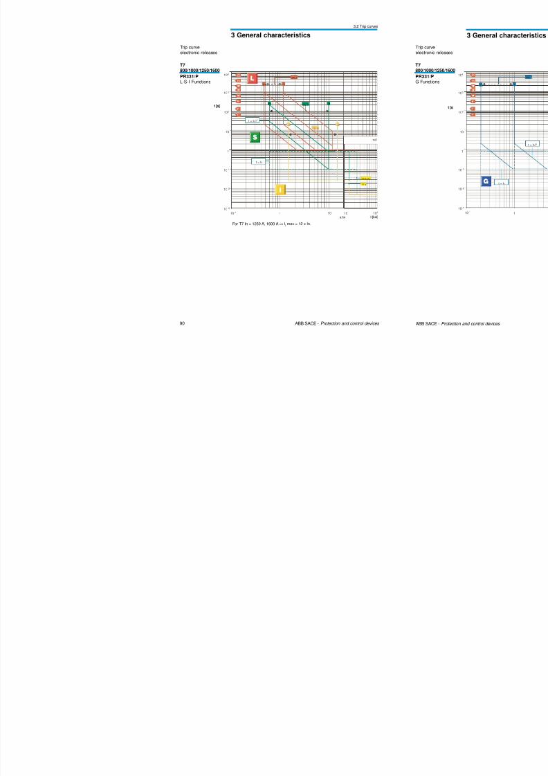
Trip curveelectronic releases
T7800/1000/1250/1600
PR231/PL-S Functions
3 General characteristics
3.2 Trip curves
8/3/2019 ABB Electrical Install Ti On Handbook 4th Edition
http://slidepdf.com/reader/full/abb-electrical-install-ti-on-handbook-4th-edition 48/322
90 ABB SACE - Protection and control devices
t [s]
1I [kA]
10
10-1
10-2
1
10
102
103
104
10-1
10-3
102
x In
102
10
10
0.4 1
0,6
0.4...1
0.6...10
t = k
1.5 15
t = k/I2
1.5...15
T7 V
T7 S,H,L
Trip curveelectronic releases
T7800/1000/1250/1600
PR331/PL-S-I Functions
For T7 In = 1250 A, 1600 A ⇒ I3max = 12 x In.
3 General characteristics
3.2 Trip curves
8/3/2019 ABB Electrical Install Ti On Handbook 4th Edition
http://slidepdf.com/reader/full/abb-electrical-install-ti-on-handbook-4th-edition 49/322
92 ABB SACE - Protection and control devices
t [s]
1I [kA]
10
10-1
10-2
1
10
102
103
104
10-1
10-3
102
x In
102
10
0,4 1
1.515
0,4...1
1.5...15
T7 V
T7 S,H,L
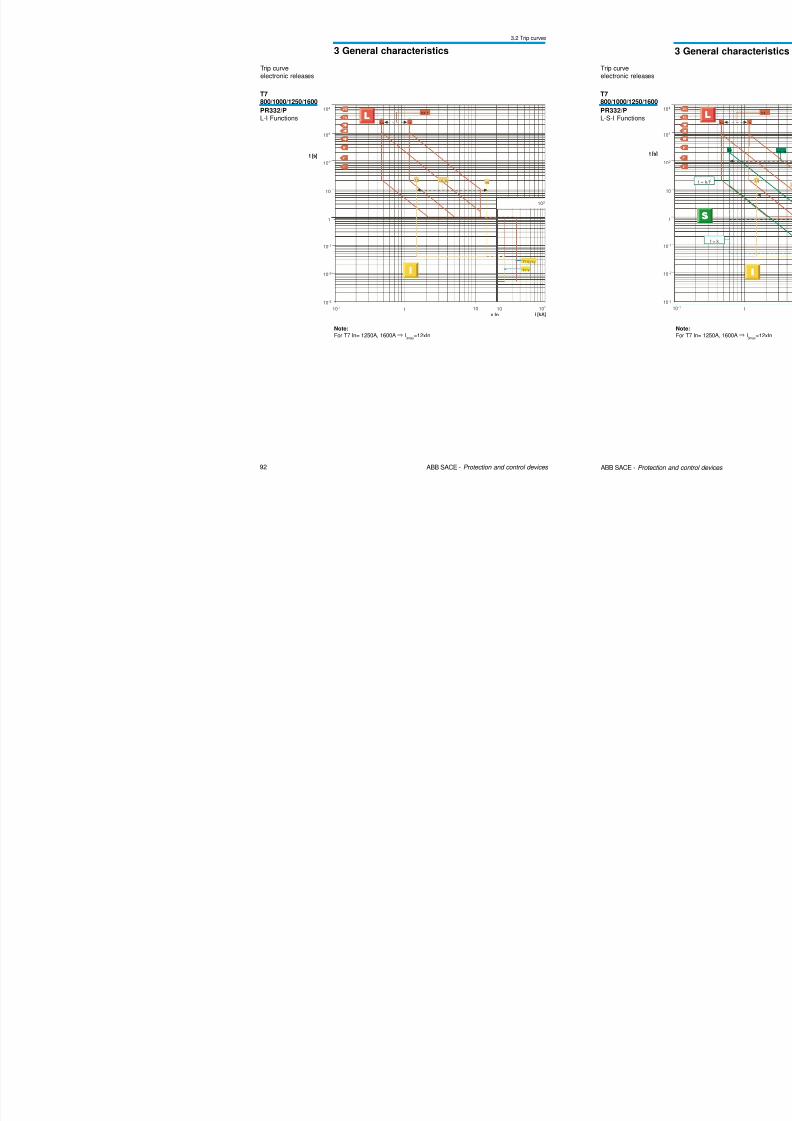
T7800/1000/1250/1600
PR332/PL-I Functions
Trip curveelectronic releases
Note:
For T7 In= 1250A, 1600A⇐I3max
=12xIn
3 General characteristics
3.2 Trip curves
8/3/2019 ABB Electrical Install Ti On Handbook 4th Edition
http://slidepdf.com/reader/full/abb-electrical-install-ti-on-handbook-4th-edition 50/322
94 ABB SACE - Protection and control devices
t [s]
1I [kA]
10
10-1
10-2
1
10
102
103
104
10-1
10-3
0,2...1
0,2 1
t = k/I2
t = k
10 2
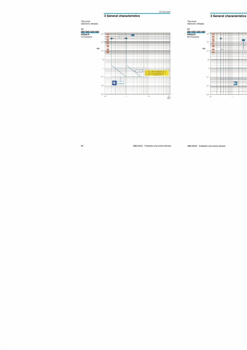
I4 = 0.2..0.48 In disabled at 4 InI4 = 0.5..0.78 In disabled at 6 InI4 = 0.8..1 In disabled at 8 In
T7800/1000/1250/1600
PR332/PG Functions
Trip curveelectronic releases
3 General characteristics
3.2 Trip curves
8/3/2019 ABB Electrical Install Ti On Handbook 4th Edition
http://slidepdf.com/reader/full/abb-electrical-install-ti-on-handbook-4th-edition 51/322
96 ABB SACE - Protection and control devices
Trip curve
electronic releases
t [s]
1I [kA]
10
10-1
10-2
1
10
102
103
104
10-1
10-3
10-1 1 10
7 7 ,5 8 8,5 9 102,51,5 2 3,51 3 4,5 5,5 6,5
102
x In
Overload limit
1 S D C 2 1 0 0 4 7 F 0
0 0 4
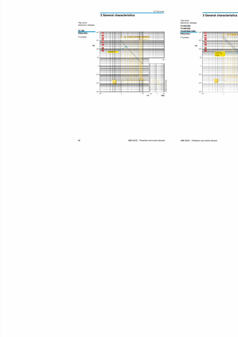
T2 160
PR221DS-I
I Function
3 General characteristics
3.2 Trip curves
8/3/2019 ABB Electrical Install Ti On Handbook 4th Edition
http://slidepdf.com/reader/full/abb-electrical-install-ti-on-handbook-4th-edition 52/322
98 ABB SACE - Protection and control devices
1I [kA]
10
10-1
10-2
1
10
102
103
104
10-1
10-3
102
x In
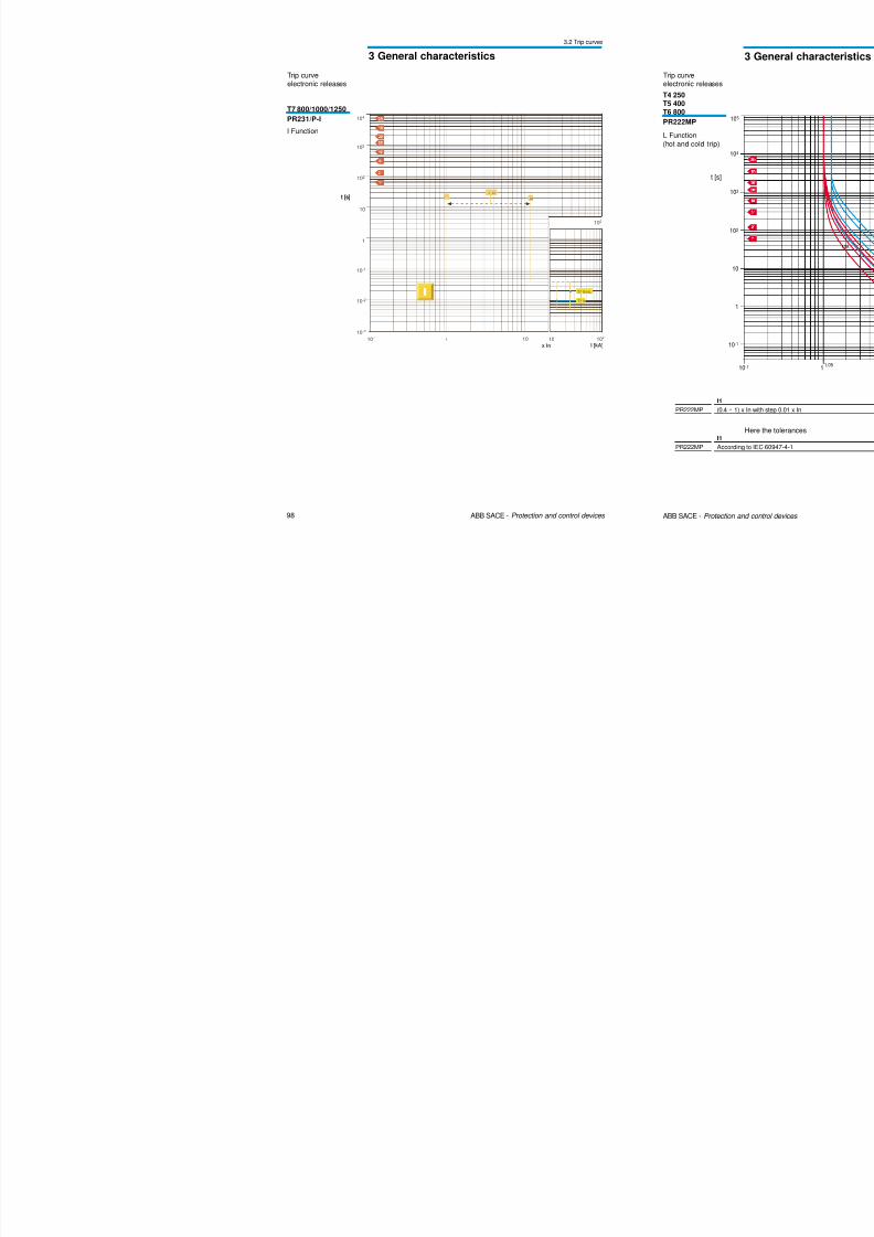
102
10
112
1...12
T7 V
T7 S,H,L
t [s]
Trip curveelectronic releases
T7 800/1000/1250PR231/P-I
I Function
3 General characteristics
3.2 Trip curves
8/3/2019 ABB Electrical Install Ti On Handbook 4th Edition
http://slidepdf.com/reader/full/abb-electrical-install-ti-on-handbook-4th-edition 53/322
100 ABB SACE - Protection and control devices
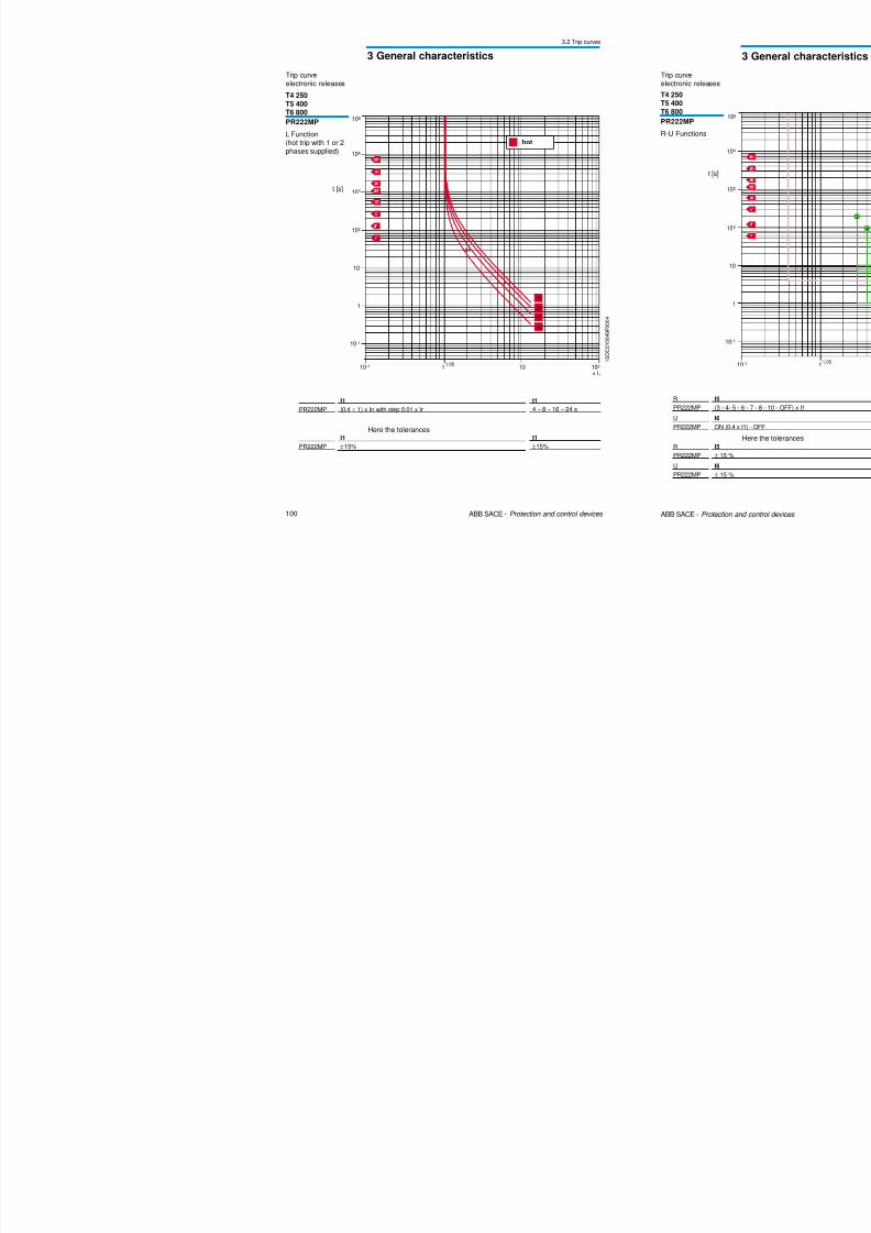
Trip curveelectronic releases
T4 250
T5 400T6 800
PR222MP
L Function(hot trip with 1 or 2phases supplied)
1 S D C 2 1 0 0 4 9 F 0 0 0 4
104
t [s]
10-1
x I1101
102
10
103
1
10-1
1,05102
105
30
20
10
10A
10A
hot
PR222MPI1(0.4 ÷ 1) x In with step 0.01 x In
t14 – 8 – 16 – 24 s
Here the tolerances
PR222MP
I1
±15%
t1
±15%
3 General characteristics
3.2 Trip curves
T i
8/3/2019 ABB Electrical Install Ti On Handbook 4th Edition
http://slidepdf.com/reader/full/abb-electrical-install-ti-on-handbook-4th-edition 54/322
102 ABB SACE - Protection and control devices
Trip curveelectronic releases
T4 250
T5 400
T6 800
PR222MP
I Functions
1I [kA]
10
10-1
10-2
1
10
102
103
10-1
10-3
10
6...13
2
6 13
t [s]
1 S D C 2 1 0 0 5 1 F 0 0 0 4
PR222MPI3(6 - 7- 8 - 9 - 10 - 11 - 12 - 13) x In
Here the tolerances
PR222MP
I3
± 15 %
3 General characteristics
3.2 Trip curves
Trip curve
8/3/2019 ABB Electrical Install Ti On Handbook 4th Edition
http://slidepdf.com/reader/full/abb-electrical-install-ti-on-handbook-4th-edition 55/322
104 ABB SACE - Protection and control devices
103
t [s]
10-1
x In1
1
102
10-1
10-2
1,05102
104
I2t ON
0,4-0,5-0,55-0,6-0,65-0,7-0,75-0,8-0,85-0,875-0,9-0,925-0,95-0,975-1
0,4 1
1,5
2
4
6
12
10
8
A
B
C
D
D
C
B
A
1
D
C
B
A
2
3
4
6
8
10
101
101
G S I S 0 2 1 2
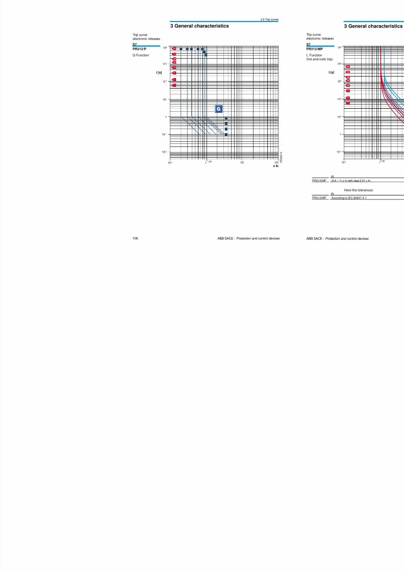
S7
PR212/P
L-S-I Functions,S inverse short
delay(I2t =constant)
Trip curveelectronic releases
3 General characteristics
3.2 Trip curves
Trip curve
8/3/2019 ABB Electrical Install Ti On Handbook 4th Edition
http://slidepdf.com/reader/full/abb-electrical-install-ti-on-handbook-4th-edition 56/322
106 ABB SACE - Protection and control devices
103
t [s]
10-1
x In1
1
102
10-1
10-2
1,05 102
1040,30,2 0,4 0,6 0,8
0,9
1
C
D
A
B
101
101 G S I S 0 2 1 4
S7
PR212/P
G Function
Trip curveelectronic releases
3 General characteristics
3.2 Trip curves
Trip curve
8/3/2019 ABB Electrical Install Ti On Handbook 4th Edition
http://slidepdf.com/reader/full/abb-electrical-install-ti-on-handbook-4th-edition 57/322
108 ABB SACE - Protection and control devices
104
t [s]
10-1 1
102
103
1
10-1
1,05102
105
30
20
10
10 A
101
101
x I1
G S I S 0 2 1 7
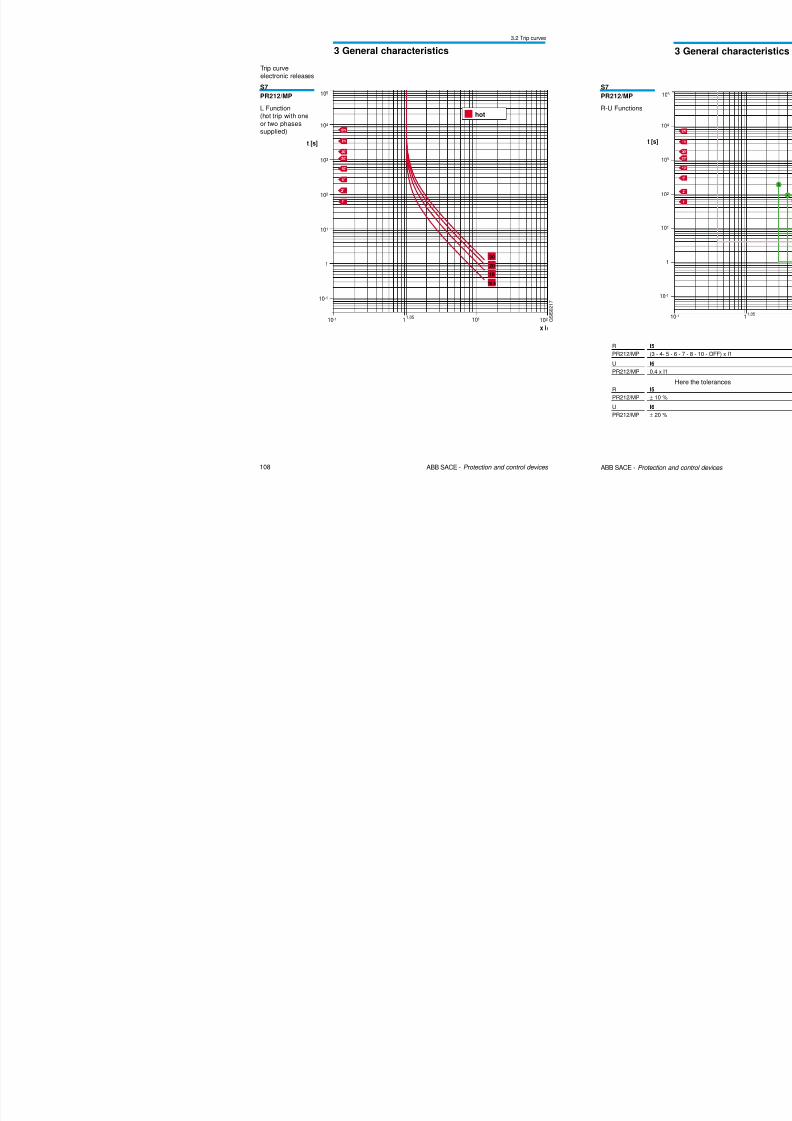
S7
PR212/MP
L Function(hot trip with one
or two phasessupplied)
Trip curveelectronic releases
hot
3 General characteristics
3.2 Trip curves
Trip curve
8/3/2019 ABB Electrical Install Ti On Handbook 4th Edition
http://slidepdf.com/reader/full/abb-electrical-install-ti-on-handbook-4th-edition 58/322
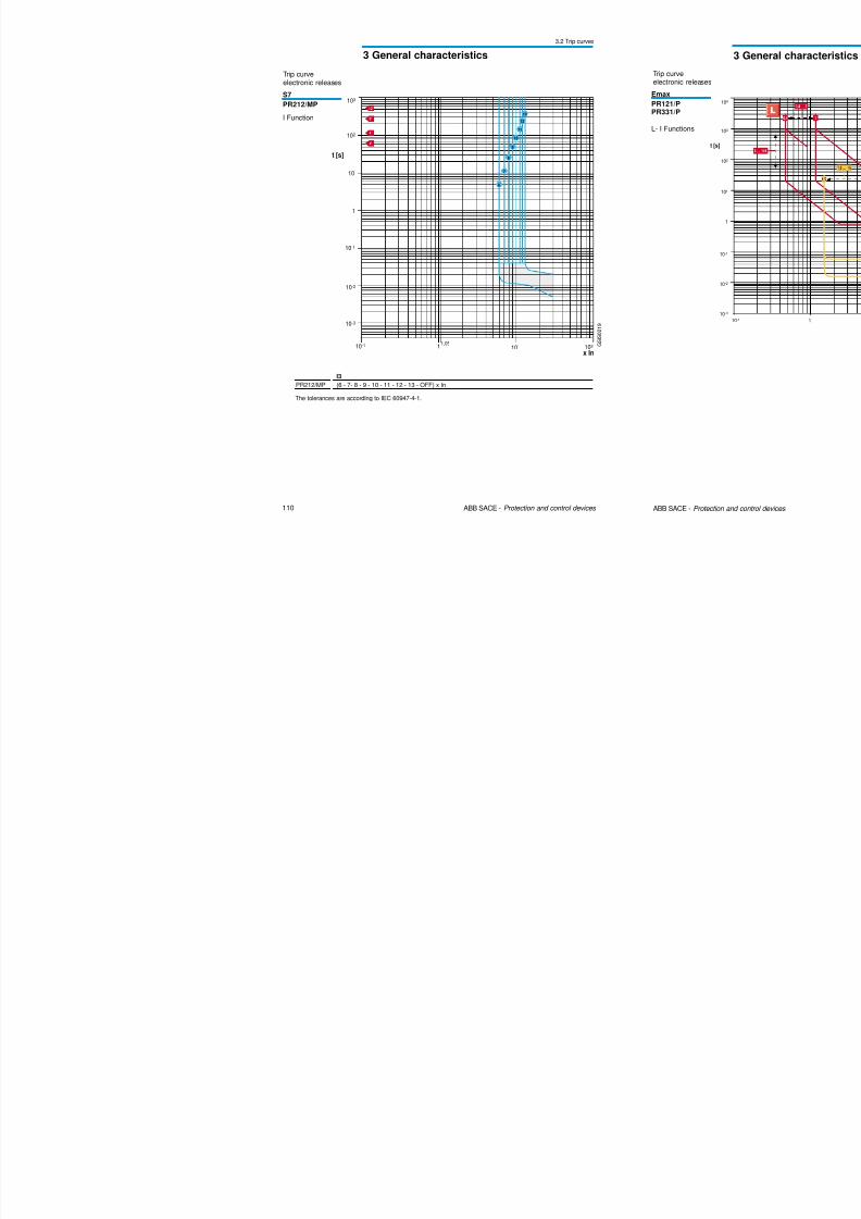
110 ABB SACE - Protection and control devices
G S I S 0 2 1 9
S7
PR212/MP
I Function
pelectronic releases
PR212/MP
I3
(6 - 7- 8 - 9 - 10 - 11 - 12 - 13 - OFF) x In
The tolerances are according to IEC 60947-4-1.
102
t [s]
10-1
x In1
1
10
10-1
1,05102
10-2
10-3
103
13
12
11
10
9
8
7
6
101
3 General characteristics
3.2 Trip curves
Trip curve
8/3/2019 ABB Electrical Install Ti On Handbook 4th Edition
http://slidepdf.com/reader/full/abb-electrical-install-ti-on-handbook-4th-edition 59/322
112 ABB SACE - Protection and control devices
t =k
I2
103
t [s]
1
102
10-1
10-2
104
101
10-3
10-1 1 101 102
x In
1 S D C 2 0 0 1 0 1 F 0 0 0 1
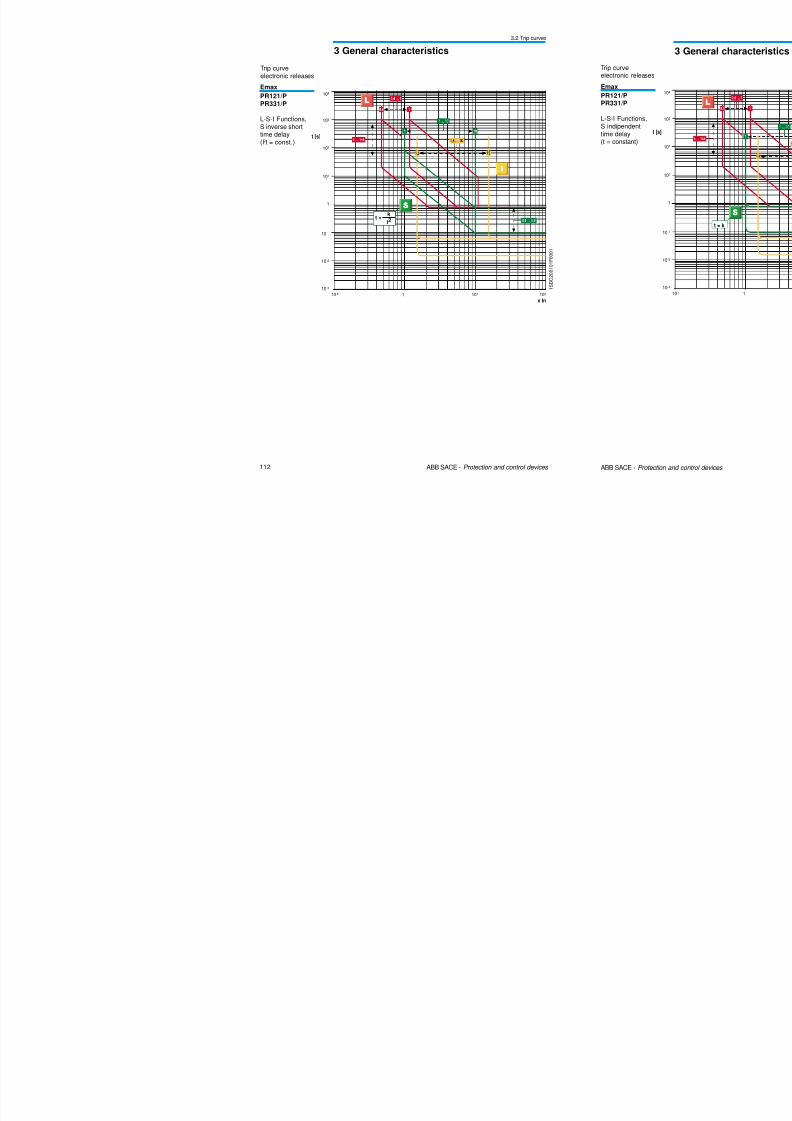
Emax
PR121/PPR331/P
L-S-I Functions,S inverse shorttime delay(I2t = const.)
electronic releases
3 General characteristics
3.2 Trip curves
Trip curvel i l
8/3/2019 ABB Electrical Install Ti On Handbook 4th Edition
http://slidepdf.com/reader/full/abb-electrical-install-ti-on-handbook-4th-edition 60/322
114 ABB SACE - Protection and control devices
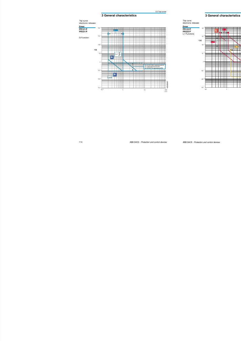
6 G S I S
0 2 6 7
Emax
PR121/PPR331/P
G Function
electronic releases
t [s]
t = k
t =k
I2
I4= 0.2-0.3-0.4In repressionat4 In
I4= 0.6Inrepressionat 6In
I4= 0.8-0.9-1In repressionat 8In
3 General characteristics
3.2 Trip curves
Trip curveelectronic releases
8/3/2019 ABB Electrical Install Ti On Handbook 4th Edition
http://slidepdf.com/reader/full/abb-electrical-install-ti-on-handbook-4th-edition 61/322
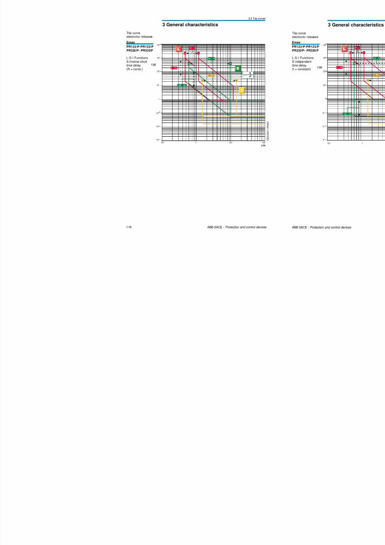
116 ABB SACE - Protection and control devices
t =k
I2
103
t [s]
1
102
10-1
10-2
104
101
10-3
10-1 1 101 102
x In
1 S D C 2 0 0 1 1 0 F 0 0 0 1
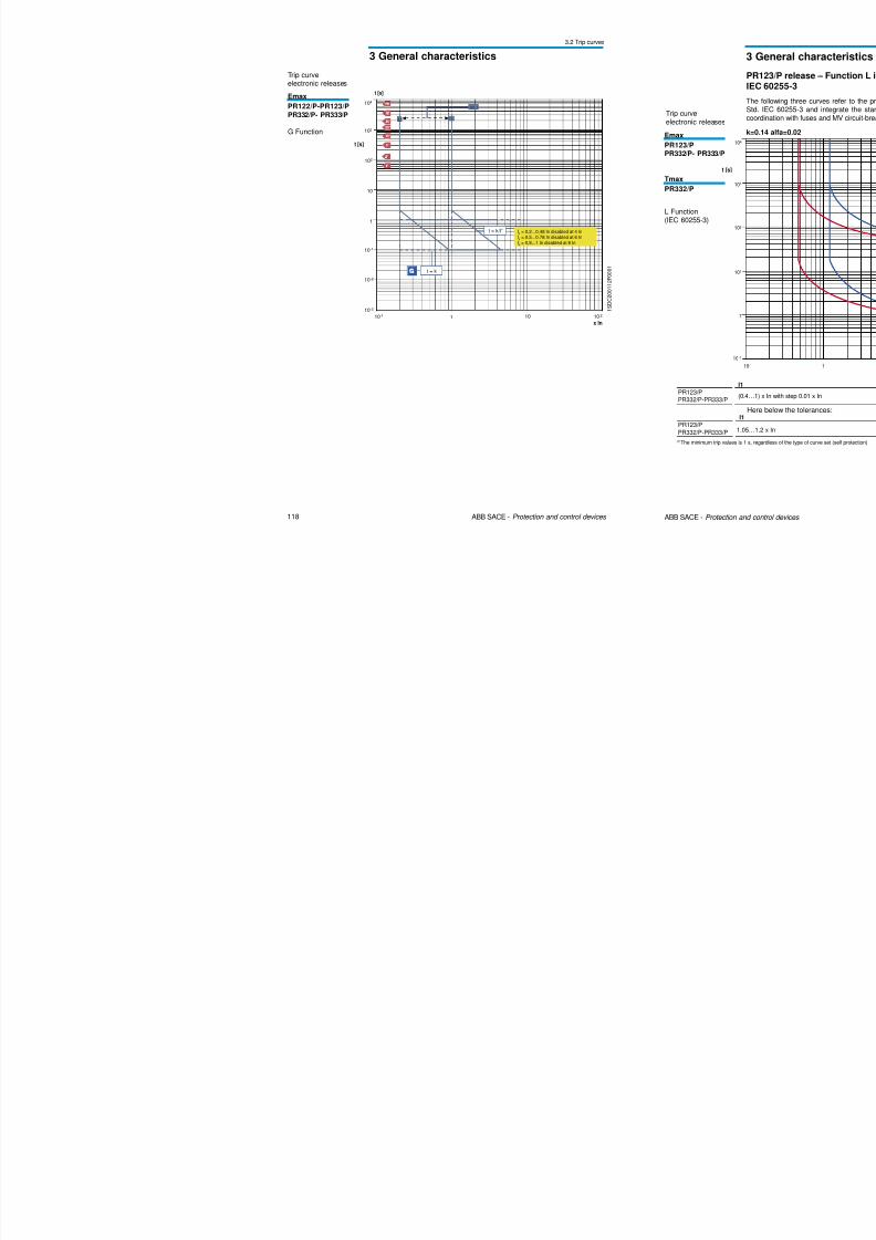
Emax
PR122/P-PR123/P
PR332/P- PR333/P
L-S-I FunctionsS inverse shorttime delay(I2t = const.)
electronic releases
3 General characteristics
3.2 Trip curves
Trip curveelectronic releases
8/3/2019 ABB Electrical Install Ti On Handbook 4th Edition
http://slidepdf.com/reader/full/abb-electrical-install-ti-on-handbook-4th-edition 62/322
118 ABB SACE - Protection and control devices
t [s]
1 10
10-1
10-2
1
10
102
103
104
10-1
10-3
0,2...1
0,2 1
t = k/I2
t = k
10 2
I4
= 0,2...0,48 In disabled at 4 In
I4
= 0,5...0,78 In disabled at 6 In
I4
= 0,8...1 In disabled at 8 In
t [s]
x In
1 S
D C 2 0 0 1 1 2 F 0 0 0 1
Emax
PR122/P-PR123/P
PR332/P- PR333/P
G Function
electronic releases
3 General characteristics
3.2 Trip curves
Trip curveelectronic releases k=13.5 alfa=1
8/3/2019 ABB Electrical Install Ti On Handbook 4th Edition
http://slidepdf.com/reader/full/abb-electrical-install-ti-on-handbook-4th-edition 63/322
120 ABB SACE - Protection and control devices
103
t [s]
1
102
104
101
10-1
10-1 1 101 102
x In
1 S D C 2 0 0 1 1 9 F 0 0 0 1
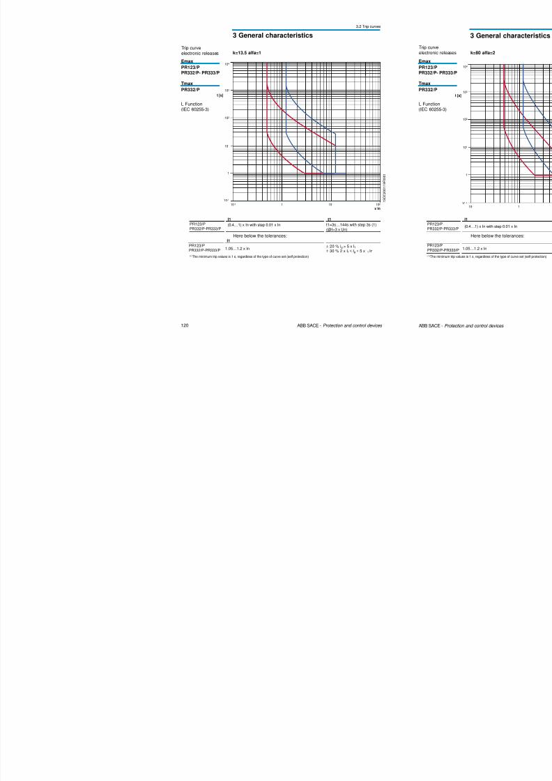
electronic releases
Emax
PR123/P
PR332/P- PR333/P
Tmax
PR332/P
L Function(IEC 60255-3)
k=13.5 alfa=1
PR123/PPR332/P-PR333/P
I1
(0.4…1) x In with step 0.01 x In
t1
t1=3s…144s with step 3s (1)
(@I=3 x Un)
Here below the tolerances:I1
1.05…1.2 x In± 20 % Ig > 5 x I1± 30 % 2 x I1 ≤ Ig ≤ 5 x I1 In
(1)The minimum trip values is 1 s, regardless of the type of curve set (self protection)
PR123/PPR332/P-PR333/P
3 General characteristics
3.2 Trip curves
Trip curveelectronic releases
PR 122/PR123 release – Other protection functions
8/3/2019 ABB Electrical Install Ti On Handbook 4th Edition
http://slidepdf.com/reader/full/abb-electrical-install-ti-on-handbook-4th-edition 64/322
122 ABB SACE - Protection and control devices
103
t [s]
1
102
10-1
104
101
10-2 1 101 102
x In10-1
0,2...0,8
D
1 S D C 2 0 0 1 2 1 F 0 0 0 1
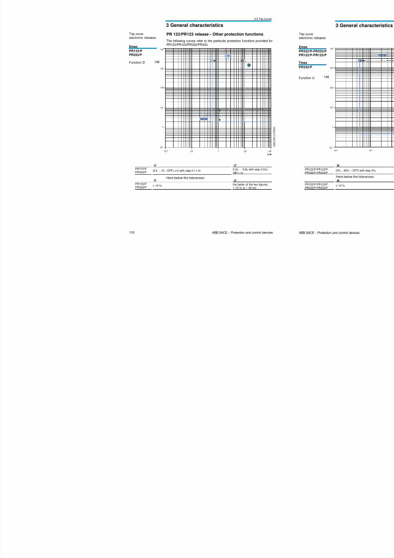
Emax
PR123/PPR333/P
Function D
PR123/PPR333/P
I7
(0.6 …10 – OFF) x In with step 0.1 x In
t7
0.2s … 0.8s with step 0.01s(@I > I7)
Here below the tolerances:
PR123/PPR333/P
I7
± 10 %
t7
the better of the two figures:± 10 % or ± 40 ms
The following curves refer to the particular protection functions provided forPR122/PR123/PR332/PR333.
3 General characteristics
3.2 Trip curves
Trip curveelectronic releases

8/3/2019 ABB Electrical Install Ti On Handbook 4th Edition
http://slidepdf.com/reader/full/abb-electrical-install-ti-on-handbook-4th-edition 65/322
124 ABB SACE - Protection and control devices
0.3
x Un0.5 0.7 0.9 1.1 1.3
103
t [s]
1
102
10-1
104
101
10-2
0,1...5
5
UV
0,1
0,950,5...0,95
0,5
1 S D C 2 0 0 1 2 3 F 0 0 0 1
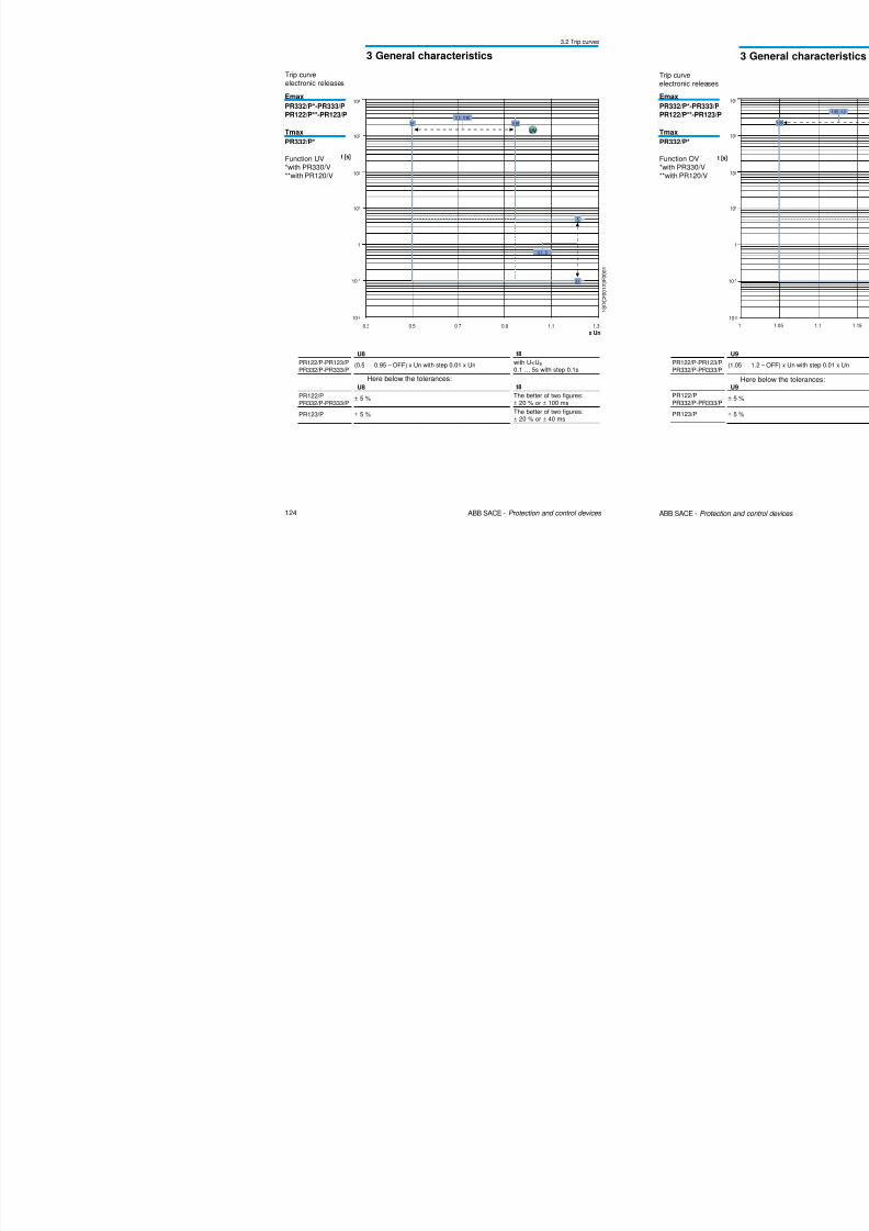
Emax
PR332/P*-PR333/P
PR122/P**-PR123/P
Tmax
PR332/P*
Function UV*with PR330/V**with PR120/V
PR122/P-PR123/PPR332/P-PR333/P
U8
(0.5 … 0.95 – OFF) x Un with step 0.01 x Un
t8
with U<U8
0.1 … 5s with step 0.1s
Here below the tolerances:
PR122/P
PR332/P-PR333/P
PR123/P
U8
± 5 %
± 5 %
t8
The better of two figures:
± 20 % or ± 100 msThe better of two figures:± 20 % or ± 40 ms
3 General characteristics
3.2 Trip curves
Trip curveelectronic releases
8/3/2019 ABB Electrical Install Ti On Handbook 4th Edition
http://slidepdf.com/reader/full/abb-electrical-install-ti-on-handbook-4th-edition 66/322
126 ABB SACE - Protection and control devices
1 S D C 2 0 0 1 2 5 F 0 0 0 1
0 1
x Un
0.2 0.4 0.6 1.2
103
t [s]
1
102
10-1
104
101
0.8
30
0,1...0,4
0,5
RV
0,5...30
0,40,1
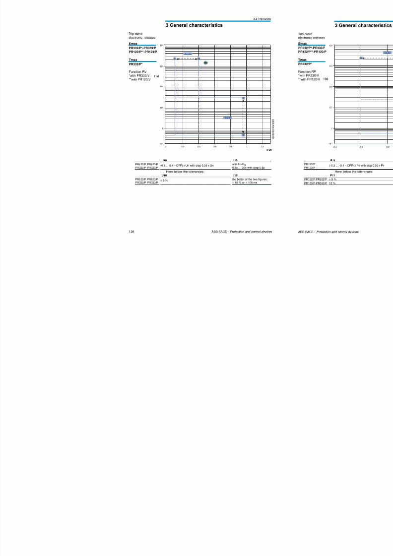
Emax
PR332/P*-PR333/P
PR122/P**-PR123/P
Tmax
PR332/P*
Function RV*with PR330/V**with PR120/V
PR122/P PR123/PPR332/P PR333/P
U10
(0.1 … 0.4 – OFF) x Un with step 0.05 x Un
t10
with U<U10
0.5s … 30s with step 0.5s
Here below the tolerances:
PR122/P PR123/P
PR332/P PR333/P
U10
± 5 %
t10
the better of the two figures:
± 10 % or ± 100 ms
3 General characteristics
3.2 Trip curves
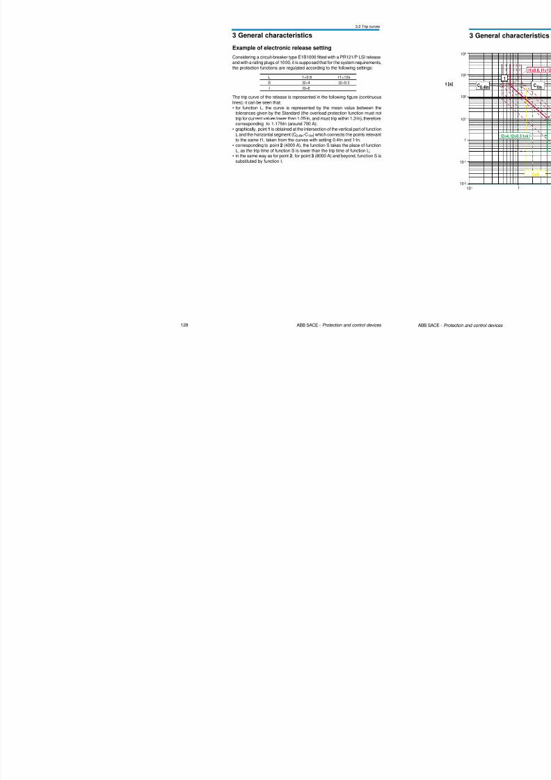
Example of electronic release setting
Considering a circuit-breaker type E1B1000 fitted with a PR121/P LSI release
8/3/2019 ABB Electrical Install Ti On Handbook 4th Edition
http://slidepdf.com/reader/full/abb-electrical-install-ti-on-handbook-4th-edition 67/322
128 ABB SACE - Protection and control devices
L I1=0.6 t1=12s
S I2=4 t2=0.3
I I3=8
Considering a circuit-breaker type E1B1000 fitted with a PR121/P LSI releaseand with a rating plugs of 1000, it is supposed that for the system requirements,the protection functions are regulated according to the following settings:
The trip curve of the release is represented in the following figure (continuous
lines): it can be seen that:• for function L, the curve is represented by the mean value between the
tolerances given by the Standard (the overload protection function must nottrip for current values lower than 1.05·ln, and must trip within 1.3·ln), thereforecorresponding to 1.175·ln (around 700 A);
• graphically, point 1 is obtained at the intersection of the vertical part of function
L and the horizontal segment (C0.4In-C1In) which connects the points relevantto the same t1, taken from the curves with setting 0.4·ln and 1·ln;
• corresponding to point 2 (4000 A), the function S takes the place of functionL, as the trip time of function S is lower than the trip time of function L;
• in the same way as for point 2, for point 3 (8000 A) and beyond, function S issubstituted by function I.
3 General characteristics
3.3 Limitation curves
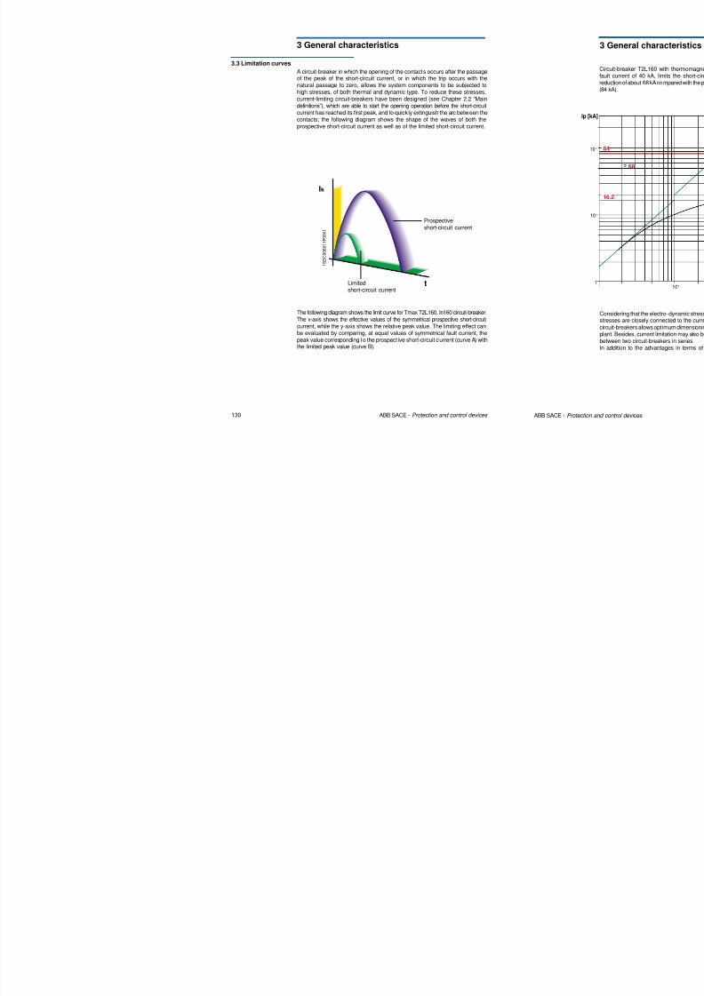
A circuit-breaker in which the opening of the contacts occurs after the passage
8/3/2019 ABB Electrical Install Ti On Handbook 4th Edition
http://slidepdf.com/reader/full/abb-electrical-install-ti-on-handbook-4th-edition 68/322
130 ABB SACE - Protection and control devices
Ik
t
1 S D C 0 0 8 0 1 1 F 0 0 0 1
p g p gof the peak of the short-circuit current, or in which the trip occurs with thenatural passage to zero, allows the system components to be subjected to
high stresses, of both thermal and dynamic type. To reduce these stresses,current-limiting circuit-breakers have been designed (see Chapter 2.2 “Maindefinitions”), which are able to start the opening operation before the short-circuitcurrent has reached its first peak, and to quickly extinguish the arc between thecontacts; the following diagram shows the shape of the waves of both theprospective short-circuit current as well as of the limited short-circuit current.
The following diagram shows the limit curve for Tmax T2L160, In160 circuit-breaker.
The x-axis shows the effective values of the symmetrical prospective short-circuit
current, while the y-axis shows the relative peak value. The limiting effect canbe evaluated by comparing, at equal values of symmetrical fault current, thepeak value corresponding to the prospect ive short-circuit current (curve A) withthe limited peak value (curve B).
Prospective
short-circuit current
Limitedshort-circuit current
3 General characteristics
3.3 Limitation curves
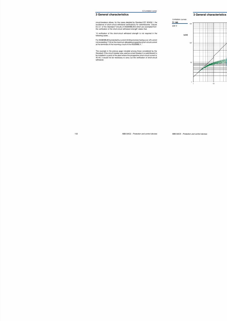
circuit-breakers allows, for the cases detailed by Standard IEC 60439-1, theavoidance of short circuit withstand verifications for switchboards Clause
8/3/2019 ABB Electrical Install Ti On Handbook 4th Edition
http://slidepdf.com/reader/full/abb-electrical-install-ti-on-handbook-4th-edition 69/322
132 ABB SACE - Protection and control devices
avoidance of short-circuit withstand verifications for switchboards. Clause8.2.3.1 of the Standard “Circuits of ASSEMBLIES which are exempted from
the verification of the short-circuit withstand strength” states that:
“A verification of the short-circuit withstand strength is not required in thefollowing cases…
For ASSEMBLIES protected by current-limiting devices having a cut-off currentnot exceeding 17 kA at the maximum allowable prospective short-circuit currentat the terminals of the incoming c ircuit of the ASSEMBLY...”
The example in the previus page included among those considered by theStandard: if the circuit-breaker was used as a main breaker in a switchboard to
be installed in a point of the plant where the prospective short-circuit current is40 kA, it would not be necessary to carry out the verification of short-circuit
withstand.
3 General characteristics
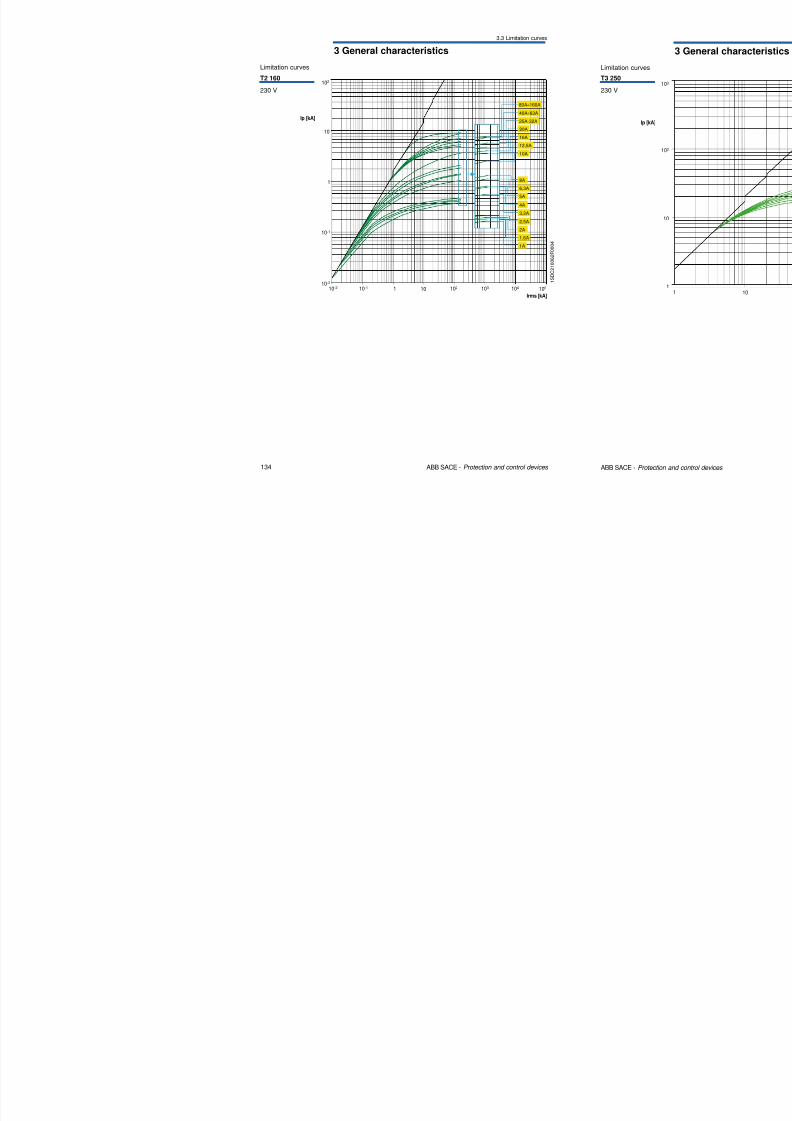
3.3 Limitation curves
Limitation curves
T2 160102
8/3/2019 ABB Electrical Install Ti On Handbook 4th Edition
http://slidepdf.com/reader/full/abb-electrical-install-ti-on-handbook-4th-edition 70/322
134 ABB SACE - Protection and control devices
1 S D C 2 1 0 0 6 2 F 0 0 0 4
230 V
Irms [kA]
10 102
1
10
Ip [kA]
105
10-1
10-2
10-2 10-1 1 103 104
8A
6,3A
5A
1A
4A
3,2A
2,5A
2A
1,6A
12,5A
10A
16A
80A÷160A
40A÷63A
25A-32A
20A
3 General characteristics
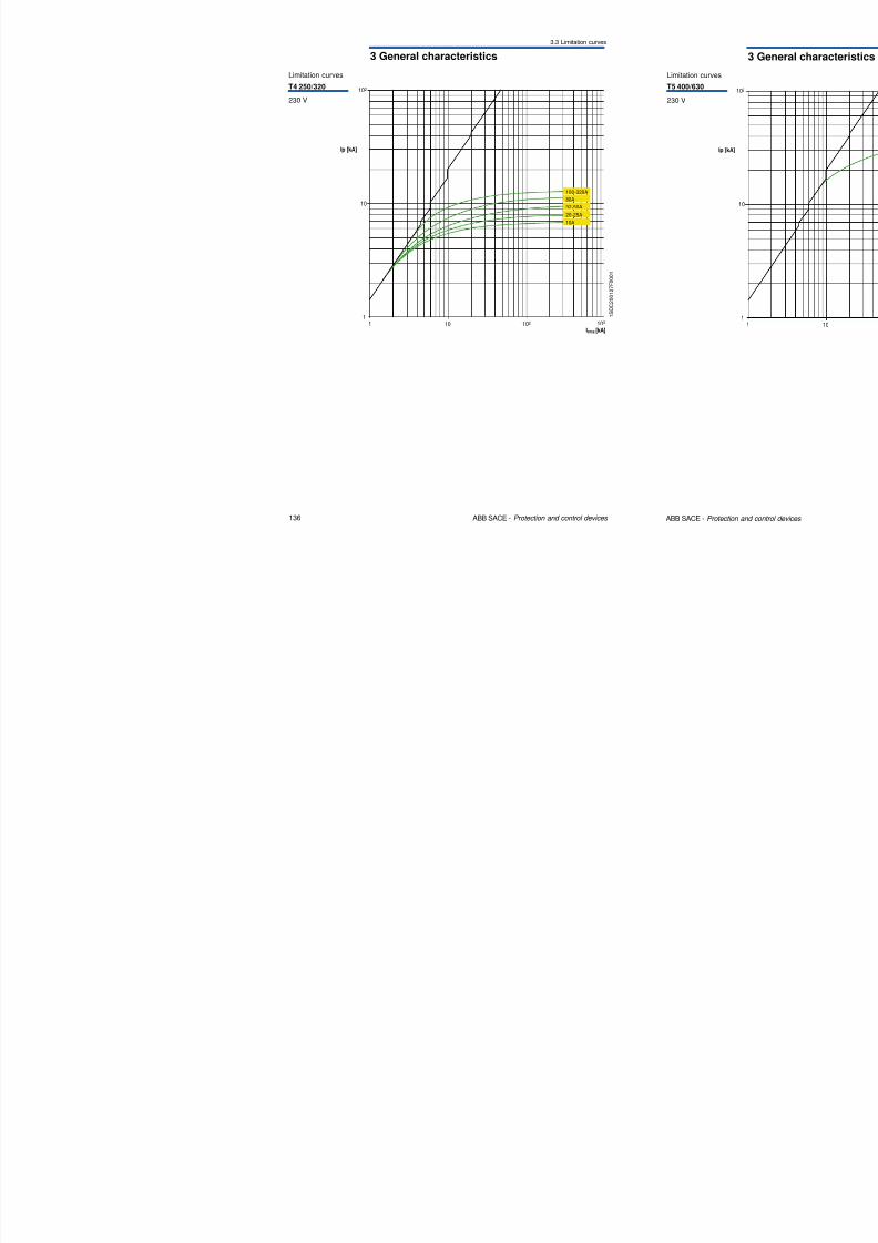
3.3 Limitation curves
102
Limitation curves
T4 250/320
8/3/2019 ABB Electrical Install Ti On Handbook 4th Edition
http://slidepdf.com/reader/full/abb-electrical-install-ti-on-handbook-4th-edition 71/322
136 ABB SACE - Protection and control devices
10
1 10 1021
103
Irms [kA]
Ip [kA]
100-320A
80A
32-50A
20-25A
10A
230 V
1 S D
C 2 0 0 1 2 7 F 0 0 0 1
3 General characteristics
3.3 Limitation curves
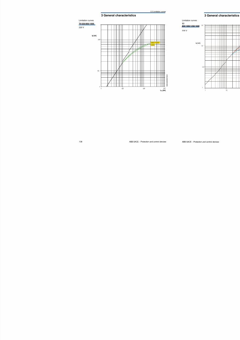
Limitation curves
T6 630/800/1000
230 V
8/3/2019 ABB Electrical Install Ti On Handbook 4th Edition
http://slidepdf.com/reader/full/abb-electrical-install-ti-on-handbook-4th-edition 72/322
138 ABB SACE - Protection and control devices
230 V
102
1 10 102
1103
Irms [kA]
Ip [kA]
1
101
800A-1000A
630A
1 S D C 2 0 0 5 5 5 F 0 0 0 1
3 General characteristics
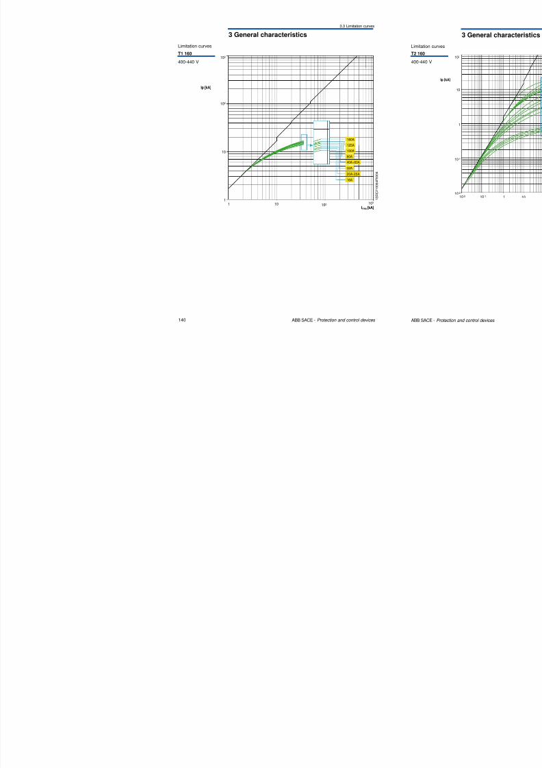
3.3 Limitation curves
Limitation curves
T1 160
400 440 V103
8/3/2019 ABB Electrical Install Ti On Handbook 4th Edition
http://slidepdf.com/reader/full/abb-electrical-install-ti-on-handbook-4th-edition 73/322
140 ABB SACE - Protection and control devices
1 S D C
2 1 0 0 6 4 F 0 0 0 4
400-440 V
1Irms [kA]
10 102 103
Ip [kA]
1
10
102
160A
125A
100A
40A÷63A
20A-25A
80A
32A
16A
3 General characteristics
3.3 Limitation curves
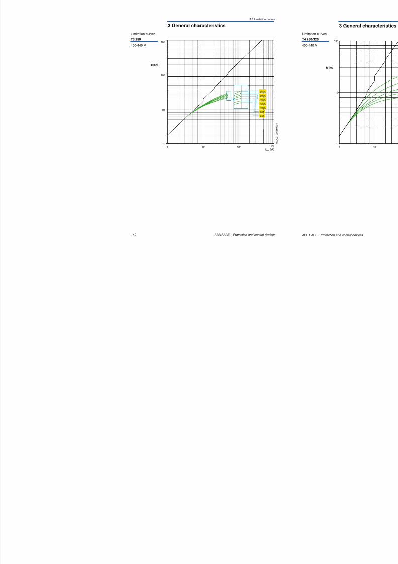
Limitation curves
T3 250
400-440 V103
8/3/2019 ABB Electrical Install Ti On Handbook 4th Edition
http://slidepdf.com/reader/full/abb-electrical-install-ti-on-handbook-4th-edition 74/322
142 ABB SACE - Protection and control devices
1 S D C 2 1 0 0 6 6 F 0 0 0 4
400 440 V
1Irms [kA]
10 1021
10
102
Ip [kA]
103
250A
200A
160A
125A
100A
80A
63A
3 General characteristics
3.3 Limitation curves
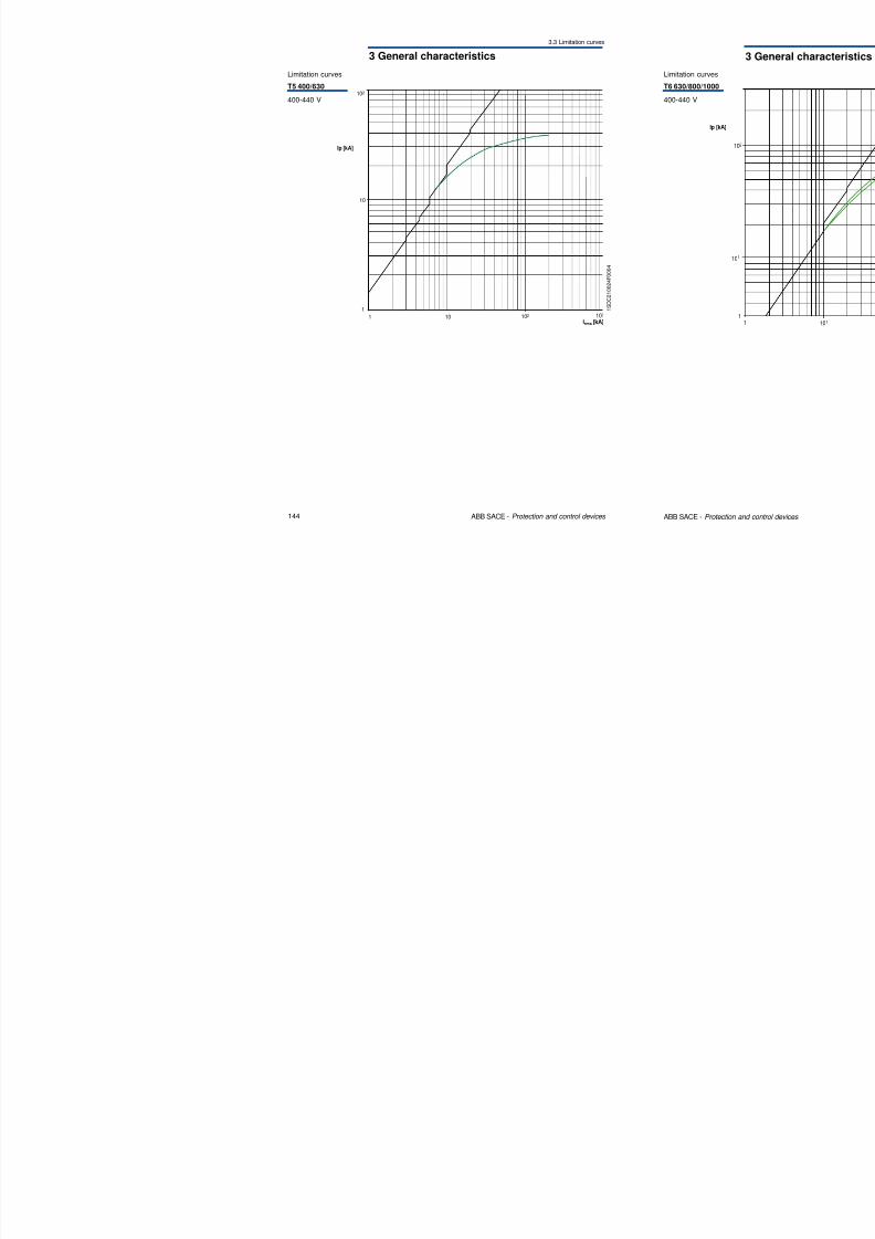
102
Limitation curves
T5 400/630
400-440 V
8/3/2019 ABB Electrical Install Ti On Handbook 4th Edition
http://slidepdf.com/reader/full/abb-electrical-install-ti-on-handbook-4th-edition 75/322
144 ABB SACE - Protection and control devices
1 101
10
102
Irms [kA]103
Ip [kA]
1
S D C 2 1 0 0 2 4 F 0 0 0 4
3 General characteristics
3.3 Limitation curves
103
Limitation curves
T7800/1000/1250/1600
8/3/2019 ABB Electrical Install Ti On Handbook 4th Edition
http://slidepdf.com/reader/full/abb-electrical-install-ti-on-handbook-4th-edition 76/322
146 ABB SACE - Protection and control devices
Ip [kA]
Irms [kA]
10 102 1031
102
10
1
T7 V
T7 S,H,L
6 G S I S 0 2 6 9
400-440 V
3 General characteristics
3.3 Limitation curves
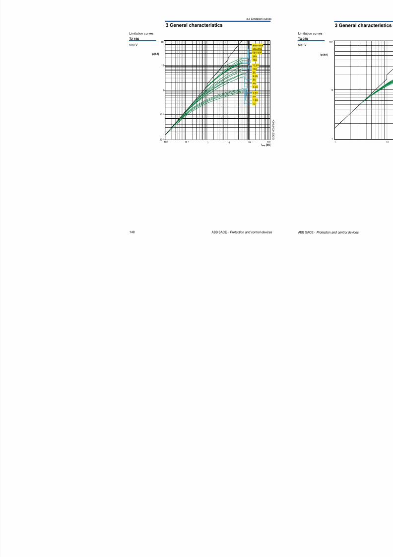
Limitation curves
T2 160
500 V102
80A÷160A

8/3/2019 ABB Electrical Install Ti On Handbook 4th Edition
http://slidepdf.com/reader/full/abb-electrical-install-ti-on-handbook-4th-edition 77/322
148 ABB SACE - Protection and control devices
1 10
1
102
Irms [kA]10310-110-2
10-1
10-2
10
Ip [kA]
2A
2,5A
1A
1,6A
3,2A
4A
5A
6,3A
8A
10A
12,5A
16A
20A
25A-32A
40A÷63A
1
S D C 2 1 0 0 3 0 F 0 0 0 4
3 General characteristics
3.3 Limitation curves
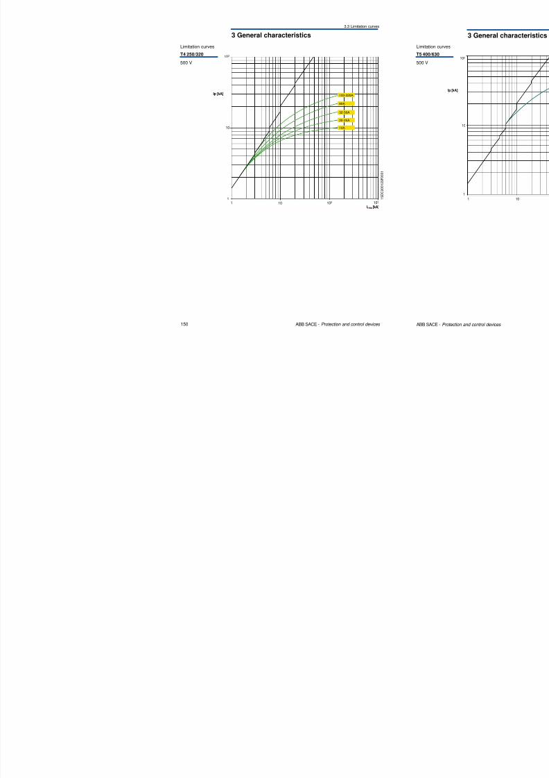
Limitation curves
T4 250/320
500 V
102
8/3/2019 ABB Electrical Install Ti On Handbook 4th Edition
http://slidepdf.com/reader/full/abb-electrical-install-ti-on-handbook-4th-edition 78/322
150 ABB SACE - Protection and control devices
10
1 10 1021
103
Irms [kA]
Ip [kA] 100-320A
80A
32-50A
20-25A
10A
1 S D C 2 0 0 1 2 9 F 0 0 0 1
3 General characteristics
3.3 Limitation curves
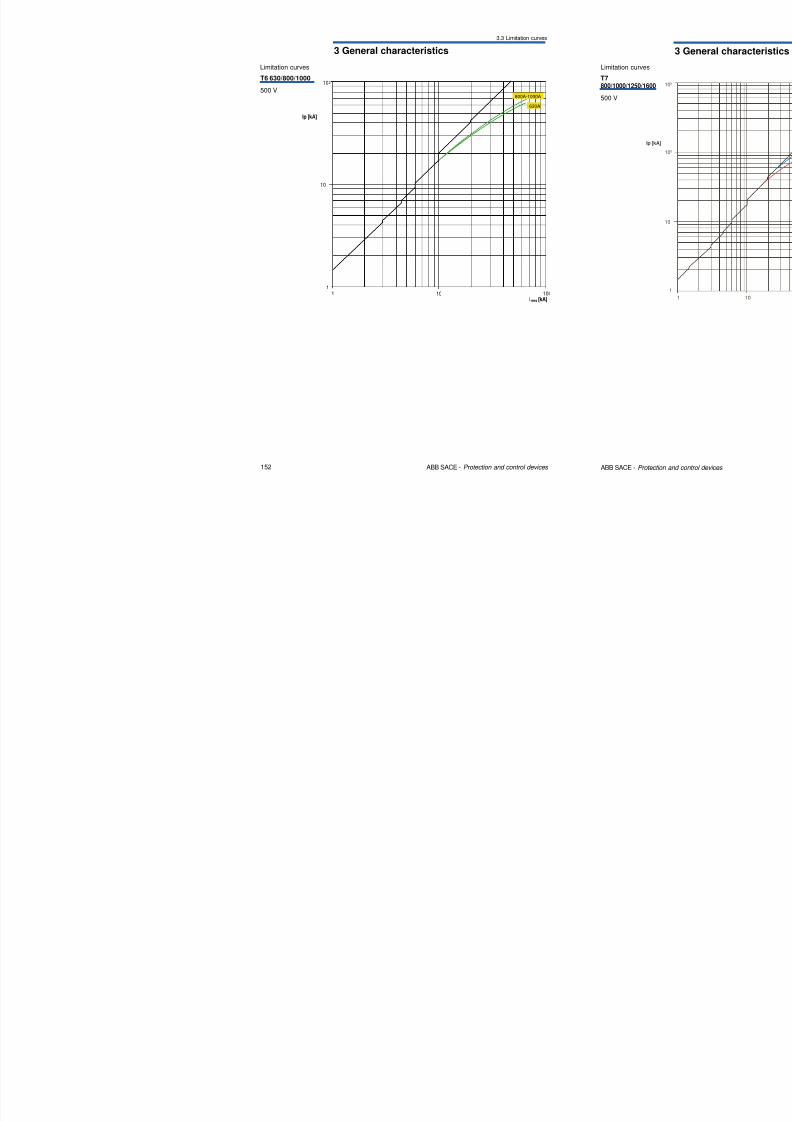
Limitation curves
T6 630/800/1000
500 V
102
800A-1000A
8/3/2019 ABB Electrical Install Ti On Handbook 4th Edition
http://slidepdf.com/reader/full/abb-electrical-install-ti-on-handbook-4th-edition 79/322
152 ABB SACE - Protection and control devices
1 10 102
1
Irms [kA]
Ip [kA]
10
800A 1000A
630A
3 General characteristics
3.3 Limitation curves
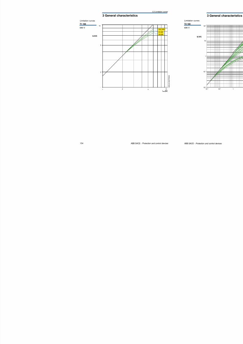
Limitation curves
T1 160
690 V10
100÷160A
8/3/2019 ABB Electrical Install Ti On Handbook 4th Edition
http://slidepdf.com/reader/full/abb-electrical-install-ti-on-handbook-4th-edition 80/322
154 ABB SACE - Protection and control devices
1 S
D C 2 1 0 0 6 7 F 0 0 0 4
1Irms [kA]
2 51
2
5
Ip [kA]
10
16÷40A50÷80A
3 General characteristics
3.3 Limitation curves
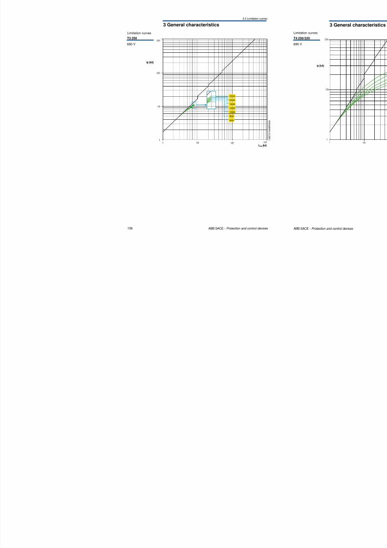
Limitation curves
T3 250
690 V103
8/3/2019 ABB Electrical Install Ti On Handbook 4th Edition
http://slidepdf.com/reader/full/abb-electrical-install-ti-on-handbook-4th-edition 81/322
156 ABB SACE - Protection and control devices
1 S D C 2 1 0 0 6 9 F 0 0 0 4
1Irms [kA]
10 102
1
10
102
Ip [kA]
103
250A
200A
160A
125A
100A
80A
63A
3 General characteristics
3.3 Limitation curves
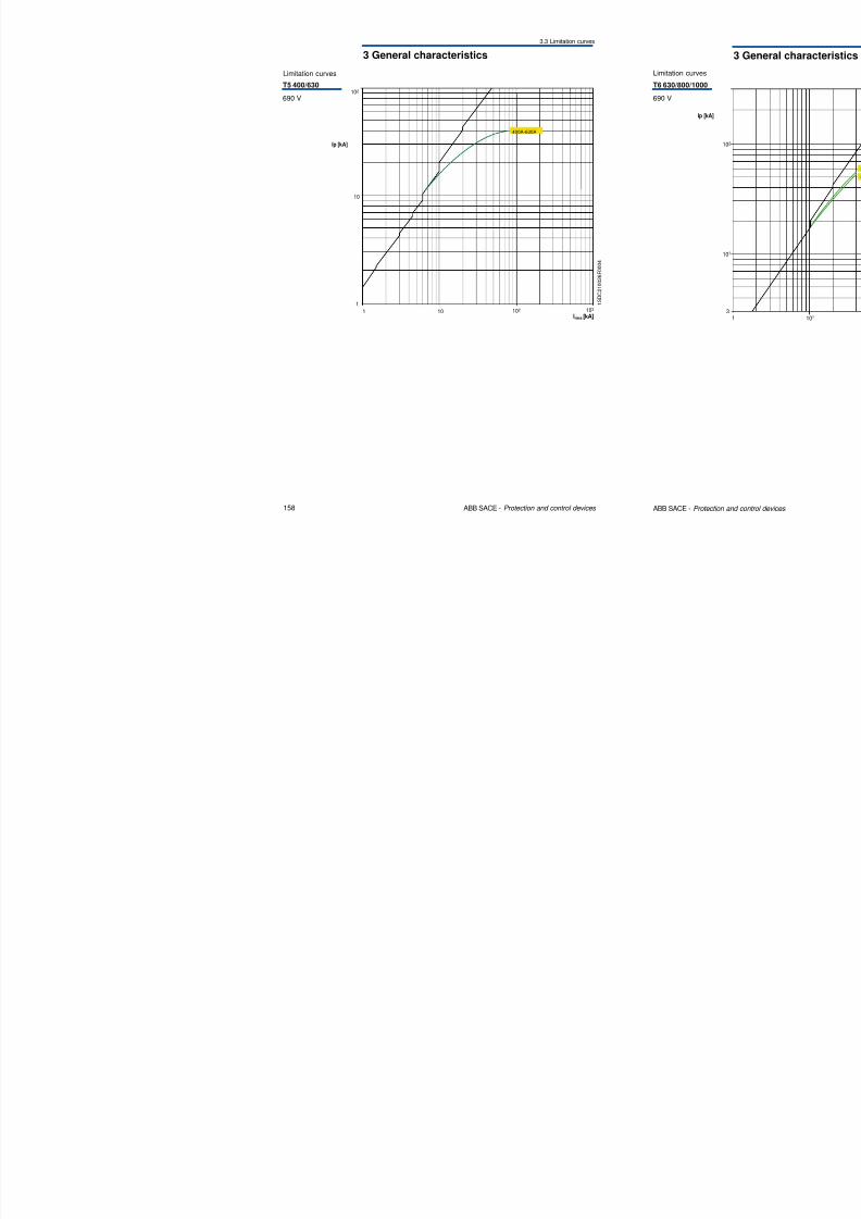
102
Limitation curves
T5 400/630
690 V
8/3/2019 ABB Electrical Install Ti On Handbook 4th Edition
http://slidepdf.com/reader/full/abb-electrical-install-ti-on-handbook-4th-edition 82/322
158 ABB SACE - Protection and control devices
1 10
1
10
102
Irms [kA]103
Ip [kA]
400A-630A
1 S D C 2 1 0 0 2 6 F 0 0 0 4
3 General characteristics
3.3 Limitation curves
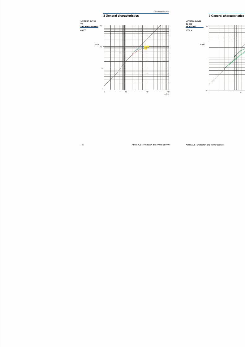
103
Limitation curves
T7800/1000/1250/1600
690 V
8/3/2019 ABB Electrical Install Ti On Handbook 4th Edition
http://slidepdf.com/reader/full/abb-electrical-install-ti-on-handbook-4th-edition 83/322
160 ABB SACE - Protection and control devices
Ip [kA]
Irms [kA]
10 102 1031
102
10
1
T7 V
T7 S,H,L
3 General characteristics
3.3 Limitation curves
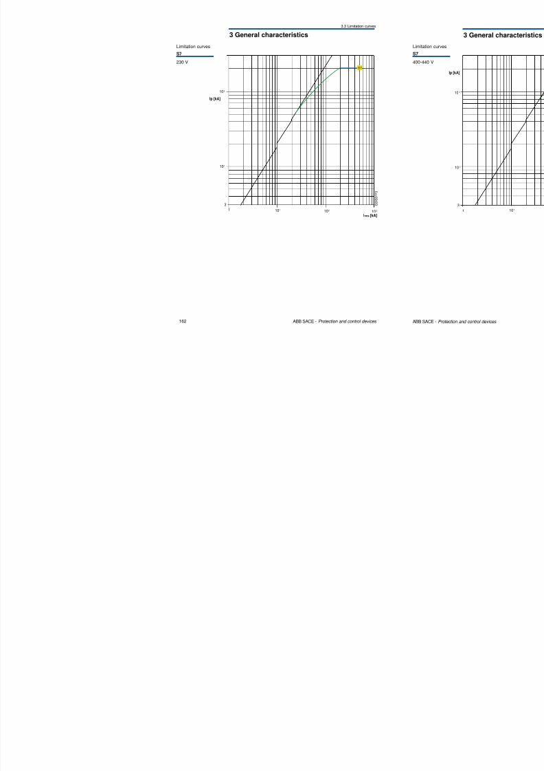
S7
Limitation curves
S7
230 V
8/3/2019 ABB Electrical Install Ti On Handbook 4th Edition
http://slidepdf.com/reader/full/abb-electrical-install-ti-on-handbook-4th-edition 84/322
162 ABB SACE - Protection and control devices
G S I S 0 2 2 3
Ip [kA]
3
1
Irms [kA]103102101
101
102
3 General characteristics
3.3 Limitation curves
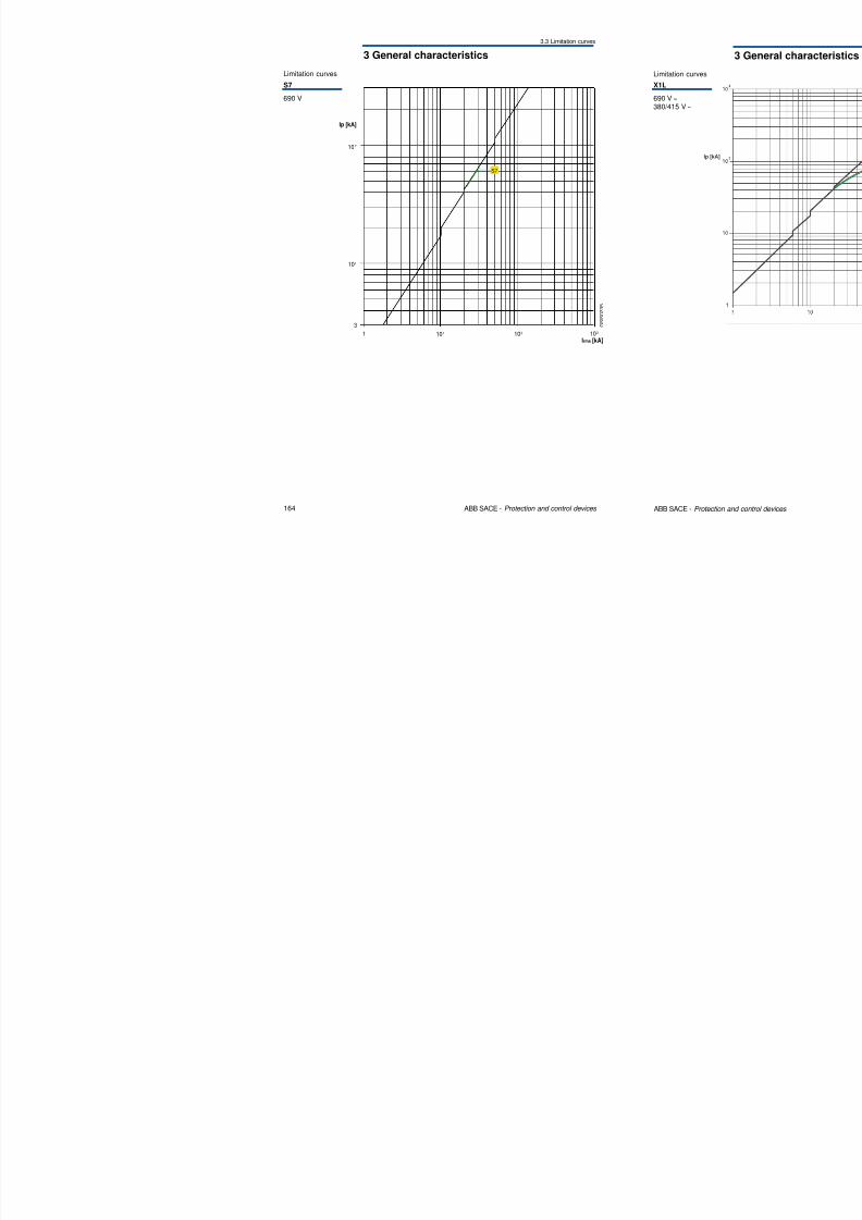
Limitation curves
S7
690 V
8/3/2019 ABB Electrical Install Ti On Handbook 4th Edition
http://slidepdf.com/reader/full/abb-electrical-install-ti-on-handbook-4th-edition 85/322
164 ABB SACE - Protection and control devices
G S I S 0 2 3
5
Ip [kA]
1
S7
Irms [kA]103102101
102
101
3
3 General characteristics
3.3 Limitation curves
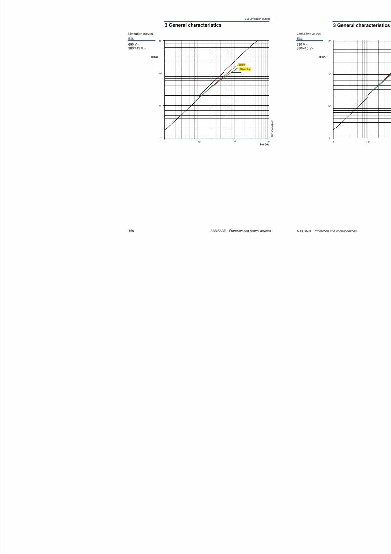
103
Limitation curves
E2L
690 V ~380/415 V ~
8/3/2019 ABB Electrical Install Ti On Handbook 4th Edition
http://slidepdf.com/reader/full/abb-electrical-install-ti-on-handbook-4th-edition 86/322
166 ABB SACE - Protection and control devices
Ip [kA]
101
1
102
1Irms [kA]
103101 102
380/415 V
690 V
1 S D C 2 0 0 0 9 2 F 0 0 0 1
3 General characteristics
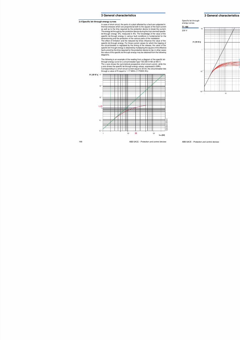
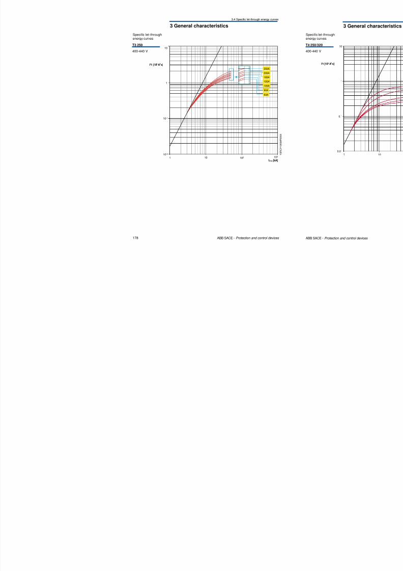
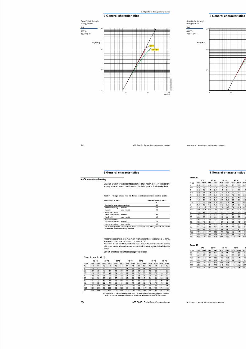
3.4 Specific let- through energy curves
In case of short-circuit, the parts of a plant affected by a fault are subjected tothermal stresses which are proportional both to the square of the fault currentas well as to the time required by the protection device to break the current.The energy let through by the protection device during the trip is termed “specific
8/3/2019 ABB Electrical Install Ti On Handbook 4th Edition
http://slidepdf.com/reader/full/abb-electrical-install-ti-on-handbook-4th-edition 87/322
168 ABB SACE - Protection and control devices
1 S D C 0 0 8 0 1 3 F 0 0 0 1
201
1.17
Irms [kA]
103
102101
102
101
1
10-1
10-2
I2t [10 A s]6 2
let-through energy” (I2t), measured in A2s. The knowledge of the value of thespecific let-through energy in various fault conditions is fundamental for thedimensioning and the protection of the various parts of the installation.The effect of limitation and the reduced trip times influence the value of thespecific let-through energy. For those current values for which the tripping ofthe circuit-breaker is regulated by the timing of the release, the value of the
specific let-through energy is obtained by multiplying the square of the effectivefault current by the time required for the protection device to trip; in other casesthe value of the specific let-through energy may be obtained from the followingdiagrams.
The following is an example of the reading from a diagram of the specific let-through energy curve for a circuit-breaker type T3S 250 In160 at 400 V.The x-axis shows the symmetrical prospective short-circuit current, while they-axis shows the specific let-through energy values, expressed in MA2s.Corresponding to a short-circuit current equal to 20 kA, the circuit-breaker letsthrough a value of I2t equal to 1.17 MA2s (1170000 A2s).
3 General characteristics
3.4 Specific let-through energy curves
Specific let-throughenergy curves
80A÷160A
40A÷63A
1T2 160
230 V
8/3/2019 ABB Electrical Install Ti On Handbook 4th Edition
http://slidepdf.com/reader/full/abb-electrical-install-ti-on-handbook-4th-edition 88/322
170 ABB SACE - Protection and control devices
T S T M 0 0 1 3
1A1,6A
2A
2,5A
3,2A4A
5A
6,3A
8A
10A
12,5A
16A
40A÷63A
25A-32A
20A
Irms [kA]
10 -2
10 -1
10 -3
10 -4
10 -5
10 -6
10 -2 10 -1 1 101 102 103 104 105
I2t [10 A s]6 2
3 General characteristics
3.4 Specific let-through energy curves
10
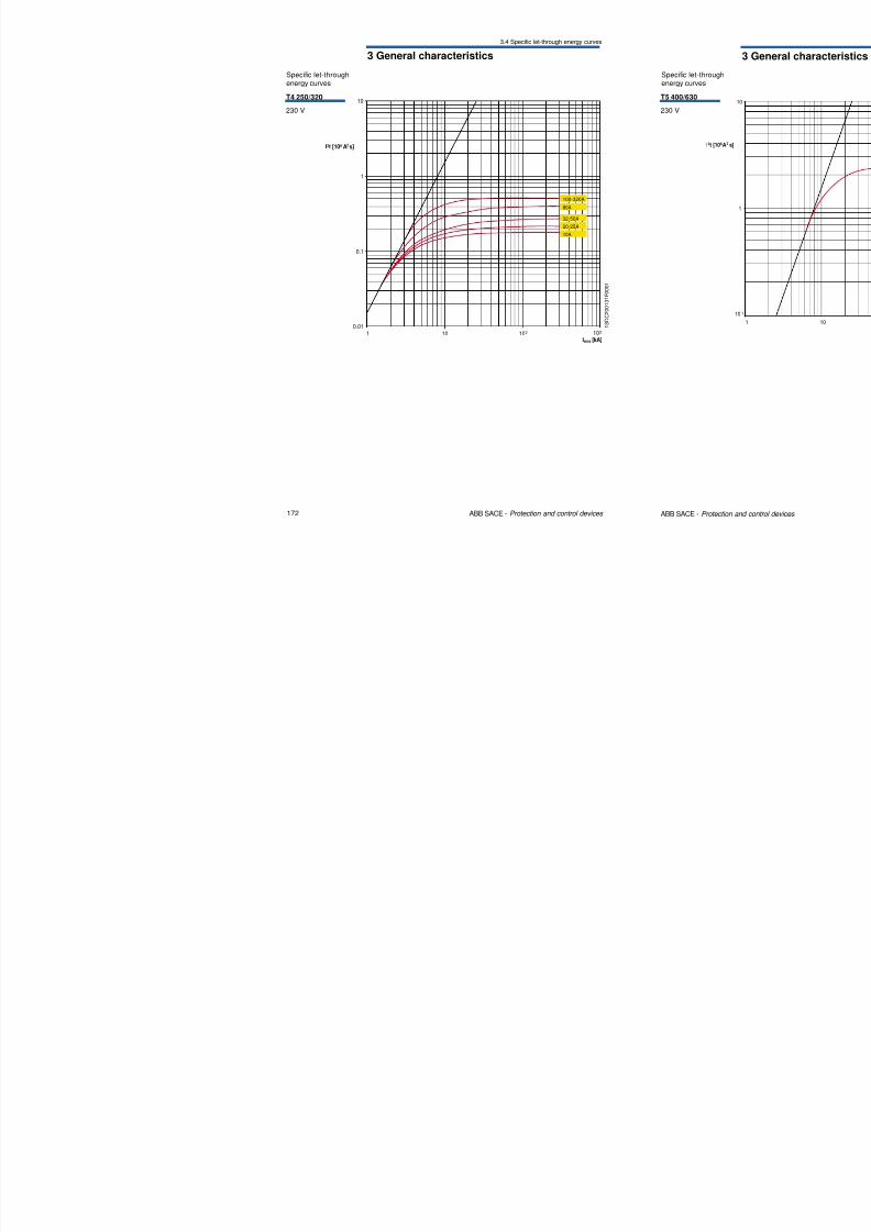
Specific let-throughenergy curves
T4 250/320
230 V
8/3/2019 ABB Electrical Install Ti On Handbook 4th Edition
http://slidepdf.com/reader/full/abb-electrical-install-ti-on-handbook-4th-edition 89/322
172 ABB SACE - Protection and control devices
1 10 102
0.01103
Irms [kA]
1
0.1
100-320A
80A
32-50A
20-25A
10A
I2t [10 A s]6 2
1 S D C 2 0 0 1 3 1 F 0 0 0 1
3 General characteristics
3.4 Specific let-through energy curves
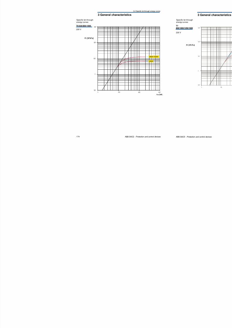
Specific let-throughenergy curves
T6 630/800/1000
230 V
103
8/3/2019 ABB Electrical Install Ti On Handbook 4th Edition
http://slidepdf.com/reader/full/abb-electrical-install-ti-on-handbook-4th-edition 90/322
174 ABB SACE - Protection and control devices
1
1
102
101
10 -1
101 102
Irms [kA]
103
I2t [10 A s]6 2
800A-1000A
630A
3 General characteristics
3.4 Specific let-through energy curves
10
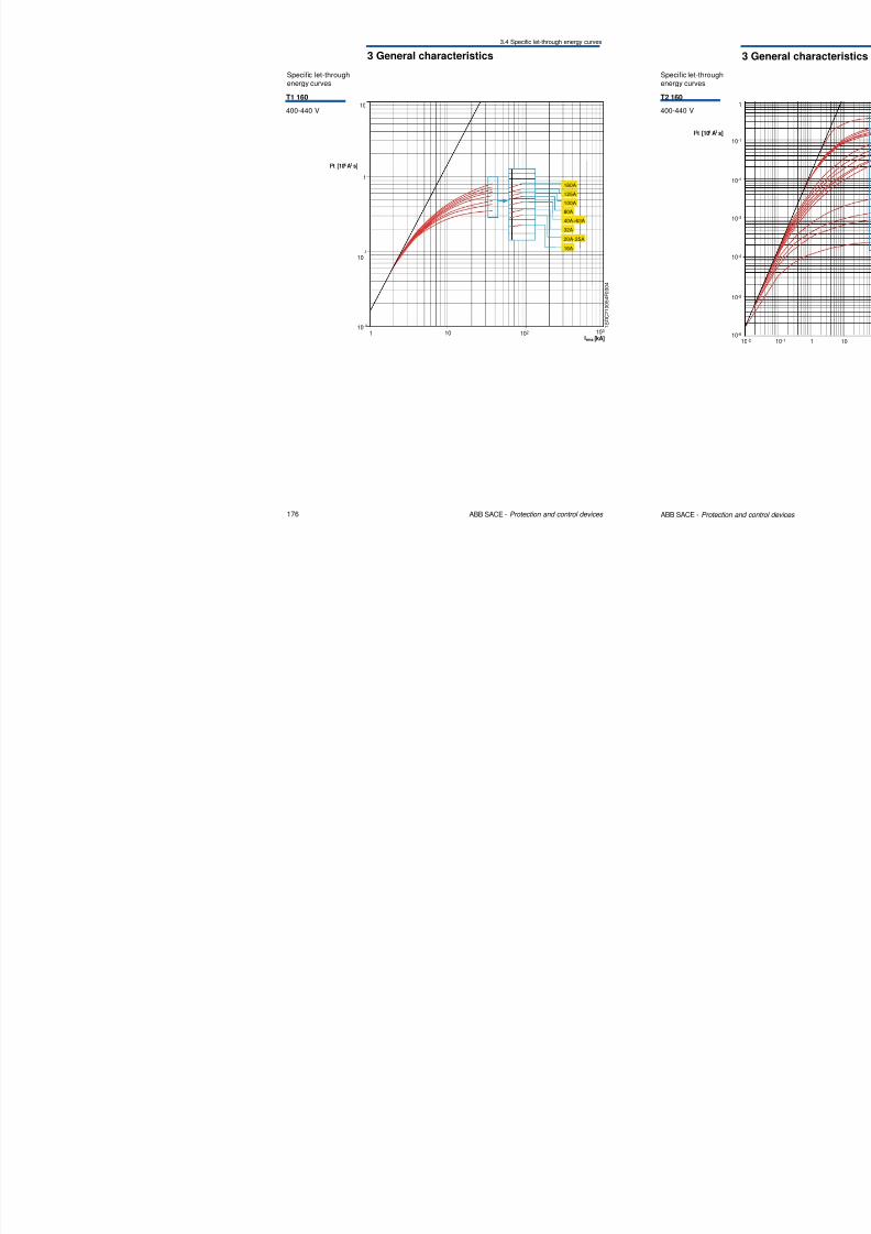
Specific let-throughenergy curves
T1 160
400-440 V
8/3/2019 ABB Electrical Install Ti On Handbook 4th Edition
http://slidepdf.com/reader/full/abb-electrical-install-ti-on-handbook-4th-edition 91/322
176 ABB SACE - Protection and control devices
1 S D C 2
1 0 0 5 4 F 0 0 0 4
1Irms [kA]
10 102 10310
10
1
-2
-1
160A
125A
100A
40A÷63A
20A-25A
80A
32A
16A
I2t [10 A s]6 2
3 General characteristics
3.4 Specific let-through energy curves
10
Specific let-throughenergy curves
T3 250
400-440 V
8/3/2019 ABB Electrical Install Ti On Handbook 4th Edition
http://slidepdf.com/reader/full/abb-electrical-install-ti-on-handbook-4th-edition 92/322
178 ABB SACE - Protection and control devices
1 S D C 2 1 0 0 5 6 F 0 0 0 4
1Irms [kA]
10 102 103
1
10-2
10-1
250A
200A
160A
125A
100A
80A
63A
I2t [10 A s]6 2
3 General characteristics
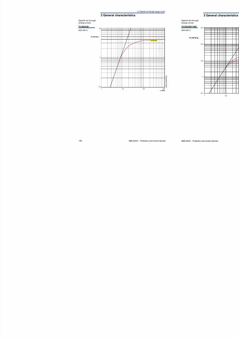
3.4 Specific let-through energy curves
Specific let-throughenergy curves
T5 400/630
400-440 V10
8/3/2019 ABB Electrical Install Ti On Handbook 4th Edition
http://slidepdf.com/reader/full/abb-electrical-install-ti-on-handbook-4th-edition 93/322
180 ABB SACE - Protection and control devices
1 S D
C 2 1 0 0 2 0 F 0 0 0 4
1 10 102
Irms [kA]103
1
10-1
I2t [10 A s]6 2
400-630A
3 General characteristics
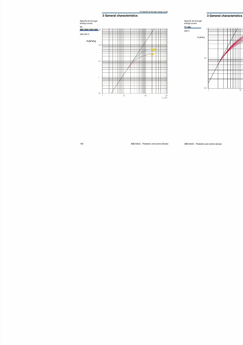
3.4 Specific let-through energy curves
103
Specific let-throughenergy curves
T7800/1000/1250/1600
400-440 V
8/3/2019 ABB Electrical Install Ti On Handbook 4th Edition
http://slidepdf.com/reader/full/abb-electrical-install-ti-on-handbook-4th-edition 94/322
182 ABB SACE - Protection and control devices
Irms [kA]
10 102 1031
102
10
1
10-1
T7 V
T7 S,H,L
I2t [10 A s]6 2
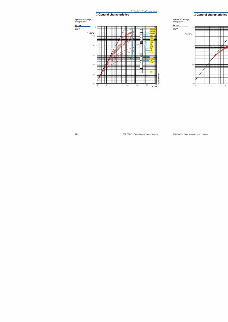
3 General characteristics
3.4 Specific let-through energy curves
Specific let-throughenergy curves
T2 160
500 V1
80A÷160A
40A÷63A
25A-32AI2t [10 A s]6 2
8/3/2019 ABB Electrical Install Ti On Handbook 4th Edition
http://slidepdf.com/reader/full/abb-electrical-install-ti-on-handbook-4th-edition 95/322
184 ABB SACE - Protection and control devices
1 S D
C 2 1 0 0 2 9 F 0 0 0 4
1 10 102
10-1
10-2
10-2 10310-1
10-3
10-4
10-5
10-6
Irms [kA]
104
20A
16A
12,5A
5A
6,3A
25A 32A
10A
8A
4A
3,2A
2A
2,5A
1A
1,6A
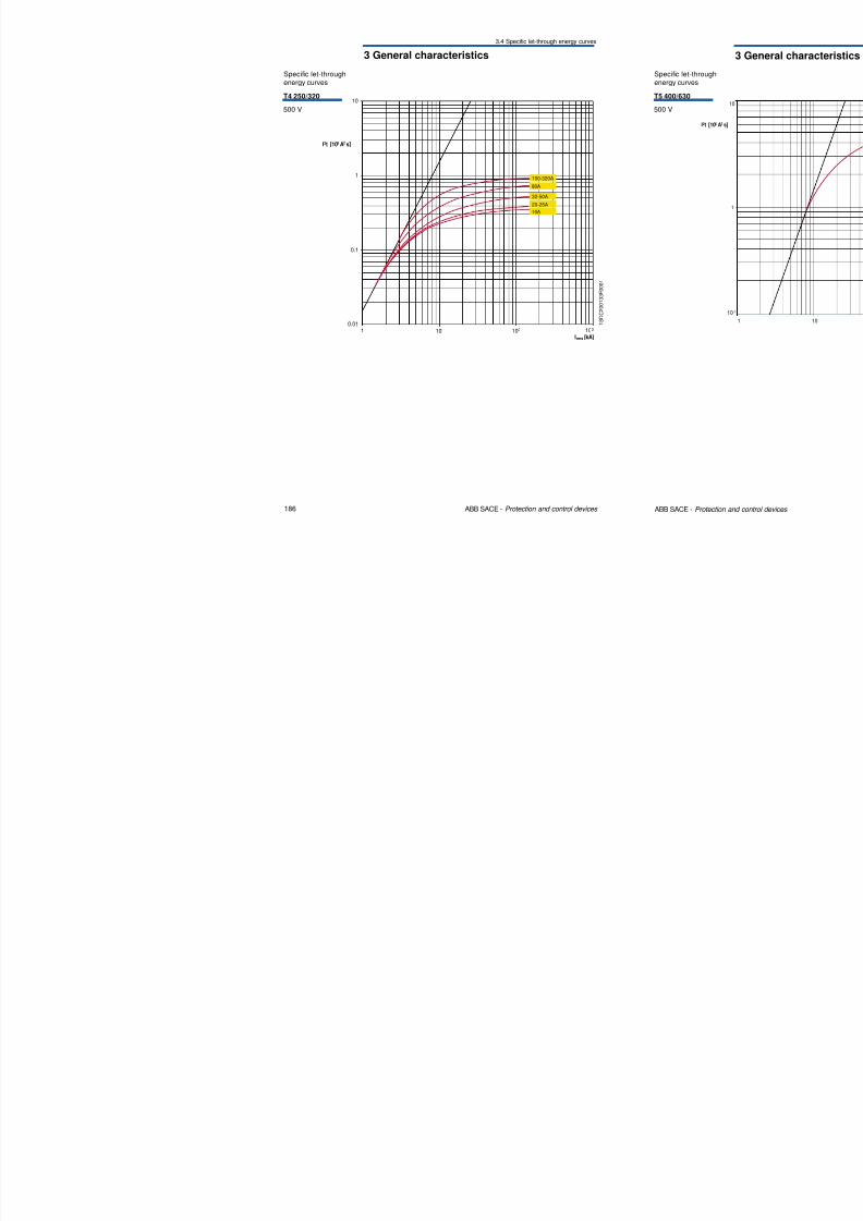
3 General characteristics
3.4 Specific let-through energy curves
Specific let-throughenergy curves
T4 250/320
500 V
10
8/3/2019 ABB Electrical Install Ti On Handbook 4th Edition
http://slidepdf.com/reader/full/abb-electrical-install-ti-on-handbook-4th-edition 96/322
186 ABB SACE - Protection and control devices
1 S D C 2
0 0 1 3 3 F 0 0 0 1
1 10 102
0.01103
Irms [kA]
1
0.1
100-320A
80A
32-50A
20-25A
10A
I2t [10 A s]6 2
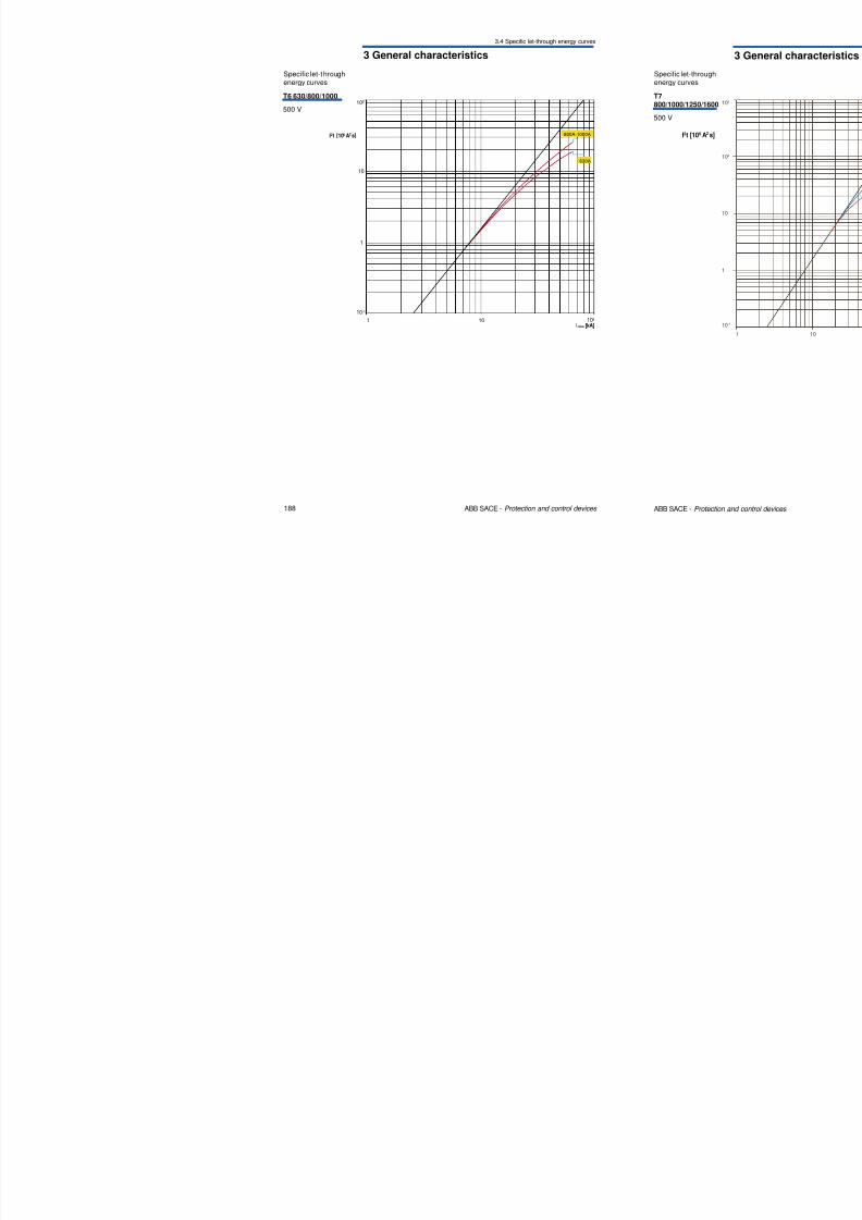
3 General characteristics
3.4 Specific let-through energy curves
Specific let-throughenergy curves
T6 630/800/1000
500 V102
8/3/2019 ABB Electrical Install Ti On Handbook 4th Edition
http://slidepdf.com/reader/full/abb-electrical-install-ti-on-handbook-4th-edition 97/322
188 ABB SACE - Protection and control devices
1 10 102
1
10
10-1
Irms [kA]
800A-1000A
630A
I2t [10 A s]6 2
3 General characteristics
3.4 Specific let-through energy curves
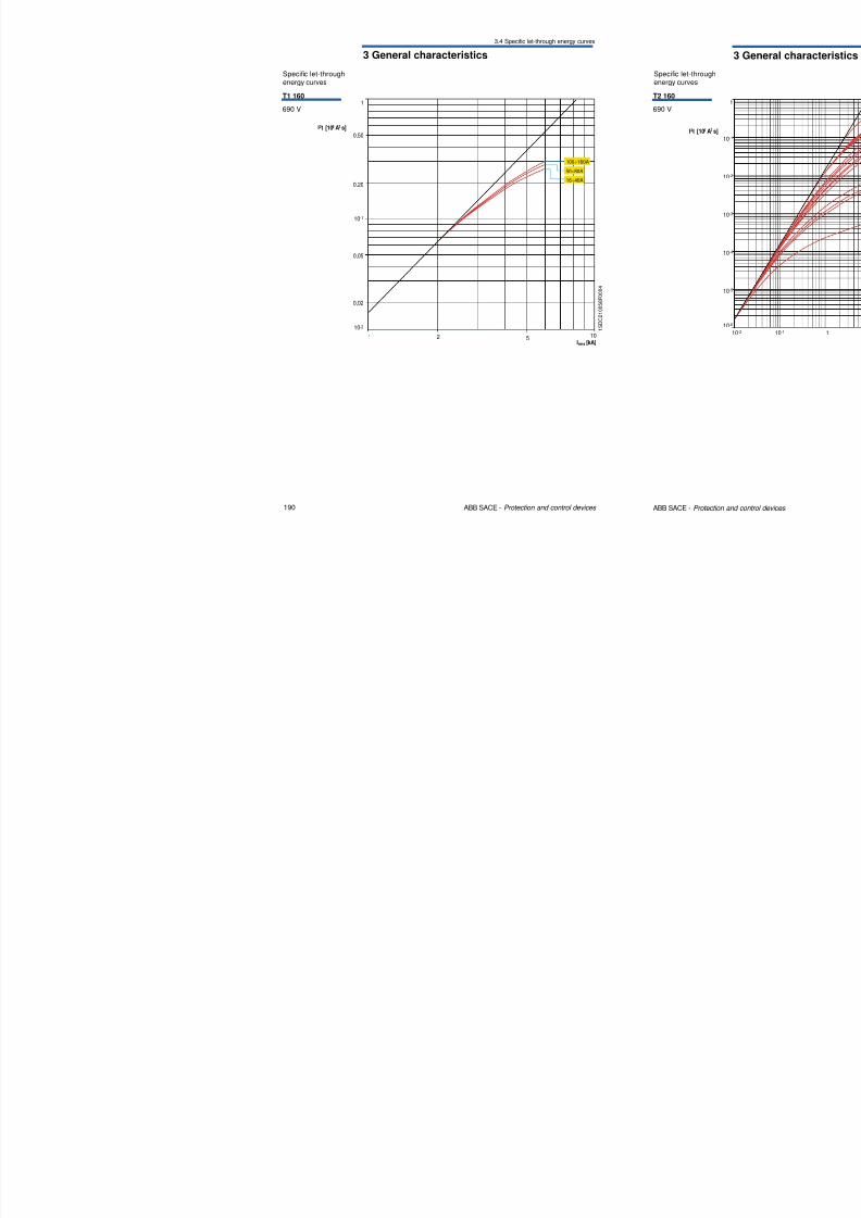
1
I2t [10 A s]6 2
Specific let-throughenergy curves
T1 160
690 V
8/3/2019 ABB Electrical Install Ti On Handbook 4th Edition
http://slidepdf.com/reader/full/abb-electrical-install-ti-on-handbook-4th-edition 98/322
190 ABB SACE - Protection and control devices
1 S D C 2 1 0
0 5 8 F 0 0 0 4
1Irms [kA]
2 5 10
0,50
0,20
10-1
0,05
0,02
10-2
16÷40A
50÷80A
100÷160A
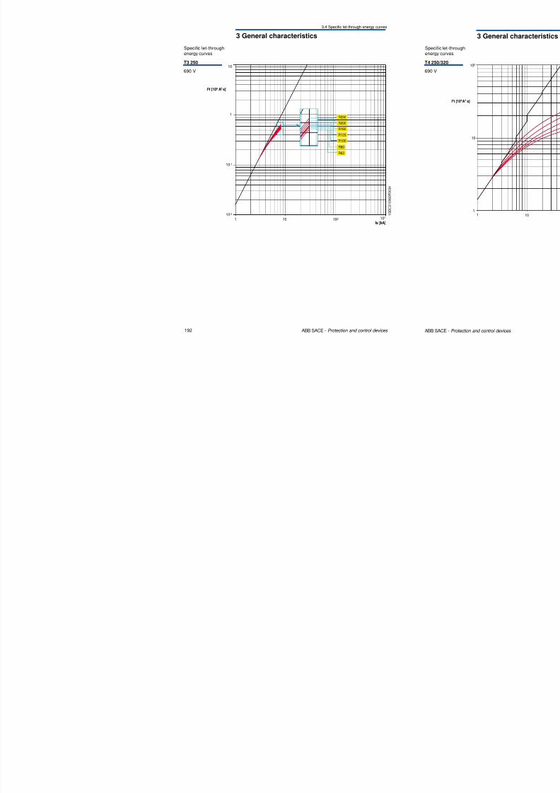
3 General characteristics
3.4 Specific let-through energy curves
Specific let-throughenergy curves
T3 250
690 V10
8/3/2019 ABB Electrical Install Ti On Handbook 4th Edition
http://slidepdf.com/reader/full/abb-electrical-install-ti-on-handbook-4th-edition 99/322
192 ABB SACE - Protection and control devices
1 S D C 2 1 0
0 6 0 F 0 0 0 4
1Is [kA]
10 102 103
1
10-2
10-1
R250
R200
R160
R125
R100
R80
R63
I2t [10 A s]6 2
3 General characteristics
3.4 Specific let-through energy curves
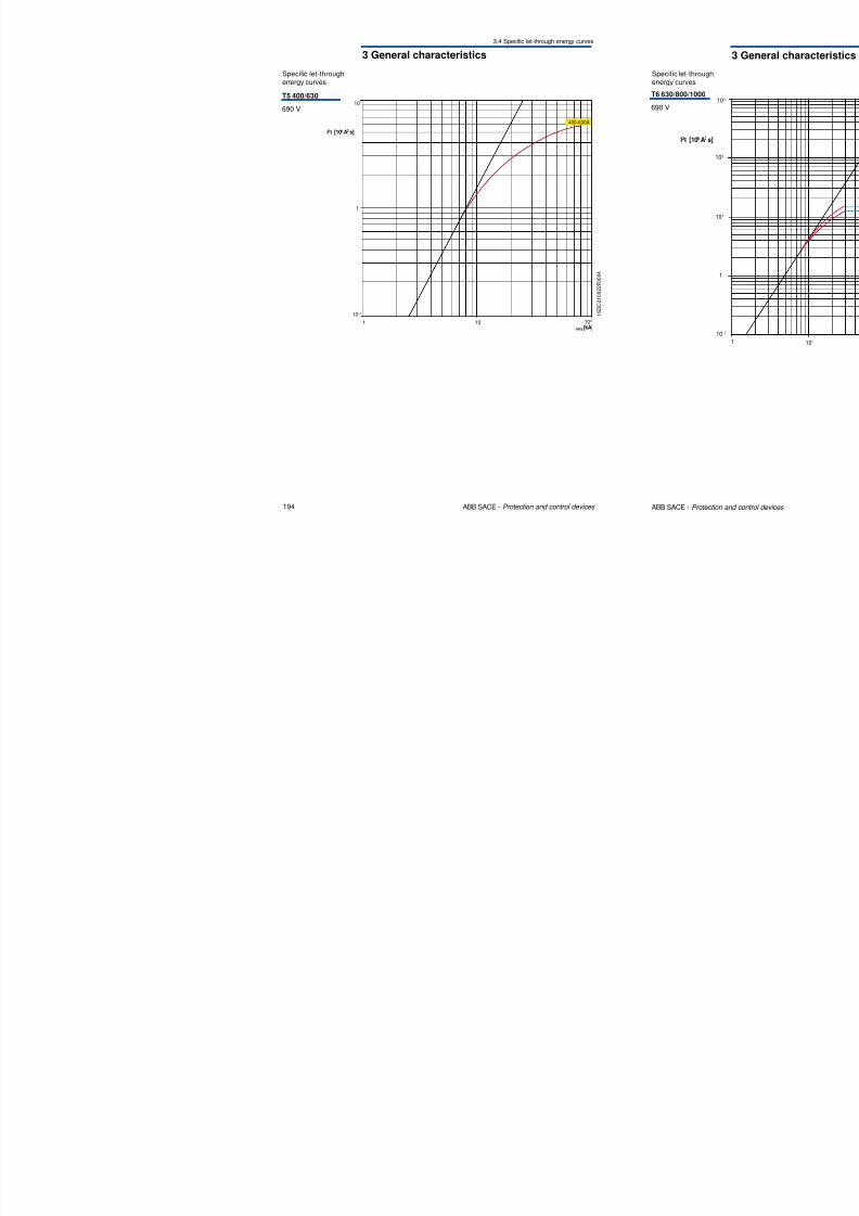
Specific let-throughenergy curves
T5 400/630
690 V10
I2t [10 A s]6 2
400-630A
8/3/2019 ABB Electrical Install Ti On Handbook 4th Edition
http://slidepdf.com/reader/full/abb-electrical-install-ti-on-handbook-4th-edition 100/322
194 ABB SACE - Protection and control devices
1 S D C 2 1 0 0 2 2 F 0 0 0 4
1 10 102
Irms [kA]
1
10-1
3 General characteristics
3.4 Specific let-through energy curves
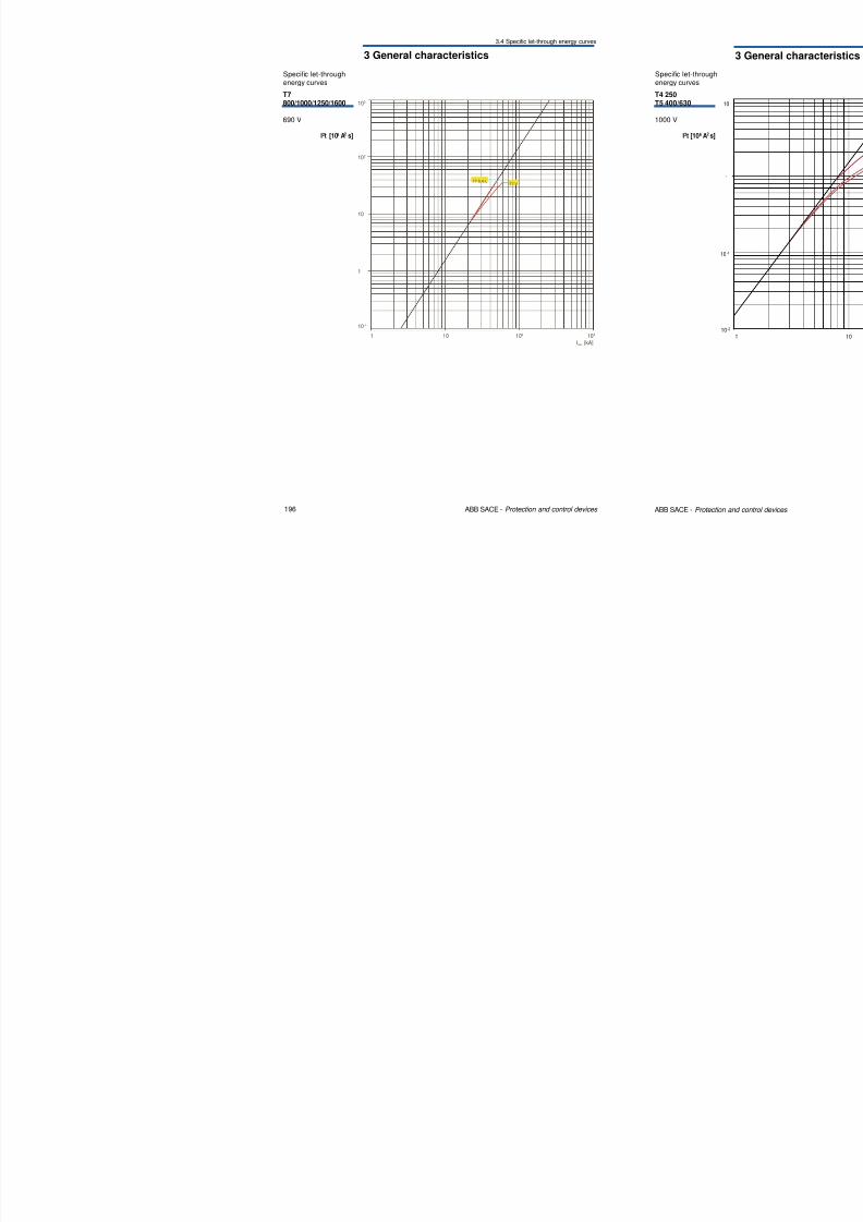
103
I2t [10 A s]6 2
Specific let-throughenergy curves
T7800/1000/1250/1600
690 V
8/3/2019 ABB Electrical Install Ti On Handbook 4th Edition
http://slidepdf.com/reader/full/abb-electrical-install-ti-on-handbook-4th-edition 101/322
196 ABB SACE - Protection and control devices
Irms [kA]
10 102 1031
102
10
1
10-1
T7 VT7 S,H,L
I t [10 A s]
3 General characteristics
3.4 Specific let-through energy curves
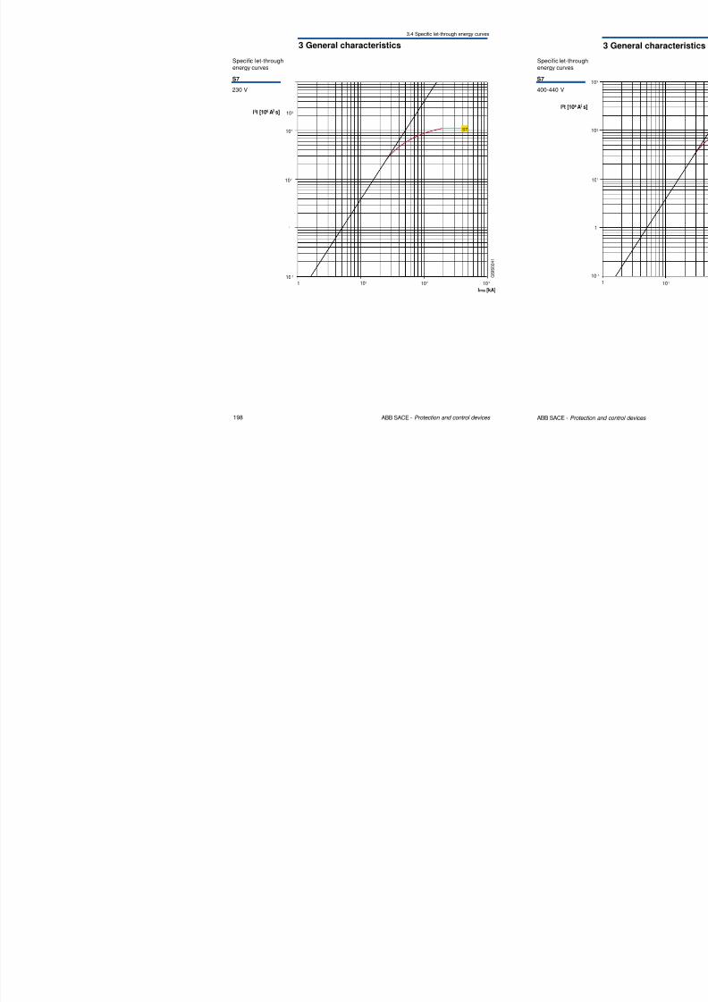
103I2t [10 A s]6 2
S7
230 V
Specific let-throughenergy curves
8/3/2019 ABB Electrical Install Ti On Handbook 4th Edition
http://slidepdf.com/reader/full/abb-electrical-install-ti-on-handbook-4th-edition 102/322
198 ABB SACE - Protection and control devices
G S I S 0 2 4 1
1
1
10
102
101
10 -1
101 102
Irms [kA]
103
I t [10 A s]
S7
3 General characteristics
3.4 Specific let-through energy curves
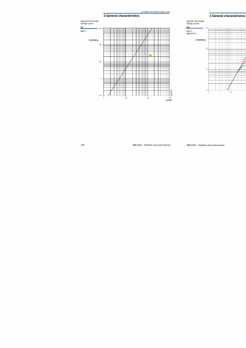
103
I2t [10 A s]6 2
S7
690 V
Specific let-throughenergy curves

8/3/2019 ABB Electrical Install Ti On Handbook 4th Edition
http://slidepdf.com/reader/full/abb-electrical-install-ti-on-handbook-4th-edition 103/322
200 ABB SACE - Protection and control devices
G S I S 0 2 5 3
1
S7
1
103
102
101
10 -1
101 102
Irms [kA]
I2t [10 A s]6 2
3 General characteristics
3.4 Specific let-through energy curves
103E2L
690 V~
380/415 V~
Specific let-throughenergy curves
8/3/2019 ABB Electrical Install Ti On Handbook 4th Edition
http://slidepdf.com/reader/full/abb-electrical-install-ti-on-handbook-4th-edition 104/322
202 ABB SACE - Protection and control devices
101
1
102
1Irms kA
10101 102
I2t [10 A s]6 2
380/415 V
690 V
1 S D C 2 0 0 0 9 3 F 0 0 0 1
8/3/2019 ABB Electrical Install Ti On Handbook 4th Edition
http://slidepdf.com/reader/full/abb-electrical-install-ti-on-handbook-4th-edition 105/322
8/3/2019 ABB Electrical Install Ti On Handbook 4th Edition
http://slidepdf.com/reader/full/abb-electrical-install-ti-on-handbook-4th-edition 106/322
8/3/2019 ABB Electrical Install Ti On Handbook 4th Edition
http://slidepdf.com/reader/full/abb-electrical-install-ti-on-handbook-4th-edition 107/322
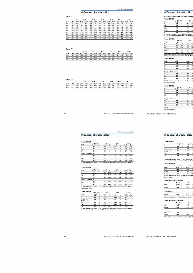
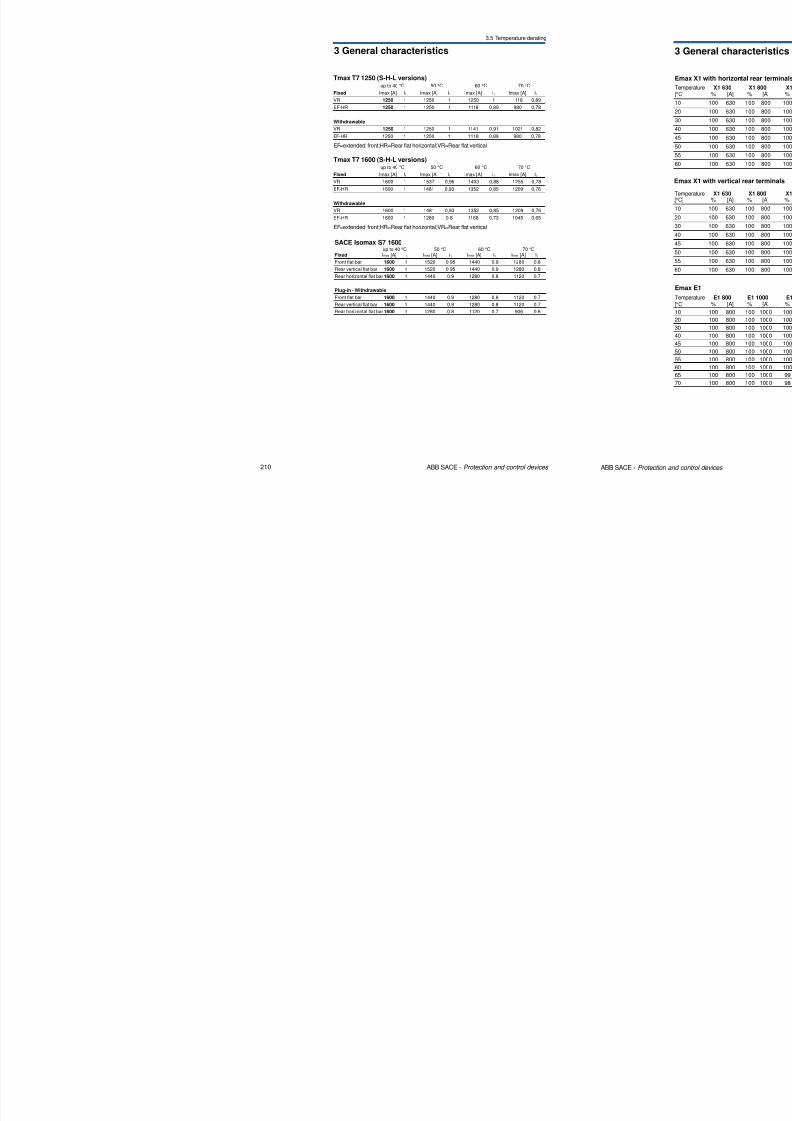
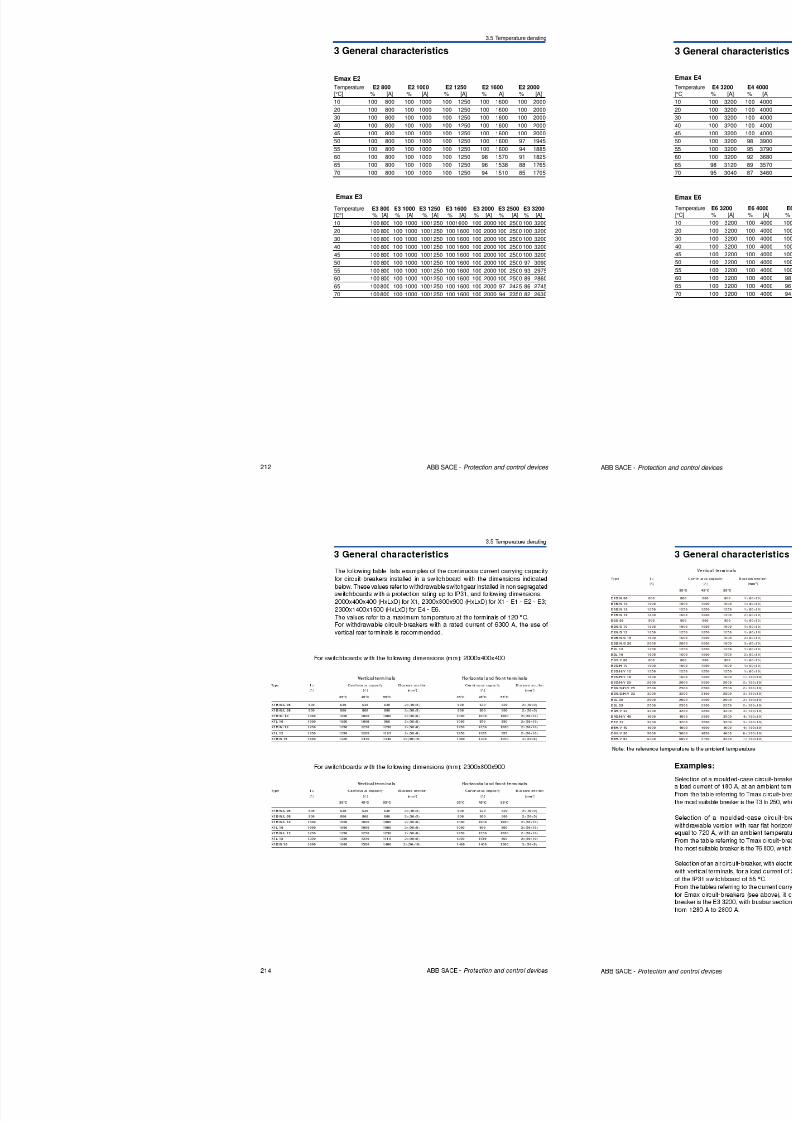
3 General characteristics
3.5 Temperature derating
Tmax T7 1250 (S-H-L versions)up to 40 °C 50 °C 60 °C 70 °C
Fixed Imax [A] I1 Imax [A] I1 Imax [A] I1 Imax [A] I1
VR 1250 1 1250 1 1250 1 1118 0,89
EF-HR 1250 1 1250 1 1118 0,89 980 0,78
Withdrawable
VR 1250 1 1250 1 1141 0,91 1021 0,82
EF HR 1250 1 1250 1 1118 0 89 980 0 78

8/3/2019 ABB Electrical Install Ti On Handbook 4th Edition
http://slidepdf.com/reader/full/abb-electrical-install-ti-on-handbook-4th-edition 108/322
210 ABB SACE - Protection and control devices
SACE Isomax S7 1600up to 40 °C 50 °C 60 °C 70 °C
Fixed Imax [A] I1 Imax [A] I1 Imax [A] I1 Imax [A] I1
Front flat bar 1600 1 1520 0.95 1440 0.9 1280 0.8
Rear vertical flat bar 1600 1 1520 0.95 1440 0.9 1280 0.8
Rear horizontal flat bar 1600 1 1440 0.9 1280 0.8 1120 0.7
Plug-in - Withdrawable
Front flat bar 1600 1 1440 0.9 1280 0.8 1120 0.7
Rear vertical flat bar 1600 1 1440 0.9 1280 0.8 1120 0.7
Rear horizontal flat bar 1600 1 1280 0.8 1120 0.7 906 0.6
EF-HR 1250 1 1250 1 1118 0,89 980 0,78
EF=extended front;HR=Rear flat horizontal;VR=Rear flat vertical
Tmax T7 1600 (S-H-L versions)up to 40 °C 50 °C 60 °C 70 °C
Fixed Imax [A] I1 Imax [A] I1 Imax [A] I1 Imax [A] I1
VR 1600 1 1537 0,96 1403 0,88 1255 0,78
EF-HR 1600 1 1481 0,93 1352 0,85 1209 0,76
Withdrawable
VR 1600 1 1481 0,93 1352 0,85 1209 0,76
EF-HR 1600 1 1280 0,8 1168 0,73 1045 0,65
EF=extended front;HR=Rear flat horizontal;VR=Rear flat vertical
3 General characteristics
3.5 Temperature derating
Emax E2
Temperature E2 800 E2 1000 E2 1250 E2 1600 E2 2000[°C] % [A] % [A] % [A] % A] % [A]
10 100 800 100 1000 100 1250 100 1600 100 2000
20 100 800 100 1000 100 1250 100 1600 100 200030 100 800 100 1000 100 1250 100 1600 100 2000
40 100 800 100 1000 100 1250 100 1600 100 2000
45 100 800 100 1000 100 1250 100 1600 100 2000
8/3/2019 ABB Electrical Install Ti On Handbook 4th Edition
http://slidepdf.com/reader/full/abb-electrical-install-ti-on-handbook-4th-edition 109/322
212 ABB SACE - Protection and control devices
Emax E3
50 100 800 100 1000 100 1250 100 1600 97 1945
55 100 800 100 1000 100 1250 100 1600 94 1885
60 100 800 100 1000 100 1250 98 1570 91 1825
65 100 800 100 1000 100 1250 96 1538 88 1765
70 100 800 100 1000 100 1250 94 1510 85 1705
Temperature E3 800 E3 1000 E3 1250 E3 1600 E3 2000 E3 2500 E3 3200[C°] % [A] % [A] % [A] % [A] % [A] % [A] % [A]
10 100 800 100 1000 1001250 1001600 100 2000 100 2500 100 3200
20 100 800 100 1000 1001250 100 1600 100 2000 100 2500 100 3200
30 100 800 100 1000 1001250 100 1600 100 2000 100 2500 100 3200
40 100 800 100 1000 1001250 100 1600 100 2000 100 2500 100 3200
45 100 800 100 1000 1001250 100 1600 100 2000 100 2500 100 3200
50 100 800 100 1000 1001250 100 1600 100 2000 100 2500 97 3090
55 100 800 100 1000 1001250 100 1600 100 2000 100 2500 93 2975
60 100 800 100 1000 1001250 100 1600 100 2000 100 2500 89 2860
65 100800 100 1000 1001250 100 1600 100 2000 97 2425 86 274570 100800 100 1000 1001250 100 1600 100 2000 94 2350 82 2630
8/3/2019 ABB Electrical Install Ti On Handbook 4th Edition
http://slidepdf.com/reader/full/abb-electrical-install-ti-on-handbook-4th-edition 110/322
3 General characteristics
3.5 Temperature derating
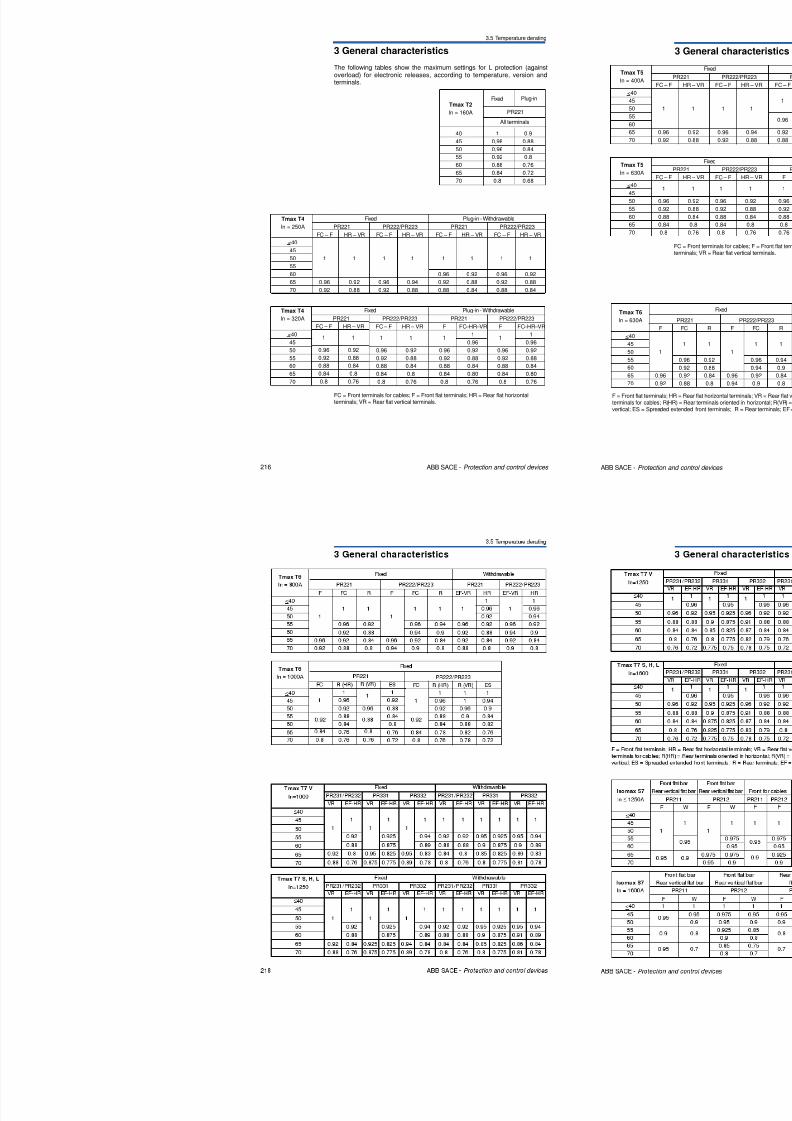
40 1 0.9
The following tables show the maximum settings for L protection (againstoverload) for electronic releases, according to temperature, version andterminals.
All terminals
PR221
Fixed Plug-inTmax T2
In = 160A
8/3/2019 ABB Electrical Install Ti On Handbook 4th Edition
http://slidepdf.com/reader/full/abb-electrical-install-ti-on-handbook-4th-edition 111/322
216 ABB SACE - Protection and control devices
45 0.98 0.88
50 0.96 0.84
55 0.92 0.8
60 0.88 0.76
65 0.84 0.72
70 0.8 0.68
Tmax T4
In = 250A
<40
45
50
55
60
65
70
PR221
FC – F HR – VR
1 1
0.96 0.92
0.92 0.88
Fixed
PR222/PR223
FC – F HR – VR
1 1
0.96 0.94
0.92 0.88
PR221
FC – F HR – VR
1 1
0.96 0.92
0.92 0.88
0.88 0.84
Plug-in - Withdrawable
PR222/PR223
FC – F HR – VR
1 1
0.96 0.92
0.92 0.88
0.88 0.84
FC = Front terminals for cables; F = Front flat terminals; HR = Rear flat horizontalterminals; VR = Rear flat vertical terminals.
Tmax T4
In = 320A
<40
45
50
55
60
65
70
PR221
FC – F HR – VR
1 1
0.96 0.92
0.92 0.88
0.88 0.84
0.84 0.8
0.8 0.76
Fixed
PR222/PR223
FC – F HR – VR
1 1
0.96 0.92
0.92 0.88
0.88 0.84
0.84 0.8
0.8 0.76
PR221
F FC – HR – VR
11
0.96
0.96 0.92
0.92 0.88
0.88 0.84
0.84 0.80
0.8 0.76
Plug-in - Withdrawable
PR222/PR223
F FC – HR – VR
11
0.96
0.96 0.92
0.92 0.88
0.88 0.84
0.84 0.80
0.8 0.76
8/3/2019 ABB Electrical Install Ti On Handbook 4th Edition
http://slidepdf.com/reader/full/abb-electrical-install-ti-on-handbook-4th-edition 112/322
3 General characteristics
3.5 Temperature derating
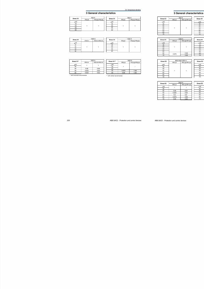
Emax X1
<40
45
50
55
60
630 A
PR331 PR332/PR333
1 1
Emax X1
<40
45
50
55
60
800 A
PR331 PR332/PR333
1 1
8/3/2019 ABB Electrical Install Ti On Handbook 4th Edition
http://slidepdf.com/reader/full/abb-electrical-install-ti-on-handbook-4th-edition 113/322
220 ABB SACE - Protection and control devices
Emax X1
<40
45
50
55
60
1000 A
PR331 PR332/PR333
1 1
Emax X1*
<40
45
50
55
60
1600 A
PR331 PR332/PR333
1 1
0.95 0.96
0.925 0.93
0.925 0.92
Emax X1
<40
45
50
55
60
1250 A
PR331 PR332/PR333
1 1
Emax X1**
<40
45
50
55
60
1600 A
PR331 PR332/PR333
1 1
0.975 0.98
0.95 0.95
** with vertical rear termainals* with horizontal rear termainals
3 General characteristics
3.5 Temperature derating
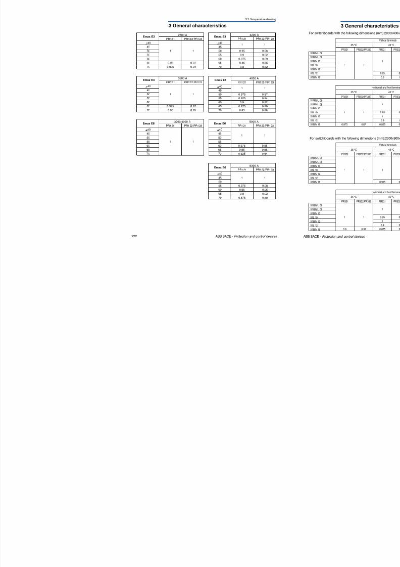
Emax E3
<40
45
50
55
60
65
70
2500 A
PR121 PR122/PR123
1 1
0.95 0.97
0.925 0.94
Emax E3
<40
45
50
55
60
65
70
3200 A
PR121 PR122/PR123
1 1
0.95 0.96
0.9 0.92
0.875 0.89
0.85 0.85
0.8 0.82
8/3/2019 ABB Electrical Install Ti On Handbook 4th Edition
http://slidepdf.com/reader/full/abb-electrical-install-ti-on-handbook-4th-edition 114/322
222 ABB SACE - Protection and control devices
Emax E6
<40
45
50
55
6065
70
3200/4000 A
PR121 PR122/PR123
1 1
Emax E6
<40
45
50
55
6065
70
5000 A
PR121 PR122/PR123
1 1
0.975 0.980.95 0.96
0.925 0.94
Emax E6
<40
45
50
55
60
65
70
6300 A
PR121 PR122/PR123
1 1
0.975 0.98
0.95 0.96
0.9 0.92
0.875 0.88
Emax E4
<40
45
50
55
6065
70
3200 A
PR121 PR122/PR123
1 1
0.975 0.97
0.95 0.95
Emax E4
<40
45
50
55
6065
70
4000 A
PR121 PR122/PR123
1 1
0.975 0.97
0.925 0.94
0.9 0.920.875 0.89
0.85 0.86
3 General characteristics
3.5 Temperature derating
PR121 PR122/PR123
1 1
1 1
1 1
1 11 1
1 1
1 1
1 1
1 1
PR121 PR122/PR123
1 1
1 1
1 1
1 11 1
1 1
1 1
1 1
1 1
PR121 PR122/ PR123
1 1
1 1
1 1
0.925 0.931 1
1 1
1 1
1 1
0 9 0 9
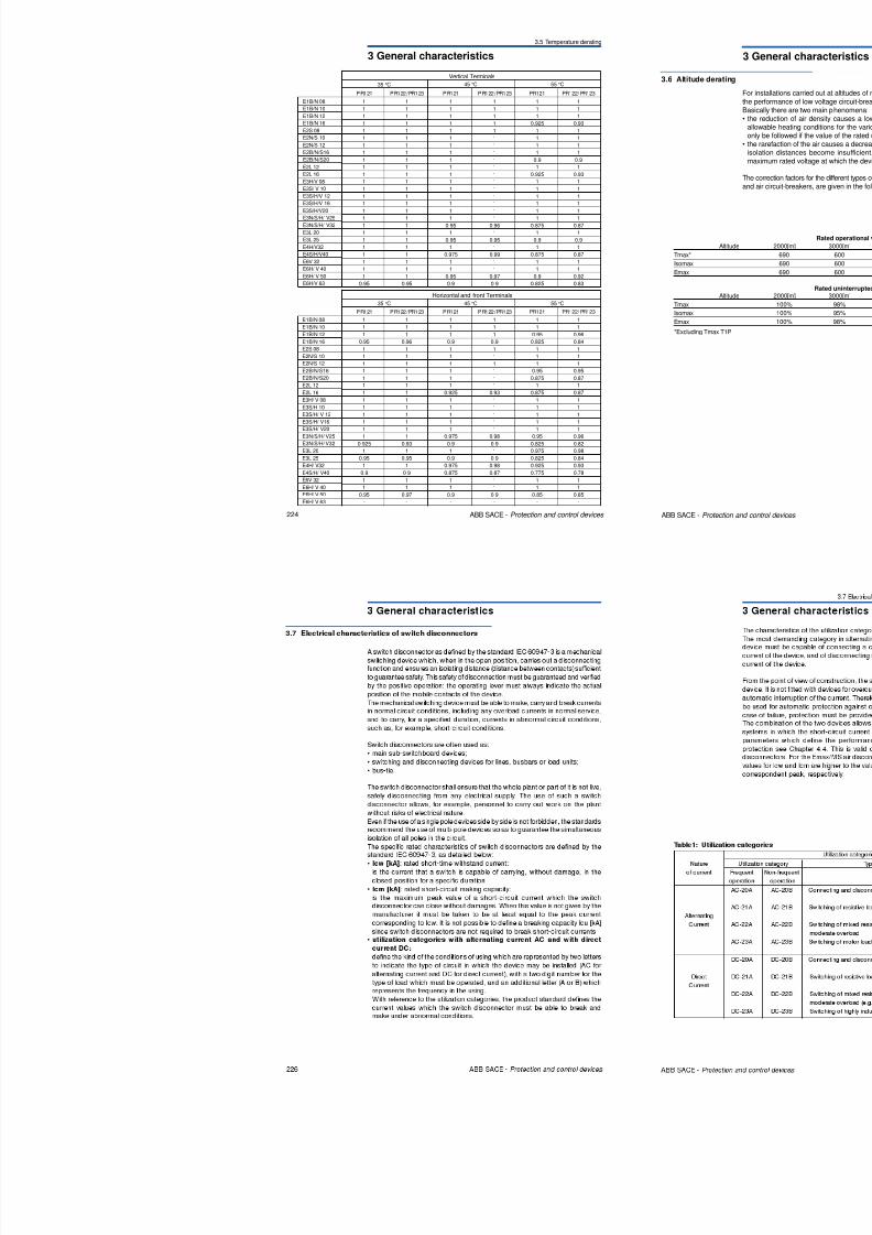
35 °C 45 °C 55 °C
Vertical Terminals
E1B/N 08
E1B/N 10
E1B/N 12
E1B/N 16E2S 08
E2N/S 10
E2N/S 12
E2B/N/S16
E2B/N/S20

8/3/2019 ABB Electrical Install Ti On Handbook 4th Edition
http://slidepdf.com/reader/full/abb-electrical-install-ti-on-handbook-4th-edition 115/322
224 ABB SACE - Protection and control devices
PR121 PR122/PR123
1 11 1
1 1
0.95 0.96
1 1
1 1
1 1
1 1
1 1
1 1
1 1
1 1
1 1
1 11 1
1 1
1 1
0.925 0.93
1 1
0.95 0.95
1 1
0.9 0.9
1 1
1 1
0.95 0.97
- -
PR121 PR122/PR123
1 11 1
1 1
0.9 0.9
1 1
1 1
1 1
1 1
1 1
1 1
0.925 0.93
1 1
1 1
1 11 1
1 1
0.975 0.98
0.9 0.9
1 1
0.9 0.9
0.975 0.98
0.875 0.87
1 1
1 1
0.9 0.9
- -
PR121 PR122/ PR123
1 11 1
0.95 0.96
0.825 0.84
1 1
1 1
1 1
0.95 0.95
0.875 0.87
1 1
0.875 0.87
1 1
1 1
1 11 1
1 1
0.95 0.96
0.825 0.82
0.975 0.98
0.825 0.84
0.925 0.93
0.775 0.78
1 1
1 1
0.85 0.85
- -
35 °C 45 °C 55 °C
Horizontal and front Terminals
1 1
1 1
1 1
1 1
1 1
1 1
1 1
1 1
1 1
1 1
1 1
1 1
1 1
1 1
1 1
1 1
1 1
0.95 0.95
1 1
1 1
1 1
1 1
1 1
1 1
1 1
1 1
1 1
0.95 0.96
1 1
0.95 0.95
1 1
0.975 0.99
1 1
1 1
0.95 0.97
0.9 0.9
0.9 0.9
1 1
0.925 0.93
1 1
1 1
1 1
1 1
1 1
1 1
0.875 0.87
1 1
0.9 0.9
1 1
0.875 0.87
1 1
1 1
0.9 0.92
0.825 0.83
E2B/N/S20
E2L 12
E2L 16
E3H/V 08
E3S/ V 10
E3S/H/V 12
E3S/H/V 16
E3S/H/V20
E3N/S/H/ V25
E3N/S/H/ V32
E3L 20
E3L 25
E4H/V32
E4S/H/V40
E6V 32
E6H/ V 40
E6H/ V 50
E6H/V 63
E1B/N 08E1B/N 10
E1B/N 12
E1B/N 16
E2S 08
E2N/S 10
E2N/S 12
E2B/N/S16
E2B/N/S20
E2L 12
E2L 16
E3H/ V 08
E3S/H 10
E3S/H/ V 12E3S/H/ V16
E3S/H/ V20
E3N/S/H/ V25
E3N/S/H/ V32
E3L 20
E3L 25
E4H/ V32
E4S/H/ V40
E6V 32
E6H/ V 40
E6H/ V 50
E6H/ V 63

8/3/2019 ABB Electrical Install Ti On Handbook 4th Edition
http://slidepdf.com/reader/full/abb-electrical-install-ti-on-handbook-4th-edition 116/322
3 General characteristics
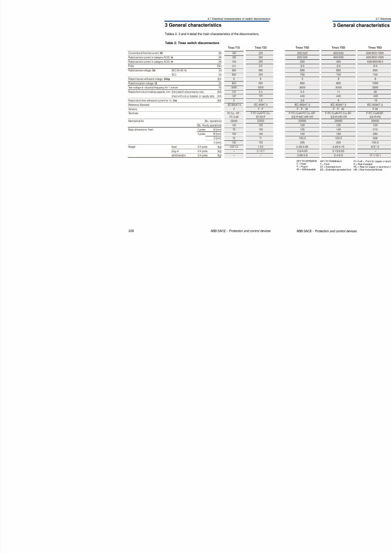
3.7 Electrical characteristics of switch disconnectors
Table 2: Tmax switch disconnectors
Tables 2, 3 and 4 detail the main characteristics of the disconnectors.
Tmax T1D
Conventional thermal current, Ith [A] 160
Rated service current in category AC22, Ie [A] 160
Rated service current in category AC23, Ie [A] 125
Poles [Nr.] 3/4
Rated service voltage, Ue (AC) 50-60 Hz [V] 690
Tmax T3D
250
250
200
3/4
690
8/3/2019 ABB Electrical Install Ti On Handbook 4th Edition
http://slidepdf.com/reader/full/abb-electrical-install-ti-on-handbook-4th-edition 117/322
228 ABB SACE - Protection and control devices
(DC) [V] 500
Rated impulse withstand voltage, Uimp [kV] 8
Rated insulation voltage, Ui [V] 800
Test voltage at industrial frequency for 1 minute [V] 3000
Rated short-circuit making capacity, Icm (min) switch-disconnector only [kA] 2.8
(max) w ith c ircuit -breaker on supply side [kA] 187
Rated short-time withstand current for 1s, Icw [kA] 2
Reference Standard IEC 60947-3
Versions F
Terminals FC Cu - EF -
FC CuAl
Mechanical life [No. operations] 25000
[No. Hourly operations] 120
Basic dimensions, fixed 3 poles W [mm] 76
4 poles W [mm] 102
D [mm] 70
H [mm] 130Weight fixed 3/4 poles [kg] 0.9/1.2
plug-in 3/4 poles [kg] –
withdrawable 3/4 poles [kg] –
500
8
800
3000
5.3
105
3.6IEC 60947-3
F - P
F-FC CuAl-FC Cu-
EF-ES-R
25000
120
105
140
70
1501.5/2
2.1/3.7
–
3 General characteristics
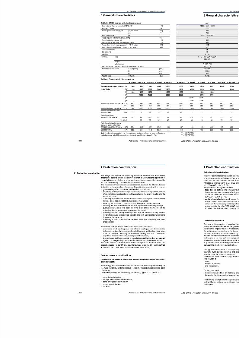
3.7 Electrical characteristics of switch disconnectors
Conventional thermal current at 40 °C, Ith [A]
Number of poles Nr.
Rated operational voltage, Ue (ac) 50-60Hz [V~]
(dc) [V – ]
Rated current, Ie [A]
Rated impulse withstand voltage, Uimp [kV]
Rated insulation voltage, Ui [V]
Test voltage at industrial frequency for 1 min. [V]
R t d h t i it ki it (415 V ) I [kA]
Table 3: SACE Isomax switch disconnectors
8/3/2019 ABB Electrical Install Ti On Handbook 4th Edition
http://slidepdf.com/reader/full/abb-electrical-install-ti-on-handbook-4th-edition 118/322
230 ABB SACE - Protection and control devices
X1B/MS E1B/MS E1N/MS E2B/MS E2N/MS
Rated uninterrupted current [A] 1000 800 800 1600 1000
(a 40 °C) Iw [A] 1250 1000 1000 2000 1250
[A] 1600 1250 1250 1600
[A] 1600 1600 2000
[A]
[A]
Rated operational voltage Ue [V ~] 690 690 690 690 690
[V –] 250 250 250 250 250
Rated insulation voltage Ui [V ~] 1000 1000 1000 1000 1000Rated impulse withstandvoltage Uimp [kV] 12 12 12 12 12
Rated short-time
withstand current Icw (1s) [kA] 42 42 50(1) 42 55
(3s) [kA] 36 36 42 42
Rated short-circuit makingcapacity (peak value) Icm220/230/380/400/415/440 V ~ [kA] 88.2 88.2 105 88.2 143
500/660/690 V ~ [kA] 88.2 5.6 75.6 88.2 121
Table 4: Emax switch disconnectors
Rated short-circuit making capacity (415 V~), Icm [kA]
Rated short-time withstand current for 1 s, Icw [kA]
Isolation behaviour
IEC 60947-3
Versions
Terminals fixed
plug-in
withdrawable
Mechanical life [No. of operations / operation per hour]
Basic dimensions, fixed L (3/4 poles) [mm]
D [mm]
H [mm]
Weight, fixed 3/4 poles [kg]
Note: the breaking capacity Icu
, at the maximum rated use voltage, by means of externalprotection relay, with 500 ms maximum timing, is equal to the value of I
cw(1s).

8/3/2019 ABB Electrical Install Ti On Handbook 4th Edition
http://slidepdf.com/reader/full/abb-electrical-install-ti-on-handbook-4th-edition 119/322
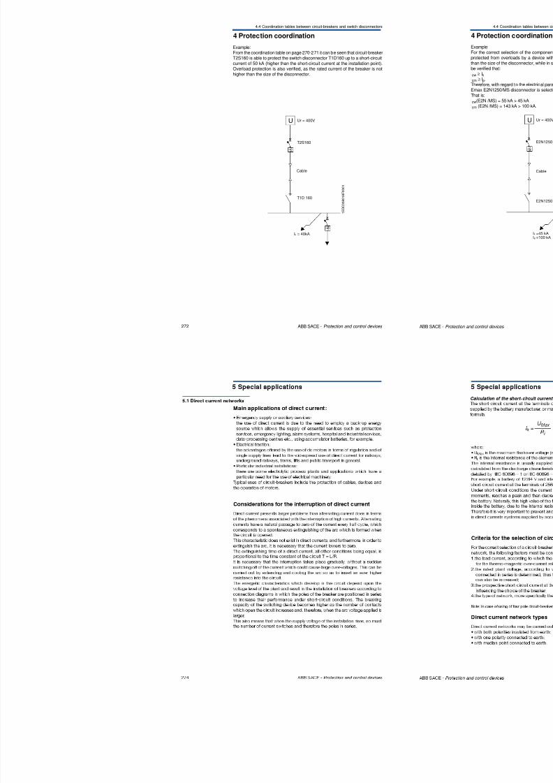
8/3/2019 ABB Electrical Install Ti On Handbook 4th Edition
http://slidepdf.com/reader/full/abb-electrical-install-ti-on-handbook-4th-edition 120/322
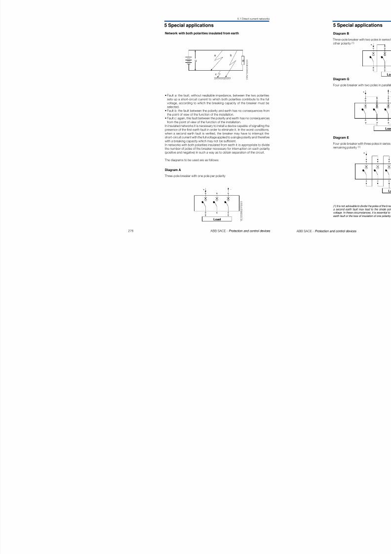
8/3/2019 ABB Electrical Install Ti On Handbook 4th Edition
http://slidepdf.com/reader/full/abb-electrical-install-ti-on-handbook-4th-edition 121/322
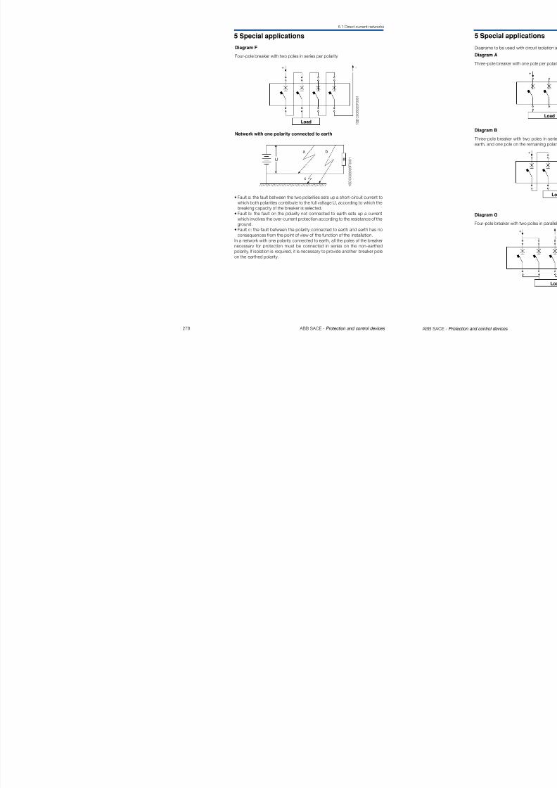
8/3/2019 ABB Electrical Install Ti On Handbook 4th Edition
http://slidepdf.com/reader/full/abb-electrical-install-ti-on-handbook-4th-edition 122/322
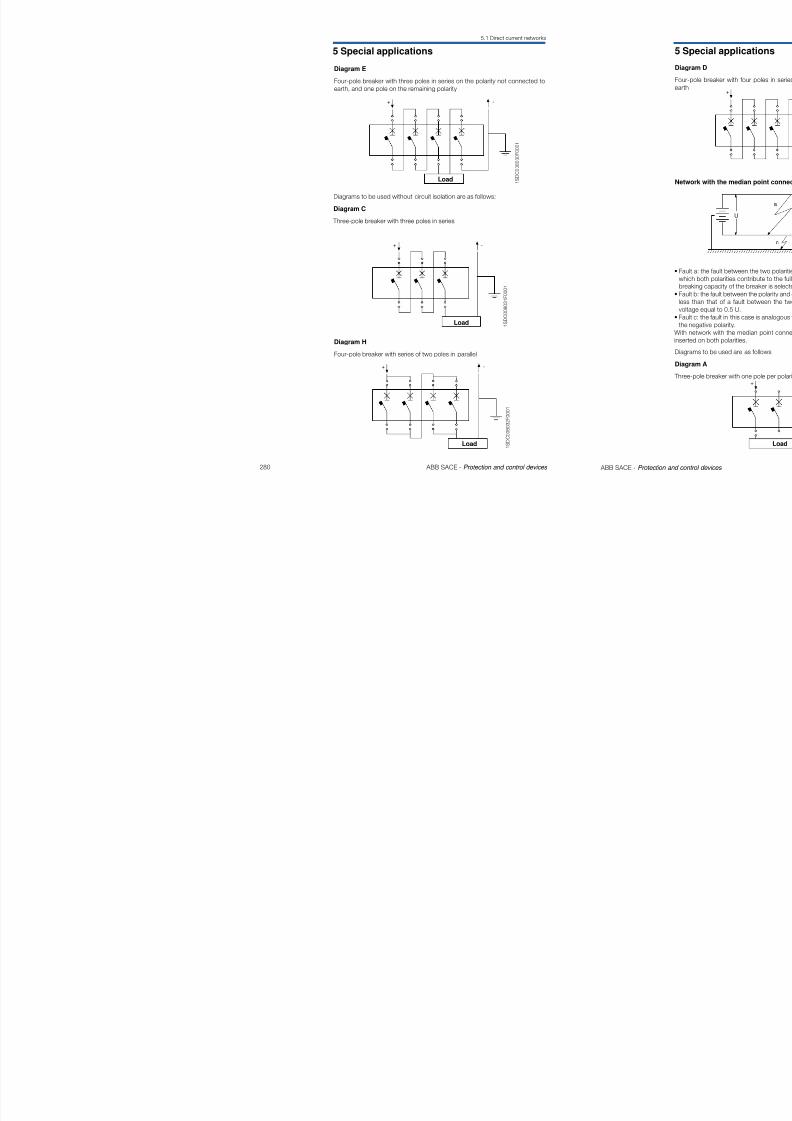
8/3/2019 ABB Electrical Install Ti On Handbook 4th Edition
http://slidepdf.com/reader/full/abb-electrical-install-ti-on-handbook-4th-edition 123/322
4 Protection coordination
4.2 Discrimination tables
104
U Ur = 400V
t [s]
Example:
From the selectivity table on page 265 it can be seen that breakers E2N1250and T5H400,correctly set, are selective up to 55kA (higher than the short-circuitcurrent at the busbar).From the selectivity table on page 258 it can be seen that, between T5H400
and T1N160 In125, the total sectivity is granted; as aleady specified on page241 this means selectivity up to the breaking capacity of T1N and therefore upto 36 kA (higher than the short-circuit current at the busbar).
Time-current curves

8/3/2019 ABB Electrical Install Ti On Handbook 4th Edition
http://slidepdf.com/reader/full/abb-electrical-install-ti-on-handbook-4th-edition 124/322
242 ABB SACE - Protection and control devices
22kA 50kA
E2N1250 In1250
T5H400 In400
T1N160 In125
Ik=22kA
T1N160 In125
U
E2N 1250 In1250
Ik=50kA
T5H400
103
102
101
1
10-1
10-2
10-1 1 101 I [kA]
1 S D C 0 0 8 0 1 6 F 0 0 0 1
Cable
Cable
From the curves it is evident that between breakers E2N1250 and T5H400time discrimination exists, while between breakers T5H400 and T1N160 thereis energy discrimination.
4 Protection coordination
4.2 Discrimination tables
Discrimination tables M CB-MCB
MCB - S2.. D @ 415V
S290 S500
D
80
T
T
100
T
T
32
T
3
40
T
6
50
T
T
63
T
T
15 50
In [A]
≤2
3
6
-
-
10
S200
S200
15
S200M
S200M
25
S200P
S200P
Icu [kA]
Char.
Supply s.
D
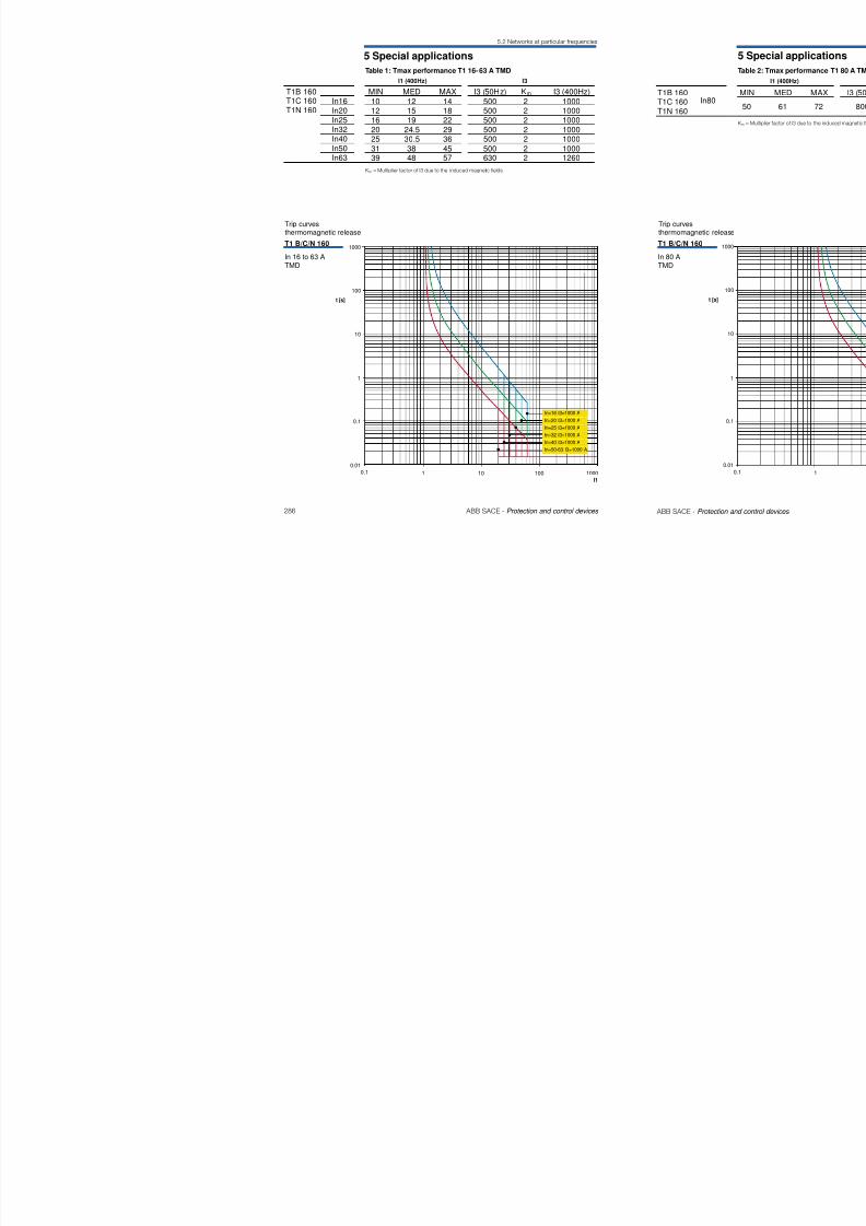
8/3/2019 ABB Electrical Install Ti On Handbook 4th Edition
http://slidepdf.com/reader/full/abb-electrical-install-ti-on-handbook-4th-edition 125/322
244 ABB SACE - Protection and control devices
T
10.5
10.5
5
3
33
T
T
T
8
5
55
4
2
1.5
1.5
1
3
2
2
1.5
6
3
3
2
1.5
T
5.5
5.5
3
2
2
4
6
8
10
13
16
20
25
32
40
50
63
-
-
-
-
-
--
-
-
-
-
-
S200
S200
S200
S200
S200
S200S200
S200
S200
S200
S200
S200
S200M
S200M
S200M
S200M
-
S200MS200M
S200M
S200M-S200P
S200M-S200P
S200M-S200P
S200M-S200P
S200P
S200P
S200P
S200P
S200P
S200PS200P
S200P
-
-
-
-
L
o a d
s .
D
S290 S500
D
80
T
T
T
10.5
10.5
5
3
3
3
100
T
T
T
T
T
8
5
5
5
4
32
T
3
2
1.5
1.5
40
T
6
3
2
2
1.5
50
T
T
6
3
3
2
1.5
63
T
T
T
5.5
5.5
3
2
2
15 50
In [A]
≤2
3
4
6
8
10
13
16
20
25
32
40
50
63
6
-
-
-
-
-
-
-
-
-
-
-
-
-
-
10
S200
S200
S200
S200
S200
S200
-
S200
S200
S200
S200
S200
S200
S200
15
S200M
S200M
S200M
S200M
S200M
S200M
-
S200M
S200M
S200M
S200M-S200P
S200M-S200P
S200M-S200P
S200M-S200P
25
S200P
S200P
S200P
S200P
S200P
S200P
S200P
S200P
S200P
S200P
-
-
-
-
Icu [kA]
Char.
L o a d
s .
Supply s.
D
K
MCB - S2.. K @ 415V
4 Protection coordination
4.2 Discrimination tables
MCB/MCCB - S500 @ 415V
T1-T2-T3
In [A]
6
10
13
Icu [kA]Char.Load s.
Supply s.
Version
Release
40
5.5
4.5
4.5
63
10.5
8
7.5
16
5.5
12.5
4.5
TM
T2 T1-T2
B, C, N, S, H, L, V
S290 D
80
6
6
6
100
10
10
10
25
5.5
4.5
32
5.5
4.5
4.5
50
5.5
4.5
4.5
80
15
10
10
100
20
20
15
20
5.5
4.5 (1)
4.5 (1)
Discrimination tables MCB/ MCCB - S500
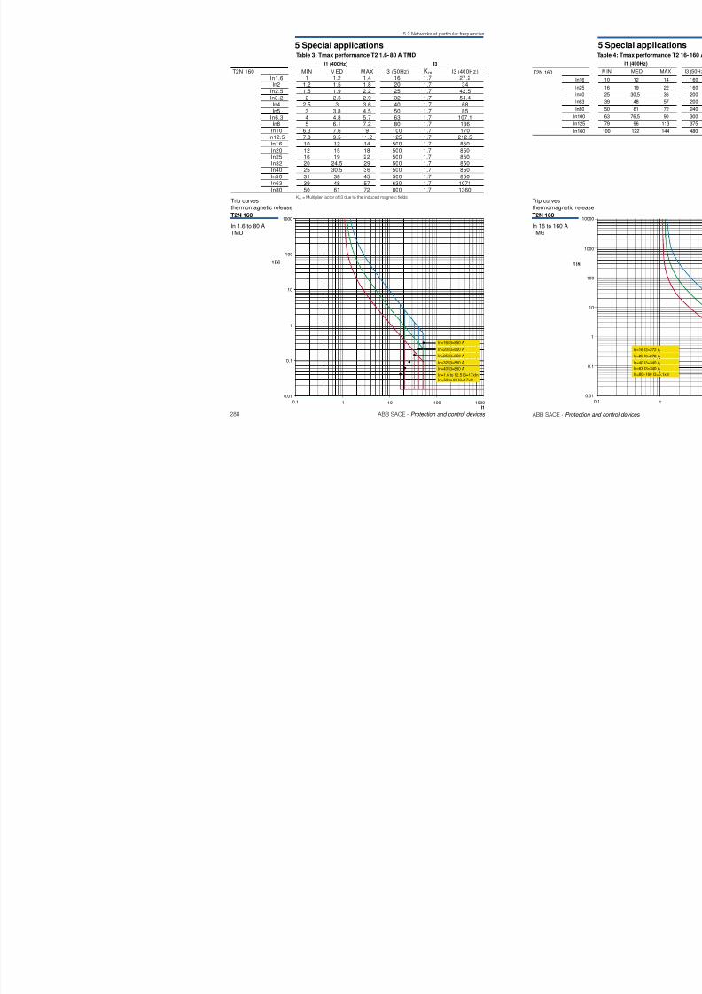
8/3/2019 ABB Electrical Install Ti On Handbook 4th Edition
http://slidepdf.com/reader/full/abb-electrical-install-ti-on-handbook-4th-edition 126/322
246 ABB SACE - Protection and control devices
16
20
25
32
40
50
63
6
10
13
16
20
25
32
40
5063
≤5.8
5.3…8
7.3…11
10…15
14…20
18…26
23…32
29…37
34…41
38…45
B, C
4.5 7.5
7.5
6
S500
50
K
50
30
36
5.5
4.5 (1)
4.5 (1)
36
5.5
36
4.5 (1)
36
5.5
4.5
36
5.5
4.5
4.5
4.5 (1)
4.5 (1)
36
5.5
4.5
4.5
4.5
36
5.5
4.5
4.5
4.5
4.5
4.5 (1)
4.5 (1)
36
10.5
8
7.5
7.5
7.5
6
36
36
36
10
10
10
10
7.5
5(1)
5(1)
36
36
36
15
15
15
15
10
10
7.5 (2)
6
6
4.5
10
7.5
6
6
T
10
7.5
4.5
4.5
T
T
T
10
6
4.5
(1) Value for the supply side magnetic o nly T2 circuit-breaker.(2) Value for the supply side magnetic o nly T2-T3 circuit-breaker.(3) Value for the supply side magnetic o nly T3 circuit-breaker.(4) Value for the supply side magnetic o nly T4 circuit-breaker.
4.5 (1)
4.5 (1)
4.5
4.5
4.5 (1)
4.5 (1)
10
10
10
7.5
5 (1)
5 (1)
15
15
15
10
10
7.5 (2)
5(2)
D 50
5.5
4.5 (1)
4.5 (1)
5.5
4.5
5.5
4.5
4.5
4.5 (1)
4.5 (1)
5.5
4.5
4.5
4.5
5.5
4.5
4.5
4.5
4.5
4.5 (1)
4.5 (1)
10.5
8
7.5
7.5
7.5
6
15
10
10
10
10
10
7.5
5(1)
5(1)
20
20
15
15
15
15
10
10
7.5(2)
5(2)
5.54.56
6
6
6
6
4.5
10
10
10
10
7.5
6
6
4 Protection coordination
4.2 Discrimination tables
MCCB - S2.. B @ 415V
In [A]
≤2
3
4
Icu [kA]Char. Supply s.
Version
Release
20 25 40 50 631612.5
TM
T2 T1-T2
B, C, N, S, H, L
326
-
-
10
-
-
15
-
-
25
-
-
Discrimination tables MCCB - S2..
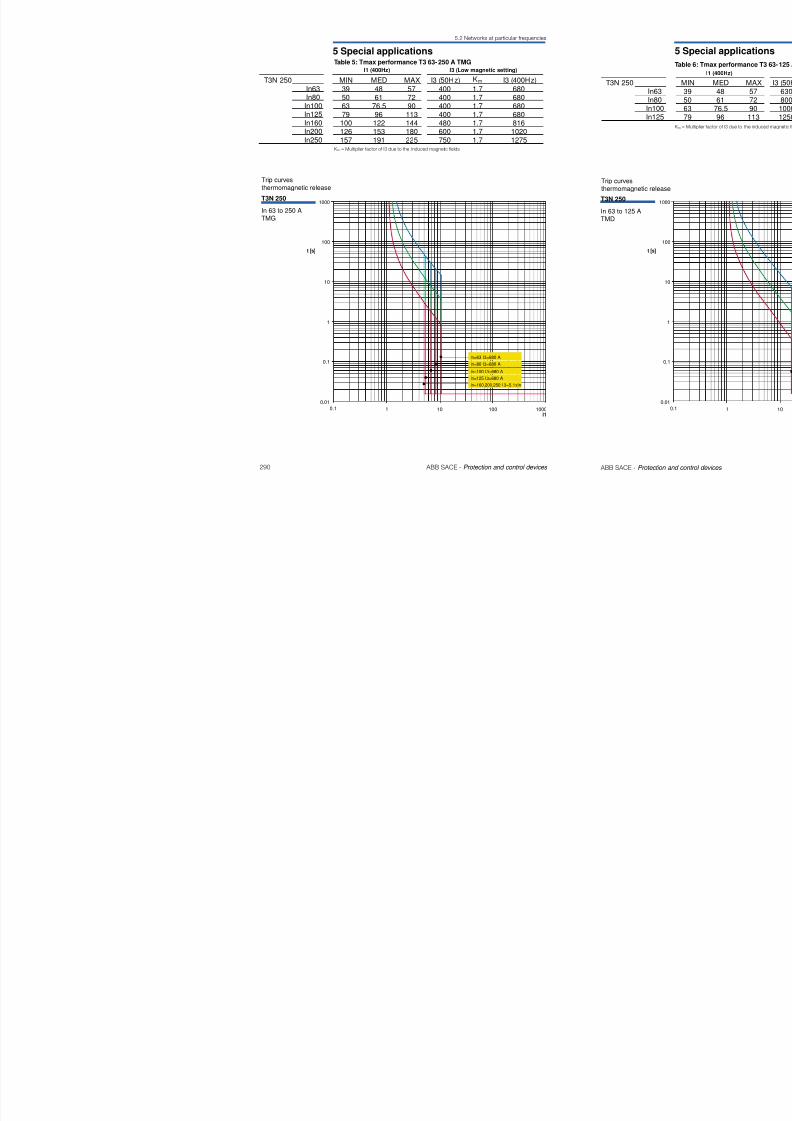
8/3/2019 ABB Electrical Install Ti On Handbook 4th Edition
http://slidepdf.com/reader/full/abb-electrical-install-ti-on-handbook-4th-edition 127/322
248 ABB SACE - Protection and control devices
4
6
8
10
13
1620
25
32
40
50
63
80
100
125
L o a d
s .
B
5.5
5.5
3(1)
3(1)
5.5
5.5
3
5.5
5.5
3
3
3
5.5
5.5
4.5
4.5
4.53
3(1)
3(1)
10.5
10.5
7.5
7.5
55
5
5.55.5 (1)
(1) Value for the supply side magnetic only T2 circuit-breaker.(2) Value for the supply side magnetic only T2-T3 circuit-breaker.(3) Value for the supply side magnetic only T3 circuit-b reaker.(4) Value for the supply side magnetic only T4 circuit-b reaker.
5.5
5.5
3
3
3(1)
3(1)
-
-
-
-
-
-
-
-
-
-
-
-
-
-
-
-
S200
S200
S200
S200
S200
S200
S200
S200
S200
S200
S200
-
-
-
-
S200M
S200M
S200M
S200M
S200M
S200M
S200M
S200M-S200P
S200M-S200P
S200M-S200P
S200M-S200P
-
-
-
-
S200P
S200P
S200P
S200P
S200P
S200P
S200P
-
-
-
-
-
-
-
4 Protection coordination
4.2 Discrimination tables
MCCB - S2.. C @ 415V
In [A]
≤2
3
Icu [kA]Char. Supply s.
Version
Release
20
T
T
25
T
T
32
T
T
40
T
T
50
T
T
63
T
T
16
T
T
12.5
T
T
TM
T2 T1-T2
B, C, N, S, H, L
6
-
-
10
S200
S200
15
S200M
S200M
25
S200P
S200P
Discrimination tables MCCB - S2..
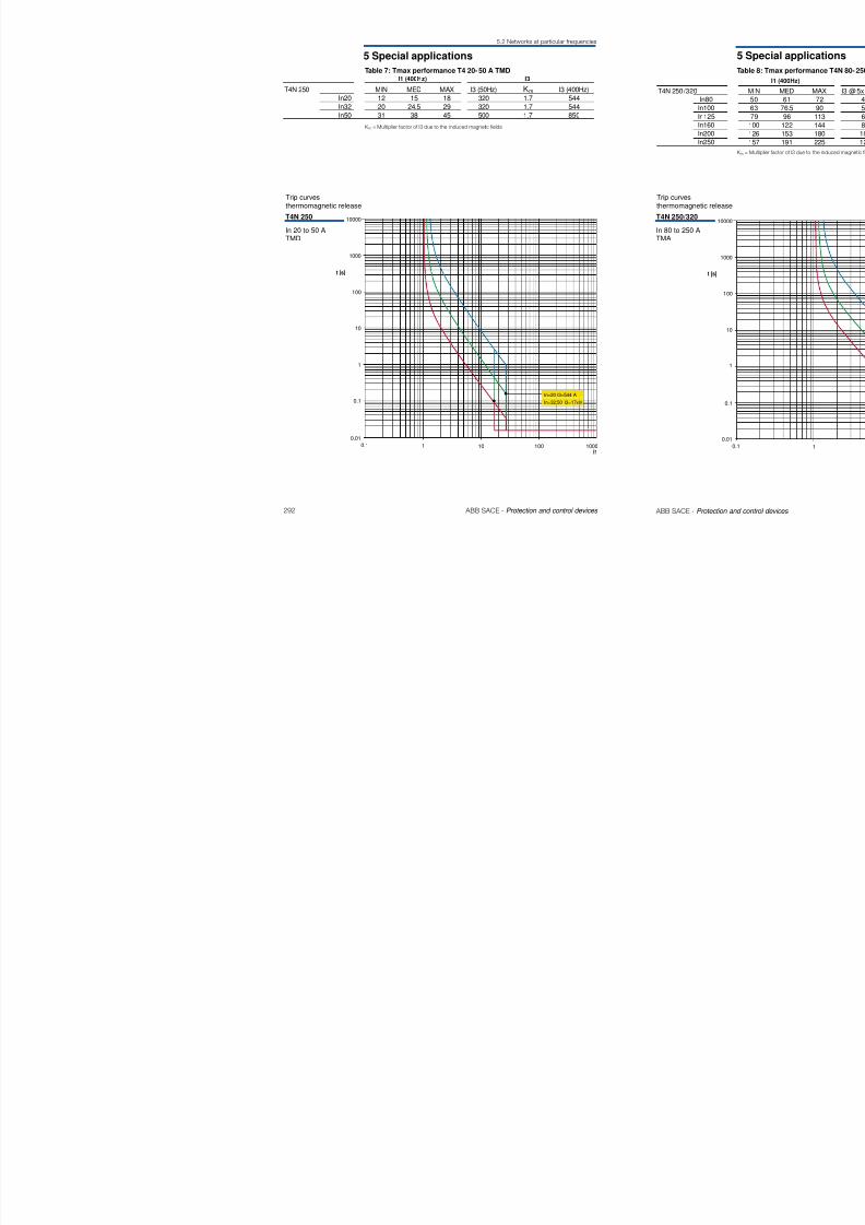
8/3/2019 ABB Electrical Install Ti On Handbook 4th Edition
http://slidepdf.com/reader/full/abb-electrical-install-ti-on-handbook-4th-edition 128/322
250 ABB SACE - Protection and control devices
4
6
8
10
13
16
20
25
32
40
50
63
80
100
125
L o a d
s .
C
T
5.5
5.5
3(1)
3(1)
T
5.5
5.5
3
T
5.5
5.5
3
3
3(1)
3(1)
T
5.5
5.5
3
3
3
T
5.5
5.5
4.5
4.5
4.5
3
3(1)
3(1)
T
10.5
10.5
7.5
7.5
5
5
5
T
5.5
T
5.5(1)
(1) Value for the supply side magnetic only T2 circuit-b reaker.(2) Value for the supply side magnetic only T2-T3 circuit-breaker.(3) Value for the supply side magnetic only T3 circuit-b reaker.(4) Value for the supply side magnetic only T4 circuit-b reaker.(5) Value for the supply side T4 In160 circuit-breaker.
-
S200L
S200L
S200L
S200L
S200L
S200L
S200L
S200L
S200L
-
-
-
-
-
S200
S200
S200
S200
S200
S200
S200
S200
S200
S200
S200
S200
-
-
-
S200M
S200M
S200M
S200M
S200M
S200M
S200M
S200M
S200M-S200P
S200M-S200P
S200M-S200P
S200M-S200P
S290
S290
S290
S200P
S200P
S200P
S200P
S200P
S200P
S200P
S200P
-
-
-
-
-
-
-
4 Protection coordination
4.2 Discrimination tables
MCCB - S2.. D @ 415V
In [A]
≤2
3
4
Icu [kA]Char. Supply s.
Version
Release
20
T
T
T
25
T
T
T
32
T
T
T
40
T
T
T
63
T
T
T
16
T
T
T
12.5
T
T
T
TM
T2 T1-T2
B, C, N, S, H, L
50
T
T
T
6
-
-
-
10
S200
S200
S200
15
S200M
S200M
S200M
25
S200P
S200P
S200P
Discrimination tables MCCB - S2..
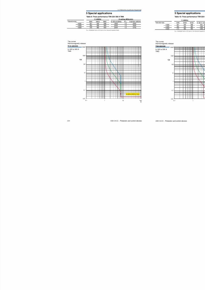
8/3/2019 ABB Electrical Install Ti On Handbook 4th Edition
http://slidepdf.com/reader/full/abb-electrical-install-ti-on-handbook-4th-edition 129/322
252 ABB SACE - Protection and control devices
4
6
8
10
13
1620
25
32
40
50
63
80
100
125
L
o a d
s .
D
T
5.5
5.5
3 (1)
T
5.5
5.5
3
T
5.5
5.5
3
2(1)
2(1)
2(1)
T
5.5
5.5
3
2
2
T
10.5
10.5
5
3
33
2.5
T
5.5
T
5.5 (1)
(1) Value for the supply side magnetic only T2 circuit-breaker.(2) Value for the supply side magnetic only T2-T3 circuit-breaker.(3) Value for the supply side magnetic only T3 circuit-breaker.(4) Value for the supply side magnetic only T4 circuit-breaker.(5) Value for the supply side T4 In160 circuit-breaker.
T
5.5
5.5
3
2
22
2(1)
-
-
-
-
--
-
-
-
-
-
-
-
-
S200
S200
S200
S200
S200
S200S200
S200
S200
S200
S200
S200
-
-
-
S200M
S200M
S200M
S200M
-
S200MS200M
S200M
S200M-S200P
S200M-S200P
S200M-S200P
S200M-S200P
S290
S290
-
S200P
S200P
S200P
S200P
S200P
S200PS200P
S200P
-
-
-
-
-
-
-
4 Protection coordination
4.2 Discrimination tables
MCCB - S2.. K @ 415V
In [A]
≤2
3
4
Icu [kA]Char. Supply s.
Version
Release
20
T
T
T
25
T
T
T
32
T
T
T
40
T
T
T
63
T
T
T
16
T
T
T
12.5
T
T
T
TM
T2 T1-T2
B, C, N, S, H, L
50
T
T
T
6
-
-
10
S200
S200
S200
15
S200M
S200M
S200M
25
S200P
S200P
S200P
Discrimination tables MCCB - S2..
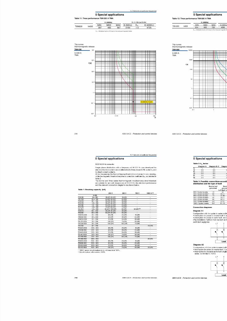
8/3/2019 ABB Electrical Install Ti On Handbook 4th Edition
http://slidepdf.com/reader/full/abb-electrical-install-ti-on-handbook-4th-edition 130/322
254 ABB SACE - Protection and control devices
4
6
8
10
13
16
20
25
32
40
50
63
80
100
125
L o a d
s .
K
T
5.5
5.5
3(1)
T
5.5
5.5
3
T
5.5
5.5
3
2(1)
2(1)
2(1)
T
5.5
5.5
3
3
3
T
10.5
10.5
6
5
4.5
3.5
3.5
T
5.5
T
5.5(1)
(1) Value for the supply side magnetic only T2 circuit-b reaker.(2) Value for the supply side magnetic only T2-T3 circuit-breaker.(3) Value for the supply side magnetic only T3 circuit-b reaker.(4) Value for the supply side magnetic only T4 circuit-b reaker.(5) Value for the supply side T4 In160 circuit-breaker.
T
5.5
5.5
3
3
3
3
2(1)
-
-
-
-
-
-
-
-
-
-
-
-
-
-
-
S200
S200
S200
S200
-
S200
S200
S200
S200
S200
S200
S200
-
-
-
S200M
S200M
S200M
S200M
-
S200M
S200M
S200M
S200M-S200P
S200M-S200P
S200M-S200P
S200M-S200P
S290
S290
-
S200P
S200P
S200P
S200P
S200P
S200P
S200P
S200P
-
-
-
-
-
-
-
4 Protection coordination
4.2 Discrimination tables
MCCB - S2.. Z @ 400V
In [A]
≤2
3
4
Icu [kA]Char. Supply s.
Version
Release
20
T
T
T
25
T
T
T
32
T
T
T
40
T
T
T
63
T
T
T
16
T
T
T
12.5
T
T
T
TM
T2 T1-T2
B, C, N, S, H, L
50
T
T
T
6
-
-
-
10
S200
S200
S200
15
-
-
-
25
S200P
S200P
S200P
Discrimination tables MCCB - S2..
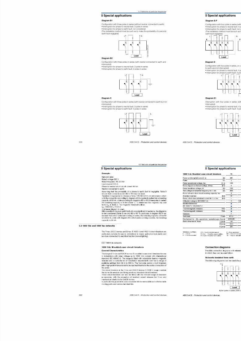
8/3/2019 ABB Electrical Install Ti On Handbook 4th Edition
http://slidepdf.com/reader/full/abb-electrical-install-ti-on-handbook-4th-edition 131/322
256 ABB SACE - Protection and control devices
6
8
10
13
1620
25
32
40
50
63
80
100
125
L o
a d
s .
Z
5.5
5.5
3(1)
3(1)
5.5
5.5
3
5.5
5.5
3
3
3
(1)
3(1)
5.5
5.5
3
3
3
10.5
10.5
8
7.5
55
5
5.55.5 (1)
(1) Value for the supply side magnetic only T2 circuit-b reaker.(2) Value for the supply side magnetic only T2-T3 circuit-breaker.(3) Value for the supply side magnetic only T3 circuit-b reaker.(4) Value for the supply side magnetic only T4 circuit-b reaker.
5.5
5.5
4.5
4.5
4.53
3(1)
3(1)
-
-
-
-
--
-
-
-
-
-
-
-
-
S200
S200
S200
-
S200S200
S200
S200
S200
S200
S200
-
-
-
-
-
-
-
--
-
S200P
S200P
S200P
S200P
-
-
-
S200P
S200P
S200P
S200P
S200PS200P
S200P
-
-
-
-
-
-
-
4 Protection coordination
4.2 Discrimination tables
MCCB - T1 @ 415V
T1 T2 T3 T4
N,S,H,L N,S N,S,H,L,V
TM TM,M EL TM,M TM,M
Iu
[A] 160 160 250 250
n[A] 160 160 25 63 100 160 160 200 250 20 25 32 50 80 100 125 160 200 250
16 3 3 3 3 3 3 4 5 10* 10 10 10 10 10 10
20 3 3 3 3 3 3 4 5 10* 10 10 10 10 10 10
25 3 3 3 3 3 3 4 5 10* 10 10 10 10 10 10
Supply s.
Version
Release
ILoad s.
B,C,
N
160
Discrimination tables MCCB - MCCB
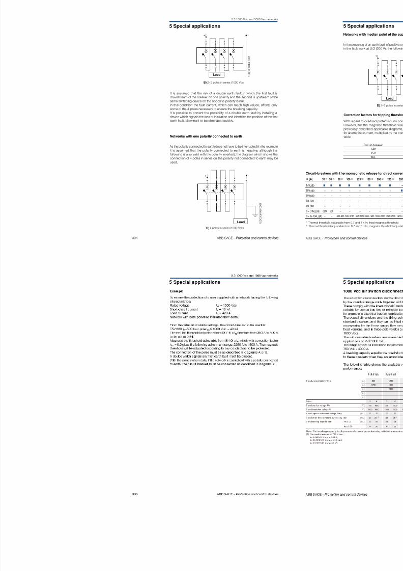
8/3/2019 ABB Electrical Install Ti On Handbook 4th Edition
http://slidepdf.com/reader/full/abb-electrical-install-ti-on-handbook-4th-edition 132/322
258ABB SACE -
Protection and control devices
* Value for the supply side magnetic only circuit -breaker.**Values valid only with PR232/P, PR331/P and PR332/P electronic releases***Available only with Iu ≤ 1250A
25 3 3 3 3 3 3 4 5 10 10 10 10 10 10 10
32 3 3 3 3 3 4 5 10* 10 10 10 10 10
40 3 3 3 3 3 4 5 10* 10 10 10 10 10
B 50 3 3 3 3 3 4 5 10* 10 10 10 10
63 3 3 3 3 4 5 10* 10 10 10
80 3 4 5 10 10 10
100 5 10* 10 10
125 10* 10
160
T1 TM 160
B
C
N
4 Protection coordination
4.2 Discrimination tables
MCCB T2 @ 415V
Monte T1 T2 T3 T4
Versione B,
C, N,S,H,L N,S N,S,H,L,V
N
Relè TM TM,M EL TM,M TM,M
Iu
[A] 160 160 250 250
Valle In
[A] 160 160 25 63 100 160 160 200 250 20 25 32 50 80 100 125 160 200 250
1.6-2.5 T T T T T T T T T T T* T T T T T T T T
3.2 T T T T T T T T T T T* T T T T T T T T
4-5 T T T T T T T T T T T* T T T T T T T T
6 3 10 10 10 10 10 10 10 15 40 T T* T T T T T T T T
Supply s.
Version
Release
Load s.
160
Discrimination tables MCCB - MCCB
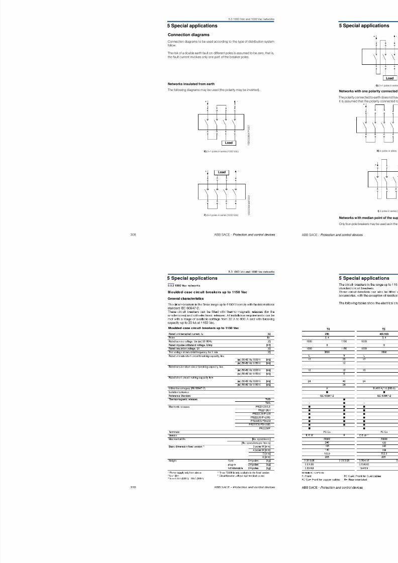
8/3/2019 ABB Electrical Install Ti On Handbook 4th Edition
http://slidepdf.com/reader/full/abb-electrical-install-ti-on-handbook-4th-edition 133/322
260 ABB SACE - Protection and control devices
6.3 10 10 10 10 10 10 10 15 40 T T T T T T T T T T
8 10 10 10 10 10 10 10 15 40 T* T T T T T T T T
10 10 10 10 10 10 10 10 15 40 T* T T T T T T T T
12.5 3 3 3 3 3 3 4 5 T T T T T T T T
16 3 3 3 3 3 3 4 5 70 70 70 70 70 70
TM 160 20 3 3 3 3 3 3 4 5 55* 55 55 55 55 5525 3 3 3 3 3 3 4 5 40* 40 40 40 40 40
32 3 3 3 3 3 4 5 40* 40 40 40 40 40
40 3 3 3 3 3 4 5 30* 30* 30 30 30 30
50 3 3 3 3 3 4 5 30* 30* 30 30 30 30
63 3 3 3 3 4 5 30* 30* 30* 30 30 30
80 3 3* 4 5 25* 25* 25* 25 25
100 4 5 25* 25* 25* 25
125 25* 25*
160 25*
10 3 4 25 25 25 25 25 25 25
25 3 4 25 25 25 25 25 25
EL 160 63 3 4 25 25 25
100 3 4 25
160 3 4
N
S
H
L
T2
* Value for the supply side magnetic only circuit-breaker.**Values valid only with PR232/P, PR331/P and PR332/P electronic releases***Available only with Iu ≤ 1250A
4 Protection coordination
4.2 Discrimination tables
Discrimination tables MCCB - MCCB
MCCB - T3 @ 415V
T1 T2 T3 T4
B,
NTM TM, M EL TM.M TM.M
Iu
[A] 160 160 250 250
In
[A] 160 160 25 63 100 160 160 200 250 20 25 32 50 80 100 125 160 200 250
63 3 4 5 7* 7 7 7
80 3* 4 5 7* 7 7
100 4* 5 7* 7* 7N
Supply s.
Version
Release
Load s.
C, N,S,H,L N,S N,S,H,L,V
160
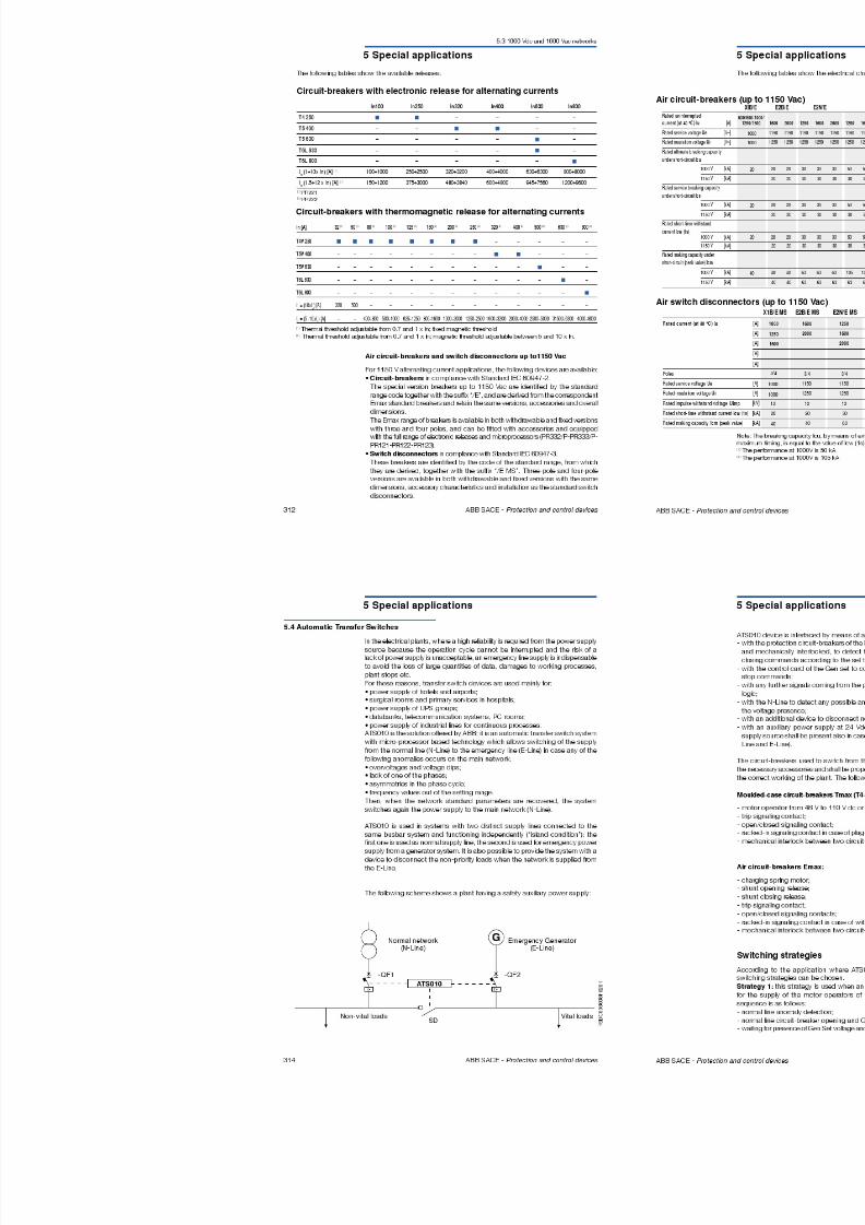
8/3/2019 ABB Electrical Install Ti On Handbook 4th Edition
http://slidepdf.com/reader/full/abb-electrical-install-ti-on-handbook-4th-edition 134/322
262 ABB SACE - Protection and control devices
MCCB - T4 @ 415V
125 7*
160
200
T3 TM 160
250
N
S
Relè TM
Iu
Valle In [A] 320 400 50020 T T T
25 T T T
32 T T T
50 T T T
250
80 T T T
N. TM 100 50 50
S. 125 50
T4 H. 160
L. 200
V 250
100 50 50 50
EL250 160 50 50 50
250 50
320 320
Supply s.
Version
Release
Load s.
EL
400 630
320 400 630T T T
T T T
T T T
T T T
T T T
50 50 50
50 50 50
50 50 50
50 50 50
50 50
50 50 50
50 50 50
50 50
50
N,S,H,L,V
[A] 400 630
T5 T6
N,S,H,L
TM,M EL
630 800 630 800 1000
630 800 630 800 1000T T T T T
T T T T T
T T T T T
T T T T T
T T T T T
T T T T T
T T T T T
T T T T T
T T T T T
T T T T T
T T T T T
T T T T T
T T T T T
T T T T T
T7 S7
S,H,LS,H,L,V*
ELEL
1250 1600
1250 16001000**
800
800**
1000 1250 1600
160012501000T
T
T
T
T
T
T
T
T
T
T
T
T
T
T
T
T
T
T
T
T
T
T
T
T
T
T
T
T
T
T
T
T
T
T
T
T
T
T
T
T
T
T
T
T
T
T
T
T
T
T
T
T
T
T
T
T
T
T
T
T
T
T
T
T
T
T
T
T
T
T
T
T
T
T
T
T
T
T
T
T
T
T
T
T
T
T
T
T
T
T
T
T
T
T
T
T
T
* Value for the supply side magnetic only c ircuit-breaker.**Values valid only with PR232/P, PR331/P and PR332/P electronic releases***Available only with Iu ≤ 1250A
*Available only with Iu ≤ 1250A**Values valid only with PR232/P, PR331/P and PR332/P electronic releases
4 Protection coordination
4.2 Discrimination tables
MCCB - T5 @ 415V
Iu
[A]
In
[A]
400320
N,TM
400S, 630 500T5H,
Supply s.
Version
Release
Load s.
N,S,H,L
T6
630 800 630 800 1000
630 800 630 800 1000
TM,M EL
30 30 30 3 0 30
30 30 30
30 30
T7 S7
S,H,LS,H,L,V*
ELEL
1250 1600
1250 16001000**
800
800**
1000 1250 1600
160012501000
T
T
T
T
T
T
T
T
T
T
T
T
T
T
T
T
T
T
T
T
T
Discrimination tables MCCB - MCCB
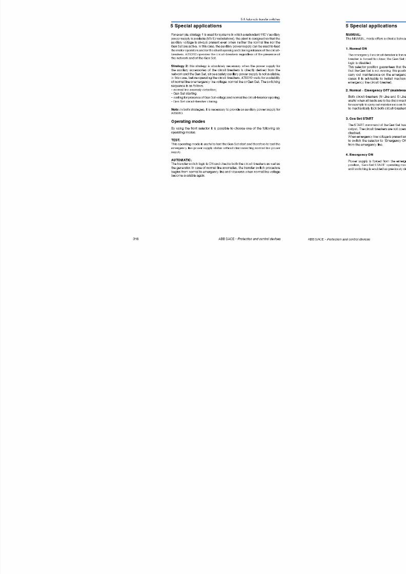
8/3/2019 ABB Electrical Install Ti On Handbook 4th Edition
http://slidepdf.com/reader/full/abb-electrical-install-ti-on-handbook-4th-edition 135/322
264 ABB SACE - Protection and control devices
H,L,
400320
V EL 400
630 630
30 30 30 3 0 30
30 30 30 3 0 30
30
T
T
T
T
T
T
T
T
T
T
T
T
T
T
T
T
T
T
T
T
T
MCCB - T6 @ 415V
Supply s.
Version
Release
Load s.[A]Iu
T6
[A]In
630
800TM
EL
630
800
1000
630
800
630
800
1000
N,S,H,L, V
T7 S7
S,H,LS,H,L,V*
ELEL
1250 16001250 16001000**
800800**
1000 1250 1600160012501000
40
40
40
40
40
40
40
40
40
40
40
40
40
40
40
40
40
40
40
40
40
40
40
40
40
40
*Available only with Iu ≤ 1250A
**Values valid only with PR232/P, PR331/P and PR332/P electronic releases
*Available only with Iu ≤ 1250A, maximum selectivity values is 15kA**Values valid only with PR232/P, PR331/P and PR332/P electronic releases
4 Protection coordination
The tables shown give the short-circuit current value (in kA) for which the back-up protection is verified for the chosen circuit-breaker combination, at voltagesfrom 380 up to 415 V. These tables cover all the possible combinations betweenABB SACE moulded-case circuit-breakers Isomax and Tmax and those between
the above mentioned circuit-breakers and ABB MCBs.
Notes for a correct interpretation of the coordinationtables:
4.3 Back-up tables
Isomax @ 415V ac
Version Icu [kA]
Tmax @ 415V ac
Version Icu [kA]
Emax @ 415V ac
Version Icu [kA]
B 42
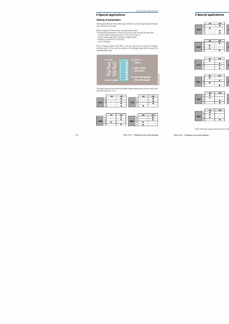
8/3/2019 ABB Electrical Install Ti On Handbook 4th Edition
http://slidepdf.com/reader/full/abb-electrical-install-ti-on-handbook-4th-edition 136/322
266 ABB SACE - Protection and control devices
S 50
H 65
L 100
B 16
C 25
N 36
S 50
H 70L (for T2) 85
L (for T4-T5) 120
L (for T6) 100
V (for T7) 150
V 200
For MCCB (Moulded-case circuit-breaker)ACB (Air circuit-breaker)TM = thermomagnetic release
– TMD (Tmax)
– TMA (Tmax) – T adjustable M adjustable (Isomax)
M = magnetic only release
– MF (Tmax) – MA (Tmax)
EL = elettronic release
For MCB (Miniature circuit-breaker):B = charateristic trip (I3=3...5In)C = charateristic trip (I3=5...10In)
D = charateristic trip (I3=10...20In)
K = charateristic trip (I3=8...14In)Z = charateristic trip (I3=2...3In)
Keys
B 42
N 65*
S 75**
H 100
L 130***
V 150****
* For Emax E1 version N Icu=50kA** For Emax E2 version S Icu=85kA*** For Emax X1 version L Icu=150kA**** For Emax E3 version V Icu=130kA
4 Protection coordination
MCB - MCB @ 415V
S200L
S200
S200M
S200P
S280
Supply s.
Icu [kA]
Char.
Load s.
C
B,C,K,Z
B,C,D
B, C,
D, K, Z
B C
6
10
15
25
15
6
In [A]
6..40
0.5..63
0.5..63
0.5..25
32..63
80 100
S200L S200 S200M S200P S280 S290 S500
C
6
6..40
B-C
10
0.5..63
10
B-C
15
0.5..63
15
15
B-C
25
0.5..25
25
25
25
B-C
15
32..63
15
15
B-C
6
80, 100
C
15
80..125
15
15
B-C
50
6..63
50
50
50
50
4.3 Back-up tables
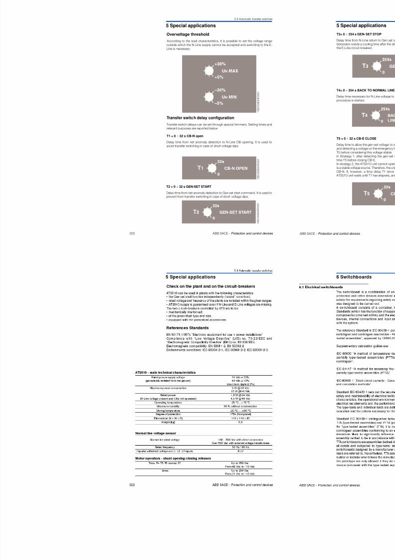
8/3/2019 ABB Electrical Install Ti On Handbook 4th Edition
http://slidepdf.com/reader/full/abb-electrical-install-ti-on-handbook-4th-edition 137/322
268 ABB SACE - Protection and control devices
MCCB - MCB @ 415V
S280
S290
S500
B,C
C,D
B,C,D
6
15
50
80, 100
80..125
6..63
Load s. Char. In [A] Icu [kA]
Version
Supply s.
S200L
S200
S200M
S200P
S280
S290
S500
C
B, C, K, Z
B, C, D
B, C, D,
K, Z
B, C
C, D
B, C, D
6..10
13..40
0.5..10
13..63
0.5..10
13..63
0.5..10
13..25
32..63
80, 100
80,125
6..63
6
10
15
25
15
6
15
50
T1 T1 T1 T2 T3 T4 T2 T3 T4 T2 T4 T2 T4 T4
L L VHSNCB
85 120 2007050362516
16
16
16
25
25
25
30
30
30
36
36
36
36
36
36
35
35
50
36
16
36
16
36
25
36
30
25
16
30
16
16
16
25
16
25
30
30
30
16
30
36
36
36
36
36
36
36
36
30
30
50
50
50
36
50
40
16
40
16
40
25
40
30
25
16
30
40
40
40
40
40
40
30
30
40
40
70
60
70
60
60
36
70
70
40
40
40
40
40
40
30
30
70
40
40
85
60
85
60
60
36
85
85
40
40
40
40
40
40
40
40
40
30
30
120
40
40
40
30
30
200 1 S D C 0 0 8 0 3 5 F 0 2 0 1
4 Protection coordination
4.4 Coordination tables between circuit-
breakers and switch disconnectors
The tables shown give the values of the short-circuit current (in kA) for whichback-up protect ion is verified by the pre-selected combination of circuit-breakerand switch disconnector, for voltages between 380 and 415 V. The tables cover
the possible combinations of moulded-case circuit-breakers in the ABB SACEIsomax and Tmax series, with the switch disconnectors detailed above.
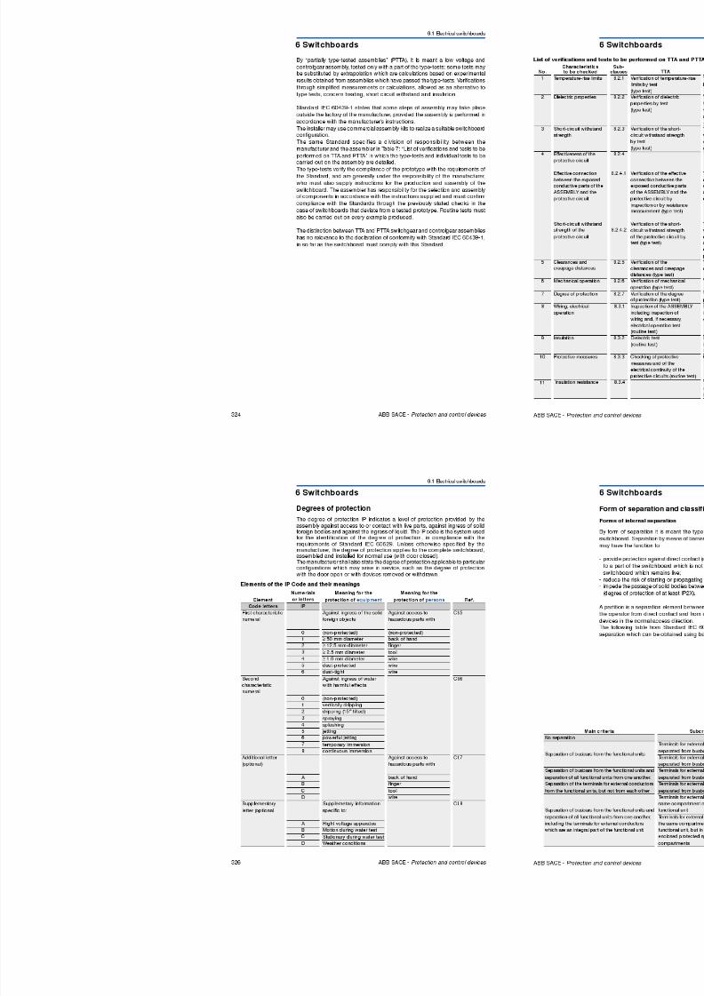
8/3/2019 ABB Electrical Install Ti On Handbook 4th Edition
http://slidepdf.com/reader/full/abb-electrical-install-ti-on-handbook-4th-edition 138/322
270 ABB SACE - Protection and control devices
T1D 160 T3D 250 T4D 320 T5D 400
T1B
T1C
T1N
T2N
T2S
T2H
T2L
T3N
T3ST4N
T4S
T4H
T4L
T4V
T5N
T5S
T5H
T5L
T5V
T6N
T6S
T6H
T6L
T7S
T7H
T7L
T7V
S7S
S7H
S7L
T5D 630 T6D415 V
36*
50*
70*
120*
200*
* for T4 250 or T4 320 only with I1 setting at 250 A.
4 Protection coordination
4.4 Coordination tables between circuit-breakers and switch disconnectors
U Ur = 400V
Example:From the coordination table on page 270-271 it can be seen that circuit-breakerT2S160 is able to protect the switch disconnector T1D160 up to a short-circuitcurrent of 50 kA (higher than the short-circuit current at the installation point).Overload protection is also verified, as the rated current of the breaker is nothigher than the size of the disconnector.
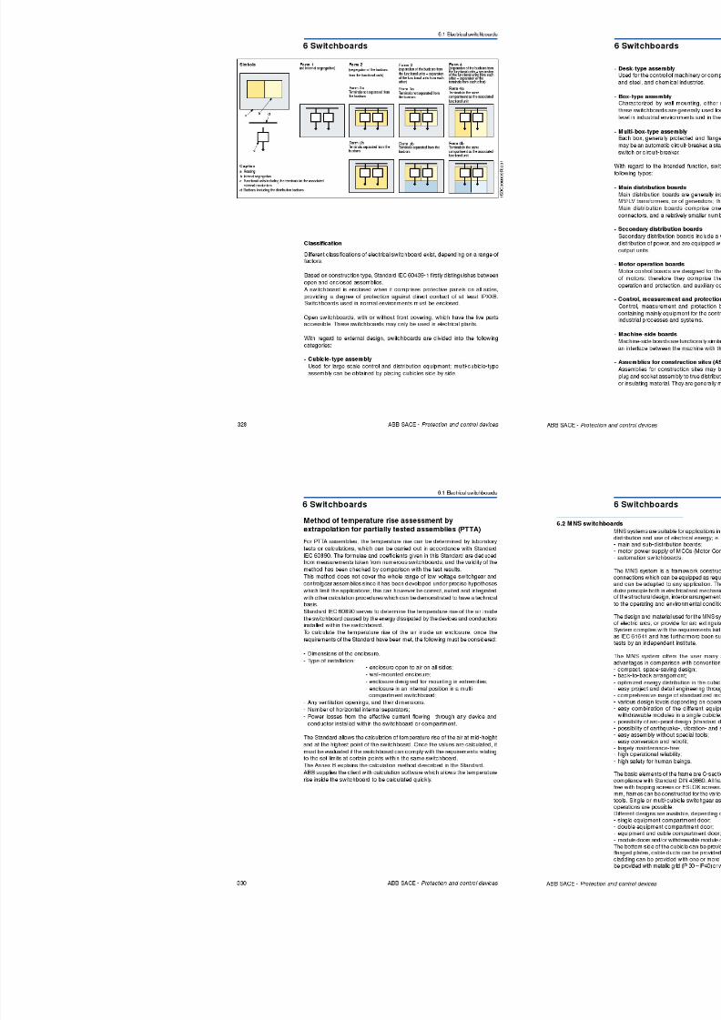
8/3/2019 ABB Electrical Install Ti On Handbook 4th Edition
http://slidepdf.com/reader/full/abb-electrical-install-ti-on-handbook-4th-edition 139/322
272 ABB SACE - Protection and control devices
1 S D C
0 0 8 0 1 8 F 0 0 0 1
U Ur 400V
T2S160
T1D 160
I = 40kAk
Cable
8/3/2019 ABB Electrical Install Ti On Handbook 4th Edition
http://slidepdf.com/reader/full/abb-electrical-install-ti-on-handbook-4th-edition 140/322
5 Special applications
5.1 Direct current networks
U
a b
c
R
1 S D C 0 0 8 0 2 0 F 0 0 0 1
Network with both polarities insulated from earth
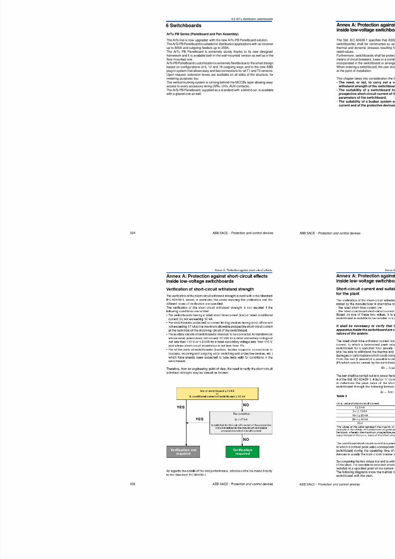
8/3/2019 ABB Electrical Install Ti On Handbook 4th Edition
http://slidepdf.com/reader/full/abb-electrical-install-ti-on-handbook-4th-edition 141/322
276 ABB SACE - Protection and control devices
+ -
1 S D C 0 0 8 0 2 1 F 0 0 0 1
Load
• Fault a: the fault, without negligible impedance, between the two polarities
sets up a short-circuit current to which both polarities contribute to the full
voltage, according to which the breaking capacity of the breaker must beselected.
• Fault b: the fault between the polarity and earth has no consequences from
the point of view of the function of the installation.• Fault c: again, this fault between the polarity and earth has no consequences
from the point of view of the function of the installation.
In insulated networks it is necessary to install a device capable of signalling the
presence of the first earth fault in order to eliminate it. In the worst conditions,
when a second earth fault is verified, the breaker may have to interrupt the
short-circuit current with the full voltage applied to a single polarity and therefore
with a breaking capacity which may not be sufficient.
In networks with both polarities insulated from earth it is appropriate to dividethe number of poles of the breaker necessary for interruption on each polarity
(positive and negative) in such a way as to obtain separation of the circuit.
The diagrams to be used are as follows:
Diagram A
Three-pole breaker with one pole per polarity
5 Special applications
5.1 Direct current networks
1 S D C 0 0 8 0 2 5 F 0 0 0 1
+ -
Load
Diagram F
Four-pole breaker with two poles in series per polarity
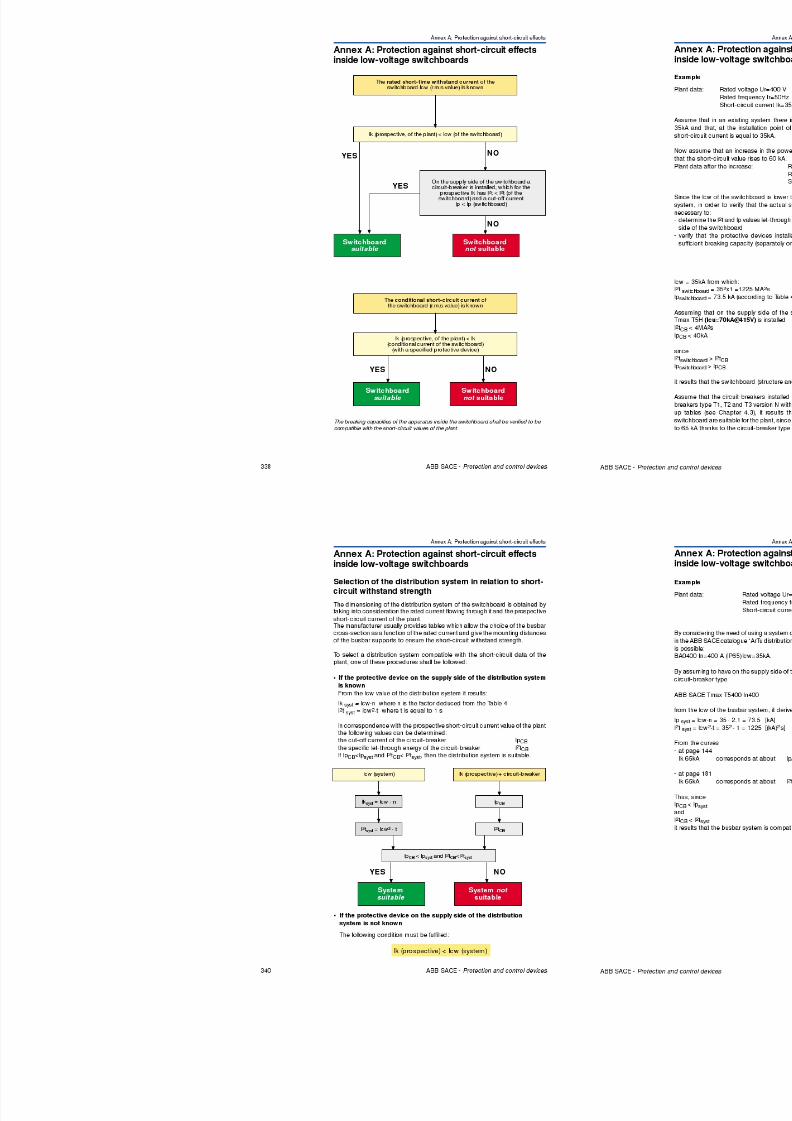
8/3/2019 ABB Electrical Install Ti On Handbook 4th Edition
http://slidepdf.com/reader/full/abb-electrical-install-ti-on-handbook-4th-edition 142/322
278 ABB SACE - Protection and control devices
U
a b
c
R
1 S D C 0 0 8 0 2 6 F 0 0 0 1
Network with one polarity connected to earth
• Fault a: the fault between the two polarities sets up a short-circuit current to
which both polarities contribute to the full voltage U, according to which the
breaking capacity of the breaker is selected.• Fault b: the fault on the polarity not connected to earth sets up a current
which involves the over-current protection according to the resistance of theground.
• Fault c: the fault between the polarity connected to earth and earth has no
consequences from the point of view of the function of the installation.
In a network with one polarity connected to earth, all the poles of the breaker
necessary for protection must be connected in series on the non-earthed
polarity. If isolation is required, it is necessary to provide another breaker pole
on the earthed polarity.
5 Special applications
5.1 Direct current networks
S D C 0 0 8 0 3 0 F 0 0 0 1
+ -
Load
Diagram E
Four-pole breaker with three poles in series on the polarity not connected to
earth, and one pole on the remaining polarity
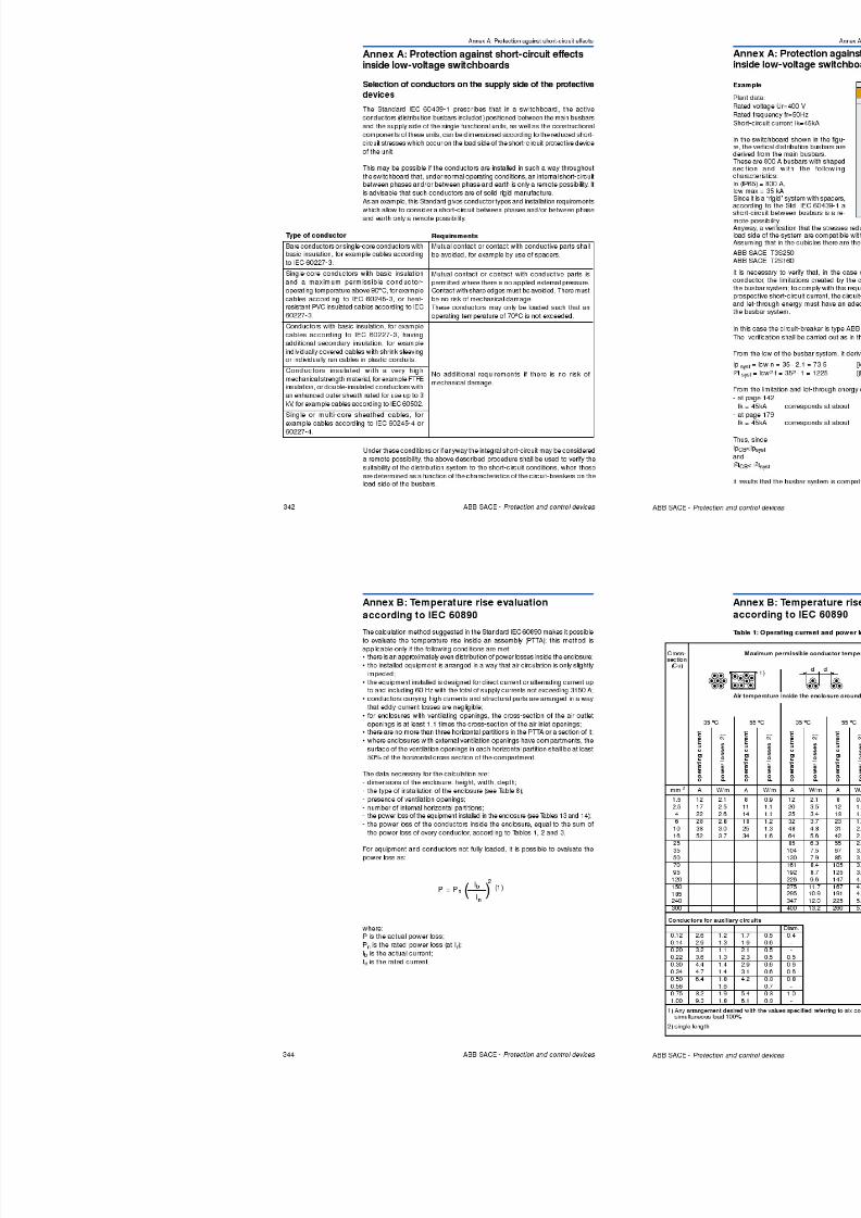
8/3/2019 ABB Electrical Install Ti On Handbook 4th Edition
http://slidepdf.com/reader/full/abb-electrical-install-ti-on-handbook-4th-edition 143/322
280 ABB SACE - Protection and control devices
1 S
1 S D C 0 0 8 0 3 1 F 0 0 0 1
+ -
1 S D C 0 0 8 0 3 2 F 0 0 0 1
+ -
Load
Load
Load
Diagrams to be used without circuit isolation are as follows:
Diagram C
Three-pole breaker with three poles in series
Diagram H
Four-pole breaker with series of two poles in parallel
5 Special applications
5.1 Direct current networks
1 S D C 0 0 8 0 3 6 F 0 0 0 1
+ -
Load
Diagram G
Four-pole breaker with two poles in parallel per polarity
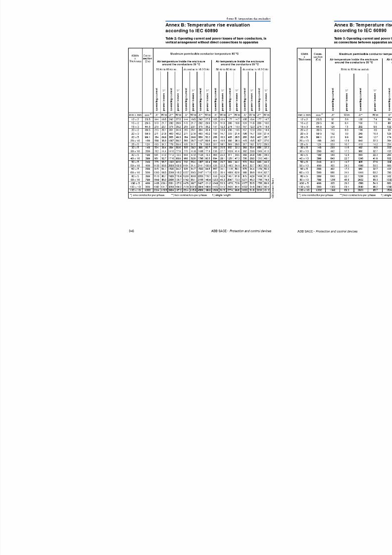
8/3/2019 ABB Electrical Install Ti On Handbook 4th Edition
http://slidepdf.com/reader/full/abb-electrical-install-ti-on-handbook-4th-edition 144/322
282 ABB SACE - Protection and control devices
1 S D C
0 0 8 0 3 7 F 0 0 0 1
+ -
Load
Diagram F
Four-pole breaker with two poles in series per polarity
Use of switching devices in direct current
Parallel connection of breaker poles
According to the number of poles connected in parallel, the coefficients detailed
in the following table must be applied:
Table 1: Correction factor for poles connected in parallelnumber of poles in parallel 2 3 4 (neutral 100%)
reduction factor of dc carrying capacity 0.9 0.8 0.7
breaker current carrying capacity 1.8xIn 2.4xIn 2.8xIn
The connections which are external from the breaker terminals must be carried
out by the user in such a way as to ensure that the connection is perfectly
balanced.
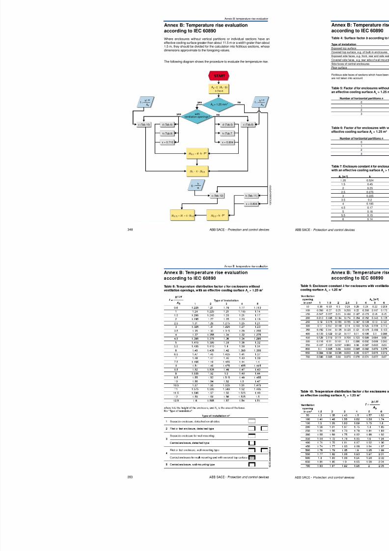
8/3/2019 ABB Electrical Install Ti On Handbook 4th Edition
http://slidepdf.com/reader/full/abb-electrical-install-ti-on-handbook-4th-edition 145/322
5 Special applications
5.2 Networks at particular frequencies
Table 1: Tmax performance T1 16-63 A TMD
I1 (400Hz) I3
T1B 160T1C 160T1N 160
MIN MED MAX I3 (50Hz) Km I3 (400Hz)In16 10 12 14 500 2 1000In20 12 15 18 500 2 1000In25 16 19 22 500 2 1000
In32 20 24.5 29 500 2 1000In40 25 30.5 36 500 2 1000In50 31 38 45 500 2 1000In63 39 48 57 630 2 1260
Km = Multiplier factor of I3 due to the induced magnetic fields
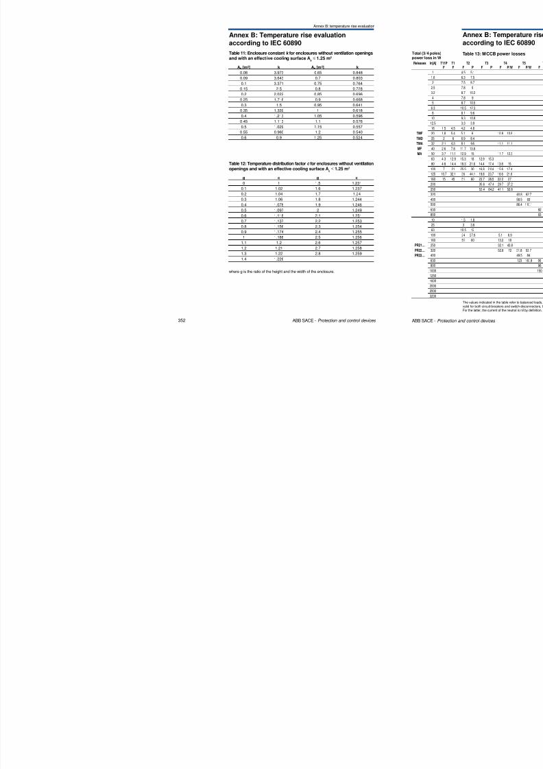
8/3/2019 ABB Electrical Install Ti On Handbook 4th Edition
http://slidepdf.com/reader/full/abb-electrical-install-ti-on-handbook-4th-edition 146/322
286 ABB SACE - Protection and control devices
Trip curvesthermomagnetic release
T1 B/C/N 160
In 16 to 63 A
TMD
I1
t [s]
1
0.01
1000
0.1
0.1 100
1
10
100
1000
10
In=16 I3=1000 A
In=20 I3=1000 AIn=25 I3=1000 A
In=32 I3=1000 A
In=40 I3=1000 A
In=50-63 I3=1000 A
5 Special applications
5.2 Networks at particular frequencies
Table 3: Tmax performance T2 1.6-80 A TMD
I1 (400Hz) I3
T2N 160 MIN MED MAX I3 (50Hz) I3 (400Hz)
In1.6 1 1.2 1.4 16 1.7 27.2
In2 1.2 1.5 1.8 20 1.7 34
In2.5 1.5 1.9 2.2 25 1.7 42.5
In3.2 2 2.5 2.9 32 1.7 54.4
In4 2.5 3 3.6 40 1.7 68In5 3 3.8 4.5 50 1.7 85In6.3 4 4.8 5.7 63 1.7 107.1In8 5 6.1 7.2 80 1.7 136
In10 6.3 7.6 9 100 1.7 170In12.5 7.8 9.5 11.2 125 1.7 212.5In16 10 12 14 500 1.7 850
In20 12 15 18 500 1.7 850In25 16 19 22 500 1.7 850
In32 20 24 5 29 500 1 7 850
Km
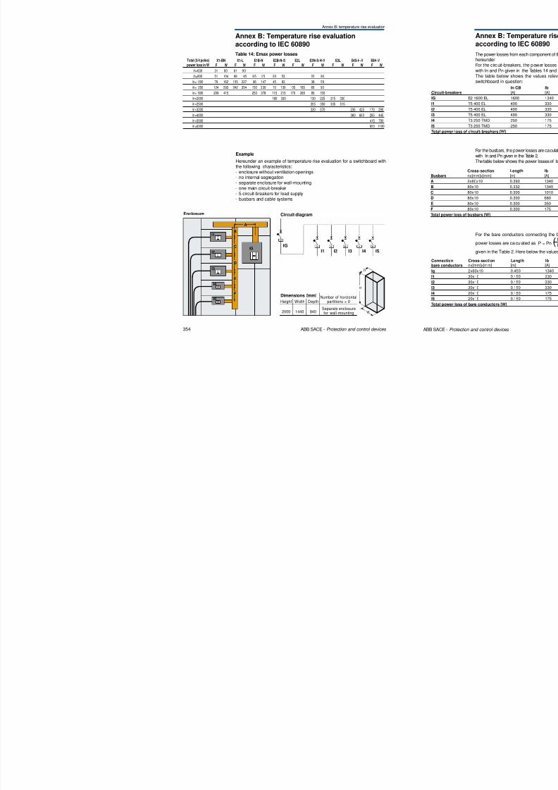
8/3/2019 ABB Electrical Install Ti On Handbook 4th Edition
http://slidepdf.com/reader/full/abb-electrical-install-ti-on-handbook-4th-edition 147/322
288 ABB SACE - Protection and control devices
I1
t [s]
1
0.01
1000
0.1
0.1 100
1
10
100
1000
10
In=16 I3=850 A
In=20 I3=850 A
In=25 I3=850 A
In=32 I3=850 A
In=40 I3=850 A
In=1.6 to 12.5 I3=17xIn
In=50 to 80 I3=17xIn
Trip curvesthermomagnetic release
T2N 160
In 1.6 to 80 ATMD
Km = Multiplier factor of I3 due to the induced magnetic fields
In32 20 24.5 29 500 1.7 850
In40 25 30.5 36 500 1.7 850
In50 31 38 45 500 1.7 850
In63 39 48 57 630 1.7 1071In80 50 61 72 800 1.7 1360
5 Special applications
5.2 Networks at particular frequencies
Trip curves
th ti l
Table 5: Tmax performance T3 63-250 A TMG
Km = Multiplier factor of I3 due to the induced magnetic fields
I1 (400Hz) I3 (Low magnetic setting)
T3N 250 MIN MED MAX I3 (50Hz) I3 (400Hz)In63 39 48 57 400 1.7 680In80 50 61 72 400 1.7 680In100 63 76.5 90 400 1.7 680In125 79 96 113 400 1.7 680
In160 100 122 144 480 1.7 816In200 126 153 180 600 1.7 1020In250 157 191 225 750 1.7 1275
Km

8/3/2019 ABB Electrical Install Ti On Handbook 4th Edition
http://slidepdf.com/reader/full/abb-electrical-install-ti-on-handbook-4th-edition 148/322
290 ABB SACE - Protection and control devices
I1
t [s]
1
0.01
1000
0.1
0.1 100
1
10
100
1000
10
In=100 I3=680 A
In=125 I3=680 A
In=160,200,250 I3=5.1xIn
In=80 I3=680 A
In=63 I3=680 A
thermomagnetic release
T3N 250
In 63 to 250 ATMG
5 Special applications
5.2 Networks at particular frequencies
Trip curvesthermomagnetic release
Table 7: Tmax performance T4 20-50 A TMD
Km = Multiplier factor of I3 due to the induced magnetic fields
I1 (400Hz) I3
T4N 250 MIN MED MAX I3 (50Hz) I3 (400Hz)
In20 12 15 18 320 1.7 544
In32 20 24.5 29 320 1.7 544
In50 31 38 45 500 1.7 850
Km
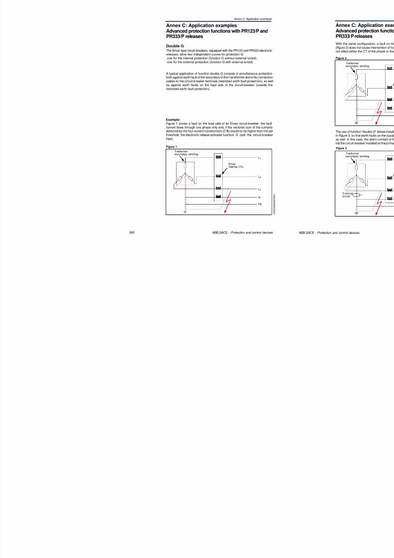
8/3/2019 ABB Electrical Install Ti On Handbook 4th Edition
http://slidepdf.com/reader/full/abb-electrical-install-ti-on-handbook-4th-edition 149/322
292 ABB SACE - Protection and control devices
thermomagnetic release
T4N 250
In 20 to 50 ATMD
I1
t [s]
1
0.01
1000
0.1
0.1 100
1
10
100
1000
10
10000
In=20 I3=544 A
In=32;50 I3=17xIn
5 Special applications
5.2 Networks at particular frequencies
Trip curvesthermomagnetic release
T5 N 400/630
I 320 t 500 A
Table 9: Tmax performance T5N 320-500 A TMA
Km = Multiplier factor of I3 due to the induced magnetic fields
I1 (400Hz) I3 setting (MIN=5xIn)
T5N400/630 MAX I3 @5xIn(50Hz) I3@ 5xIn (400 Hz)
In320 201 244 288 1.5
In400 252 306 360 1.5
In500 315 382 450 1.5
Km
1600
2000
2500
2400
3000
3750
MEDMIN
10000
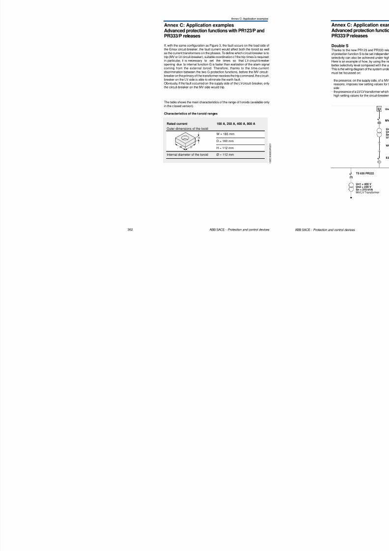
8/3/2019 ABB Electrical Install Ti On Handbook 4th Edition
http://slidepdf.com/reader/full/abb-electrical-install-ti-on-handbook-4th-edition 150/322
294 ABB SACE - Protection and control devices
In 320 to 500 ATMA
I1
t [s]
1
0.01
100
0.1
0.1 10
1
10
100
1000
In=320 to In500 I3=7.5xIn
5 Special applications
5.2 Networks at particular frequencies
Trip curvesthermomagnetic release
T6N 630
In 630 A
I1 (400Hz) I3 = 5÷10In (set I3=5In)
T6N630MIN MED MAX I3 (50Hz) I3 (400Hz)
397 482 567 3150 1.5 4725In630
Km
Table 11: Tmax performance T6N 630 A TMA
Km = Multiplier factor of I3 due to the induced magnetic fields
104
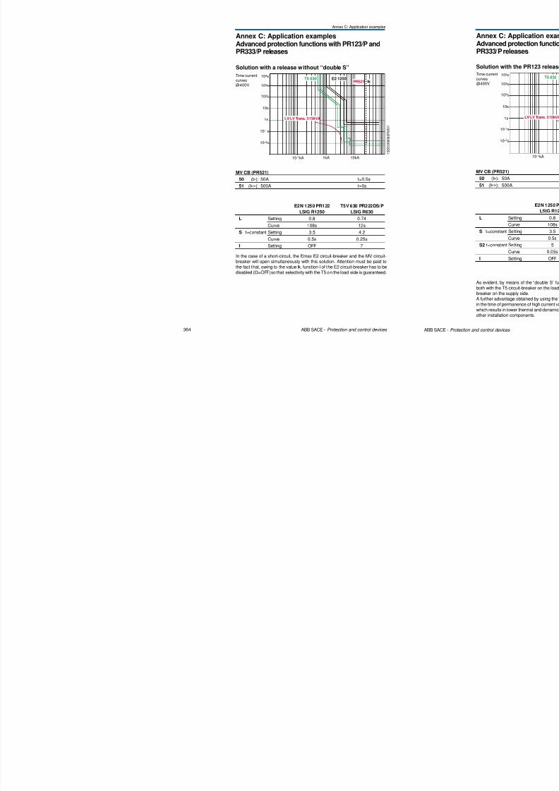
8/3/2019 ABB Electrical Install Ti On Handbook 4th Edition
http://slidepdf.com/reader/full/abb-electrical-install-ti-on-handbook-4th-edition 151/322
296 ABB SACE - Protection and control devices
TMA
103
t [s]
10-1
I11
1
102
10-1
10-2
1,05 102
101
101
In=630 I3=7.5xIn
8/3/2019 ABB Electrical Install Ti On Handbook 4th Edition
http://slidepdf.com/reader/full/abb-electrical-install-ti-on-handbook-4th-edition 152/322
5 Special applications
5.2 Networks at particular frequencies
1 S D C 0 0 8 0 3 9 F 0 0 0 1
L N
Diagram B1
Configuration with three poles in series (without neutral connected to earth)
• Interruption for phase to neutral fault: 3 poles in series
• Interruption for phase to earth fault: not considered
(The installation method must be such as to make the probability of a second
earth fault negligible)
Diagram B2
Load
8/3/2019 ABB Electrical Install Ti On Handbook 4th Edition
http://slidepdf.com/reader/full/abb-electrical-install-ti-on-handbook-4th-edition 153/322
300 ABB SACE - Protection and control devices
L N
Load
Diagram B2
Configuration with three poles in series (with neutral connected to earth and
interrupted)• Interruption for phase to neutral fault: 3 poles in series
• Interruption for phase to earth fault: 2 poles in series
NL
Load
Diagram C
Configuration with three poles in series (with neutral connected to earth but not
interrupted)
• Interruption for phase to neutral fault: 3 poles in series• Interruption for phase to earth fault: 3 poles in series
8/3/2019 ABB Electrical Install Ti On Handbook 4th Edition
http://slidepdf.com/reader/full/abb-electrical-install-ti-on-handbook-4th-edition 154/322
5 Special applications
5.3 1000 Vdc and 1000 Vac networks
1 S D C 0 0 8 0 4 4 F
0 0 0 1
-+
Load
B) 2+2 poles in series (1000 Vdc)
It is assumed that the risk of a double earth fault in which the first fault is
downstream of the breaker on one polarity and the second is upstream of the
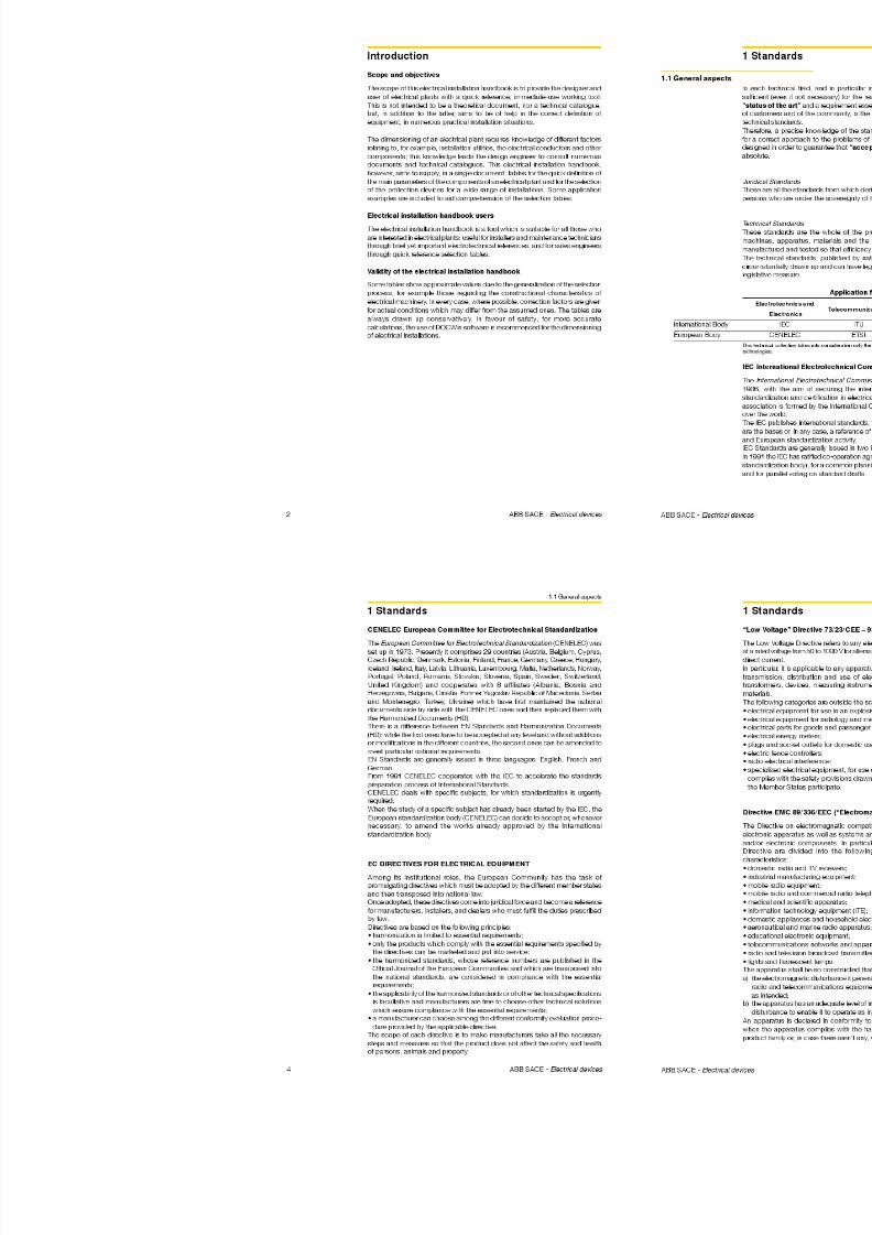
8/3/2019 ABB Electrical Install Ti On Handbook 4th Edition
http://slidepdf.com/reader/full/abb-electrical-install-ti-on-handbook-4th-edition 155/322
304 ABB SACE - Protection and control devices
1 S D C 0 0 8 0 4 5 F 0 0 0 1
-+
Load
same switching device on the opposite polarity is null.
In this condition the fault current, which can reach high values, effects only
some of the 4 poles necessary to ensure the breaking capacity.
It is possible to prevent the possibility of a double earth fault by installing a
device which signals the loss of insulation and identifies the position of the first
earth fault, allowing it to be eliminated quickly.
Networks with one polarity connected to earth
As the polarity connected to earth does not have to be interrupted (in the example
it is assumed that the polarity connected to earth is negative, although the
following is also valid with the polarity inverted), the diagram which shows the
connection of 4 poles in series on the polarity not connected to earth may be
used.
C) 4 poles in series (1000 Vdc)
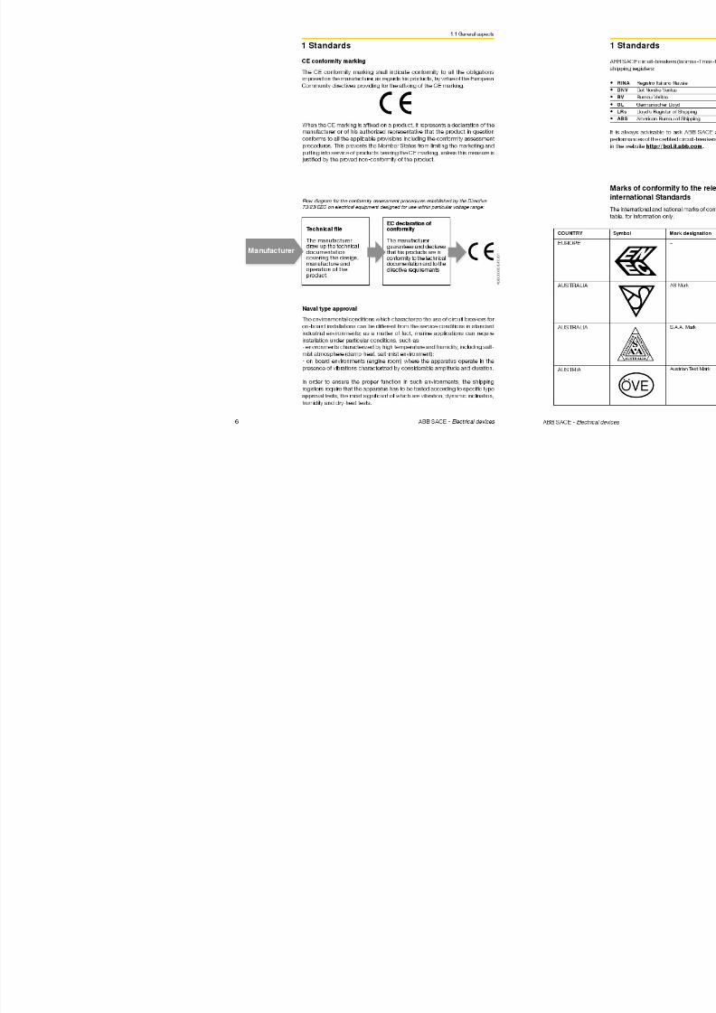
8/3/2019 ABB Electrical Install Ti On Handbook 4th Edition
http://slidepdf.com/reader/full/abb-electrical-install-ti-on-handbook-4th-edition 156/322
5 Special applications
5.3 1000 Vdc and 1000 Vac networks
Connection diagrams
Connection diagrams to be used according to the type of distribution systemfollow.
The risk of a double earth fault on different poles is assumed to be zero, that is,
the fault current involves only one part of the breaker poles.
Networks insulated from earth
The following diagrams may be used (the polarity may be inverted).
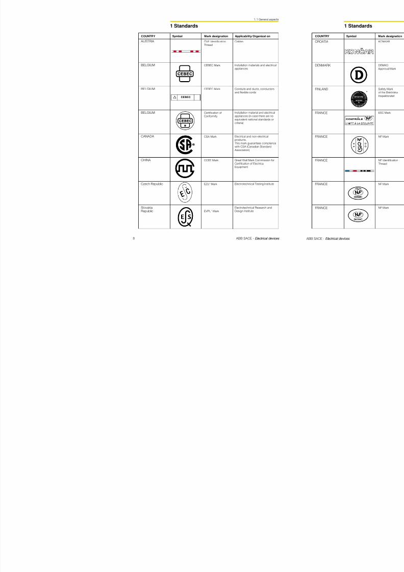
8/3/2019 ABB Electrical Install Ti On Handbook 4th Edition
http://slidepdf.com/reader/full/abb-electrical-install-ti-on-handbook-4th-edition 157/322
308 ABB SACE - Protection and control devices
1 S D C 0 0 8 0 4 7 F 0 0 0 1
-+
1 S D C 0 0 8 0 4 8 F 0 0 0 1
-+
Load
Load
E) 3+1 poles in series (1000 Vdc)
F) 2+2 poles in series (1000 Vdc)
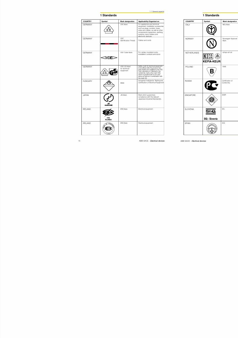
8/3/2019 ABB Electrical Install Ti On Handbook 4th Edition
http://slidepdf.com/reader/full/abb-electrical-install-ti-on-handbook-4th-edition 158/322
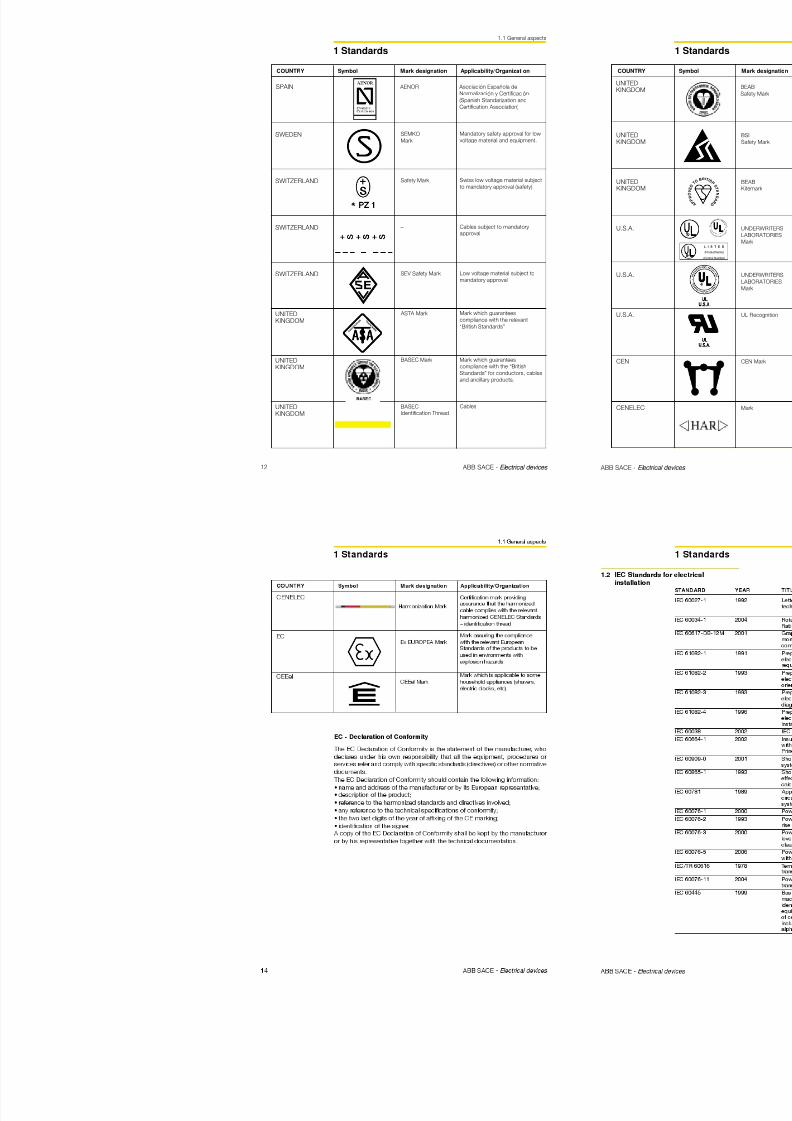
8/3/2019 ABB Electrical Install Ti On Handbook 4th Edition
http://slidepdf.com/reader/full/abb-electrical-install-ti-on-handbook-4th-edition 159/322
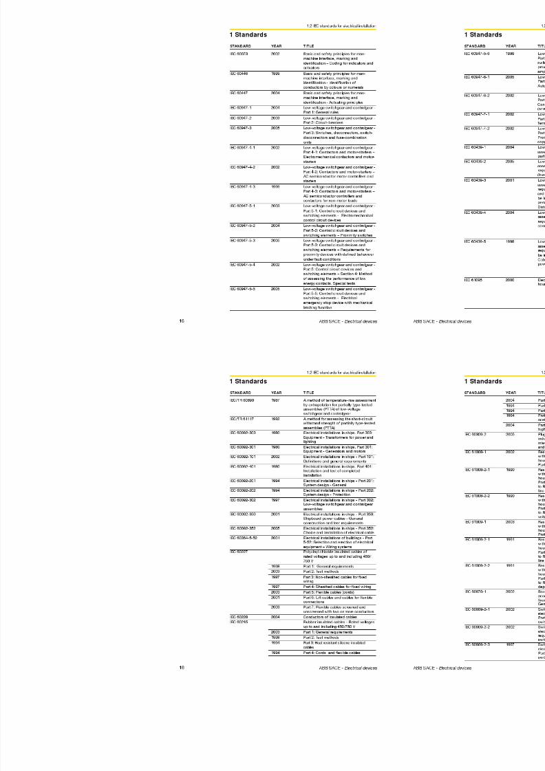
8/3/2019 ABB Electrical Install Ti On Handbook 4th Edition
http://slidepdf.com/reader/full/abb-electrical-install-ti-on-handbook-4th-edition 160/322
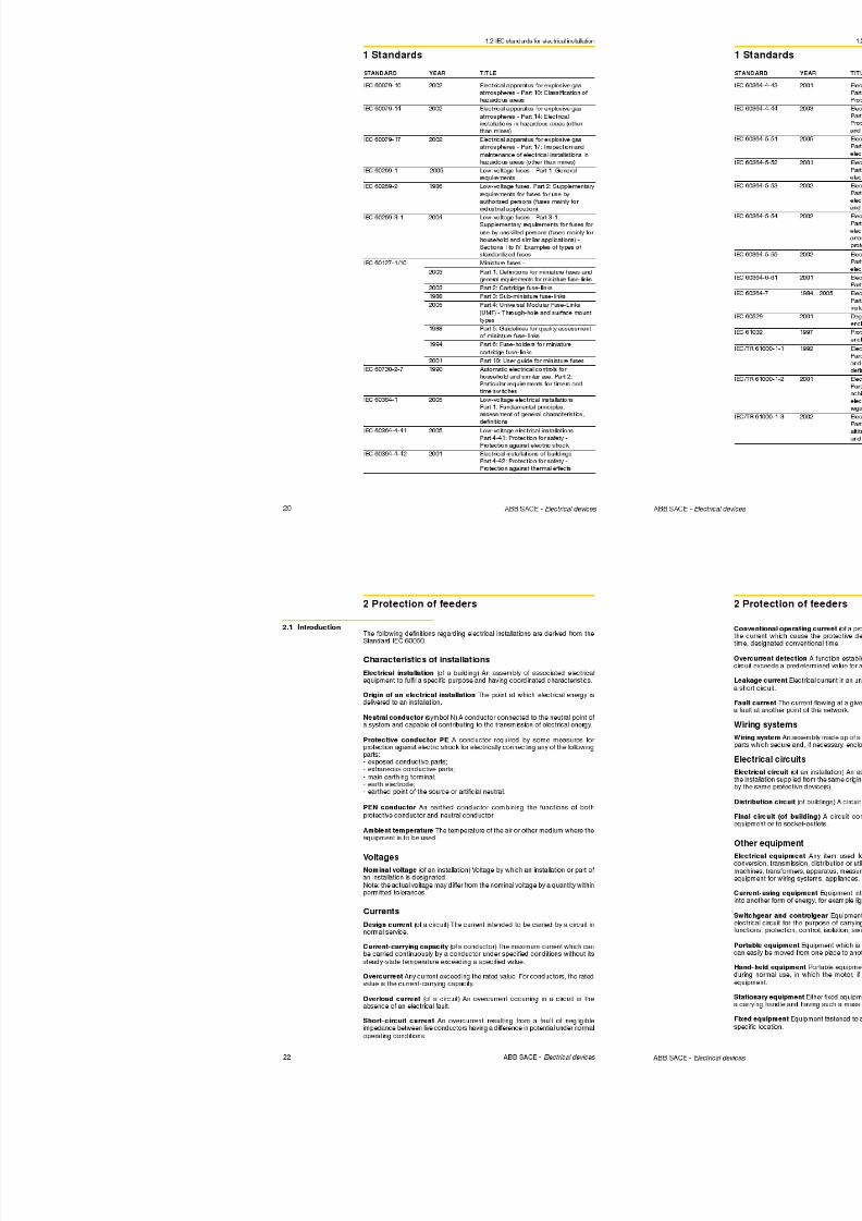
8/3/2019 ABB Electrical Install Ti On Handbook 4th Edition
http://slidepdf.com/reader/full/abb-electrical-install-ti-on-handbook-4th-edition 161/322
5 Special applications
5.4 Automatic transfer switches
Setting of parameters
All the parameters for the functioning of ATS010 can be simply adjusted through
dip-switches or trimmers.
Rated voltage for three-phase or single-phase plant
The following parameters of the N-Line can be set through dip-switches:
- network rated voltage value (from 100 V up to 500 V);- power supply type (three-phase or single-phase);
- frequency value (50 Hz or 60 Hz);
- type of strategy.
Note: Voltages higher than 500 V can be reached by using VTs (voltage
transformers); in this case the setting of the voltage value shall consider the
transformation ratio.
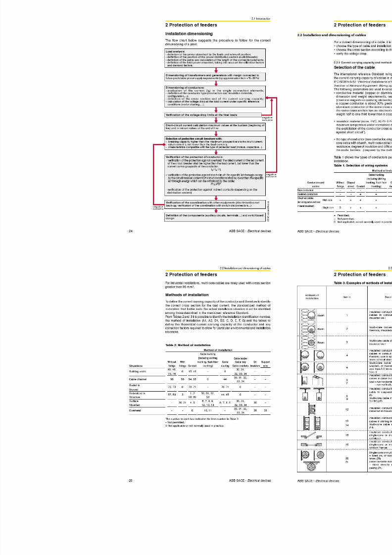
8/3/2019 ABB Electrical Install Ti On Handbook 4th Edition
http://slidepdf.com/reader/full/abb-electrical-install-ti-on-handbook-4th-edition 162/322
318 ABB SACE - Protection and control devices
1 S D C 0 0 8 0 5 2 F 0 0 0 1
OFF
100V
ON
4
3
2
1
OFF
115V
ON
4
3
2
1
OFF
120V
ON
4
3
2
1
OFF
208V
ON
4
3
2
1
The figure below shows all the possible voltage values which can be set by the
dip-switches from 1 to 4.
5 Special applications
5.4 Automatic transfer switches
Overvoltage threshold
According to the load characteristics, it is possible to set the voltage range
outside which the N-Line supply cannot be accepted and switching to the E-
Line is necessary.
8 0 5 3 F 0 0 0 1
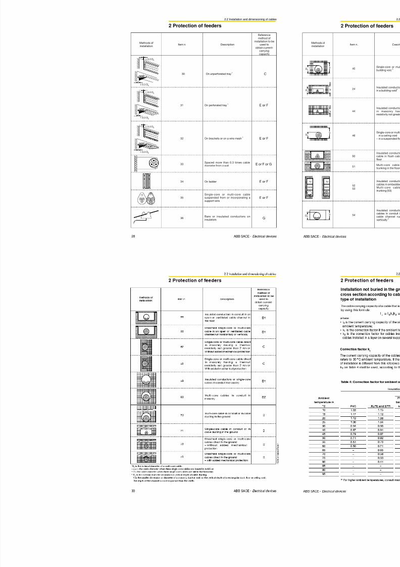
8/3/2019 ABB Electrical Install Ti On Handbook 4th Edition
http://slidepdf.com/reader/full/abb-electrical-install-ti-on-handbook-4th-edition 163/322
320 ABB SACE - Protection and control devices
1 S D C 0 0 8
1 S D C 0 0 8 0 5 4 F 0 0 0 1
1 S D C 0 0 8 0 5 5 F 0 0 0 1
Transfer switch delay configuration
Transfer switch delays can be set through special trimmers. Setting times and
relevant purposes are reported below:
T1 = 0 ÷ 32 s CB-N open
Delay time from net anomaly detection to N-Line CB opening. It is used to
avoid transfer switching in case of short voltage dips.
T2 = 0 ÷ 32 s GEN-SET START
Delay time from net anomaly detection to Gen set start command. It is used toprevent from transfer switching in case of short voltage dips.
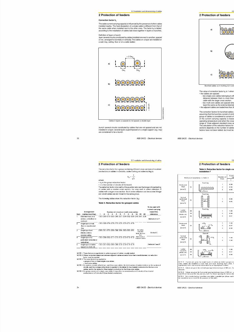
8/3/2019 ABB Electrical Install Ti On Handbook 4th Edition
http://slidepdf.com/reader/full/abb-electrical-install-ti-on-handbook-4th-edition 164/322
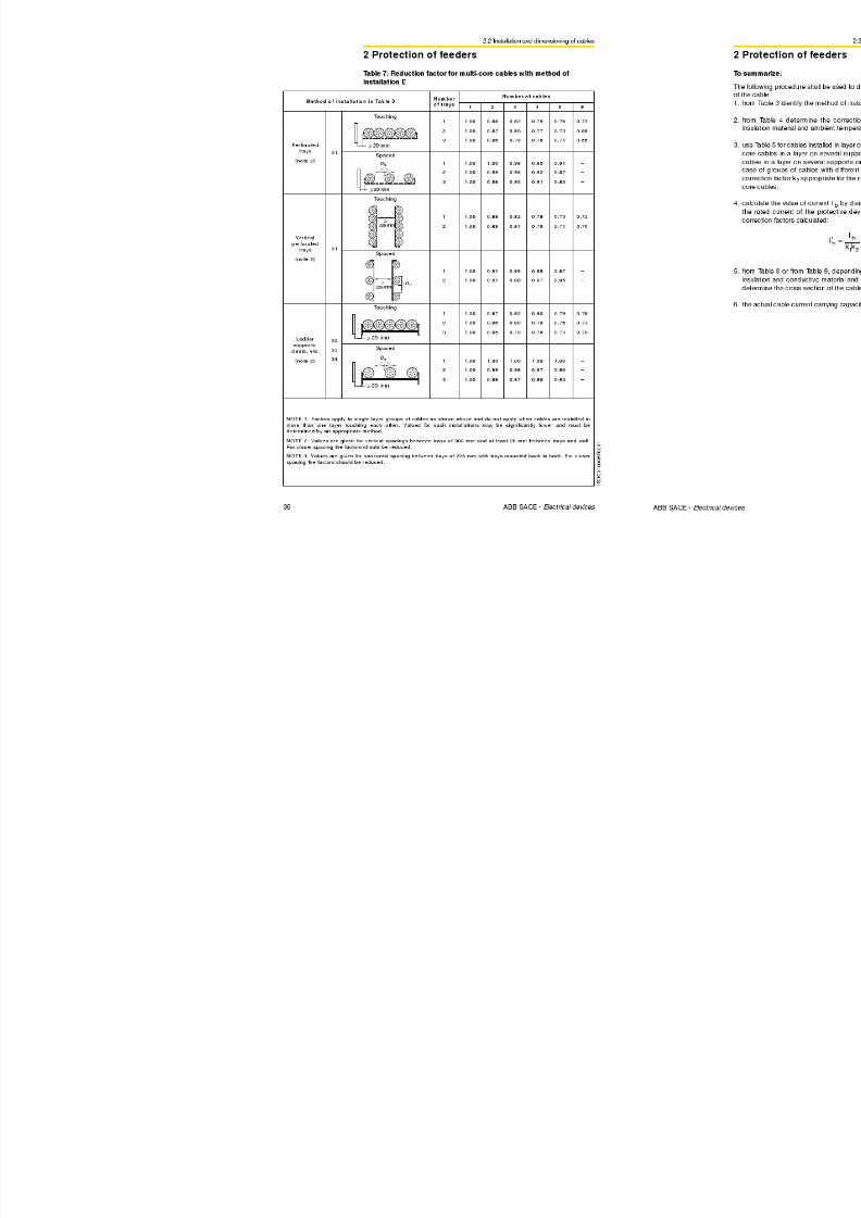
8/3/2019 ABB Electrical Install Ti On Handbook 4th Edition
http://slidepdf.com/reader/full/abb-electrical-install-ti-on-handbook-4th-edition 165/322
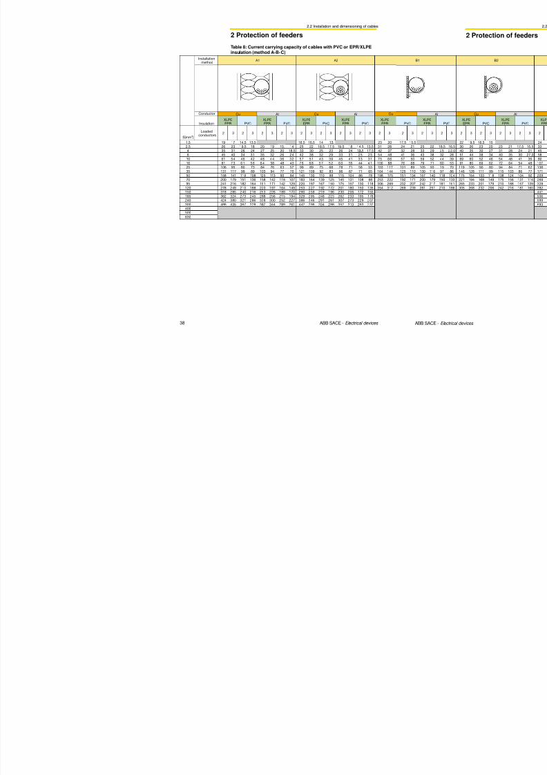
8/3/2019 ABB Electrical Install Ti On Handbook 4th Edition
http://slidepdf.com/reader/full/abb-electrical-install-ti-on-handbook-4th-edition 166/322
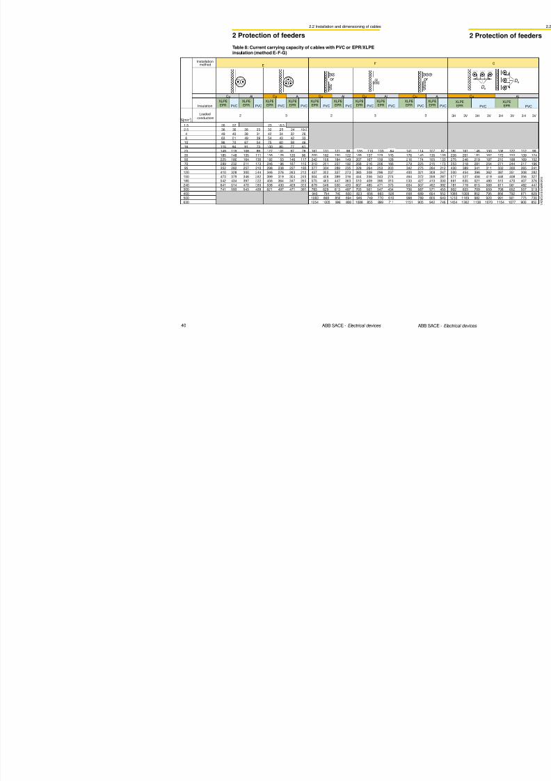
8/3/2019 ABB Electrical Install Ti On Handbook 4th Edition
http://slidepdf.com/reader/full/abb-electrical-install-ti-on-handbook-4th-edition 167/322
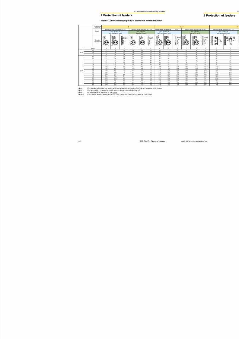
8/3/2019 ABB Electrical Install Ti On Handbook 4th Edition
http://slidepdf.com/reader/full/abb-electrical-install-ti-on-handbook-4th-edition 168/322
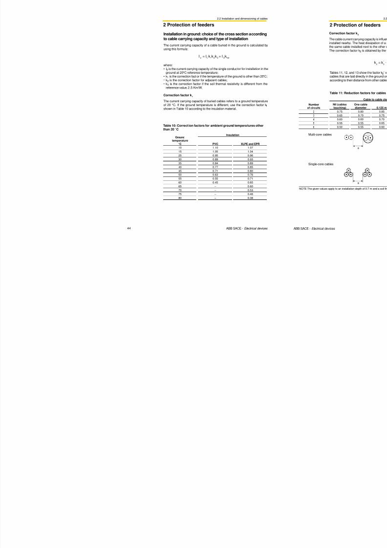
8/3/2019 ABB Electrical Install Ti On Handbook 4th Edition
http://slidepdf.com/reader/full/abb-electrical-install-ti-on-handbook-4th-edition 169/322
6.3 ArTu distribution switchboards
6 Switchboards
ArTu PB Series (Panelboard and Pan Assembly)
The ArTu line is now upgraded with the new ArTu PB Panelboard solution.The ArTu PB Panelboard is suitable for distribution applications with an incomerup to 800A and outgoing feeders up to 250A.The ArTu PB Panelboard is extremely sturdy thanks to its new designed
framework and it is available both in the wall-mounted version as well as in thefloor-mounted one.
ArTu PB Panelboard customisation is extremely flexible due to the smart designbased on configurations of 6, 12 and 18 outgoing ways and to the new ABBplug-in system that allows easy and fast connections for all T1 and T3 versions.Upon request, extension boxes are available on all sides of the structure, for
metering purposes too.The vertical trunking system is running behind the MCCB’s layer allowing easyaccess to every accessory wiring (SR’s, UV’s, AUX contacts).The ArTu PB Panelboard, supplied as a standard with a blind door, is availablewith a glazed one as well.
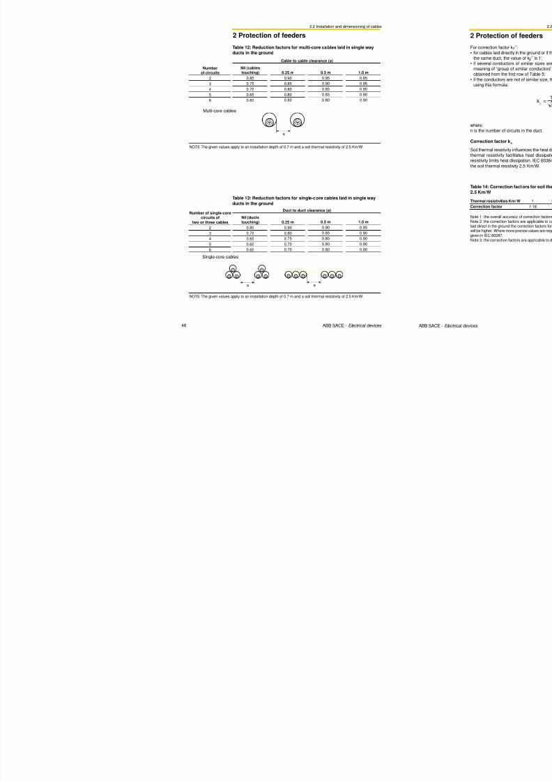
8/3/2019 ABB Electrical Install Ti On Handbook 4th Edition
http://slidepdf.com/reader/full/abb-electrical-install-ti-on-handbook-4th-edition 170/322
334 ABB SACE - Protection and control devices
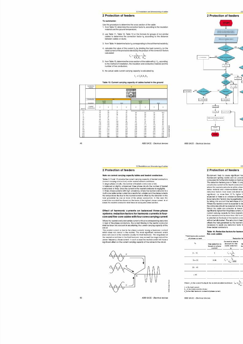
8/3/2019 ABB Electrical Install Ti On Handbook 4th Edition
http://slidepdf.com/reader/full/abb-electrical-install-ti-on-handbook-4th-edition 171/322
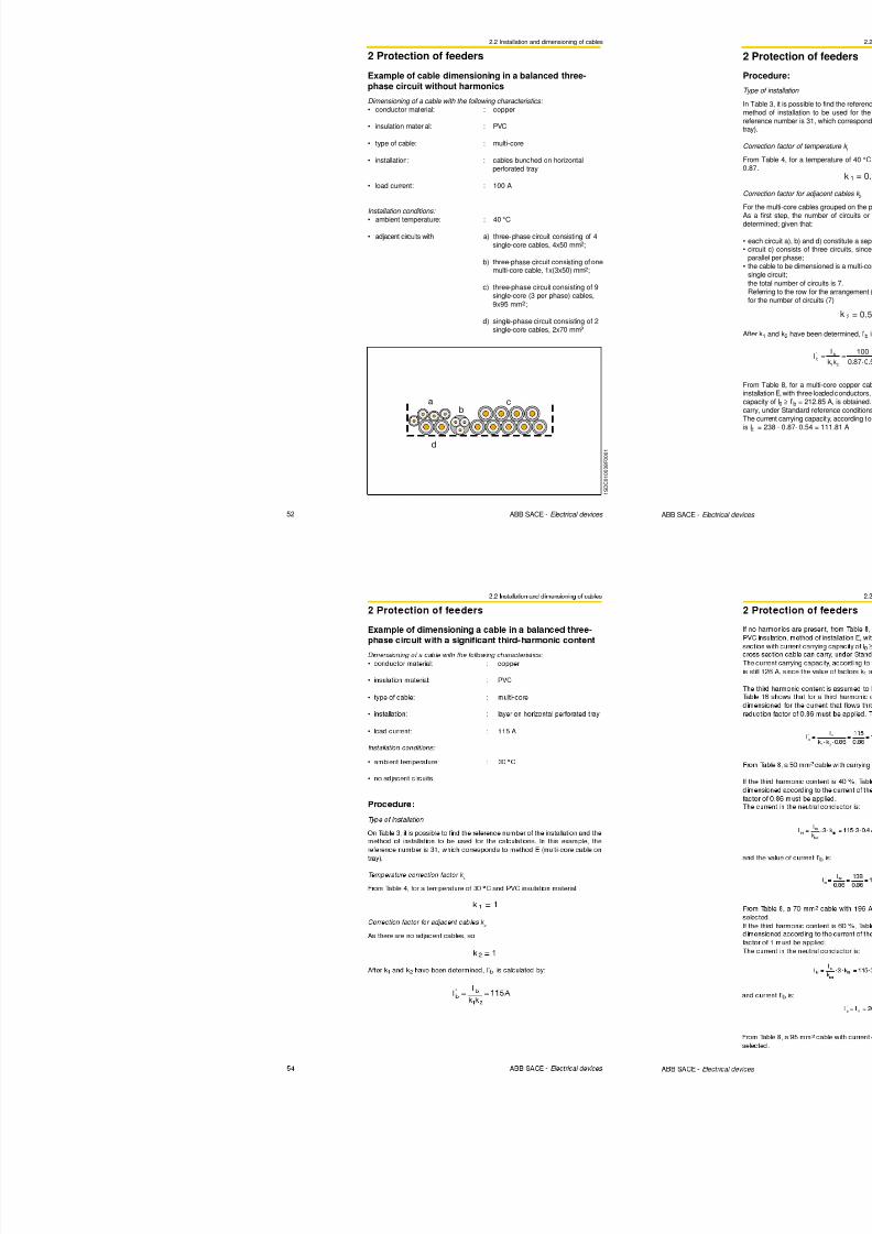
8/3/2019 ABB Electrical Install Ti On Handbook 4th Edition
http://slidepdf.com/reader/full/abb-electrical-install-ti-on-handbook-4th-edition 172/322

8/3/2019 ABB Electrical Install Ti On Handbook 4th Edition
http://slidepdf.com/reader/full/abb-electrical-install-ti-on-handbook-4th-edition 173/322
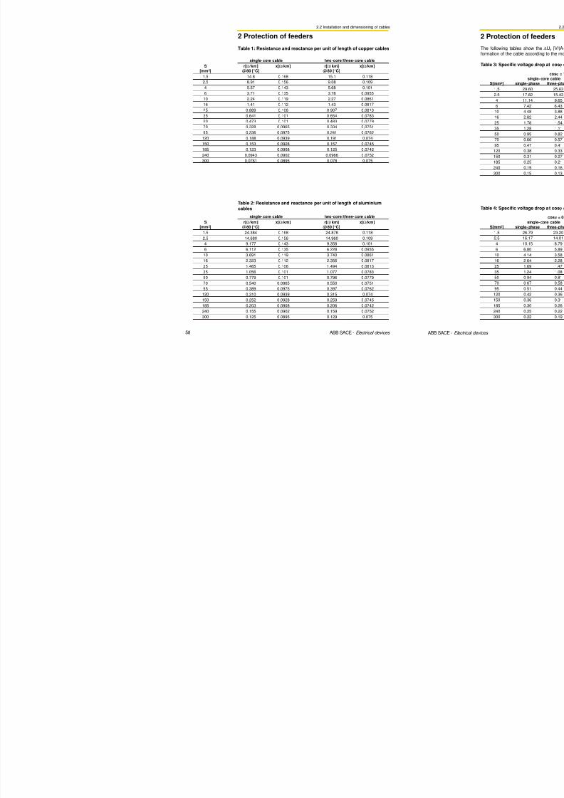
8/3/2019 ABB Electrical Install Ti On Handbook 4th Edition
http://slidepdf.com/reader/full/abb-electrical-install-ti-on-handbook-4th-edition 174/322
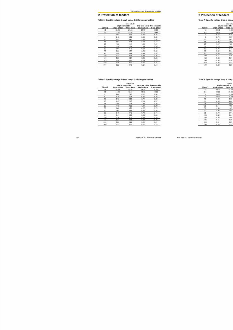
8/3/2019 ABB Electrical Install Ti On Handbook 4th Edition
http://slidepdf.com/reader/full/abb-electrical-install-ti-on-handbook-4th-edition 175/322
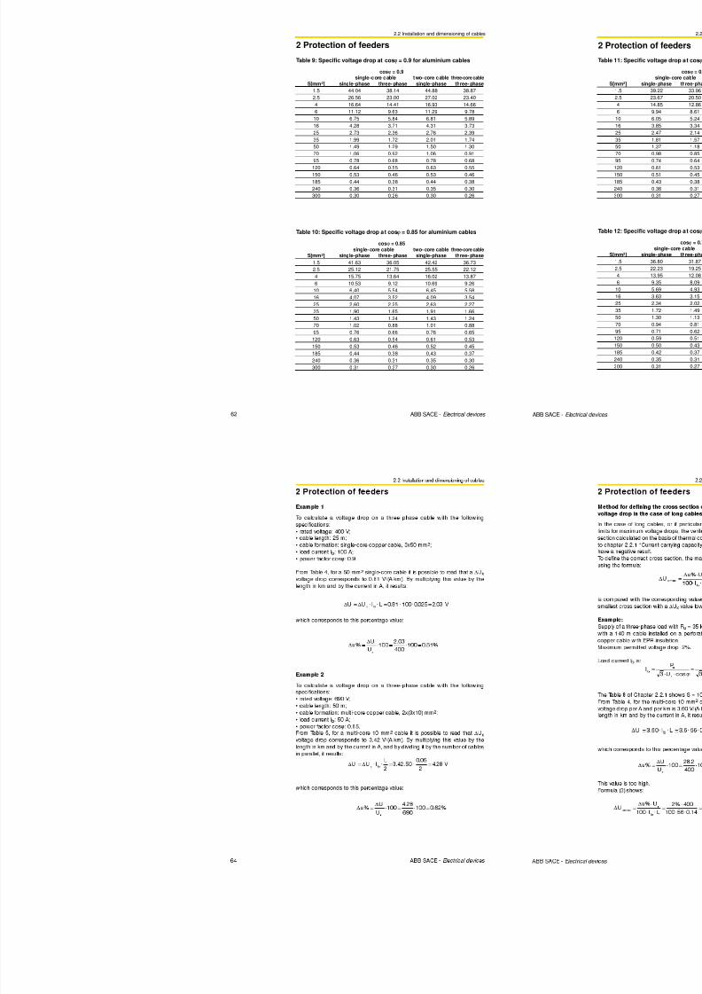
8/3/2019 ABB Electrical Install Ti On Handbook 4th Edition
http://slidepdf.com/reader/full/abb-electrical-install-ti-on-handbook-4th-edition 176/322
Annex B: Temperature rise evaluationaccording to IEC 60890
Annex B: temperature rise evaluation
Where enclosures without vertical partitions or individual sections have aneffective cooling surface greater than about 11.5 m or a width grater than about1.5 m, they should be divided for the calculation into fictitious sections, whosedimensions approximate to the foregoing values.
The following diagram shows the procedure to evaluate the temperature rise.
START
b (Tab.4)
Ae = (Ao. b)
Ae
> 1.25 mm2f =
h1.35
Ab
f =h1.35
Ab
yes no
∑
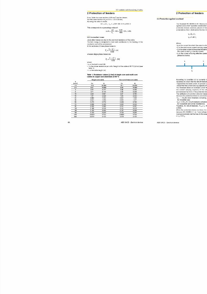
8/3/2019 ABB Electrical Install Ti On Handbook 4th Edition
http://slidepdf.com/reader/full/abb-electrical-install-ti-on-handbook-4th-edition 177/322
348 ABB SACE - Protection and control devices
withventilation openings?
c (Tab.10) d (Tab.6)
k (Tab.9)
x = 0.715
d (Tab.5)
k (Tab.7)
x = 0.804
c (Tab.8)
∆t0.5 = d . k
. Px
∆t1 = c . ∆t0.5
g =h
w
c (Tab.12) k (Tab.11)
x = 0.804
∆t0.5 = k . Px∆t0.75 = ∆t1 = c
.∆t0.5
yes no
1 S D C 0 0 8 0 4 3 F 0 2 0 1
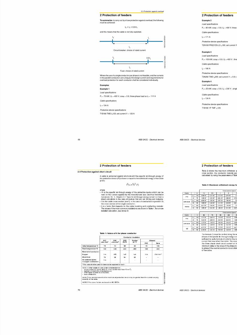
8/3/2019 ABB Electrical Install Ti On Handbook 4th Edition
http://slidepdf.com/reader/full/abb-electrical-install-ti-on-handbook-4th-edition 178/322
Annex B: Temperature rise evaluationaccording to IEC 60890
Annex B: temperature rise evaluation
Table 11: Enclosure constant k for enclosures without ventilation openingsand with an effective cooling surface A
e ≤ 1.25 m2
Ae [m2] k Ae [m2] k
0.08 3.973 0.65 0.848
0.09 3.643 0.7 0.803
0.1 3.371 0.75 0.764
0.15 2.5 0.8 0.728
0.2 2.022 0.85 0.696
0.25 1.716 0.9 0.668
0.3 1.5 0.95 0.641
0.35 1.339 1 0.618
0.4 1.213 1.05 0.596
0.45 1.113 1.1 0.576
0.5 1.029 1.15 0.557
0.55 0.960 1.2 0.540
0.6 0.9 1.25 0.524
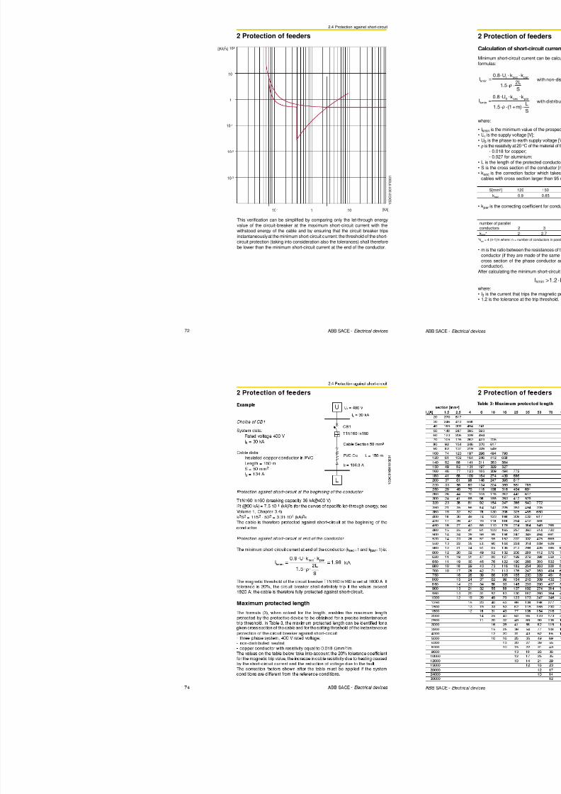
8/3/2019 ABB Electrical Install Ti On Handbook 4th Edition
http://slidepdf.com/reader/full/abb-electrical-install-ti-on-handbook-4th-edition 179/322
352 ABB SACE - Protection and control devices
Table 12: Temperature distribution factor c for enclosures without ventilation
openings and with an effective cooling surface Ae ≤ 1.25 m2
g c g c
0 1 1.5 1.231
0.1 1.02 1.6 1.237
0.2 1.04 1.7 1.24
0.3 1.06 1.8 1.244
0.4 1.078 1.9 1.246
0.5 1.097 2 1.249
0.6 1.118 2.1 1.251
0.7 1.137 2.2 1.253
0.8 1.156 2.3 1.254
0.9 1.174 2.4 1.255
1 1.188 2.5 1.256
1.1 1.2 2.6 1.257
1.2 1.21 2.7 1.258
1.3 1.22 2.8 1.259
1.4 1.226
where g is the ratio of the height and the width of the enclosure.
Annex B: Temperature rise evaluation
according to IEC 60890
Annex B: temperature rise evaluation
Example
H d l f t t i l ti f it hb d ith
Table 14: Emax power losses
X1-BN X1-L E1B-N E2B-N-S E2L E3N-S-H-V E3L E4S-H-V E6H-VF W F W F W F W F W F W F W F W F W
In=630 31 60 61 9 0
In=800 51 104 99 145 6 5 95 29 53 22 3 6
In=1000 79 162 155 227 96 147 45 83 38 58
In=1250 124 293 242 354 150 230 70 130 105 165 60 90
In=1600 209 415 253 378 115 215 170 265 85 150
In=2000 180 330 130 225 215 330
In=2500 205 350 335 515
In=3200 330 570 235 425 170 290
In=4000 360 660 265 445
In=5000 415 700
In=6300 650 1100
Total (3/4 poles)power loss in W
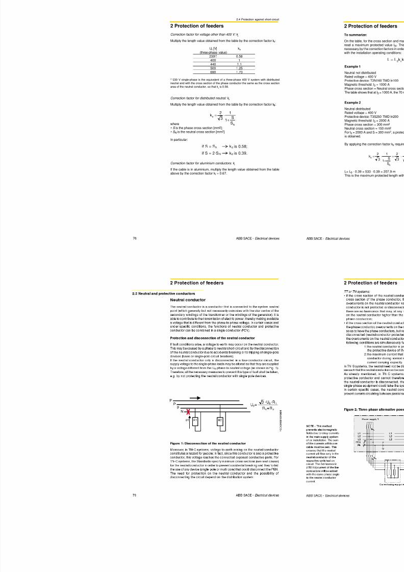
8/3/2019 ABB Electrical Install Ti On Handbook 4th Edition
http://slidepdf.com/reader/full/abb-electrical-install-ti-on-handbook-4th-edition 180/322
354 ABB SACE - Protection and control devices
Hereunder an example of temperature rise evaluation for a switchboard withthe following characteristics:- enclosure without ventilation openings- no internal segregation- separate enclosure for wall-mounting- one main circuit-breaker- 5 circuit-breakers for load supply- busbars and cable systems
IG
I1 I2 I3 I4 I5
H
D
W
Enclosure Circuit diagram
Dimensions [mm]
Height
2000
Width
1440
Depth
840
Number of horizontalpartitions = 0
Separate enclosurefor wall-mounting
I1
I2
I3
I4
I5
IG
A
B
C
D
E
F
Annex B: Temperature rise evaluation
according to IEC 60890
Annex B: temperature rise evaluation
Cables Cross-section Length Ib Power losses[n]xmm2 [m] [A] [W]
IG 4x240 1.0 1340 133.8
I1 240 2.0 330 64.9
I2 240 1.7 330 55.2
I3 240 1.4 330 45.4
I4 120 1.1 175 19
I5 120 0.8 175 13.8
Total power loss of cables [W] 332
For the cables connecting the circuit-breakers to the supply and the loads, the
power losses are calculated as , with In and Pn
given in the Table 4.
Here below the power losses for each connection:
Thus, the total power loss inside the enclosure is: P = 784 [W]
From the geometrical dimensions of the switchboard, the effective cooling
Ib
InP = Pn ( )2
⋅ (3 ⋅ Length)
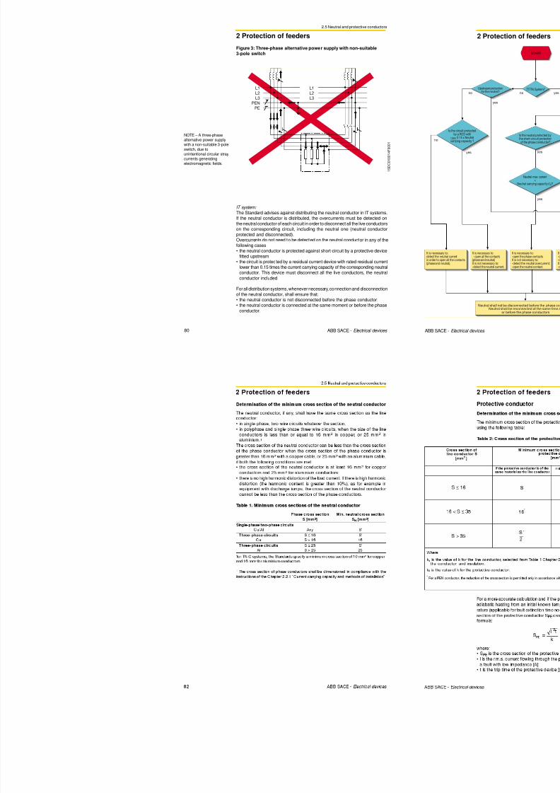
8/3/2019 ABB Electrical Install Ti On Handbook 4th Edition
http://slidepdf.com/reader/full/abb-electrical-install-ti-on-handbook-4th-edition 181/322
356 ABB SACE - Protection and control devices
Dimensions[m]x[m] A0[m2] b factor A0
Top 0.840x1.44 1.21 1.4 1.69
Front 2x1.44 1.64 0.9 2.59
Rear 2x1.44 1.64 0.5 1.44
Left-hand side 2x0.840 1.68 0.9 1.51
Right-hand side 2x0.840 1.68 0.9 1.51
Ae=Σ(A0⋅b) 8.75
Making reference to the procedure described in the diagram at page 348, it is
possible to evaluate the temperature rise inside the switchboard.
From the geometrical dimensions of the switchboard, the effective coolingsurface Ae is determined below:
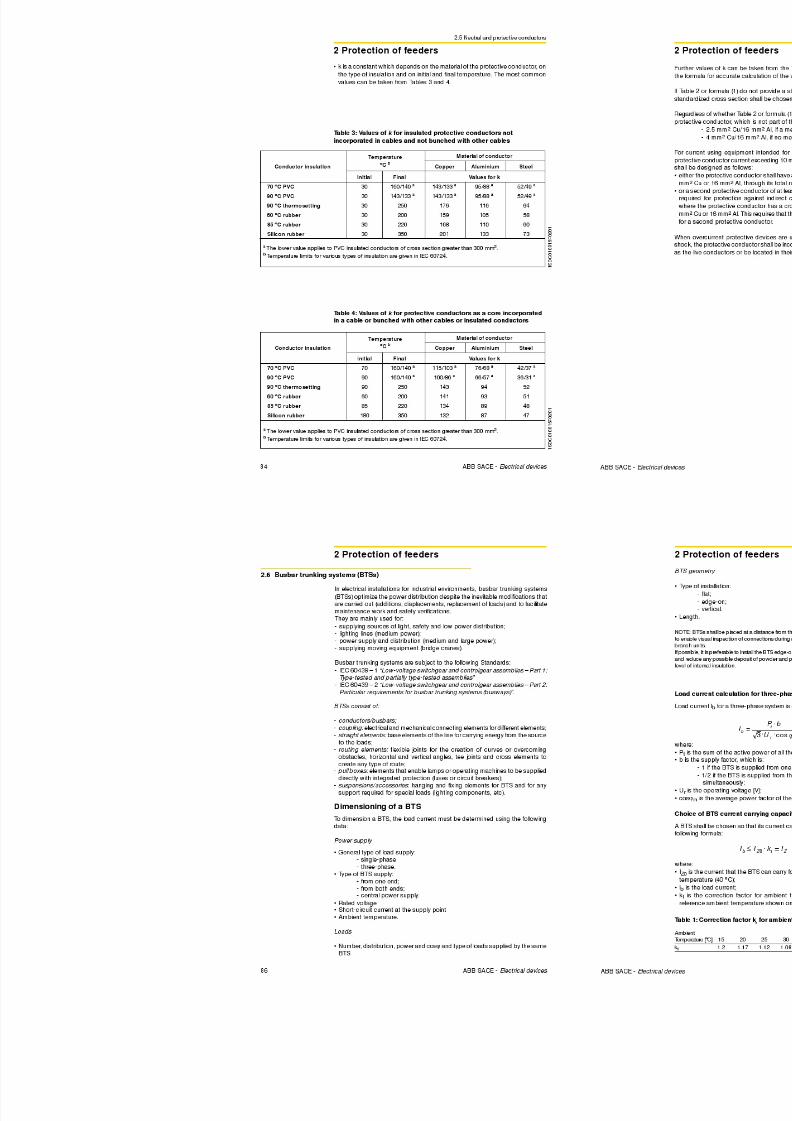
8/3/2019 ABB Electrical Install Ti On Handbook 4th Edition
http://slidepdf.com/reader/full/abb-electrical-install-ti-on-handbook-4th-edition 182/322
Annex C: Application examplesAdvanced protection functions with PR123/P andPR333/P releases
Annex C: Application examples
Double GThe Emax type circuit-breakers, equipped with the PR123 and PR333 electronicreleases, allow two independent curves for protection G:-one for the internal protection (function G without external toroid);
-one for the external protection (function G with external toroid)
A typical application of function double G consists in simultaneous protectionboth against earth fault of the secondary of the transformer and of its connectioncables to the circuit-breaker terminals (restricted earth fault protect ion), as well
as against earth faults on the load side of the circuit-breaker (outside therestricted earth fault protection).
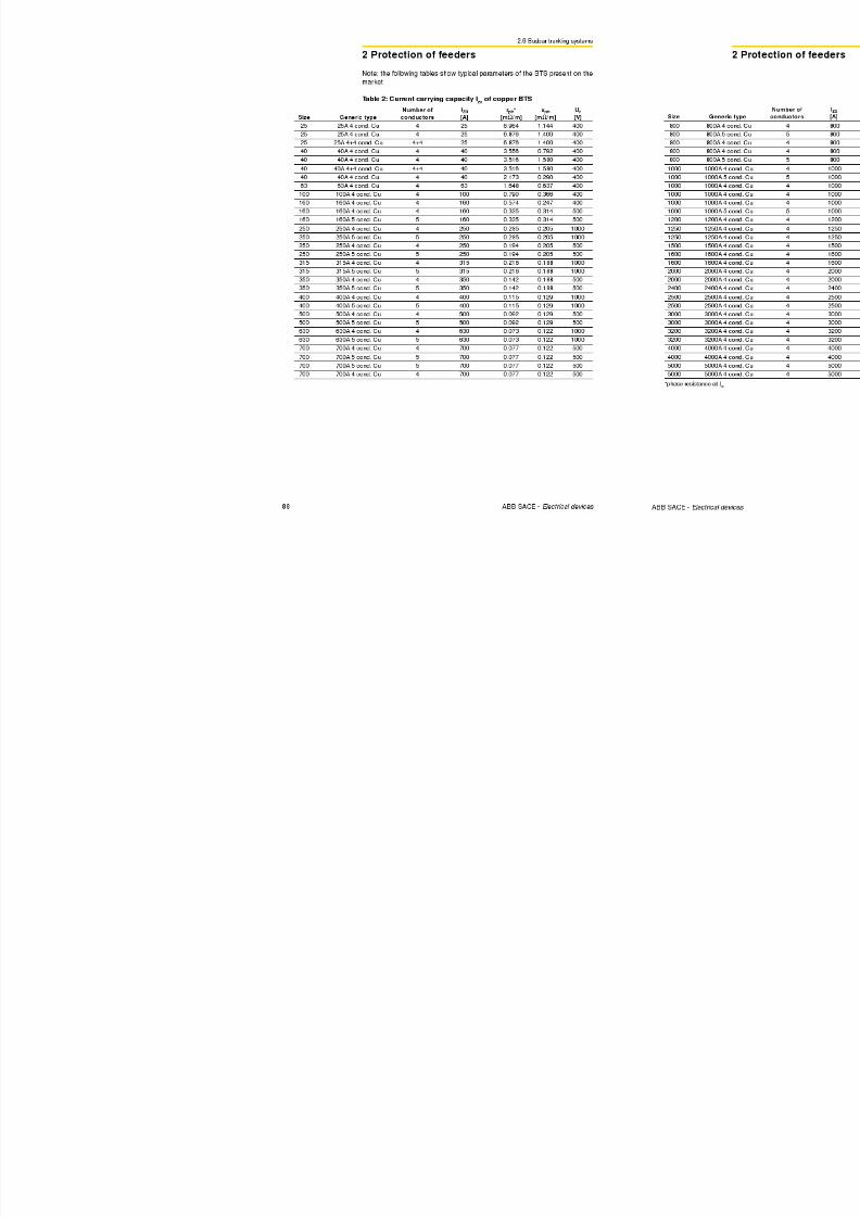
8/3/2019 ABB Electrical Install Ti On Handbook 4th Edition
http://slidepdf.com/reader/full/abb-electrical-install-ti-on-handbook-4th-edition 183/322
360 ABB SACE - Protection and control devices
1 S D C 0 0 8 0 5 0 F 0 2 0
1
Example:Figure 1 shows a fault on the load side of an Emax circuit-breaker: the faultcurrent flows through one phase only and, if the vectorial sum of the currentsdetected by the four current transformers (CTs) results to be higher than the setthreshold, the electronic release activates function G (and the circuit-breakertrips).
Figure 1
Trasformersecondary winding
Emaxinternal CTs
L1
L2
L3
N
PE
Annex C: Application examplesAdvanced protection functions with PR123/P andPR333/P releases
Annex C: Application examples
If, with the same configuration as Figure 3, the fault occurs on the load side ofthe Emax circuit-breaker, the fault current would affect both the toroid as wellas the current transformers on the phases. To define which circuit-breaker is to
trip (MV or LV circuit-breaker), suitable coordination of the trip times is required:in particular, it is necessary to set the times so that LV circuit-breaker
opening due to internal function G is faster than realization of the alarm signalcoming from the external toroid. Therefore, thanks to the time-currentdiscrimination between the two G protection functions, before the MV circuit-breaker on the primary of the transformer receives the trip command, the circuit-
breaker on the LV side is able to eliminate the earth fault.Obviously, if the fault occurred on the supply side of the LV circuit-breaker, onlythe circuit-breaker on the MV side would trip.
The table shows the main characteristics of the range of toroids (available only
in the c losed version).
Characteristics of the toroid ranges
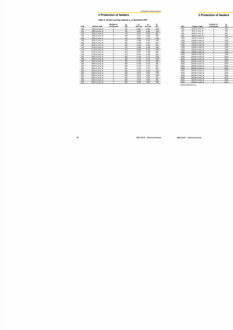
8/3/2019 ABB Electrical Install Ti On Handbook 4th Edition
http://slidepdf.com/reader/full/abb-electrical-install-ti-on-handbook-4th-edition 184/322
362 ABB SACE - Protection and control devices
Rated current
Outer dimensions of the tooid
DW
H
100 A, 250 A, 400 A, 800 A
W = 165 mm
D = 160 mm
H = 112 mm
Ø = 112 mmInternal diameter of the toroid
1 S D C 0 0 8 0 5 3
F 0 2 0 1
Characteristics of the toroid ranges
Annex C: Application examplesAdvanced protection functions with PR123/P andPR333/P releases
Annex C: Application examples
Solution with a release without “double S”
Time currentcurves@400V
1
S D C 0 0 8 0 8 3 F 0 0 0 1
10-2s
10-1s
1s
10s
102s
103s
1kA
104s
10-1kA 10kA
T5 630 E2 1250PR521 Ik
LV/LV Trans. 315kVA
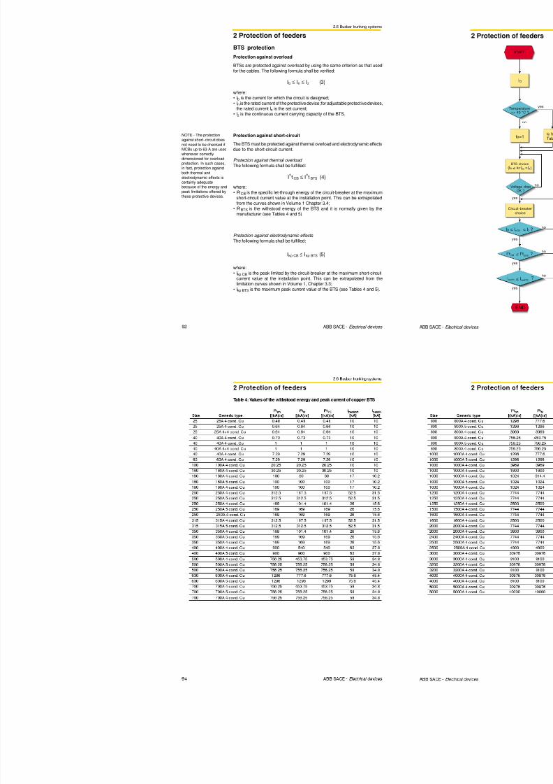
8/3/2019 ABB Electrical Install Ti On Handbook 4th Edition
http://slidepdf.com/reader/full/abb-electrical-install-ti-on-handbook-4th-edition 185/322
364 ABB SACE - Protection and control devices
In the case of a short-circuit, the Emax E2 circuit-breaker and the MV circuit-breaker will open simultaneously with this solution. Attention must be paid tothe fact that, owing to the value Ik, function I of the E2 circuit-breaker has to bedisabled (I3=OFF) so that selectivity with the T5 on the load side is guaranteed.
MV CB (PR521)
50 (I>): 50A t=0.5s
51 (I>>): 500A t=0s
E2N 1250 PR122 T5V 630 PR222DS/P
LSIG R1250 LSIG R630
L Setting 0.8 0.74
Curve 108s 12s
S t=constant Setting 3.5 4.2
Curve 0.5s 0.25s
I Setting OFF 7
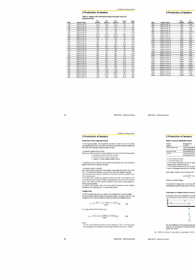
8/3/2019 ABB Electrical Install Ti On Handbook 4th Edition
http://slidepdf.com/reader/full/abb-electrical-install-ti-on-handbook-4th-edition 186/322
ABB SACE S.p.A.An ABB Group Company
L.V. Breakers
Via Baioni, 3524123 Bergamo - ItalyTel.: +39 035.395.111 - Telefax: +39 035.395.306-433
http://www.abb.com
Due to possible developments of standards as well as ofmaterials, the characteristics and dimensions specified in
this document may only be considered binding afterconfirmation by ABB SACE. 1 S D
C 0 0 8 0 0 1 D 0 2 0 4
0 3 / 0 6
P r i n
t e d
i n I t a l y
Electrical installation handbookVolume 2
1SDC010001D0204
Electrical devices4th edition
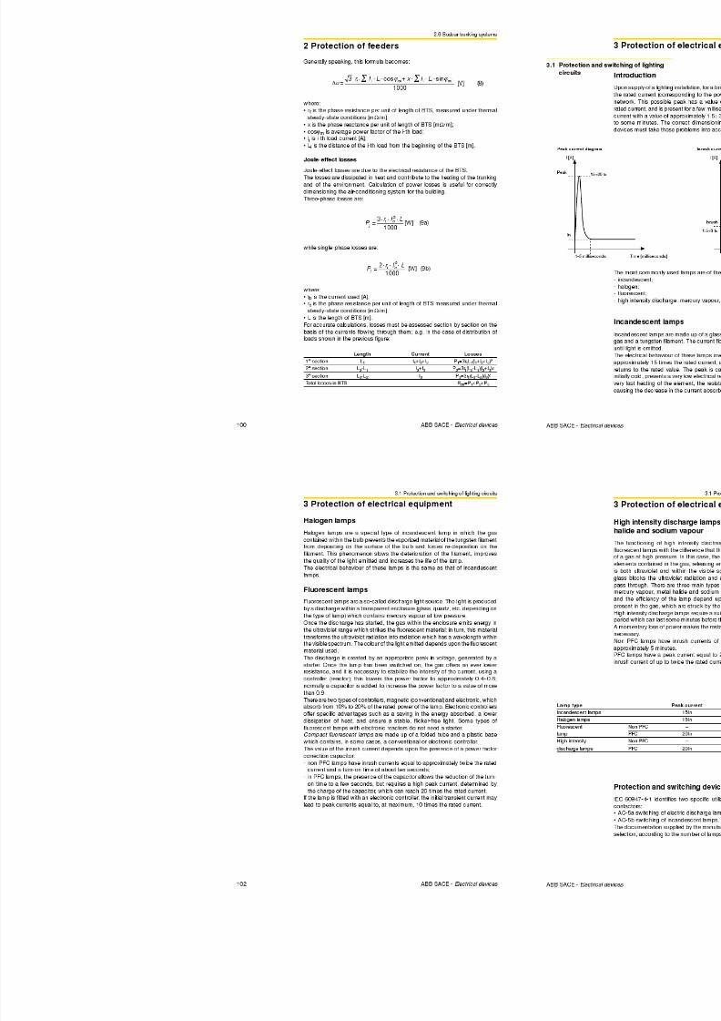
8/3/2019 ABB Electrical Install Ti On Handbook 4th Edition
http://slidepdf.com/reader/full/abb-electrical-install-ti-on-handbook-4th-edition 187/322
ABB SACE
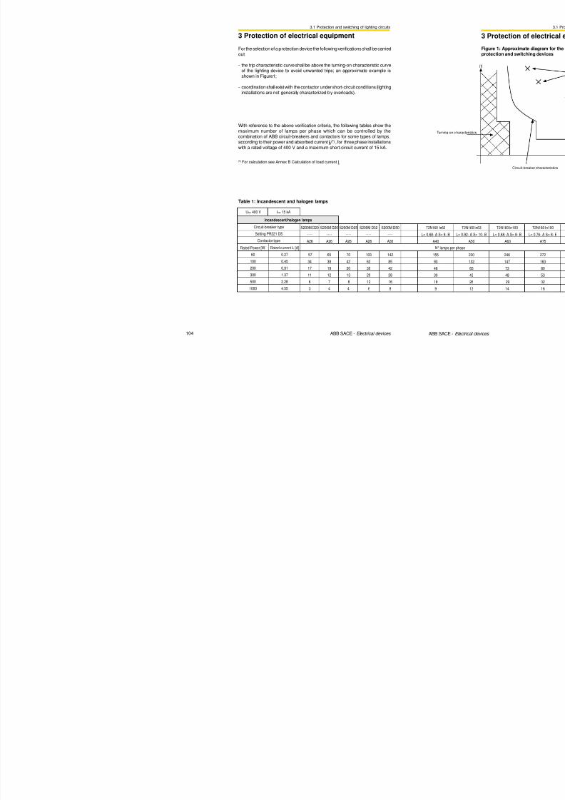
8/3/2019 ABB Electrical Install Ti On Handbook 4th Edition
http://slidepdf.com/reader/full/abb-electrical-install-ti-on-handbook-4th-edition 188/322

8/3/2019 ABB Electrical Install Ti On Handbook 4th Edition
http://slidepdf.com/reader/full/abb-electrical-install-ti-on-handbook-4th-edition 189/322
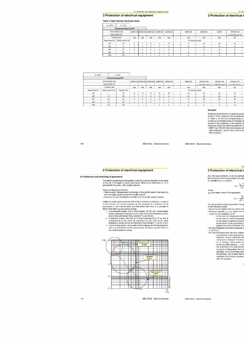
8/3/2019 ABB Electrical Install Ti On Handbook 4th Edition
http://slidepdf.com/reader/full/abb-electrical-install-ti-on-handbook-4th-edition 190/322
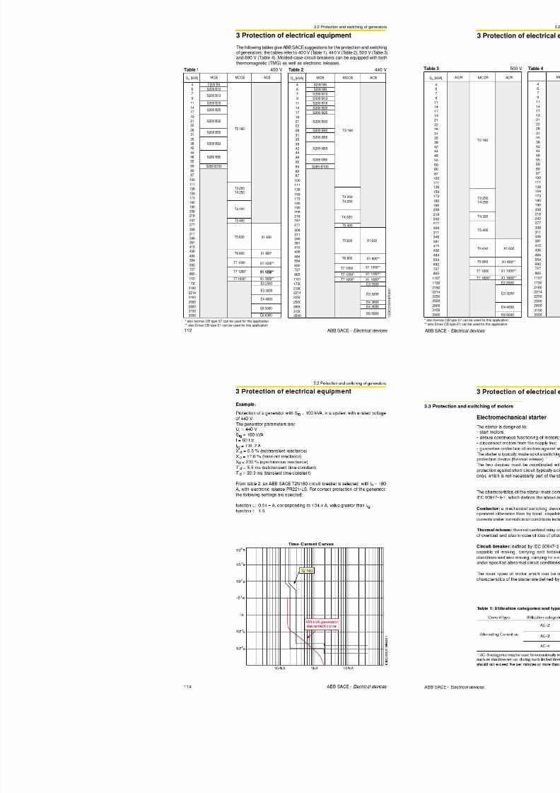
8/3/2019 ABB Electrical Install Ti On Handbook 4th Edition
http://slidepdf.com/reader/full/abb-electrical-install-ti-on-handbook-4th-edition 191/322
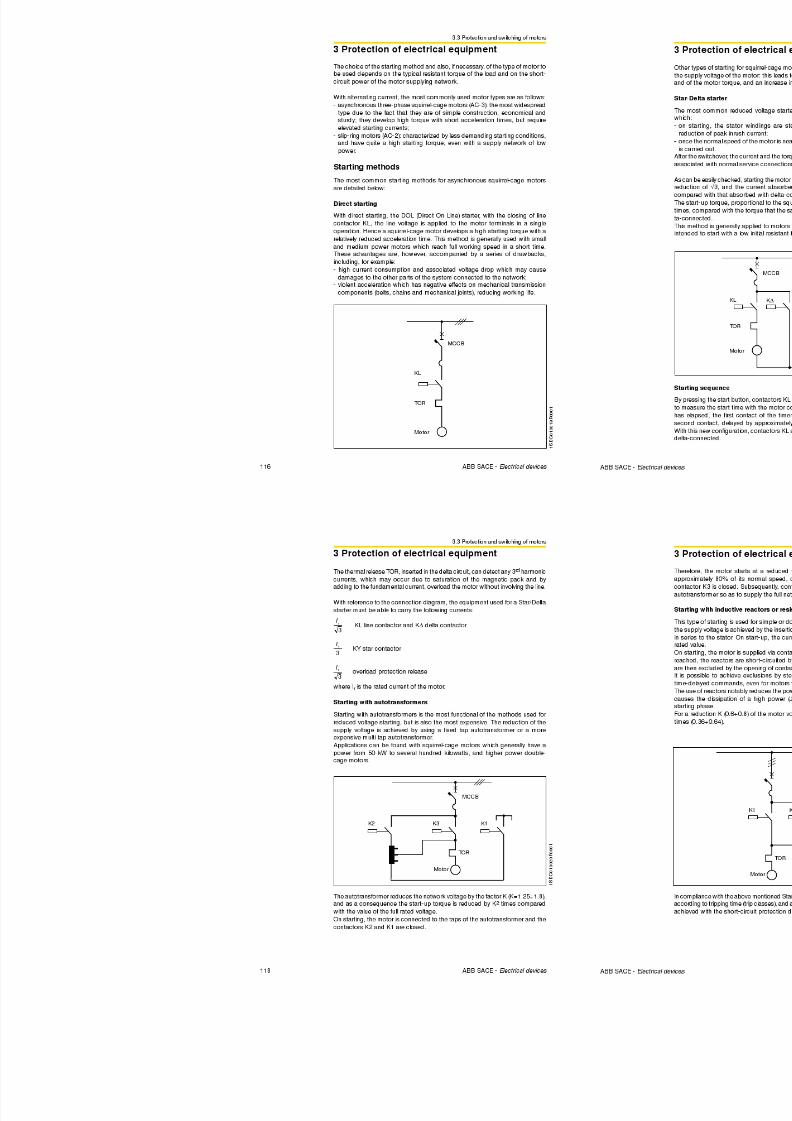
8/3/2019 ABB Electrical Install Ti On Handbook 4th Edition
http://slidepdf.com/reader/full/abb-electrical-install-ti-on-handbook-4th-edition 192/322
1.1 General aspects
1 Standards
COUNTRY Symbol Mark designation Applicability/Organization
AUSTRIA
BELGIUM
BELGIUM
BELGIUM
Ö VE Identification
Thread
CEBEC Mark
CEBEC Mark
Certification of Conformity
Cables
Installation materials and electrical
appliances
Conduits and ducts, conductors
and flexible cords
Installation material and electricalappliances (in case there are no
equivalent national standards or
criteria)

8/3/2019 ABB Electrical Install Ti On Handbook 4th Edition
http://slidepdf.com/reader/full/abb-electrical-install-ti-on-handbook-4th-edition 193/322
8 ABB SACE - Electrical devices
CANADA
CHINA
Czech Republic
SlovakiaRepublic
CSA Mark
CCEE Mark
EZU’ Mark
EVPU’ Mark
)
Electrical and non-electricalproducts.
This mark guarantees compliance
with CSA (Canadian Standard
Association)
Great Wall Mark Commission for
Certification of Electrical
Equipment
Electrotechnical Testing Institute
Electrotechnical Research and
Design Institute
1.1 General aspects
1 Standards
COUNTRY Symbol Mark designation Applicability/Organization
GERMANY
GERMANY
GERMANY
GERMANY
VDE Mark
VDE
Identification Thread
VDE Cable Mark
VDE-GS Markfor technical
equipment
For appliances and technical
equipment, installation accessories
such as plugs, sockets, fuses,
wires and cables, as well as other
components (capacitors, earthing
systems, lamp holders and
electronic devices)
Cables and cords
For cables, insulated cords,installation conduits and ducts
Safety mark for technical equipmentto be affixed after the product hasbeen tested and certified by the VDE
Test Laboratory in Offenbach; theconformity mark is the mark VDE,
üft
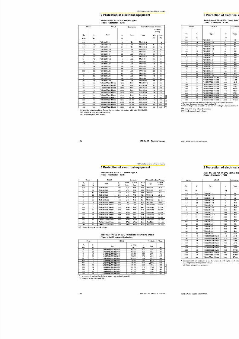
8/3/2019 ABB Electrical Install Ti On Handbook 4th Edition
http://slidepdf.com/reader/full/abb-electrical-install-ti-on-handbook-4th-edition 194/322
10 ABB SACE - Electrical devices
HUNGARY
JAPAN
IRELAND
IRELAND
MEEI
JIS Mark
IIRS Mark
IIRS Mark
y ,which is granted both to be usedalone as well as in combination withthe mark GS
Hungarian Institute for Testing andCertification of Electrical Equipment
Mark which guarantees
compliance with the relevant
Japanese Industrial Standard(s).
Electrical equipment
Electrical equipment
geprüfte Sicherheit
M A R K
O F CO N F O
R M
I T Y
I . I .R . S.
1.1 General aspects
1 Standards
COUNTRY Symbol Mark designation Applicability/Organization
SWEDEN
SWITZERLAND
SWITZERLAND
SEMKO
Mark
Safety Mark
–
Mandatory safety approval for low
voltage material and equipment.
Swiss low voltage material subject
to mandatory approval (safety).
Cables subject to mandatoryapproval
SPAIN AENOR Asociación Española de
Normalización y Certificación.
(Spanish Standarization and
Certification Association)
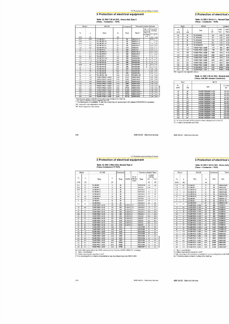
8/3/2019 ABB Electrical Install Ti On Handbook 4th Edition
http://slidepdf.com/reader/full/abb-electrical-install-ti-on-handbook-4th-edition 195/322
12 ABB SACE - Electrical devices
SWITZERLAND
UNITEDKINGDOM
UNITEDKINGDOM
UNITEDKINGDOM
SEV Safety Mark
ASTA Mark
BASEC Mark
BASECIdentification Thread
Low voltage material subject to
mandatory approval
Mark which guarantees
compliance with the relevant
“British Standards”
Mark which guarantees
compliance with the “British
Standards” for conductors, cables
and ancillary products.
Cables
C E R T
I F I C
A T I O N T R A D
E M A R K

8/3/2019 ABB Electrical Install Ti On Handbook 4th Edition
http://slidepdf.com/reader/full/abb-electrical-install-ti-on-handbook-4th-edition 196/322
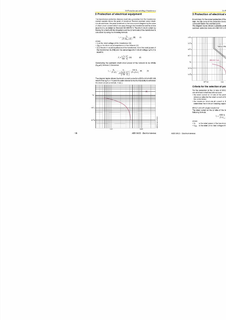
8/3/2019 ABB Electrical Install Ti On Handbook 4th Edition
http://slidepdf.com/reader/full/abb-electrical-install-ti-on-handbook-4th-edition 197/322
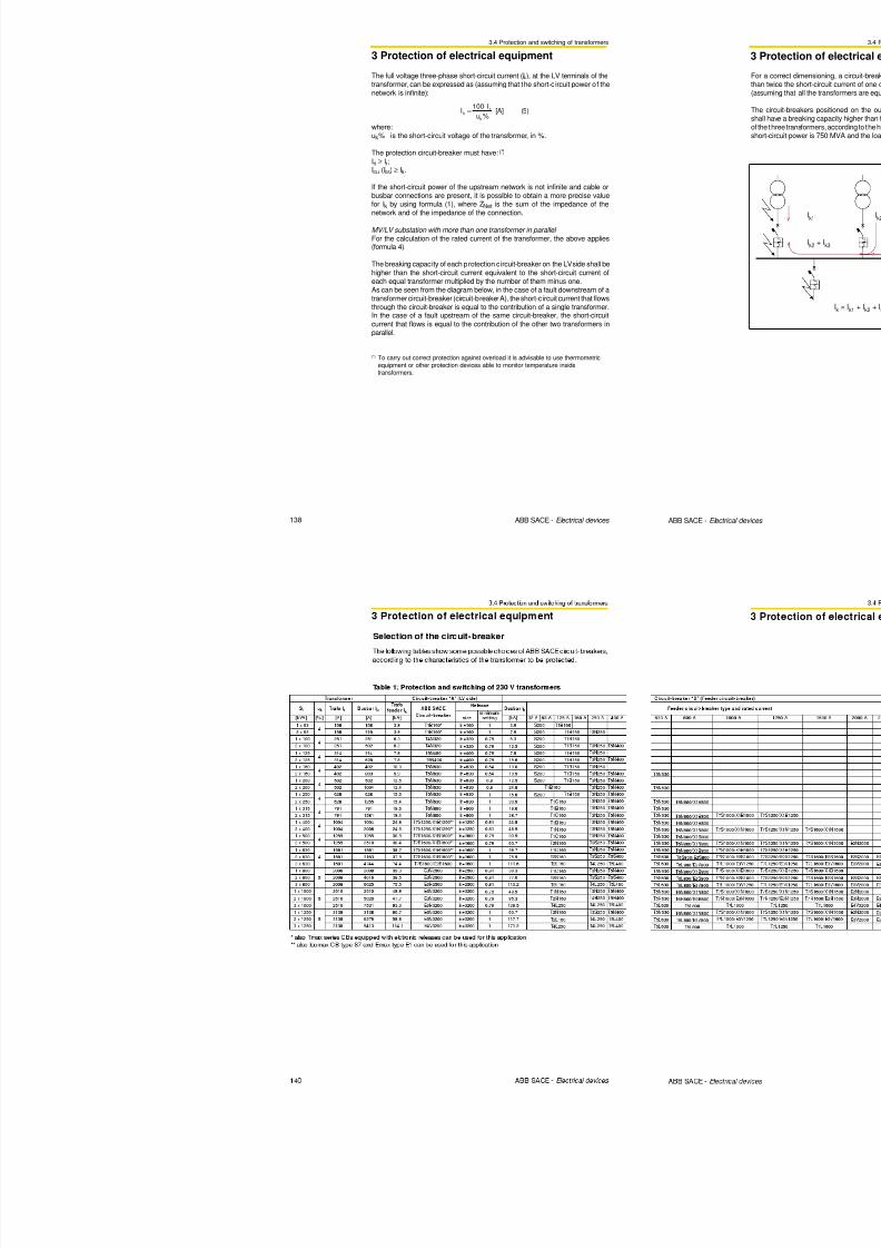
8/3/2019 ABB Electrical Install Ti On Handbook 4th Edition
http://slidepdf.com/reader/full/abb-electrical-install-ti-on-handbook-4th-edition 198/322
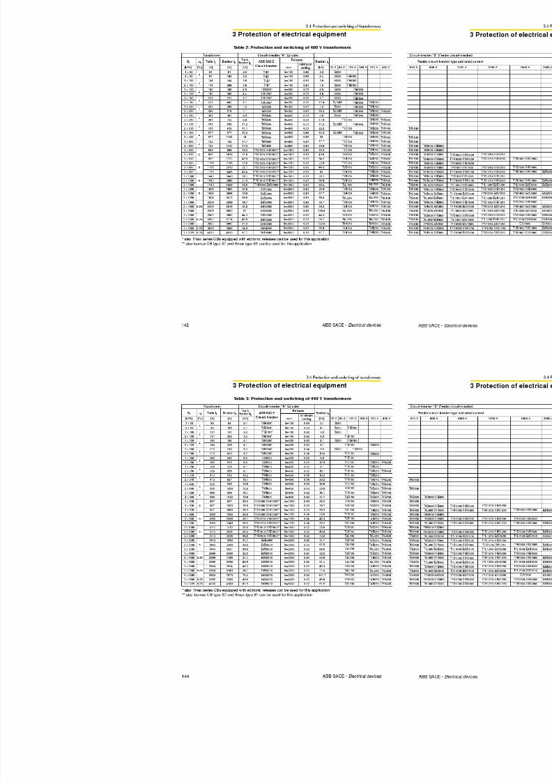
8/3/2019 ABB Electrical Install Ti On Handbook 4th Edition
http://slidepdf.com/reader/full/abb-electrical-install-ti-on-handbook-4th-edition 199/322
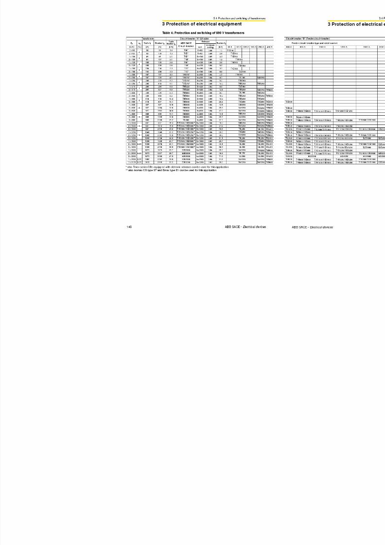
8/3/2019 ABB Electrical Install Ti On Handbook 4th Edition
http://slidepdf.com/reader/full/abb-electrical-install-ti-on-handbook-4th-edition 200/322
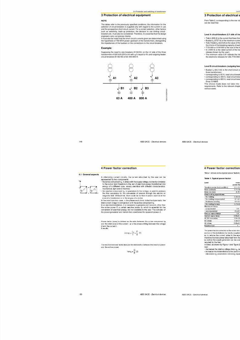
8/3/2019 ABB Electrical Install Ti On Handbook 4th Edition
http://slidepdf.com/reader/full/abb-electrical-install-ti-on-handbook-4th-edition 201/322
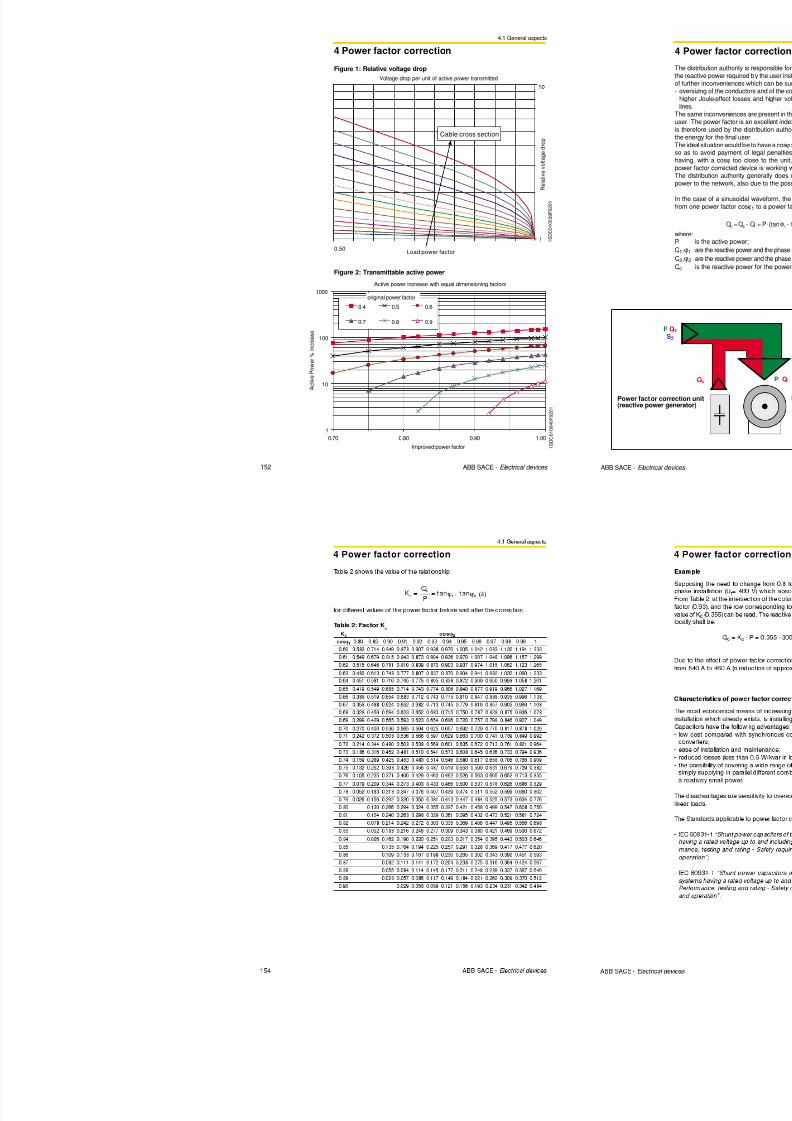
8/3/2019 ABB Electrical Install Ti On Handbook 4th Edition
http://slidepdf.com/reader/full/abb-electrical-install-ti-on-handbook-4th-edition 202/322
2.2 Installation and dimensioning of cables
2 Protection of feeders
≤ 0.3 De
≤ 0.3 De
≤ 0.3 De
≤ 0.3 De
≤ 0.3 De
30 On unperforated tray1
C
31 On perforated tray1 E or F
Methods ofinstallation
Item n. Description
Referencemethod of
installation to beused to
obtain current-carryingcapacity
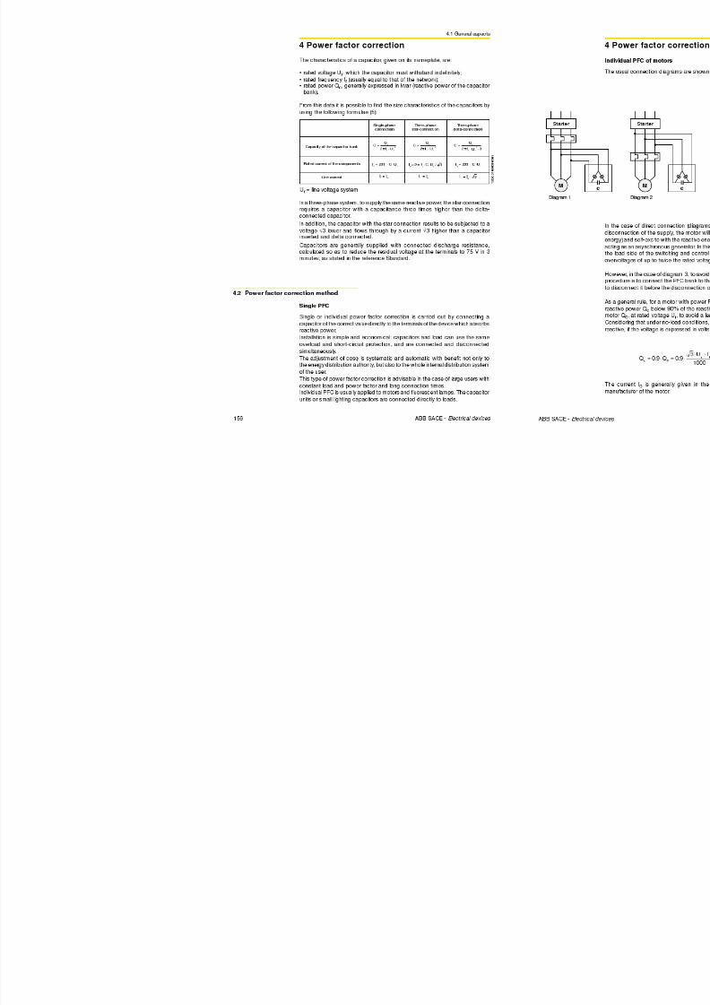
8/3/2019 ABB Electrical Install Ti On Handbook 4th Edition
http://slidepdf.com/reader/full/abb-electrical-install-ti-on-handbook-4th-edition 203/322
28 ABB SACE - Electrical devices
≤ 0.3 De
32 On brackets or on a wire mesh1 E or F
33Spaced more than 0.3 times cablediameter from a wall
E or F or G
34 On ladder E or F
35Single-core or multi-core cablesuspended from or incorporating a
support wire
E or F
36Bare or insulated conductors oninsulators
G

8/3/2019 ABB Electrical Install Ti On Handbook 4th Edition
http://slidepdf.com/reader/full/abb-electrical-install-ti-on-handbook-4th-edition 204/322
2.2 Installation and dimensioning of cables
2 Protection of feeders
> 2 De2
De1 De2
a)
Correction factor k2
The cable current carrying capacity is influenced by the presence of other cablesinstalled nearby. The heat dissipation of a single cable is different from that ofthe same cable when installed next to the other ones. The factor k2 is tabled
according to the installation of cables laid close together in layers or bunches.
Definition of layer or bunchlayer: several circuits constituted by cables installed one next to another, spaced
or not, arranged horizontally or vertically. The cables on a layer are installed ona wall, tray, ceiling, floor or on a cable ladder;
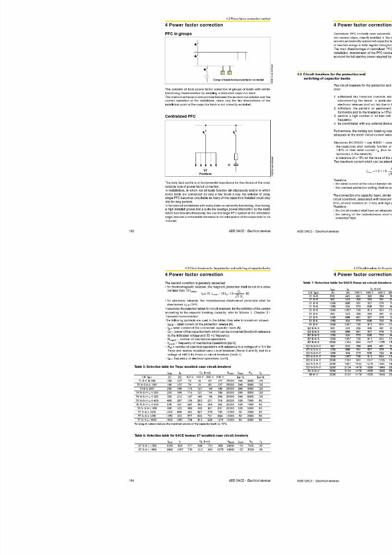
8/3/2019 ABB Electrical Install Ti On Handbook 4th Edition
http://slidepdf.com/reader/full/abb-electrical-install-ti-on-handbook-4th-edition 205/322
32 ABB SACE - Electrical devices
b)
c)
< 3 0 c m
1 S D C 0 1 0 0 0 2 F 0 0 0 1
bunch: several circuits constituted by cables that are not spaced and are notinstalled in a layer; several layers superimposed on a single support (e.g. tray)
are considered to be a bunch.
Cables in layers: a) spaced; b) not spaced; c) double layer
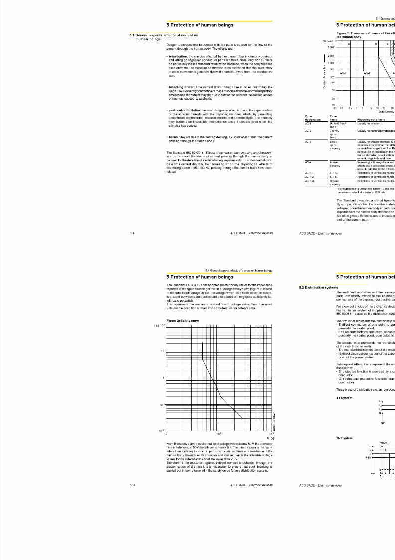
8/3/2019 ABB Electrical Install Ti On Handbook 4th Edition
http://slidepdf.com/reader/full/abb-electrical-install-ti-on-handbook-4th-edition 206/322
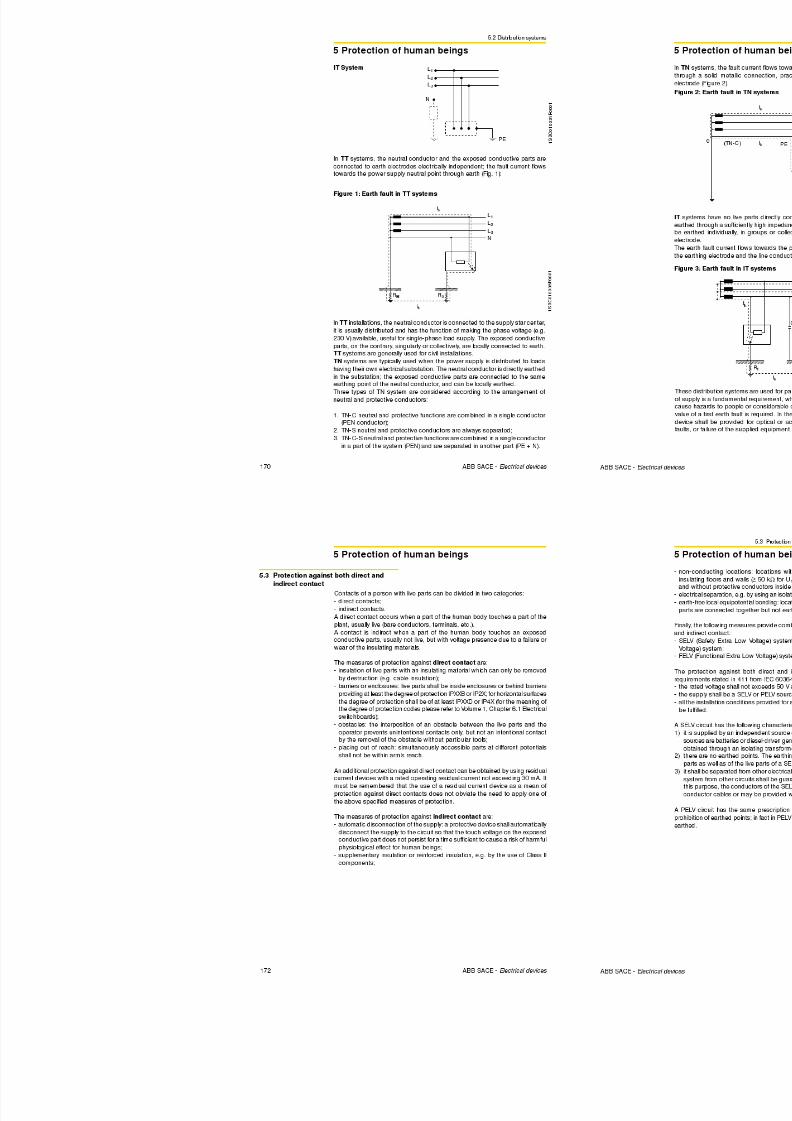
8/3/2019 ABB Electrical Install Ti On Handbook 4th Edition
http://slidepdf.com/reader/full/abb-electrical-install-ti-on-handbook-4th-edition 207/322
2.2 Installation and dimensioning of cables
2 Protection of feeders
Installationmethod
Insulation
S[mm2]
Loadedconductors
2 3 2 3 2 3 2 3 2 3 2 3 2 3 2 3 2 3
1.5 19 17 14.5 13.5 18.5 16.5 14 13.0 23 20
2.5 26 23 19.5 18 20 19 14.5 14 25 22 18.5 17.5 19.5 18 14.5 13.5 31 28
4 35 31 26 24 27 25 20 18.5 33 30 25 23 26 24 20 17.5 42 37
6 45 40 34 31 35 32 26 24 42 38 32 29 33 31 25 23 54 4810 61 54 46 42 48 44 36 32 57 51 43 39 45 41 33 31 75 66
16 81 73 61 56 64 58 48 43 76 68 57 52 60 55 44 41 100 88
25 106 95 80 73 84 76 63 57 99 89 75 68 78 71 58 53 133 117
35 131 117 99 89 103 94 77 70 121 109 92 83 96 87 71 65 164 144
50 158 141 119 108 125 113 93 84 145 130 110 99 115 104 86 78 198 175
70 200 179 151 136 158 142 118 107 183 164 139 125 145 131 108 98 253 222
A1
Al
PVC XLPEEPR PVC
Cu
XLPEEPR
A2
Cu Al
XLPEEPR PVC
XLPEEPR PVC
XLPEEPR
CuConductor
13
15
19.5
Table 8: Current carrying capacity of cables with PVC or EPR/XLPEinsulation (method A-B-C)
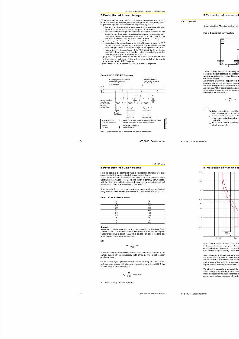
8/3/2019 ABB Electrical Install Ti On Handbook 4th Edition
http://slidepdf.com/reader/full/abb-electrical-install-ti-on-handbook-4th-edition 208/322
38 ABB SACE - Electrical devices
95 241 216 182 164 191 171 142 129 220 197 167 150 175 157 130 118 306 269
120 278 249 210 188 220 197 164 149 253 227 192 172 201 180 150 135 354 312
150 318 285 240 216 253 226 189 170 290 259 219 196 230 206 172 155
185 362 324 273 245 288 256 215 194 329 295 248 223 262 233 195 176
240 424 380 321 286 338 300 252 227 386 346 291 261 307 273 229 207
300 486 435 367 328 387 344 289 261 442 396 334 298 352 313 263 237
400
500
630
2.2 Installation and dimensioning of cables
2 Protection of feeders
Table 8: Current carrying capacity of cables with PVC or EPR/XLPEinsulation (method E-F-G)
or
Installationmethod
Insulation
XLPEEPR PVC
XLPEEPR PVC
XLPEEPR PVC
XLPEEPR PVC
XLPEEPR PVC
XLPEEPR PVC
XLPEEPR PVC
XLPEEPR PVC
S[mm2]
Loadedconductors
1.5 26 22 23 18.5
2.5 36 30 28 23 32 2 524 19.5
4 49 40 38 31 42 34 32 26
6 63 51 49 39 54 43 42 33
10 86 70 67 54 75 60 58 46
16 115 94 91 73 100 80 77 61
25 149 119 108 89 127 101 97 78 161 131 121 98 13 5110 103 84
35 185 148 135 111 158 126 120 96 200 162 150 122 169 137 129 10550 225 180 164 135 192 153 146 117 242 196 184 149 207 167 159 128
70 289 232 211 173 246 196 187 150 310 251 237 192 268 216 206 166
95 352 282 257 210 298 238 227 183 377 304 289 235 328 264 253 203
120 410 328 300 244 346 276 263 212 437 352 337 273 383 308 296 237
150 473 379 346 282 399 319 304 245 504 406 389 316 444 356 343 274
185 542 434 397 322 456 364 347 280 575 463 447 363 510 409 395 315
F
Cu Al Cu Al
E
2 3
Al Cu Al
2 3
Cu
25
84135
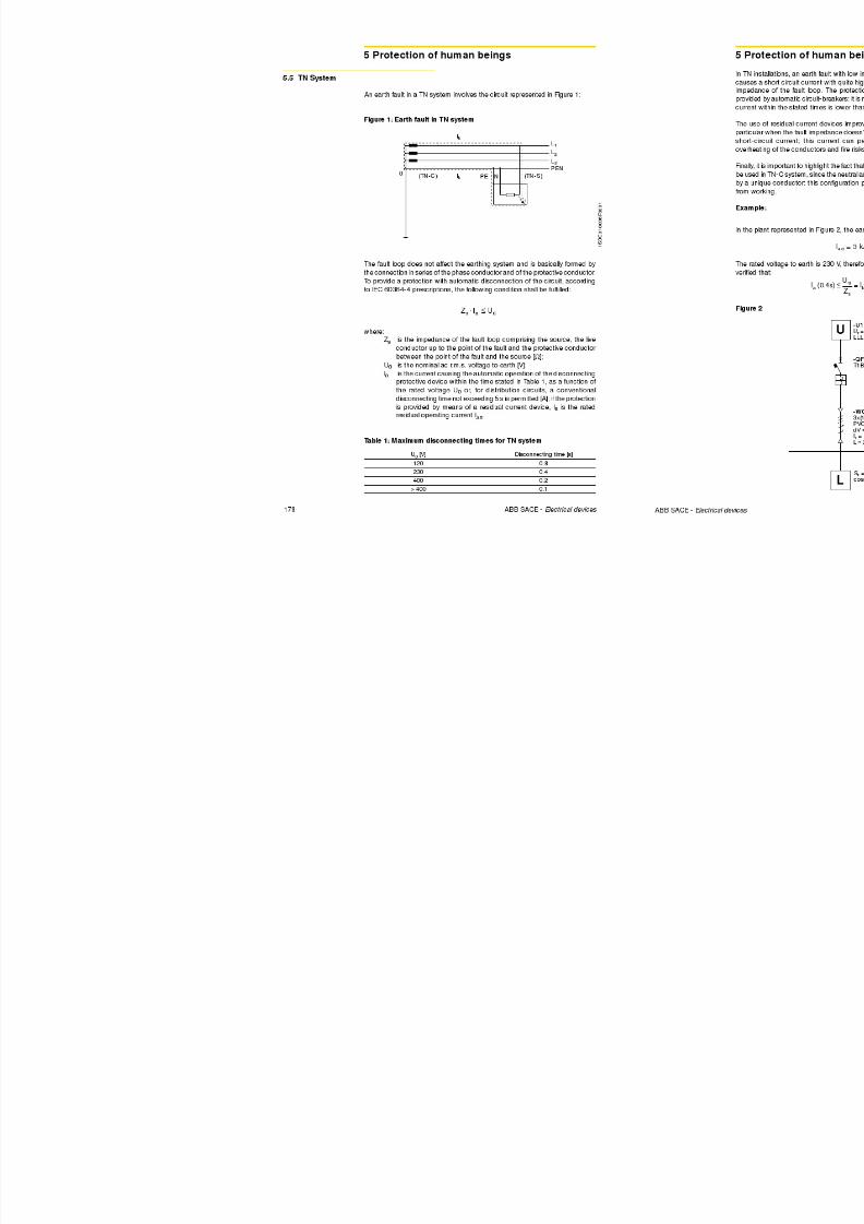
8/3/2019 ABB Electrical Install Ti On Handbook 4th Edition
http://slidepdf.com/reader/full/abb-electrical-install-ti-on-handbook-4th-edition 209/322
40 ABB SACE - Electrical devices
240 641 514 470 380 538 430 409 330 679 546 530 430 607 485 471 375
300 741 593 543 439 621 497 471 381 783 629 613 497 703 561 547 434
400 940 754 740 600 823 656 663 526
500 1083 868 856 694 946 749 770 610
630 1254 1005 996 808 1088 855 899 711
2.2 Installation and dimensioning of cables
2 Protection of feeders
Installationmethod
Loadedconductors
2 3 3 2 3 3 2 3
23 19 21 28 24 27 25 21
31 26 29 38 33 36 33 28
40 35 38 51 44 47 44 37
25 21 23 31 26 30 26 22
34 28 31 42 35 41 36 30
45 37 41 55 47 53 47 40
57 48 52 70 59 67 60 51
77 65 70 96 81 91 82 69
102 86 92 127 107 119 109 92133 112 120 166 140 154 142 120
163 137 147 203 171 187 174 147
202 169 181 251 212 230 215 182
247 207 221 307 260 280 264 223
296 249 264 369 312 334 317 267
340 286 303 424 359 383 364 308
500 V
750 V
C
120
35
50
70
95
6
10
1625
4
1.5
2.5
4
1.5
2.5
Bare cable notexposed to touch
S[mm2]
PVC covered orbare exposed to touch
PVC covered orbare exposed to touch
Metallic sheath temperature 70 °C Metallic sheath temperature 105 °CSheath
Metallic sheath temperature
or or
Table 9: Current carrying capacity of cables with mineral insulation
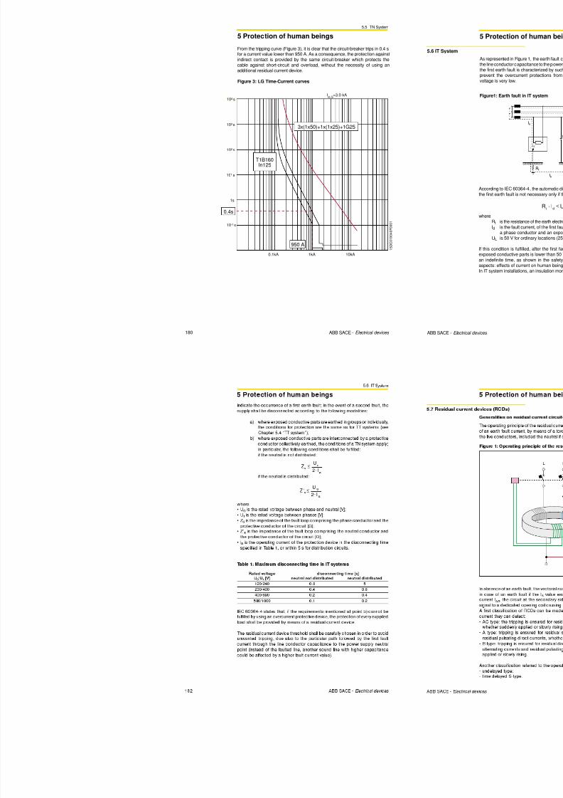
8/3/2019 ABB Electrical Install Ti On Handbook 4th Edition
http://slidepdf.com/reader/full/abb-electrical-install-ti-on-handbook-4th-edition 210/322
42 ABB SACE - Electrical devices
388 327 346 485 410 435 416 352
440 371 392 550 465 492 472 399
514 434 457 643 544 572 552 466
Note 1 For single-core cables the sheaths of the cables of the circuit are connected together at both ends.Note 2 For bare cables exposed to touch, values should be multiplied by 0.9.
Note 3 De is the external diameter of the cable.
Note 4 For metallic sheath temperature 105 °C no correction for grouping need to be applied.
150
185
240
2.2 Installation and dimensioning of cables
2 Protection of feeders
totzkIkkkII
03210==
Table 10: Correction factors for ambient ground temperatures otherthan 20 °C
Installation in ground: choice of the cross section accordingto cable carrying capacity and type of installation
The current carrying capacity of a cable buried in the ground is calculated byusing this formula:
where:• I0 is the current carrying capacity of the single conductor for installation in the
ground at 20°C reference temperature;• k1 is the correction factor if the temperature of the ground is other than 20°C;• k2 is the correction factor for adjacent cables;• k3 is the correction factor if the soil thermal resistivity is different from the
reference value, 2.5 Km/W.
Correction factor k1
The current carrying capacity of buried cables refers to a ground temperature
of 20 °C. If the ground temperature is different, use the correction factor k1
shown in Table 10 according to the insulation material.
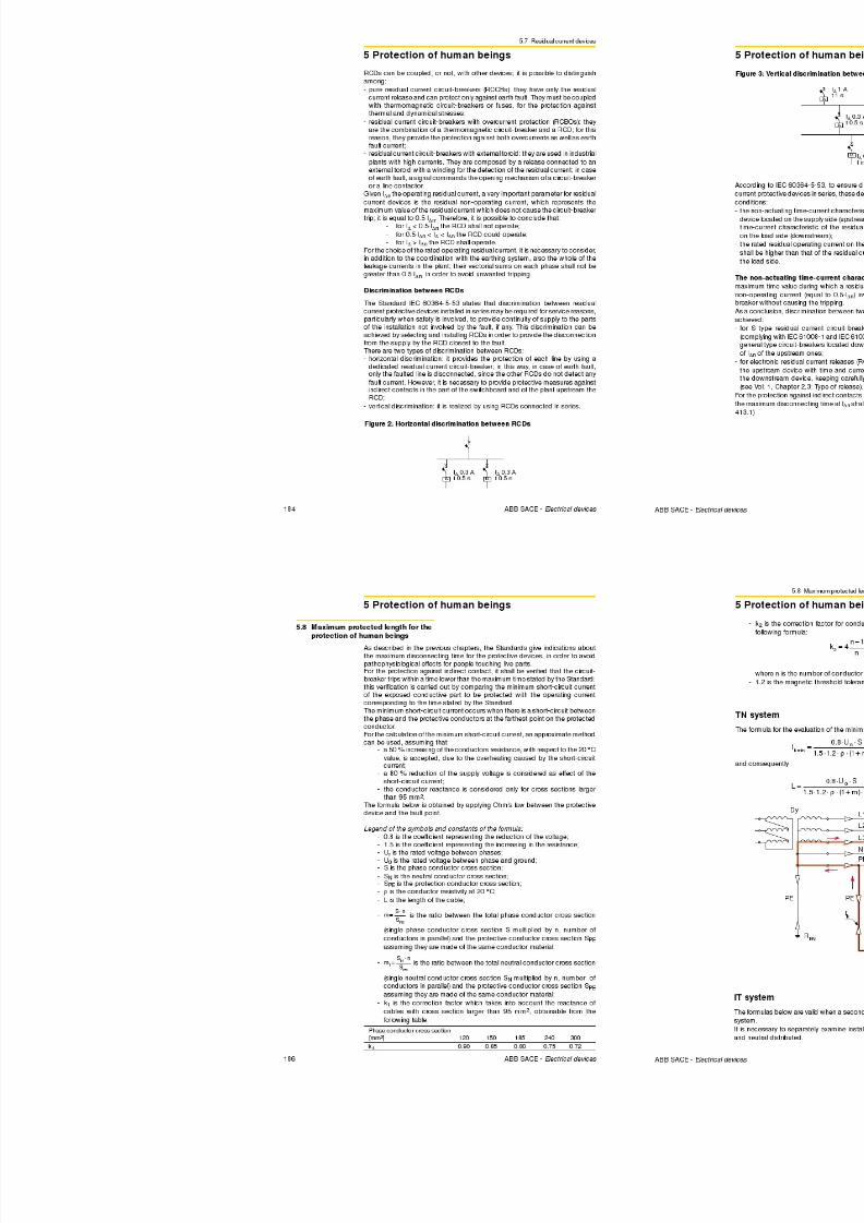
8/3/2019 ABB Electrical Install Ti On Handbook 4th Edition
http://slidepdf.com/reader/full/abb-electrical-install-ti-on-handbook-4th-edition 211/322
44 ABB SACE - Electrical devices
than 20 C
Groundtemperature
°C
10
1525
30
35
40
45
50
55
60
65
70
7580
PVC
1.10
1.050.95
0.89
0.84
0.77
0.71
0.63
0.55
0.45
–
–
– –
XLPE and EPR
1.07
1.040.96
0.93
0.89
0.85
0.80
0.76
0.71
0.65
0.60
0.53
0.460.38
Insulation
2.2 Installation and dimensioning of cables
2 Protection of feeders
a
Table 12: Reduction factors for multi-core cables laid in single wayducts in the ground
Numberof circuits
2
3
4
56
Nil (cablestouching)
0.85
0.75
0.70
0.650.60
0.25 m
0.90
0.85
0.80
0.800.80
0.5 m
0.95
0.90
0.85
0.850.80
1.0 m
0.95
0.95
0.90
0.900.90
Cable to cable clearance (a)
NOTE The given values apply to an installation depth of 0.7 m and a soil thermal resistivity of 2.5 Km/W.
Multi-core cables
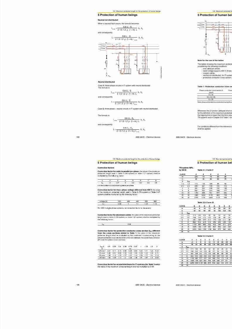
8/3/2019 ABB Electrical Install Ti On Handbook 4th Edition
http://slidepdf.com/reader/full/abb-electrical-install-ti-on-handbook-4th-edition 212/322
46 ABB SACE - Electrical devices
a a
Number of single-core
circuits oftwo or three cables
2
3
4
5
6
Nil (ductstouching)
0.80
0.70
0.65
0.60
0.60
0.25 m
0.90
0.80
0.75
0.70
0.70
0.5 m
0.90
0.85
0.80
0.80
0.80
1.0 m
0.95
0.90
0.90
0.90
0.90
Duct to duct clearance (a)
NOTE The given values apply to an installation depth of 0.7 m and a soil thermal resistivity of 2.5 Km/W.
Single-core cables
Table 13: Reduction factors for single-core cables laid in single way
ducts in the ground
2.2 Installation and dimensioning of cables
2 Protection of feeders
tot
bb
bk
I
kkk
II ==
321
'
To summarize:
Use this procedure to determine the cross section of the cable:1. from Table 10, determine the correction factor k1 according to the insulation
material and the ground temperature;
2. use Table 11, Table 12, Table 13 or the formula for groups of non-similarcables to determine the correction factor k2 according to the distancebetween cables or ducts;
3. from Table 14 determine factor k3 corresponding to the soil thermal resistivity;
4. calculate the value of the current I’b by dividing the load current Ib (or therated current of the protective device) by the product of the correction factorscalculated:
5. from Table 15, determine the cross section of the cable with I0 ≥ I’b, accordingto the method of installation, the insulation and conductive material and the
number of live conductors;
6. the actual cable current carrying capacity is calculated by.
Table 15: Current carrying capacity of cables buried in the ground
zkkII
210= k
3
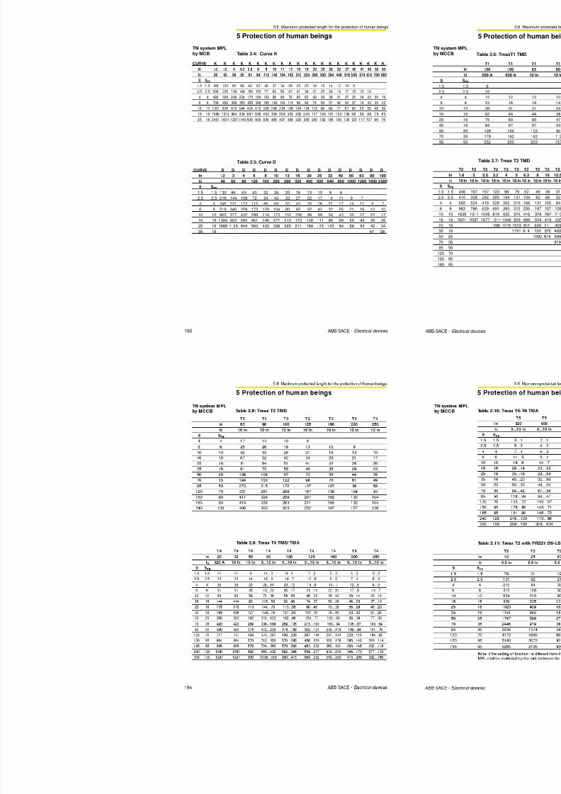
8/3/2019 ABB Electrical Install Ti On Handbook 4th Edition
http://slidepdf.com/reader/full/abb-electrical-install-ti-on-handbook-4th-edition 213/322
48 ABB SACE - Electrical devices
1 S D C 0 1 0 0 0 8 F 0 2 0 1
Installationmethod
Insulation
S[mm2]
Loadedconductors
2 3 2 3 2 3 2 3
1.5 26 22 22 18
2.5 34 29 29 24 26 22 22 18.5
4 44 37 38 31 34 29 29 24
6 56 46 47 39 42 36 36 30
10 73 61 63 52 56 47 48 40
16 95 79 81 67 73 61 62 52
25 121 101 104 86 93 78 80 66
35 146 122 125 103 112 94 96 8050 173 144 148 122 132 112 113 94
70 213 178 183 151 163 138 140 117
95 252 211 216 179 193 164 166 138
120 287 240 246 203 220 186 189 157
150 324 271 278 230 249 210 213 178
185 363 304 312 258 279 236 240 200
240 419 351 361 297 322 272 277 230
300 474 396 408 336 364 308 313 260
XLPEEPR PVC
XLPEEPR PVC
D
Cu AlConductor
Table 15: Current carrying capacity of cables buried in the ground
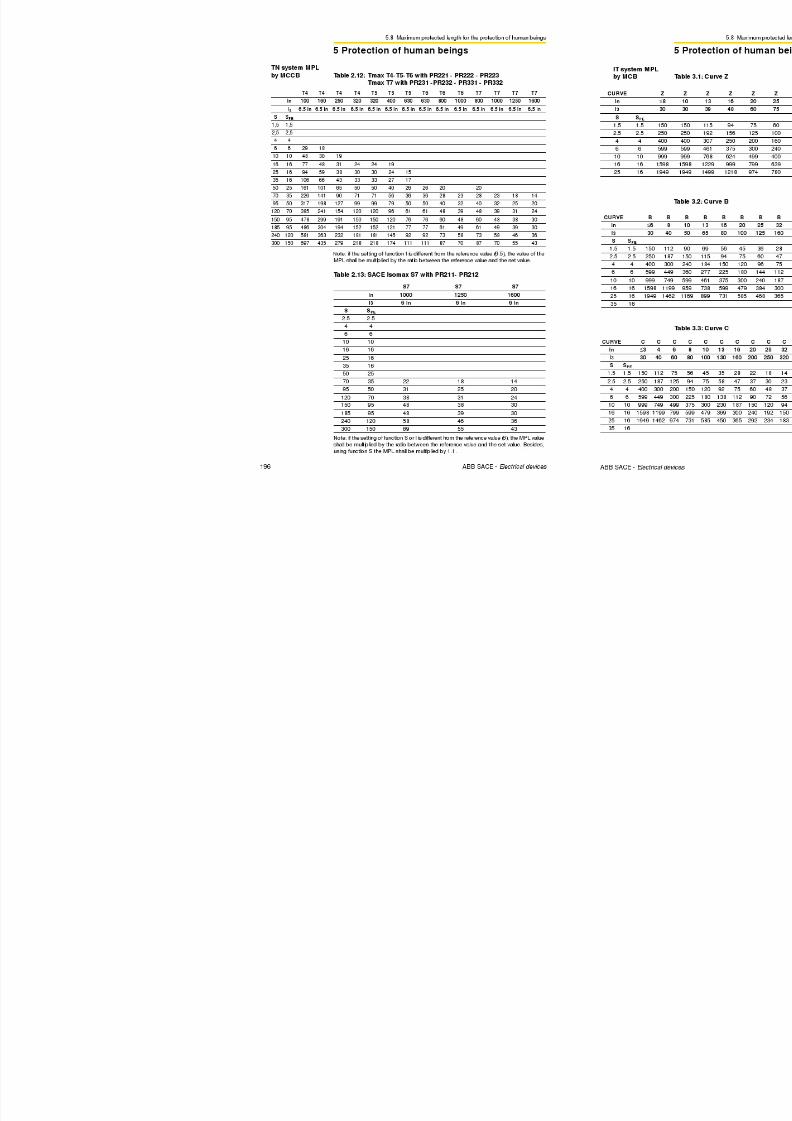
8/3/2019 ABB Electrical Install Ti On Handbook 4th Edition
http://slidepdf.com/reader/full/abb-electrical-install-ti-on-handbook-4th-edition 214/322
2.2 Installation and dimensioning of cables
2 Protection of feeders
Example of cable dimensioning in a balanced three-phase circuit without harmonics
Dimensioning of a cable with the following characteristics: • conductor material: : copper
• insulation material: : PVC
• type of cable: : multi-core
• installation: : cables bunched on horizontalperforated tray
• load current: : 100 A
Installation conditions: • ambient temperature: : 40 °C
• adjacent circuits with a) three-phase circuit consisting of 4
single-core cables, 4x50 mm2;
b) three-phase circuit consisting of onemulti-core cable, 1x(3x50) mm2;
c) three-phase circuit consisting of 9single-core (3 per phase) cables,
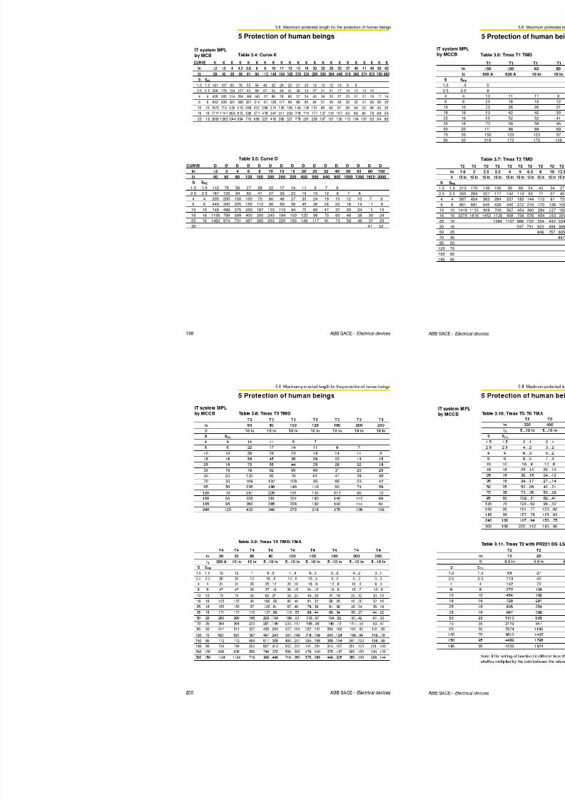
8/3/2019 ABB Electrical Install Ti On Handbook 4th Edition
http://slidepdf.com/reader/full/abb-electrical-install-ti-on-handbook-4th-edition 215/322
52 ABB SACE - Electrical devices
a
d
bc
1 S D C 0 1 0 0 0 8 F 0 0 0 1
g ( p p ) ,
9x95 mm2;
d) single-phase circuit consisting of 2single-core cables, 2x70 mm2.
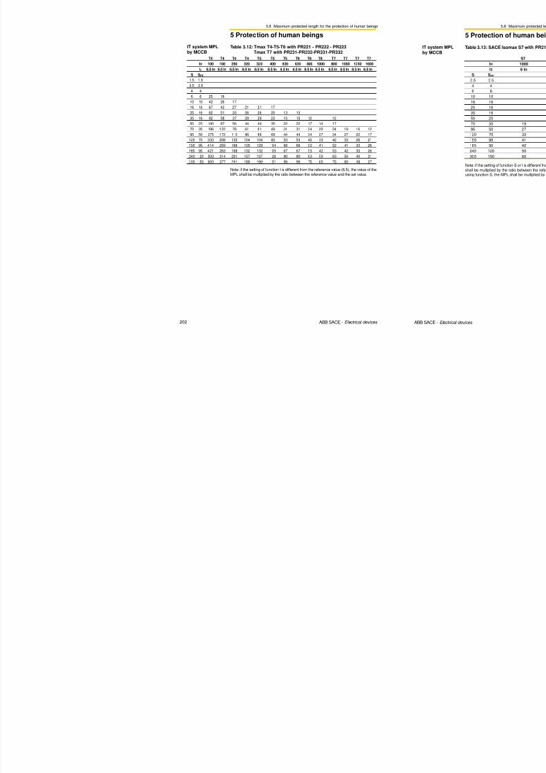
8/3/2019 ABB Electrical Install Ti On Handbook 4th Edition
http://slidepdf.com/reader/full/abb-electrical-install-ti-on-handbook-4th-edition 216/322

8/3/2019 ABB Electrical Install Ti On Handbook 4th Edition
http://slidepdf.com/reader/full/abb-electrical-install-ti-on-handbook-4th-edition 217/322
2.2 Installation and dimensioning of cables
2 Protection of feeders
Table 1: Resistance and reactance per unit of length of copper cables
single-core cable two-core/three-core cable
S r[Ω/km] x[Ω/km] r[Ω/km] x[Ω/km][mm2] @ 80 [°C] @ 80 [°C]
1.5 14.8 0.168 15.1 0.118
2.5 8.91 0.156 9.08 0.109
4 5.57 0.143 5.68 0.101
6 3.71 0.135 3.78 0.0955
10 2.24 0.119 2.27 0.0861
16 1.41 0.112 1.43 0.0817
25 0.889 0.106 0.907 0.0813
35 0.641 0.101 0.654 0.0783
50 0.473 0.101 0.483 0.0779
70 0.328 0.0965 0.334 0.0751
95 0.236 0.0975 0.241 0.0762
120 0.188 0.0939 0.191 0.074
150 0.153 0.0928 0.157 0.0745
185 0.123 0.0908 0.125 0.0742
240 0.0943 0.0902 0.0966 0.0752
300 0.0761 0.0895 0.078 0.075
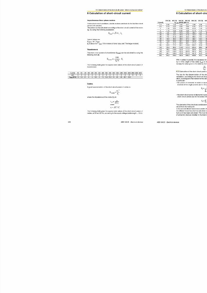
8/3/2019 ABB Electrical Install Ti On Handbook 4th Edition
http://slidepdf.com/reader/full/abb-electrical-install-ti-on-handbook-4th-edition 218/322
58 ABB SACE - Electrical devices
Table 2: Resistance and reactance per unit of length of aluminium
cables
single-core cable two-core/three-core cable
S r[Ω/km] x[Ω/km] r[Ω/km] x[Ω/km][mm2] @ 80 [°C] @ 80 [°C]
1.5 24.384 0.168 24.878 0.118
2.5 14.680 0.156 14.960 0.109
4 9.177 0.143 9.358 0.101
6 6.112 0.135 6.228 0.0955
10 3.691 0.119 3.740 0.0861
16 2.323 0.112 2.356 0.0817
25 1.465 0.106 1.494 0.0813
35 1.056 0.101 1.077 0.0783
50 0.779 0.101 0.796 0.0779
70 0.540 0.0965 0.550 0.0751
95 0.389 0.0975 0.397 0.0762
120 0,310 0.0939 0.315 0.074
150 0.252 0.0928 0.259 0.0745
185 0.203 0.0908 0.206 0.0742
240 0.155 0.0902 0.159 0.0752
300 0.125 0.0895 0.129 0.075
2.2 Installation and dimensioning of cables
2 Protection of feeders
Table 5: Specific voltage drop at cosϕ = 0.85 for copper cables
cosϕ = 0.85single- core cable two- core cable three-core cable
S[mm2] single-phase three- phase single-phase three- phase
1.5 25.34 21.94 25.79 22.34
2.5 15.31 13.26 15.55 13.47
4 9.62 8.33 9.76 8.45
6 6.45 5.59 6.53 5.65
10 3.93 3.41 3.95 3.4216 2.51 2.18 2.52 2.18
25 1.62 1.41 1.63 1.41
35 1.20 1.04 1.19 1.03
50 0.91 0.79 0.90 0.78
70 0.66 0.57 0.65 0.56
95 0.50 0.44 0.49 0.42
120 0.42 0.36 0.40 0.35
150 0.36 0.31 0.35 0.30
185 0.30 0.26 0.29 0.25
240 0.26 0.22 0.24 0.21
300 0.22 0.19 0.21 0.18
Table 6: Specific voltage drop at cosϕ = 0.8 for copper cables
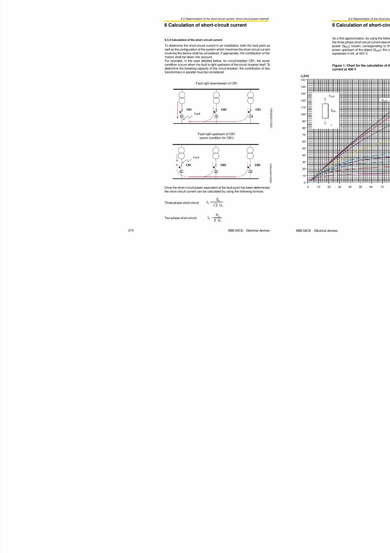
8/3/2019 ABB Electrical Install Ti On Handbook 4th Edition
http://slidepdf.com/reader/full/abb-electrical-install-ti-on-handbook-4th-edition 219/322
60 ABB SACE - Electrical devices
cosϕ = 0.8single- core cable two- core cable three-core cable
S[mm2] single-phase three- phase single-phase three- phase
1.5 23.88 20.68 24.30 21.05
2.5 14.44 12.51 14.66 12.694 9.08 7.87 9.21 7.98
6 6.10 5.28 6.16 5.34
10 3.73 3.23 3.74 3.23
16 2.39 2.07 2.39 2.07
25 1.55 1.34 1.55 1.34
35 1.15 0.99 1.14 0.99
50 0.88 0.76 0.87 0.75
70 0.64 0.55 0.62 0.54
95 0.49 0.43 0.48 0.41
120 0.41 0.36 0.39 0.34
150 0.36 0.31 0.34 0.29185 0.31 0.26 0.29 0.25
240 0.26 0.22 0.24 0.21
300 0.23 0.20 0.21 0.19
2.2 Installation and dimensioning of cables
2 Protection of feeders
Table 9: Specific voltage drop at cosϕ = 0.9 for aluminium cables
cosϕ = 0.9single-core cable two-core cable three-core cable
S[mm2] single-phase three- phase single-phase three- phase
1.5 44.04 38.14 44.88 38.87
2.5 26.56 23.00 27.02 23.40
4 16.64 14.41 16.93 14.66
6 11.12 9.63 11.29 9.78
10 6.75 5.84 6.81 5.8916 4.28 3.71 4.31 3.73
25 2.73 2.36 2.76 2.39
35 1.99 1.72 2.01 1.74
50 1.49 1.29 1.50 1.30
70 1.06 0.92 1.06 0.91
95 0.78 0.68 0.78 0.68
120 0.64 0.55 0.63 0.55
150 0.53 0.46 0.53 0.46
185 0.44 0.38 0.44 0.38
240 0.36 0.31 0.35 0.30
300 0.30 0.26 0.30 0.26
Table 10: Specific voltage drop at cosϕ = 0.85 for aluminium cables
cosϕ = 0.85
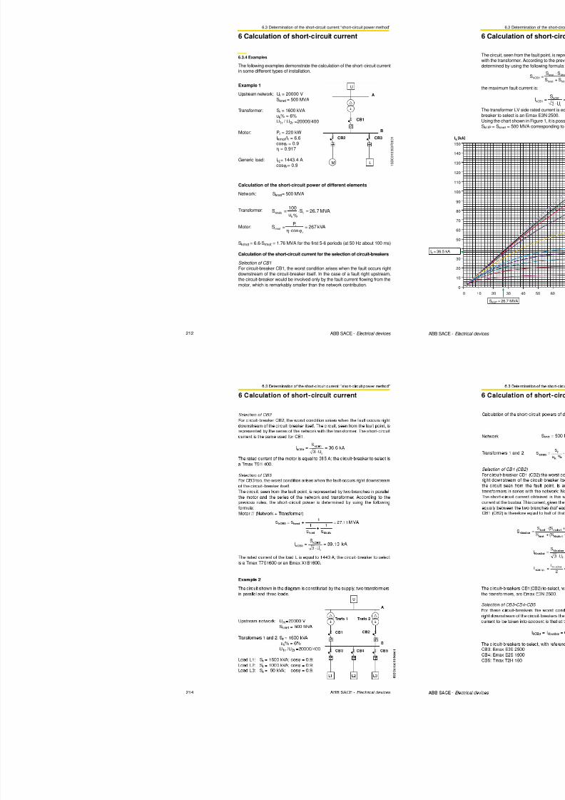
8/3/2019 ABB Electrical Install Ti On Handbook 4th Edition
http://slidepdf.com/reader/full/abb-electrical-install-ti-on-handbook-4th-edition 220/322
62 ABB SACE - Electrical devices
ϕ
single- core cable two- core cable three-core cable
S[mm2] single-phase three- phase single-phase three- phase
1.5 41.63 36.05 42.42 36.73
2.5 25.12 21.75 25.55 22.12
4 15.75 13.64 16.02 13.876 10.53 9.12 10.69 9.26
10 6.40 5.54 6.45 5.58
16 4.07 3.52 4.09 3.54
25 2.60 2.25 2.63 2.27
35 1.90 1.65 1.91 1.66
50 1.43 1.24 1.43 1.24
70 1.02 0.88 1.01 0.88
95 0.76 0.66 0.76 0.65
120 0.63 0.54 0.61 0.53
150 0.53 0.46 0.52 0.45
185 0.44 0.38 0,43 0.37
240 0.36 0.31 0.35 0.30
300 0.31 0.27 0.30 0.26
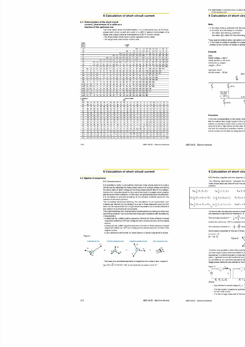
8/3/2019 ABB Electrical Install Ti On Handbook 4th Edition
http://slidepdf.com/reader/full/abb-electrical-install-ti-on-handbook-4th-edition 221/322
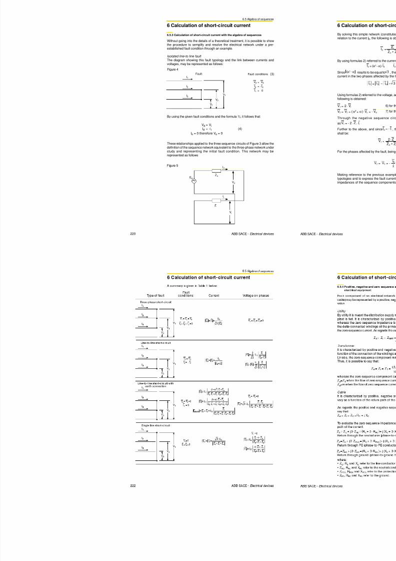
8/3/2019 ABB Electrical Install Ti On Handbook 4th Edition
http://slidepdf.com/reader/full/abb-electrical-install-ti-on-handbook-4th-edition 222/322
2.3 Protection against overload
2 Protection of feeders
Ib ≤ In ≤ 0.9.Iz
Ib
1 S D C 0 1 0 0 1 0 F 0 0 0 1
In
Iz
Ib
1 S
D C 0 1 0 0 1 1 F 0 0 0 1
In
Iz0.9
To summarize:to carry out by a fuse protection against overload, the followingmust be achieved:
and this means that the cable is not fully exploited.
Circuit-breaker: choice of rated current
Fuse: choice of rated current
Where the use of a single conductor per phase is not feasible, and the currentsin the parallel conductors are unequal, the design current and requirements foroverload protection for each conductor shall be considered individually.
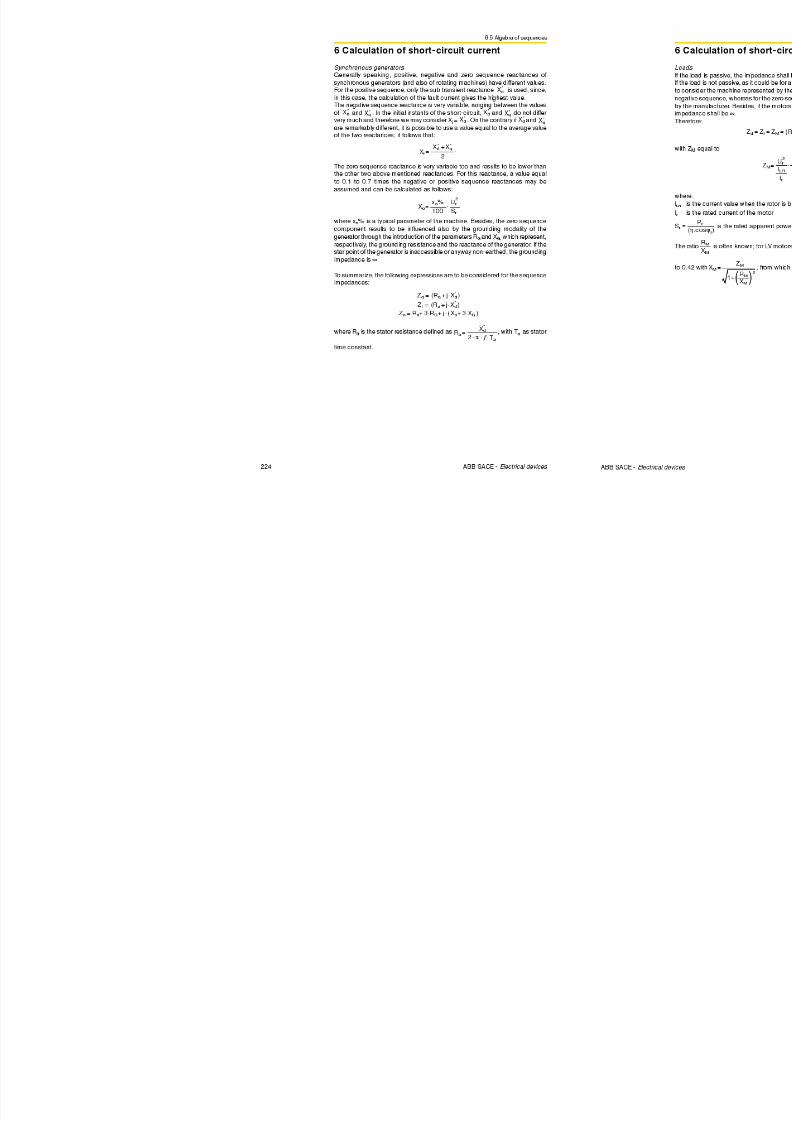
8/3/2019 ABB Electrical Install Ti On Handbook 4th Edition
http://slidepdf.com/reader/full/abb-electrical-install-ti-on-handbook-4th-edition 223/322
68 ABB SACE - Electrical devices
Examples
Example 1
Load specifications
Pr = 70 kW; Ur = 400 V; cosϕ = 0.9; three-phase load so Ib = 112 A
Cable specifications
Iz = 134 A
Protective device specifications
T1B160 TMD In125; set current I1 = 125 A

8/3/2019 ABB Electrical Install Ti On Handbook 4th Edition
http://slidepdf.com/reader/full/abb-electrical-install-ti-on-handbook-4th-edition 224/322
2.4 Protection against short-circuit
2 Protection of feeders
S D C 0 1 0 0 1 1 F 0 0 0 1
[(KA)2s] 102
10-1
10-2
10
1
10-3
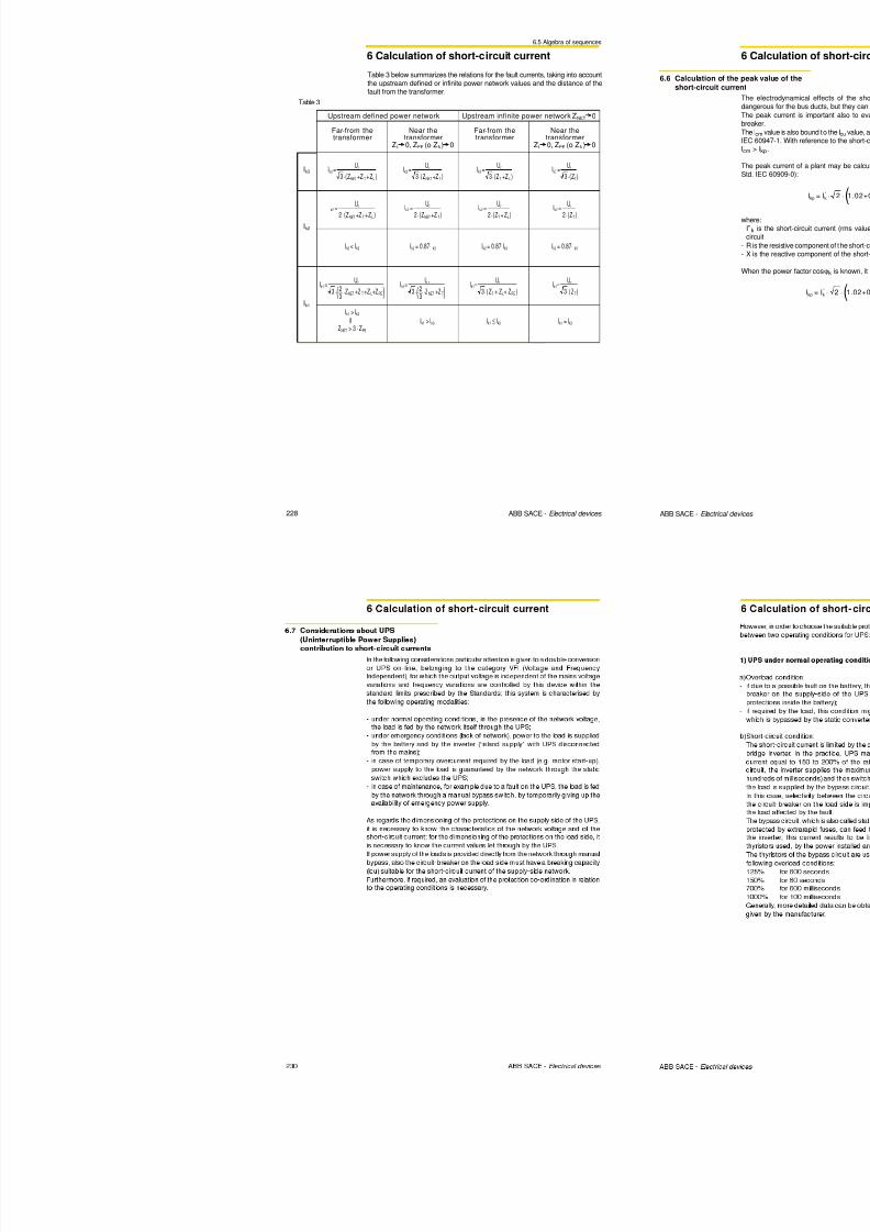
8/3/2019 ABB Electrical Install Ti On Handbook 4th Edition
http://slidepdf.com/reader/full/abb-electrical-install-ti-on-handbook-4th-edition 225/322
72 ABB SACE - Electrical devices
1 S
10-1 1 10 [KA]
This verification can be simplified by comparing only the let-through energyvalue of the circuit-breaker at the maximum short-circuit current with thewithstood energy of the cable and by ensuring that the circuit breaker trips
instantaneously at the minimum short-circuit current: the threshold of the short-circuit protection (taking into consideration also the tolerances) shall thereforebe lower than the minimum short-circuit current at the end of the conductor.
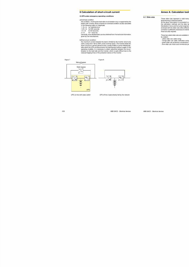
8/3/2019 ABB Electrical Install Ti On Handbook 4th Edition
http://slidepdf.com/reader/full/abb-electrical-install-ti-on-handbook-4th-edition 226/322
2.4 Protection against short-circuit
2 Protection of feeders
N
d
S
Sk+
.=1
1
3
2
if S = S k is 0 58;
Correction factor for voltage other than 400 V: k v
Multiply the length value obtained from the table by the correction factor kv:
Ur [V] kv(three-phase value)
230(*) 0.58400 1
440 1.1500 1.25690 1.73
(*) 230 V single-phase is the equivalent of a three-phase 400 V system with distributedneutral and with the cross section of the phase conductor the same as the cross section
area of the neutral conductor, so that kvis 0.58.
Correction factor for distributed neutral: k d
Multiply the length value obtained from the table by the correction factor kd:
where
• S is the phase cross section [mm2];• S N is the neutral cross section [mm2].
In particular:
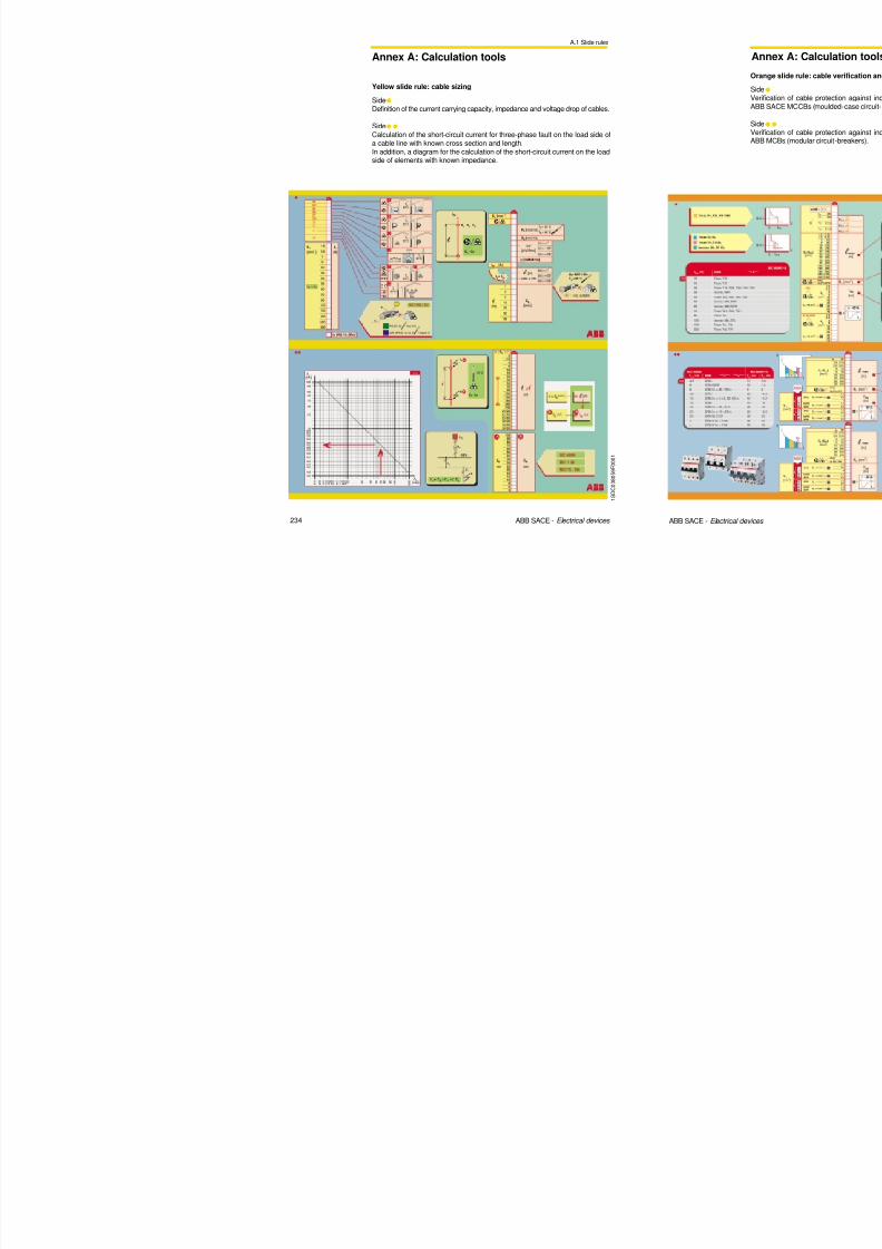
8/3/2019 ABB Electrical Install Ti On Handbook 4th Edition
http://slidepdf.com/reader/full/abb-electrical-install-ti-on-handbook-4th-edition 227/322
76 ABB SACE - Electrical devices
if S = SN kd is 0.58;
if S = 2 SN kd is 0.39..
Correction factor for aluminium conductors: k r
If the cable is in aluminium, multiply the length value obtained from the tableabove by the correction factor kr = 0.67.
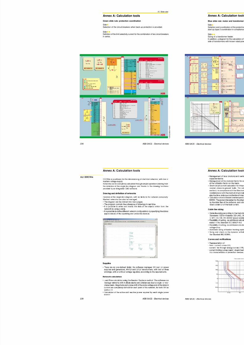
8/3/2019 ABB Electrical Install Ti On Handbook 4th Edition
http://slidepdf.com/reader/full/abb-electrical-install-ti-on-handbook-4th-edition 228/322
2.5 Neutral and protective conductors
2 Protection of feeders
L1
L2
L3PEN
PE
L1
L2
L3
1 S D C 0 1
0 0 1 4 F 0 0 0 1
NOTE – A three-phasealternative power supplywith a non-suitable 3-poleswitch, due tounintentional circular stray
currents generatingelectromagnetic fields.
Figure 3: Three-phase alternative power supply with non-suitable3-pole switch

8/3/2019 ABB Electrical Install Ti On Handbook 4th Edition
http://slidepdf.com/reader/full/abb-electrical-install-ti-on-handbook-4th-edition 229/322
80 ABB SACE - Electrical devices
IT system: The Standard advises against distributing the neutral conductor in IT systems.If the neutral conductor is distributed, the overcurrents must be detected on
the neutral conductor of each circuit in order to disconnect all the live conductorson the corresponding circuit, including the neutral one (neutral conductorprotected and disconnected).Overcurrents do not need to be detected on the neutral conductor in any of thefollowing cases:• the neutral conductor is protected against short-circuit by a protective device
fitted upstream;• the circuit is protected by a residual current device with rated residual current
lower than 0.15 times the current carrying capacity of the corresponding neutralconductor. This device must disconnect all the live conductors, the neutral
conductor included.
For all distribution systems, whenever necessary, connection and disconnectionof the neutral conductor, shall ensure that:• the neutral conductor is not disconnected before the phase conductor;• the neutral conductor is connected at the same moment or before the phase
conductor.
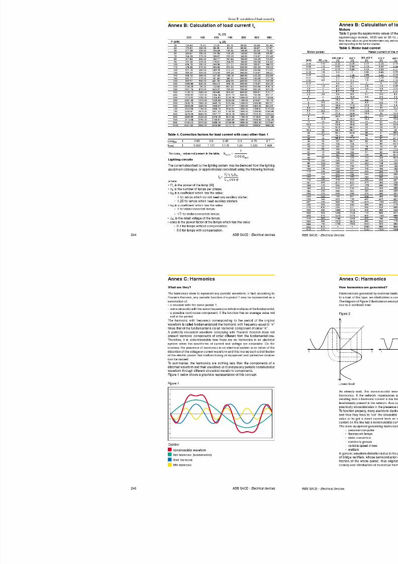
8/3/2019 ABB Electrical Install Ti On Handbook 4th Edition
http://slidepdf.com/reader/full/abb-electrical-install-ti-on-handbook-4th-edition 230/322
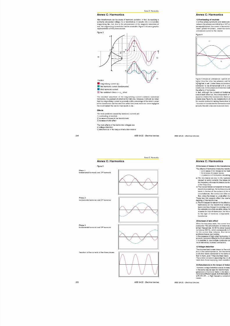
8/3/2019 ABB Electrical Install Ti On Handbook 4th Edition
http://slidepdf.com/reader/full/abb-electrical-install-ti-on-handbook-4th-edition 231/322
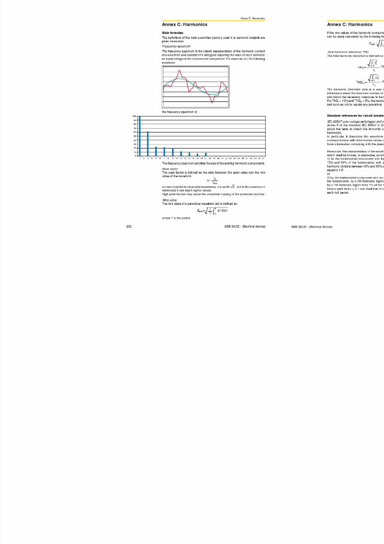
8/3/2019 ABB Electrical Install Ti On Handbook 4th Edition
http://slidepdf.com/reader/full/abb-electrical-install-ti-on-handbook-4th-edition 232/322
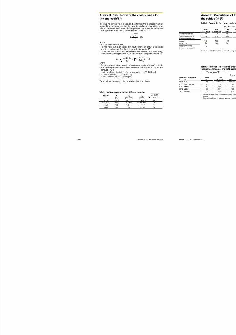
8/3/2019 ABB Electrical Install Ti On Handbook 4th Edition
http://slidepdf.com/reader/full/abb-electrical-install-ti-on-handbook-4th-edition 233/322
2.6 Busbar trunking systems
2 Protection of feeders
160 160A 4 cond. Al 4 160 0.591 0.260 1000
160 160A 5 cond. Al 5 160 0.591 0.260 1000
160 160A 4 cond. Al 4 160 0.431 0.260 500
160 160A 5 cond. Al 5 160 0.431 0.260 500
250 250A 4 cond. Al 4 250 0.394 0.202 1000
250 250A 5 cond. Al 5 250 0.394 0.202 1000250 250A 4 cond. Al 4 250 0.226 0.202 500
250 250A 5 cond. Al 5 250 0.226 0.202 500
315 315A 4 cond. Al 4 315 0.236 0.186 1000
315 315A 5 cond. Al 5 315 0.236 0.186 1000
315 315A 4 cond. Al 4 315 0.181 0.186 500
315 315A 5 cond. Al 5 315 0.181 0.186 500
400 400A 4 cond. Al 4 400 0.144 0.130 1000
400 400A 5 cond. Al 5 400 0.144 0.130 1000
400 400A 4 cond. Al 4 400 0.125 0.130 500
400 400A 5 cond. Al 5 400 0.125 0.130 500
500 500A 4 cond. Al 4 500 0.102 0.127 500
500 500A 5 cond. Al 5 500 0.102 0.127 500
630 630A 4 cond. Al 4 630 0.072 0.097 1000
630 630A 5 cond. Al 5 630 0.072 0.097 1000
630 630A 4 cond. Al 4 630 0.072 0.029 1000
630 630A 4 cond. Al 4 630 0.073 0.097 500
630 630A 5 cond. Al 5 630 0.073 0.097 500
800 800A 4 cond. Al 4 800 0.062 0.096 1000
Table 3: Current carrying capacity IZ0
of aluminium BTS
Number of IZ0 rph* xph Ur
Size Generic type conductors [A] [mΩ/m] [mΩ/m] [V]
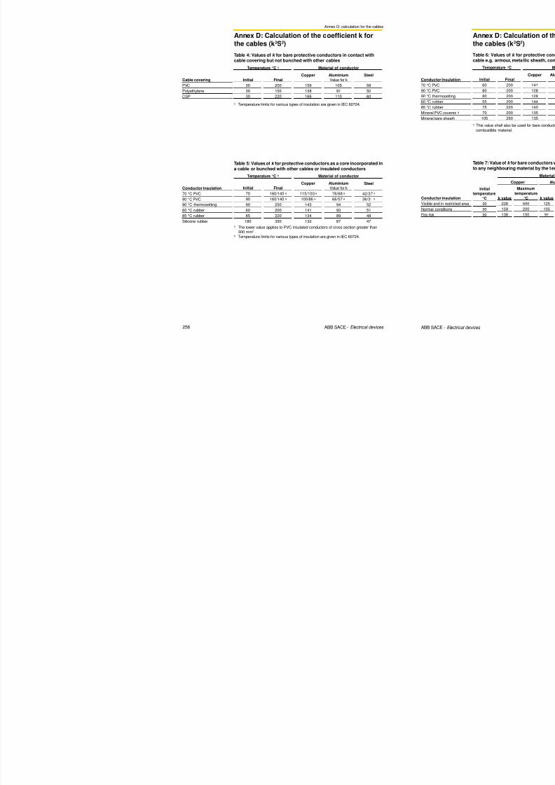
8/3/2019 ABB Electrical Install Ti On Handbook 4th Edition
http://slidepdf.com/reader/full/abb-electrical-install-ti-on-handbook-4th-edition 234/322
90 ABB SACE - Electrical devices
2.6 Busbar trunking systems
2 Protection of feeders
Ib ≤ In ≤ Iz (3)
BTS protection
Protection against overload
BTSs are protected against overload by using the same criterion as that usedfor the cables. The following formula shall be verified:
where:
• Ib is the current for which the circuit is designed;• In is the rated current of the protective device; for adjustable protective devices,
the rated current In is the set current;• Iz is the continuous current carrying capacity of the BTS.
Protection against short-circuit
The BTS must be protected against thermal overload and electrodynamic effectsdue to the short-circuit current.
Protection against thermal overload The following formula shall be fulfilled:
where:
• I2tCB is the specific let-through energy of the circuit-breaker at the maximumshort-circuit current value at the installation point. This can be extrapolatedfrom the curves shown in Volume 1 Chapter 3.4;I2t i th ith t d f th BTS d it i ll i b th
NOTE - The protectionagainst short-circuit does
not need to be checked ifMCBs up to 63 A are usedwhenever correctly
dimensioned for overloadprotection. In such cases,in fact, protection against
both thermal andelectrodynamic effects iscertainly adequatebecause of the energy andpeak limitations offered bythese protective devices.
I2t CB ≤ I2t BTS (4)
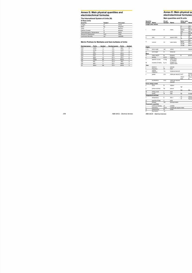
8/3/2019 ABB Electrical Install Ti On Handbook 4th Edition
http://slidepdf.com/reader/full/abb-electrical-install-ti-on-handbook-4th-edition 235/322
92 ABB SACE - Electrical devices
• I2tBTS is the withstood energy of the BTS and it is normally given by themanufacturer (see Tables 4 and 5).
Protection against electrodynamic effects The following formula shall be fulfilled:
where:• Ikp CB is the peak limited by the circuit-breaker at the maximum short-circuit
current value at the installation point. This can be extrapolated from the
limitation curves shown in Volume 1, Chapter 3.3;• Ikp BTS is the maximum peak current value of the BTS (see Tables 4 and 5).
Ikp CB ≤ Ikp BTS (5)
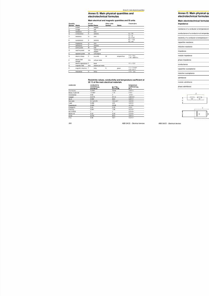
8/3/2019 ABB Electrical Install Ti On Handbook 4th Edition
http://slidepdf.com/reader/full/abb-electrical-install-ti-on-handbook-4th-edition 236/322
2.6 Busbar trunking systems
2 Protection of feeders
160 160A 4 cond. Al 112.5 67.5 67.5 30 18
160 160A 5 cond. Al 112.5 112.5 112.5 30 18
160 160A 4 cond. Al 100 60 60 17 10.2
160 160A 5 cond. Al 100 100 100 17 10.2
160 160A 4 cond. Al 100 100 100 17 10.2
250 250A 4 cond. Al 312.5 187.5 187.5 52.5 31.5250 250A 5 cond. Al 312.5 312.5 312.5 52.5 31.5
250 250A 4 cond. Al 169 101.4 101.4 26 15.6
250 250A 5 cond. Al 169 169 169 26 15.6
250 250A 4 cond. Al 169 169 169 26 15.6
315 315A 4 cond. Al 625 375 375 52.5 31.5
315 315A 5 cond. Al 625 625 625 52.5 31.5
315 315A 4 cond. Al 169 101.4 101.4 26 15.6
315 315A 5 cond. Al 169 169 169 26 15.6
315 315A 4 cond. Al 169 169 169 26 15.6
400 400A 4 cond. Al 900 540 540 63 37.8
400 400A 5 cond. Al 900 900 900 63 37.8
400 400A 4 cond. Al 625 375 375 52.5 31.5
400 400A 5 cond. Al 625 625 625 52.5 31.5
400 400A 4 cond. Al 625 625 625 52.5 31.5
500 500A 4 cond. Al 625 375 375 52.5 31.5
500 500A 5 cond. Al 625 625 625 52.5 31.5
500 500A 4 cond. Al 625 625 625 52.5 31.5
630 630A 4 cond. Al 1296 777.6 777.6 75.6 45.4
630 630A 5 cond. Al 1296 1296 1296 75.6 45.4
630 630A 4 cond. Al 1444 1444 866.4 80 48
I2tph I2tN I2tPE Ipeakph IpeakN
Size Generic type [(kA)2s] [(kA)2s] [(kA)2s] [kA] [kA]
Table 5: Values of the withstood energy and peak current ofaluminium BTS
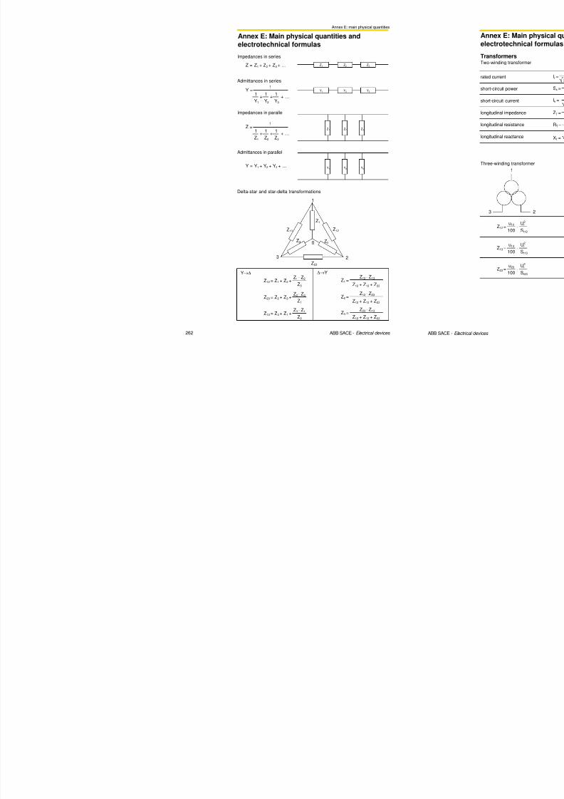
8/3/2019 ABB Electrical Install Ti On Handbook 4th Edition
http://slidepdf.com/reader/full/abb-electrical-install-ti-on-handbook-4th-edition 237/322
96 ABB SACE - Electrical devices
630 630A 4 cond. Al 1024 614.4 614.4 67.5 40.5
630 630A 5 cond. Al 1024 1024 1024 67.5 40.5

8/3/2019 ABB Electrical Install Ti On Handbook 4th Edition
http://slidepdf.com/reader/full/abb-electrical-install-ti-on-handbook-4th-edition 238/322
8/3/2019 ABB Electrical Install Ti On Handbook 4th Edition
http://slidepdf.com/reader/full/abb-electrical-install-ti-on-handbook-4th-edition 239/322

8/3/2019 ABB Electrical Install Ti On Handbook 4th Edition
http://slidepdf.com/reader/full/abb-electrical-install-ti-on-handbook-4th-edition 240/322
3 Protection of electrical equipment
3.1 Protection and switching of lighting circuits
Ur= 400 V Ik= 15 kA
Table 1: Incandescent and halogen lamps
For the selection of a protection device the following verifications shall be carriedout:
- the trip characteristic curve shall be above the turning-on characteristic curveof the lighting device to avoid unwanted trips; an approximate example isshown in Figure1;
- coordination shall exist with the contactor under short-circuit conditions (lightinginstallations are not generally characterized by overloads).
With reference to the above verification criteria, the following tables show themaximum number of lamps per phase which can be controlled by thecombination of ABB circuit-breakers and contactors for some types of lamps,according to their power and absorbed current Ib(*) , for three phase installations
with a rated voltage of 400 V and a maximum short-circuit current of 15 kA.
(
*
)
For calculation see Annex B Calculation of load current Ib

8/3/2019 ABB Electrical Install Ti On Handbook 4th Edition
http://slidepdf.com/reader/full/abb-electrical-install-ti-on-handbook-4th-edition 241/322
104 ABB SACE - Electrical devices
Incandescent/halogen lamps
Circuit-breaker type
Setting PR221 DS
Contactor type
Rated Power [W]
60
100
200
300
500
1000
Rated current Ib [A]
0.27
0.45
0.91
1.37
2.28
4.55
S200M D20
----
A26
57
34
17
11
6
3
S200M D20
----
A26
65
38
19
12
7
4
S200M D25
----
A26
70
42
20
13
8
4
S200M D32
----
A26
103
62
30
20
12
6
S200M D50
----
A30
142
85
42
28
16
8
3 Protection of electrical equipment
3.1 Protection and switching of lighting circuits
Ur= 400 V Ik= 15 kA
Fluorescent lamps non PFC
Circuit-breaker type
Setting PR221 DS
Contactor type
Rated Power [W]
20
40
65
80
100
110
Rated current Ib [A]
0.38
0.45
0.7
0.8
1.15
1.2
S200M D16
A26
40
33
21
18
13
12
S200M D20
A26
44
37
24
21
14
14
S200M D20
A26
50
42
27
23
16
15
S200M D32
A26
73
62
40
35
24
23
S200M D40
A30
100
84
54
47
33
31
Ur= 400 V Ik= 15 kA
Fluorescent lamps PFC
Circuit-breaker type
Setting PR221 DS
Contactor type
Rated Power [W]
20
Rated current Ib [A]
0.18
S200M D25
-- -
A26
83
S200M D25
---
A26
94
S200M D32
---
A26
105
S200M D40
---
A26
155
S200M D63
---
A30
215
Capacitor [µF]
5
Table 2: Fluorescent lamps

8/3/2019 ABB Electrical Install Ti On Handbook 4th Edition
http://slidepdf.com/reader/full/abb-electrical-install-ti-on-handbook-4th-edition 242/322
106 ABB SACE - Electrical devices
40
65
80
100
110
0.26
0.42
0.52
0.65
0.7
58
35
28
23
21
65
40
32
26
24
75
45
36
29
27
107
66
53
43
40
150
92
74
59
55
5
7
7
16
18
3 Protection of electrical equipment
3.1 Protection and switching of lighting circuits
Ur= 400 V Ik= 15 kA
Fluorescent lamps non PFC
Fluorescent lamps PFC
Ur= 400 V Ik= 15 kA
Circuit-breaker type
Setting PR221 DS
Contactor type
Rated Power [W]
150250
400
600
1000
Rated current Ib [A]
1.83
4.4
6.2
10.3
S200M D16
A26
64
3
1
-
S200M D20
A26
74
3
2
1
S200M D20
A26
85
3
2
1
S200M D32
A26
117
4
3
2
S200M D40
A30
159
6
4
3
Circuit-breaker type
Setting PR221 DS
Contactor type
Rated Power [W]
150
Rated current Ib [A]
1
S200M D16
---
A26
13
S200M D20
---
A26
14
S200M D20
---
A26
15
S200M D32
-- -
A26
23
S200M D40
-- -
A30
28
Capacitor [µF]
20
Table 3: High intensity discharge lamps

8/3/2019 ABB Electrical Install Ti On Handbook 4th Edition
http://slidepdf.com/reader/full/abb-electrical-install-ti-on-handbook-4th-edition 243/322
108 ABB SACE - Electrical devices
250
400
600
1000
1.5
2.5
3.3
6.2
8
5
4
-
9
5
4
-
10
6
5
-
15
9
7
4
18
11
8
4
36
48
65
100

8/3/2019 ABB Electrical Install Ti On Handbook 4th Edition
http://slidepdf.com/reader/full/abb-electrical-install-ti-on-handbook-4th-edition 244/322
3 Protection of electrical equipment
3.2 Protection and switching of generators
4 S200 B6
67
9S200 B13
11 S200 B161417
192122
2831
353842
4448
5569 S280 B1008087
100
T2 160
111138
159173
180190208218
T4 250
S280 B80
S200 B32
S200 B50
S200 B63
S200 B10
S200 B25
Srg [kVA] MCB MCCB ACB
T3 250
T4 320
4 S200 B6
6 S200 B8
7 S200 B10
9 S200 B13
11
14 S200 B20
17 S200 B25
19
21
22
28
31
35
38
42
44
48
5569 S280 B100
80
87
100
111
138
T4 250
159
173
180
190
208
218
T2 160
S200 B50
S200 B63
S280 B80
T4 320
T3 250
S200 B32
Srg [kVA] MCB MCCB ACB
S200 B40
S200 B16
The following tables give ABB SACE suggestions for the protection and switchingof generators; the tables refer to 400 V (Table 1), 440 V (Table 2), 500 V (Table 3)and 690 V (Table 4). Molded-case circuit-breakers can be equipped with boththermomagnetic (TMG) as well as electronic releases.
Table 1 400 V Table 2 440 V

8/3/2019 ABB Electrical Install Ti On Handbook 4th Edition
http://slidepdf.com/reader/full/abb-electrical-install-ti-on-handbook-4th-edition 245/322
112 ABB SACE - Electrical devices
1 S D C 0 1 0 0 1 6 F 0 0 0 1
242
277308311346381415436
484554
692727
1730 E3 2500
21802214
22502500
280031503500 E6 6300
T5 400 242
277 T5 400308
311
346
381
415
436
484
554
692
727
865
1730
21802214
2250
2500
2800
3150
3500
T6 800
T5 630
1107
865
T5 630
T6 800
T7 1000
T7 1250*
T7 1600*
X1 630
X1 800*
X1 1000**
X1 1250*X1 1250**
X1 1600**
E3 3200
X1 1250**
E4 4000
E6 5000
T7 1000
1107
T7 1250*
T7 1600*
X1 630
X1 800**
X1 1000**
X1 1600**
E3 2500
E3 3200
E4 3600
E4 4000
E6 5000
* also Isomax CB type S7 can be used for this application** also Emax CB type E1 can be used for this application

8/3/2019 ABB Electrical Install Ti On Handbook 4th Edition
http://slidepdf.com/reader/full/abb-electrical-install-ti-on-handbook-4th-edition 246/322

8/3/2019 ABB Electrical Install Ti On Handbook 4th Edition
http://slidepdf.com/reader/full/abb-electrical-install-ti-on-handbook-4th-edition 247/322

8/3/2019 ABB Electrical Install Ti On Handbook 4th Edition
http://slidepdf.com/reader/full/abb-electrical-install-ti-on-handbook-4th-edition 248/322

8/3/2019 ABB Electrical Install Ti On Handbook 4th Edition
http://slidepdf.com/reader/full/abb-electrical-install-ti-on-handbook-4th-edition 249/322

8/3/2019 ABB Electrical Install Ti On Handbook 4th Edition
http://slidepdf.com/reader/full/abb-electrical-install-ti-on-handbook-4th-edition 250/322

8/3/2019 ABB Electrical Install Ti On Handbook 4th Edition
http://slidepdf.com/reader/full/abb-electrical-install-ti-on-handbook-4th-edition 251/322

8/3/2019 ABB Electrical Install Ti On Handbook 4th Edition
http://slidepdf.com/reader/full/abb-electrical-install-ti-on-handbook-4th-edition 252/322

8/3/2019 ABB Electrical Install Ti On Handbook 4th Edition
http://slidepdf.com/reader/full/abb-electrical-install-ti-on-handbook-4th-edition 253/322

8/3/2019 ABB Electrical Install Ti On Handbook 4th Edition
http://slidepdf.com/reader/full/abb-electrical-install-ti-on-handbook-4th-edition 254/322

8/3/2019 ABB Electrical Install Ti On Handbook 4th Edition
http://slidepdf.com/reader/full/abb-electrical-install-ti-on-handbook-4th-edition 255/322

8/3/2019 ABB Electrical Install Ti On Handbook 4th Edition
http://slidepdf.com/reader/full/abb-electrical-install-ti-on-handbook-4th-edition 256/322

8/3/2019 ABB Electrical Install Ti On Handbook 4th Edition
http://slidepdf.com/reader/full/abb-electrical-install-ti-on-handbook-4th-edition 257/322
3 Protection of electrical equipment
3.4 Protection and switching of transformers
%
100
k
rk
u
II
⋅= [A] (5)
The full voltage three-phase short-circuit current (Ik), at the LV terminals of thetransformer, can be expressed as (assuming that the short-c ircuit power of thenetwork is infinite):
where:uk% is the short-circuit voltage of the transformer, in %.
The protection circuit-breaker must have: (*)
In ≥ Ir;Icu (Ics) ≥ Ik.
If the short-circuit power of the upstream network is not infinite and cable orbusbar connections are present, it is possible to obtain a more precise valuefor Ik by using formula (1), where ZNet is the sum of the impedance of thenetwork and of the impedance of the connection.
MV/LV substation with more than one transformer in parallel For the calculation of the rated current of the transformer, the above applies(formula 4).
The breaking capacity of each protection c ircuit-breaker on the LV side shall be
higher than the short-circuit current equivalent to the short-circuit current ofeach equal transformer multiplied by the number of them minus one.As can be seen from the diagram below, in the case of a fault downstream of atransformer circuit-breaker (circuit-breaker A), the short-circuit current that flowsthrough the circuit-breaker is equal to the contribution of a single transformer.In the case of a fault upstream of the same circuit-breaker, the short-circuit
current that flows is equal to the contribution of the other two transformers inparallel.
(*)
To carry out correct protection against overload it is advisable to use thermometrici h i d i bl i i id

8/3/2019 ABB Electrical Install Ti On Handbook 4th Edition
http://slidepdf.com/reader/full/abb-electrical-install-ti-on-handbook-4th-edition 258/322
138 ABB SACE - Electrical devices
To carry out correct protection against overload it is advisable to use thermometricequipment or other protection devices able to monitor temperature insidetransformers.

8/3/2019 ABB Electrical Install Ti On Handbook 4th Edition
http://slidepdf.com/reader/full/abb-electrical-install-ti-on-handbook-4th-edition 259/322

8/3/2019 ABB Electrical Install Ti On Handbook 4th Edition
http://slidepdf.com/reader/full/abb-electrical-install-ti-on-handbook-4th-edition 260/322

8/3/2019 ABB Electrical Install Ti On Handbook 4th Edition
http://slidepdf.com/reader/full/abb-electrical-install-ti-on-handbook-4th-edition 261/322

8/3/2019 ABB Electrical Install Ti On Handbook 4th Edition
http://slidepdf.com/reader/full/abb-electrical-install-ti-on-handbook-4th-edition 262/322
3 Protection of electrical equipment
3.4 Protection and switching of transformers
1 S D C
0 1 0 0 2 6 F 0 0 0 1
A1 A2 A3
B1 B2 B3
63 A 400 A 800 A
NOTE
The tables refer to the previously specified conditions; the information for theselection of circuit-breakers is supplied only with regard to the current in useand the prospective short-circuit current. For a correct selection, other factorssuch as selectivity, back-up protection, the decision to use limiting circuit-breakers etc. must also be considered. Therefore, it is essential that the design
engineers carry out precise checks.It must also be noted that the short-circuit currents given are determined usingthe hypothesis of 750 MVA power upstream of the transformers, disregardingthe impedances of the busbars or the connections to the circuit-breakers.
Example:
Supposing the need to size breakers A1/A2/A3, on the LV side of the threetransformers of 630 kVA 20/0.4 kV with uk% equal to 4% and outgoing feedercircuit-breakers B1/B2/B3 of 63-400-800 A:

8/3/2019 ABB Electrical Install Ti On Handbook 4th Edition
http://slidepdf.com/reader/full/abb-electrical-install-ti-on-handbook-4th-edition 263/322
148 ABB SACE - Electrical devices
1

8/3/2019 ABB Electrical Install Ti On Handbook 4th Edition
http://slidepdf.com/reader/full/abb-electrical-install-ti-on-handbook-4th-edition 264/322
4 Power factor correction
4.1 General aspects
1
10
0.50Load power factor
R e l a t i v e v o l t a g e d r o p
Cable cross section
1 S D
C 0 1 0 0 3 9 F 0 2 0 1
Active power increase with equal dimensioning factors
1000
s e
0.4 0.5 0.6
0.7 0.8 0.9
original power factor
Figure 1: Relative voltage drop
Figure 2: Transmittable active power
Voltage drop per unit of active power transmitted

8/3/2019 ABB Electrical Install Ti On Handbook 4th Edition
http://slidepdf.com/reader/full/abb-electrical-install-ti-on-handbook-4th-edition 265/322
152 ABB SACE - Electrical devices
1 S D C 0 1 0 0 4 0 F 0 2 0 1
1
10
100
0.70 0.80 0.90 1.00
Improved power factor
A c t i v e P o w e r % i n
c r e a s

8/3/2019 ABB Electrical Install Ti On Handbook 4th Edition
http://slidepdf.com/reader/full/abb-electrical-install-ti-on-handbook-4th-edition 266/322

8/3/2019 ABB Electrical Install Ti On Handbook 4th Edition
http://slidepdf.com/reader/full/abb-electrical-install-ti-on-handbook-4th-edition 267/322
4 Power factor correction
4.2 Power factor connection method
Table 3 shows the values of reactive power for power factor correction of someABB motors, according to the power and the number of poles.
Pr Qc Before PFC After PFC[kW] [kvar] cosϕr Ir [A] cosϕ2 I2 [A]
400V / 50 Hz / 2 poles / 3000 r/min
7.5 2.5 0.89 13.9 0.98 12.7
11 2.5 0.88 20 0.95 18.6
15 5 0.9 26.5 0.98 24.218.5 5 0.91 32 0.98 29.7
22 5 0.89 38.5 0.96 35.8
30 10 0.88 53 0.97 47.9
37 10 0.89 64 0.97 58.8
45 12.5 0.88 79 0.96 72.2
55 15 0.89 95 0.97 87.3
75 15 0.88 131 0.94 122.2
90 15 0.9 152 0.95 143.9
110 20 0.86 194 0.92 181.0
132 30 0.88 228 0.95 210.9
160 30 0.89 269 0.95 252.2
200 30 0.9 334 0.95 317.5
250 40 0.92 410 0.96 391.0
315 50 0.92 510 0.96 486.3
400V / 50 Hz / 4 poles / 1500 r/min
7.5 2.5 0.86 14.2 0.96 12.7
11 5 0.81 21.5 0.96 18.2
15 5 0.84 28.5 0.95 25.3
18.5 7.5 0.84 35 0.96 30.5
22 10 0.83 41 0.97 35.1
30 15 0.83 56 0.98 47.5
37 15 0.84 68 0.97 59.1
45 20 0.83 83 0.97 71.1
Table 3: Reactive power for power factor motor correction

8/3/2019 ABB Electrical Install Ti On Handbook 4th Edition
http://slidepdf.com/reader/full/abb-electrical-install-ti-on-handbook-4th-edition 268/322
158 ABB SACE - Electrical devices
55 20 0.86 98 0.97 86.9
75 20 0.86 135 0.95 122.8
90 20 0.87 158 0.94 145.9
110 30 0.87 192 0.96 174.8
132 40 0.87 232 0.96 209.6
160 40 0.86 282 0.94 257.4
200 50 0.86 351 0.94 320.2
250 50 0.87 430 0.94 399.4
315 60 0.87 545 0.93 507.9

8/3/2019 ABB Electrical Install Ti On Handbook 4th Edition
http://slidepdf.com/reader/full/abb-electrical-install-ti-on-handbook-4th-edition 269/322

8/3/2019 ABB Electrical Install Ti On Handbook 4th Edition
http://slidepdf.com/reader/full/abb-electrical-install-ti-on-handbook-4th-edition 270/322

8/3/2019 ABB Electrical Install Ti On Handbook 4th Edition
http://slidepdf.com/reader/full/abb-electrical-install-ti-on-handbook-4th-edition 271/322

8/3/2019 ABB Electrical Install Ti On Handbook 4th Edition
http://slidepdf.com/reader/full/abb-electrical-install-ti-on-handbook-4th-edition 272/322

8/3/2019 ABB Electrical Install Ti On Handbook 4th Edition
http://slidepdf.com/reader/full/abb-electrical-install-ti-on-handbook-4th-edition 273/322

8/3/2019 ABB Electrical Install Ti On Handbook 4th Edition
http://slidepdf.com/reader/full/abb-electrical-install-ti-on-handbook-4th-edition 274/322

8/3/2019 ABB Electrical Install Ti On Handbook 4th Edition
http://slidepdf.com/reader/full/abb-electrical-install-ti-on-handbook-4th-edition 275/322

8/3/2019 ABB Electrical Install Ti On Handbook 4th Edition
http://slidepdf.com/reader/full/abb-electrical-install-ti-on-handbook-4th-edition 276/322

8/3/2019 ABB Electrical Install Ti On Handbook 4th Edition
http://slidepdf.com/reader/full/abb-electrical-install-ti-on-handbook-4th-edition 277/322

8/3/2019 ABB Electrical Install Ti On Handbook 4th Edition
http://slidepdf.com/reader/full/abb-electrical-install-ti-on-handbook-4th-edition 278/322
5 Protection of human beings
1 S D C 0 1 0 0 4 0 F 0 0 0 1
10-1 s
0.4s
1s
101 s
102 s
103 s
104 s
950 A
T1B160In125
3x(1x50)+1x(1x25)+1G25
IkLG
=3.0 kA
Figure 3: LG Time-Current curves
From the tripping curve (Figure 3), it is clear that the circuit-breaker trips in 0.4 sfor a current value lower than 950 A. As a consequence, the protection againstindirect contact is provided by the same circuit-breaker which protects thecable against short-circuit and overload, without the necessity of using anadditional residual current device.
5.5 TN System

8/3/2019 ABB Electrical Install Ti On Handbook 4th Edition
http://slidepdf.com/reader/full/abb-electrical-install-ti-on-handbook-4th-edition 279/322
180 ABB SACE - Electrical devices
10kA1kA0.1kA

8/3/2019 ABB Electrical Install Ti On Handbook 4th Edition
http://slidepdf.com/reader/full/abb-electrical-install-ti-on-handbook-4th-edition 280/322

8/3/2019 ABB Electrical Install Ti On Handbook 4th Edition
http://slidepdf.com/reader/full/abb-electrical-install-ti-on-handbook-4th-edition 281/322

8/3/2019 ABB Electrical Install Ti On Handbook 4th Edition
http://slidepdf.com/reader/full/abb-electrical-install-ti-on-handbook-4th-edition 282/322
5 Protection of human beings
5.8 Maximum protected length for the protection of human beings
21min)1(2.15.12
8.0kk
Lm
SUI r
k ⋅⋅⋅+⋅⋅⋅⋅
=ρ
⋅ ⋅
21
min)1(2.15.12
8.0kk
Im
SUL
k
r ⋅⋅⋅+⋅⋅⋅⋅
=ρ
⋅ ⋅
210
min)1(2.15.12
8.0kk
Lm
SUIk ⋅⋅
⋅+⋅⋅⋅⋅=
ρ
⋅⋅
21
min
0
)1(2.15.12
8.0kk
Im
SUL
k
⋅⋅⋅+⋅⋅⋅⋅
=ρ
⋅⋅
1 S D C 0 1 0 0 4 4 F
0 0 0 1
Dy
L1L2
L3
PE
PE
PE
REN
Ik L1L2L3
Z
PE
Ik L1L2L3
Neutral not distributed
When a second fault occurs, the formula becomes:
and consequently:
Neutral distributed
Case A: three-phase circuits in IT system with neutral distributedThe formula is:
and consequently:

8/3/2019 ABB Electrical Install Ti On Handbook 4th Edition
http://slidepdf.com/reader/full/abb-electrical-install-ti-on-handbook-4th-edition 283/322
188 ABB SACE - Electrical devices
21
1
0min
)1(2.15.12
8.0kk
Lm
SUI Nk ⋅⋅
⋅+⋅⋅⋅⋅
=
ρ
⋅⋅
21
min1
0
)1(2.15.12
8.0kk
Im
SUL
k
N ⋅⋅⋅+⋅⋅⋅⋅
=ρ
⋅⋅
Case B: three-phase + neutral circuits in IT system with neutral distributed
The formula is:
and consequently:

8/3/2019 ABB Electrical Install Ti On Handbook 4th Edition
http://slidepdf.com/reader/full/abb-electrical-install-ti-on-handbook-4th-edition 284/322
5 Protection of human beings
5.8 Maximum protected length for the protection of human beings
CURVE K K K K K K K K K K K K K K K K K K K K K K
In ≤2 ≤3 4 4.2 5.8 6 8 10 11 13 15 16 20 25 26 32 37 40 41 45 50 63
I3 28 42 56 59 81 84 112 140 154 182 210 224 280 350 364 448 518 560 574 630 700 882
S SPE
1.5 1.5 185 123 92 88 64 62 46 37 34 28 25 23 18 15 14 12 10 9
2.5 2.5 308 205 1 54 146 106 103 77 62 56 47 41 38 31 25 24 19 17 15 15 14
4 4 492 328 246 234 170 164 123 98 89 76 66 62 49 39 38 31 27 25 24 22 20 16
6 6 738 492 369 350 255 246 185 148 134 114 98 92 74 59 57 46 40 37 36 33 30 23
10 10 1 231 820 615 5 84 4 25 4 10 3 08 2 46 2 24 1 89 1 64 1 54 1 23 98 95 77 67 62 60 55 49 39
1 6 1 6 19 69 1 31 3 98 4 9 34 6 8 1 6 56 4 9 2 3 94 3 5 8 3 03 2 63 2 4 6 1 97 1 5 8 1 51 1 2 3 1 06 9 8 9 6 8 8 7 9 6 3
25 16 2401 1601 12011140 830 800 600 480 437 369 320 300 240 192 185 150 130 120 117 107 96 76
CURVE D D D D D D D D D D D D D D D DIn ≤2 3 4 6 8 10 13 16 20 25 32 40 50 63 80 100
I3 40 60 80 120 160 200 260 320 400 500 640 800 1000 1260 1600 2000
S SPE
1.5 1.5 130 86 65 43 32 26 20 16 13 10 8 6
2.5 2.5 216 144 108 72 54 43 33 27 22 17 14 11 9 7
4 4 346 231 173 115 86 69 53 43 35 28 22 17 14 11 9 7
6 6 519 346 259 173 130 104 80 65 52 42 32 26 21 16 13 10
10 10 865 577 432 288 216 173 133 108 86 69 54 43 35 27 22 17
16 16 1384 923 692 461 346 277 213 173 138 111 86 69 55 44 35 28
25 16 1688 1125 844 563 422 338 260 211 169 135 105 84 68 54 42 34
35 16 47 38
Table 2.4: Curve K
Table 2.5: Curve D
TN system MPLby MCB

8/3/2019 ABB Electrical Install Ti On Handbook 4th Edition
http://slidepdf.com/reader/full/abb-electrical-install-ti-on-handbook-4th-edition 285/322
192 ABB SACE - Electrical devices

8/3/2019 ABB Electrical Install Ti On Handbook 4th Edition
http://slidepdf.com/reader/full/abb-electrical-install-ti-on-handbook-4th-edition 286/322

8/3/2019 ABB Electrical Install Ti On Handbook 4th Edition
http://slidepdf.com/reader/full/abb-electrical-install-ti-on-handbook-4th-edition 287/322
5 Protection of human beings
5.8 Maximum protected length for the protection of human beings
CURVE K K K K K K K K K K K K K K K K K K K K K K
In ≤2 ≤3 4 4.2 5.8 6 8 10 11 13 15 16 20 25 26 32 37 40 41 45 50 63
I3 28 42 56 59 81 84 112 140 154 182 210 224 280 350 364 448 518 560 574 630 700 882
S SPE
1.5 1.5 161 107 80 76 55 54 40 32 29 25 21 20 16 13 12 10 9 8
2.5 2 .5 268 178 134 127 92 89 67 54 49 41 36 33 27 21 21 17 14 13 13 12
4 4 428 285 214 204 148 143 107 86 78 66 57 54 43 34 33 27 23 21 21 19 17 14
6 6 642 428 321 306 221 214 161 128 117 99 86 80 64 51 49 40 35 32 31 29 26 20
10 10 1070 713 5 35 5 10 3 69 3 57 2 68 2 14 1 95 1 65 1 43 1 34 1 07 86 82 67 58 54 52 48 43 3416 16 17 12 1 14 1 85 6 8 15 5 90 57 1 4 28 3 42 31 1 2 63 2 28 2 14 17 1 1 37 1 32 10 7 9 3 8 6 84 7 6 6 8 5 4
2 5 1 6 20 88 1 39 2 1 04 4 9 94 7 20 6 96 5 22 4 18 3 80 3 21 2 78 2 61 2 09 1 67 1 61 1 30 1 13 1 04 1 02 9 3 8 4 6 6
CURVE D D D D D D D D D D D D D D D D
In ≤2 3 4 6 8 10 13 16 20 25 32 40 50 63 80 100I3 40 60 80 120 160 200 260 320 400 500 640 800 1000 1260 1600 2000
S SPE
1.5 1.5 112 75 56 37 28 22 17 14 11 9 7 6
2.5 2.5 187 125 94 62 47 37 29 23 19 15 12 9 7 6
4 4 300 200 150 100 75 60 46 37 30 24 19 15 12 10 7 6
6 6 449 300 225 150 112 90 69 56 45 36 28 22 18 14 11 9
10 10 749 499 375 250 187 150 115 94 75 60 47 37 30 24 19 15
16 16 1199 799 599 400 300 240 184 150 120 96 75 60 48 38 30 24
25 16 1462 974 731 487 365 292 225 183 146 117 91 73 58 46 37 29
35 41 33
Table 3.4: Curve KIT system MPLby MCB
Table 3.5: Curve D

8/3/2019 ABB Electrical Install Ti On Handbook 4th Edition
http://slidepdf.com/reader/full/abb-electrical-install-ti-on-handbook-4th-edition 288/322
198 ABB SACE - Electrical devices

8/3/2019 ABB Electrical Install Ti On Handbook 4th Edition
http://slidepdf.com/reader/full/abb-electrical-install-ti-on-handbook-4th-edition 289/322
5 Protection of human beings
5.8 Maximum protected length for the protection of human beings
Table 3.12: Tmax T4-T5-T6 with PR221 - PR222 - PR223Tmax T7 with PR231-PR232-PR331-PR332
IT system MPLby MCCB
T4 T4 T4 T4 T5 T5 T5 T6 T6 T6 T7 T7 T7 T7
In 100 160 250 320 320 400 630 630 800 1000 800 1000 1250 1600
I3 6.5 In 6.5 In 6.5 In 6.5 In 6.5 In 6.5 In 6.5 In 6.5 In 6.5 In 6.5 In 6.5 In 6.5 In 6.5 In 6.5 In
S SPE
1 .5 1 .5
2 .5 2 .5
4 4
6 6 25 16
10 10 42 26 17
16 16 67 42 27 21 21 17
25 16 82 51 33 26 26 20 13 13
35 16 92 58 37 29 29 23 15 15 12 12
50 25 140 87 56 44 44 35 22 22 17 14 17
70 35 196 122 78 61 61 49 31 31 24 20 24 19 16 12
95 50 275 172 110 86 86 69 44 44 34 27 34 27 22 17
120 70 333 208 133 104 104 83 53 53 42 33 42 33 26 21
150 95 4 14 259 166 129 129 104 66 66 52 41 52 41 33 26
185 95 4 21 263 168 132 132 105 67 67 53 42 53 42 33 26
240 120 503 314 201 157 157 126 80 80 63 50 63 50 40 31
300 150 603 377 241 189 189 151 96 96 75 60 75 60 48 37
Note: if the setting of function I is different from the reference value (6.5), the value of the
MPL shall be multiplied by the ratio between the reference value and the set value.

8/3/2019 ABB Electrical Install Ti On Handbook 4th Edition
http://slidepdf.com/reader/full/abb-electrical-install-ti-on-handbook-4th-edition 290/322
202 ABB SACE - Electrical devices
2
LZ R= L +2
XL
kLLL=I Ur
3 Z L
where
ZL
ZL
ZL
ZN
IkLLL
IkLLL
IkLLL
Three-phase fault
T h f lt
6 Calculation of short-circuit current
A short-circuit is a fault of negligible impedance between live conductors havinga difference in potential under normal operating conditions.
6.1 General aspects
In a three-phase circuit the following types of fault may occur:• three-phase fault;• two-phase fault;• phase to neutral fault;
• phase to PE fault.
In the formulas, the following symbols are used:• Ik short-circuit current;• Ur rated voltage;• ZL phase conductor impedance;• ZN neutral conductor impedance;• ZPE protective conductor impedance.The following table briefly shows the type of fault and the relationships betweenthe value of the short-circuit current for a symmetrical fault (three phase) andthe short-circuit current for asymmetrical faults (two phase and single phase) in
case of faults far from generators.
6.2 Fault typologies

8/3/2019 ABB Electrical Install Ti On Handbook 4th Edition
http://slidepdf.com/reader/full/abb-electrical-install-ti-on-handbook-4th-edition 291/322
204 ABB SACE - Electrical devices
kLLLkLLL
L
rkLL II
Z
UI 87.0
2
3
2
===
ZL
ZL
ZL
ZN
IkLL
Two-phase fault

8/3/2019 ABB Electrical Install Ti On Handbook 4th Edition
http://slidepdf.com/reader/full/abb-electrical-install-ti-on-handbook-4th-edition 292/322

8/3/2019 ABB Electrical Install Ti On Handbook 4th Edition
http://slidepdf.com/reader/full/abb-electrical-install-ti-on-handbook-4th-edition 293/322
6 Calculation of short-circuit current
1 S D C 0 1 0
0 5 0 F 0 0 0 1
CB1 CB2 CB3
Fault
1 S D C 0 1 0 0 5 1 F 0 0 0 1
CB1 CB2 CB3
Fault
6.3.3 Calculation of the short-circuit current
To determine the short-circuit current in an installation, both the fault point as
well as the configuration of the system which maximize the short-circuit currentinvolving the device shall be considered. If appropriate, the contribution of themotors shall be taken into account.For example, in the case detailed below, for circuit-breaker CB1, the worstcondition occurs when the fault is right upstream of the circuit-breaker itself. Todetermine the breaking capacity of the circuit-breaker, the contribution of twotransformers in parallel must be considered.
Fault right downstream of CB1
Fault right upstream of CB1(worst condition for CB1)
6.3 Determination of the short-circuit current: “short-circuit power method”

8/3/2019 ABB Electrical Install Ti On Handbook 4th Edition
http://slidepdf.com/reader/full/abb-electrical-install-ti-on-handbook-4th-edition 294/322
210 ABB SACE - Electrical devices
r
kk
U3
SI
⋅
=
r
kk
U2
SI
⋅=
Once the short-circuit power equivalent at the fault point has been determined,the short-circuit current can be calculated by using the following formula:
Three-phase short-circuit
Two-phase short-circuit
6 Calculation of short-circuit current
267cosη
PS
r
rmot=
⋅=
rϕkVA
26.7Su
100S
r
k
ktrafo=⋅= MVA
%
U
LM
A
CB1
B
CB2 CB3
1 S D C 0 1 0 0 5 3 F 0 0 0 1
6.3.4 Examples
The following examples demonstrate the calculation of the short-circuit currentin some different types of installation.
Example 1
Upstream network: Ur = 20000 VSknet = 500 MVA
Transformer: Sr = 1600 kVAuk% = 6%U1r / U2r =20000/400
Motor: Pr = 220 kW
Ikmot /Ir = 6.6cosϕr = 0.9η = 0.917
Generic load: IrL= 1443.4 Acosϕr= 0.9
Calculation of the short-circuit power of different elements
Network: Sknet= 500 MVA
Transformer:
Motor:
Skmot = 6.6.Srmot = 1.76 MVA for the first 5-6 periods (at 50 Hz about 100 ms)
Calculation of the short-circuit current for the selection of circuit-breakers
Selection of CB1
6.3 Determination of the short-circuit current: “short-circuit power method”

8/3/2019 ABB Electrical Install Ti On Handbook 4th Edition
http://slidepdf.com/reader/full/abb-electrical-install-ti-on-handbook-4th-edition 295/322
212 ABB SACE - Electrical devices
For circuit-breaker CB1, the worst condition arises when the fault occurs rightdownstream of the circuit-breaker itself. In the case of a fault right upstream,the circuit-breaker would be involved only by the fault current flowing from themotor, which is remarkably smaller than the network contribution.

8/3/2019 ABB Electrical Install Ti On Handbook 4th Edition
http://slidepdf.com/reader/full/abb-electrical-install-ti-on-handbook-4th-edition 296/322

8/3/2019 ABB Electrical Install Ti On Handbook 4th Edition
http://slidepdf.com/reader/full/abb-electrical-install-ti-on-handbook-4th-edition 297/322

8/3/2019 ABB Electrical Install Ti On Handbook 4th Edition
http://slidepdf.com/reader/full/abb-electrical-install-ti-on-handbook-4th-edition 298/322
6 Calculation of short-circuit current
6.5.3 Calculation of short-circuit current with the algebra of sequences
Without going into the details of a theoretical treatment, it is possible to showthe procedure to semplify and resolve the electrical network under a pre-estabilished fault condition thruogh an example.
Isolated line-to line fault The diagram showing this fault typology and the link between currents andvoltages, may be represented as follows:
By using the given fault conditions and the formula 1), it follows that:
These relationships applied to the three sequence circuits of Figure 3 allow thedefinition of the sequence network equivalent to the three-phase network understudy and representing the initial fault condition. This network may be
represented as follows:
Fault conditions (3)
V2 V3=
I2 =
I1 0=
I3
Fault:
I1
I2
I3V1
V2
V3
-
Figure 4
Vd = ViId = -Ii
Io = 0 therefore Vo = 0
(4)
~
Id
ZdEd
Vd
Figure 5
6.5 Algebra of sequences

8/3/2019 ABB Electrical Install Ti On Handbook 4th Edition
http://slidepdf.com/reader/full/abb-electrical-install-ti-on-handbook-4th-edition 299/322
220 ABB SACE - Electrical devices
Ii
Vi
Zi

8/3/2019 ABB Electrical Install Ti On Handbook 4th Edition
http://slidepdf.com/reader/full/abb-electrical-install-ti-on-handbook-4th-edition 300/322

8/3/2019 ABB Electrical Install Ti On Handbook 4th Edition
http://slidepdf.com/reader/full/abb-electrical-install-ti-on-handbook-4th-edition 301/322
6 Calculation of short-circuit current
6.5 Algebra of sequences
6.5.5 Formulas for the calculation of the fault currents as a function of theelectrical parameters of the plant
Through Table 1 and through the formulas given for the sequence impedancesexpressed as a function of the electrical parameters of the plant components,it is possible to calculate the different short-circuit currents.
In the following example, a network with a MV/LV transformer with delta primarywinding and secondary winding with grounded star point is taken intoconsideration and a line-to-line fault is assumed downstream the cabledistribution line.
ZNET
ZNET
ZNET
ZT
ZL
ZL
ZL
ZN
ZPE
Figure 6
Applying the algebra of sequences:
=Ik2+(Zd Zi)
Ed3.
the impedances relevant to the positive and negative sequences underexamination are:
=Zd Zi= ZNET+ ZT + ZL
considering that =Ed
Ur
3, the following is obtained:
=Ik2+(Zd Zi)
Ed3.=
+(ZNET ZT
Ur
.2 ZL )+
where:

8/3/2019 ABB Electrical Install Ti On Handbook 4th Edition
http://slidepdf.com/reader/full/abb-electrical-install-ti-on-handbook-4th-edition 302/322
226 ABB SACE - Electrical devices
where:
Ur is the rated voltage on the LV sideZT is the impedance of the transformer
ZL is the impedance of the phase conductor
ZNET is the impedance of the upstream network
By making reference to the previous example, it is possible to obtain Table 2below, which gives the expressions for the short-circuit currents according to
the different typologies of fault.
6 Calculation of short-circuit current
Upstream defined power network 0Upstream infinite power network ZNET
Far-from thetransformer
Near thetransformer
Far-from thetransformer
ZL 0, ZPE (o ZN) 0
Near thetransformer
ZL 0, ZPE (o ZN) 0
Ik3 = ZNET3 .Ik3
Ur
( +Z T + )ZL= ZNET3 .Ik3
Ur
( +ZT ) = ZT3 .Ik3
Ur
( +Z L ) = ZT3 .Ik3
Ur
( )
Ik2
=Ik2
Ur
ZNET2 . ( +ZT + )ZL
=Ik2
Ur
ZNET2 .( +Z T)=Ik2
Ur
ZT2 . ( + ZL )=Ik2
Ur
ZT2 . ( )
<Ik2 Ik3 =Ik2 0.87.Ik3 =Ik2 0.87.Ik3 =Ik2 0.87.Ik3
Ik1
=ZNET3 .
Ik1
Ur
( +Z T +ZL23
. +ZPE)=
ZNET3 .
Ik1
Ur
( +ZT23
. )=
ZT3 .
Ik1
Ur
+ ZL( + ZPE )=
ZT3 .
Ik1
Ur
( )
>Ik1 Ik3
ifZNET > 3 . ZPE
>Ik1 Ik3 ≤Ik1 Ik3 =Ik1 Ik3
Table 3
Table 3 below summarizes the relations for the fault currents, taking into accountthe upstream defined or infinite power network values and the distance of thefault from the transformer.
6.5 Algebra of sequences

8/3/2019 ABB Electrical Install Ti On Handbook 4th Edition
http://slidepdf.com/reader/full/abb-electrical-install-ti-on-handbook-4th-edition 303/322
228 ABB SACE - Electrical devices

8/3/2019 ABB Electrical Install Ti On Handbook 4th Edition
http://slidepdf.com/reader/full/abb-electrical-install-ti-on-handbook-4th-edition 304/322
Figure 7 Figure 8
~~
~=
=~
~=
=~
UPS
2) UPS under emergency operating conditions
a)Overload condition:this condition, involving the load-side circuit-breaker only, is supported by thebattery with inverter, which presents an overload condition usually calculablein the following orders of magnitude:1.15 x In for indefinite time1.25 x In for 600 seconds1.5 x In for 60 seconds
2 x In for 1 secondsGenerally, more detailed data can be obtained from the technical information
given by the manufacturer.
b)Short-circuit condition:the maximum current towards the load is limited by the inverter circuit only(with a value from 150 to 200% of the nominal value). The inverter feeds theshort-circuit for a certain period of time, usually limited to some milliseconds,after which the UPS unit disconnects the load leaving it without supply. In thisoperating modality, it is necessary to obtain selectivity between the circuit-breaker on the load side and the inverter, which is quite difficult due to thereduced tripping times of the protection device of the inverter.
Manual bypass
Static bypass
6 Calculation of short-circuit current

8/3/2019 ABB Electrical Install Ti On Handbook 4th Edition
http://slidepdf.com/reader/full/abb-electrical-install-ti-on-handbook-4th-edition 305/322
UPS on-line with static switch UPS off-line: loads directly fed by the network
232 ABB SACE - Electrical devices
Annex A: Calculation tools
A.1 Slide rules
Yellow slide rule: cable sizing
SideDefinition of the current carrying capacity, impedance and voltage drop of cables.
SideCalculation of the short-circuit current for three-phase fault on the load side ofa cable line with known cross section and length.In addition, a diagram for the calculation of the short-circuit current on the loadside of elements with known impedance.

8/3/2019 ABB Electrical Install Ti On Handbook 4th Edition
http://slidepdf.com/reader/full/abb-electrical-install-ti-on-handbook-4th-edition 306/322
234 ABB SACE - Electrical devices
1 S D C 0 0 8 0 5 9 F 0 0 0 1
Annex A: Calculation tools
A.1 Slide rules
Green slide rule: protection coordination
SideSelection of the circuit-breakers when back-up protection is provided.
SideDefinition of the limit selectivity current for the combination of two circuit-breakersin series.

8/3/2019 ABB Electrical Install Ti On Handbook 4th Edition
http://slidepdf.com/reader/full/abb-electrical-install-ti-on-handbook-4th-edition 307/322
236 ABB SACE - Electrical devices
1 S D C 0 0 8 0 6 1 F 0 0 0 1

8/3/2019 ABB Electrical Install Ti On Handbook 4th Edition
http://slidepdf.com/reader/full/abb-electrical-install-ti-on-handbook-4th-edition 308/322
Annex A: Calculation tools
A.2 DOCWIN
• Representation of the curves of circuit-breakers, cables, transformers, motorsand generators.
• Possibility of entering the curve of the utility and of the MV components pointby point, to verify the tripping discrimination of protection devices.
• Verification of the maximum voltage drop at each load.• Verification of the protect ion devices, with control over the setting parameters
of the adjustable releases (both thermomagnetic as well as electronic).
Selection of operating and protection devices
• Automatic selection of protection devices (circuit-breakers and fuses)• Automatic selection of operating devices (contactors and switch disconnectors)
• Discrimination and back-up managed as selection criteria, with discriminationlevel adjustable for each circuit-breaker combination.
• Discrimination and back-up verification also through quick access tocoordination tables.

8/3/2019 ABB Electrical Install Ti On Handbook 4th Edition
http://slidepdf.com/reader/full/abb-electrical-install-ti-on-handbook-4th-edition 309/322
240 ABB SACE - Electrical devices

8/3/2019 ABB Electrical Install Ti On Handbook 4th Edition
http://slidepdf.com/reader/full/abb-electrical-install-ti-on-handbook-4th-edition 310/322

8/3/2019 ABB Electrical Install Ti On Handbook 4th Edition
http://slidepdf.com/reader/full/abb-electrical-install-ti-on-handbook-4th-edition 311/322

8/3/2019 ABB Electrical Install Ti On Handbook 4th Edition
http://slidepdf.com/reader/full/abb-electrical-install-ti-on-handbook-4th-edition 312/322

8/3/2019 ABB Electrical Install Ti On Handbook 4th Edition
http://slidepdf.com/reader/full/abb-electrical-install-ti-on-handbook-4th-edition 313/322

8/3/2019 ABB Electrical Install Ti On Handbook 4th Edition
http://slidepdf.com/reader/full/abb-electrical-install-ti-on-handbook-4th-edition 314/322

8/3/2019 ABB Electrical Install Ti On Handbook 4th Edition
http://slidepdf.com/reader/full/abb-electrical-install-ti-on-handbook-4th-edition 315/322
S=I tk
2√ (1)
k=Qc (B+20)
ln (2)(1+ )θf - θi
B+θiρ20√
Qc (B+20)
ρ20√
By using the formula (1), it is possible to determine the conductor minimumsection S, in the hypothesis that the generic conductor is submitted to anadiabatic heating from a known initial temperature up to a specific final tempe-rature (applicable if the fault is removed in less than 5 s):
where:• S is the cross section [mm2];
• I is the value (r.m.s) of prospect ive fault current for a fault of negligibleimpedance, which can flow through the protective device [A];
• t is the operating time of the protective device for automatic disconnection [s];
k can be evaluated using the tables 2÷7 or calculated according to the formula (2):
where:• Qc is the volumetric heat capacity of conductor material [J/ °Cmm3] at 20 °C;
• B is the reciprocal of temperature coefficient of resistivity at 0 °C for theconductor [°C];
• ρ20 is the electrical resistivity of conductor material at 20 °C [Ωmm];
• θi initial temperature of conductor [°C];• θf final temperature of conductor [°C].
Table 1 shows the values of the parameters described above.
Table 1: Value of parameters for different materials
Material B Qc ρ20
[°C] [J/ °Cmm3] [Ωmm]
Copper 234.5 3.45⋅10-3 17.241⋅10-6 226Aluminium 228 2.5⋅10-3 28.264⋅10-6 148
Lead 230 1.45⋅10-3 214⋅10-6 41
Steel 202 3.8⋅10-3 138⋅10-6 78
Annex D: Calculation of the coefficient k for
the cables (k2S2)

8/3/2019 ABB Electrical Install Ti On Handbook 4th Edition
http://slidepdf.com/reader/full/abb-electrical-install-ti-on-handbook-4th-edition 316/322
254 ABB SACE - Electrical devices
Annex D: Calculation of the coefficient k for
the cables (k2S2)
Annex D: calculation for the cables
Table 5: Values of k for protective conductors as a core incorporated ina cable or bunched with other cables or insulated conductors
Initial
70
90
90
60
85
180
Final
160/140 a
160/140 a
250
200
220
350
Copper
115/103 a
100/86 a
143
141
134
132
AluminiumValue for k
76/68 a
66/57 a
94
93
89
87
Steel
42/37 a
36/31 a
52
51
48
47
Temperature °C b
Conductor insulation
70 °C PVC
90 °C PVC
90 °C thermosetting
60 °C rubber
85 °C rubber
Silicone rubber
Material of conductor
a The lower value applies to PVC insulated conductors of cross section greater than300 mm2 .
b Temperature limits for various types of insulation are given in IEC 60724.
Table 4: Values of k for bare protective conductors in contact withcable covering but not bunched with other cables
Initial
30
30
30
Final
200
150
220
Copper
159
138
166
AluminiumValue for k
105
91
110
Steel
58
50
60
Temperature °C a
Cable covering
PVC
Polyethylene
CSP
Material of conductor
a Temperature limits for various types of insulation are given in IEC 60724.

8/3/2019 ABB Electrical Install Ti On Handbook 4th Edition
http://slidepdf.com/reader/full/abb-electrical-install-ti-on-handbook-4th-edition 317/322
256 ABB SACE - Electrical devices
The International System of Units (SI)
SI Base Units
Quantity Symbol Unit name
Length m metre
Mass kg kilogram
Time s Second
Electric Current A ampere
Thermodynamic Temperature K kelvin
Amount of Substance mol mole
Luminous Intensity cd candela
Metric Prefixes for Multiples and Sub-multiples of Units
Decimal power Prefix Symbol Decimal power Prefix Symbol
1024 yotta Y 10-1 deci d
1021 zetta Z 10-2 centi c
1018 exa E 10-3 milli m
1015 peta P 10-6 mikro µ
1012 tera T 10-9 nano n
109 giga G 10-12 pico p
106
mega M 10-15
femto f103 kilo k 10-18 atto a
102 etto h 10-21 zepto z
10 deca da 10-24 yocto y
Annex E: Main physical quantities and
electrotechnical formulas

8/3/2019 ABB Electrical Install Ti On Handbook 4th Edition
http://slidepdf.com/reader/full/abb-electrical-install-ti-on-handbook-4th-edition 318/322
258 ABB SACE - Electrical devices
Annex E: Main physical quantities and
electrotechnical formulas
Annex E: main physical quantities
Main electrical and magnetic quantities and SI units
Quantity SI unit Other units ConversionSymbol Name Symbol Name Symbol Name
I current A ampere
V voltage V volt
R resistance Ω ohm
G conductance S siemens G = 1/R
X reactance Ω ohm XL = ωL
XC =-1/ ωC
B susceptance S siemens BL = -1/ ωL
BC = ωCZ impedance Ω ohm
Y admittance S siemens
P active power W watt
Q reactive power var reactive voltampere
S apparent power VA volt ampere
Q electric charge C coulomb Ah ampere/hour 1 C = 1 A⋅s1 Ah = 3600 A⋅s
E electric field V/m volt per metrestrength
C electric capacitance F farad 1 F = 1 C/V
H magnetic field A/m ampere per metre
B magnetic induction T tesla G gauss 1 T = 1 V⋅s/m2
1 G = 10-4 T
L inductance H henry 1 H = 1 Ω⋅s
conductor conductivity temperature
resistivity ρρρρρ20 χχχχχ20=1/ρρρρρ20 coefficient ααααα20
[mm2ΩΩΩΩΩ/m] [m/mm2ΩΩΩΩΩ] [K-1]Aluminium 0.0287 34.84 3.8⋅10-3
Brass, CuZn 40 ≤ 0.067 ≥ 15 2⋅10-3
Constantan 0.50 2 -3⋅10-4
Copper 0.0175 57.14 3.95⋅10-3
Gold 0.023 43.5 3.8⋅10-3
Iron wire 0.1 to 0,15 10 to 6.7 4.5⋅10-3
Lead 0.208 4.81 3.9⋅10-3
Magnesium 0.043 23.26 4.1⋅10-3
Resistivity values, conductivity and temperature coefficient at20 °C of the main electrical materials

8/3/2019 ABB Electrical Install Ti On Handbook 4th Edition
http://slidepdf.com/reader/full/abb-electrical-install-ti-on-handbook-4th-edition 319/322
260 ABB SACE - Electrical devices
Manganin 0.43 2.33 4⋅10-6
Mercury 0.941 1.06 9.2⋅10-4
Ni Cr 8020 1 1 2.5⋅10-4
Nickeline 0.43 2.33 2.3⋅10-4
Silver 0.016 62.5 3.8⋅10-3
Zinc 0.06 16.7 4.2⋅10-3
Annex E: Main physical quantities and
electrotechnical formulas
Annex E: main physical quantities
Impedances in series
Admittances in parallel
Z =1
Z1
+1
Z2
+1
Z3
+…
1
Impedances in parallel
Admittances in series
Z2 Z3Z1
Y1 Y2 Y3
Z1 Z2 Z3Z1 + Z2 + Z3 +…Z =
Y =1
Y1
+1
Y2
+1
Y3
+…
1
Y2 Y3Y1Y1 + Y2 + Y3 +…Y =
Delta-star and star-delta transformations
Z12
2Z23
0 Z2
Z1
Z3
Z13
1
3
∆→Y
Z1 =Z12 ⋅ Z13
Z12 + Z13 + Z23
Z12 = Z1 + Z2 +Z1 ⋅ Z2
Z3
Y→∆

8/3/2019 ABB Electrical Install Ti On Handbook 4th Edition
http://slidepdf.com/reader/full/abb-electrical-install-ti-on-handbook-4th-edition 320/322
262 ABB SACE - Electrical devices
Z2 =Z12 ⋅ Z23
Z12 + Z13 + Z23
Z3 =Z23 ⋅ Z13
Z12 + Z13 + Z23
Z23 = Z2 + Z3 +Z2 ⋅ Z3
Z1
Z13 = Z3 + Z1 +Z3 ⋅ Z1
Z2
Captionρ
20resistivity at 20 °C
total length of conductorS cross section of conductor
α20
temperature coefficient of conductor at 20 °C
θ temperature of conductor
ρθ resistivity against the conductor temperatureω angular frequencyf frequencyr resistance of conductor per length unitx reactance of conductor per length unitu
k% short-circuit percentage voltage of the transformer
power loss
single-phase three-phase direct current
∆u =∆U
Ur
⋅ 100
P = U ⋅ I ⋅ cosϕ P = U ⋅ I
Q = U ⋅ I ⋅ sinϕ
S = 3 ⋅ U ⋅ I = P2 + Q2S = U ⋅ I = P2 + Q2
P = 3 ⋅ U ⋅ I ⋅ cosϕ
Q = 3 ⋅ U ⋅ I ⋅ sinϕ
cosϕ =P
S
voltage drop
percentagevoltage drop
active power
reactive powerapparent power
power factor
∆u =∆U
Ur
⋅ 100∆u =∆U
Ur
⋅ 100
–
–
–cosϕ =P
S
∆P = 2 ⋅ ⋅ r ⋅ I2∆P = 3 ⋅ ⋅ r ⋅ I2∆P = 2 ⋅ ⋅ r ⋅ I2
∆U = 2 ⋅ I ⋅ ⋅ (r cosϕ + x sinϕ) 3 ⋅ I ⋅ ⋅ (r cosϕ + x sinϕ)∆U = ∆U = 2 ⋅ I ⋅ ⋅ r
Voltage drop and power
Annex E: Main physical quantities and
electrotechnical formulas
Annex E: Main physical quantities and
electrotechnical formulas
Annex E: main physical quantities

8/3/2019 ABB Electrical Install Ti On Handbook 4th Edition
http://slidepdf.com/reader/full/abb-electrical-install-ti-on-handbook-4th-edition 321/322
k
Sr
rated apparent power of the transformerU
rrated voltage of the transformer
pk% percentage impedance losses of the transformer under short-circuitconditions
264 ABB SACE - Electrical devices
Due to possible developments of standards as well as ofmaterials, the characteristics and dimensions specified inthis document may only be considered binding afterconfirmation by ABB SACE. 1
S D C 0 1 0 0 0 1 D 0 2 0 4
0 3 / 0 6
P r i n t e d i n I t a l y

8/3/2019 ABB Electrical Install Ti On Handbook 4th Edition
http://slidepdf.com/reader/full/abb-electrical-install-ti-on-handbook-4th-edition 322/322
ABB SACE S.p.A.
An ABB Group CompanyL.V. Breakers
Via Baioni, 3524123 Bergamo - ItalyTel.: +39 035.395.111 - Telefax: +39 035.395.306-433
http://www.abb.com