abb extra high voltage surge arresters up to 420kv
TRANSCRIPT
8/10/2019 ABB Extra High Voltage Surge Arresters Up to 420kV
http://slidepdf.com/reader/full/abb-extra-high-voltage-surge-arresters-up-to-420kv 1/96
ABB Surge Arresters — Buyer’s Guide 1Edition 5.1, 2007-04
High Voltage Surge Arresters
Buyer´s Guide
WW.CABLEJOINTS.CO.UK
THORNE & DERRICK UK
TEL 0044 191 490 1547 FAX 0044 477 5371TEL 0044 117 977 4647 FAX 0044 977 5582
WW.THORNEANDDERRICK.CO.UK
8/10/2019 ABB Extra High Voltage Surge Arresters Up to 420kV
http://slidepdf.com/reader/full/abb-extra-high-voltage-surge-arresters-up-to-420kv 2/96
A-1 ABB Surge Arresters — Buyer’s GuideEdition 5.1, 2007-04
Contents
SECTION-PAGE
Introduction A-2
Definitions B-1
Simplified selection procedure C-1
Design features - Porcelain-housedsurge arresters, EXLIM
D-1
Design features - Silicone polymer-housedsurge arresters, PEXLIM
E-1
The PEXLINK concept F-1
Quality control and testing G-1
Zinc oxide surge arresters with siliconepolymer-housed insulator:
PEXLIM R, IEC class 2 H-1
PEXLIM Q, IEC class 3 I-1
PEXLIM P, IEC class 4 J-1
HS PEXLIM P-T, IEC class 4 K-1
HS PEXLIM T-T, IEC class 5 L-1
Zinc oxide surge arresters withporcelain-housed insulator:
EXLIM R, IEC class 2 M-1
EXLIM Q-E, IEC class 3 N-1
EXLIM Q-D, IEC class 3 O-1
EXLIM P, IEC class 4 P-1
EXLIM T, IEC class 5 Q-1
Accessories:
Surge arrester monitor EXCOUNT-II R-1
Surge counter EXCOUNT-A S-1
Purchase order T-1
Index U-1
Customer notes U-3
TechnicalInformation
ProductInformation
Table of contents
Other
8/10/2019 ABB Extra High Voltage Surge Arresters Up to 420kV
http://slidepdf.com/reader/full/abb-extra-high-voltage-surge-arresters-up-to-420kv 3/96
ABB Surge Arresters — Buyer’s Guide A-2Edition 5.1, 2007-04
Introduction
Safe, secure and economic supply of
electricity — with ABB surge arresters
ABB surge arresters are the primary
protection against atmospheric and
switching overvoltages. They are
generally connected in parallel with the
equipment to be protected to divert
the surge current. The active elements
(ZnO-blocks) of ABB surge arresters are
manufactured using a highly non-linear
ceramic resistor material composed
largely of zinc oxide mixed with other
metal oxides and sintered together.
Strong focus on quality at all stages,
from raw material until finished pro-duct, ensure that ABB surge arresters
survive the designed stresses with
ease and with good margins. Different
dimensions permit a large variety of
standard arresters as well as client-
specific solutions as regards protection
levels and energy capability.
This Buyer’s Guide deals with high
voltage surge arresters for standard
AC applications. For other applica-
tions, such as series capacitors prote-
tion, shunt capacitor protection or DC
applications, contact your ABB sales
representative.
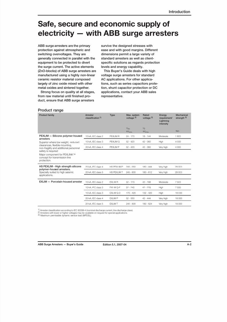
Product rangeProduct family Arrester
classification 1)
Type Max. system
voltage 2)Rated
voltage 2)
Energy
requirement/
Lightning
intensity
Mechanical
strength 3)
UmkV rms
UrkV rms
Nm
PEXLIM — Silicone polymer-housedarresters
Superior where low weight, reducedclearances, flexible mounting,non-fragility and additional personnelsafety is required
Major component for PEXLINK TM concept for transmission lineprotection.
10 kA, IEC class 2 PEXLIM R 24 - 170 18 - 144 Moderate 1 600
10 kA, IEC class 3 PEXLIM Q 52 - 420 42 - 360 High 4 000
20 kA, IEC class 4 PEXLIM P 52 - 420 42 - 360 Very high 4 000
HS PEXLIM - High strength siliconepolymer-housed arresters.Specially suited to high seismicapplications.
20 kA, IEC class 4 HS PEXLIM P 245 - 550 180 - 444 Very high 28 000
20 kA, IEC class 5 HS PEXLIM T 245 - 800 180 - 612 Very high 28 000
EXLIM — Porcelain-housed arrester 10 kA, IEC class 2 EXLIM R 52 - 170 42 - 168 Moderate 7 500
10 kA, IEC class 3 EXLIM Q-E 52 - 245 42 - 228 High 7 500
10 kA, IEC class 3 EXLIM Q-D 170 - 420 132 - 420 High 18 000
20 kA, IEC class 4 EXLIM P 52 - 550 42 - 444 Very high 18 000
20 kA, IEC class 5 EXLIM T 245 - 800 180 - 624 Very high 18 000
1) Arrester classification according to IEC 60099-4 (nominal discharge current, line discharge class).2) Arresters with lower or higher voltages may be available on request for special applications.3) Maximum permissible dynamic service load (MPDSL).
8/10/2019 ABB Extra High Voltage Surge Arresters Up to 420kV
http://slidepdf.com/reader/full/abb-extra-high-voltage-surge-arresters-up-to-420kv 4/96
Definitions
Definitions
Note: The standards referred to here-
under are the latest editions of IEC
60099-4 and ANSI/ IEEE C62.11
Maximum system voltage (Um) The maximum voltage between phases
during normal service.
Nominal discharge current (IEC) The peak value of the lightning current
impulse which is used to classify the
arrester.
Lightning classifying current(ANSI/IEEE) The designated lightning current used to
perform the classification tests.
Rated voltage (Ur ) An arrester fulfilling the IEC standard must
withstand its rated voltage (Ur ) for 10 s
after being preheated to 60 °C and sub-
jected to energy injection as defined in the
standard. Thus, Ur shall equal at least the
10-second TOV capability of an arrester.
Additionally, rated voltage is used as a
reference parameter.
Note! TOV capability of EXLIM andPEXLIM arresters exceeds the IEC
requirements.
Duty-cycle voltage rating (ANSI) The designated maximum permissible
voltage between its terminals at which an
arrester is designed to perform its duty
cycle.
Continuous operating voltageIt is the maximum permissible r.m.s.
power frequency voltage that may be
applied continuously between the arres-
ter terminals. This voltage is defined in
different ways (verified by different test
procedures) in IEC and ANSI.
IEC (Uc )
IEC gives the manufacturer the freedom
to decide Uc. The value is verified in the
operating duty test. Any uneven vol-
tage distribution in the arrester shall be
accounted for.
ANSI (MCOV)
ANSI lists the maximum continuous
operating voltage (MCOV) for all arrester
ratings used in a table. The value is usedin all tests specified by ANSI. MCOV is
less stringent as regards uneven voltage
distribution in an arrester.
Temporary overvoltages (TOV) Temporary overvoltages, as differentiated
from surge overvoltages, are oscillatory
power frequency overvoltages of relatively
long duration (from a few cycles to hours).
The most common form of TOV occurs
on the healthy phases of a system during
an earth-fault involving one or more
phases. Other sources of TOV are load-rejection, energisation of unloaded lines
etc.
The TOV capability of the arresters is
indicated with prior energy stress in the
relevant catalogues.
Residual voltage/Discharge voltage This is the peak value of the voltage that
appears between the terminals of an
arrester during the passage of discharge
current through it. Residual voltagedepends on both the magnitude and
the waveform of the discharge current.
The voltage/current characteristics of the
arresters are given in the relevant catalo-
gues.
Energy capabilityStandards do not explicitly define energy
capability of an arrester. The only measure
specified is the Line Discharge Class in
IEC. Often, this is not enough information
to compare different manufacturers and,
therefore, ABB presents energy capability
also in kJ/kV (Ur ). This is done in 3 diffe-
rent ways:
Two impulses as per IEC clause 8.5.5.
This is the energy that the arrester is sub-
jected to in the switching surge operating
duty test (clause 8.5.5.) while remaining
thermally stable thereafter against the
specified TOV and Uc.
B-1 ABB Surge Arresters — Buyer’s GuideEdition 5, 2004-10
8/10/2019 ABB Extra High Voltage Surge Arresters Up to 420kV
http://slidepdf.com/reader/full/abb-extra-high-voltage-surge-arresters-up-to-420kv 5/96
ABB Surge Arresters — Buyer’s Guide B-2Edition 5.1, 2007-04
Definitions
Note! The altitude correction factors are
13% per 1 000 m (IEC) and 10% per
1000 m (ANSI).
All EXLIM and PEXLIM arresters fully comply
with IEC and ANSI standards for installations
up to 1 000 m, often with a large margin.
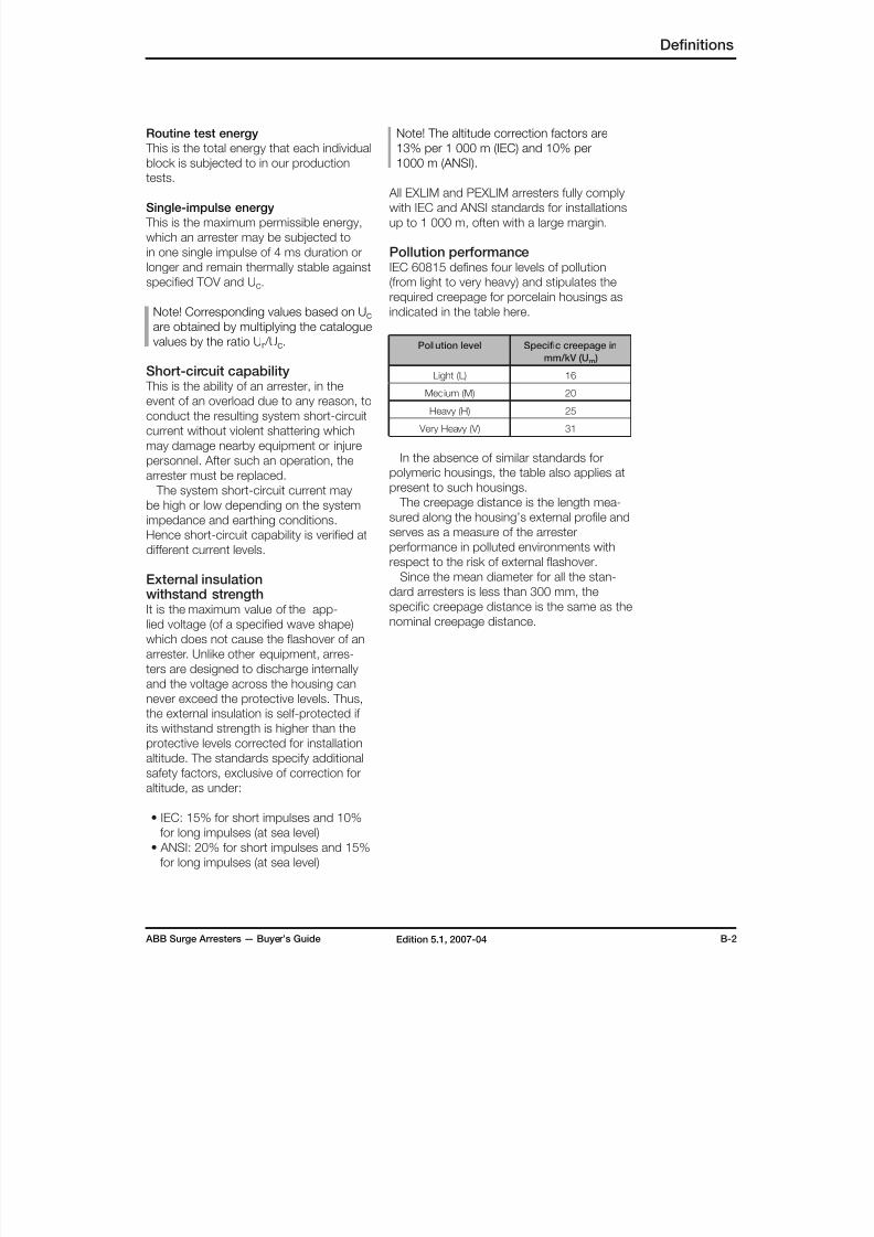
Pollution performanceIEC 60815 defines four levels of pollution
(from light to very heavy) and stipulates the
required creepage for porcelain housings as
indicated in the table here.
Pollution level Specific creepage in
mm/kV (Um )
Light (L) 16
Medium (M) 20
Heavy (H) 25
Very Heavy (V) 31
In the absence of similar standards for
polymeric housings, the table also applies at
present to such housings.
The creepage distance is the length mea-
sured along the housing’s external profile and
serves as a measure of the arrester
performance in polluted environments withrespect to the risk of external flashover.
Since the mean diameter for all the stan-
dard arresters is less than 300 mm, the
specific creepage distance is the same as the
nominal creepage distance.
Routine test energy
This is the total energy that each individual
block is subjected to in our production
tests.
Single-impulse energy
This is the maximum permissible energy,
which an arrester may be subjected to
in one single impulse of 4 ms duration or
longer and remain thermally stable against
specified TOV and Uc.
Note! Corresponding values based on Uc
are obtained by multiplying the catalogue
values by the ratio Ur /Uc.
Short-circuit capability This is the ability of an arrester, in the
event of an overload due to any reason, to
conduct the resulting system short-circuit
current without violent shattering which
may damage nearby equipment or injure
personnel. After such an operation, the
arrester must be replaced.
The system short-circuit current may
be high or low depending on the system
impedance and earthing conditions.
Hence short-circuit capability is verified at
different current levels.
External insulationwithstand strengthIt is the maximum value of the app-
lied voltage (of a specified wave shape)
which does not cause the flashover of an
arrester. Unlike other equipment, arres-
ters are designed to discharge internally
and the voltage across the housing can
never exceed the protective levels. Thus,
the external insulation is self-protected if
its withstand strength is higher than the
protective levels corrected for installation
altitude. The standards specify additional
safety factors, exclusive of correction for
altitude, as under:
• IEC: 15% for short impulses and 10%
for long impulses (at sea level)
• ANSI: 20% for short impulses and 15%
for long impulses (at sea level)
8/10/2019 ABB Extra High Voltage Surge Arresters Up to 420kV
http://slidepdf.com/reader/full/abb-extra-high-voltage-surge-arresters-up-to-420kv 6/96
B-3 ABB Surge Arresters — Buyer’s GuideEdition 5.1, 2007-04
Definitions
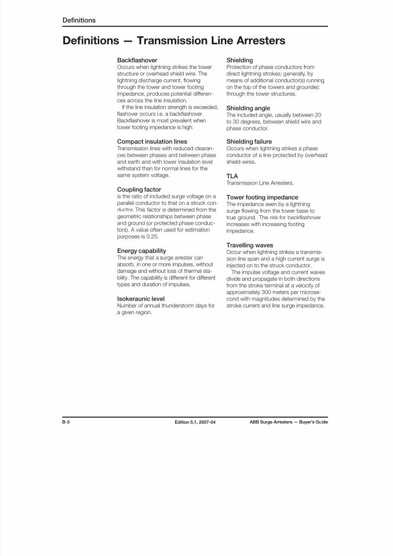
Definitions — Transmission Line Arresters
Backflashover Occurs when lightning strikes the tower
structure or overhead shield wire. The
lightning discharge current, flowingthrough the tower and tower footing
impedance, produces potential differen-
ces across the line insulation.
If the line insulation strength is exceeded,
flashover occurs i.e. a backflashover.
Backflashover is most prevalent when
tower footing impedance is high.
Compact insulation lines Transmission lines with reduced clearan-
ces between phases and between phase
and earth and with lower insulation level
withstand than for normal lines for the
same system voltage.
Coupling factor is the ratio of included surge voltage on a
parallel conductor to that on a struck con-
ductor. This factor is determined from the
geometric relationships between phase
and ground (or protected phase conduc-
tors). A value often used for estimation
purposes is 0.25.
Energy capability The energy that a surge arrester can
absorb, in one or more impulses, without
damage and without loss of thermal sta-
bility. The capability is different for different
types and duration of impulses.
Isokeraunic levelNumber of annual thunderstorm days for
a given region.
ShieldingProtection of phase conductors from
direct lightning strokes; generally, by
means of additional conductor(s) runningon the top of the towers and grounded
through the tower structures.
Shielding angle The included angle, usually between 20
to 30 degrees, between shield wire and
phase conductor.
Shielding failureOccurs when lightning strikes a phase
conductor of a line protected by overhead
shield wires.
TLA Transmission Line Arresters.
Tower footing impedance The impedance seen by a lightning
surge flowing from the tower base to
true ground. The risk for backflashover
increases with increasing footing
impedance.
Travelling wavesOccur when lightning strikes a transmis-
sion line span and a high current surge is
injected on to the struck conductor.
The impulse voltage and current waves
divide and propagate in both directions
from the stroke terminal at a velocity of
approximately 300 meters per microse-
cond with magnitudes determined by the
stroke current and line surge impedance.
8/10/2019 ABB Extra High Voltage Surge Arresters Up to 420kV
http://slidepdf.com/reader/full/abb-extra-high-voltage-surge-arresters-up-to-420kv 7/96
ABB Surge Arresters — Buyer’s Guide C-1Edition 5.1, 2007-04
Selection of arrester
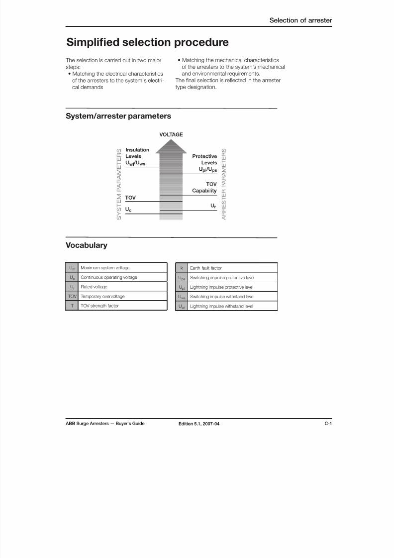
Simplified selection procedure
The selection is carried out in two major
steps:
• Matching the electrical characteristics
of the arresters to the system’s electri-cal demands
System/arrester parameters
Um Maximum system voltage
Uc Continuous operating voltage
Ur Rated voltage
TOV Temporary overvoltage
T TOV strength factor
k Earth fault factor
Ups Switching impulse protective level
Upl Lightning impulse protective level
Uws Switching impulse withstand level
Uwl Lightning impulse withstand level
Vocabulary
• Matching the mechanical characteristics
of the arresters to the system’s mechanical
and environmental requirements.
The final selection is reflected in the arrestertype designation.
8/10/2019 ABB Extra High Voltage Surge Arresters Up to 420kV
http://slidepdf.com/reader/full/abb-extra-high-voltage-surge-arresters-up-to-420kv 8/96
C-2 ABB Surge Arresters — Buyer’s GuideEdition 5.1, 2007-04
Selection of arrester
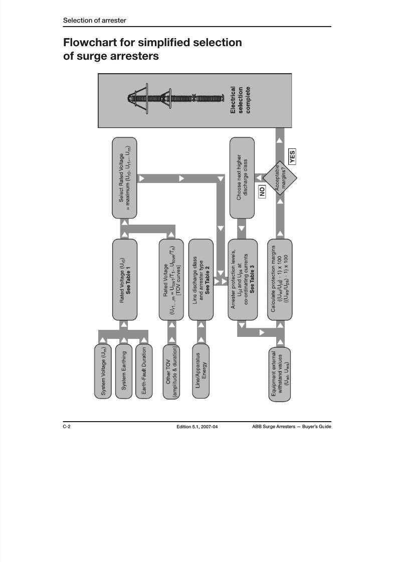
Flowchart for simplified selection
of surge arresters

8/10/2019 ABB Extra High Voltage Surge Arresters Up to 420kV
http://slidepdf.com/reader/full/abb-extra-high-voltage-surge-arresters-up-to-420kv 9/96
ABB Surge Arresters — Buyer’s Guide C-3Edition 5.1, 2007-04
Selection of arrester
SystemEarthing
FaultDura-tion
System VoltageUm (kV)
Min. Rated Voltage, Ur
(kV)
Effective ≤ 1 s ≤ 100 ≥ 0.8 x Um
Effective ≤ 1 s ≥ 123 ≥ 0.72 x Um
Non-effective ≤ 10 s ≤ 170 ≥ 0.91 x Um
≥ 0.93 x Um
(EXLIM T)
Non-effective ≤ 2 h ≤ 170 ≥ 1.11 x Um
Non-effective > 2 h ≤ 170 ≥ 1.25 x Um
Table 1. The table gives a minimum value of the arresterrated voltage (Ur ). In each case, choose the nexthigher standard rating as given in the catalogue.
Note: Do not select a lower value of
Ur than obtained as above unless the
parameters are known more exactly;otherwise the arrester may be over-
stressed by TOV.
Energy capability & linedischarge class
IEC classifies arresters by their nominal
discharge current. For 10 and 20 kA arres-
ters, they are also classified by energy capa-
bility expressed as line discharge class (2
to 5) verified in a long duration current test
and a switching surge operating duty test.
In the latter, the arrester is subjected to twoimpulses of a given amplitude and dura-
tion after which it must be thermally stable
against Uc. The ”class” figure roughly gives
the expected energy absorbed in
kJ/kV (Ur ) per impulse. As seen in Table 2,
the ABB arresters are tested for a much
higher energy absorption capability.
Arrester Type
Linedischarge
class
Energycapability
(2 impulses)kJ/kV (Ur )
Normalapplicationrange (Um )
EXLIM R 2 5.0 ≤ 170 kV
PEXLIM R 2 5.1 ≤ 170 kV EXLIM Q 3 7.8 170 - 420 kV
PEXLIM Q 3 7.8 170 - 420 kV
EXLIM P 4 10.8 362 - 550 kV
PEXLIM P 4 12 362 - 550 kV
HS PEXLIM P 4 10.5 362 - 550 kV
EXLIM T 5 15.4 420 - 800 kV
HS PEXLIM T 5 15.4 420 - 800 kV
Table 2.Energy capability of ABB arresters: The normalapplication range is only a guide. Arresters forhigher class may be required depending on thespecific parameters.
Arrester rated voltage (Ur )For each system voltage, the tables ”Gua-
ranteed protective data” show a range of
Ur and maximum continuous operatingvoltages Uc, all of which are capable of
withstanding the actual continuous ope-
rating voltage (Uca ) with sufficient margin.
Hence, the selection of Ur is only a func-
tion of the applied temporary overvolta-
ges, TOV, (Utov ), taking into account their
amplitudes and duration.
TOV are long-duration, mostly power-
frequency (p.f.) or nearly p.f. voltages,
with or without harmonics, generated
by system events. The arresters must
withstand the heat energy generated by
them.Most commonly, a single or two-phase
earth fault leads to a TOV in the healthy
phase(s) and also in the neutral of Y-
connected transformers. Its amplitude
is determined by the system earthing
conditions and its duration by the fault-
clearance time.
If the earth-fault factor, (k) = Utov /Uca,
is 1.4 or less, the system is considered
to be effectively earthed. Generally, this
implies a solid connection of the neutral to
the earth grid. All other forms of earthingvia an impedance or a non-earthing of the
neutral is considered as non-effective with
k = 1.73
For effectively earthed systems, the fault-
clearance time is generally under 1 s but it
can vary widely among different systems.
The catalogues list the values of TOV
capability for 1 and 10 s duration after
a prior energy stress (as a conservative
approach). For other durations or for spe-
cific TOV conditions, follow the procedure
hereunder:
• Consider each TOV separately.
• From the TOV curves, read off the TOV
strength factor (T) for the time cor-
responding to the fault-clearance time.
• Utov /T gives the min. value of Ur for
withstanding this TOV. Choose the next
higher standard rating.
• The final choice of Ur will be the hig-
hest of the Ur values obtained from the
above calculations for each TOV.
Matching the electrical characteristics
8/10/2019 ABB Extra High Voltage Surge Arresters Up to 420kV
http://slidepdf.com/reader/full/abb-extra-high-voltage-surge-arresters-up-to-420kv 10/96
C-4 ABB Surge Arresters — Buyer’s GuideEdition 5.1, 2007-04
Note! ANSI standards refer to Uwl as BIL
and Uws as BSL.
Margins are normally excellent dueto the low Upl, Ups and also that most
equipment at present have a high Uwl and
Uws. However, depending on the electrical
distance between the arrester and the
protected equipment, the Upl margin is
reduced and thus arresters fail to protect
equipment that is not in the close vicinity
of the arresters (i.e. within their protection
zone). The flexible erection alternatives
for PEXLIM arresters may be of benefit in
reducing the distance effects. Additional
line-entrance arresters may help too. For
more detailed information regarding this,please refer to publications PTHVP/A
2310E and PTHVP/A 2120en.
Note! The ”distance effect” reduction
does not apply to Ups margin since the
front-time of a switching surge impulse
is longer.
It is recommended that the protection
margins (after taking into account the
”distance effect”) should be of the order of
20% or more to account for uncertaintiesand possible reduction in the withstand
values of the protected equipment with
age.
Should the selected arrester type not
give the desired protection margins, the
selection should be changed to an arres-
ter of a higher line discharge class, which
automatically leads to lower Upl.
Note! Do NOT use a lower-than selected
(Ur ) to attempt improve the margins, as
this may lead to unacceptably low TOV
capability.
As an additional assistance in selection,
please refer to the simplified flow chart at
the beginning of this chapter.
Matching the electrical characteristics
Selection of arrester
Though the energy capability is mentioned
in a different manner in ANSI, the normal
range of application as above applies
even for ANSI systems.For specific and special cases, e.g.
capacitor banks, it may be necessary to
calculate the energy capability as shown
in the IEC 60099-5 and other guides.
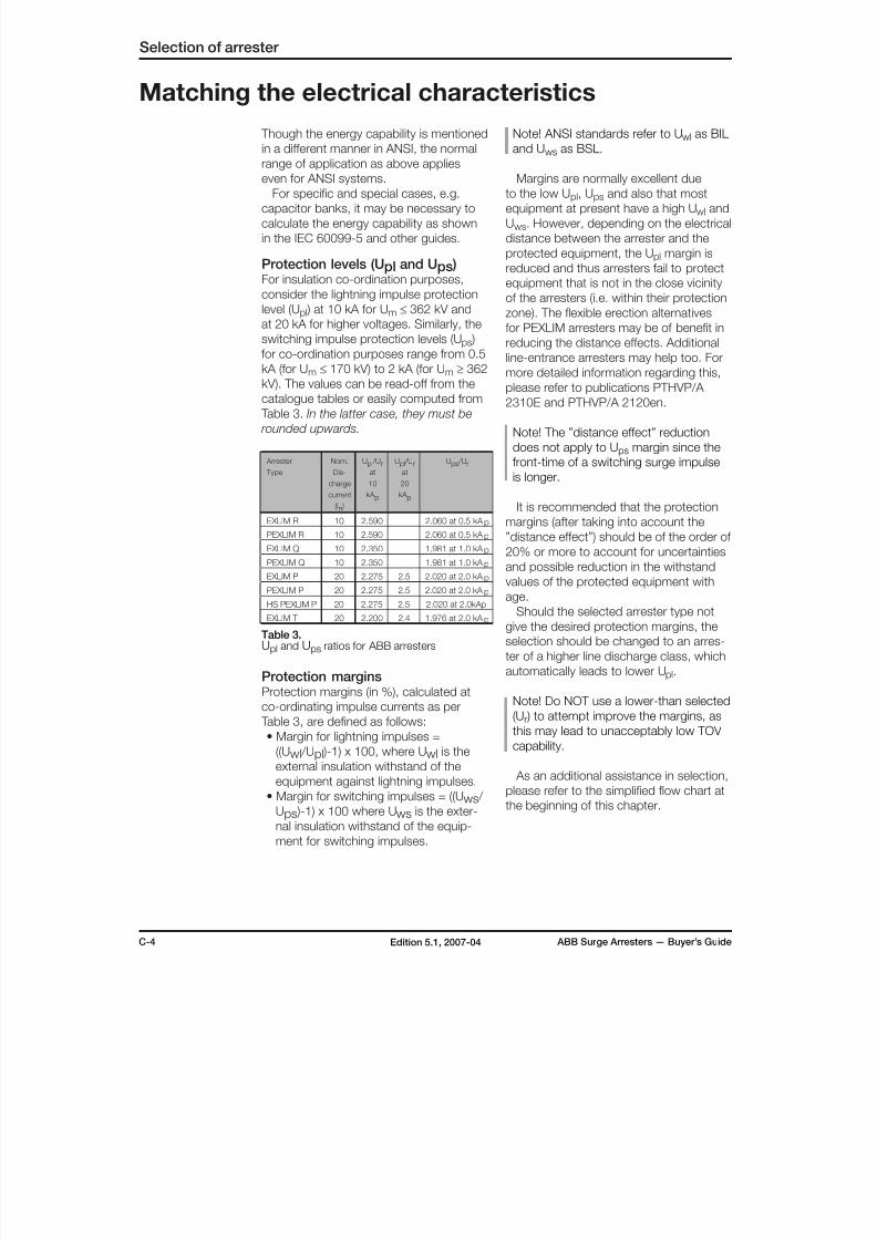
Protection levels (Upl and Ups )For insulation co-ordination purposes,
consider the lightning impulse protection
level (Upl ) at 10 kA for Um ≤ 362 kV and
at 20 kA for higher voltages. Similarly, the
switching impulse protection levels (Ups )
for co-ordination purposes range from 0.5
kA (for Um ≤ 170 kV) to 2 kA (for Um ≥ 362kV). The values can be read-off from the
catalogue tables or easily computed from
Table 3. In the latter case, they must be
rounded upwards.
Arrester
Type
Nom.
Dis-
charge
current
(In )
Upl /Urat
10
kA p
Upl /Urat
20
kA p
Ups /Ur
EXLIM R 10 2.590 2.060 at 0.5 kA p
PEXLIM R 10 2.590 2.060 at 0.5 kA p
EXLIM Q 10 2.350 1.981 at 1.0 kA p
PEXLIM Q 10 2.350 1.981 at 1.0 kA p
EXLIM P 20 2.275 2.5 2.020 at 2.0 kA p
PEXLIM P 20 2.275 2.5 2.020 at 2.0 kA p
HS PEXLIM P 20 2.275 2.5 2.020 at 2.0kAp
EXLIM T 20 2.200 2.4 1.976 at 2.0 kA p
Table 3.Upl and Ups ratios for ABB arresters
Protection marginsProtection margins (in %), calculated at
co-ordinating impulse currents as per
Table 3, are defined as follows:
• Margin for lightning impulses =((Uwl /Upl )-1) x 100, where Uwl is the
external insulation withstand of the
equipment against lightning impulses.
• Margin for switching impulses = ((Uws /
Ups )-1) x 100 where Uws is the exter-
nal insulation withstand of the equip-
ment for switching impulses.
8/10/2019 ABB Extra High Voltage Surge Arresters Up to 420kV
http://slidepdf.com/reader/full/abb-extra-high-voltage-surge-arresters-up-to-420kv 11/96
ABB Surge Arresters — Buyer’s Guide C-5Edition 5.1, 2007-04
Selection of arrester
The varistor column must be suitably
housed to withstand long-term effects of
the system loading and the environmental
stresses.
External creepage distanceIEC 60815 defines the minimum creepage
distances for different environmental
conditions. Select the housing to give the
desired creepage - the same as for the
other equipment in the same location. If
the creepage demand exceeds 31 mm/kV,
please refer to ABB for a special design.
PEXLIM arresters, having a highly
hydrophobic housing, are better suited
for extremely polluted areas than EXLIM
arresters and a lower creepage may be
justified in many cases.
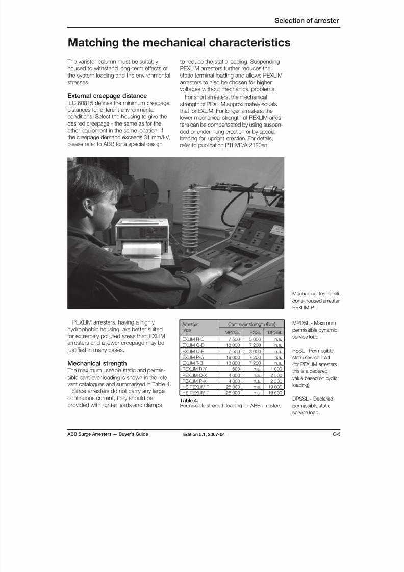
Mechanical strength The maximum useable static and permis-
sible cantilever loading is shown in the rele-
vant catalogues and summarised in Table 4.
Since arresters do not carry any large
continuous current, they should be
provided with lighter leads and clamps
Matching the mechanical characteristics
Mechanical test of sili-
cone-housed arrester
PEXLIM P.
MPDSL - Maximum
permissible dynamic
service load.
PSSL - Permissible
static service load
(for PEXLIM arresters
this is a declared
value based on cyclic
loading).
DPSSL - Declared
permissible static
service load.
to reduce the static loading. Suspending
PEXLIM arresters further reduces the
static terminal loading and allows PEXLIM
arresters to also be chosen for highervoltages without mechanical problems.
For short arresters, the mechanical
strength of PEXLIM approximately equals
that for EXLIM. For longer arresters, the
lower mechanical strength of PEXLIM arres-
ters can be compensated by using suspen-
ded or under-hung erection or by special
bracing for upright erection. For details,
refer to publication PTHVP/A 2120en.
Arrester
type
Cantilever strength (Nm)
MPDSL PSSL DPSSL
EXLIM R-C 7 500 3 000 n.a.EXLIM Q-D 18 000 7 200 n.a.
EXLIM Q-E 7 500 3 000 n.a.
EXLIM P-G 18 000 7 200 n.a.
EXLIM T-B 18 000 7 200 n.a.
PEXLIM R-Y 1 600 n.a. 1 000
PEXLIM Q-X 4 000 n.a. 2 500
PEXLIM P-X 4 000 n.a. 2 500
HS PEXLIM P 28 000 n.a. 19 000
HS PEXLIM T 28 000 n.a. 19 000
Table 4.Permissible strength loading for ABB arresters
8/10/2019 ABB Extra High Voltage Surge Arresters Up to 420kV
http://slidepdf.com/reader/full/abb-extra-high-voltage-surge-arresters-up-to-420kv 12/96
C-6 ABB Surge Arresters — Buyer’s GuideEdition 5.1, 2007-04
Special applicationsPlease consult your nearest ABB repre-
sentative for help in selection of arresters
for special applications such as protectionof shunt or series capacitor banks, cables
and cable-aerial junctions, rotating machi-
nes, traction systems, overhead lines,
HVDC etc. or for non-standard arrester
ratings.
Ordering data for arresters The following information, at a minimum,
is required with your order:
• Quantity and type designation
• Rated voltage
• Type of line terminal
• Type of earth terminal
• Type of surge counter, if any
• Type of insulating base, if any.
(Insulating base is required if surge counter
and/or leakage current measurements
are desired. One base is required for
each arrester).
Ordering exampleBelow is a typical example of an order
with three PEXLIM arresters and its
accessories.
3 pcs. PEXLIM Q192-XV245
Rated voltage 192 kV
Line terminal type 1HSA 410 000-L
Earth terminal type 1HSA 420 000-A
3 pcs. Insulating base type 1HSA 430 000-A
3 pcs. Surge counter type EXCOUNT-A
Note! We recommend that the order
form, in section T-1, be filled-in and
attached to your order to ensure
inclusion of all the important parameters
and commercial conditions.
Selection of arrester
Neutral-ground arrestersFor neutral-ground arresters the recom-
mended rated voltage is approximately
the maximum system voltage divided by√3. The recommended neutral-ground
arresters in the relevant sections are
calculated for unearthed systems with
relatively long fault duration. The electrical
characteristics are identical to standard
catalogue arresters with the correspon-
ding rated voltage. For such arresters,
Uc is zero and they are not subject to
any voltage stress during normal service
conditions. The neutral-ground arresters
should preferably be of the same type as
the phase-ground arresters. For resonant-
earthed systems with long radial linesspecial considerations must be taken. A
higher rated voltage (20% to 40%) than
listed may be necessary.
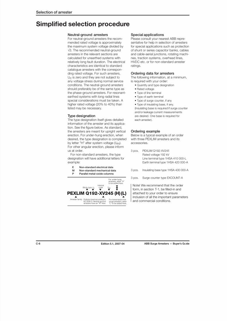
Type designation The type designation itself gives detailed
information of the arrester and its applica-
tion. See the figure below. As standard,
the arresters are meant for upright vertical
erection. For under-hung erection, when
desired, the type designation is completed
by letter ”H” after system voltage (Um ).For other angular erection, please inform
us at order.
For non-standard arresters, the type
designation will have additional letters for
example:
E Non-standard electrical data
M Non-standard mechanical data
P Parallel metal-oxide columns
Simplified selection procedure
PEXLIM Q192-XV245 (H) (L)
Arrester family
Ur
Internalcode UmBlock-type
Pollution level according toIEC 60815. Neutral-groundarresters have an ”N” here.
For under-hungarresters, letter ”H”to be added here.
For transmission linesurge arresters, letter”L” to be added here.
8/10/2019 ABB Extra High Voltage Surge Arresters Up to 420kV
http://slidepdf.com/reader/full/abb-extra-high-voltage-surge-arresters-up-to-420kv 13/96
ABB Surge Arresters — Buyer’s Guide C-7Edition 5.1, 2007-04
Selection of arrester
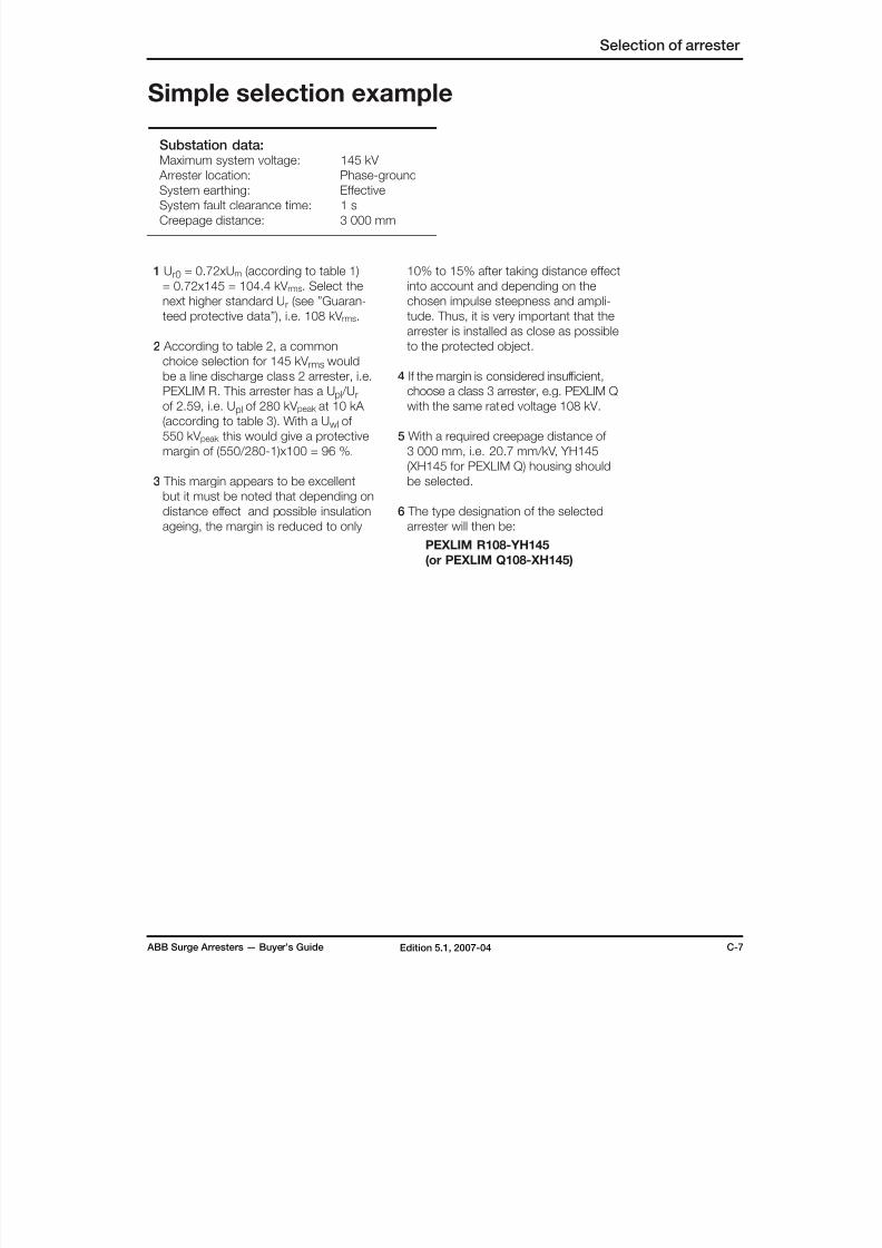
1 Ur0 = 0.72xUm (according to table 1)
= 0.72x145 = 104.4 kV rms. Select the
next higher standard Ur (see ”Guaran-
teed protective data”), i.e. 108 kV rms.
2 According to table 2, a common
choice selection for 145 kV rms would
be a line discharge class 2 arrester, i.e.PEXLIM R. This arrester has a Upl /Ur
of 2.59, i.e. Upl of 280 kV peak at 10 kA
(according to table 3). With a Uwl of
550 kV peak this would give a protective
margin of (550/280-1)x100 = 96 %.
3 This margin appears to be excellent
but it must be noted that depending on
distance effect and possible insulation
ageing, the margin is reduced to only
Simple selection example
Substation data:Maximum system voltage: 145 kV
Arrester location: Phase-ground
System earthing: Effective
System fault clearance time: 1 s
Creepage distance: 3 000 mm
10% to 15% after taking distance effect
into account and depending on the
chosen impulse steepness and ampli-
tude. Thus, it is very important that the
arrester is installed as close as possible
to the protected object.
4 If the margin is considered insufficient,choose a class 3 arrester, e.g. PEXLIM Q
with the same rated voltage 108 kV.
5 With a required creepage distance of
3 000 mm, i.e. 20.7 mm/kV, YH145
(XH145 for PEXLIM Q) housing should
be selected.
6 The type designation of the selected
arrester will then be:
PEXLIM R108-YH145
(or PEXLIM Q108-XH145)
8/10/2019 ABB Extra High Voltage Surge Arresters Up to 420kV
http://slidepdf.com/reader/full/abb-extra-high-voltage-surge-arresters-up-to-420kv 14/96
D-1 ABB Surge Arresters — Buyer’s GuideEdition 5.1, 2007-04
Design features - Porcelain-housed arresters, EXLIM
The design is based on successful
experience of over 65 years, first as
gapped SiC arresters, in all climates
and conditions all over the world.EXLIM arresters live up to their name:
EXcellent voltage LIMiters. The design
is robust and well-matched with the
other apparatus in substations.
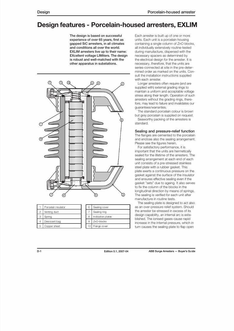
Each arrester is built up of one or more
units. Each unit is a porcelain housing
containing a single column of ZnO blocks,
all individually extensively routine-testedduring manufacture, dispersed with the
necessary spacers as determined by
the electrical design for the arrester. It is
necessary, therefore, that the units are
series-connected at site in the pre-deter-
mined order as marked on the units. Con-
sult the installation instructions supplied
with each arrester.
Longer arresters often require (and are
supplied with) external grading rings to
maintain a uniform and acceptable voltage
stress along their length. Operation of such
arresters without the grading rings, there-fore, may lead to failure and invalidates our
guarantees/warranties.
The standard porcelain colour is brown
but grey porcelain is supplied on request.
Seaworthy packing of the arresters is
standard.
Sealing and pressure-relief function The flanges are cemented to the porcelain
and enclose also the sealing arrangement.
Please see the figures herein.
For satisfactory performance, it isimportant that the units are hermetically
sealed for the lifetime of the arresters. The
sealing arrangement at each end of each
unit consists of a pre-stressed stainless
steel plate with a rubber gasket. This
plate exerts a continuous pressure on the
gasket against the surface of the insulator
and ensures effective sealing even if the
gasket ”sets” due to ageing. It also serves
to fix the column of the blocks in the
longitudinal direction by means of springs.
The sealing is verified for each unit after
manufacture in routine tests.
The sealing plate is designed to act also
as an over-pressure relief system. Should
the arrester be stressed in excess of its
design capability, an internal arc is esta-
blished. The ionised gases cause rapid
increase in the internal pressure, which in
turn causes the sealing plate to flap open
1 Porcelain insulator
2 Venting duct
3 Spring
4 Desiccant bag
5 Copper sheet
Design Porcelain-housed arrester
6 Sealing cover
7 Sealing ring
8 Indication plates
9 ZnO-blocks
10 Flange cover

8/10/2019 ABB Extra High Voltage Surge Arresters Up to 420kV
http://slidepdf.com/reader/full/abb-extra-high-voltage-surge-arresters-up-to-420kv 15/96
ABB Surge Arresters — Buyer’s Guide D-2Edition 5.1, 2007-04
and the ionised gases to flow out through
the venting ducts. Since the ducts at the
two ends are directed towards each other,
this results in an external arc; thus reli-eving the internal pressure and preventing
a violent shattering of the insulator.
Mechanical Strength The mechanical strength of the housing,
i.e. maximum permissible dynamic service
load (MPDSL), is defined in accordance
with IEC 60099-4. Thus the fracture
moment is generally 120% of the spe-
cified figure. The insulating base (when
supplied) matches the strength of the
housing.
The permissible static service load(PSSL) i.e. continuous moment should be
limited to 40% of the MPDSL in accor-
dance with IEC 60099-4.
Arresters with mechanical strength
higher than listed are quoted on request.
Mechanical loadingHorizontal (cantilever) load
The maximum permissible continuous
horizontal load is calculated as the maxi-
mum continuous (static) moment divided
by the distance between the base of thearrester and the centre of the terminal
load.
The continuous current through an
arrester is of the order of a few mA.
Hence, using a lighter terminal clamp
and/or connecting the arrester by a lighter
tee-off considerably reduces the demand
for mechanical strength.
Installation, maintenanceand monitoringStandard EXLIM arresters are intended
for vertical, upright erection on a structure
and require no bracing. Special EXLIM
arresters for suspension, inverted moun-
ting or other angular erection are available
on request.
EXLIM arresters are easy to install
following the instructions packed with
each arrester. Installation does not need
any special tools or instruments. Properly
chosen and installed arresters are prac-
tically maintenance-free for their lifetime
and do not need any monitoring. Howe-ver, if such monitoring is demanded, it
is easily performed online by using the
EXCOUNT-II with it’s built-in features for
correctly measuring the resistive leakage
current.
Cutaway view of a typical EXLIM unit showing
the internal arrangements designed to mini-
mise partial discharge.
Porcelain-housed arrester Design
8/10/2019 ABB Extra High Voltage Surge Arresters Up to 420kV
http://slidepdf.com/reader/full/abb-extra-high-voltage-surge-arresters-up-to-420kv 16/96
E-1 ABB Surge Arresters — Buyer’s GuideEdition 5.1, 2007-04
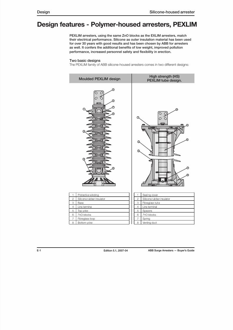
Design features - Polymer-housed arresters, PEXLIM
Design Silicone-housed arrester
1 Protective winding
2 Silicone rubber insulator
3 Base
4 Line terminal
5 Top yoke
6 ZnO-blocks
7 Fibreglass loop
8 Bottom yoke
PEXLIM arresters, using the same ZnO blocks as the EXLIM arresters, match
their electrical performance. Silicone as outer insulation material has been used
for over 30 years with good results and has been chosen by ABB for arresters
as well. It confers the additional benefits of low weight, improved pollutionperformance, increased personnel safety and flexibility in erection.
Two basic designs The PEXLIM family of ABB silicone-housed arresters comes in two different designs:
Moulded PEXLIM designHigh strength (HS)
PEXLIM tube design.
1 Sealing cover
2 Silicone rubber insulator
3 Fibreglass tube
4 Line terminal
5 Spacers
6 ZnO-blocks
7 Spring
8 Venting duct
8/10/2019 ABB Extra High Voltage Surge Arresters Up to 420kV
http://slidepdf.com/reader/full/abb-extra-high-voltage-surge-arresters-up-to-420kv 17/96
ABB Surge Arresters — Buyer’s Guide E-2Edition 5.1, 2007-04
Silicone-housed arrester Design
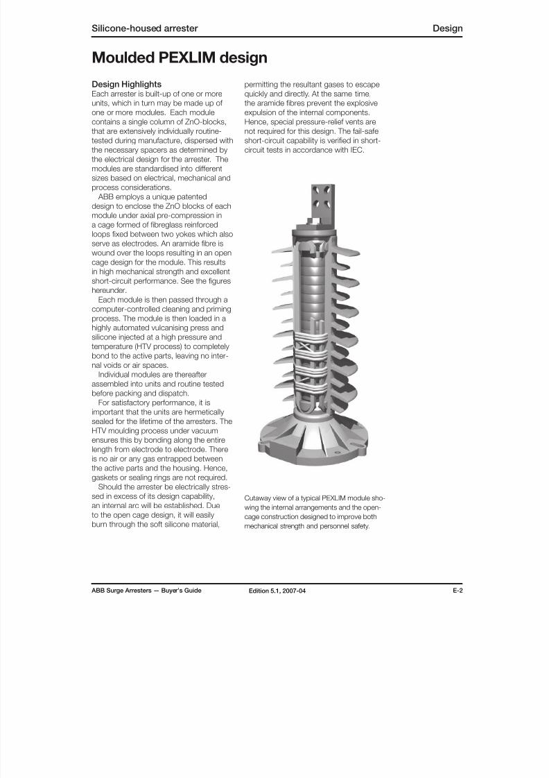
Cutaway view of a typical PEXLIM module sho-
wing the internal arrangements and the open-
cage construction designed to improve both
mechanical strength and personnel safety.
Design HighlightsEach arrester is built-up of one or more
units, which in turn may be made up of
one or more modules. Each modulecontains a single column of ZnO-blocks,
that are extensively individually routine-
tested during manufacture, dispersed with
the necessary spacers as determined by
the electrical design for the arrester. The
modules are standardised into different
sizes based on electrical, mechanical and
process considerations.
ABB employs a unique patented
design to enclose the ZnO blocks of each
module under axial pre-compression in
a cage formed of fibreglass reinforced
loops fixed between two yokes which alsoserve as electrodes. An aramide fibre is
wound over the loops resulting in an open
cage design for the module. This results
in high mechanical strength and excellent
short-circuit performance. See the figures
hereunder.
Each module is then passed through a
computer-controlled cleaning and priming
process. The module is then loaded in a
highly automated vulcanising press and
silicone injected at a high pressure and
temperature (HTV process) to completelybond to the active parts, leaving no inter-
nal voids or air spaces.
Individual modules are thereafter
assembled into units and routine tested
before packing and dispatch.
For satisfactory performance, it is
important that the units are hermetically
sealed for the lifetime of the arresters. The
HTV moulding process under vacuum
ensures this by bonding along the entire
length from electrode to electrode. There
is no air or any gas entrapped between
the active parts and the housing. Hence,
gaskets or sealing rings are not required.
Should the arrester be electrically stres-
sed in excess of its design capability,
an internal arc will be established. Due
to the open cage design, it will easily
burn through the soft silicone material,
permitting the resultant gases to escape
quickly and directly. At the same time,
the aramide fibres prevent the explosive
expulsion of the internal components.Hence, special pressure-relief vents are
not required for this design. The fail-safe
short-circuit capability is verified in short-
circuit tests in accordance with IEC.
Moulded PEXLIM design

8/10/2019 ABB Extra High Voltage Surge Arresters Up to 420kV
http://slidepdf.com/reader/full/abb-extra-high-voltage-surge-arresters-up-to-420kv 18/96
E-3 ABB Surge Arresters — Buyer’s GuideEdition 5.1, 2007-04
Design Silicone-housed arrester
In special cases with very high demands
for mechanical strength, the moulded
design may not provide the optimal solu-
tion (particularly at system voltages above420kV). Instead, what is required is a
mix between the features of the standard
EXLIM and the moulded PEXLIM designs.
The HS (High strength) PEXLIM tube
design provides this by offering com-
parable mechanical strength to EXLIM
arresters, but with much less mass. The
seismic and pollution performance is in
line with the moulded PEXLIM arresters
and thus superior to conventional porce-
lain designs.
Design highlights The basic concept is the replacement of
the porcelain housing used with EXLIM
arresters by a fibreglass tube housing
onto which the silicone sheds are vulca-
nised. The metal flanges are integrated
onto the tube prior to the vulcanising pro-
cess. The internal arrangement and the
pressure-relief devices are similar to those
for EXLIM arresters.
For satisfactory performance, it is
important that the units are hermetically
sealed for the lifetime of the arresters. The sealing arrangement at each end of
each unit is shown in the figure hereunder
and consists of a pre-stressed stainless
steel plate with a rubber gasket. This
plate exerts a continuous pressure on
the gasket against the inner surface of
the flanges and ensures effective sealing
even if the gasket “sets” due to ageing. It
also serves to fix the column of the blocks
in the longitudinal direction by means of
heavy spring washers.
To maintain the interior free of any humi-
dity, the unit is evacuated after the sealing
plate and gaskets are fitted and then filled
with dry air at low dew point. Additionally,
a small bag of a desiccant is placed in
each unit during assembly. Sealing is veri-
fied for each unit after manufacture during
routine tests.
High strength (HS) PEXLIM tube design
The sealing plate is designed to also
act as an over-pressure relief system.
Should the arrester be electrically stres-
sed in excess of its design capability,an internal arc is established. The ioni-
sed gases cause a rapid increase in the
internal pressure, which in turn causes
the sealing plate to flap open and the
ionised gases to flow out through the
venting ducts. Since the ducts at the two
ends are directed towards each other, this
results in an external arc; thus relieving the
internal pressure and preventing a violent
shattering of the insulator. The successful
operation of the pressure-relief device is
verified in short-circuit tests in accordance
with IEC.
Cutaway view of a typical HS PEXLIM unit
showing the internal arrangements.
8/10/2019 ABB Extra High Voltage Surge Arresters Up to 420kV
http://slidepdf.com/reader/full/abb-extra-high-voltage-surge-arresters-up-to-420kv 19/96
ABB Surge Arresters — Buyer’s Guide E-4Edition 5.1, 2007-04
Silicone-housed arrester Design
Silicone as an Insulator
All PEXLIM arresters utilise silicone for
the external insulation. Silicone rubber is
highly hydrophobic and resistant to UV
radiation and has been shown to be thebest insulation (compared to both porce-
lain and other polymers) based on world
wide independent laboratory and field
tests. ABB uses special fillers to enhance
these properties as well as giving it high
pollution resistance, tracking resistance
and fire-extinguishing features. The
silicone housing is available only in grey
colour. For additional information, please
refer to publication PTHVP/A 2120en.
Mechanical Strength
Present standards lack suitable defini-tions and tests regarding the mechanical
strength of composite polymeric material.
A “damage limit” has nevertheless been
defined in IEC60099-4 as the lowest value
of force perpendicular to the longitudinal
axis leading to mechanical failure. Simi-
larly, the “maximum permissible dynamic
service load” (MPDSL) is the greatest
dynamic force allowed to be applied
during service without causing any
mechanical damage to the arrester.
All PEXLIM designs exhibit very highstrength under tensile or compression
loading; hence it is the cantilever loading
that is of interest. To be applicable to
different arrester lengths, the loading is
given in terms of bending moment in this
guide. Furthermore, since standard multi-
unit PEXLIM arresters are built with units
of equal strength, the bending moment at
the base of the arrester is the only figure
of interest.
Due to their flexible construction,
PEXLIM arresters may exhibit a visible
deflection at the line-end of the arrester
under maximum loading. Such deflec-
tion is limited by our declared value for
permissible static service load (DPSSL)
given in Table 4. This maximum recom-
mended continuous loading ensures that
the electrical and/or mechanical functions
of the arrester are not impaired in any way,
even during long-term cyclic loading. This
value is comparable with the permissible
static service load for porcelain arresters(PSSL).
If the permissible bending moment
for a certain arrester appears insufficient
for a given loading, consider one of the
following methods to reduce the loading
demand.
• Use lighter terminal clamps and/or ligh-
ter tee-offs for arresters. In contrast to
the current capability (and thus the size
of clamps and conductors) required for
other substation equipment, the con-
tinuous current through an arrester is
of the order of only a few mA. Hence,
using lighter terminal clamp and/or
connecting the arresters by lighter tee-
offs considerably reduce the demand
for mechanical strength.
Use another erection alternative (sus-
pension, under-hung, etc). Since
PEXLIM arresters are very light com-
pared to equivalent porcelain-housed
arresters, they permit innovative erection
alternatives, which could further reducethe bending moment demands; particu-
larly in the case of the moulded design
PEXLIM. Refer publication PTHVP/A
2120en. This in turn can lead to the
additional benefit of lighter structures
with subsequent reduced costs, or even
the complete elimination of the need for
a separate structure at all.
Pedestal-mounted long arresters with
mechanical strength higher than listed
may be quoted on request.
The line terminal and the insulating base
(when supplied) match or exceed the
strength of the arrester housing.
8/10/2019 ABB Extra High Voltage Surge Arresters Up to 420kV
http://slidepdf.com/reader/full/abb-extra-high-voltage-surge-arresters-up-to-420kv 20/96
E-5 ABB Surge Arresters — Buyer’s GuideEdition 5.1, 2007-04
Design Silicone-housed arrester
Installation, maintenance and monitoring
Standard PEXLIM arresters are intended
for vertical, upright erection on a structure
and require no bracing. Special PEXLIM
arresters for suspension, inverted moun-
ting or other angular erection are available
on request.
There are two standard ranges of the
moulded design PEXLIM arresters for the
following erection alternatives:
• Vertical & upright erection mounted on
a structure or suspended by the line
terminal from a conductor. Such arres-
ters may also be used for “positive”
angular erection (above horizontal).
• Vertical and inverted erection for moun-ting under a structure, e.g. a gantry.
Such arresters may also be used for
“negative” angular erection (below hori-
zontal).
All PEXLIM arresters are easy to install fol-
lowing the instructions packed with each
arrester. Installation does not need any
special tools or instruments.
The units of multiple-unit arresters must
be series-connected at site in a pre-
determined order as marked on the unitsand explained in the instructions that are
packed in each case. An incorrect assem-
bly may lead to failure and invalidates our
warranty.
The design of long arresters often
requires external grading rings to maintain
a uniform and acceptable voltage stress
along their length. Such rings are included
in the delivery of arresters. Installation or
operation of such arresters without these
grading rings may lead to failure and inva-
lidates our warranty.
Properly chosen and installed arrestersare practically maintenance-free for their
lifetime and do not need any monitoring.
However, if such monitoring is demanded,
it is easily performed online by using the
EXCOUNT-II with it’s built-in features for
correctly measuring the resistive leakage
current. More information is available in
the chapter dealing with this counter.

8/10/2019 ABB Extra High Voltage Surge Arresters Up to 420kV
http://slidepdf.com/reader/full/abb-extra-high-voltage-surge-arresters-up-to-420kv 21/96
8/10/2019 ABB Extra High Voltage Surge Arresters Up to 420kV
http://slidepdf.com/reader/full/abb-extra-high-voltage-surge-arresters-up-to-420kv 22/96
F-2 ABB Surge Arresters — Buyer’s GuideEdition 5.1, 2007-04
PEXLINK Transmission line surge arresters
ABB’s philosophy is to provide pro-
tection for line insulation at selected
locations by using standard available
components. The main item is thegapless silicone polymer-housed arres-
ter, PEXLIM, with metal-oxide (MO)
active elements. Such arresters have
been used for many years for protec-
tion of equipment in substations and
hence their protective performance is
well-known.
The low weight permits installation on
existing structures and the polymer
housing gives increased safety of the line
equipment as well as people and animals
which may be in the vicinity of the lines
during overstress conditions.
With regard to lightning energy, line
arresters are exposed to more severe
conditions than arresters placed in sub-
stations. The latter are benefited by the
reduction of surge steepness due to line
corona effect and reduction in surge amp-litude as the lightning current finds parallel
paths through shielding wires, flashover
and parallel lines. Thus, it is necessary to
ensure that the MO blocks of the TLA are
not under-dimensioned from energy and
current point-of-view. A computer pro-
gram is used to determine the optimum
number of locations (generally where the
footing impedance is high) and to calcu-
ABB´s protection philosophy
late the arrester stresses at each of the
chosen locations.
The design permits installation using
standard transmission-line hardwarenormally available locally. The design
also permits mounting at different angles
based on tower geometry and conductor
spacing.
If very high availability is desired, a very
large number of locations may have to be
protected, mainly due to the unpredicta-
ble nature of lightning. In such a case it
may not be economically justified to select
arresters with ”sufficient energy capability”
and instead a higher failure rate may be
acceptable.
To ensure quick, safe, automatic and
controlled disconnection of a failed arres-
ter, ABB uses a special disconnecting
device with a suitable link, often in the
earthing circuit of the arresters.
The earth lead is designed to withstand
the short-circuit currents and the discon-
necting device is tested to ensure nofalse operations. Thus, at a failure, the
tripped line does not have to be locked-
out and attended to immediately.
By moulding the silicone polymer hou-
sing on the active MO elements directly,
internal atmosphere is eliminated and with
it the risk of ingress of moisture which
in the past has been established as the
major cause of arrester failures in service.
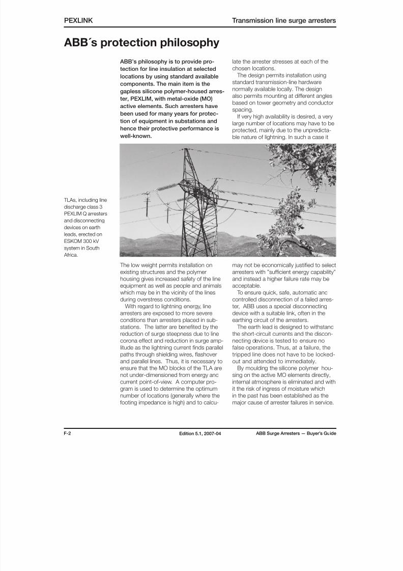
TLAs, including line
discharge class 3
PEXLIM Q arresters
and disconnecting
devices on earth
leads, erected on
ESKOM 300 kV
system in South
Africa.
8/10/2019 ABB Extra High Voltage Surge Arresters Up to 420kV
http://slidepdf.com/reader/full/abb-extra-high-voltage-surge-arresters-up-to-420kv 23/96
ABB Surge Arresters — Buyer’s Guide F-3Edition 5.1, 2007-04
Transmission line surge arresters PEXLINK
Increased line availabilityBy locating the PEXLINK on sections of
lines with high footing impedance towers
and one additional low footing-impedancetower at each end of the section, PEXLINK
protects existing shielded and non-shielded
lines from abnormal lightning surges (fre-
quent or high amplitudes) and reduces the
outages.
The reduced outages are beneficial also
indirectly in that sensitive equipment is not
damaged and the circuit breakers over-
haul interval can be increased. Thus, total
maintenance costs are also reduced.
This protection may be used for all system
voltages where the stated abnormal
conditions exist. Arresters with mode-rate energy capability are often sufficient.
However, the high-current capability must
be large and distribution-type arresters
may not be suitable.
Application
For long EHV lines, surge arresters usu-
ally are located at line-ends. In addition,
by locating arresters at one or more
points along the line e.g. at midpoint or1/3 and 2/3 line length switching surge
overvoltages and thus line insulation
requirements could be limited without
using preinsertion resistors. Arresters
used for this type of application should
be designed for high energy capabi-
lity. Usually a class 2 or 3 arrester will
be sufficient out on the line but higher
arrester classes may be necessary at
the receiving end of the line.
Compact-insulation lines
Arresters placed in parallel with line insula-tors permit a large degree of compacting
of a transmission line with lower right-of-
way costs as a result.
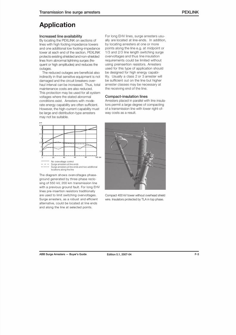
Compact 400 kV tower without overhead shield
wire. Insulators protected by TLA in top phase.
The diagram shows overvol tages phase-
ground generated by three-phase reclo-
sing of 550 kV, 200 km transmission line
with a previous ground fault. For long EHV
lines pre-insertion resistors traditionally
are used to limit switching overvoltages.
Surge arresters, as a robust and efficientalternative, could be located at line ends
and along the line at selected points.
No overvoltage controlSurge arresters at line endsSurge arresters at line ends and two additionallocations along the line
8/10/2019 ABB Extra High Voltage Surge Arresters Up to 420kV
http://slidepdf.com/reader/full/abb-extra-high-voltage-surge-arresters-up-to-420kv 24/96
F-4 ABB Surge Arresters — Buyer’s GuideEdition 5.1, 2007-04
Line upgrading The existing insulation level of a line, when
suitably protected by arresters, may be
upgraded for service at a higher systemvoltage leading to greater power transfer
without much additional capital cost.
Extended station protectionBy locating arresters on towers near a sub-
station, the risk of backflashovers near the
station is eliminated. This results in reduc-
tion of steepness and amplitude of inco-
ming travelling waves, thus improving the
protection performance of station arresters
and eliminating the need for additional
expensive metal-enclosed arresters even
for large GIS.
PEXLINK Transmission line surge arresters
Application
Substitute for shield wiresIn cases where provision of shield wires is
not practical physically or is very expen-
sive, e.g. very long spans, very hightowers etc., arresters are a good and
economical substitute.
Arresters located in all phases on each
tower eliminate the need for both shield
wires and good footing impedance and
may be economically justified in cases
where the cost of reduction in footing
impedance and the cost of overhead
shield wire are very high.
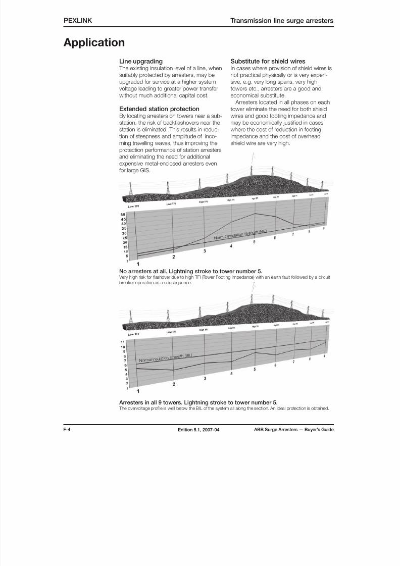
No arresters at all. Lightning stroke to tower number 5. Very high risk for flashover due to high TFI (Tower Footing Impedance) with an earth fault followed by a circuit
breaker operation as a consequence.
Arresters in all 9 towers. Lightning stroke to tower number 5. The overvoltage profile is well below the BIL of the system all along the section. An ideal protection is obtained.
Norma l insu la t ion s treng t h
( BI L )
N o r ma l i n s u la t i o n s t r e n
g t h ( B I L )
8/10/2019 ABB Extra High Voltage Surge Arresters Up to 420kV
http://slidepdf.com/reader/full/abb-extra-high-voltage-surge-arresters-up-to-420kv 25/96
ABB Surge Arresters — Buyer’s Guide F-5Edition 5.1, 2007-04
Transmission line surge arresters PEXLINK
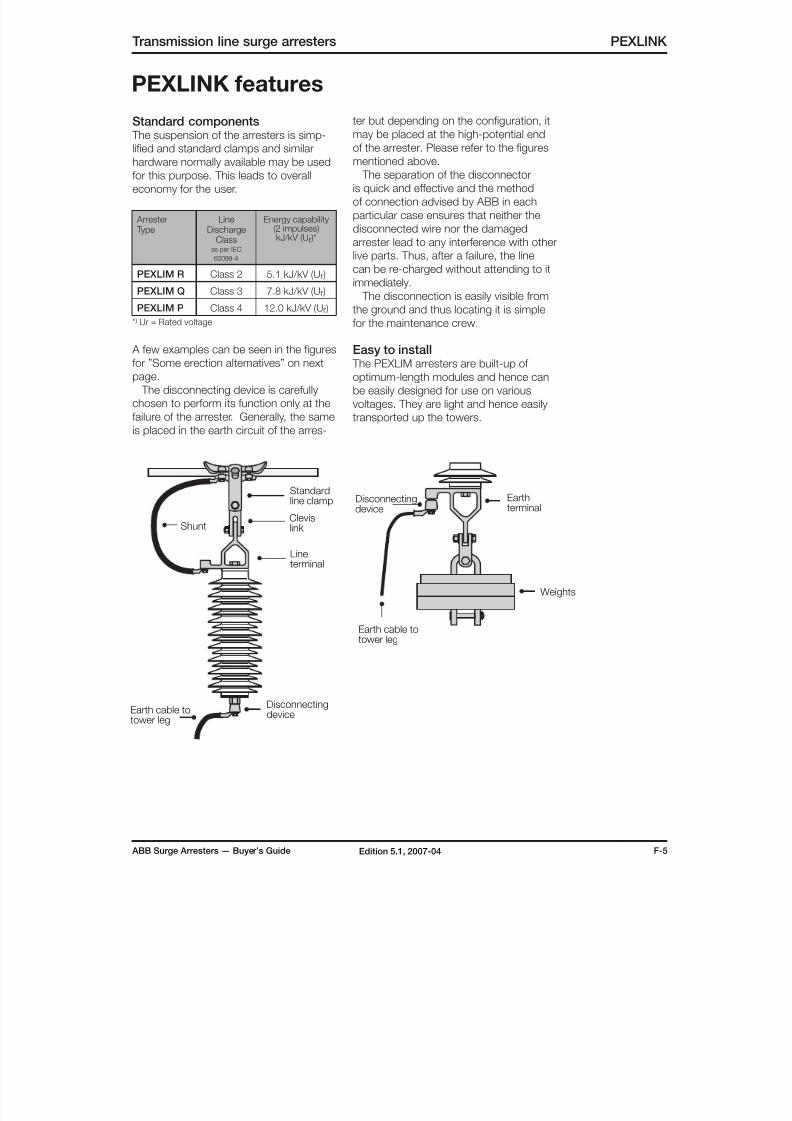
PEXLINK features
Standard components The suspension of the arresters is simp-
lified and standard clamps and similar
hardware normally available may be usedfor this purpose. This leads to overall
economy for the user.
Arrester Type
LineDischarge
Classas per IEC
60099-4
Energy capability(2 impulses)kJ/kV (Ur )*
PEXLIM R Class 2 5.1 kJ/kV (Ur )
PEXLIM Q Class 3 7.8 kJ/kV (Ur )
PEXLIM P Class 4 12.0 kJ/kV (Ur )
* ) Ur = Rated voltage
A few examples can be seen in the figures
for ”Some erection alternatives” on next
page.
The disconnecting device is carefully
chosen to perform its function only at the
failure of the arrester. Generally, the same
is placed in the earth circuit of the arres-
DisconnectingdeviceEarth cable to
tower leg
Standard
line clamp
Shunt
Disconnectingdevice
Earth cable totower leg
Weights
Clevislink
Lineterminal
Earthterminal
ter but depending on the configuration, it
may be placed at the high-potential end
of the arrester. Please refer to the figures
mentioned above. The separation of the disconnector
is quick and effective and the method
of connection advised by ABB in each
particular case ensures that neither the
disconnected wire nor the damaged
arrester lead to any interference with other
live parts. Thus, after a failure, the line
can be re-charged without attending to it
immediately.
The disconnection is easily visible from
the ground and thus locating it is simple
for the maintenance crew.
Easy to install The PEXLIM arresters are built-up of
optimum-length modules and hence can
be easily designed for use on various
voltages. They are light and hence easily
transported up the towers.
8/10/2019 ABB Extra High Voltage Surge Arresters Up to 420kV
http://slidepdf.com/reader/full/abb-extra-high-voltage-surge-arresters-up-to-420kv 26/96
F-6 ABB Surge Arresters — Buyer’s GuideEdition 5.1, 2007-04
PEXLINK Transmission line surge arresters
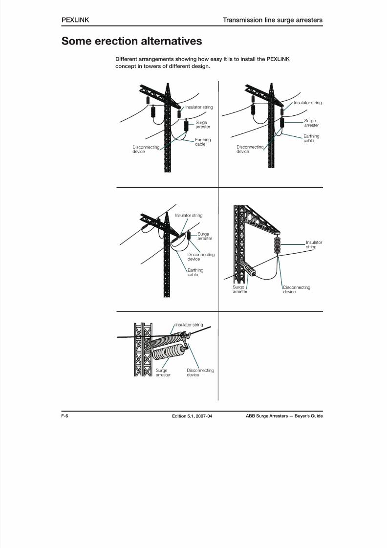
Some erection alternatives
Different arrangements showing how easy it is to install the PEXLINK
concept in towers of different design.
Insulator string
Surgearrester
Earthingcable
Disconnectingdevice
Insulator string
Surgearrester
Earthingcable
Disconnectingdevice
Insulatorstring
Surgearrester
Disconnectingdevice
Insulator string
Surgearrester
Earthingcable
Disconnectingdevice
Insulator string
Surgearrester
Disconnectingdevice

8/10/2019 ABB Extra High Voltage Surge Arresters Up to 420kV
http://slidepdf.com/reader/full/abb-extra-high-voltage-surge-arresters-up-to-420kv 27/96
ABB Surge Arresters — Buyer’s Guide G-1Edition 5.1, 2007-04
Quality control and testing
Quality control and testing
Type tests
Type (design) tests have been performedin accordance both with IEC 60099-4
and ANSI/IEEE C62.11. Test reports are
available on request.
Routine testsRoutine tests are performed on ZnO
blocks as well as on assembled arres-
ter units and accessories. The most
important type tests data is verified on
all batches of ZnO blocks, thus verifying
catalogue data.
Tests on ZnO blocksEnergy withstand test on all blocks
The blocks pass three energy test
cycles with cooling in-between. In
each cycle, the injected energy is far
in excess of the single impulse energy
capability. Blocks with insufficient energy
capability are automatically rejected.
Classification of all blocks
The blocks are classified at 1 mA (d.c.)
and 10 kA (8/20 µs) and the residual
voltages are printed on each blocktogether with a batch identification.
Finally all blocks are visually inspected.
Accelerated life tests on samples
Power losses after 1 000 hours cal-
culated from a test with shorter dura-
tion (approx. 300 hours) at an elevated
temperature of 115°C at 1.05 times Uc
shall not exceed the losses at start of
the test. Batches in which unapproved
blocks appear are rejected.
Impulse current tests on samples
Blocks are subjected to high current
impulses (4/10 µs) and long duration
current impulses (2 500 µs) of amplitu-
des verifying catalogue data.
Other sample tests
In addition to the above, low current
characteristics, protection characteris-
tics and capacitance are checked on
samples.
Tests on assembled
mechanical unitsRoutine tests on units fulfil the demands
of both IEC 60099-4 and ANSI/IEEE
C62.11. Each arrester unit has a serial
number as per IEC 60099-4
Guaranteed residual voltage
The residual voltage at 10 kA, 8/20 µs
impulse current of each unit is calculated
as the sum of the residual voltages for all
blocks connected in series in the unit.
The residual voltage of the complete
arrester is the sum of the residual voltages
for its units.
Tightness check (only for EXLIM and HS
PEXLIM arresters)
It is performed by placing each unit in a
vacuum chamber connected to a He-
spectrometer. Maximum permissible
leakage is 0.00001 mbarl/s at a pressure
difference of 0.1 MPa.
Power frequency reference voltage
Reference voltage is measured on each
arrester unit.
Internal corona
It is checked on each unit at 0.9 times Ur.
A steady internal corona level less than
5 pC is required in a pass/no-pass test.
Grading current
It is measured at Uc on each unit.
Power losses
They are measured at Uc on each unit
verifying that the thermal performance is incompliance with performed type tests.
Test reports
Routine test reports are filed and are available
on request. The reports include reference
voltages, power losses and residual voltages.
Tests on accessoriesSurge counters, EXCOUNT-A
All counters are routine-tested in a pass/
no-pass test before leaving the factory.
ABB is certified to fulfil the requirements of ISO 9001.
8/10/2019 ABB Extra High Voltage Surge Arresters Up to 420kV
http://slidepdf.com/reader/full/abb-extra-high-voltage-surge-arresters-up-to-420kv 28/96
H-1 ABB Surge Arresters — Buyer’s GuideEdition 5.1, 2007-04
PEXLIM R Silicone-housed arresters
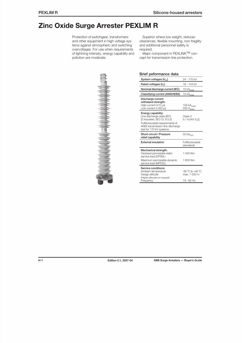
Zinc Oxide Surge Arrester PEXLIM R
Protection of switchgear, transformers
and other equipment in high voltage sys-
tems against atmospheric and switching
overvoltages. For use when requirementsof lightning intensity, energy capability and
pollution are moderate.
Superior where low weight, reduced
clearances, flexible mounting, non-fragility
and additional personnel safety is
required.Major component in PEXLINK TM con-
cept for transmission line protection.
Brief peformance data
System voltages (Um ) 24 - 170 kV
Rated voltages (Ur ) 18 - 144 kV
Nominal discharge current (IEC) 10 kA peak
Classifying current (ANSI/IEEE) 10 kA peak
Discharge current
withstand strength:High current 4/10 µsLow current 2 000 µs
100 kA peak 550 A peak
Energy capability:Line discharge class (IEC)[2 impulses, (IEC Cl. 8.5.5)
Fulfils/exceeds requirements of ANSI transmission-line dischargetest for 170 kV systems.
Class 25.1 kJ/kV (Ur )]
Short-circuit / Pressurerelief capability
50 kA sym
External insulation Fulfils/exceedsstandards
Mechanical strength:
Declared permissible staticservice load (DPSSL)
Maximum permissible dynamicservice load (MPDSL)
1 000 Nm
1 600 Nm
Service conditions: Ambient temperatureDesign altitude(Higher altitudes on request)
Frequency
-50 °C to +45 °Cmax. 1 000 m
15 - 62 Hz
8/10/2019 ABB Extra High Voltage Surge Arresters Up to 420kV
http://slidepdf.com/reader/full/abb-extra-high-voltage-surge-arresters-up-to-420kv 29/96
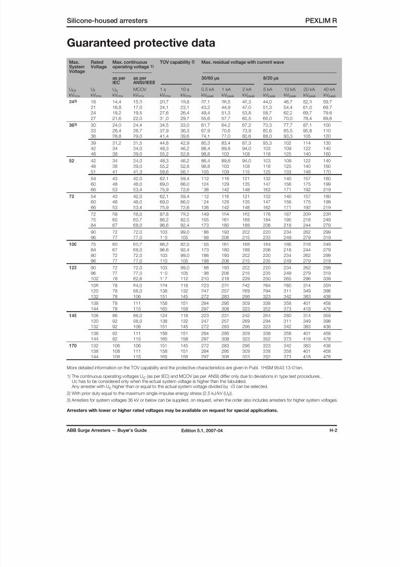
ABB Surge Arresters — Buyer’s Guide H-2Edition 5.1, 2007-04
Max.System
Voltage
Rated Voltage
Max. continuousoperating voltage 1)
TOV capability 2) Max. residual voltage with current wave
as per
IEC
as per
ANSI/IEEE
30/60 µs 8/20 µs
UmkV rms
UrkV rms
UckV rms
MCOV
kV rms
1 s
kV rms
10 s
kV rms
0.5 kA
kV peak
1 kA
kV peak
2 kA
kV peak
5 kA
kV peak
10 kA
kV peak
20 kA
kV peak
40 kA
kV peak
243) 18 14,4 15,3 20,7 19,8 37,1 38,5 40,3 44,0 46,7 52,3 59,7
21 16,8 17,0 24,1 23,1 43,2 44,9 47,0 51,3 54,4 61,0 69,7
24 19,2 19,5 27,6 26,4 49,4 51,3 53,8 58,7 62,2 69,7 79,6
27 21,6 22,0 31,0 29,7 55,6 57,7 60,5 66,0 70,0 78,4 89,6
363) 30 24,0 24,4 34,5 33,0 61,7 64,2 67,2 73,3 77,7 87,1 100
33 26,4 26,7 37,9 36,3 67,9 70,6 73,9 80,6 85,5 95,8 110
36 28,8 29,0 41,4 39,6 74,1 77,0 80,6 88,0 93,3 105 120
39 31,2 31,5 44,8 42,9 80,3 83,4 87,3 95,3 102 114 130
42 34 34,0 48,3 46,2 86,4 89,8 94,0 103 109 122 140
48 38 39,0 55,2 52,8 98,8 103 108 118 125 140 160
52 42 34 34,0 48,3 46,2 86,4 89,8 94,0 103 109 122 140
48 38 39,0 55,2 52,8 98,8 103 108 118 125 140 160
51 41 41,3 58,6 56,1 105 109 115 125 133 148 170
54 43 42,0 62,1 59,4 112 116 121 132 140 157 180
60 48 48,0 69,0 66,0 124 129 135 147 156 175 199
66 53 53,4 75,9 72,6 136 142 148 162 171 192 219
72 54 43 42,0 62,1 59,4 112 116 121 132 140 157 180
60 48 48,0 69,0 66,0 124 129 135 147 156 175 199
66 53 53,4 75,9 72,6 136 142 148 162 171 192 219
72 58 58,0 82,8 79,2 149 154 162 176 187 209 239
75 60 60,7 86,2 82,5 155 161 168 184 195 218 249
84 67 68,0 96,6 92,4 173 180 188 206 218 244 279
90 72 72,0 103 99,0 186 193 202 220 234 262 299
96 77 77,0 110 105 198 206 215 235 249 279 319
100 75 60 60,7 86,2 82,5 155 161 168 184 195 218 249
84 67 68,0 96.6 92,4 173 180 188 206 218 244 279
90 72 72,0 103 99,0 186 193 202 220 234 262 299
96 77 77,0 110 105 198 206 215 235 249 279 319
123 90 72 72,0 103 99,0 186 193 202 220 234 262 299
96 77 77,0 110 105 198 206 215 235 249 279 319
102 78 82,6 117 112 210 218 229 250 265 296 339
108 78 84,0 124 118 223 231 242 264 280 314 359
120 78 98,0 138 132 247 257 269 294 311 349 398
132 78 106 151 145 272 283 296 323 342 383 438
138 78 111 158 151 284 295 309 338 358 401 458
144 78 115 165 158 297 308 323 352 373 418 478
145 108 86 86,0 124 118 223 231 242 264 280 314 359
120 92 98,0 138 132 247 257 269 294 311 349 398
132 92 106 151 145 272 283 296 323 342 383 438
138 92 111 158 151 284 295 309 338 358 401 458
144 92 115 165 158 297 308 323 352 373 418 478
170 132 106 106 151 145 272 283 296 323 342 383 438
138 108 111 158 151 284 295 309 338 358 401 458
144 108 115 165 158 297 308 323 352 373 418 478
More detailed information on the TOV capability and the protective characteristics are given in Publ. 1HSM 9543 13-01en.
1) The continuous operating voltages Uc (as per IEC) and MCOV (as per ANSI) differ only due to deviations in type test procedures. Uc has to be considered only when the actual system voltage is higher than the tabulated. Any arrester with Uc higher than or equal to the actual system voltage divided by √3 can be selected.
2) With prior duty equal to the maximum single-impulse energy stress (2.5 kJ/kV (Ur )).
3) Arresters for system voltages 36 kV or below can be supplied, on request, when the order also includes arresters for higher system voltages.
Arresters with lower or higher rated voltages may be available on request for special applications.
Guaranteed protective data
Silicone-housed arresters PEXLIM R
8/10/2019 ABB Extra High Voltage Surge Arresters Up to 420kV
http://slidepdf.com/reader/full/abb-extra-high-voltage-surge-arresters-up-to-420kv 30/96
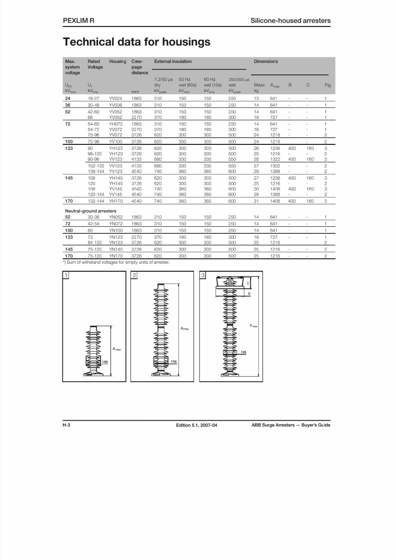
H-3 ABB Surge Arresters — Buyer’s GuideEdition 5.1, 2007-04
Max.
system
voltage
Rated
Voltage
Housing Cree-
page
distance
mm
External insulation Dimensions
UmkV rms
UrkV rms
1.2/50 µs
dry
kV peak
50 Hz
wet (60s)
kV rms
60 Hz
wet (10s)
kV rms
250/2500 µs
wet
kV peak
Mass
kg
A max B C Fig.
24 18-27 YV024 1863 310 150 150 250 13 641 - - 1
36 30-48 YV036 1863 310 150 150 250 14 641 - - 1
52 42-60 YV052 1863 310 150 150 250 14 641 - - 1
66 YV052 2270 370 180 180 300 16 727 - - 1
72 54-60 YH072 1863 310 150 150 250 14 641 - - 1
54-72 YV072 2270 370 180 180 300 16 727 - - 1
75-96 YV072 3726 620 300 300 500 24 1216 - - 2
100 75-96 YV100 3726 620 300 300 500 24 1216 - - 2
123 90 YH123 3726 620 300 300 500 26 1236 400 160 3
96-120 YH123 3726 620 300 300 500 25 1216 - - 2
90-96 YV123 4133 680 330 330 550 28 1322 400 160 3
102-132 YV123 4133 680 330 330 550 27 1302 - - 2138-144 YV123 4540 740 360 360 600 29 1388 - - 2
145 108 YH145 3726 620 300 300 500 27 1236 400 160 3
120 YH145 3726 620 300 300 500 25 1216 - - 2
108 YV145 4540 740 360 360 600 30 1408 400 160 3
120-144 YV145 4540 740 360 360 600 29 1388 - - 2
170 132-144 YH170 4540 740 360 360 600 31 1408 400 160 3
Neutral-ground arresters
52 30-36 YN052 1863 310 150 150 250 14 641 - - 1
72 42-54 YN072 1863 310 150 150 250 14 641 - - 1
100 60 YN100 1863 310 150 150 250 14 641 - - 1
123 72 YN123 2270 370 180 180 300 16 727 - - 1
84-120 YN123 3726 620 300 300 500 25 1216 - - 2
145 75-120 YN145 3726 620 300 300 500 25 1216 - - 2170 75-120 YN170 3726 620 300 300 500 25 1216 - - 2
*) Sum of withstand voltages for empty units of arrester.
PEXLIM R Silicone-housed arresters
Technical data for housings
1 2 3
8/10/2019 ABB Extra High Voltage Surge Arresters Up to 420kV
http://slidepdf.com/reader/full/abb-extra-high-voltage-surge-arresters-up-to-420kv 31/96
ABB Surge Arresters — Buyer’s Guide H-4Edition 5.1, 2007-04
Silicone-housed arresters PEXLIM R
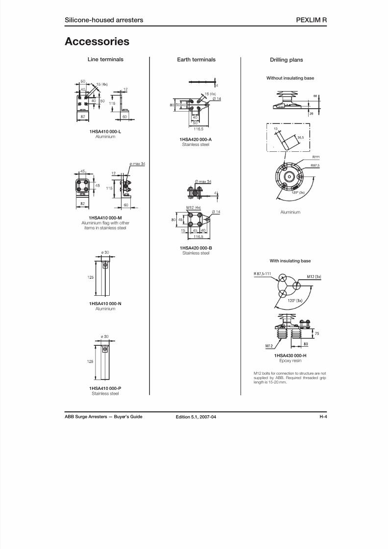
Accessories
1HSA410 000-L Aluminium
1HSA410 000-M Aluminium flag with other
items in stainless steel
1HSA410 000-N Aluminium
1HSA420 000-A Stainless steel
1HSA420 000-BStainless steel
1HSA430 000-HEpoxy resin
With insulating base
Without insulating base
1HSA410 000-PStainless steel
Line terminals Earth terminals
M12 bolts for connection to structure are notsupplied by ABB. Required threaded griplength is 15-20 mm.
Drilling plans
Aluminium
8/10/2019 ABB Extra High Voltage Surge Arresters Up to 420kV
http://slidepdf.com/reader/full/abb-extra-high-voltage-surge-arresters-up-to-420kv 32/96
H-5 ABB Surge Arresters — Buyer’s GuideEdition 5.1, 2007-04
PEXLIM R Silicone-housed arresters
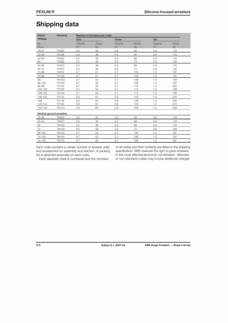
Shipping data
Rated
Voltage
Housing Number of arresters per crate
One Three Six
Ur
kV rms
Volume
m3
Gross
kg
Volume
m3
Gross
kg
Volume
m3
Gross
kg18-27 YV024 0.5 35 0.5 65 0.9 110
30-48 YV036 0.5 36 0.5 68 0.9 116
42-60 YV052 0.5 36 0.5 68 0.9 116
66 YV052 0.5 38 0.5 74 0.9 128
54-60 YH072 0.5 36 0.5 68 0.9 116
54-72 YV072 0.5 38 0.5 74 0.9 128
75-96 YV072 0.7 51 0.7 103 1.2 181
75-96 YV100 0.7 51 0.7 103 1.2 181
90 YH123 0.7 53 0.7 109 1.2 193
96-120 YH123 0.7 52 0.7 106 1.2 187
90-96 YV123 0.7 55 0.7 115 1.2 205
102-132 YV123 0.7 54 0.7 112 1.2 199
108-120 YH145 0.7 54 0.7 112 1.2 199
138-144 YV123 0.9 61 0.9 123 1.5 216
108 YV145 0.9 62 0.9 126 1.5 222
120-144 YV145 0.9 61 0.9 123 1.5 216
132-144 YH170 0.9 63 0.9 129 1.5 228
Neutral-ground arresters
30-36 YN052 0.5 36 0.5 68 0.9 116
42-54 YN072 0.5 36 0.5 68 0.9 116
60 YN100 0.5 36 0.5 68 0.9 116
72 YN123 0.5 38 0.5 74 0.9 128
84-120 YN123 0.7 52 0.7 106 1.2 187
75-120 YN145 0.7 52 0.7 106 1.2 187
75-120 YN170 0.7 52 0.7 106 1.2 187
Each crate contains a certain number of arrester units
and accessories for assembly and erection. A packing
list is attached externally on each crate.
Each separate crate is numbered and the numbers
of all crates and their contents are listed in the shipping
specification. ABB reserves the right to pack arresters
in the most effective/economic combination. Alternate
or non-standard crates may involve additional charges.
8/10/2019 ABB Extra High Voltage Surge Arresters Up to 420kV
http://slidepdf.com/reader/full/abb-extra-high-voltage-surge-arresters-up-to-420kv 33/96
ABB Surge Arresters — Buyer’s Guide I-1Edition 5.1, 2007-04
Silicone-housed arresters PEXLIM Q
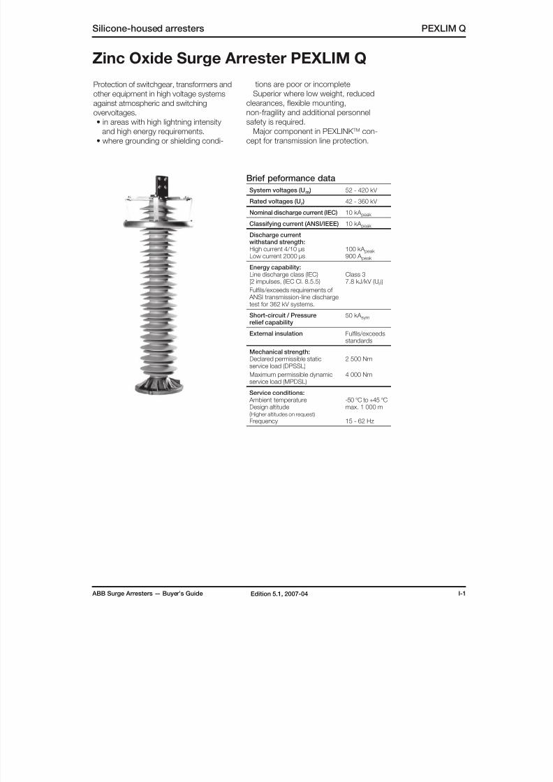
Zinc Oxide Surge Arrester PEXLIM Q
Protection of switchgear, transformers and
other equipment in high voltage systems
against atmospheric and switching
overvoltages.• in areas with high lightning intensity
and high energy requirements.
• where grounding or shielding condi-
tions are poor or incomplete
Superior where low weight, reduced
clearances, flexible mounting,
non-fragility and additional personnelsafety is required.
Major component in PEXLINK TM con-
cept for transmission line protection.
Brief peformance data
System voltages (Um ) 52 - 420 kV
Rated voltages (Ur ) 42 - 360 kV
Nominal discharge current (IEC) 10 kA peak
Classifying current (ANSI/IEEE) 10 kA peak
Discharge currentwithstand strength:High current 4/10 µsLow current 2000 µs
100 kA peak 900 A peak
Energy capability:Line discharge class (IEC)[2 impulses, (IEC Cl. 8.5.5)
Fulfils/exceeds requirements of ANSI transmission-line dischargetest for 362 kV systems.
Class 37.8 kJ/kV (Ur )]
Short-circuit / Pressurerelief capability
50 kA sym
External insulation Fulfils/exceedsstandards
Mechanical strength:Declared permissible staticservice load (DPSSL)
Maximum permissible dynamicservice load (MPDSL)
2 500 Nm
4 000 Nm
Service conditions: Ambient temperatureDesign altitude(Higher altitudes on request)
Frequency
-50 °C to +45 °Cmax. 1 000 m
15 - 62 Hz
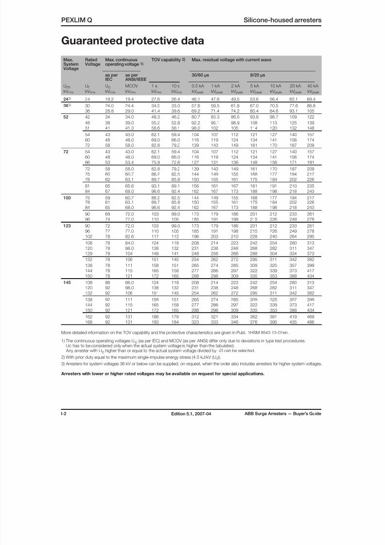
8/10/2019 ABB Extra High Voltage Surge Arresters Up to 420kV
http://slidepdf.com/reader/full/abb-extra-high-voltage-surge-arresters-up-to-420kv 34/96

8/10/2019 ABB Extra High Voltage Surge Arresters Up to 420kV
http://slidepdf.com/reader/full/abb-extra-high-voltage-surge-arresters-up-to-420kv 35/96
ABB Surge Arresters — Buyer’s Guide I-3Edition 5.1, 2007-04
Max. Rated Voltage
Max. continuousoperating voltage 1)
TOV capability 2) Max. residual voltage with current wave
as per
IEC
as per
ANSI/IEEE
30/60 µs 8/20 µs
UmkV rms
UrkV rms
UckV rms
MCOV
kV rms
1 s
kV rms
10 s
kV rms
0.5 kA
kV peak
1 kA
kV peak
2 kA
kV peak
5 kA
kV peak
10 kA
kV peak
20 kA
kV peak
40 kA
kV peak
170 132 106 106 151 145 254 262 272 295 311 342 382
144 108 115 165 158 277 286 297 322 339 373 417
150 108 121 172 165 288 298 309 335 353 388 434
162 108 131 186 178 312 321 334 362 381 419 469
168 108 131 193 184 323 333 346 376 395 435 486
192 108 152 220 211 369 381 396 429 452 497 555
245 180 144 144 207 198 346 357 371 402 423 466 521
192 154 154 220 211 369 381 396 429 452 497 555
198 156 160 227 217 381 393 408 443 466 512 573
210 156 170 241 231 404 417 433 469 494 543 608
216 156 175 248 237 415 428 445 483 508 559 625
219 156 177 251 240 421 434 451 489 515 567 634
222 156 179 255 244 427 440 458 496 522 574 642
228 156 180 262 250 438 452 470 510 536 590 660
300 216 173 175 248 237 415 428 445 483 508 559 625240 191 191 276 264 461 476 495 536 564 621 694
258 191 209 296 283 496 512 532 576 607 667 746
264 191 212 303 290 507 523 544 590 621 683 764
276 191 220 317 303 530 547 569 617 649 714 798
362 258 206 209 296 283 496 512 532 576 607 667 746
264 211 212 303 290 507 523 544 590 621 683 764
276 221 221 317 303 530 547 569 617 649 714 798
288 230 230 331 316 553 571 593 643 677 745 833
420 330 264 267 379 363 634 654 680 737 776 854 954
336 267 272 386 369 646 666 692 751 790 869 972
342 267 277 393 376 657 678 705 764 804 885 989
360 267 291 414 396 692 714 742 804 846 931 1046
More detailed information on the TOV capability and the protective characteristics are given in Publ. 1HSM 9543 13-01en.
1) The continuous operating voltages Uc (as per IEC) and MCOV (as per ANSI) differ only due to deviations in type test procedures. Uc has to be considered only when the actual system voltage is higher than the tabulated. Any arrester with Uc higher than or equal to the actual system voltage divided by √3 can be selected.
2) With prior duty equal to the maximum single-impulse energy stress (4.5 kJ/kV (Ur )).
3) Arresters for system voltages 36 kV or below can be supplied, on request, when the order also includes arresters for higher system voltages.
Arresters with lower or higher rated voltages may be available on request for special applications.
Guaranteed protective data
Silicone-housed arresters PEXLIM Q
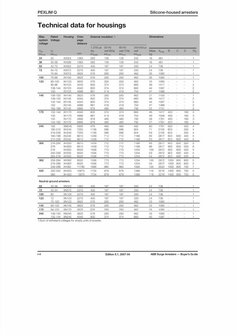
8/10/2019 ABB Extra High Voltage Surge Arresters Up to 420kV
http://slidepdf.com/reader/full/abb-extra-high-voltage-surge-arresters-up-to-420kv 36/96
I-4 ABB Surge Arresters — Buyer’s GuideEdition 5.1, 2007-04
PEXLIM Q Silicone-housed arresters
Max.
system
voltage
Rated
Voltage
Housing Cree-
page
distance
mm
External insulation *) Dimensions
UmkV rms
UrkV rms
1.2/50 µs
dry
kV peak
50 Hz
wet (60s)
kV rms
60 Hz
wet (10s)
kV rms
250/2500 µs
wet
kV peak
Mass
kg
A max B C D Fig.
24 24 XV024 1363 283 126 126 242 16 481 - - - 1
36 30-36 XV036 1363 283 126 126 242 16 481 - - - 1
52 42-72 XV052 2270 400 187 187 330 24 736 - - - 1
72 54-72 XV072 2270 400 187 187 330 24 736 - - - 1
75-84 XV072 3625 578 293 293 462 35 1080 - - - 1
100 75-96 XV100 3625 578 293 293 462 35 1080 - - - 1
123 90-120 XH123 3625 578 293 293 462 35 1080 - - - 1
90-96 XV123 4540 800 374 374 660 46 1417 - - - 2
108-144 XV123 4540 800 374 374 660 44 1397 - - - 2
150 XV123 4988 861 419 419 704 47 1486 - - - 2
145 108-120 XH145 3625 578 293 293 462 37 1100 - - - 1
108-120 XV145 4540 800 374 374 660 46 1417 - - - 2132-144 XV145 4540 800 374 374 660 44 1397 - - - 2
150 XV145 4988 861 419 419 704 47 1486 - - - 2
162-168 XV145 5895 978 480 480 792 55 1741 - - - 2
170 132-144 XH170 4540 800 374 374 660 46 1417 400 - 160 3
150 XH170 4988 861 419 419 704 49 1506 400 - 160 3
132 XV170 5895 978 480 480 792 58 1761 400 - 160 3
144-192 XV170 5895 978 480 480 792 57 1761 400 - 160 3
245 192 XM245 5895 978 480 480 492 60 1761 600 - 300 4
180-210 XH245 7250 1156 586 586 924 71 2105 600 - 300 4
216-228 XH245 7250 1156 586 586 924 69 2105 600 - 300 4
180-198 XV245 8613 1439 712 712 1166 86 2617 800 600 400 5
210-228 XV245 8613 1439 712 712 1166 83 2617 800 600 400 5
300 216-264 XH300 8613 1439 712 712 1166 86 2617 900 600 500 5
276 XH300 8613 1439 712 712 1166 86 2617 900 600 500 6
216 XV300 9520 1556 773 773 1254 100 2872 900 600 500 5240-258 XV300 9520 1556 773 773 1254 99 2872 900 600 500 5
264-276 XV300 9520 1556 773 773 1254 94 2872 900 600 500 5
362 258-264 XH362 9520 1556 773 773 1254 100 2872 1200 800 600 5
276-288 XH362 9520 1556 773 773 1254 99 2872 1200 800 600 5
258-288 XV362 11790 1956 960 960 1584 125 3533 1400 800 700 7
420 330-342 XH420 10875 1734 879 879 1386 116 3216 1400 800 700 5
360 XH420 10875 1734 879 879 1386 116 3216 1400 800 700 5
Neutral-ground arresters
52 30-36 XN052 1363 400 187 187 330 24 736 - - 1
72 42-54 XN072 2270 400 187 187 330 24 736 - - 1
100 60 XN100 2270 400 187 187 330 24 736 - - 1
123 72 XN123 2270 400 187 187 330 24 736 - - 175-120 XN123 3625 578 293 293 462 35 1080 - - 1
145 84-120 XN145 3625 578 293 293 462 35 1080 - - - 1
170 84-120 XN170 3625 578 293 293 462 36 1080 - - - 1
245 108-120 XN245 3625 578 293 293 462 36 1080 - - - 1
132-144 XN245 4540 800 374 374 660 45 1397 - - - 1
*) Sum of withstand voltages for empty units of arrester.
Technical data for housings

8/10/2019 ABB Extra High Voltage Surge Arresters Up to 420kV
http://slidepdf.com/reader/full/abb-extra-high-voltage-surge-arresters-up-to-420kv 37/96
ABB Surge Arresters — Buyer’s Guide I-5Edition 5.1, 2007-04
Silicone-housed arresters PEXLIM Q
Technical data for housings
7
1 32 4
5 6
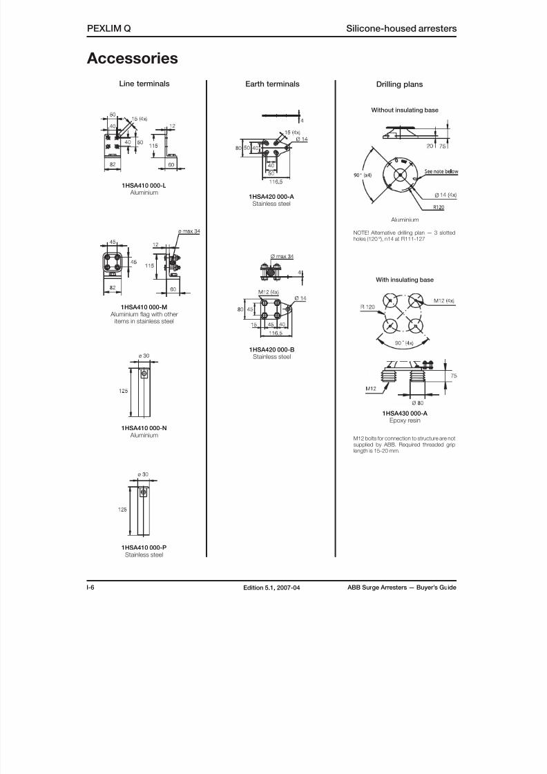
8/10/2019 ABB Extra High Voltage Surge Arresters Up to 420kV
http://slidepdf.com/reader/full/abb-extra-high-voltage-surge-arresters-up-to-420kv 38/96
I-6 ABB Surge Arresters — Buyer’s GuideEdition 5.1, 2007-04
PEXLIM Q Silicone-housed arresters
Accessories
1HSA410 000-L Aluminium
1HSA410 000-M Aluminium flag with other
items in stainless steel
1HSA410 000-N Aluminium
1HSA420 000-A Stainless steel
1HSA420 000-BStainless steel
1HSA430 000-A Epoxy resin
With insulating base
Without insulating base
1HSA410 000-PStainless steel
Line terminals Earth terminals
M12 bolts for connection to structure are notsupplied by ABB. Required threaded griplength is 15-20 mm.
Drilling plans
NOTE! Alternative drilling plan — 3 slottedholes (120 º), n14 at R111-127
Aluminium
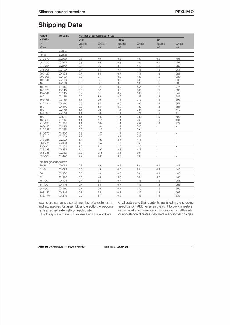
8/10/2019 ABB Extra High Voltage Surge Arresters Up to 420kV
http://slidepdf.com/reader/full/abb-extra-high-voltage-surge-arresters-up-to-420kv 39/96
ABB Surge Arresters — Buyer’s Guide I-7Edition 5.1, 2007-04
Silicone-housed arresters PEXLIM Q
Shipping Data
Rated
Voltage
Housing Number of arresters per crate
One Three Six
Ur
kV rms
Volume
m3
Gross
kg
Volume
m3
Gross
kg
Volume
m3
Gross
kg24 XV024
30-36 XV036
042-072 XV052 0.5 49 0.5 107 0.9 194
054-072 XV072 0.5 49 0.5 107 0.9 194
075-084 XV072 0.7 65 0.7 145 1.2 265
075-096 XV100 0.7 65 0.7 145 1.2 265
090-120 XH123 0.7 65 0.7 145 1.2 265
090-096 XV123 0.9 81 0.9 183 1.5 336
108-144 XV123 0.9 81 0.9 183 1.5 336
150 XV123 0.9 81 0.9 183 1.5 336
108-120 XH145 0.7 67 0.7 151 1.2 277
108-120 XV145 0.9 82 0.9 186 1.5 338
132-144 XV145 0.9 81 0.9 186 1.5 342
150 XV145 0.9 82 0.9 186 1.5 342162-168 XV145 1.1 95 1.1 215 1.9 395
132-144 XH170 0.9 84 0.9 192 1.5 354
150 XH170 0.9 84 0.9 192 1.5 354
132 XV170 1.1 98 1.1 224 1.9 413
144-192 XV170 1.1 98 1.1 224 1.9 413
192 XM245 1.1 100 1.1 230 1.9 425
180-210 XH245 1.1 111 1.1 263 1.9 491
216-228 XH245 1.1 109 1.1 257 1.9 479
180-198 XV245 1.0 164 1.7 340 - -
210-228 XV245 0.9 115 1.5 291 - -
216-276 XH300 0.9 126 1.7 345 - -
216 XV300 1.5 211 2.6 443 - -
240-258 XV300 1.4 192 2.3 416 - -
264-276 XV300 1.0 157 1.7 369 - -
258-264 XH362 1.5 211 2.5 443 - -
276-288 XH362 1.4 192 2.3 416 - -
258-288 XV362 2.2 278 3.8 564 - -
330-360 XH420 2.2 268 3.8 534 - -
Neutral-ground arresters
30-36 XN052 0.5 49 0.5 83 0.9 146
42-54 XN072 0.5 49 0.5 83 0.9 146
60 XN100 0.5 49 0.5 83 0.9 146
72 XN123 0.5 49 0.5 83 0.9 146
75-120 XN123 0.7 65 0.7 145 1.2 265
84-120 XN145 0.7 65 0.7 145 1.2 265
84-120 XN170 0.7 65 0.7 145 1.2 265
108-120 XN245 0.7 65 0.7 145 1.2 265132, 144 XN245 0.9 81 0.9 183 1.5 336
Each crate contains a certain number of arrester units
and accessories for assembly and erection. A packing
list is attached externally on each crate.
Each separate crate is numbered and the numbers
of all crates and their contents are listed in the shipping
specification. ABB reserves the right to pack arresters
in the most effective/economic combination. Alternate
or non-standard crates may involve additional charges.
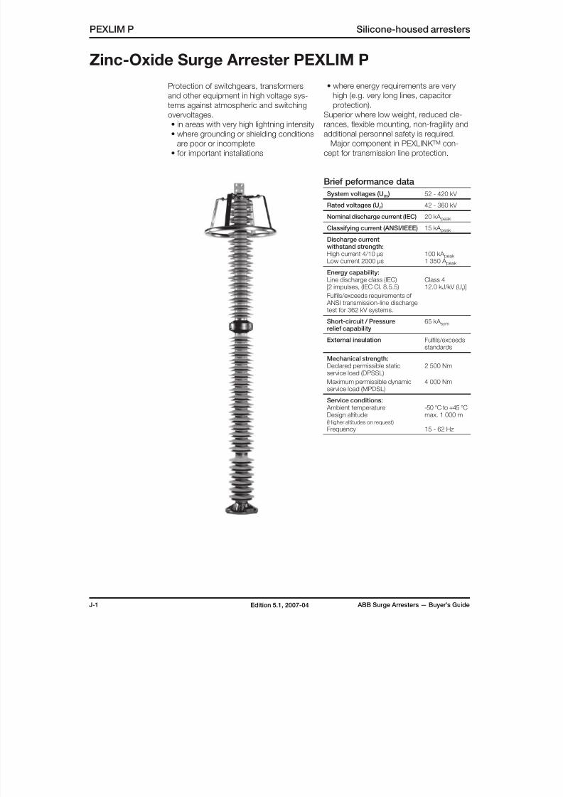
8/10/2019 ABB Extra High Voltage Surge Arresters Up to 420kV
http://slidepdf.com/reader/full/abb-extra-high-voltage-surge-arresters-up-to-420kv 40/96
J-1 ABB Surge Arresters — Buyer’s GuideEdition 5.1, 2007-04
Zinc-Oxide Surge Arrester PEXLIM P
PEXLIM P Silicone-housed arresters
Protection of switchgears, transformers
and other equipment in high voltage sys-
tems against atmospheric and switching
overvoltages.• in areas with very high lightning intensity
• where grounding or shielding conditions
are poor or incomplete
• for important installations
• where energy requirements are very
high (e.g. very long lines, capacitor
protection).
Superior where low weight, reduced cle-rances, flexible mounting, non-fragility and
additional personnel safety is required.
Major component in PEXLINK TM con-
cept for transmission line protection.
Brief peformance data
System voltages (Um ) 52 - 420 kV
Rated voltages (Ur ) 42 - 360 kV
Nominal discharge current (IEC) 20 kA peak
Classifying current (ANSI/IEEE) 15 kA peak
Discharge currentwithstand strength:High current 4/10 µsLow current 2000 µs
100 kA peak 1 350 A peak
Energy capability:Line discharge class (IEC)[2 impulses, (IEC Cl. 8.5.5)
Fulfils/exceeds requirements of ANSI transmission-line dischargetest for 362 kV systems.
Class 412.0 kJ/kV (Ur )]
Short-circuit / Pressurerelief capability
65 kA sym
External insulation Fulfils/exceedsstandards
Mechanical strength:Declared permissible staticservice load (DPSSL)
Maximum permissible dynamicservice load (MPDSL)
2 500 Nm
4 000 Nm
Service conditions: Ambient temperatureDesign altitude(Higher altitudes on request)
Frequency
-50 °C to +45 °Cmax. 1 000 m
15 - 62 Hz
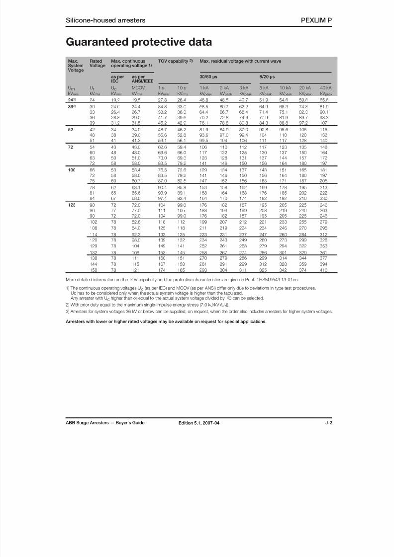
8/10/2019 ABB Extra High Voltage Surge Arresters Up to 420kV
http://slidepdf.com/reader/full/abb-extra-high-voltage-surge-arresters-up-to-420kv 41/96
ABB Surge Arresters — Buyer’s Guide J-2Edition 5.1, 2007-04
Silicone-housed arresters PEXLIM P
Guaranteed protective data
Max.System
Voltage
Rated Voltage
Max. continuousoperating voltage 1)
TOV capability 2) Max. residual voltage with current wave
as per
IEC
as per
ANSI/IEEE
30/60 µs 8/20 µs
UmkV rms
UrkV rms
UckV rms
MCOV
kV rms
1 s
kV rms
10 s
kV rms
1 kA
kV peak
2 kA
kV peak
3 kA
kV peak
5 kA
kV peak
10 kA
kV peak
20 kA
kV peak
40 kA
kV peak
243) 24 19.2 19.5 27.8 26.4 46.8 48.5 49.7 51.9 54.6 59.8 65.6
363) 30 24.0 24.4 34.8 33.0 58.5 60.7 62.2 64.9 68.3 74.8 81.9
33 26.4 26.7 38.2 36.3 64.4 66.7 68.4 71.4 75.1 82.3 90.1
36 28.8 29.0 41.7 39.6 70.2 72.8 74.6 77.9 81.9 89.7 98.3
39 31.2 31.5 45.2 42.9 76.1 78.8 80.8 84.3 88.8 97.2 107
52 42 34 34.0 48.7 46.2 81.9 84.9 87.0 90.8 95.6 105 115
48 38 39.0 55.6 52.8 93.6 97.0 99.4 104 110 120 132
51 41 41.3 59.1 56.1 99.5 104 106 111 117 128 140
72 54 43 43.0 62.6 59.4 106 110 112 117 123 135 148
60 48 48.0 69.6 66.0 117 122 125 130 137 150 164
63 50 51.0 73.0 69.3 123 128 131 137 144 157 172
72 58 58.0 83.5 79.2 141 146 150 156 164 180 197
100 66 53 53.4 76.5 72.6 129 134 137 143 151 165 181
72 58 58.0 83.5 79.2 141 146 150 156 164 180 197
75 60 60.7 87.0 82.5 147 152 156 163 171 187 205
78 62 63.1 90.4 85.8 153 158 162 169 178 195 213
81 65 65.6 93.9 89.1 158 164 168 176 185 202 222
84 67 68.0 97.4 92.4 164 170 174 182 192 210 230
123 90 72 72.0 104 99.0 176 182 187 195 205 225 246
96 77 77.0 111 105 188 194 199 208 219 240 263
90 72 72.0 104 99.0 176 182 187 195 205 225 246
102 78 82.6 118 112 199 207 212 221 233 255 279
108 78 84.0 125 118 211 219 224 234 246 270 295
114 78 92.3 132 125 223 231 237 247 260 284 312
120 78 98.0 139 132 234 243 249 260 273 299 328
129 78 104 149 141 252 261 268 279 294 322 353
132 78 106 153 145 258 267 274 286 301 329 361
138 78 111 160 151 270 279 286 299 314 344 377
144 78 115 167 158 281 291 299 312 328 359 394
150 78 121 174 165 293 304 311 325 342 374 410
More detailed information on the TOV capability and the protective characteristics are given in Publ. 1HSM 9543 13-01en.
1) The continuous operating voltages Uc (as per IEC) and MCOV (as per ANSI) differ only due to deviations in type test procedures. Uc has to be considered only when the actual system voltage is higher than the tabulated. Any arrester with Uc higher than or equal to the actual system voltage divided by √3 can be selected.
2) With prior duty equal to the maximum single-impulse energy stress (7.0 kJ/kV (Ur )).
3) Arresters for system voltages 36 kV or below can be supplied, on request, when the order also includes arresters for higher system voltages.
Arresters with lower or higher rated voltages may be available on request for special applications.

8/10/2019 ABB Extra High Voltage Surge Arresters Up to 420kV
http://slidepdf.com/reader/full/abb-extra-high-voltage-surge-arresters-up-to-420kv 42/96
J-3 ABB Surge Arresters — Buyer’s GuideEdition 5.1, 2007-04
PEXLIM P Silicone-housed arresters
Guaranteed protective data
Max.System
Voltage
Rated Voltage
Max. continuousoperating voltage 1)
TOV capability 2) Max. residual voltage with current wave
as per
IEC
as per
ANSI/IEEE
30/60 µs 8/20 µs
UmkV rms
UrkV rms
UckV rms
MCOV
kV rms
1 s
kV rms
10 s
kV rms
1 kA
kV peak
2 kA
kV peak
3 kA
kV peak
5 kA
kV peak
10 kA
kV peak
20 kA
kV peak
40 kA
kV peak
145 108 86 86.0 125 118 211 219 224 234 246 270 295
120 92 98.0 139 132 234 243 249 260 273 299 328
132 92 106 153 145 258 267 274 286 301 329 361
138 92 111 160 151 270 279 286 299 314 344 377
144 92 115 167 158 281 291 299 312 328 359 394
150 92 121 174 165 293 304 311 325 342 374 410
162 92 131 187 178 316 328 336 351 369 404 443
168 92 131 194 184 328 340 348 364 383 419 459
170 132 106 106 153 145 258 267 274 286 301 329 361
144 108 115 167 158 281 291 299 312 328 359 394
150 108 121 174 165 293 304 311 325 342 374 410
162 108 131 187 178 316 328 336 351 369 404 443168 108 131 194 184 328 340 348 364 383 419 459
180 108 144 208 198 351 364 373 390 410 449 492
192 108 152 222 211 375 388 398 415 437 479 525
245 180 144 144 208 198 351 364 373 390 410 449 492
192 154 154 222 211 375 388 398 415 437 479 525
198 156 160 229 217 387 400 410 428 451 494 541
210 156 170 243 231 410 425 435 454 478 524 574
214 156 173 248 235 419 434 445 464 488 535 586
216 156 175 250 237 422 437 448 467 492 539 590
219 156 177 254 240 427 443 454 474 499 546 598
222 156 179 257 244 433 449 460 480 506 554 607
228 156 180 264 250 445 461 473 493 519 568 623
300 216 173 175 250 237 422 437 448 467 492 539 590
228 182 182 264 250 445 461 473 493 519 568 623
240 191 191 278 264 468 485 497 519 546 598 656
258 191 209 299 283 504 522 535 558 587 643 705
264 191 212 306 290 515 534 547 571 601 658 721
276 191 220 320 303 539 558 572 597 628 688 754
362 258 206 209 299 283 504 522 535 558 587 643 705
264 211 212 306 290 515 534 547 571 601 658 721
276 221 221 320 303 539 558 572 597 628 688 754
288 230 230 334 316 562 582 597 623 656 718 787
420 330 264 267 382 363 644 667 684 714 751 823 901
336 267 272 389 369 656 679 696 727 765 838 918
342 267 277 396 376 667 691 709 740 779 852 934
360 267 291 417 396 702 728 746 779 819 897 983
More detailed information on the TOV capability and the protective characteristics are given in Publ. 1HSM 9543 13-01en.
1) The continuous operating voltages Uc (as per IEC) and MCOV (as per ANSI) differ only due to deviations in type test procedures. Uc has to be considered only when the actual system voltage is higher than the tabulated. Any arrester with Uc higher than or equal to the actual system voltage divided by √3 can be selected.
2) With prior duty equal to the maximum single-impulse energy stress (7.0 kJ/kV (Ur )).
Arresters with lower or higher rated voltages may be available on request for special applications.
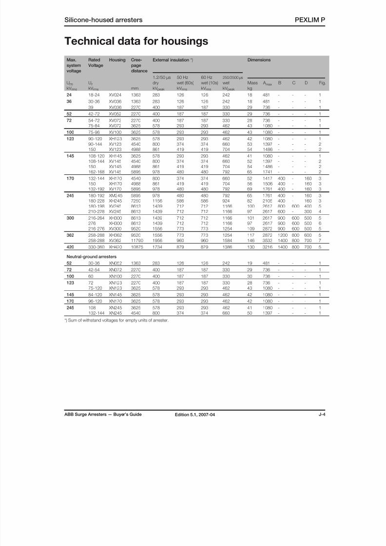
8/10/2019 ABB Extra High Voltage Surge Arresters Up to 420kV
http://slidepdf.com/reader/full/abb-extra-high-voltage-surge-arresters-up-to-420kv 43/96
ABB Surge Arresters — Buyer’s Guide J-4Edition 5.1, 2007-04
Silicone-housed arresters PEXLIM P
Technical data for housings
Max.
system
voltage
Rated
Voltage
Housing Cree-
page
distance
mm
External insulation *) Dimensions
UmkV rms
UrkV rms
1.2/50 µs
dry
kV peak
50 Hz
wet (60s)
kV rms
60 Hz
wet (10s)
kV rms
250/2500 µs
wet
kV peak
Mass
kg
A max B C D Fig.
24 18-24 XV024 1363 283 126 126 242 18 481 - - - 1
36 30-36 XV036 1363 283 126 126 242 18 481 - - - 1
39 XV036 2270 400 187 187 330 29 736 - - - 1
52 42-72 XV052 2270 400 187 187 330 29 736 - - - 1
72 54-72 XV072 2270 400 187 187 330 28 736 - - - 1
75-84 XV072 3625 578 293 293 462 43 1080 - - - 1
100 75-96 XV100 3625 578 293 293 462 43 1080 - - - 1
123 90-120 XH123 3625 578 293 293 462 42 1080 - - - 1
90-144 XV123 4540 800 374 374 660 53 1397 - - - 2
150 XV123 4988 861 419 419 704 54 1486 - - - 2
145 108-120 XH145 3625 578 293 293 462 41 1080 - - - 1
108-144 XV145 4540 800 374 374 660 52 1397 - - - 2150 XV145 4988 861 419 419 704 54 1486 - - - 2
162-168 XV145 5895 978 480 480 792 65 1741 - - - 2
170 132-144 XH170 4540 800 374 374 660 52 1417 400 - 160 3
150 XH170 4988 861 419 419 704 56 1506 400 - 160 3
132-192 XV170 5895 978 480 480 792 69 1761 400 - 160 3
245 180-192 XM245 5895 978 480 480 792 65 1761 400 - 160 3
180-228 XH245 7250 1156 586 586 924 82 2105 400 - 160 3
180-198 XV245 8613 1439 712 712 1166 100 2617 800 600 400 5
210-228 XV245 8613 1439 712 712 1166 97 2617 600 - 300 4
300 216-264 XH300 8613 1439 712 712 1166 101 2617 900 600 500 5
276 XH300 8613 1439 712 712 1166 97 2617 900 600 500 6
216-276 XV300 9520 1556 773 773 1254 109 2872 900 600 500 5
362 258-288 XH362 9520 1556 773 773 1254 117 2872 1200 800 600 5
258-288 XV362 11790 1956 960 960 1584 146 3533 1400 800 700 7
420 330-360 XH420 10875 1734 879 879 1386 130 3216 1400 800 700 5
Neutral-ground arresters
52 30-36 XN052 1363 283 126 126 242 19 481 - - - 1
72 42-54 XN072 2270 400 187 187 330 29 736 - - - 1
100 60 XN100 2270 400 187 187 330 30 736 - - - 1
123 72 XN123 2270 400 187 187 330 28 736 - - - 1
75-120 XN123 3625 578 293 293 462 43 1080 - - - 1
145 84-120 XN145 3625 578 293 293 462 42 1080 - - - 1
170 96-120 XN170 3625 578 293 293 462 42 1080 - - - 1
245 108 XN245 3625 578 293 293 462 41 1080 - - - 1
132-144 XN245 4540 800 374 374 660 50 1397 - - - 1
*) Sum of withstand voltages for empty units of arrester.

8/10/2019 ABB Extra High Voltage Surge Arresters Up to 420kV
http://slidepdf.com/reader/full/abb-extra-high-voltage-surge-arresters-up-to-420kv 44/96
J-5 ABB Surge Arresters — Buyer’s GuideEdition 5.1, 2007-04
1
PEXLIM P Silicone-housed arresters
32 4
Technical data for housings
5 76
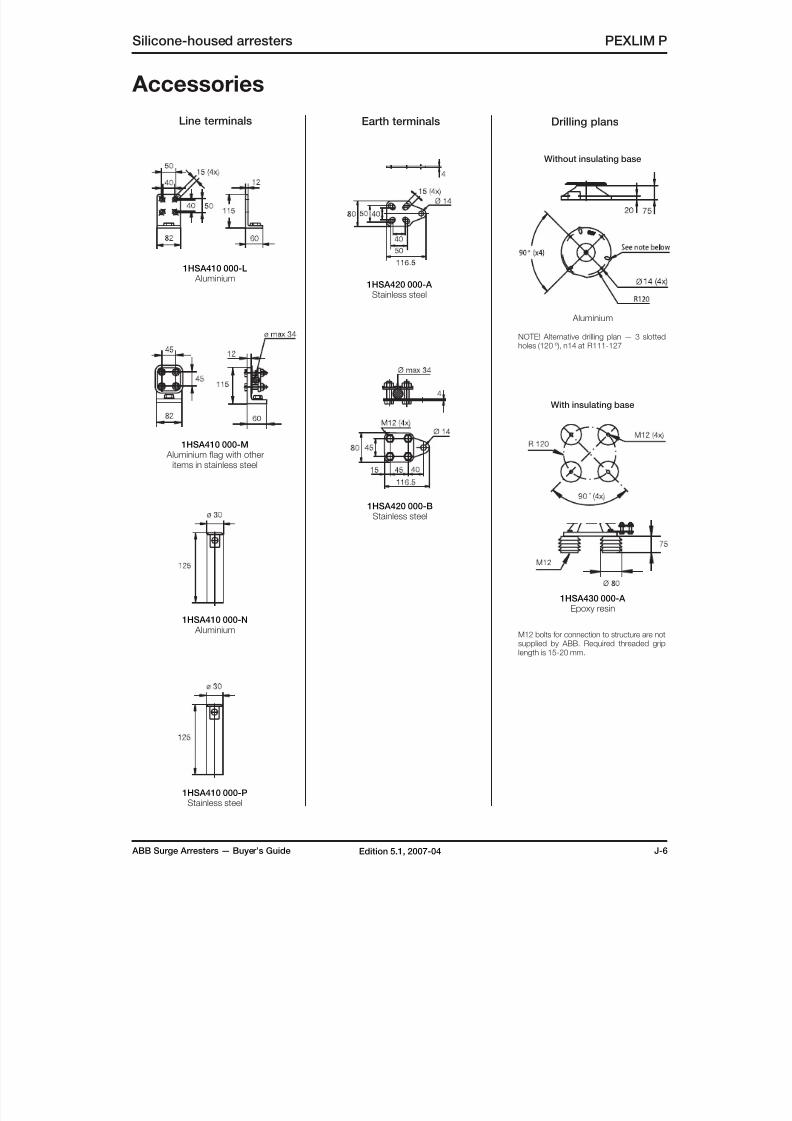
8/10/2019 ABB Extra High Voltage Surge Arresters Up to 420kV
http://slidepdf.com/reader/full/abb-extra-high-voltage-surge-arresters-up-to-420kv 45/96
ABB Surge Arresters — Buyer’s Guide J-6Edition 5.1, 2007-04
Silicone-housed arresters PEXLIM P
Accessories
1HSA410 000-L Aluminium
1HSA410 000-M Aluminium flag with other
items in stainless steel
1HSA410 000-N Aluminium
1HSA420 000-A Stainless steel
1HSA420 000-BStainless steel
1HSA430 000-A Epoxy resin
With insulating base
Without insulating base
1HSA410 000-PStainless steel
Line terminals Earth terminals
M12 bolts for connection to structure are notsupplied by ABB. Required threaded griplength is 15-20 mm.
Drilling plans
NOTE! Alternative drilling plan — 3 slottedholes (120 º), n14 at R111-127
Aluminium

8/10/2019 ABB Extra High Voltage Surge Arresters Up to 420kV
http://slidepdf.com/reader/full/abb-extra-high-voltage-surge-arresters-up-to-420kv 46/96
J-7 ABB Surge Arresters — Buyer’s GuideEdition 5.1, 2007-04
PEXLIM P Silicone-housed arresters
Shipping data
Rated
Voltage
Housing Number of arresters per crate
One Three Six
Ur
kV rms
Volume
m3
Gross
kg
Volume
m3
Gross
kg
Volume
m3
Gross
kg
24 XV024 0.1 42 0.5 86 0.9 152
30-36 XV036 0.1 42 0.5 86 0.9 152
39 XV036 0.5 52 0.5 116 0.9 212
42-72 XV052 0.5 52 0.5 116 0.9 212
54-72 XV072 0.5 52 0.5 116 0.9 212
75-84 XV072 0.7 71 0.7 163 1.2 301
75-96 XV100 0.7 71 0.7 163 1.2 301
90-120 XH123 0.7 71 0.7 163 1.2 301
90-144 XV123 0.9 87 0.9 201 1.5 372
150 XV123 0.9 87 0.9 201 1.5 372
108-120 XH145 0.7 68 0.7 154 1.2 283
108-144 XV145 0.9 87 0.9 201 1.5 372
150 XV145 0.9 87 0.9 201 1.5 372
162-168 XV145 1.1 98 1.1 239 1.9 443132-144 XH170 0.9 89 0.9 207 1.5 384
150 XH170 0.9 89 0.9 207 1.5 384
132-192 XV170 1.1 102 1.1 251 1.9 443
192 XM245 1.1 98 1.1 239 1.9 443
180-228 XH245 1.1 115 1.1 290 1.9 545
180-198 XV245 0.9 133 1.5 339 - -
210-228 XV245 0.9 133 1.5 339 - -
216-264 XH300 1.0 155 1.7 358 - -
276 XH300 1.0 155 1.7 358 - -
216-276 XV300 1.0 163 1.7 382 - -
258-288 XH362 1.6 207 2.3 435 - -
258 XV362 2.1 242 2.9 497 - -
264-288 XV362 2.1 258 2.3 545 - -
330-360 XH420 2.1 242 2.3 497 - -
Neutral-ground arresters
30-36 XN052 0.1 42 0.5 86 0.9 152
42-54 XN072 0.5 52 0.5 116 0.9 212
60 XN100 0.5 52 0.5 116 0.9 212
72 XN123 0.5 52 0.5 116 0.9 212
75-120 XN123 0.7 71 0.7 163 1.2 301
84-120 XN145 0.7 71 0.7 163 1.2 301
96-120 XN170 0.7 71 0.7 163 1.2 301
108-120 XN245 0.7 71 0.7 163 1.2 301
132-144 XN245 0.9 87 0.9 201 1.5 372
Each crate contains a certain number of arrester units
and accessories for assembly and erection. A pack-ing list is attached externally on each crate.
Each separate crate is numbered and the numbers
of all crates and their contents are listed in the shipping
specification. ABB reserves the right to pack arresters inthe most effective/economic combination. Alternate or
non-standard crates may involve additional charges.
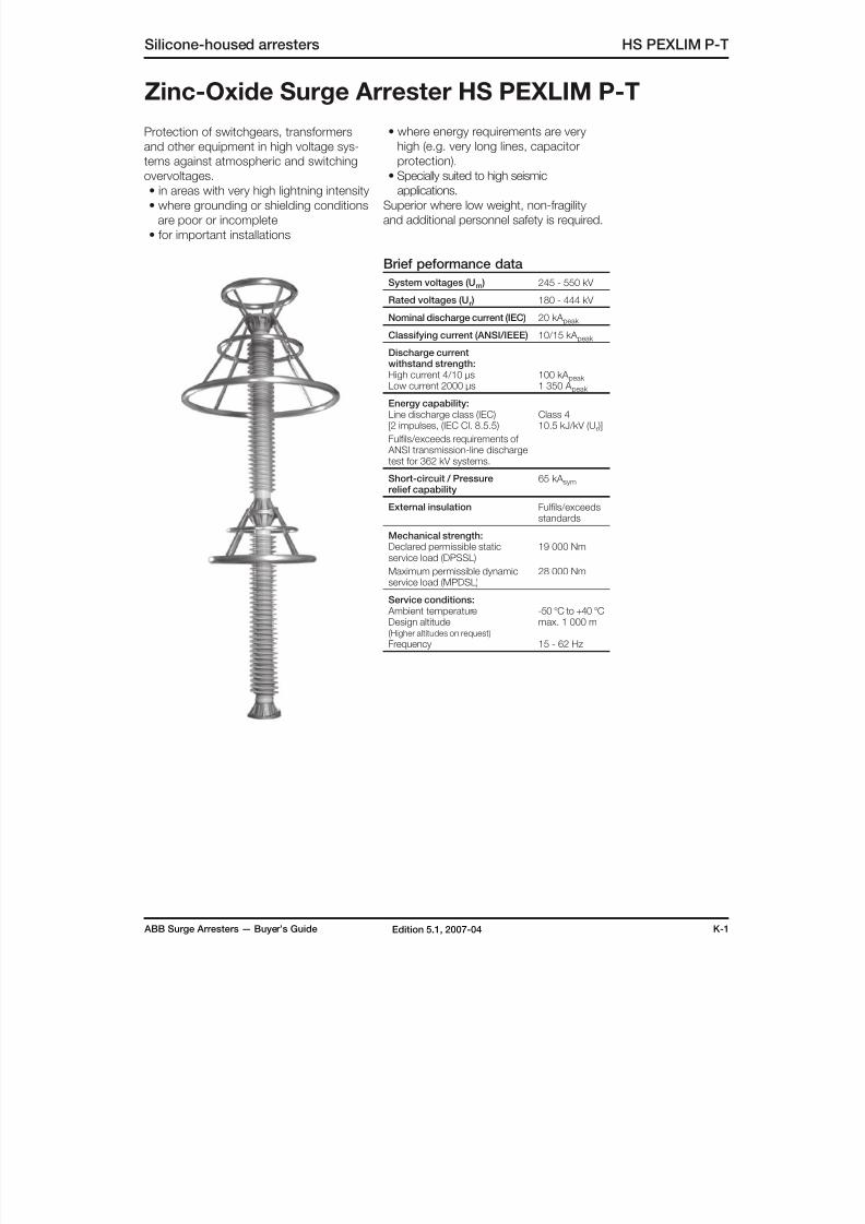
8/10/2019 ABB Extra High Voltage Surge Arresters Up to 420kV
http://slidepdf.com/reader/full/abb-extra-high-voltage-surge-arresters-up-to-420kv 47/96
ABB Surge Arresters — Buyer’s Guide K-1Edition 5.1, 2007-04
Zinc-Oxide Surge Arrester HS PEXLIM P-T
Protection of switchgears, transformers
and other equipment in high voltage sys-
tems against atmospheric and switching
overvoltages.• in areas with very high lightning intensity
• where grounding or shielding conditions
are poor or incomplete
• for important installations
• where energy requirements are very
high (e.g. very long lines, capacitor
protection).
• Specially suited to high seismicapplications.
Superior where low weight, non-fragility
and additional personnel safety is required.
Brief peformance data
System voltages (Um ) 245 - 550 kV
Rated voltages (Ur ) 180 - 444 kV
Nominal discharge current (IEC) 20 kA peak
Classifying current (ANSI/IEEE) 10/15 kA peak
Discharge current
withstand strength:High current 4/10 µsLow current 2000 µs
100 kA peak 1 350 A peak
Energy capability:Line discharge class (IEC)[2 impulses, (IEC Cl. 8.5.5)
Fulfils/exceeds requirements of ANSI transmission-line dischargetest for 362 kV systems.
Class 410.5 kJ/kV (Ur )]
Short-circuit / Pressurerelief capability
65 kA sym
External insulation Fulfils/exceedsstandards
Mechanical strength:
Declared permissible staticservice load (DPSSL)
Maximum permissible dynamicservice load (MPDSL)
19 000 Nm
28 000 Nm
Service conditions: Ambient temperatureDesign altitude(Higher altitudes on request)
Frequency
-50 °C to +40 °Cmax. 1 000 m
15 - 62 Hz
Silicone-housed arresters HS PEXLIM P-T
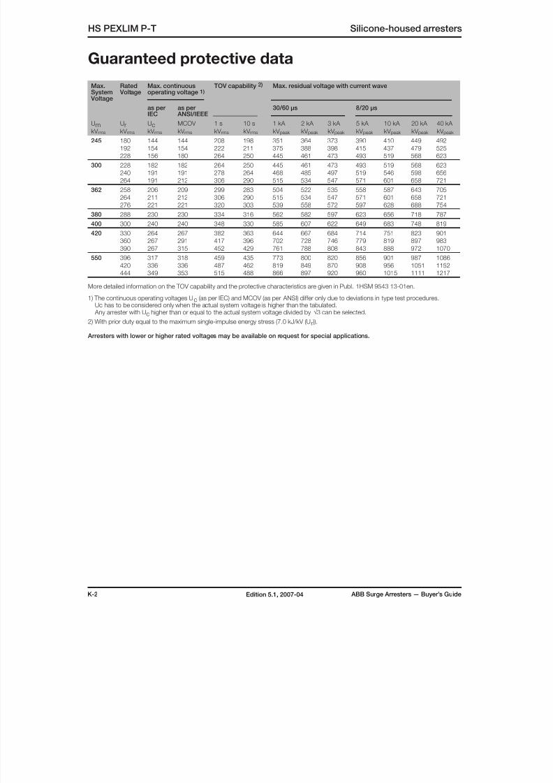
8/10/2019 ABB Extra High Voltage Surge Arresters Up to 420kV
http://slidepdf.com/reader/full/abb-extra-high-voltage-surge-arresters-up-to-420kv 48/96
K-2 ABB Surge Arresters — Buyer’s GuideEdition 5.1, 2007-04
Max.System
Voltage
Rated Voltage
Max. continuousoperating voltage 1)
TOV capability 2) Max. residual voltage with current wave
as per
IEC
as per
ANSI/IEEE
30/60 µs 8/20 µs
UmkV rms
UrkV rms
UckV rms
MCOV
kV rms
1 s
kV rms
10 s
kV rms
1 kA
kV peak
2 kA
kV peak
3 kA
kV peak
5 kA
kV peak
10 kA
kV peak
20 kA
kV peak
40 kA
kV peak
245 180 144 144 208 198 351 364 373 390 410 449 492
192 154 154 222 211 375 388 398 415 437 479 525
228 156 180 264 250 445 461 473 493 519 568 623
300 228 182 182 264 250 445 461 473 493 519 568 623
240 191 191 278 264 468 485 497 519 546 598 656
264 191 212 306 290 515 534 547 571 601 658 721
362 258 206 209 299 283 504 522 535 558 587 643 705
264 211 212 306 290 515 534 547 571 601 658 721
276 221 221 320 303 539 558 572 597 628 688 754
380 288 230 230 334 316 562 582 597 623 656 718 787
400 300 240 240 348 330 585 607 622 649 683 748 819
420 330 264 267 382 363 644 667 684 714 751 823 901360 267 291 417 396 702 728 746 779 819 897 983
390 267 315 452 429 761 788 808 843 888 972 1070
550 396 317 318 459 435 773 800 820 856 901 987 1086
420 336 336 487 462 819 849 870 908 956 1051 1152
444 349 353 515 488 866 897 920 960 1015 1111 1217
More detailed information on the TOV capability and the protective characteristics are given in Publ. 1HSM 9543 13-01en.
1) The continuous operating voltages Uc (as per IEC) and MCOV (as per ANSI) differ only due to deviations in type test procedures. Uc has to be considered only when the actual system voltage is higher than the tabulated. Any arrester with Uc higher than or equal to the actual system voltage divided by √3 can be selected.
2) With prior duty equal to the maximum single-impulse energy stress (7.0 kJ/kV (Ur )).
Arresters with lower or higher rated voltages may be available on request for special applications.
HS PEXLIM P-T Silicone-housed arresters
Guaranteed protective data
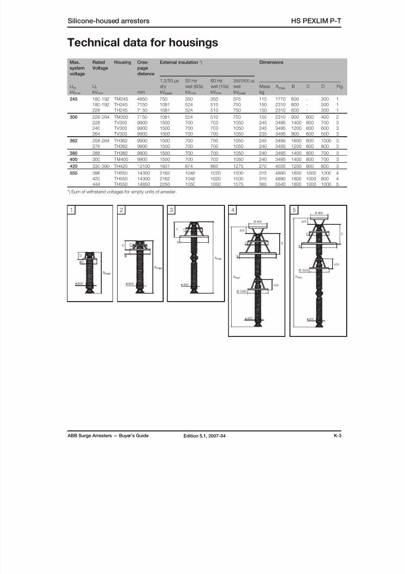
8/10/2019 ABB Extra High Voltage Surge Arresters Up to 420kV
http://slidepdf.com/reader/full/abb-extra-high-voltage-surge-arresters-up-to-420kv 49/96
ABB Surge Arresters — Buyer’s Guide K-3Edition 5.1, 2007-04
Silicone-housed arresters HS PEXLIM P-T
Technical data for housings
Max.
system
voltage
Rated
Voltage
Housing Cree-
page
distance
mm
External insulation *) Dimensions
UmkV rms
UrkV rms
1.2/50 µs
drykV peak
50 Hz
wet (60s)kV rms
60 Hz
wet (10s)kV rms
250/2500 µs
wetkV peak
Masskg
A max B C D Fig.
245 180-192 TM245 4950 750 350 350 525 115 1770 600 - 300 1
180-192 TH245 7150 1081 524 510 750 150 2310 800 - 500 1
228 TH245 7150 1081 524 510 750 150 2310 600 - 300 1
300 228-264 TM300 7150 1081 524 510 750 150 2310 900 600 400 2
228 TV300 9900 1500 700 700 1050 245 3495 1400 800 700 3
240 TV300 9900 1500 700 700 1050 245 3495 1200 800 600 3
264 TV300 9900 1500 700 700 1050 235 3495 900 600 500 3
362 258-264 TH362 9900 1500 700 700 1050 245 3495 1600 800 1000 3
276 TH362 9900 1500 700 700 1050 240 3495 1200 800 800 3
380 288 TH380 9900 1500 700 700 1050 240 3495 1400 800 700 3
400 300 TM400 9900 1500 700 700 1050 240 3495 1400 800 700 3
420 330-390 TH420 12100 1831 874 860 1275 270 4035 1200 800 800 3
550 396 TH550 14300 2162 1048 1020 1500 315 4890 1800 1000 1000 4
420 TH550 14300 2162 1048 1020 1500 315 4890 1800 1000 800 4
444 TH550 14850 2250 1050 1050 1575 365 5540 1800 1000 1000 5
*) Sum of withstand voltages for empty units of arrester.
1 542 3
D C
B
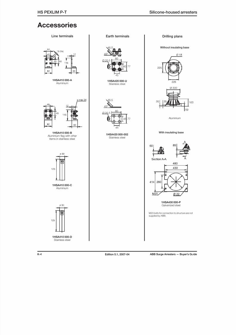
8/10/2019 ABB Extra High Voltage Surge Arresters Up to 420kV
http://slidepdf.com/reader/full/abb-extra-high-voltage-surge-arresters-up-to-420kv 50/96
K-4 ABB Surge Arresters — Buyer’s GuideEdition 5.1, 2007-04
Accessories
1HSA410 000-A Aluminium
1HSA410 000-B Aluminium flag with other
items in stainless steel
1HSA410 000-C Aluminium
1HSA420 000-UStainless steel
With insulating base
Without insulating base
1HSA410 000-DStainless steel
Line terminals Earth terminals Drilling plans
Aluminium
HS PEXLIM P-T Silicone-housed arresters
45º
46.5
80
7745
45
Ø 20.5
1HSA420 000-002Stainless steel
45º
46.5
80
7745
45
Ø 20.5
1HSA430 000-PGalvanized steel
M20 bolts for connection to structure are notsupplied by ABB.
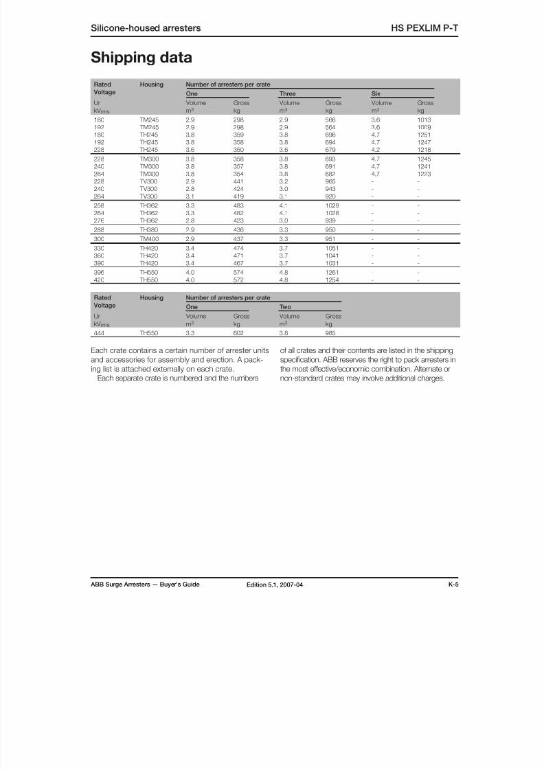
8/10/2019 ABB Extra High Voltage Surge Arresters Up to 420kV
http://slidepdf.com/reader/full/abb-extra-high-voltage-surge-arresters-up-to-420kv 51/96
ABB Surge Arresters — Buyer’s Guide K-5Edition 5.1, 2007-04
Silicone-housed arresters HS PEXLIM P-T
Shipping data
Rated
Voltage
Housing Number of arresters per crate
One Three Six
Ur
kV rms
Volume
m3
Gross
kg
Volume
m3
Gross
kg
Volume
m3
Gross
kg
180 TM245 2.9 298 2.9 566 3.6 1013
192 TM245 2.9 298 2.9 564 3.6 1009
180 TH245 3.8 359 3.8 696 4.7 1251
192 TH245 3.8 358 3.8 694 4.7 1247
228 TH245 3.6 350 3.6 679 4.2 1218
228 TM300 3.8 358 3.8 693 4.7 1245
240 TM300 3.8 357 3.8 691 4.7 1241
264 TM300 3.8 354 3.8 682 4.7 1223
228 TV300 2.9 441 3.2 965 - -
240 TV300 2.8 424 3.0 943 - -
264 TV300 3.1 419 3.1 920 - -
258 TH362 3.3 483 4.1 1029 - -
264 TH362 3.3 482 4.1 1028 - -
276 TH362 2.8 423 3.0 939 - -
288 TH380 2.9 436 3.3 950 - -300 TM400 2.9 437 3.3 951 - -
330 TH420 3.4 474 3.7 1051 - -
360 TH420 3.4 471 3.7 1041 - -
390 TH420 3.4 467 3.7 1031 - -
396 TH550 4.0 574 4.8 1261 - -
420 TH550 4.0 572 4.8 1254 - -
Rated
Voltage
Housing Number of arresters per crate
One Two
Ur
kV rms
Volume
m3
Gross
kg
Volume
m3
Gross
kg
444 TH550 3.3 602 3.8 985
Each crate contains a certain number of arrester units
and accessories for assembly and erection. A pack-
ing list is attached externally on each crate.
Each separate crate is numbered and the numbers
of all crates and their contents are listed in the shipping
specification. ABB reserves the right to pack arresters in
the most effective/economic combination. Alternate or
non-standard crates may involve additional charges.
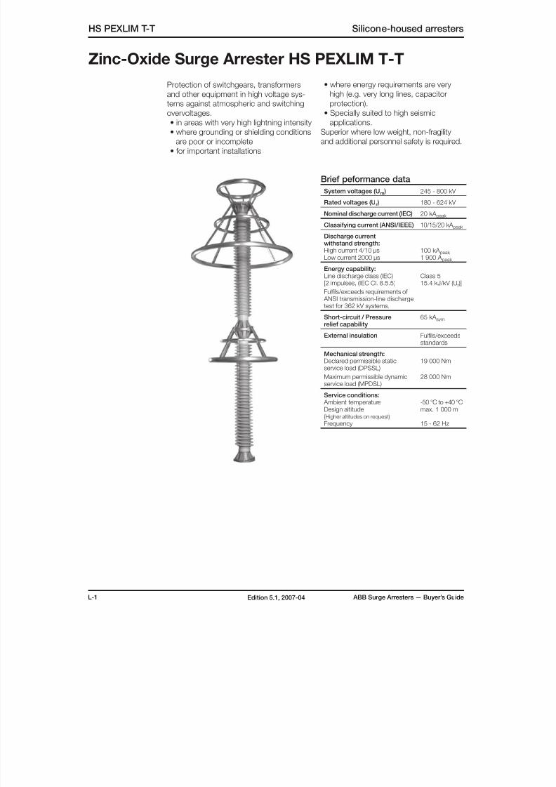
8/10/2019 ABB Extra High Voltage Surge Arresters Up to 420kV
http://slidepdf.com/reader/full/abb-extra-high-voltage-surge-arresters-up-to-420kv 52/96
L-1 ABB Surge Arresters — Buyer’s GuideEdition 5.1, 2007-04
Zinc-Oxide Surge Arrester HS PEXLIM T-T
Protection of switchgears, transformers
and other equipment in high voltage sys-
tems against atmospheric and switching
overvoltages.• in areas with very high lightning intensity
• where grounding or shielding conditions
are poor or incomplete
• for important installations
• where energy requirements are very
high (e.g. very long lines, capacitor
protection).
• Specially suited to high seismicapplications.
Superior where low weight, non-fragility
and additional personnel safety is required.
Brief peformance data
System voltages (Um ) 245 - 800 kV
Rated voltages (Ur ) 180 - 624 kV
Nominal discharge current (IEC) 20 kA peak
Classifying current (ANSI/IEEE) 10/15/20 kA peak
Discharge currentwithstand strength:High current 4/10 µsLow current 2000 µs
100 kA peak 1 900 A peak
Energy capability:Line discharge class (IEC)[2 impulses, (IEC Cl. 8.5.5)
Fulfils/exceeds requirements of ANSI transmission-line dischargetest for 362 kV systems.
Class 515.4 kJ/kV (Ur )]
Short-circuit / Pressurerelief capability
65 kA sym
External insulation Fulfils/exceedsstandards
Mechanical strength:Declared permissible staticservice load (DPSSL)
Maximum permissible dynamicservice load (MPDSL)
19 000 Nm
28 000 Nm
Service conditions: Ambient temperatureDesign altitude(Higher altitudes on request)
Frequency
-50 °C to +40 °Cmax. 1 000 m
15 - 62 Hz
HS PEXLIM T-T Silicone-housed arresters
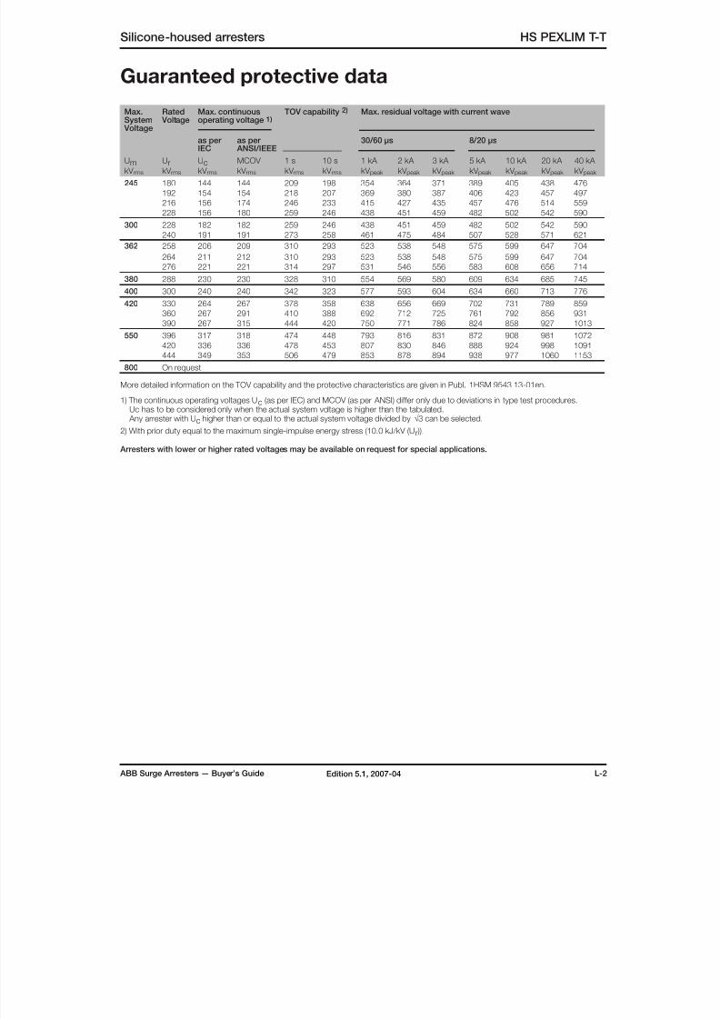
8/10/2019 ABB Extra High Voltage Surge Arresters Up to 420kV
http://slidepdf.com/reader/full/abb-extra-high-voltage-surge-arresters-up-to-420kv 53/96
ABB Surge Arresters — Buyer’s Guide L-2Edition 5.1, 2007-04
Silicone-housed arresters HS PEXLIM T-T
Max.System
Voltage
Rated Voltage
Max. continuousoperating voltage 1)
TOV capability 2) Max. residual voltage with current wave
as per
IEC
as per
ANSI/IEEE
30/60 µs 8/20 µs
UmkV rms
UrkV rms
UckV rms
MCOV
kV rms
1 s
kV rms
10 s
kV rms
1 kA
kV peak
2 kA
kV peak
3 kA
kV peak
5 kA
kV peak
10 kA
kV peak
20 kA
kV peak
40 kA
kV peak
245 180 144 144 209 198 354 364 371 389 405 438 476
192 154 154 218 207 369 380 387 406 423 457 497
216 156 174 246 233 415 427 435 457 476 514 559
228 156 180 259 246 438 451 459 482 502 542 590
300 228 182 182 259 246 438 451 459 482 502 542 590
240 191 191 273 258 461 475 484 507 528 571 621
362 258 206 209 310 293 523 538 548 575 599 647 704
264 211 212 310 293 523 538 548 575 599 647 704
276 221 221 314 297 531 546 556 583 608 656 714
380 288 230 230 328 310 554 569 580 609 634 685 745
400 300 240 240 342 323 577 593 604 634 660 713 776
420 330 264 267 378 358 638 656 669 702 731 789 859360 267 291 410 388 692 712 725 761 792 856 931
390 267 315 444 420 750 771 786 824 858 927 1013
550 396 317 318 474 448 793 816 831 872 908 981 1072
420 336 336 478 453 807 830 846 888 924 998 1091
444 349 353 506 479 853 878 894 938 977 1060 1153
800 On request
More detailed information on the TOV capability and the protective characteristics are given in Publ. 1HSM 9543 13-01en.
1) The continuous operating voltages Uc (as per IEC) and MCOV (as per ANSI) differ only due to deviations in type test procedures. Uc has to be considered only when the actual system voltage is higher than the tabulated. Any arrester with Uc higher than or equal to the actual system voltage divided by √3 can be selected.
2) With prior duty equal to the maximum single-impulse energy stress (10.0 kJ/kV (Ur )).
Arresters with lower or higher rated voltages may be available on request for special applications.
Guaranteed protective data
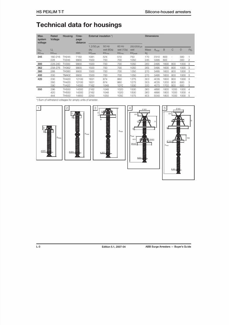
8/10/2019 ABB Extra High Voltage Surge Arresters Up to 420kV
http://slidepdf.com/reader/full/abb-extra-high-voltage-surge-arresters-up-to-420kv 54/96
L-3 ABB Surge Arresters — Buyer’s GuideEdition 5.1, 2007-04
Technical data for housings
Max.
system
voltage
Rated
Voltage
Housing Cree-
page
distance
mm
External insulation *) Dimensions
UmkV rms
UrkV rms
1.2/50 µs
dry
kV peak
50 Hz
wet (60s)
kV rms
60 Hz
wet (10s)
kV rms
250/2500 µs
wet
kV peak
Mass
kg
A max B C D Fig.
245 180-216 TH245 7150 1081 524 510 750 170 2310 600 - 300 1
228 TV245 9900 1500 700 700 1050 245 3495 600 - 300 2
300 228-240 TV300 9900 1500 700 700 1050 260 3495 1600 800 1000 3
362 258-276 TH362 9900 1500 700 700 1050 265 3495 1600 800 1000 3
380 288 TH380 9900 1500 700 700 1050 270 3495 1600 800 1000 3
400 300 TM400 9900 1500 700 700 1050 270 3495 1600 800 1000 3
420 330 TH420 12100 1831 874 860 1275 300 4035 1600 800 1000 3
360 TH420 12100 1831 874 860 1275 300 4035 1200 800 600 3
390 TV420 14300 2162 1048 1020 1500 330 4575 1200 800 600 3
550 396 TH550 14300 2162 1048 1020 1500 360 4890 1800 1000 1000 4
420 TH550 14300 2162 1048 1020 1500 360 4890 1800 1000 1000 4
444 TH550 14850 2250 1050 1050 1575 405 5540 1800 1000 1000 5*) Sum of withstand voltages for empty units of arrester.
1 542 3
HS PEXLIM T-T Silicone-housed arresters
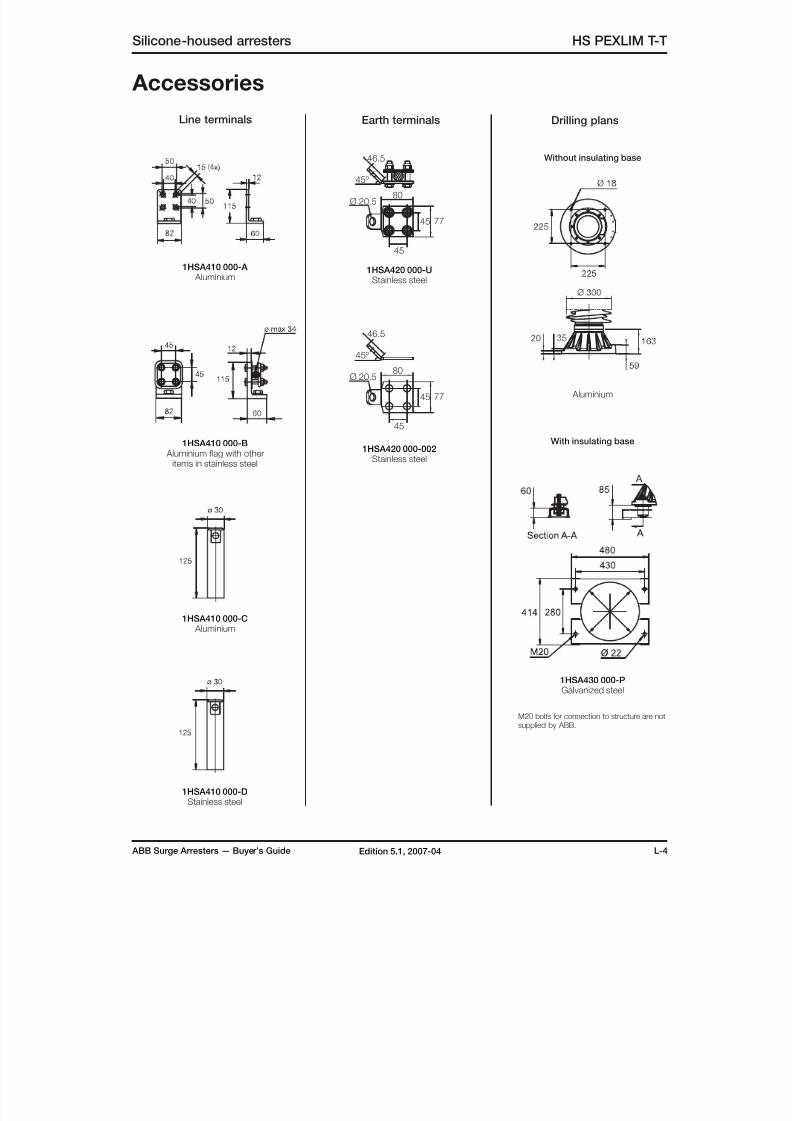
8/10/2019 ABB Extra High Voltage Surge Arresters Up to 420kV
http://slidepdf.com/reader/full/abb-extra-high-voltage-surge-arresters-up-to-420kv 55/96
ABB Surge Arresters — Buyer’s Guide L-4Edition 5.1, 2007-04
Silicone-housed arresters HS PEXLIM T-T
Accessories
1HSA410 000-A Aluminium
1HSA410 000-B Aluminium flag with other
items in stainless steel
1HSA410 000-C Aluminium
1HSA420 000-UStainless steel
1HSA430 000-PGalvanized steel
With insulating base
Without insulating base
1HSA410 000-DStainless steel
Line terminals Earth terminals
M20 bolts for connection to structure are notsupplied by ABB.
Drilling plans
Aluminium
45º
46.5
80
7745
45
Ø 20.5
1HSA420 000-002Stainless steel
45º
46.5
80
7745
45
Ø 20.5
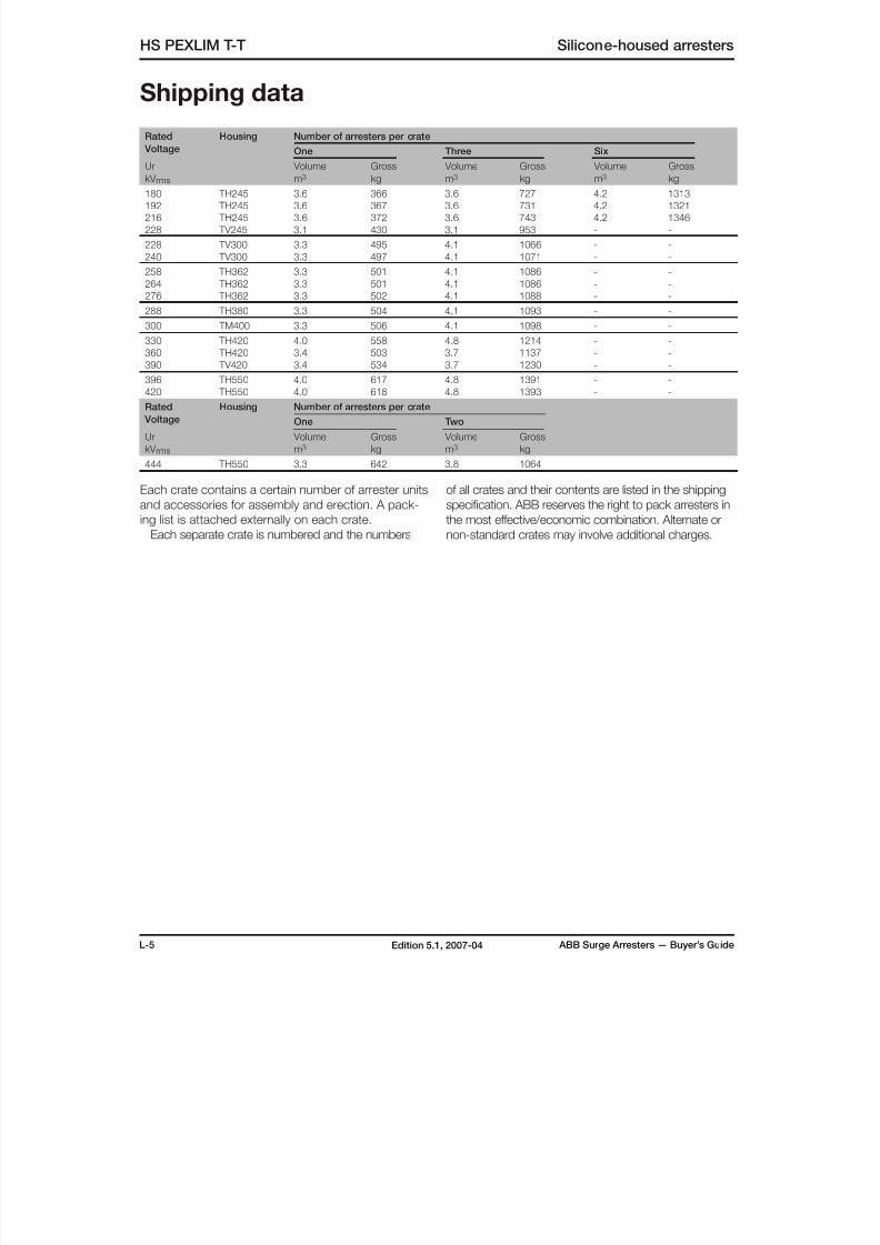
8/10/2019 ABB Extra High Voltage Surge Arresters Up to 420kV
http://slidepdf.com/reader/full/abb-extra-high-voltage-surge-arresters-up-to-420kv 56/96
L-5 ABB Surge Arresters — Buyer’s GuideEdition 5.1, 2007-04
HS PEXLIM T-T Silicone-housed arresters
Shipping data
Rated
Voltage
Housing Number of arresters per crate
One Three Six
Ur
kV rms
Volume
m3
Gross
kg
Volume
m3
Gross
kg
Volume
m3
Gross
kg
180 TH245 3.6 366 3.6 727 4.2 1313
192 TH245 3.6 367 3.6 731 4.2 1321
216 TH245 3.6 372 3.6 743 4.2 1346
228 TV245 3.1 430 3.1 953 - -
228 TV300 3.3 495 4.1 1066 - -
240 TV300 3.3 497 4.1 1071 - -
258 TH362 3.3 501 4.1 1086 - -
264 TH362 3.3 501 4.1 1086 - -
276 TH362 3.3 502 4.1 1088 - -
288 TH380 3.3 504 4.1 1093 - -
300 TM400 3.3 506 4.1 1098 - -
330 TH420 4.0 558 4.8 1214 - -
360 TH420 3.4 503 3.7 1137 - -
390 TV420 3.4 534 3.7 1230 - -
396 TH550 4.0 617 4.8 1391 - -
420 TH550 4.0 618 4.8 1393 - -
Rated
Voltage
Housing Number of arresters per crate
One Two
Ur
kV rms
Volume
m3
Gross
kg
Volume
m3
Gross
kg
444 TH550 3.3 642 3.8 1064
Each crate contains a certain number of arrester units
and accessories for assembly and erection. A pack-
ing list is attached externally on each crate.
Each separate crate is numbered and the numbers
of all crates and their contents are listed in the shipping
specification. ABB reserves the right to pack arresters in
the most effective/economic combination. Alternate or
non-standard crates may involve additional charges.
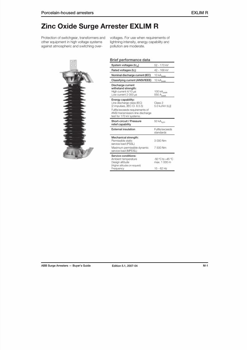
8/10/2019 ABB Extra High Voltage Surge Arresters Up to 420kV
http://slidepdf.com/reader/full/abb-extra-high-voltage-surge-arresters-up-to-420kv 57/96
ABB Surge Arresters — Buyer’s Guide M-1Edition 5.1, 2007-04
Porcelain-housed arresters EXLIM R
Protection of switchgear, transformers and
other equipment in high voltage systems
against atmospheric and switching over-
Zinc Oxide Surge Arrester EXLIM R
voltages. For use when requirements of
lightning intensity, energy capability and
pollution are moderate.
Brief performance data
System voltages (Um ) 52 - 170 kV
Rated voltages (Ur ) 42 - 168 kV
Nominal discharge current (IEC) 10 kA peak
Classifying current (ANSI/IEEE) 10 kA peak
Discharge currentwithstand strength:High current 4/10 µsLow current 2 000 µs
100 kA peak 550 A peak
Energy capability:
Line discharge class (IEC)[2 impulses, (IEC Cl. 8.5.5)
Fulfils/exceeds requirements of ANSI transmission-line dischargetest for 170 kV systems.
Class 25.0 kJ/kV (Ur )]
Short-circuit / Pressurerelief capability
50 kA sym
External insulation Fulfils/exceedsstandards
Mechanical strength:Permissible staticservice load (PSSL)
Maximum permissible dynamicservice load (MPDSL)
3 000 Nm
7 500 Nm
Service conditions: Ambient temperatureDesign altitude(Higher altitudes on request)
Frequency
-50 °C to +45 °Cmax. 1 000 m
15 - 62 Hz

8/10/2019 ABB Extra High Voltage Surge Arresters Up to 420kV
http://slidepdf.com/reader/full/abb-extra-high-voltage-surge-arresters-up-to-420kv 58/96
M-2 ABB Surge Arresters — Buyer’s GuideEdition 5.1, 2007-04
Max.System
Voltage
Rated Voltage
Max. continuousoperating voltage 1)
TOV capability 2) Max. residual voltage with current wave
as per
IEC
as per
ANSI/IEEE
30/60 µs 8/20 µs
UmkV rms
UrkV rms
UckV rms
MCOV
kV rms
1 s
kV rms
10 s
kV rms
0.5 kA
kV peak
1 kA
kV peak
2 kA
kV peak
5 kA
kV peak
10 kA
kV peak
20 kA
kV peak
40 kA
kV peak
363) 24 19.2 19.5 27.8 26.4 49.4 51.3 53.8 58.7 62.2 69.7 79.6
30 24.0 24.4 34.8 33.0 61.7 64.2 67.2 73.3 77.7 87.1 99.5
33 26.4 26.7 38.2 36.3 67.9 70.6 73.9 80.6 85.5 95.8 110
36 28.8 29.0 41.7 39.6 74.1 77.0 80.6 88.0 93.3 105 120
39 31.2 31.5 45.2 42.9 80.3 83.4 87.3 95.3 102 114 130
52 42 34 34.0 48.7 46.2 86.4 89.8 94.0 103 109 122 140
45 36 36.5 52.2 49.5 92.6 96.2 101 110 117 131 150
48 38 39.0 55.6 52.8 98.8 103 108 118 125 140 160
51 41 41.3 59.1 56.1 105 109 115 125 133 148 170
54 43 43.0 62.6 59.4 112 116 121 132 140 157 180
60 48 48.0 69.6 66.0 124 129 135 147 156 175 199
72 54 43 43.0 62.6 59.4 112 116 121 132 140 157 18060 48 48.0 69.6 66.0 124 129 135 147 156 175 199
66 53 53.4 76.5 72.6 136 142 148 162 171 192 219
72 58 58.0 83.5 79.2 149 154 162 176 187 209 239
75 60 60.7 87.0 82.5 155 161 168 184 195 218 249
84 67 68.0 97.4 92.4 173 180 188 206 218 244 279
100 75 60 60.7 87.0 82.5 155 161 168 184 195 218 249
84 67 68.0 97.4 92.4 173 180 188 206 218 244 279
90 72 72.0 104 99.0 186 193 202 220 234 262 299
96 77 77.0 111 105 198 206 215 235 249 279 319
123 90 72 72.0 104 99.0 186 193 202 220 234 262 299
96 77 77.0 111 105 198 206 215 235 249 279 319
108 78 84.0 125 118 223 231 242 264 280 314 359
120 78 98.0 139 132 247 257 269 294 311 349 398
132 78 106 153 145 272 283 296 323 342 383 438
138 78 111 160 151 284 295 309 338 358 401 458
145 108 86 86.0 125 118 223 231 242 264 280 314 359
120 92 98.0 139 132 247 257 269 294 311 349 398
132 92 106 153 145 272 283 296 323 342 383 438
138 92 111 160 151 284 295 309 338 358 401 458
144 92 115 167 158 297 308 323 352 373 418 478
170 132 106 106 153 145 272 283 296 323 342 383 438
144 108 115 167 158 297 308 323 352 373 418 478
162 108 131 187 178 334 347 363 396 420 470 538
168 108 131 194 184 346 359 376 411 436 488 557
More detailed information on the TOV capability and the protective characteristics are given in Publ. 1HSM 9543 13-01en.
1) The continuous operating voltages Uc (as per IEC) and MCOV (as per ANSI) differ only due to deviations in type test procedures. Uc has to be considered only when the actual system voltage is higher than the tabulated.
Any arrester with Uc higher than or equal to the actual system voltage divided by √3 can be selected.2) With prior duty equal to the maximum single-impulse energy stress (2.5 kJ/kV (Ur )).
3) Arresters for system voltages 36 kV or below can be supplied, on request, when the order also includes arresters for higher system voltages.
Arresters with lower or higher rated voltages may be available on request for special applications.
EXLIM R Porcelain-housed arresters
Guranteed protective data
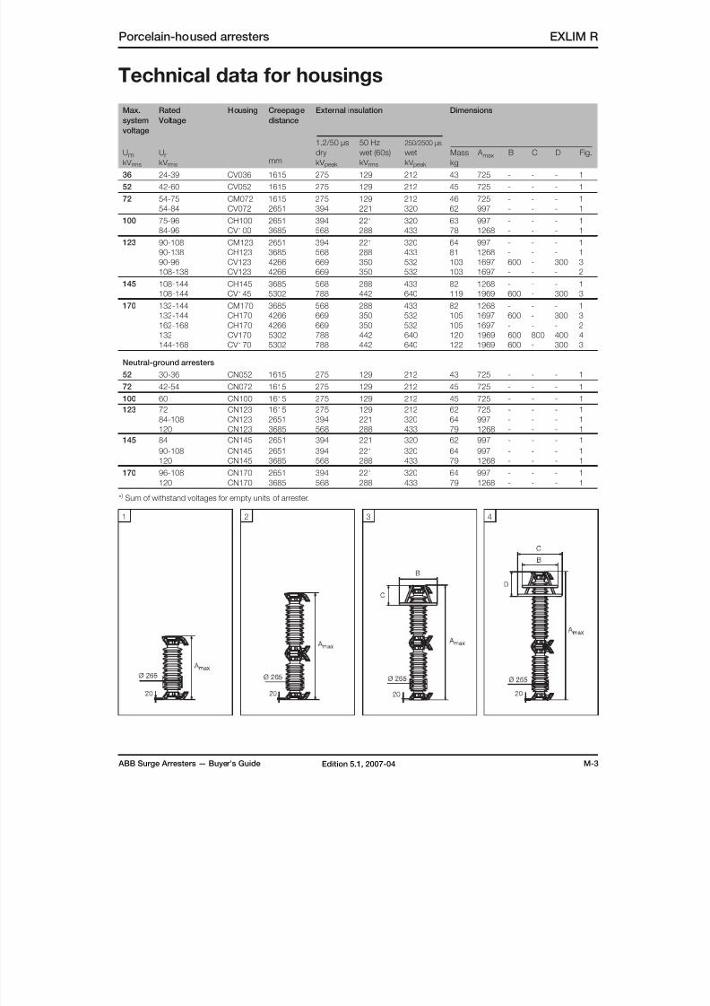
8/10/2019 ABB Extra High Voltage Surge Arresters Up to 420kV
http://slidepdf.com/reader/full/abb-extra-high-voltage-surge-arresters-up-to-420kv 59/96
ABB Surge Arresters — Buyer’s Guide M-3Edition 5.1, 2007-04
Porcelain-housed arresters EXLIM R
Technical data for housings
Max.
system
voltage
Rated
Voltage
Housing Creepage
distance
mm
External insulation Dimensions
UmkV rms
UrkV rms
1.2/50 µs
dry
kV peak
50 Hz
wet (60s)
kV rms
250/2500 µs
wet
kV peak
Mass
kg
A max B C D Fig.
36 24-39 CV036 1615 275 129 212 43 725 - - - 1
52 42-60 CV052 1615 275 129 212 45 725 - - - 1
72 54-75 CM072 1615 275 129 212 46 725 - - - 1
54-84 CV072 2651 394 221 320 62 997 - - - 1
100 75-96 CH100 2651 394 221 320 63 997 - - - 1
84-96 CV100 3685 568 288 433 78 1268 - - - 1
123 90-108 CM123 2651 394 221 320 64 997 - - - 1
90-138 CH123 3685 568 288 433 81 1268 - - - 1
90-96 CV123 4266 669 350 532 103 1697 600 - 300 3
108-138 CV123 4266 669 350 532 103 1697 - - - 2
145 108-144 CH145 3685 568 288 433 82 1268 - - - 1
108-144 CV145 5302 788 442 640 119 1969 600 - 300 3
170 132-144 CM170 3685 568 288 433 82 1268 - - - 1
132-144 CH170 4266 669 350 532 105 1697 600 - 300 3
162-168 CH170 4266 669 350 532 105 1697 - - - 2
132 CV170 5302 788 442 640 120 1969 600 800 400 4
144-168 CV170 5302 788 442 640 122 1969 600 - 300 3
Neutral-ground arresters
52 30-36 CN052 1615 275 129 212 43 725 - - - 1
72 42-54 CN072 1615 275 129 212 45 725 - - - 1
100 60 CN100 1615 275 129 212 45 725 - - - 1
123 72 CN123 1615 275 129 212 62 725 - - - 1
84-108 CN123 2651 394 221 320 64 997 - - - 1
120 CN123 3685 568 288 433 79 1268 - - - 1
145 84 CN145 2651 394 221 320 62 997 - - - 1
90-108 CN145 2651 394 221 320 64 997 - - - 1120 CN145 3685 568 288 433 79 1268 - - - 1
170 96-108 CN170 2651 394 221 320 64 997 - - - 1
120 CN170 3685 568 288 433 79 1268 - - - 1
* ) Sum of withstand voltages for empty units of arrester.
1 42 3
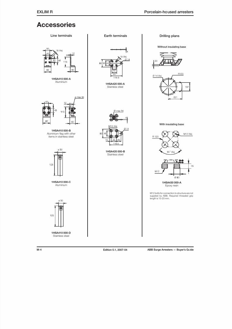
8/10/2019 ABB Extra High Voltage Surge Arresters Up to 420kV
http://slidepdf.com/reader/full/abb-extra-high-voltage-surge-arresters-up-to-420kv 60/96
M-4 ABB Surge Arresters — Buyer’s GuideEdition 5.1, 2007-04
EXLIM R Porcelain-housed arresters
Accessories
1HSA410 000-A Aluminium
1HSA410 000-B Aluminium flag with other
items in stainless steel
1HSA410 000-C Aluminium
1HSA420 000-A Stainless steel
1HSA420 000-BStainless steel
1HSA430 000-A Epoxy resin
With insulating base
Without insulating base
1HSA410 000-DStainless steel
Line terminals Earth terminals
M12 bolts for connection to structure are not
supplied by ABB. Required threaded griplength is 15-20 mm.
Drilling plans
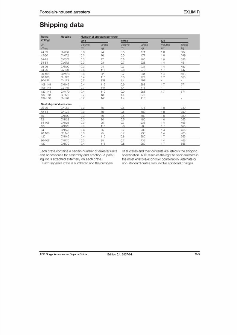
8/10/2019 ABB Extra High Voltage Surge Arresters Up to 420kV
http://slidepdf.com/reader/full/abb-extra-high-voltage-surge-arresters-up-to-420kv 61/96
ABB Surge Arresters — Buyer’s Guide M-5Edition 5.1, 2007-04
Porcelain-housed arresters EXLIM R
Rated
Voltage
Housing Number of arresters per crate
One Three Six
Ur
kV rms
Volume
m3
Gross
kg
Volume
m3
Gross
kg
Volume
m3
Gross
kg
24-39 CV036 0.3 74 0.5 171 1.0 337
42-60 CV052 0.3 76 0.5 177 1.0 349
54-75 CM072 0.3 77 0.5 180 1.0 355
54-84 CV072 0.3 93 0.7 228 1.4 451
75-96 CH100 0.3 94 0.7 231 1.4 457
84-96 CV100 0.4 115 0.8 276 1.7 547
90-108 CM123 0.3 92 0.7 234 1.4 463
90-138 CH123 0.4 116 0.8 279 1.7 553
90-138 CV123 0.7 131 1.4 367 - -
108-144 CH145 0.4 119 0.9 288 1.7 571
108-144 CV145 0.7 147 1.4 415 - -
132-144 CM170 0.4 119 0.9 288 1.7 571
132-168 CH170 0.7 133 1.4 373 - -
132-168 CV170 0.7 148 1.4 418 - -
Neutral-ground arresters
30-36 CN052 0.3 75 0.5 175 1.0 340
42-54 CN072 0.3 80 0.5 180 1.0 350
60 CN100 0.3 80 0.5 180 1.0 350
72 CN123 0.3 80 0.5 180 1.0 355
84-108 CN123 0.3 95 0.7 235 1.4 465
120 CN123 0.4 115 0.8 280 1.7 555
84 CN145 0.3 95 0.7 230 1.4 455
90-108 CN145 0.3 95 0.7 235 1.4 465
120 CN145 0.4 115 0.8 280 1.7 555
96-108 CN170 0.3 95 0.7 235 1.4 465
120 CN170 0.4 115 0.8 280 1.7 555
Shipping data
Each crate contains a certain number of arrester units
and accessories for assembly and erection. A pack-
ing list is attached externally on each crate.
Each separate crate is numbered and the numbers
of all crates and their contents are listed in the shipping
specification. ABB reserves the right to pack arresters in
the most effective/economic combination. Alternate or
non-standard crates may involve additional charges.
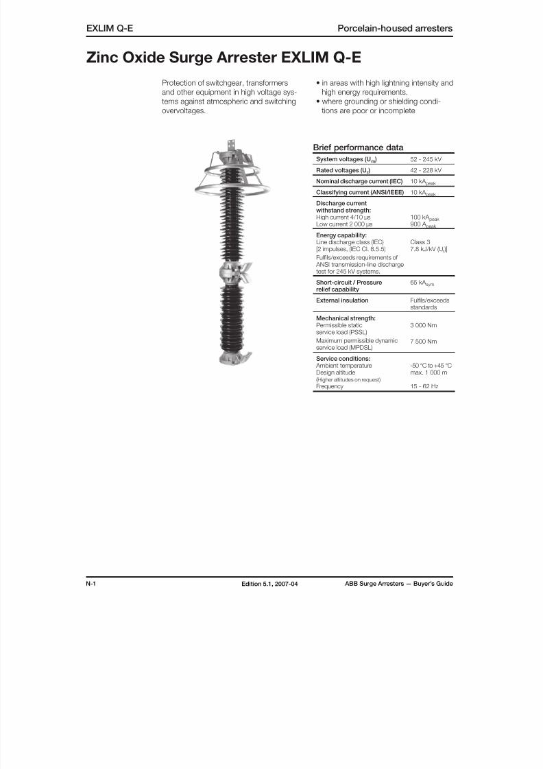
8/10/2019 ABB Extra High Voltage Surge Arresters Up to 420kV
http://slidepdf.com/reader/full/abb-extra-high-voltage-surge-arresters-up-to-420kv 62/96
N-1 ABB Surge Arresters — Buyer’s GuideEdition 5.1, 2007-04
Zinc Oxide Surge Arrester EXLIM Q-E
EXLIM Q-E Porcelain-housed arresters
Protection of switchgear, transformers
and other equipment in high voltage sys-
tems against atmospheric and switching
overvoltages.
• in areas with high lightning intensity and
high energy requirements.
• where grounding or shielding condi-
tions are poor or incomplete
Brief performance data
System voltages (Um ) 52 - 245 kV
Rated voltages (Ur ) 42 - 228 kV
Nominal discharge current (IEC) 10 kA peak
Classifying current (ANSI/IEEE) 10 kA peak
Discharge currentwithstand strength:High current 4/10 µsLow current 2 000 µs
100 kA peak 900 A peak
Energy capability:Line discharge class (IEC)[2 impulses, (IEC Cl. 8.5.5)
Fulfils/exceeds requirements of ANSI transmission-line dischargetest for 245 kV systems.
Class 37.8 kJ/kV (Ur )]
Short-circuit / Pressurerelief capability
65 kA sym
External insulation Fulfils/exceedsstandards
Mechanical strength:Permissible staticservice load (PSSL)
Maximum permissible dynamicservice load (MPDSL)
3 000 Nm
7 500 Nm
Service conditions: Ambient temperatureDesign altitude(Higher altitudes on request)
Frequency
-50 °C to +45 °Cmax. 1 000 m
15 - 62 Hz
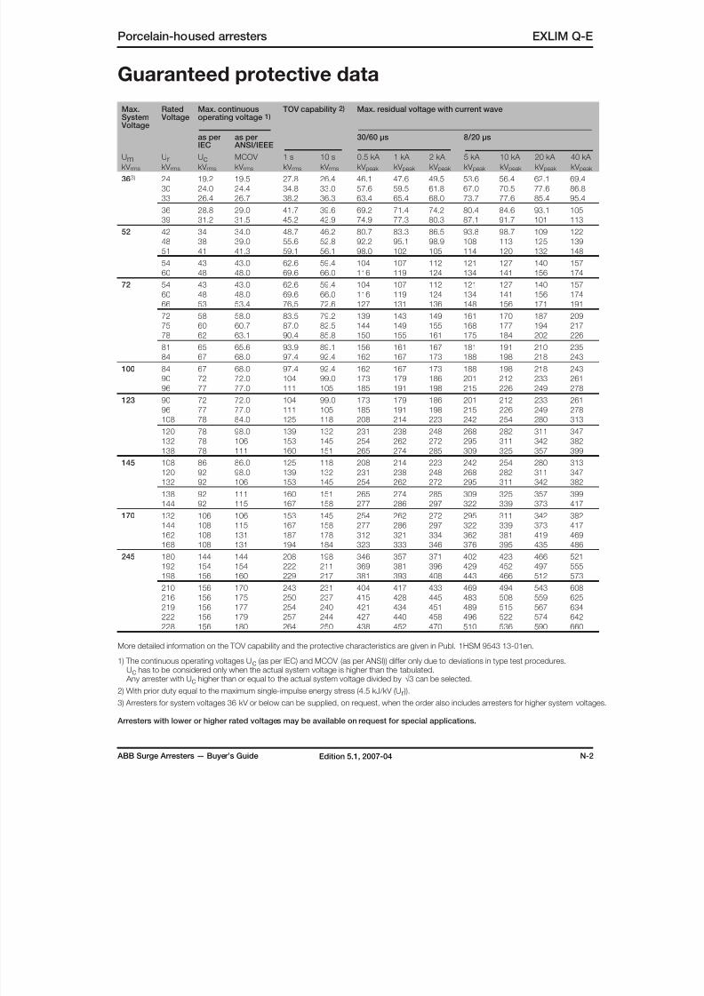
8/10/2019 ABB Extra High Voltage Surge Arresters Up to 420kV
http://slidepdf.com/reader/full/abb-extra-high-voltage-surge-arresters-up-to-420kv 63/96
ABB Surge Arresters — Buyer’s Guide N-2Edition 5.1, 2007-04
Porcelain-housed arresters EXLIM Q-E
Guaranteed protective data
Max.System
Voltage
Rated Voltage
Max. continuousoperating voltage 1)
TOV capability 2) Max. residual voltage with current wave
as per
IEC
as per
ANSI/IEEE
30/60 µs 8/20 µs
UmkV rms
UrkV rms
UckV rms
MCOV
kV rms
1 s
kV rms
10 s
kV rms
0.5 kA
kV peak
1 kA
kV peak
2 kA
kV peak
5 kA
kV peak
10 kA
kV peak
20 kA
kV peak
40 kA
kV peak
363) 24 19.2 19.5 27.8 26.4 46.1 47.6 49.5 53.6 56.4 62.1 69.4
30 24.0 24.4 34.8 33.0 57.6 59.5 61.8 67.0 70.5 77.6 86.8
33 26.4 26.7 38.2 36.3 63.4 65.4 68.0 73.7 77.6 85.4 95.4
36 28.8 29.0 41.7 39.6 69.2 71.4 74.2 80.4 84.6 93.1 105
39 31.2 31.5 45.2 42.9 74.9 77.3 80.3 87.1 91.7 101 113
52 42 34 34.0 48.7 46.2 80.7 83.3 86.5 93.8 98.7 109 122
48 38 39.0 55.6 52.8 92.2 95.1 98.9 108 113 125 139
51 41 41.3 59.1 56.1 98.0 102 105 114 120 132 148
54 43 43.0 62.6 59.4 104 107 112 121 127 140 157
60 48 48.0 69.6 66.0 116 119 124 134 141 156 174
72 54 43 43.0 62.6 59.4 104 107 112 121 127 140 157
60 48 48.0 69.6 66.0 116 119 124 134 141 156 17466 53 53.4 76.5 72.6 127 131 136 148 156 171 191
72 58 58.0 83.5 79.2 139 143 149 161 170 187 209
75 60 60.7 87.0 82.5 144 149 155 168 177 194 217
78 62 63.1 90.4 85.8 150 155 161 175 184 202 226
81 65 65.6 93.9 89.1 156 161 167 181 191 210 235
84 67 68.0 97.4 92.4 162 167 173 188 198 218 243
100 84 67 68.0 97.4 92.4 162 167 173 188 198 218 243
90 72 72.0 104 99.0 173 179 186 201 212 233 261
96 77 77.0 111 105 185 191 198 215 226 249 278
123 90 72 72.0 104 99.0 173 179 186 201 212 233 261
96 77 77.0 111 105 185 191 198 215 226 249 278
108 78 84.0 125 118 208 214 223 242 254 280 313
120 78 98.0 139 132 231 238 248 268 282 311 347
132 78 106 153 145 254 262 272 295 311 342 382138 78 111 160 151 265 274 285 309 325 357 399
145 108 86 86.0 125 118 208 214 223 242 254 280 313
120 92 98.0 139 132 231 238 248 268 282 311 347
132 92 106 153 145 254 262 272 295 311 342 382
138 92 111 160 151 265 274 285 309 325 357 399
144 92 115 167 158 277 286 297 322 339 373 417
170 132 106 106 153 145 254 262 272 295 311 342 382
144 108 115 167 158 277 286 297 322 339 373 417
162 108 131 187 178 312 321 334 362 381 419 469
168 108 131 194 184 323 333 346 376 395 435 486
245 180 144 144 208 198 346 357 371 402 423 466 521
192 154 154 222 211 369 381 396 429 452 497 555
198 156 160 229 217 381 393 408 443 466 512 573
210 156 170 243 231 404 417 433 469 494 543 608
216 156 175 250 237 415 428 445 483 508 559 625
219 156 177 254 240 421 434 451 489 515 567 634
222 156 179 257 244 427 440 458 496 522 574 642
228 156 180 264 250 438 452 470 510 536 590 660
More detailed information on the TOV capability and the protective characteristics are given in Publ. 1HSM 9543 13-01en.
1) The continuous operating voltages Uc (as per IEC) and MCOV (as per ANSI)) differ only due to deviations in type test procedures. Uc has to be considered only when the actual system voltage is higher than the tabulated. Any arrester with Uc higher than or equal to the actual system voltage divided by √3 can be selected.
2) With prior duty equal to the maximum single-impulse energy stress (4.5 kJ/kV (Ur )).
3) Arresters for system voltages 36 kV or below can be supplied, on request, when the order also includes arresters for higher system voltages.
Arresters with lower or higher rated voltages may be available on request for special applications.
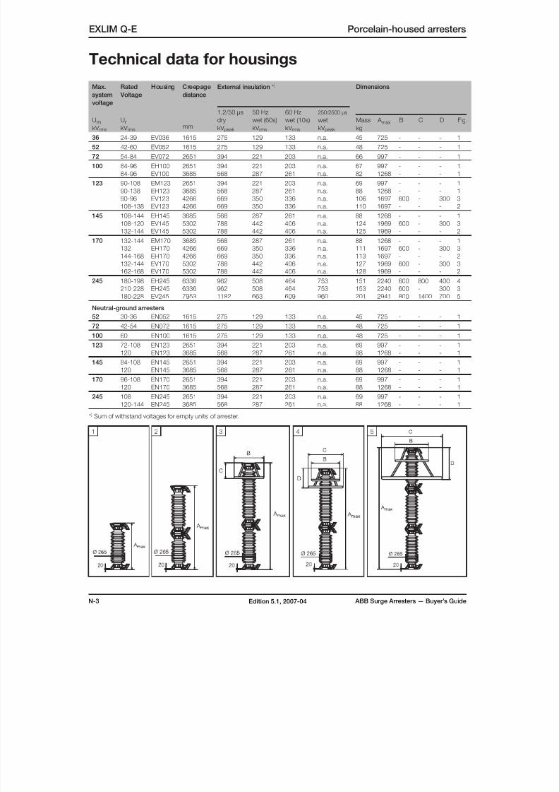
8/10/2019 ABB Extra High Voltage Surge Arresters Up to 420kV
http://slidepdf.com/reader/full/abb-extra-high-voltage-surge-arresters-up-to-420kv 64/96
N-3 ABB Surge Arresters — Buyer’s GuideEdition 5.1, 2007-04
Technical data for housings
EXLIM Q-E Porcelain-housed arresters
Max.
system
voltage
Rated
Voltage
Housing Creepage
distance
mm
External insulation * ) Dimensions
UmkV rms
UrkV rms
1.2/50 µs
dry
kV peak
50 Hz
wet (60s)
kV rms
60 Hz
wet (10s)
kV rms
250/2500 µs
wet
kV peak
Mass
kg
A max B C D Fig.
36 24-39 EV036 1615 275 129 133 n.a. 45 725 - - - 1
52 42-60 EV052 1615 275 129 133 n.a. 48 725 - - - 1
72 54-84 EV072 2651 394 221 203 n.a. 66 997 - - - 1
100 84-96 EH100 2651 394 221 203 n.a. 67 997 - - - 1
84-96 EV100 3685 568 287 261 n.a. 82 1268 - - - 1
123 90-108 EM123 2651 394 221 203 n.a. 69 997 - - - 1
90-138 EH123 3685 568 287 261 n.a. 88 1268 - - - 1
90-96 EV123 4266 669 350 336 n.a. 106 1697 600 - 300 3
108-138 EV123 4266 669 350 336 n.a. 110 1697 - - - 2
145 108-144 EH145 3685 568 287 261 n.a. 88 1268 - - - 1
108-120 EV145 5302 788 442 406 n.a. 124 1969 600 - 300 3
132-144 EV145 5302 788 442 406 n.a. 125 1969 - - - 2
170 132-144 EM170 3685 568 287 261 n.a. 88 1268 - - - 1
132 EH170 4266 669 350 336 n.a. 111 1697 600 - 300 3
144-168 EH170 4266 669 350 336 n.a. 113 1697 - - - 2
132-144 EV170 5302 788 442 406 n.a. 127 1969 600 - 300 3
162-168 EV170 5302 788 442 406 n.a. 128 1969 - - - 2
245 180-198 EH245 6336 962 508 464 753 151 2240 600 800 400 4
210-228 EH245 6336 962 508 464 753 153 2240 600 - 300 3
180-228 EV245 7953 1182 663 609 960 201 2941 800 1400 700 5
Neutral-ground arresters
52 30-36 EN052 1615 275 129 133 n.a. 45 725 - - - 1
72 42-54 EN072 1615 275 129 133 n.a. 48 725 - - - 1
100 60 EN100 1615 275 129 133 n.a. 48 725 - - - 1
123 72-108 EN123 2651 394 221 203 n.a. 69 997 - - - 1
120 EN123 3685 568 287 261 n.a. 88 1268 - - - 1145 84-108 EN145 2651 394 221 203 n.a. 69 997 - - - 1
120 EN145 3685 568 287 261 n.a. 88 1268 - - - 1
170 96-108 EN170 2651 394 221 203 n.a. 69 997 - - - 1
120 EN170 3685 568 287 261 n.a. 88 1268 - - - 1
245 108 EN245 2651 394 221 203 n.a. 69 997 - - - 1
120-144 EN245 3685 568 287 261 n.a. 88 1268 - - - 1
* ) Sum of withstand voltages for empty units of arrester.
1 2 3 4 5
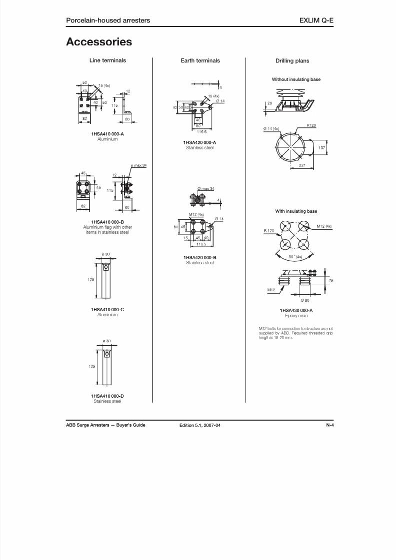
8/10/2019 ABB Extra High Voltage Surge Arresters Up to 420kV
http://slidepdf.com/reader/full/abb-extra-high-voltage-surge-arresters-up-to-420kv 65/96
ABB Surge Arresters — Buyer’s Guide N-4Edition 5.1, 2007-04
Porcelain-housed arresters EXLIM Q-E
Accessories
1HSA410 000-A Aluminium
1HSA410 000-B Aluminium flag with other
items in stainless steel
1HSA410 000-C Aluminium
1HSA420 000-A Stainless steel
1HSA420 000-BStainless steel
1HSA430 000-A Epoxy resin
With insulating base
Without insulating base
1HSA410 000-DStainless steel
Line terminals Earth terminals
M12 bolts for connection to structure are not
supplied by ABB. Required threaded griplength is 15-20 mm.
Drilling plans
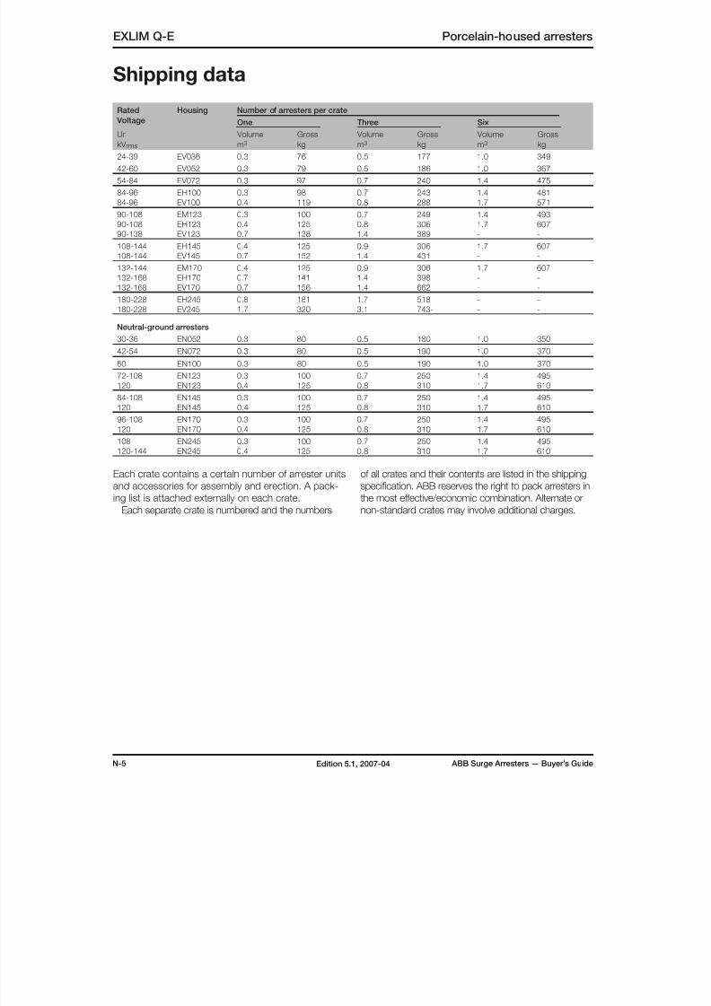
8/10/2019 ABB Extra High Voltage Surge Arresters Up to 420kV
http://slidepdf.com/reader/full/abb-extra-high-voltage-surge-arresters-up-to-420kv 66/96
N-5 ABB Surge Arresters — Buyer’s GuideEdition 5.1, 2007-04
EXLIM Q-E Porcelain-housed arresters
Shipping data
Rated
Voltage
Housing Number of arresters per crate
One Three Six
Ur
kV rms
Volume
m3
Gross
kg
Volume
m3
Gross
kg
Volume
m3
Gross
kg
24-39 EV036 0.3 76 0.5 177 1.0 349
42-60 EV052 0.3 79 0.5 186 1.0 367
54-84 EV072 0.3 97 0.7 240 1.4 475
84-96 EH100 0.3 98 0.7 243 1.4 481
84-96 EV100 0.4 119 0.8 288 1.7 571
90-108 EM123 0.3 100 0.7 249 1.4 493
90-108 EH123 0.4 125 0.8 306 1.7 607
90-138 EV123 0.7 138 1.4 389 - -
108-144 EH145 0.4 125 0.9 306 1.7 607
108-144 EV145 0.7 152 1.4 431 - -
132-144 EM170 0.4 125 0.9 306 1.7 607
132-168 EH170 0.7 141 1.4 398 - -
132-168 EV170 0.7 156 1.4 662 - -
180-228 EH245 0.8 181 1.7 518 - -180-228 EV245 1.7 320 3.1 743- - -
Neutral-ground arresters
30-36 EN052 0.3 80 0.5 180 1.0 350
42-54 EN072 0.3 80 0.5 190 1.0 370
60 EN100 0.3 80 0.5 190 1.0 370
72-108 EN123 0.3 100 0.7 250 1.4 495
120 EN123 0.4 125 0.8 310 1.7 610
84-108 EN145 0.3 100 0.7 250 1.4 495
120 EN145 0.4 125 0.8 310 1.7 610
96-108 EN170 0.3 100 0.7 250 1.4 495
120 EN170 0.4 125 0.8 310 1.7 610
108 EN245 0.3 100 0.7 250 1.4 495
120-144 EN245 0.4 125 0.8 310 1.7 610
Each crate contains a certain number of arrester units
and accessories for assembly and erection. A pack-
ing list is attached externally on each crate.
Each separate crate is numbered and the numbers
of all crates and their contents are listed in the shipping
specification. ABB reserves the right to pack arresters in
the most effective/economic combination. Alternate or
non-standard crates may involve additional charges.
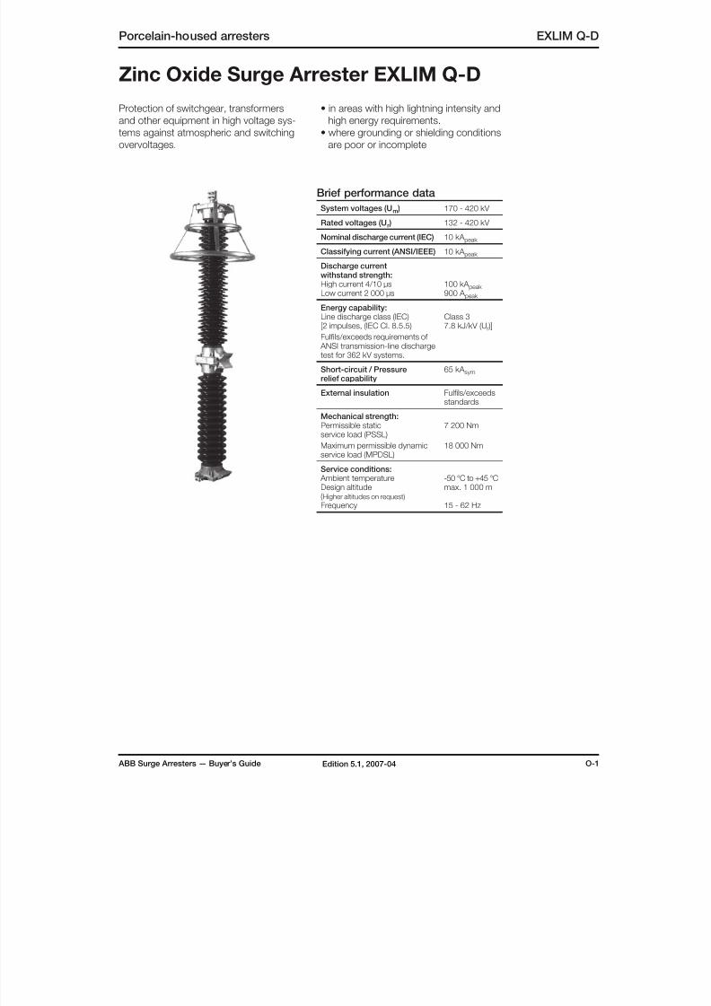
8/10/2019 ABB Extra High Voltage Surge Arresters Up to 420kV
http://slidepdf.com/reader/full/abb-extra-high-voltage-surge-arresters-up-to-420kv 67/96
ABB Surge Arresters — Buyer’s Guide O-1Edition 5.1, 2007-04
Porcelain-housed arresters EXLIM Q-D
Zinc Oxide Surge Arrester EXLIM Q-D
Protection of switchgear, transformers
and other equipment in high voltage sys-
tems against atmospheric and switching
overvoltages.
• in areas with high lightning intensity and
high energy requirements.
• where grounding or shielding conditions
are poor or incomplete
Brief performance data
System voltages (Um ) 170 - 420 kV
Rated voltages (Ur ) 132 - 420 kV
Nominal discharge current (IEC) 10 kA peak
Classifying current (ANSI/IEEE) 10 kA peak
Discharge currentwithstand strength:High current 4/10 µsLow current 2 000 µs
100 kA peak 900 A peak
Energy capability:Line discharge class (IEC)[2 impulses, (IEC Cl. 8.5.5)
Fulfils/exceeds requirements of ANSI transmission-line dischargetest for 362 kV systems.
Class 37.8 kJ/kV (Ur )]
Short-circuit / Pressurerelief capability
65 kA sym
External insulation Fulfils/exceedsstandards
Mechanical strength:Permissible staticservice load (PSSL)
Maximum permissible dynamicservice load (MPDSL)
7 200 Nm
18 000 Nm
Service conditions: Ambient temperatureDesign altitude(Higher altitudes on request)
Frequency
-50 °C to +45 °Cmax. 1 000 m
15 - 62 Hz
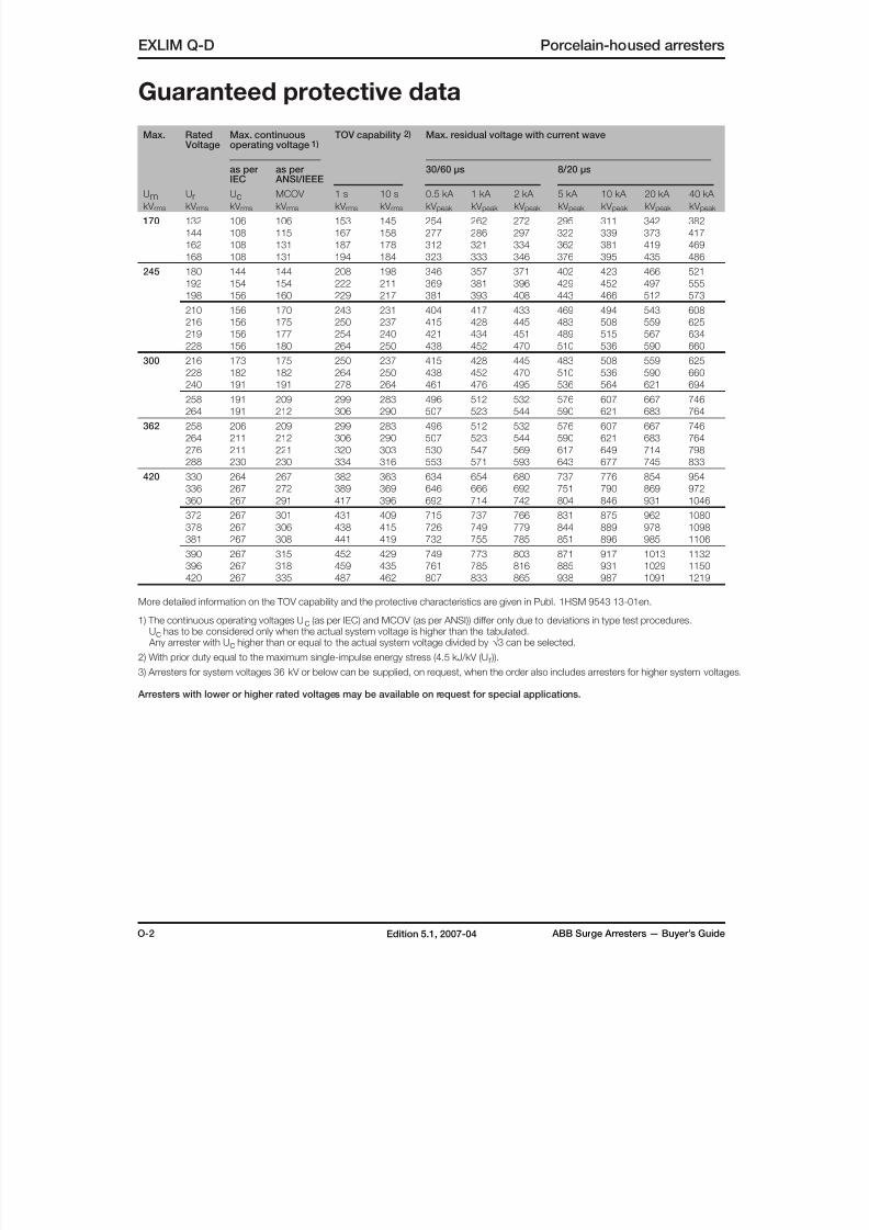
8/10/2019 ABB Extra High Voltage Surge Arresters Up to 420kV
http://slidepdf.com/reader/full/abb-extra-high-voltage-surge-arresters-up-to-420kv 68/96
O-2 ABB Surge Arresters — Buyer’s GuideEdition 5.1, 2007-04
Max. Rated Voltage
Max. continuousoperating voltage 1)
TOV capability 2) Max. residual voltage with current wave
as per
IEC
as per
ANSI/IEEE
30/60 µs 8/20 µs
UmkV rms
UrkV rms
UckV rms
MCOV
kV rms
1 s
kV rms
10 s
kV rms
0.5 kA
kV peak
1 kA
kV peak
2 kA
kV peak
5 kA
kV peak
10 kA
kV peak
20 kA
kV peak
40 kA
kV peak
170 132 106 106 153 145 254 262 272 295 311 342 382
144 108 115 167 158 277 286 297 322 339 373 417
162 108 131 187 178 312 321 334 362 381 419 469
168 108 131 194 184 323 333 346 376 395 435 486
245 180 144 144 208 198 346 357 371 402 423 466 521
192 154 154 222 211 369 381 396 429 452 497 555
198 156 160 229 217 381 393 408 443 466 512 573
210 156 170 243 231 404 417 433 469 494 543 608
216 156 175 250 237 415 428 445 483 508 559 625
219 156 177 254 240 421 434 451 489 515 567 634
228 156 180 264 250 438 452 470 510 536 590 660
300 216 173 175 250 237 415 428 445 483 508 559 625
228 182 182 264 250 438 452 470 510 536 590 660
240 191 191 278 264 461 476 495 536 564 621 694
258 191 209 299 283 496 512 532 576 607 667 746
264 191 212 306 290 507 523 544 590 621 683 764
362 258 206 209 299 283 496 512 532 576 607 667 746
264 211 212 306 290 507 523 544 590 621 683 764
276 211 221 320 303 530 547 569 617 649 714 798
288 230 230 334 316 553 571 593 643 677 745 833
420 330 264 267 382 363 634 654 680 737 776 854 954
336 267 272 389 369 646 666 692 751 790 869 972
360 267 291 417 396 692 714 742 804 846 931 1046
372 267 301 431 409 715 737 766 831 875 962 1080
378 267 306 438 415 726 749 779 844 889 978 1098
381 267 308 441 419 732 755 785 851 896 985 1106
390 267 315 452 429 749 773 803 871 917 1013 1132
396 267 318 459 435 761 785 816 885 931 1029 1150
420 267 335 487 462 807 833 865 938 987 1091 1219
More detailed information on the TOV capability and the protective characteristics are given in Publ. 1HSM 9543 13-01en.
1) The continuous operating voltages Uc (as per IEC) and MCOV (as per ANSI)) differ only due to deviations in type test procedures. Uc has to be considered only when the actual system voltage is higher than the tabulated. Any arrester with Uc higher than or equal to the actual system voltage divided by √3 can be selected.
2) With prior duty equal to the maximum single-impulse energy stress (4.5 kJ/kV (Ur )).
3) Arresters for system voltages 36 kV or below can be supplied, on request, when the order also includes arresters for higher system voltages.
Arresters with lower or higher rated voltages may be available on request for special applications.
EXLIM Q-D Porcelain-housed arresters
Guaranteed protective data
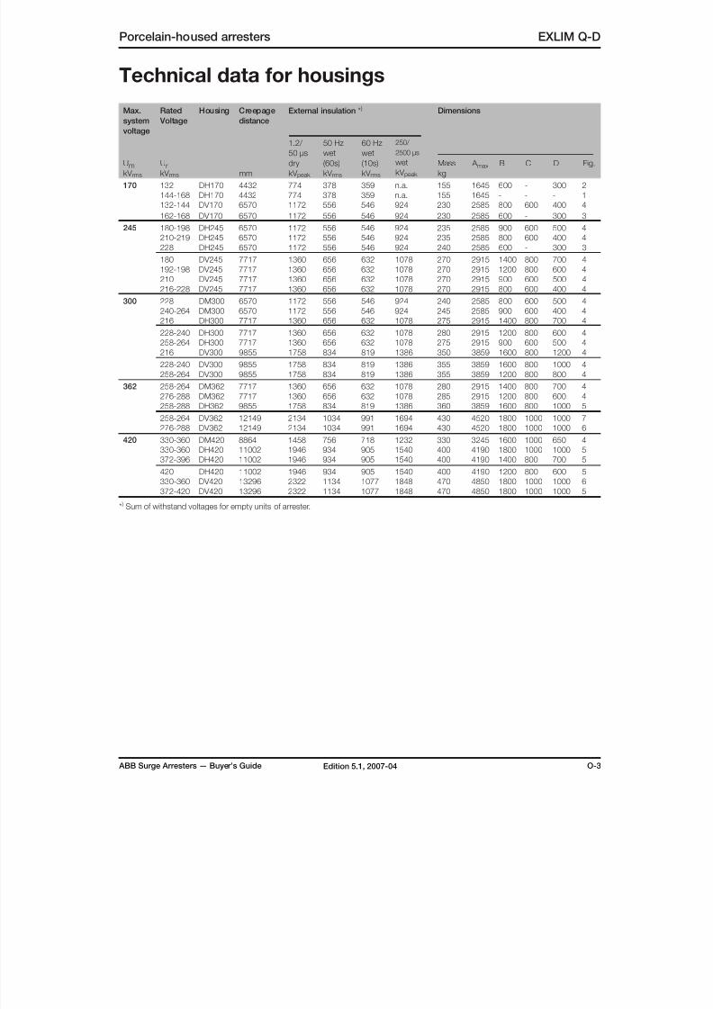
8/10/2019 ABB Extra High Voltage Surge Arresters Up to 420kV
http://slidepdf.com/reader/full/abb-extra-high-voltage-surge-arresters-up-to-420kv 69/96
ABB Surge Arresters — Buyer’s Guide O-3Edition 5.1, 2007-04
Porcelain-housed arresters EXLIM Q-D
Technical data for housings
Max.
system
voltage
Rated
Voltage
Housing Creepage
distance
External insulation * ) Dimensions
UmkV rms
UrkV rms mm
1.2/
50 µs
dry
kV peak
50 Hz
wet
(60s)
kV rms
60 Hz
wet
(10s)
kV rms
250/
2500 µs
wet
kV peak
Mass
kg
A max B C D Fig.
170 132 DH170 4432 774 378 359 n.a. 155 1645 600 - 300 2
144-168 DH170 4432 774 378 359 n.a. 155 1645 - - - 1
132-144 DV170 6570 1172 556 546 924 230 2585 800 600 400 4
162-168 DV170 6570 1172 556 546 924 230 2585 600 - 300 3
245 180-198 DH245 6570 1172 556 546 924 235 2585 900 600 500 4
210-219 DH245 6570 1172 556 546 924 235 2585 800 600 400 4
228 DH245 6570 1172 556 546 924 240 2585 600 - 300 3
180 DV245 7717 1360 656 632 1078 270 2915 1400 800 700 4
192-198 DV245 7717 1360 656 632 1078 270 2915 1200 800 600 4
210 DV245 7717 1360 656 632 1078 270 2915 900 600 500 4
216-228 DV245 7717 1360 656 632 1078 270 2915 800 600 400 4
300 228 DM300 6570 1172 556 546 924 240 2585 800 600 500 4240-264 DM300 6570 1172 556 546 924 245 2585 900 600 400 4
216 DH300 7717 1360 656 632 1078 275 2915 1400 800 700 4
228-240 DH300 7717 1360 656 632 1078 280 2915 1200 800 600 4
258-264 DH300 7717 1360 656 632 1078 275 2915 900 600 500 4
216 DV300 9855 1758 834 819 1386 350 3859 1600 800 1200 4
228-240 DV300 9855 1758 834 819 1386 355 3859 1600 800 1000 4
258-264 DV300 9855 1758 834 819 1386 355 3859 1200 800 800 4
362 258-264 DM362 7717 1360 656 632 1078 280 2915 1400 800 700 4
276-288 DM362 7717 1360 656 632 1078 285 2915 1200 800 600 4
258-288 DH362 9855 1758 834 819 1386 360 3859 1600 800 1000 5
258-264 DV362 12149 2134 1034 991 1694 430 4520 1800 1000 1000 7
276-288 DV362 12149 2134 1034 991 1694 430 4520 1800 1000 1000 6
420 330-360 DM420 8864 1458 756 718 1232 330 3245 1600 1000 650 4
330-360 DH420 11002 1946 934 905 1540 400 4190 1800 1000 1000 5372-396 DH420 11002 1946 934 905 1540 400 4190 1400 800 700 5
420 DH420 11002 1946 934 905 1540 400 4190 1200 800 600 5
330-360 DV420 13296 2322 1134 1077 1848 470 4850 1800 1000 1000 6
372-420 DV420 13296 2322 1134 1077 1848 470 4850 1800 1000 1000 5
* ) Sum of withstand voltages for empty units of arrester.
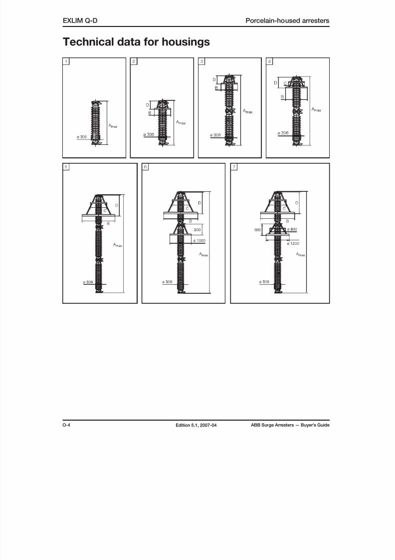
8/10/2019 ABB Extra High Voltage Surge Arresters Up to 420kV
http://slidepdf.com/reader/full/abb-extra-high-voltage-surge-arresters-up-to-420kv 70/96
O-4 ABB Surge Arresters — Buyer’s GuideEdition 5.1, 2007-04
EXLIM Q-D Porcelain-housed arresters
Technical data for housings
1
5
42 3
76

8/10/2019 ABB Extra High Voltage Surge Arresters Up to 420kV
http://slidepdf.com/reader/full/abb-extra-high-voltage-surge-arresters-up-to-420kv 71/96
ABB Surge Arresters — Buyer’s Guide O-5Edition 5.1, 2007-04
Porcelain-housed arresters EXLIM Q-D
Accessories
1HSA410 000-A Aluminium
1HSA410 000-B Aluminium flag with other
items in stainless steel
1HSA410 000-C Aluminium
1HSA420 000-CStainless steel
1HSA420 000-DStainless steel
1HSA430 000-CEpoxy resin
With insulating base
Without insulating base
1HSA410 000-DStainless steel
Line terminals Earth terminals
M16 bolts for connection to structure are notsupplied by ABB. Required threaded griplength is 15-20 mm.
Drilling plans
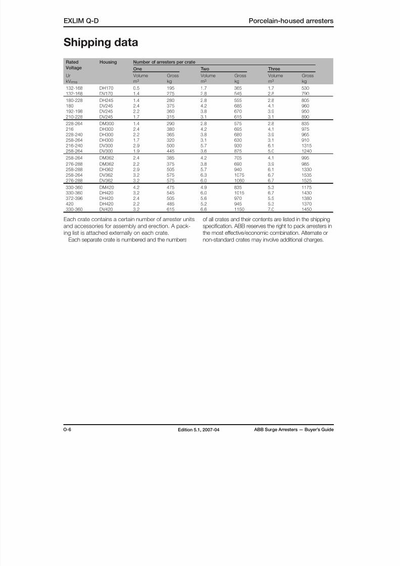
8/10/2019 ABB Extra High Voltage Surge Arresters Up to 420kV
http://slidepdf.com/reader/full/abb-extra-high-voltage-surge-arresters-up-to-420kv 72/96
O-6 ABB Surge Arresters — Buyer’s GuideEdition 5.1, 2007-04
Rated
Voltage
Housing Number of arresters per crate
One Two Three
Ur
kV rms
Volume
m3
Gross
kg
Volume
m3
Gross
kg
Volume
m3
Gross
kg
132-168 DH170 0.5 195 1.7 365 1.7 530
132-168 DV170 1.4 275 2.8 545 2.8 790
180-228 DH245 1.4 280 2.8 555 2.8 805
180 DV245 2.4 375 4.2 685 4.1 960
192-198 DV245 2.2 360 3.8 670 3.9 950
210-228 DV245 1.7 315 3.1 615 3.1 890
228-264 DM300 1.4 290 2.8 575 2.8 835
216 DH300 2.4 380 4.2 695 4.1 975
228-240 DH300 2.2 365 3.8 680 3.9 965
258-264 DH300 1.7 320 3.1 630 3.1 910
216-240 DV300 2.9 500 5.7 930 6.1 1315
258-264 DV300 1.9 445 3.6 875 5.0 1240
258-264 DM362 2.4 385 4.2 705 4.1 995
276-288 DM362 2.2 375 3.8 690 3.9 985
258-288 DH362 2.9 505 5.7 940 6.1 1330258-264 DV362 3.2 575 6.3 1075 6.7 1535
276-288 DV362 3.2 575 6.0 1060 6.7 1525
330-360 DM420 4.2 475 4.9 835 5.3 1175
330-360 DH420 3.2 545 6.0 1015 6.7 1430
372-396 DH420 2.4 505 5.6 970 5.5 1380
420 DH420 2.2 485 5.2 945 5.3 1370
330-360 DV420 3.2 615 6.6 1150 7.0 1450
EXLIM Q-D Porcelain-housed arresters
Shipping data
Each crate contains a certain number of arrester units
and accessories for assembly and erection. A pack-
ing list is attached externally on each crate.
Each separate crate is numbered and the numbers
of all crates and their contents are listed in the shipping
specification. ABB reserves the right to pack arresters in
the most effective/economic combination. Alternate or
non-standard crates may involve additional charges.
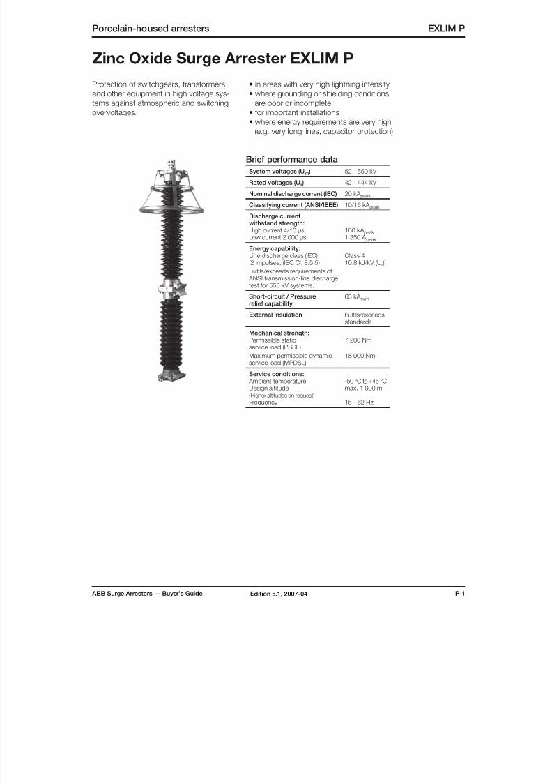
8/10/2019 ABB Extra High Voltage Surge Arresters Up to 420kV
http://slidepdf.com/reader/full/abb-extra-high-voltage-surge-arresters-up-to-420kv 73/96
ABB Surge Arresters — Buyer’s Guide P-1Edition 5.1, 2007-04
Porcelain-housed arresters EXLIM P
Zinc Oxide Surge Arrester EXLIM P
Protection of switchgears, transformers
and other equipment in high voltage sys-
tems against atmospheric and switching
overvoltages.
• in areas with very high lightning intensity
• where grounding or shielding conditions
are poor or incomplete
• for important installations• where energy requirements are very high
(e.g. very long lines, capacitor protection).
Brief performance data
System voltages (Um ) 52 - 550 kV
Rated voltages (Ur ) 42 - 444 kV
Nominal discharge current (IEC) 20 kA peak
Classifying current (ANSI/IEEE) 10/15 kA peak
Discharge currentwithstand strength:
High current 4/10 µsLow current 2 000 µs 100 kA peak 1 350 A peak
Energy capability:Line discharge class (IEC)[2 impulses, (IEC Cl. 8.5.5)
Fulfils/exceeds requirements of ANSI transmission-line dischargetest for 550 kV systems.
Class 410.8 kJ/kV (Ur )]
Short-circuit / Pressurerelief capability
65 kA sym
External insulation Fulfils/exceedsstandards
Mechanical strength:Permissible static
service load (PSSL)Maximum permissible dynamicservice load (MPDSL)
7 200 Nm
18 000 Nm
Service conditions: Ambient temperatureDesign altitude(Higher altitudes on request)
Frequency
-50 °C to +45 °Cmax. 1 000 m
15 - 62 Hz
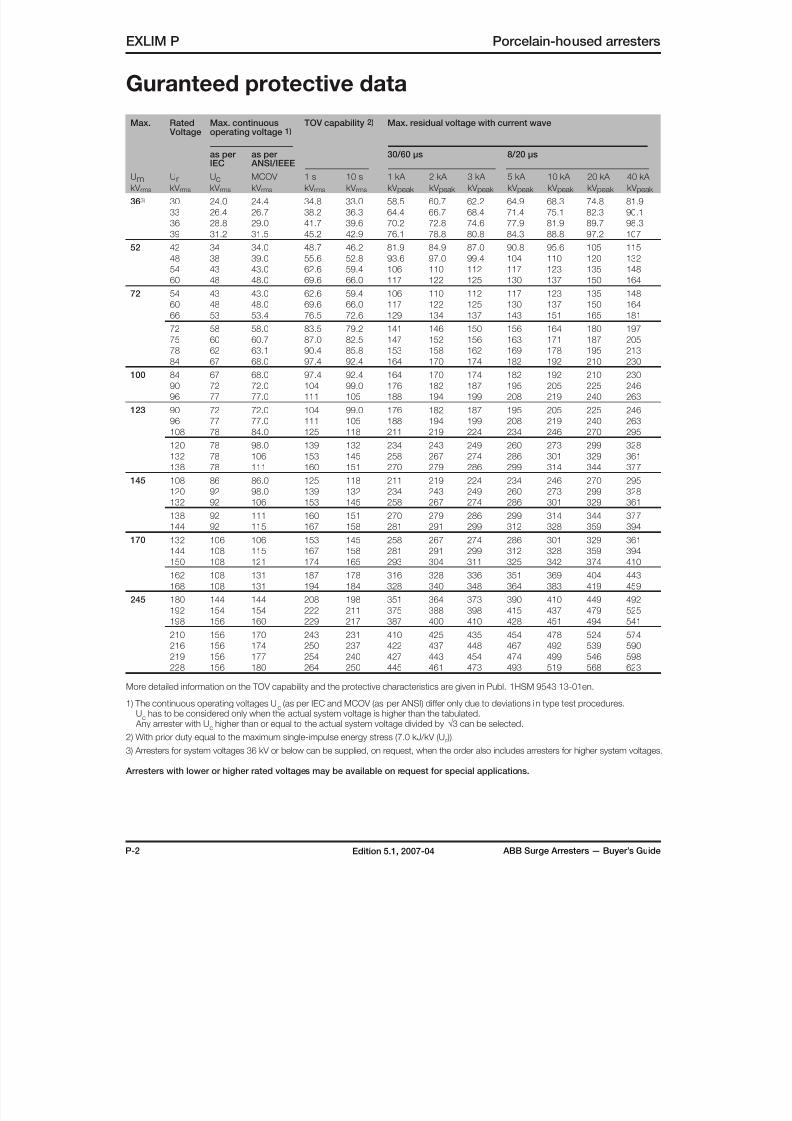
8/10/2019 ABB Extra High Voltage Surge Arresters Up to 420kV
http://slidepdf.com/reader/full/abb-extra-high-voltage-surge-arresters-up-to-420kv 74/96
P-2 ABB Surge Arresters — Buyer’s GuideEdition 5.1, 2007-04
Max. Rated Voltage
Max. continuousoperating voltage 1)
TOV capability 2) Max. residual voltage with current wave
as per
IEC
as per
ANSI/IEEE
30/60 µs 8/20 µs
UmkV rms
UrkV rms
UckV rms
MCOV
kV rms
1 s
kV rms
10 s
kV rms
1 kA
kV peak
2 kA
kV peak
3 kA
kV peak
5 kA
kV peak
10 kA
kV peak
20 kA
kV peak
40 kA
kV peak
363) 30 24.0 24.4 34.8 33.0 58.5 60.7 62.2 64.9 68.3 74.8 81.9
33 26.4 26.7 38.2 36.3 64.4 66.7 68.4 71.4 75.1 82.3 90.1
36 28.8 29.0 41.7 39.6 70.2 72.8 74.6 77.9 81.9 89.7 98.3
39 31.2 31.5 45.2 42.9 76.1 78.8 80.8 84.3 88.8 97.2 107
52 42 34 34.0 48.7 46.2 81.9 84.9 87.0 90.8 95.6 105 115
48 38 39.0 55.6 52.8 93.6 97.0 99.4 104 110 120 132
54 43 43.0 62.6 59.4 106 110 112 117 123 135 148
60 48 48.0 69.6 66.0 117 122 125 130 137 150 164
72 54 43 43.0 62.6 59.4 106 110 112 117 123 135 148
60 48 48.0 69.6 66.0 117 122 125 130 137 150 164
66 53 53.4 76.5 72.6 129 134 137 143 151 165 181
72 58 58.0 83.5 79.2 141 146 150 156 164 180 197
75 60 60.7 87.0 82.5 147 152 156 163 171 187 205
78 62 63.1 90.4 85.8 153 158 162 169 178 195 213
84 67 68.0 97.4 92.4 164 170 174 182 192 210 230
100 84 67 68.0 97.4 92.4 164 170 174 182 192 210 230
90 72 72.0 104 99.0 176 182 187 195 205 225 246
96 77 77.0 111 105 188 194 199 208 219 240 263
123 90 72 72.0 104 99.0 176 182 187 195 205 225 246
96 77 77.0 111 105 188 194 199 208 219 240 263
108 78 84.0 125 118 211 219 224 234 246 270 295
120 78 98.0 139 132 234 243 249 260 273 299 328
132 78 106 153 145 258 267 274 286 301 329 361
138 78 111 160 151 270 279 286 299 314 344 377
145 108 86 86.0 125 118 211 219 224 234 246 270 295
120 92 98.0 139 132 234 243 249 260 273 299 328
132 92 106 153 145 258 267 274 286 301 329 361
138 92 111 160 151 270 279 286 299 314 344 377
144 92 115 167 158 281 291 299 312 328 359 394
170 132 106 106 153 145 258 267 274 286 301 329 361
144 108 115 167 158 281 291 299 312 328 359 394
150 108 121 174 165 293 304 311 325 342 374 410
162 108 131 187 178 316 328 336 351 369 404 443
168 108 131 194 184 328 340 348 364 383 419 459
245 180 144 144 208 198 351 364 373 390 410 449 492
192 154 154 222 211 375 388 398 415 437 479 525
198 156 160 229 217 387 400 410 428 451 494 541
210 156 170 243 231 410 425 435 454 478 524 574
216 156 174 250 237 422 437 448 467 492 539 590
219 156 177 254 240 427 443 454 474 499 546 598
228 156 180 264 250 445 461 473 493 519 568 623
More detailed information on the TOV capability and the protective characteristics are given in Publ. 1HSM 9543 13-01en.
1) The continuous operating voltages Uc
(as per IEC and MCOV (as per ANSI) differ only due to deviations in type test procedures. U
c has to be considered only when the actual system voltage is higher than the tabulated.
Any arrester with Uc higher than or equal to the actual system voltage divided by √3 can be selected.
2) With prior duty equal to the maximum single-impulse energy stress (7.0 kJ/kV (Ur )).
3) Arresters for system voltages 36 kV or below can be supplied, on request, when the order also includes arresters for higher system voltages.
Arresters with lower or higher rated voltages may be available on request for special applications.
EXLIM P Porcelain-housed arresters
Guranteed protective data
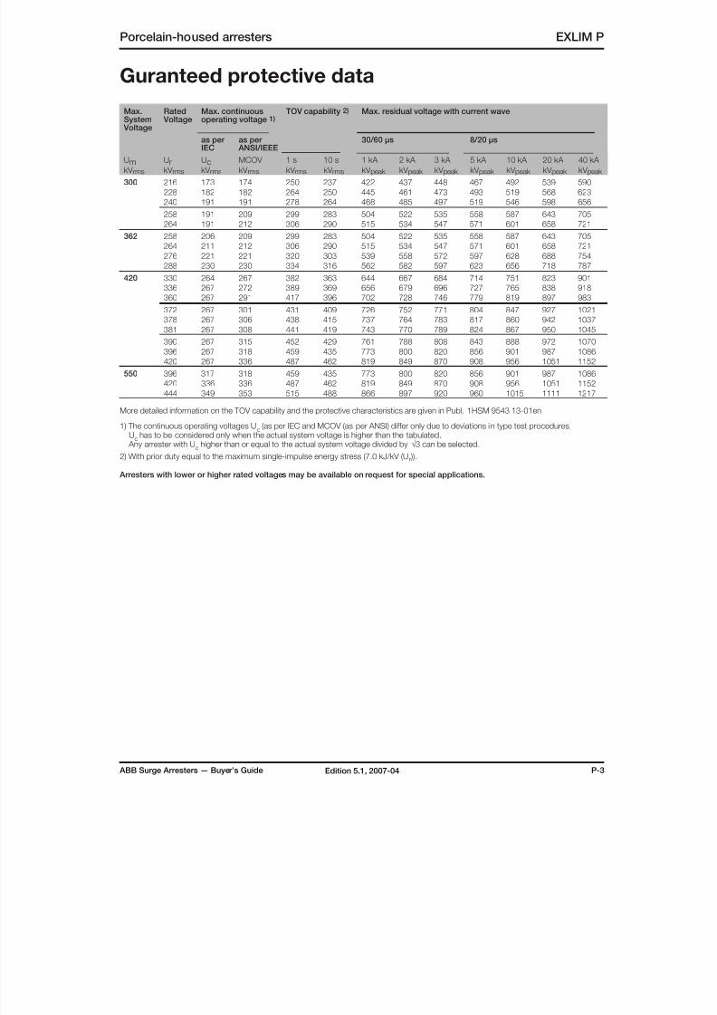
8/10/2019 ABB Extra High Voltage Surge Arresters Up to 420kV
http://slidepdf.com/reader/full/abb-extra-high-voltage-surge-arresters-up-to-420kv 75/96
ABB Surge Arresters — Buyer’s Guide P-3Edition 5.1, 2007-04
Porcelain-housed arresters EXLIM P
Guranteed protective data
Max.System
Voltage
Rated Voltage
Max. continuousoperating voltage 1)
TOV capability 2) Max. residual voltage with current wave
as per
IEC
as per
ANSI/IEEE
30/60 µs 8/20 µs
UmkV rms
UrkV rms
UckV rms
MCOV
kV rms
1 s
kV rms
10 s
kV rms
1 kA
kV peak
2 kA
kV peak
3 kA
kV peak
5 kA
kV peak
10 kA
kV peak
20 kA
kV peak
40 kA
kV peak
300 216 173 174 250 237 422 437 448 467 492 539 590
228 182 182 264 250 445 461 473 493 519 568 623
240 191 191 278 264 468 485 497 519 546 598 656
258 191 209 299 283 504 522 535 558 587 643 705
264 191 212 306 290 515 534 547 571 601 658 721
362 258 206 209 299 283 504 522 535 558 587 643 705
264 211 212 306 290 515 534 547 571 601 658 721
276 221 221 320 303 539 558 572 597 628 688 754
288 230 230 334 316 562 582 597 623 656 718 787
420 330 264 267 382 363 644 667 684 714 751 823 901
336 267 272 389 369 656 679 696 727 765 838 918
360 267 291 417 396 702 728 746 779 819 897 983
372 267 301 431 409 726 752 771 804 847 927 1021
378 267 306 438 415 737 764 783 817 860 942 1037
381 267 308 441 419 743 770 789 824 867 950 1045
390 267 315 452 429 761 788 808 843 888 972 1070
396 267 318 459 435 773 800 820 856 901 987 1086
420 267 336 487 462 819 849 870 908 956 1051 1152
550 396 317 318 459 435 773 800 820 856 901 987 1086
420 336 336 487 462 819 849 870 908 956 1051 1152
444 349 353 515 488 866 897 920 960 1015 1111 1217
More detailed information on the TOV capability and the protective characteristics are given in Publ. 1HSM 9543 13-01en
1) The continuous operating voltages Uc
(as per IEC and MCOV (as per ANSI) differ only due to deviations in type test procedures. U
c has to be considered only when the actual system voltage is higher than the tabulated.
Any arrester with Uc higher than or equal to the actual system voltage divided by √3 can be selected.
2) With prior duty equal to the maximum single-impulse energy stress (7.0 kJ/kV (Ur )).
Arresters with lower or higher rated voltages may be available on request for special applications.
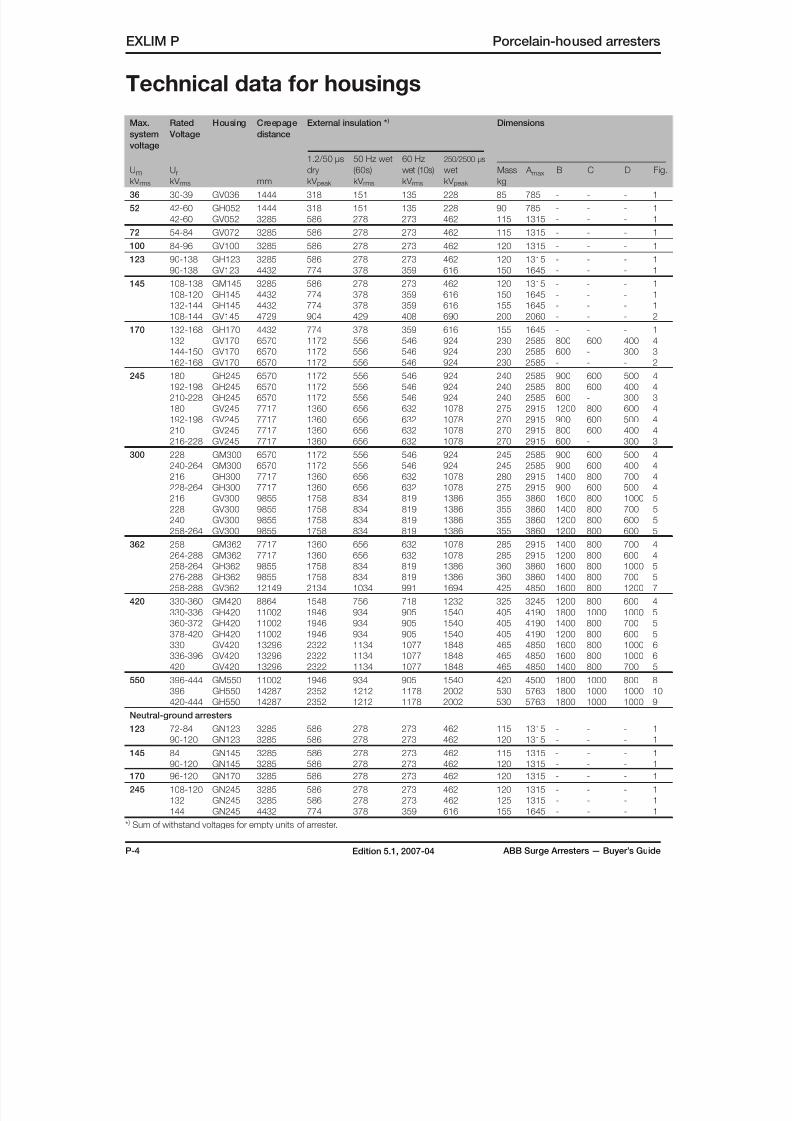
8/10/2019 ABB Extra High Voltage Surge Arresters Up to 420kV
http://slidepdf.com/reader/full/abb-extra-high-voltage-surge-arresters-up-to-420kv 76/96
P-4 ABB Surge Arresters — Buyer’s GuideEdition 5.1, 2007-04
Max.
system
voltage
Rated
Voltage
Housing Creepage
distance
External insulation * ) Dimensions
UmkV rms
UrkV rms mm
1.2/50 µs
dry
kV peak
50 Hz wet
(60s)
kV rms
60 Hz
wet (10s)
kV rms
250/2500 µs
wet
kV peak
Mass
kg
A max B C D Fig.
36 30-39 GV036 1444 318 151 135 228 85 785 - - - 1
52 42-60 GH052 1444 318 151 135 228 90 785 - - - 1
42-60 GV052 3285 586 278 273 462 115 1315 - - - 1
72 54-84 GV072 3285 586 278 273 462 115 1315 - - - 1
100 84-96 GV100 3285 586 278 273 462 120 1315 - - - 1
123 90-138 GH123 3285 586 278 273 462 120 1315 - - - 1
90-138 GV123 4432 774 378 359 616 150 1645 - - - 1
145 108-138 GM145 3285 586 278 273 462 120 1315 - - - 1
108-120 GH145 4432 774 378 359 616 150 1645 - - - 1
132-144 GH145 4432 774 378 359 616 155 1645 - - - 1
108-144 GV145 4729 904 429 408 690 200 2060 - - - 2
170 132-168 GH170 4432 774 378 359 616 155 1645 - - - 1132 GV170 6570 1172 556 546 924 230 2585 800 600 400 4
144-150 GV170 6570 1172 556 546 924 230 2585 600 - 300 3
162-168 GV170 6570 1172 556 546 924 230 2585 - - - 2
245 180 GH245 6570 1172 556 546 924 240 2585 900 600 500 4
192-198 GH245 6570 1172 556 546 924 240 2585 800 600 400 4
210-228 GH245 6570 1172 556 546 924 240 2585 600 - 300 3
180 GV245 7717 1360 656 632 1078 275 2915 1200 800 600 4
192-198 GV245 7717 1360 656 632 1078 270 2915 900 600 500 4
210 GV245 7717 1360 656 632 1078 270 2915 800 600 400 4
216-228 GV245 7717 1360 656 632 1078 270 2915 600 - 300 3
300 228 GM300 6570 1172 556 546 924 245 2585 900 600 500 4
240-264 GM300 6570 1172 556 546 924 245 2585 900 600 400 4
216 GH300 7717 1360 656 632 1078 280 2915 1400 800 700 4
228-264 GH300 7717 1360 656 632 1078 275 2915 900 600 500 4
216 GV300 9855 1758 834 819 1386 355 3860 1600 800 1000 5228 GV300 9855 1758 834 819 1386 355 3860 1400 800 700 5
240 GV300 9855 1758 834 819 1386 355 3860 1200 800 600 5
258-264 GV300 9855 1758 834 819 1386 355 3860 1200 800 600 5
362 258 GM362 7717 1360 656 632 1078 285 2915 1400 800 700 4
264-288 GM362 7717 1360 656 632 1078 285 2915 1200 800 600 4
258-264 GH362 9855 1758 834 819 1386 360 3860 1600 800 1000 5
276-288 GH362 9855 1758 834 819 1386 360 3860 1400 800 700 5
258-288 GV362 12149 2134 1034 991 1694 425 4850 1600 800 1200 7
420 330-360 GM420 8864 1548 756 718 1232 325 3245 1200 800 600 4
330-336 GH420 11002 1946 934 905 1540 405 4190 1800 1000 1000 5
360-372 GH420 11002 1946 934 905 1540 405 4190 1400 800 700 5
378-420 GH420 11002 1946 934 905 1540 405 4190 1200 800 600 5
330 GV420 13296 2322 1134 1077 1848 465 4850 1600 800 1000 6
336-396 GV420 13296 2322 1134 1077 1848 465 4850 1600 800 1000 6
420 GV420 13296 2322 1134 1077 1848 465 4850 1400 800 700 5550 396-444 GM550 11002 1946 934 905 1540 420 4500 1800 1000 800 8
396 GH550 14287 2352 1212 1178 2002 530 5763 1800 1000 1000 10
420-444 GH550 14287 2352 1212 1178 2002 530 5763 1800 1000 1000 9
Neutral-ground arresters
123 72-84 GN123 3285 586 278 273 462 115 1315 - - - 1
90-120 GN123 3285 586 278 273 462 120 1315 - - - 1
145 84 GN145 3285 586 278 273 462 115 1315 - - - 1
90-120 GN145 3285 586 278 273 462 120 1315 - - - 1
170 96-120 GN170 3285 586 278 273 462 120 1315 - - - 1
245 108-120 GN245 3285 586 278 273 462 120 1315 - - - 1
132 GN245 3285 586 278 273 462 125 1315 - - - 1
144 GN245 4432 774 378 359 616 155 1645 - - - 1
* ) Sum of withstand voltages for empty units of arrester.
EXLIM P Porcelain-housed arresters
Technical data for housings
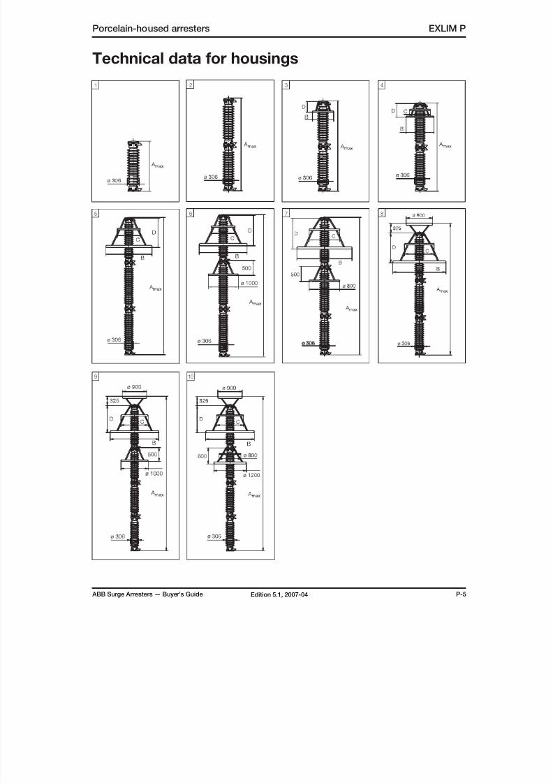
8/10/2019 ABB Extra High Voltage Surge Arresters Up to 420kV
http://slidepdf.com/reader/full/abb-extra-high-voltage-surge-arresters-up-to-420kv 77/96
ABB Surge Arresters — Buyer’s Guide P-5Edition 5.1, 2007-04
Porcelain-housed arresters EXLIM P
Technical data for housings
41 2 3
85 6 7
9 10
ø 306

8/10/2019 ABB Extra High Voltage Surge Arresters Up to 420kV
http://slidepdf.com/reader/full/abb-extra-high-voltage-surge-arresters-up-to-420kv 78/96
P-6 ABB Surge Arresters — Buyer’s GuideEdition 5.1, 2007-04
EXLIM P Porcelain-housed arresters
Accessories
1HSA410 000-A Aluminium
1HSA410 000-B Aluminium flag with other
items in stainless steel
1HSA410 000-C Aluminium
1HSA420 000-CStainless steel
1HSA420 000-DStainless steel
1HSA430 000-CEpoxy resin
With insulating base
Without insulating base
1HSA410 000-DStainless steel
Line terminals Earth terminals
M16 bolts for connection to structure are notsupplied by ABB. Required threaded griplength is 15-20 mm.
Drilling plans
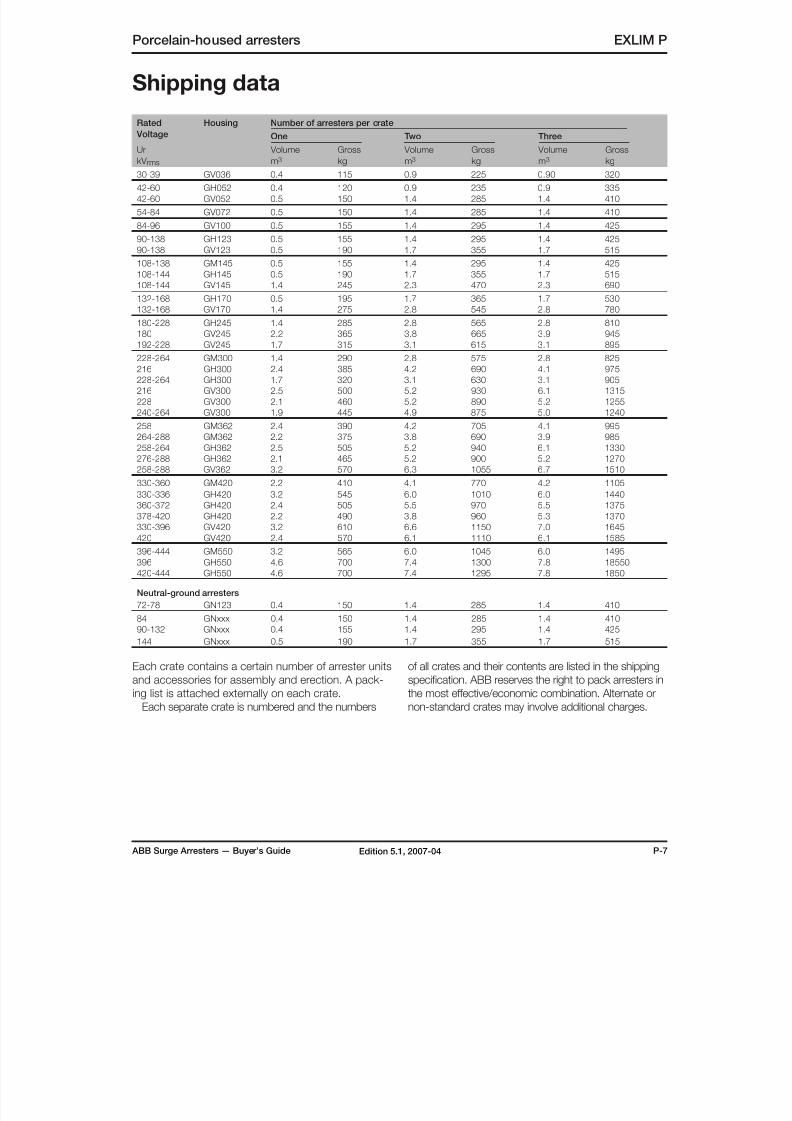
8/10/2019 ABB Extra High Voltage Surge Arresters Up to 420kV
http://slidepdf.com/reader/full/abb-extra-high-voltage-surge-arresters-up-to-420kv 79/96
ABB Surge Arresters — Buyer’s Guide P-7Edition 5.1, 2007-04
Porcelain-housed arresters EXLIM P
Shipping data
Rated
Voltage
Housing Number of arresters per crate
One Two Three
Ur
kV rms
Volume
m3
Gross
kg
Volume
m3
Gross
kg
Volume
m3
Gross
kg
30-39 GV036 0.4 115 0.9 225 0.90 320
42-60 GH052 0.4 120 0.9 235 0.9 335
42-60 GV052 0.5 150 1.4 285 1.4 410
54-84 GV072 0.5 150 1.4 285 1.4 410
84-96 GV100 0.5 155 1.4 295 1.4 425
90-138 GH123 0.5 155 1.4 295 1.4 425
90-138 GV123 0.5 190 1.7 355 1.7 515
108-138 GM145 0.5 155 1.4 295 1.4 425
108-144 GH145 0.5 190 1.7 355 1.7 515
108-144 GV145 1.4 245 2.3 470 2.3 690
132-168 GH170 0.5 195 1.7 365 1.7 530
132-168 GV170 1.4 275 2.8 545 2.8 780
180-228 GH245 1.4 285 2.8 565 2.8 810
180 GV245 2.2 365 3.8 665 3.9 945192-228 GV245 1.7 315 3.1 615 3.1 895
228-264 GM300 1.4 290 2.8 575 2.8 825
216 GH300 2.4 385 4.2 690 4.1 975
228-264 GH300 1.7 320 3.1 630 3.1 905
216 GV300 2.5 500 5.2 930 6.1 1315
228 GV300 2.1 460 5.2 890 5.2 1255
240-264 GV300 1.9 445 4.9 875 5.0 1240
258 GM362 2.4 390 4.2 705 4.1 995
264-288 GM362 2.2 375 3.8 690 3.9 985
258-264 GH362 2.5 505 5.2 940 6.1 1330
276-288 GH362 2.1 465 5.2 900 5.2 1270
258-288 GV362 3.2 570 6.3 1055 6.7 1510
330-360 GM420 2.2 410 4.1 770 4.2 1105
330-336 GH420 3.2 545 6.0 1010 6.0 1440
360-372 GH420 2.4 505 5.5 970 5.5 1375
378-420 GH420 2.2 490 3.8 960 5.3 1370
330-396 GV420 3.2 610 6.6 1150 7.0 1645
420 GV420 2.4 570 6.1 1110 6.1 1585
396-444 GM550 3.2 565 6.0 1045 6.0 1495
396 GH550 4.6 700 7.4 1300 7.8 18550
420-444 GH550 4.6 700 7.4 1295 7.8 1850
Neutral-ground arresters
72-78 GN123 0.4 150 1.4 285 1.4 410
84 GNxxx 0.4 150 1.4 285 1.4 410
90-132 GNxxx 0.4 155 1.4 295 1.4 425
144 GNxxx 0.5 190 1.7 355 1.7 515
Each crate contains a certain number of arrester unitsand accessories for assembly and erection. A pack-
ing list is attached externally on each crate.
Each separate crate is numbered and the numbers
of all crates and their contents are listed in the shippingspecification. ABB reserves the right to pack arresters in
the most effective/economic combination. Alternate or
non-standard crates may involve additional charges.
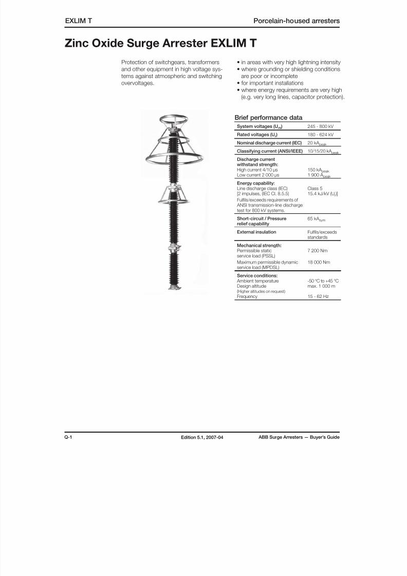
8/10/2019 ABB Extra High Voltage Surge Arresters Up to 420kV
http://slidepdf.com/reader/full/abb-extra-high-voltage-surge-arresters-up-to-420kv 80/96
Q-1 ABB Surge Arresters — Buyer’s GuideEdition 5.1, 2007-04
EXLIM T Porcelain-housed arresters
Zinc Oxide Surge Arrester EXLIM T
Protection of switchgears, transformers
and other equipment in high voltage sys-
tems against atmospheric and switching
overvoltages.
• in areas with very high lightning intensity
• where grounding or shielding conditions
are poor or incomplete
• for important installations• where energy requirements are very high
(e.g. very long lines, capacitor protection).
Brief performance data
System voltages (Um ) 245 - 800 kV
Rated voltages (Ur ) 180 - 624 kV
Nominal discharge current (IEC) 20 kA peak
Classifying current (ANSI/IEEE) 10/15/20 kA peak
Discharge currentwithstand strength:
High current 4/10 µsLow current 2 000 µs 150 kA peak 1 900 A peak
Energy capability:Line discharge class (IEC)[2 impulses, (IEC Cl. 8.5.5)
Fulfils/exceeds requirements of ANSI transmission-line dischargetest for 800 kV systems.
Class 515.4 kJ/kV (Ur )]
Short-circuit / Pressurerelief capability
65 kA sym
External insulation Fulfils/exceedsstandards
Mechanical strength:Permissible static
service load (PSSL)Maximum permissible dynamicservice load (MPDSL)
7 200 Nm
18 000 Nm
Service conditions: Ambient temperatureDesign altitude(Higher altitudes on request)
Frequency
-50 °C to +45 °Cmax. 1 000 m
15 - 62 Hz

8/10/2019 ABB Extra High Voltage Surge Arresters Up to 420kV
http://slidepdf.com/reader/full/abb-extra-high-voltage-surge-arresters-up-to-420kv 81/96
ABB Surge Arresters — Buyer’s Guide Q-2Edition 5.1, 2007-04
Porcelain-housed arresters EXLIM T
Max. Rated Voltage
Max. continuousoperating voltage 1)
TOV capability 2) Max. residual voltage with current wave
as per
IEC
as per
ANSI/IEEE
30/60 µs 8/20 µs
UmkV rms
UrkV rms
UckV rms
MCOV
kV rms
1 s
kV rms
10 s
kV rms
1 kA
kV peak
2 kA
kV peak
3 kA
kV peak
5 kA
kV peak
10 kA
kV peak
20 kA
kV peak
40 kA
kV peak
245 180 144 144 205 194 346 356 363 381 396 428 466
192 154 154 218 207 369 380 387 406 423 457 497
198 156 160 225 213 381 392 399 419 436 471 512
210 156 170 239 226 404 415 423 444 462 499 543
216 156 174 246 233 415 427 435 457 476 514 559
219 156 177 249 236 421 433 441 463 482 521 567
228 156 180 259 246 438 451 459 482 502 542 590
300 216 173 174 246 233 415 427 435 457 476 514 559
228 182 182 259 246 438 451 459 482 502 542 590
240 191 191 273 259 461 475 484 507 528 571 621
258 191 209 294 278 496 510 520 545 568 614 667
264 191 212 300 285 508 522 532 558 581 628 683
362 258 206 209 294 278 496 510 520 545 568 614 667
264 211 212 300 285 508 522 532 558 581 628 683
276 221 221 314 298 531 546 556 583 608 656 714
288 230 230 328 311 554 569 580 609 634 685 745
420 330 264 267 376 356 634 652 665 697 726 785 854
336 267 272 383 362 646 664 677 710 740 799 869
360 267 291 410 388 692 712 725 761 792 856 931
372 267 301 424 401 715 735 749 786 819 884 962
378 267 306 430 408 726 747 761 799 832 899 978
381 267 308 434 411 732 753 767 805 839 906 985
390 267 315 444 421 750 771 786 824 858 927 1013
396 267 318 451 427 761 783 798 837 872 941 1029
420 267 336 478 453 807 830 846 888 924 998 1091
550 396 317 318 451 427 761 783 798 837 872 941 1029
420 336 336 478 453 807 830 846 888 924 998 1091
444 349 353 506 479 853 878 894 938 977 1060 1153
800 588 470 470 670 635 1134 1167 1189 1247 1299 1402 1525
612 490 490 697 660 1180 1214 1237 1298 1351 1459 1587
624 499 499 711 673 1203 1238 1261 1323 1378 1488 1618
More detailed information on the TOV capability and the protective characteristics are given in Publ. 1HSM 9543 13-01en.
1) The continuous operating voltages Uc (as per IEC and MCOV (as per ANSI) differ only due to deviations in type test procedures.
Uc has to be considered only when the actual system voltage is higher than the tabulated. Any arrester with U
c higher than or equal to the actual system voltage divided by √3 can be selected.
2) With prior duty equal to the maximum single-impulse energy stress (10.0 kJ/kV (Ur )).
Arresters with lower or higher rated voltages may be available on request for special applications.
Guranteed protective data
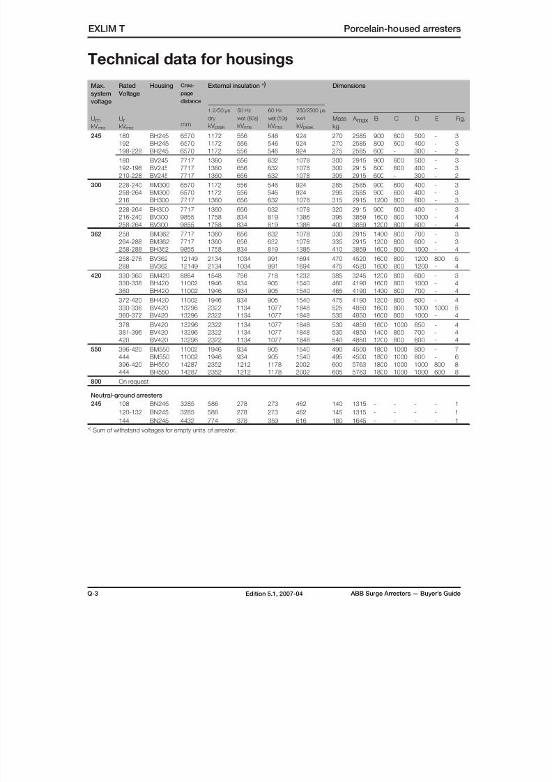
8/10/2019 ABB Extra High Voltage Surge Arresters Up to 420kV
http://slidepdf.com/reader/full/abb-extra-high-voltage-surge-arresters-up-to-420kv 82/96

8/10/2019 ABB Extra High Voltage Surge Arresters Up to 420kV
http://slidepdf.com/reader/full/abb-extra-high-voltage-surge-arresters-up-to-420kv 83/96
ABB Surge Arresters — Buyer’s Guide Q-4Edition 5.1, 2007-04
Porcelain-housed arresters EXLIM T
Technical data for housings
41 2 3
5 6 7
ø 306
8

8/10/2019 ABB Extra High Voltage Surge Arresters Up to 420kV
http://slidepdf.com/reader/full/abb-extra-high-voltage-surge-arresters-up-to-420kv 84/96
Q-5 ABB Surge Arresters — Buyer’s GuideEdition 5.1, 2007-04
Accessories
1HSA410 000-A Aluminium
1HSA410 000-B Aluminium flag with other
items in stainless steel
1HSA410 000-C Aluminium
1HSA420 000-CStainless steel
1HSA420 000-DStainless steel
1HSA430 000-CEpoxy resin
With insulating base
Without insulating base
1HSA410 000-DStainless steel
Line terminals Earth terminals
M16 bolts for connection to structure are notsupplied by ABB. Required threaded griplength is 15-20 mm.
Drilling plans
EXLIM T Porcelain-housed arresters
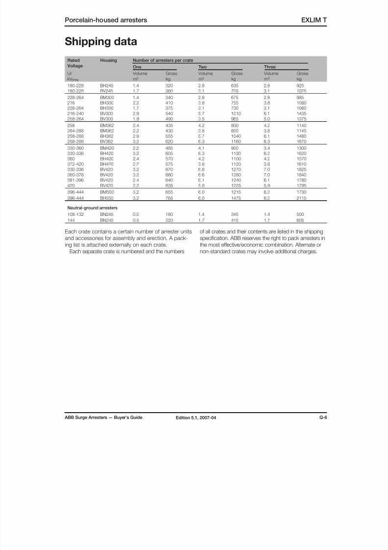
8/10/2019 ABB Extra High Voltage Surge Arresters Up to 420kV
http://slidepdf.com/reader/full/abb-extra-high-voltage-surge-arresters-up-to-420kv 85/96
ABB Surge Arresters — Buyer’s Guide Q-6Edition 5.1, 2007-04
Porcelain-housed arresters EXLIM T
Rated
Voltage
Housing Number of arresters per crate
One Two Three
Ur
kV rms
Volume
m3
Gross
kg
Volume
m3
Gross
kg
Volume
m3
Gross
kg
180-228 BH245 1.4 320 2.8 635 2.8 925
180-228 BV245 1.7 360 3.1 705 3.1 1025
228-264 BM300 1.4 340 2.8 675 2.8 985
216 BH300 2.2 410 3.8 755 3.8 1080
228-264 BH300 1.7 375 3.1 730 3.1 1060
216-240 BV300 2.9 540 5.7 1010 6.1 1435
258-264 BV300 1.9 490 3.5 965 5.0 1375
258 BM362 2.4 435 4.2 800 4.2 1140
264-288 BM362 2.2 430 3.8 800 3.8 1145
258-288 BH362 2.9 555 5.7 1040 6.1 1480
258-288 BV362 3.2 620 6.3 1160 6.3 1670
330-360 BM420 2.2 485 4.1 900 3.4 1300
330-336 BH420 3.2 605 6.3 1130 6.3 1620
360 BH420 2.4 570 4.2 1100 4.2 1570
372-420 BH420 2.2 575 3.8 1120 3.8 1610330-336 BV420 3.2 670 6.6 1270 7.0 1825
360-378 BV420 3.2 680 6.6 1280 7.0 1840
381-396 BV420 2.4 640 6.1 1240 6.1 1780
420 BV420 2.2 635 5.8 1225 5.9 1795
396-444 BM550 3.2 655 6.0 1215 6.3 1730
396-444 BH550 3.2 765 6.0 1475 6.3 2115
Neutral-ground arresters
108-132 BN245 0.5 180 1.4 345 1.4 500
144 BN245 0.5 220 1.7 415 1.7 605
Shipping data
Each crate contains a certain number of arrester units
and accessories for assembly and erection. A pack-
ing list is attached externally on each crate.Each separate crate is numbered and the numbers
of all crates and their contents are listed in the shipping
specification. ABB reserves the right to pack arresters in
the most effective/economic combination. Alternate ornon-standard crates may involve additional charges.

8/10/2019 ABB Extra High Voltage Surge Arresters Up to 420kV
http://slidepdf.com/reader/full/abb-extra-high-voltage-surge-arresters-up-to-420kv 86/96
R-1 ABB Surge Arresters — Buyer’s GuideEdition 5.1, 2007-04
EXCOUNT-II Accessories
Surge Arrester Monitor EXCOUNT-II
As businesses strive to remain compe-
titive, improved reliability of electricity
supply and reduced maintenance costs
are demanded by both power utilitiesand users alike.
ABB has in response developed
EXCOUNT-II; an advanced surge arres-
ter monitor for effectively, reliably and
safely monitoring and recording surges
on high voltage electrical
networks.
More than just a counter Discharge operation counters have been
available for use with surge arresters for
many years, however these have lacked
the ability of giving a direct indication ofthe true health of surge arresters. Even
counters fitted with simple mA meters
are of very limited use, as they are unable
to differentiate between the internal and
external leakage currents nor exclude
harmonic effects.
EXCOUNT-II is an entirely new
monitoring system, as it can be used as
an aid to assess the health of the entire
substation by monitoring surges trans-
mitted in and out of the network. The
device is fitted to surge arresters withina substation similar to normal counters,
but in addition to counting the number
of discharges, EXCOUNT-II also records
the amplitude of the surges, together with
their date and time, plus measures the
total leakage current and (optionally) resis-
tive current through the arrester.
The measurements are stored in the
EXCOUNT-II sensor, and can be collected
when convenient with the aid of a hand-
held cordless transceiver. The raw data
is then transferred over to a computer for
statistical analysis.
The detailed results obtained from
EXCOUNT-II are not limited to a simple
estimation of arrester stresses but instead
give a true indication of the number and
severity of surges and, when combined
with data from event recorders, SCADA,
etc, facilitiates an effective analysis of theamount and degree of voltage stress all
equipment in the substation have been
subjected to.
Unique data acquisition methodEXCOUNT-II is unique in its method of
acquiring data. Each surge arrester is
fitted with a sensor, which detects the
total number of discharges, the surge
amplitude, date and time of occurrence,
as well as the leakage current through the
arrester. All data is stored in the sensor’smemory, and can then be read when
convenient with the aid of a hand-held
transceiver.
EXCOUNT-II´s mea-
surement method is
unique and simple.
The sensor´s measu-
red data is cordlessly
transferred to a hand
held transceiver. The
measured data from
the transceiver can
then be transfered
to a computer for
statistical analysis.
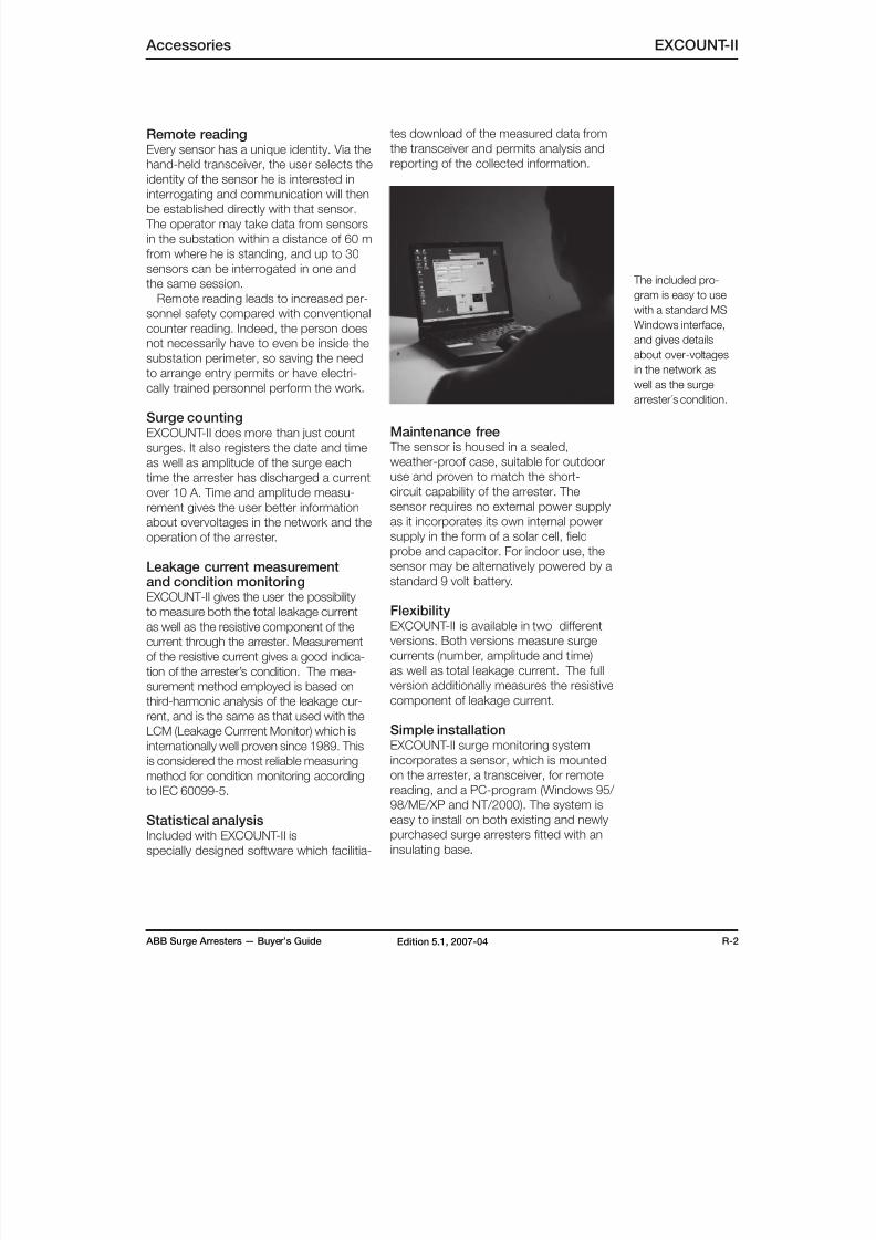
8/10/2019 ABB Extra High Voltage Surge Arresters Up to 420kV
http://slidepdf.com/reader/full/abb-extra-high-voltage-surge-arresters-up-to-420kv 87/96
ABB Surge Arresters — Buyer’s Guide R-2Edition 5.1, 2007-04
Accessories EXCOUNT-II
Remote readingEvery sensor has a unique identity. Via the
hand-held transceiver, the user selects the
identity of the sensor he is interested ininterrogating and communication will then
be established directly with that sensor.
The operator may take data from sensors
in the substation within a distance of 60 m
from where he is standing, and up to 30
sensors can be interrogated in one and
the same session.
Remote reading leads to increased per-
sonnel safety compared with conventional
counter reading. Indeed, the person does
not necessarily have to even be inside the
substation perimeter, so saving the need
to arrange entry permits or have electri-cally trained personnel perform the work.
Surge countingEXCOUNT-II does more than just count
surges. It also registers the date and time
as well as amplitude of the surge each
time the arrester has discharged a current
over 10 A. Time and amplitude measu-
rement gives the user better information
about overvoltages in the network and the
operation of the arrester.
Leakage current measurementand condition monitoringEXCOUNT-II gives the user the possibility
to measure both the total leakage current
as well as the resistive component of the
current through the arrester. Measurement
of the resistive current gives a good indica-
tion of the arrester’s condition. The mea-
surement method employed is based on
third-harmonic analysis of the leakage cur-
rent, and is the same as that used with the
LCM (Leakage Currrent Monitor) which is
internationally well proven since 1989. This
is considered the most reliable measuring
method for condition monitoring according
to IEC 60099-5.
Statistical analysisIncluded with EXCOUNT-II is
specially designed software which facilitia-
tes download of the measured data from
the transceiver and permits analysis and
reporting of the collected information.
Maintenance free The sensor is housed in a sealed,
weather-proof case, suitable for outdoor
use and proven to match the short-
circuit capability of the arrester. The
sensor requires no external power supply
as it incorporates its own internal power
supply in the form of a solar cell, field
probe and capacitor. For indoor use, thesensor may be alternatively powered by a
standard 9 volt battery.
FlexibilityEXCOUNT-II is available in two different
versions. Both versions measure surge
currents (number, amplitude and time)
as well as total leakage current. The full
version additionally measures the resistive
component of leakage current.
Simple installationEXCOUNT-II surge monitoring system
incorporates a sensor, which is mounted
on the arrester, a transceiver, for remote
reading, and a PC-program (Windows 95/
98/ME/XP and NT/2000). The system is
easy to install on both existing and newly
purchased surge arresters fitted with an
insulating base.
The included pro-
gram is easy to use
with a standard MS
Windows interface,
and gives details
about over-voltages
in the network aswell as the surge
arrester´s condition.
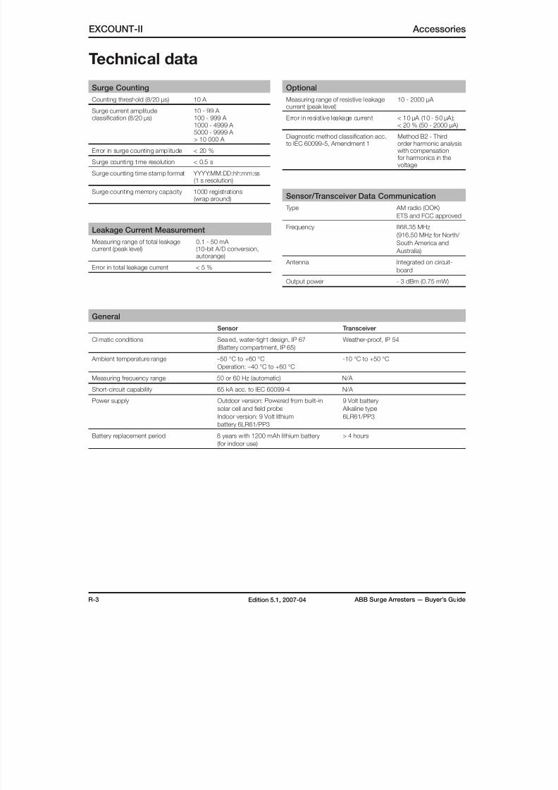
8/10/2019 ABB Extra High Voltage Surge Arresters Up to 420kV
http://slidepdf.com/reader/full/abb-extra-high-voltage-surge-arresters-up-to-420kv 88/96
R-3 ABB Surge Arresters — Buyer’s GuideEdition 5.1, 2007-04
Optional
Measuring range of resistive leakagecurrent (peak level)
10 - 2000 µA
Error in resist ive leakage current < 10 µA (10 - 50 µA);< 20 % (50 - 2000 µA)
Diagnostic method classification acc.to IEC 60099-5, Amendment 1
Method B2 - Thirdorder harmonic analysiswith compensationfor harmonics in thevoltage
Sensor/Transceiver Data Communication
Type AM radio (OOK)
ETS and FCC approved
Frequency 868.35 MHz
(916.50 MHz for North/ South America and
Australia)
Antenna Integrated on circuit-
board
Output power - 3 dBm (0.75 mW)
EXCOUNT-II Accessories
Technical data
Surge Counting
Counting threshold (8/20 µs) 10 A
Surge current amplitude
classification (8/20 µs)
10 - 99 A
100 - 999 A 1000 - 4999 A 5000 - 9999 A > 10 000 A
Error in surge counting amplitude < 20 %
Surge counting time resolution < 0.5 s
Surge counting time stamp format YYYY:MM:DD:hh:mm:ss(1 s resolution)
Surge counting memory capacity 1000 registrations(wrap around)
Leakage Current Measurement
Measuring range of total leakagecurrent (peak level)
0.1 - 50 mA (10-bit A/D conversion,autorange)
Error in total leakage current < 5 %
General
Sensor Transceiver
Climatic conditions Sealed, water-tight design, IP 67
(Battery compartment, IP 65)
Weather-proof, IP 54
Ambient temperature range –50 °C to +60 °C
Operation: –40 °C to +60 °C
-10 °C to +50 °C
Measuring frequency range 50 or 60 Hz (automatic) N/A
Short-circuit capability 65 kA acc. to IEC 60099-4 N/A
Power supply Outdoor version: Powered from built-in
solar cell and field probe
Indoor version: 9 Volt lithium
battery 6LR61/PP3
9 Volt battery
Alkaline type
6LR61/PP3
Battery replacement period 8 years with 1200 mAh lithium battery
(for indoor use)
> 4 hours
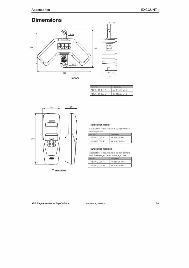
8/10/2019 ABB Extra High Voltage Surge Arresters Up to 420kV
http://slidepdf.com/reader/full/abb-extra-high-voltage-surge-arresters-up-to-420kv 89/96
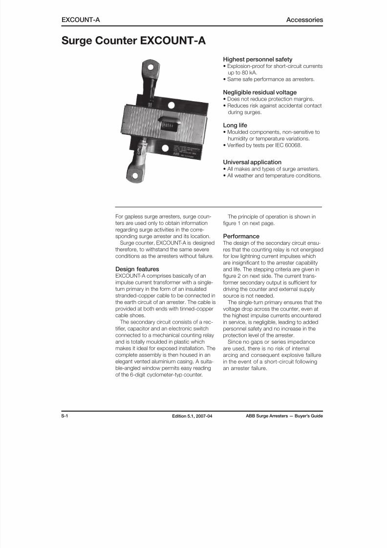
8/10/2019 ABB Extra High Voltage Surge Arresters Up to 420kV
http://slidepdf.com/reader/full/abb-extra-high-voltage-surge-arresters-up-to-420kv 90/96
S-1 ABB Surge Arresters — Buyer’s GuideEdition 5.1, 2007-04
EXCOUNT-A Accessories
Surge Counter EXCOUNT-A
For gapless surge arresters, surge coun-
ters are used only to obtain information
regarding surge activities in the corre-
sponding surge arrester and its location.
Surge counter, EXCOUNT-A is designedtherefore, to withstand the same severe
conditions as the arresters without failure.
Design featuresEXCOUNT-A comprises basically of an
impulse current transformer with a single-
turn primary in the form of an insulated
stranded-copper cable to be connected in
the earth circuit of an arrester. The cable is
provided at both ends with tinned-copper
cable shoes.
The secondary circuit consists of a rec-
tifier, capacitor and an electronic switch
connected to a mechanical counting relay
and is totally moulded in plastic which
makes it ideal for exposed installation. The
complete assembly is then housed in an
elegant vented aluminium casing. A suita-
ble-angled window permits easy reading
of the 6-digit cyclometer-typ counter.
Highest personnel safety• Explosion-proof for short-circuit currents
up to 80 kA.
• Same safe performance as arresters.
Negligible residual voltage• Does not reduce protection margins.
• Reduces risk against accidental contact
during surges.
Long life• Moulded components, non-sensitive to
humidity or temperature variations.
• Verified by tests per IEC 60068.
Universal application• All makes and types of surge arresters.
• All weather and temperature conditions.
The principle of operation is shown in
figure 1 on next page.
Performance
The design of the secondary circuit ensu-res that the counting relay is not energised
for low lightning current impulses which
are insignificant to the arrester capability
and life. The stepping criteria are given in
figure 2 on next side. The current trans-
former secondary output is sufficient for
driving the counter and external supply
source is not needed.
The single-turn primary ensures that the
voltage drop across the counter, even at
the highest impulse currents encountered
in service, is negligible, leading to added
personnel safety and no increase in the
protection level of the arrester.
Since no gaps or series impedance
are used, there is no risk of internal
arcing and consequent explosive faillure
in the event of a short-circuit following
an arrester failure.
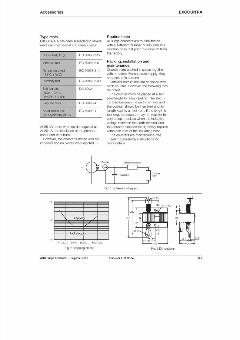
8/10/2019 ABB Extra High Voltage Surge Arresters Up to 420kV
http://slidepdf.com/reader/full/abb-extra-high-voltage-surge-arresters-up-to-420kv 91/96
ABB Surge Arresters — Buyer’s Guide S-2Edition 5.1, 2007-04
Accessories EXCOUNT-A
Type testsEXCOUNT-A has been subjected to severe
electrical, mechanical and climate tests:
Shock test, 15 g IEC 60068-2-27
Vibration test IEC 60068-2-6
Temperature test
(-55°C/+70°C)
IEC 60068-2-14
Humidity test IEC 60068-2-30
Salt fog test
(500h, +35°C,
95%RH, 5% salt)
DIN 50021
Impulse tests IEC 60099-4
Short-circuit test
(full asymmetry of 2.6)
IEC 60099-4
At 65 kA, there were no damages at all.
At 80 kA, the insulation of the primary
conductor was burnt.
However, the counter function was not
impaired and no pieces were ejected.
Routine tests All surge counters are routine-tested
with a sufficient number of impulses in a
pass/no pass test prior to despatch fromthe factory.
Packing, installation andmaintenanceCounters are packed in cases together
with arresters. For separate supply, they
are packed in cartons.
Detailed instructions are enclosed with
each counter. However, the following may
be noted.
The counter must be placed at a suit
able height for easy reading. The electri-
cal lead between the earth terminal andthe counter should be insulated and its
length kept to a minimum. If the length is
too long, the counter may not register for
very steep impulses when the inductive
voltage between the earth terminal and
the counter exceeds the lightning impulse
withstand level of the insulating base.
The counters are maintenance-free.
Refer to assembly instructions for
more details.
Fig. 1 Schematic diagram
Fig. 2 Stepping criteria Fig. 3 Dimensions
8/10/2019 ABB Extra High Voltage Surge Arresters Up to 420kV
http://slidepdf.com/reader/full/abb-extra-high-voltage-surge-arresters-up-to-420kv 92/96
EXAMPLE3 EXLIM Q120-EH145
Brown 1HSA410000-A 1HSA420000-A 1HSA430000-A
2004-06-03 XXXX EUR XXXX EUR
T-1 ABB Surge Arresters — Buyer’s GuideEdition 5.1, 2007-04
Order form
Purchase order
Project Handled by, e-mail or fax Tender referency no (if any)
Buyer Date (yyyy-mm-dd) Buyer reference
End user End user reference (if any)
Shipping terms Destination Means of transport
Freight forwarder (if FCA or FOB) Payment terms
Goods marking Delivery address
Inspection of routine tests Routine test standard Documentation language Rating plate language Currency
ItemsQuantity Arrester type designation
Color (porcelain) Line terminal Earth terminal Insulating base
Delivery date (EXW) yyyy-mm-dd Unit price (if known) Total price (if known)
Quantity Arrester type designation
Color (porcelain) Line terminal Earth terminal Insulating base
Delivery date (EXW) yyyy-mm-dd Unit price (if known) Total price (if known)
Quantity Arrester type designation
Color (porcelain) Line terminal Earth terminal Insulating base
Delivery date (EXW) yyyy-mm-dd Unit price (if known) Total price (if known)
Quantity Arrester type designation
Color (porcelain) Line terminal Earth terminal Insulating base
Delivery date (EXW) yyyy-mm-dd Unit price (if known) Total price (if known)
It is recommended that the following form is used when ordering EXLIM/PEXLIM surge arresters and accesso-
ries. Send to fax: +46 (0)240 179 83 or mail to [email protected].
No Yes
WW.CABLEJOINTS.CO.UK
THORNE & DERRICK UKTEL 0044 191 490 1547 FAX 0044 477 5371
TEL 0044 117 977 4647 FAX 0044 977 5582
WW.THORNEANDDERRICK.CO.UK
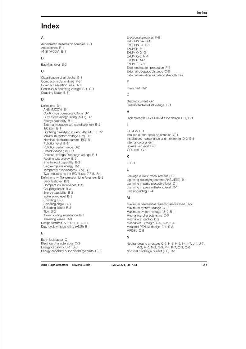
8/10/2019 ABB Extra High Voltage Surge Arresters Up to 420kV
http://slidepdf.com/reader/full/abb-extra-high-voltage-surge-arresters-up-to-420kv 93/96
ABB Surge Arresters — Buyer’s Guide U-1Edition 5.1, 2007-04
Index
Index
A
Accelerated life tests on samples G-1
Accessories R-1
ANSI (MCOV) B-1
B
Backflashover B-3
C
Classification of all blocks G-1
Compact-insulation lines F-3
Compact insulation lines B-3
Continuous operating voltage B-1, C-1
Coupling factor B-3
D
Definitions B-1
ANSI (MCOV) B-1
Continuous operating voltage B-1
Duty-cycle voltage rating (ANSI) B-1
Energy capability B-1
External insulation withstand strength B-2
IEC (Uc) B-1
Lightning classifying current (ANSI/IEEE) B-1
Maximum system voltage (Um) B-1
Nominal discharge current (IEC) B-1
Pollution level B-2
Pollution performance B-2
Rated voltage (Ur) B-1
Residual voltage/Discharge voltage B-1Routine test energy B-2
Short-circuit capability B-2
Single-impulse energy B-2
Temporary overvoltages (TOV) B-1
Two impulses as per IEC clause 7.5.5. B-1
Definitions — Transmission Line Arresters B-3
Backflashover B-3
Compact insulation lines B-3
Coupling factor B-3
Energy capability B-3
Isokeraunic level B-3
Shielding B-3
Shielding angle B-3
Shielding failure B-3 TLA B-3
Tower footing impedance B-3
Travelling waves B-3
Design features A-1, D-1, E-1, S-1
Duty-cycle voltage rating (ANSI) B-1
E
Earth fault factor C-1
Electrical characteristics C-3
Energy capability B-1, B-3
Energy capability & line discharge class C-3
Erection alternatives F-6
EXCOUNT-A S-1
EXCOUNT-II R-1
EXLIM P P-1
EXLIM Q-D O-1EXLIM Q-E N-1
EXLIM R M-1
EXLIM T Q-1
Extended station protection F-4
External creepage distance C-5
External insulation withstand strength B-2
F
Flowchart C-2
G
Grading current G-1
Guaranteed residual voltage G-1
H
High strength (HS) PEXLIM tube design E-1, E-3
I
IEC (Uc) B-1
Impulse current tests on samples G-1
Installation, maintenance and monitoring D-2, E-5
Internal corona G-1
Isokeraunic level B-3
ISO 9001 G-1
K
k C-1
L
Leakage current measurement R-2
Lightning classifying current (ANSI/IEEE) B-1
Lightning impulse protective level C-1
Lightning impulse withstand level C-1
Line upgrading F-4
M
Maximum permissible dynamic service load C-5
Maximum system voltage C-1Maximum system voltage (Um) B-1
Mechanical characteristics C-5
Mechanical loading D-2
Mechanical Strength C-5, D-2, E-4
Moulded PEXLIM design E-1, E-2
MPDSL C-5
N
Neutral-ground arresters C-6, H-3, H-5, I-4, I-7, J-4, J-7,
M-3, M-5, N-3, N-5, P-4, P-7, Q-3, Q-6
Nominal discharge current (IEC) B-1

8/10/2019 ABB Extra High Voltage Surge Arresters Up to 420kV
http://slidepdf.com/reader/full/abb-extra-high-voltage-surge-arresters-up-to-420kv 94/96
U-2 ABB Surge Arresters — Buyer’s GuideEdition 5.1, 2007-04
Index
O
Order T-1
Ordering data C-6
Ordering example C-6Order form T-1
Other sample tests G-1
P
Permissible static service load C-5
PEXLIM P J-1
HS PEXLIM P-T K-1
PEXLIM Q I-1
PEXLIM R H-1
HS PEXLIM T-T L-1
PEXLINK A-1, F-1, F-2, F-3, F-4, F-5, F-6
PEXLINK concept A-1, F-1
Pollution level B-2Pollution performance B-2
Polymer-housed arresters, PEXLIM E-1
Porcelain-housed arresters, EXLIM D-1
Power frequency reference voltage G-1
Power losses G-1
Product range A-2
Protection margins C-4
Protection philosophy F-2
PSSL C-5
Purchase order T-1
Q
Quality control and testing G-1
Accelerated life tests on samples G-1Classification of all blocks G-1
Grading current G-1
Guaranteed residual voltage G-1
Impulse current tests on samples G-1
Internal corona G-1
ISO 9001 G-1
Other sample tests G-1
Power frequency reference voltage G-1
Power losses G-1
Routine tests G-1
Tests on accessories G-1
Tests on assembled mechanical units G-1
Tests on ZnO blocks G-1
Test reports G-1
Tightness check (only for EXLIM arresters) G-1
Type tests G-1
R
Rated voltage C-1
Rated voltage (Ur) B-1
Remote reading R-2
Residual voltage/Discharge voltage B-1
Routine tests G-1
Routine test energy B-2
S
Sensor R-1
Shielding B-3
Shielding angle B-3Shielding failure B-3
Short-circuit capability B-2
Silicone as an Insulator E-4
Simplified selection procedure C-1
Single-impulse energy B-2
Special applications C-6
Statistical analysis R-2
Substitute for shield wires F-4
Surge Arrester Monitor R-1
Surge Counter S-1
Surge counting R-2
Switching impulse protective level C-1
Switching impulse withstand level C-1
T
T C-1
Table of contents A-1
Temporary overvoltage C-1
Temporary overvoltages (TOV) B-1
Tests on accessories G-1
Tests on assembled mechanical units G-1
Tests on ZnO blocks G-1
Test reports G-1
Tightness check (only for EXLIM arresters) G-1
TLA B-3
TOV C-1
TOV strength factor C-1 Tower footing impedance B-3
Transceiver R-1
Travelling waves B-3
Two impulses as per IEC clause 7.5.5. B-1
Type designation C-6
Type tests G-1
U
Uc C-1
Um C-1
Upl C-1
Ups C-1
Ur C-1
Uwl C-1
Uws C-1
Z
ZnO-blocks D-1, E-1, E-2

8/10/2019 ABB Extra High Voltage Surge Arresters Up to 420kV
http://slidepdf.com/reader/full/abb-extra-high-voltage-surge-arresters-up-to-420kv 95/96
ABB Surge Arresters — Buyer’s Guide U-3Edition 5.1, 2007-04
Customer notes
C u s t o
m e r
N o t e
s
8/10/2019 ABB Extra High Voltage Surge Arresters Up to 420kV
http://slidepdf.com/reader/full/abb-extra-high-voltage-surge-arresters-up-to-420kv 96/96
C a t a l o g u e P u b l : 1 H S M 9
5 4 3 1 2 - 0 0 e n S u r g e A r r e s t e r s B u y e r ’ s G u i d e , E d i t i o n 5 . 1 , 2 0 0 7 - 0 4
P r o d u c e r : H V P / M D M F
WW.CABLEJOINTS.CO.UK
THORNE & DERRICK UKTEL 0044 191 490 1547 FAX 0044 477 5371
TEL 0044 117 977 4647 FAX 0044 977 5582
WWW.THORNEANDDERRICK.CO.UK