abb kent-taylor · pdf fileabb kent-taylor is an established world force in the design and ......
TRANSCRIPT

ABB Kent-Taylor
Instruction Manual
Model 8036
Soduim Monitor
ABB Kent-Taylor
ABB Kent-Taylor
Sodium EIL8036
Sodium EIL8036
ABB KENT-TAYLOR
Health and SafetyTo ensure that our products are safe and without risk to health, the following points must be noted:
1. The relevant sections of these instructions must be read carefully before proceeding.
2. Warning labels on containers and packages must be observed.
3. Installation, operation, maintenance and servicing must only be carried out by suitably trained personnel and in accordance with theinformation given.
4. Normal safety precautions must be taken to avoid the possibility of an accident occurring when operating in conditions of high pressureand/or temperature.
5. Chemicals must be stored away from heat, protected from temperature extremes and powders kept dry. Normal safe handling proceduresmust be used.
6. When disposing of chemicals ensure that no two chemicals are mixed.
Safety advice concerning the use of the equipment described in this manual or any relevant hazard data sheets (where applicable) may beobtained from the Company address on the back cover, together with servicing and spares information.
Note.Clarification of an instruction or additional information.
Information.Further reference for more detailed information ortechnical details.
Use of Instructions
Warning.An instruction that draws attention to the risk of injury ordeath.
Caution.An instruction that draws attention to the risk of damage tothe product, process or surroundings.
Although Warning hazards are related to personal injury, and Caution hazards are associated with equipment or property damage,it must be understood that operation of damaged equipment could, under certain operational conditions, result in degradedprocess system performance leading to personal injury or death. Therefore, comply fully with all Warning and Caution notices.
Information in this manual is intended only to assist our customers in the efficient operation of our equipment. Use of this manualfor any other purpose is specifically prohibited and its contents are not to be reproduced in full or part without prior approval ofTechnical Communications Department, ABB Kent-Taylor.
The Company
ABB Kent-Taylor is an established world force in the design and manufacture ofinstrumentation for industrial process control, flow measurement, gas and liquid analysis andenvironmental applications.
As a part of ABB, a world leader in process automation technology, we offer customersapplication expertise, service and support worldwide.
We are committed to teamwork, high quality manufacturing, advanced technology andunrivalled service and support.
The quality, accuracy and performance of the Company’s products result from over 100 yearsexperience, combined with a continuous program of innovative design and development toincorporate the latest technology.
The NAMAS Calibration Laboratory No. 0255(B) is just one of the ten flow calibration plantsoperated by the Company, and is indicative of ABB Kent-Taylor’s dedication to quality andaccuracy.
RE
GIS T E R E D F
IRM
BS EN ISO 9001
St Neots, U.K. – Cert. No. Q5907Stonehouse, U.K. – Cert. No. FM 21106
Stonehouse, U.K. – Cert. No. 0255
EN 29001 (ISO 9001)
Lenno, Italy – Cert. No. 9/90A

1
CONTENTS
Section PageSection Page
1 INTRODUCTION ....................................................... 21.1 General .......................................................... 21.2 Sensor Unit ..................................................... 21.3 Transmitter Unit .............................................. 2
2 INSTALLATION ......................................................... 32.1 Fixing of Units ................................................ 3
2.1.1 Location ............................................ 32.1.2 Sensor Unit ....................................... 32.1.3 Transmitter Unit ................................ 4
2.2 Sample Requirements .................................... 42.3 External Pipe Connections ............................. 5
2.3.1 Inlet ................................................... 52.3.2 Drain ................................................. 5
2.4 Electrical Interconnections ............................. 52.4.1 Sensor unit ........................................ 52.4.2 Transmitter unit ................................. 5
2.5 Ancillary equipment ........................................ 72.5.1 Recorders ......................................... 72.5.2 Range Indication ............................... 7
2.6 Startup .......................................................... 8
3 PRINCIPLE OF OPERATION ................................... 93.1 Sensor Unit ..................................................... 93.2 Transmitter Unit ............................................ 10
3.2.1 Electronics Chassis ........................ 103.2.2 Front Panel Controls ....................... 103.2.3 Circuit Board Function Switch ........ 123.2.4 Alarms ............................................. 123.2.5 Analogue Outputs ........................... 12
4 CALIBRATION PROCEDURE ................................ 144.1 Manual Single Point Calibration ................... 144.2 Manual Two Point Calibration ...................... 144.3 Automatic Single Point Calibration .............. 154.4 Auto Calibration Preset Intervals ................. 15
5 MAINTENANCE ...................................................... 155.1 Chemical Solutions ...................................... 15
5.1.1 Reagent Solutions .......................... 155.1.2 Standard Solutions ......................... 165.1.3 Etch Solution ................................... 165.1.4 Salt Bridge Solution ........................ 16
5.2 Scheduled Servicing .................................... 165.2.1 Weekly ............................................ 165.2.2 Monthly ........................................... 165.2.3 3-Monthly ........................................ 17
5.3 Shutdown Procedures .................................. 175.3.1 Storage of Electrodes ..................... 17
5.4 Unscheduled Servicing ................................ 175.4.1 Calibration Fail Alarm ..................... 175.4.2 Malfunction of the Monitor .............. 185.4.3 Replacement of Plastic Tubing ....... 185.4.4 Simple Electronic Check ................ 18
6 SPARES LIST ........................................................ 20
7 SPECIFICATION ..................................................... 21
APPENDIX A ........................................................ 22A.1 Transmitter Unit ............................................. 22
A.1.1 Previous Type Digital CircuitBoard .............................................. 22
A.2 Shut-down Procedure .................................. 22A.2.1 Transmitter Unit .............................. 22
A.3 Spares List ................................................... 22
APPENDIX B ........................................................ 23Di-isopropylamine Reagent ..................................... 23
APPENDIX CCalibration for High Soduim Concentrations ........... 24

2
1 INTRODUCTION
1.1 GeneralThe Model EIL8036 is a microprocessor based on-line monitorfor measuring sodium in steam raising plant. Sample pointsinclude mixed bed outlets in water treatment plants, extractionpump discharge, boiler feed, boiler drum and steam.
Two range groups of 0.01µgk/g to 1mgk/g and 0.1µgk/g to10mgk/g are available with current output automaticallyswitched to cover two decades within one group at any onetime. Alternatively, a fixed range of 0.1µgk/g to 1mgk/g can beselected.
1.2 Description
1.2.1 Sensor UnitThe Sensor Unit consists of a metal case which houses theliquid handling equipment. This equipment is mounted on apanel which is secured to the back of the case with four M6captive bolts.
The Liquid Handling Section contains a clear acrylic flow cellwhere the sodium ion responsive electrode and the calomelreference electrode are presented to the flow sample. Theflowcell also houses a temperature sensor for temperaturecorrection of electrode output by the electronics. The pre-amplifier and the container for the reagent are mounted on theSensor Unit door. The junction box, convenient for theelectrical connection of the electrode pair, is also mounted onthe door.
The sample is pre-treated to achieve the correct pH value bythe introduction of an alkaline vapour.
For acid samples a pump, mounted on the door, isincorporated to supplement vapour addition.
Calibration is carried out by the use of standard solutions ofknown value under the control of the Transmitter Unit.
1.2.2 Transmitter UnitThe Transmitter Unit consists of a metal case of similarconstruction to that of the Sensor Unit with a chassis unitsupporting circuit boards and other electrical sub-assemblies.
The microprocessor electronics is in the form of a TransmitterUnit which performs four main functions:
• it interprets and displays a reading of sodiumreceived from the Sensor Unit,
• controls the calibration sequence,• displays sample temperature, and• provides the various outputs to remote equipment.
The display is a three digit, seven segment L.E.D. typeindicating the level of sodium and also providing informationon the operating mode. It informs the operator when theinstrument is in the calibration mode, and when the calibrationhas not been successful.
The case of the Transmitter Unit is suppressed against radio-frequency interference. A cable gland is provided on thebottom of the case for the cable to the liquid handling section.On the left-hand side is a gland plate drilled with six holeswhich may be enlarged to accept cable glands (not suppliedwith the equipment) suitable for the cables carrying the alarmsignals, the outputs to the recorder, etc. The maximum glandsize permissible is PG21.

3
490mm
8036-100/200With Door Open
Suggested Installation Layout
Up to 100mm8036-200
8036-100
Drain
SampleInput
300mm required for standardsolution container.
8036 - 100
8036 - 200
SampleInlet
Fig. 2.2 System Layouts
Fig. 2.3 Transmitter Unit Dimensions and Installation
2.1 Fixing of Units (Figs. 2.1, 2.2, 2.3 and 2.4)
2.1.1 Location and Layout (Figs. 2.1 and 2.2)Both units should be mounted in a clean, vibration-freesituation, avoiding direct radiant heat, sunlight and draughts.Areas containing chlorination equipment should also beavoided.
The Sensor Unit should be mounted not more than 10m fromits associated sample cooler (see below). The Transmitter Unitmay be mounted alongside or up to 100m away from theSensor Unit. If the Transmitter Unit is to be mounted directlyabove the Sensor Unit, allow at least 300mm separation
2 INSTALLATION
Transmitter Unit
Standard Solution Container
Quick Release CouplingSensor Unit
Fig. 2.1 Normal Mounting Arrangement ShowingPosition of Standard Solution Bottle
between the units for access to the standard solution containers.
2.1.2 Sensor Unit (Fig. 2.3)Holes in the case for wall-mounting the unit are suitable for 8mm diameter fasteners. Sufficient space must be left in front of the
300mm
230mm8.5mm
EarthStudM6
PilotHoles
30mmInterconnectingCable Gland 110mm
230m
m
GlandPlate
68mm
115mm
200mm
10mm
20m
m
300m
m
195m
m
150m
m
105m
m
2 INSTALLATION…

4
case for access.
2.1.3 Transmitter Unit (Fig. 2.4)Wall mounting is by four 8mm diameter fasteners on 230 x 230mm centres. The door of the case is equipped with a lock, and a
window to observe the display.
Note. Take out the desiccator and keep itin a safe place, sealed in its plastic bag, until
200mm
25mm
25m
m
300mm
230mm 8.5mm
Blank
25m
m
75 mm35mm35mmTo Fit
10mmFlexibleTube
160mm
20mmEarthStudM6
10mm
400m
m
330m
m
25mm
Inter-ConnectingCableGland
1/4" O.D.StainlessSteelTube
Connect to agood known earth
40mm
6.3mm O.D.Compression
Fitting
For access to wall mounting holes remove the chassis unit as follows:
1 Unlock the door and open it fully.
2 A small coin may be used to release the front panel by turning the four black fasteners by 1/4 turn (either direction).
3 Hold the front panel with two fingers through the slot at the left side. Ease the front panel forward over the Range Switch knob.
4 Remove the safety earth (ground) bonding leads attached to the metal case.
5 Release the captive screws securing the chassis assembly to the back of the case and remove the chassis.
Fig. 2.4 Sensor UnitDimensions and Installation
…2 INSTALLATION
required for use – see Section 2.6.
2.2 Sample Requirements
Warning. The maximum pressures and temperatures specified must not be exceeded.
Where pressure reducing equipment is being used it is recommended, for safety reasons, that a pressure relief valve beinstalled between this and the sample inlet to the monitor.
The sample should be brought to the temperature and pressure suitable for measurement – see Section 7, by means of samplecoolers and pressure reducing equipment.

5
2 INSTALLATION…
2.3 External Pipe Connections
2.3.1 InletThe sample should be connected to the Sensor Unit by meansof 6.3mm (1/4in) o.d. tubing (stainless steel or rigid plastic).Connect this to the sample inlet coupling on the right-handside of the panel via the grommet in the floor of the case.
The inlet tubing should be of sufficient wall thickness towithstand the highest sample pressure and the pipe lengthsshould be kept short. The inlet pipe should be bent to a rightangle outside the case to allow future removal of the liquidhandling panel when required.
Where particulate matter is present (e.g. magnetite in boilersamples) it is recommended that a 60 micron sample filter isfitted to the sample line.
A shut-off valve (not supplied with the equipment) is necessaryin the sample inlet.
2.3.2 DrainThe drain from the tundish at the bottom of the Sensor Unitcase consists of two stub pipe connections suitable for 10mm(3/8 in) bore plastic or rubber tubing. Alkaline effluent from themonitor flow cell appears at one connection and waste samplefrom the other.
The two connections can either be linked by a ‘Y’ piece andtaken to a contaminated drain, or they can be kept separateand led to appropriate drains.
2.4 Electrical Interconnections
Warning.• Before making any connections, ensure that the power
supply and high voltage power-operated control circuitsare switched off.
• This equipment operates on a.c. mains supply voltageelectricity. Suitable safety precautions must always betaken to avoid the possibility of electric shock.
2.4.1 Sensor UnitThe 8-way cable to connect the Sensor Unit to the TransmitterUnit is preformed and is supplied already connected to theSensor Unit. This is to avoid the need to open the pre-amplifierbox which could admit moisture, and because of the very highsource impedance of the sodium electrode (up to 5000Mohm,at sample temperature of 5°C), would affect the instrumentperformance. For distances between the Sensor Unit andTransmitter Unit greater than 2m, the cable is extended usinga junction box mounted adjacent to the Sensor Unit, and therequired length of 8-way cable.
The 2-way cable is for the pump supply.
Note. A stud terminal is fitted to the bottom of theSensor Unit case and must be connected to a good knownearth (ground).
2.4.2 Transmitter Unit (Fig. 2.5)Access to make the necessary connections is gained byremoving the chassis unit as described in Section 2.1.2.
a) Cut the cable from the Sensor Unit to a length to reach theTransmitter Unit easily to terminate on terminal block TB2on the analogue board.
b) Push the end of the cable through the gland in the base ofthe Transmitter Unit.
c) Open the Transmitter Unit door, remove the front panel andpull the cable through the gland.
d) Noting that the screening braid terminates at the cablegland and is prepared as shown in Fig. 2.5, prepare thecable end and attach it to the terminal block TB2. Theterminal block may be pulled off the pins on the board ifrequired.
Caution. The terminal block for Sensor Unitconnection has eight terminals, whereas there are 12 pinson the board. Ensure that the correct eight pins arechosen for connection; these are marked with a separate‘box’ – see the following text and Fig 2.5.
Pass the cables through the glands, and noting that Pin 1 ofeach block is nearest the top of the case, prepare the ends andattach them to the terminal blocks as follows – see also Fig.
Analogue board TB1 (top edge):
PIN 1 2 3 4 5 6 7 8 9 10
R4
R3
R2
R1
Four sets ofnormallyopen contacts,one of whichcloses toshow range ofmeasurementremotely.
0VNOCOMNOCOMNOCOMNOCOM0V
Analogue board TB2 (middle): PIN 1 2 3 4 5 6 7 8 9 10
Isolatedcurrentoutputs
0VNot used+–Not usedNot used+–Not used0V

6
Voltage Selector Fuse 2A Spare Fuse
Inner Insulation
Brass Tube Inside Braid
Outer Insulation
Clamps on Braid
Soft Plastic Insert
ExternalAlarmContacts
CalibrationIndication
CalibrateFailure
Alarm 2
Alarm 1
NOCOMNCNOCOMNCNOCOMNCNOCOMNC
Notused
IsolatedCurrentOutputs
Screen
Output 2
Screen
RemoteIndication ofMeasurementRange
Range 4
Range 3
Range 2
Range 1
TB1
TB2
TB3
WHRDBLVIGNYEBNBK
Not used
Not used
PowerSupplyCable
Output 1 Not used Not used
W HR DB LV IG NY EB NB K
Pump Motor Switchand Connector Block
…2 INSTALLATION
Fig. 2.5 Electrical Connections at Transmitter Unit
Note. A stud terminal is fitted to the bottom of theTransmitter Unit case and must be connected to a goodknown earth (ground).
7
2 INSTALLATION …
this must be set to the correct value before connecting theinstrument to the supply – see Fig. 2.5.
Connect the power supply input as follows:
LineNeutralEarth (Ground)
Supply input
2.5 Ancillary Equipment
2.5.1 RecordersThe choice of two different isolated recorder output signalsenables the instrument to be used with a wide variety ofrecording and data processing equipment. The loadrequirements are set out in Section 7, and the positions of thecircuit board switches are given in Section 3.2.3
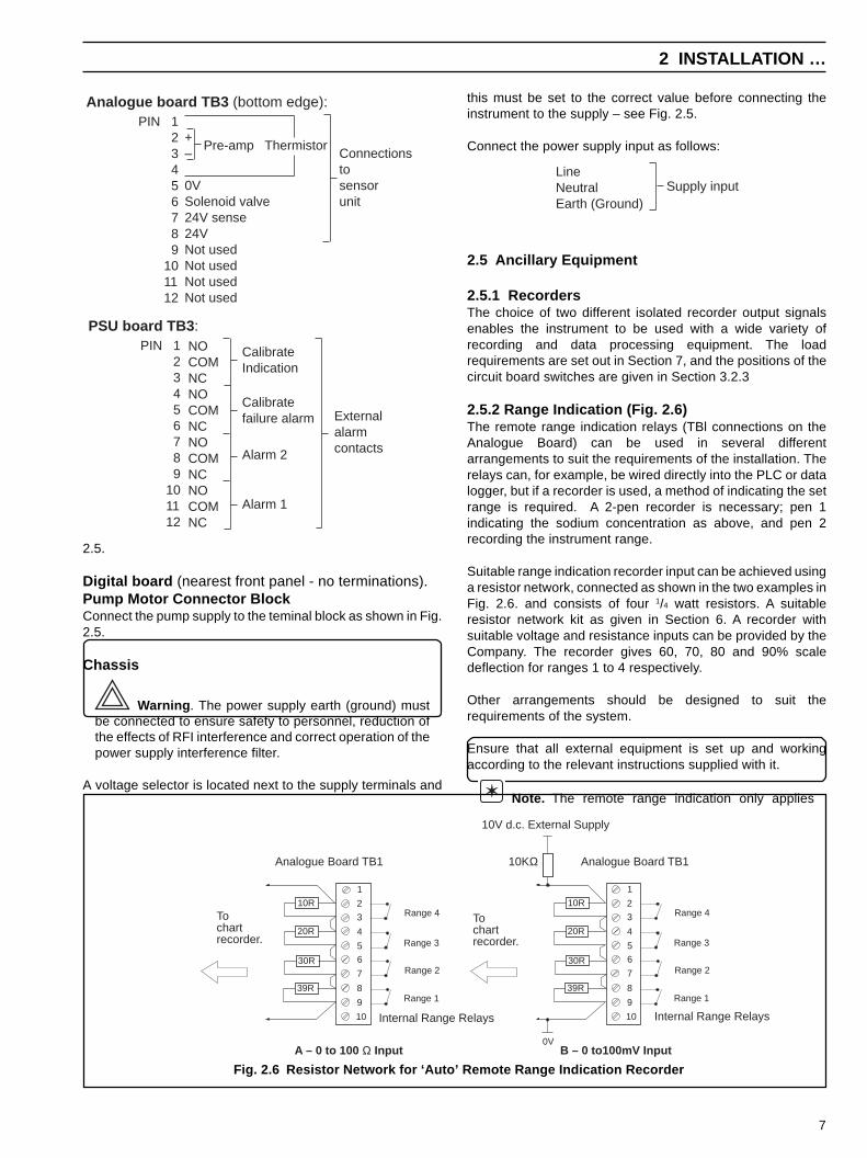
2.5.2 Range Indication (Fig. 2.6)The remote range indication relays (TBl connections on theAnalogue Board) can be used in several differentarrangements to suit the requirements of the installation. Therelays can, for example, be wired directly into the PLC or datalogger, but if a recorder is used, a method of indicating the setrange is required. A 2-pen recorder is necessary; pen 1indicating the sodium concentration as above, and pen 2recording the instrument range.
Suitable range indication recorder input can be achieved usinga resistor network, connected as shown in the two examples inFig. 2.6. and consists of four 1/4 watt resistors. A suitableresistor network kit as given in Section 6. A recorder withsuitable voltage and resistance inputs can be provided by theCompany. The recorder gives 60, 70, 80 and 90% scaledeflection for ranges 1 to 4 respectively.
Other arrangements should be designed to suit therequirements of the system.
Ensure that all external equipment is set up and workingaccording to the relevant instructions supplied with it.
Note. The remote range indication only applies
10V d.c. External Supply
0V
10KΩ
10R
20R
30R
39R
Tochartrecorder.
Range 4
Range 3
Range 2
Range 1
10R
20R
30R
39R
1
2
3
4
5
6
7
8
9
10
Range 4
Range 3
Range 2
Range 1
Internal Range Relays
Analogue Board TB1
A – 0 to 100 Ω Input B – 0 to100mV Input
1
2
3
4
5
6
7
8
9
10
Analogue Board TB1
Tochartrecorder.
Internal Range Relays
Fig. 2.6 Resistor Network for ‘Auto’ Remote Range Indication Recorder
Analogue board TB3 (bottom edge): PIN 1 2 3 4 5 6 7 8 9 10 11 12
+–
0VSolenoid valve24V sense24VNot usedNot usedNot usedNot used
Pre-amp ThermistorConnectionstosensorunit
PSU board TB3 : PIN 1 2 3 4 5 6 7 8 9 10 11 12
NOCOMNCNOCOMNCNOCOMNCNOCOMNC
CalibrateIndication
Calibratefailure alarm
Alarm 2
Alarm 1
Externalalarmcontacts
2.5.
Digital board (nearest front panel - no terminations).Pump Motor Connector BlockConnect the pump supply to the teminal block as shown in Fig.2.5.
Chassis
Warning . The power supply earth (ground) mustbe connected to ensure safety to personnel, reduction ofthe effects of RFI interference and correct operation of thepower supply interference filter.
A voltage selector is located next to the supply terminals and

8
when the front panel switch is set to ‘auto’.
2.6 Start-Up (Figs. 2.7, 2.8 and 3.5)a) Open the Transmitter Unit door and remove the front panel
if this has not already been done.
b) Remove the desiccator from its sealed bag and place itinside the Transmitter Unit.
c) Switch the battery switch SW10 to ‘ON’ – see Fig. 3.5.
d) Replace the front panel and secure by pressing in the fourplastic fasteners.
e) Power up the monitor at the external source and set theRange Switch to AUTO
f) Open the Sensor Unit door and remove the cover from thejunction box located on the door.
g) Unpack the sodium electrode and carefully remove therubber teat. Connect the electrode to the red connector(see Fig. 2.8) and then slide the electrode into thecylindrical plastic holder supplied – see Fig. 2.7. Locate the‘O’ ring (which is packed in the central chamber of the flowcell) and carefully position it on the stem of the electrodejust above the bulb. Carefully screw the holder into the
…2 INSTALLATION
the bottom of the chamber.
Note. It is extremely important that the ‘O’ rings arecorrectly fitted and that the inside of the electrodeconnections are dry and completely sealed. Moisturereduces the circuit impedance and affect the performance
central chamber so the ‘O’ ring is compressed and the bulbof the electrode is just above the bottom of the chamber.
h) Unpack the reference electrode and remove the rubberteat. Connect the electode to the black connector (see Fig.2.8) and release the black rubber filling hole plug. Fit the ‘O’ring supplied over the electrode body and position theelectrode centrally in the right-hand chamber of the flow-cell so that the ceramic plug is between 5 and 10mm from
Ensure 'O' ringsare fitted
1
2 Tighten each cable termination to ensure a good seal.
Fig. 2.8 Electrode Connections
of the monitor.
j) Fill reagent solution container with appropriate solution(see Section 5.1) .
k) Open the shut-off valve upstream of the Sensor Unit andadjust until sample is overflowing from the constant headunit. (Note the max. and min. flow rates given in Section 7).
l) Switch on the pump, if required (see Section 3.1).
m) Leave for at least one hour and then check for leaks.
n) Set up the transmitter as described in Section 3.2.3.
o) Carry out a calibration as detailed in Section 4.
p) The monitor now in operation, the lamp adjacent to the unitof measurement being illuminated.
q) If desired, turn the range switch to one of the non-autoranges.
r) Press the ALARM 1 button and use the UP/DOWN buttonsto set to the desired value. Repeat for ALARM 2.
Fig. 2.7 Flow Cell
Entrainment tube
Sodiumelectrode
Plasticholder
'O' Ring0211 064
Referenceelectrode
'O' Ring0211 064
'O' Ring0211 119
Drain
5 - 10 mm
Thermistor
BlackRed

9
3 PRINCIPLE OF OPERATION
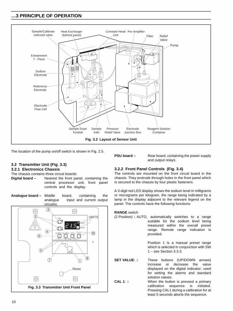
3.1 Sensor Unit (Fig. 3.1 and 3.2)A flow schematic is shown in Fig. 3.1 and the the physicallayout of the unit is shown in Fig. 3.2.
The sample enters via a compression fitting at the bottom ofthe case and passes through one half of a heat exchangerwhich is used during the calibration sequence to bring thestandard solution close to the temperature of the sample. Thisminimises the calibration time.
From the heat exchanger the sample passes through asolenoid valve to the constant head unit which removes theeffect of changes in sample pressure and flow-rate. A smalltube overflowing into the constant head on one side, ensuresself starting when the sample is lost, and enables the monitorto function over a wide sample flow.
The sample is then delivered to the ‘T’ piece and stainlesssteel entrainment tube, where an alkaline vapour reagent isadded to the sample to raise the pH value, before beingpresented to the sodium and reference electrodes mounted ina flow cell. The sample leaves the flow cell and is passed todrain at the bottom of the case.
The potential developed between the sodium ion-responsiveelectrode and calomel reference electrode is logarithmic withrespect to changes in sodium ion concentration. The signalfrom the electrode pair is connected via a junction box to avoltage-to- current pre-amplifier whose output is connected to
the Transmitter Unit via the interconnection cable.
A temperature sensor fitted into the flow cell, detects thetemperature of the sample. The sensor is connected to theTransmitter Unit which compensates for changes in outputfrom the electrode pair over a range of 5 to 55°C.
Calibration of the monitor is carried out under the control of themicroprocessor. After connection of the calibration tube to thestandard solution container, the appropriate button on theTransmitter Unit is pressed. The solenoid valve on the liquidhandling panel is energised changing over from sample tostandard solution which first passes through the second half ofthe heat exchanger. The solution is presented to the electrodepair via the constant head unit and the vapour entrainmenttube.
Although the solenoid valve is closed to the sample during acalibration sequence, under sample pressure the pressurerelief valve opens, allowing sample to pass through the heatexchanger, bringing the standard solution to a similar value.
A pump supplements the quantity of reagent vapour deliveredby the entrainment device. This pump is only required when anacid sample is to be monitored and satisfactory pH conditionscannot be achieved by normal entrainment. A satisfactoryeffluent pH depends on the degree of acidity of the sampletogether with the sodium concentration range which is to bemonitored – see Section 5.4.2.
A separate drain from the flow cell is provided so that effluentpH can be measured.
3 PRINCIPLE OF OPERATION…
PD
Foul Clean
Thermistor
SodiumElectrode Reference
Electrode
Drain
Flowcell
PressurereliefValve
Heat Exchanger
SampleInlet
Sample/CalibrateSolenoid Valve
ConstantHead Unit Standard
SolutionContainer
Pre-amplifierValve Supply
Output toTransmitter
24V Supply
TemperatureCompensation
Entrainment'T' Piece
Fig. 3.1 Schematic Flow Diagram
10
…3 PRINCIPLE OF OPERATION
Constant HeadUnit
Heat Exchanger(behind panel)
Sample/Calibratesolenoid valve
EntrainmentT - Piece
SodiumElectrode
Reference Electrode
ElectrodeFlow Cell
Sample DrainTundish
SampleInlet
PressureRelief Valve
ElectrodeJunction Box
Reagent SolutionContainer
Pre-Amplifier
Pump
Filter ReliefValve
Fig. 3.2 Layout of Sensor Unit
The location of the pump on/off switch is shown in Fig. 2.5.
3.2 Transmitter Unit (Fig. 3.3)3.2.1 Electronics ChassisThe chassis contains three circuit boards:Digital board – Nearest the front panel, containing the
central processor unit, front panelcontrols and the display.
Analogue board – Middle board, containing theanalogue input and current outputcircuitry.
Fig. 3.3 Transmitter Unit Front Panel
CAL
ALARM 1 ALARM 2 STD1 STD2
F1 F2 S%
mg kg-1
µg kg-1
RANGE
AUTO 1
1
2
3
4
5
6
7
1
2
8
0
Reset
UNITS
Temp.
9
PSU board – Rear board, containing the power supplyand output relays.
3.2.2 Front Panel Controls (Fig. 3.4)The controls are mounted on the front circuit board in thechassis. They protrude through holes in the front panel whichis secured to the chassis by four plastic fasteners.
A 3-digit red LED display shows the sodium level in milligramsor micrograms per kilogram, the range being indicated by alamp in the display adjacent to the relevant legend on thepanel. The controls have the following functions:
RANGE switch(2 Position) 1 AUTO, automatically switches to a range
suitable for the sodium level beingmeasured within the overall presetrange. Remote range indication isprovided.
Position 1 is a manual preset rangewhich is selected in conjunction with SW1 – see Section 3.3.3.
SET VALUE : 2 These buttons (UP/DOWN arrows)increase or decrease the valuedisplayed on the digital indicator; usedfor setting the alarms and standardsolution values.
CAL 1 : 3 When the button is pressed a primarycalibration sequence is initiated.Pressing CAL1 during a calibration for atleast 5 seconds aborts the sequence.
11
3 PRINCIPLE OF OPERATION…
CAL 2 : 4 When the button is pressed a secondarycalibration sequence is initiated.Pressing CAL2 during a calibration for atleast 5 seconds aborts the sequence.
Alarm 1/Alarm 2 :5 Used in conjunction with the UP/DOWNbuttons to set the values at which thealarm relays operate.
F1: 6 Pressing this button during a calibrationsequence, displays the output from thesodium electrode.
F2: 7 Holding this button while pressing andreleasing RESET initiates a COLDSTART.
Pressing F1 and F2 together gives the offset (in mV)generated by the electrode at the last calibration.
STD1: 8 Used in conjunction with the UP/DOWN
STD2: 9 buttons to set the values of the standardsolutions into the instrument.
S%: 0 Pressing STD1 and STD2 together givesan indication of the electrode % slopevalue, which was calculated during thelast TWO POINT CALIBRATION.
Temp. Pressing F2 and STD1 together displaysthe temperature (in °C) of the solution in
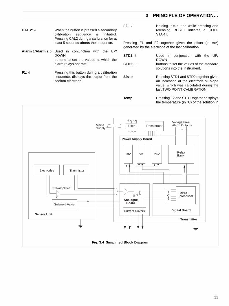
Fig. 3.4 Simplified Block Diagram
Sensor Unit
Solenoid Valve
Electrodes Thermistor
Pre-amplifier
FilterMains Supply
Voltage FreeAlarm Outputs
RelayBank24V5V±8V
Power Supply Board
AnalogueBoard
Digital Board
Micro-processor
IC6
Current Drivers
Transmitter
Transformer

12
…3 PRINCIPLE OF OPERATION
the flowcell.
RESET: Used to regain control of the instrumentin the unlikely event of a malfunction dueto high supply transient, etc (this buttonis not visible when the cabinet door isclosed).
SW1
1 2 3 4 5 6 7 8
Current Output (mA)
0-10 0-20 4-20
ON OFFOFF
ONOFFON
Output Law
LinearLog
OFFON
Low Cal. Solution
Standard Sample
OFFON
Range Group
1 2
OFFON
AutoCal
OFFON
Alarm 2Failsafe Normal
OFFON
Alarm 1Failsafe Normal
OFFON
3.2.3 Circuit Board Function Switch SW1 (Fig. 3.5)A series of eight ON/OFF switches in a dual-in-line package isread by the microprocessor and provides controlling functions
RangeGroup 1 (SW1.5 OFF)0.1µg/kg to 10mg/kg
Group 2 (SW1.5 ON)0.01µg/kg to 1mg/kg
AUTO
100µg/kg to 10mg/kg10µg/kg to 1mg/kg
1 to 100µg/kg0.1 to 10µg/kg
10µg/kg to 1mg/kg1 to 100µg/kg0.1 to 10µg/kg0.01* to 1µg/kg
1 Not Used 0.1µg/kg to 1mg/kg
for the alarms, output current and calibration – see Table 3.1.
Table 3.1 Circuit Board Function Switch
Table 3.2 Range Groups
* Electronically, this is the lowest concentration which can bedisplayed; however, it is unlikely to be achieved in practice. Lowconcentration sodium measurements depend on sample andelectrode conditions.
3.2.4 Alarms
Note. The alarms cannot be set during a calibrationsequence.
Two sodium concentration alarm control relays are provided,each having one pair of changeover contacts rated at 2A 250Va.c. (non-inductive). It is intended that both should operate as‘high’ alarms i.e. when the sodium level increases beyond theset value.For example, the lower setting may act as a warning that thesodium level has increased beyond a reasonable level, andthe higher setting may be used in a shut down capacity. Thealarm values are set by pressing the relevant ALARM button inconjunction with the SET VALUE buttons.
Terminal connections for alarms are shown in Section 2.4 andswitches SW1.7 and SW1.8 determine contacts which areclosed in non-alarm conditions – see Section 3.2.3.Functions are as follows:
• In NORMAL the relays are de-energised i.e. NC contactsare closed.
• In FAILSAFE the relays are energised i.e. NO contacts areclosed. Thus if the power source fails, both external alarmsare flagged indicating a malfunction.
Two other sets of relay contacts are provided. One setchanges over during a calibration sequence and the other setchanges over to indicate failure to calibrate .
3.2.5 Analogue Outputs (Table 3.2, Figs. 3.6 & 3.7)Two identical isolated current outputs are available. Bothoutputs may be set to one of the three current ranges bymeans of switches SW1.1 and SW1.2. In each case the uppercurrent limit corresponds to the full-scale reading of the rangedisplayed on the front panel.Fig. 3.5 Location of Items on Digital Board
1
8
Push-ButtonControls
BatterySwitchSW10Battery
DigitalDisplay
RangeSwitchSW2
FunctionSwitch
SW1 – 1 to 8

13
…3 PRINCIPLE OF OPERATION
Note. If SW1.1 is set to ON and SW1.2 is set toOFF, no valid output is produced.
In AUTO two current outputs cover five decades of sodiumconcentration divided into four overlapping ranges. Theoverall range is determined by the RANGE GROUP selectedby the position of SW1.5
Within the selected RANGE GROUP both the availablecurrent outputs represent two decades of sodiumconcentration at any one time. In AUTO the monitor switchesautomatically between these ranges as the sodiumconcentration varies. The following points regarding rangesshould be noted:
a) The range selection only refers to the current output, thedigital display covers the full range capability of the
monitor.
b) If the concentration is outside the individual range orRANGE GROUP selected, the digital display flashes -(reading) - ‘out’ - (reading) - ‘out’ -, in every other way themonitor functions normally.
c) In AUTO, as the concentration increases, the switching tothe next range takes place at 100% of the current output,giving a 50% output on the upper range (10% in linearoutput). When however the concentration decreases, theswitching takes place at 0% of the current output, giving a50% output on the lower range (10% in linear output). Thisprovides a range switching hysteresis of one decade.
d) At all times in AUTO the current output range can bemonitored or recorded remotely using the four remoteRANGE INDICATION RELAY contacts.
1 2 3 4 5 6 7 8 910 20 30 40 50 60 7080901000
10
20
30
40
50
60
70
80
90
100
0 15
.05
23
.86
30
.10
34
.95
38
.91
42
.25
45
.15
47
.71
50
.00
65
.05
73
.86
80
.10
84
.95
88
.91
92
.25
95
.15
97
.71
10
0.0
0Sodium concentration x minimum scale value
% C
urr
en
t o
utp
ut
% O/P
Fig. 3.6 Logarithmic Current Output – Two Decade
Fig. 3.7 Logarithmic Current Output – Four Decade
0.1 1.0 10 100 1000µg/kg0
10
20
30
40
50
60
70
80
90
100
0 25
50
75 100.0
0
Sodium concentration x minimum scale value
% C
urr
en
t o
utp
ut
% O/P

14
4 CALIBRATION PROCEDURE
e) In RANGE1 and SW1.5 set to ON a fixed range of 0.1µg/kgto 1mg/kg is selected.
The outputs can be configured to be LOGARITHMIC orLINEAR determined by the position of SW1.3. It should benoted that when the LOGARITHMIC output is selected, theoutput represents two decades of concentration (e.g.0.1 to 10, 1 to 100µg/kg etc.). When the LINEAR output isselected however, the output represents zero to the full-scalereading (eg. 0 to 10, 0 to 100µg/kg etc.)
Calibrations can be carried out manually (single or two point)or automatically (single point only).
Before carrying out a calibration sequence, rinse the solutioncontainers with high purity water and fill with fresh standardsolution. A single point calibration only requires one solution(STD1). If a two point calibration is to be carried out, it isrecommended that the lower value solution should be usedfirst.
Pressing F1 during the calibration displays the indicatedsodium concentration, but the zero or slope correction onlytakes place at the end of each calibration sequence.
Note . A calibration sequence can be aborted bypressing the CAL1 during the first or CAL2 buttons duringthe second calibration sequence until 'Abt' is displayed.Normal operation i.e. monitoring sample is resumed usingthe calibration constants from previous completecalibration sequences.
4.1 Manual Single Point CalibrationDuring this sequence the display on the front panel indicates'CA1'. The full calibration sequence, performed as follows,takes approximately 45 minutes.a) The value of the standard solution is entered by first
pressing the STD1 button and using the UP/DOWNbuttons to set the concentration of the solution.
b) Press CAL1 and the display counts '5, 4, 3, 2, 1' before thesequence is initiated to prevent a calibration being startedby accidental pressing of the CAL1 button.
c) The solenoid valve is energized which allows the sample tobe replaced with the standard solution (STD1), from theexternal bottle.
d) Both the concentration alarms are de-energised and therelay contacts for remote CAL indication change over.
e) The current output follows the calibration sequence.
f) After 15 minutes the microprocessor reads the output from
the electrode pair plus the temperature, then calculates thezero correction required to bring the reading to the presetstandard solution concentration. The display now revertsto showing the sodium concentration value.
g) The solenoid valve is de-energised to allow sample to flowthrough the electrode flow cell.
h) The 'RUN' (sample) mode is resumed and 30 minutes areallowed for the system to recover before the alarms aremade active and the remote CAL relay is de-energised.
Pressing F1 and F2 together, after a calibration, causes thedisplay to show the mV offset. This is the differencebetween the voltage from the electrode and that expectedfrom a typical electrode. The range is ±99mV. Themagnitude of the offset is not important. However, largedeviations from one calibration to the next indicatesinstability, and the cause should be investigated, e.g. afaulty sodium or reference electrode, poor connections etc.
4.2 Manual Two Point CalibrationThis sequence follows on from the single point calibration, but isselected by pressing CAL2 while the display indicates 'CA1'. Theright hand decimal point is illuminated during the calibrationsequence to indicate that two point calibration has been selected.When the second standard solution is being introduced thedisplay indicates 'CA2'. The full calibration sequence takesapproximately 1 hour and performs the following:a) The values of the standard solutions are entered by first
pressing the STD1 button and using the UP/DOWN buttons toset the concentration of the first solution. Then press theSTD2 button and set the concentration of the second solutionusing the UP/DOWN buttons.
b) Follow the sequence for single point calibration from step b) tostep e) in Section 4.1.
c) During this period, while 'CA1' is displayed, press CAL2. Thedisplay counts '5, 4, 3, 2, 1' to avoid accidental initiation, andthe right hand decimal point then illuminates.
d) At the end of the first calibration sequence 'CA2' flashes onthe display, indicating that the second standard solutionshould be connected to the monitor. Once this has been donethe CAL2 button is pressed to continue the sequence.
Note. The microprocessor allows 15 minutes toelapse, between the end of the first calibration sequence(CA1) and pressing the CAL2 button to start the secondcalibration sequence (CA2). If this time is exceeded, the twopoint calibration is aborted.
e) 15 minutes later, the microprocessor reads the output fromthe electrode pair plus the temperature, then, calculates theslope correction required to bring the reading to the secondpreset standard solution concentration. If the slope value fallsbelow approximately 83% the external CAL FAIL alarm isactivated and the display shows ‘CF’ indicating the sodiumelectrode is in need of attention.
15
f) If the slope value is above this minimum value the instrumentcompletes the sequence as in steps (g) and (h) of Section 4.1,and the display reverts to displaying the concentration value.
The slope value can be displayed at any time, including after aCAL FAIL, to indicate the condition of the sodium electrode.Keeping a note of the slope value gives an early warning of a CALFAIL condition.
The voltage offset can also be displayed – see Section 4.1
4.3 Automatic Single Point Calibration
Note. It is recommended that a manual, two pointcalibration is first carried out before initiating theautomatic calibration sequence.
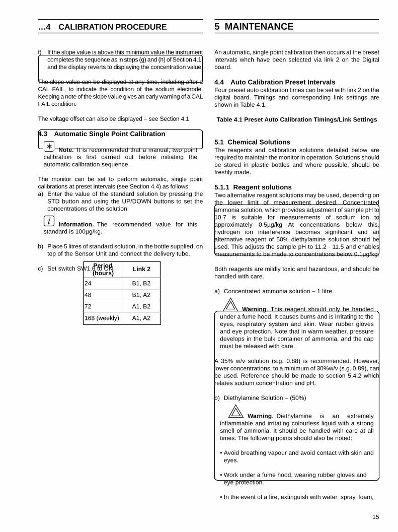
The monitor can be set to perform automatic, single pointcalibrations at preset intervals (see Section 4.4) as follows:a) Enter the value of the standard solution by pressing the
STD button and using the UP/DOWN buttons to set theconcentrations of the solution.
Information. The recommended value for thisstandard is 100µg/kg.
b) Place 5 litres of standard solution, in the bottle supplied, ontop of the Sensor Unit and connect the delivery tube.
c) Set switch SW1.6 to ON.
…4 CALIBRATION PROCEDURE 5 MAINTENANCE
An automatic, single point calibration then occurs at the presetintervals whch have been selected via link 2 on the Digitalboard.
4.4 Auto Calibration Preset IntervalsFour preset auto calibration times can be set with link 2 on thedigital board. Timings and corresponding link settings areshown in Table 4.1.
Table 4.1 Preset Auto Calibration Timings/Link Settings
5.1 Chemical SolutionsThe reagents and calibration solutions detailed below arerequired to maintain the monitor in operation. Solutions shouldbe stored in plastic bottles and where possible, should befreshly made.
5.1.1 Reagent solutionsTwo alternative reagent solutions may be used, depending onthe lower limit of measurement desired. Concentratedammonia solution, which provides adjustment of sample pH to10.7 is suitable for measurements of sodium ion toapproximately 0.5µg/kg At concentrations below this,hydrogen ion interference becomes significant and analternative reagent of 50% diethylamine solution should beused. This adjusts the sample pH to 11.2 - 11.5 and enablesmeasurements to be made to concentrations below 0.1µg/kg.
Both reagents are mildly toxic and hazardous, and should behandled with care.
a) Concentrated ammonia solution – 1 litre.
Warning . This reagent should only be handledunder a fume hood. It causes burns and is irritating to theeyes, respiratory system and skin. Wear rubber glovesand eye protection. Note that in warm weather, pressuredevelops in the bulk container of ammonia, and the capmust be released with care.
A 35% w/v solution (s.g. 0.88) is recommended. However,lower concentrations, to a minimum of 30%w/v (s.g. 0.89), canbe used. Reference should be made to section 5.4.2 whichrelates sodium concentration and pH.
b) Diethylamine Solution – (50%)
Warning . Diethylamine is an extremelyinflammable and irritating colourless liquid with a strongsmell of ammonia. It should be handled with care at alltimes. The following points should also be noted:
• Avoid breathing vapour and avoid contact with skin andeyes.
• Work under a fume hood, wearing rubber gloves andeye protection.
• In the event of a fire, extinguish with water spray, foam,
Period(hours)
Link 2
24 B1, B2
48 B1, A2
72 A1, B2
168 (weekly) A1, A2

16
2µg/kg sodium ions and a specific conductivity of less thanapproximately 0.2µS/cm.
5.1.3 Etch Solution (for use on applications where thesample sodium concentration is below 1 µg/kg – see also Section5.2.2).
Warning. Sodium Fluoride is toxic. Avoid inhaling thedust and prevent contact with skin and eyes. Wear a dustmask, rubber gloves and eye protection. When prepared, theetch solution contains 0.1M Hydrofluoric acid (0.2% HF).Take care to prevent contact with skin and eyes.
Dissolve 5.0 (±0.2)g analytical grade sodium fluoride, NaF, inapproximately 400ml high purity water. Add to this solution 20(±0.2)ml 5M acetic acid *, CH3COOH, and dilute to 1 litre.
* 5M acetic acid can be prepared from concentrated acid byadding 144 (±1)ml analytical reagent grade glacial acetic acid(1.05s.g.) to 500ml of high purity water.
Warning. When preparing the acetic acid solution,carry out operation under a fume hood and observe theappropriate precautions when handling concentrated acids.
5.1.4 Salt Bridge SolutionThis solution is required for refilling the calomel referenceelectrode at extended intervals. A stock solution of 3.0Mpotassium chloride may be prepared by dissolving 22.4g ofanalytical grade potassium chloride in approximately 90mlhigh purity water and then diluting to 100ml with more water.This solution should be stored in a tightly-stoppered plasticbottle. The electrode may be most conveniently refilled using asyringe.
5.2 Scheduled ServicingThe procedure outlined is a guide to the maintenancerequirements of the monitor. Much depends on the particularinstallation and sample conditions.
5.2.1 WeeklyIf continuously running at high concentrations (>100µg/kg) aweekly SINGLE POINT CALIBRATION is recommended.
5.2.2 Monthlya) Replace the bottle of reagent solution. The level of solution
should not be allowed to fall below about three-quartersfull. On low ambient temperature installations and for lowsodium concentrations, the solution may requirereplacement more frequently.
b) Check level of reference electrode filling solution; refill asrequired.
c) The following procedures should be carried out:i) When the sodium concentration is above 1 µg/kg, carry
out a TWO POINT CALIBRATION – see Section 4.2;
…5 MAINTENANCE
dry powder or carbon dioxide.
• If a spillage occurs, shut off all possible sources ofignition, and instruct others to keep at a safe distance.Mop up spillage with plenty of water, diluting greatly.Ventilate the area well to evaporate any remaining liquidand dispel vapour.
• Effluent from the monitor contains diethylamine (if thisreagent is used). Contact with it should also be avoided.
See Appendix B for di-isopropylamine.
Place 500ml of high purity water in the reagent container andcarefully add 500ml of analytical reagent grade diethylamine(C2H5)2NH. Swirl the solution and allow to cool to roomtemperature before applying the container cap.
5.1.2 Standard SolutionsThe following instructions refer to the preparation of 100µg/kgand 1mg/kg sodium, (LOW and HIGH standard solutionsrespectively) but any concentrations can be prepared within themeasuring range selected by appropriate dilution of the stocksolution.
Two litres of each standard solution is required:a) Dissolve 2.543 (±0.001)g of analytical reagent grade sodium
chloride in approximately 100ml high purity water. Transfer toa 1 litre volumetric flask and make to the mark with more highpurity water to give a stock solution of 1000mg/kg sodiumions. Store in a plastic container.
b) Using a pipette, transfer 10ml of this solution to a 1 litrevolumetric flask. Make to the mark with high purity water togive a solution of 10mg/kg sodium ions.
c) Pipette 20ml of the 10mg/kg solution into a 2 litre volumetricflask and make to the mark with high purity water to give theLOW standard solution of 100µg/kg sodium ions. Transfer thissolution to the bottle labelled STANDARD SOLUTION 1(LOW).
d) Transfer 200ml of the 10mg/kg solution to a 2 litre volumetricflask and make to the mark with high purity water to give theHIGH standard solution of 1mg/kg sodium ions. Transfer thissolution to the bottle labelled STANDARD SOLUTION 2(HIGH).
i) It is not advisable to prepare static sodium solutions ofless than 50µg/kg because low concentration solutionsrapidly become contaminated and change inconcentration.
ii) Although the HIGH and LOW standard solutions aretypically one-decade apart in sodium concentration, anyconcentration difference can be used within theconstraints of i) above and the need to have a significantchange in electrode output to achieve an accuratecalibration.
Note . High purity water = water containing less than

17
note slope value.
ii) When the sodium concentration is below 1 µg/kg, applythe following reactivation/etch procedure beforecarrying out a TWO POINT CALIBRATION:
Note. When used for prolonged periods at lowconcentrations, leeching of sodium ions from theelectrode surface accelerates the ageing process ofthe electrode which is shown by poor response time,low slope value and a limitation to respond to lowlevels. Calibration may then be in error owing to slowresponse and poor reproducibility.The reactivation procedure minimises problems fromthese sources.
1) Remove the sodium electrode from the flowcell andslide off the sleeve and 'O' ring; it is not necessary todetach the electrode lead.
2) Prepare two plastic beakers, one containingapproximately 50ml of etch solution and the other,about 200ml high purity water.
3) Dip the electrode in the etch solution for 60 (±5)seconds; then rinse in high purity water.
Note. It is important not to exceed the etchtime or the performance of the electrode may bepermanently degraded.
4) Dispose of the etch solution by diluting to waste withplenty of water. Use fresh etch solution each time.
5) Fit the 'O' ring and sleeve and return the electrodeto the flowcell. Run the monitor for 1 to 2 hours onlow level sodium sample before attempting acalibration. No further calibration should berequired until the next reactivation procedure.
It is important that this procedure is carried out atregular monthly intervals and that the process is startedas soon as a new electrode is put into service.
Note. It is extremely difficult to recover an 'old'electrode.
Since the reagent solution, in most circumstances, is replacedmonthly, the following procedure should be carried out 24hours after replenishment, in order to allow pH stability to beachieved.
This procedure is applicable for use with both ammonia andamine buffered systems.
5.2.3 3-Monthlya) Check condition of all plastic tubing; replace as required.
Clean flow cell to remove any deposits.
b) Regenerate desiccator by placing in oven at 130°C for twohours.
5 MAINTENANCE…
5.3 Shut-Down Proceduresa) Close the sample valve up-stream of the monitor.
b) Remove reagent container and safely dispose of the solution.Rinse the containers thoroughly.
Warning. Refer To ‘REAGENT SOLUTION’ for thesafe handling of the reagent solutions.
c) Fill the calibration solution container with high purity water andcarry out a single point calibration to flush out the system.
d) Remove the electrodes and follow procedure in Section 5.3.1.
e) Flush all tubing with high purity water using a syringe, toremove any particulate deposits.
f) Switch off the mains supply to the Transmitter Unit.
g) SW10 should be set to ‘OFF’ if the instrument is to be out ofcommission for longer than, say, one week.
5.3.1 Storage of ElectrodesFill the rubber teat, supplied with the sodium electrode, with1mg/kg sodium containing a few drops of concentratedammonia solution – see Section 5.1.1 for safe handling ofammonia solutions. Push the teat over the end of theelectrode. Fill the rubber teat supplied with the referenceelectrode with salt bridge solution and push the teat over theend of the electrode. Realign the silicon rubber sleeve to sealthe refill aperture.
Note . Neither electrode should ever be allowed todry out.
5.4 Unscheduled ServicingThe monitor indicates an that abnormal operation is takingplace by means of signals on the digital display as follows:
Fault Possible causeDisplay shows ‘CAL1 or ‘CAL2’ Normal reading when
calibration sequence istaking place. Displayreads flashing ‘CAL2’when waiting for CAL2button to be pressed tostart calibration on secondsolution.
Display flashes (reading)-‘out’- Sample concentrationexceeds the range groupselected.
Display shows ‘CF’ Calibration Fail – themonitor was unable toachieve a successfulcalibration.
Display shows ‘hot’ Sample temperature has
18
…5 MAINTENANCE
Measuring the pH of the effluent from the flow cell indicatesadequate buffering. The minimum pH depends on theminimum sodium concentration, but the pH value is calculatedas:
pH must be greater than pNa + 3, so ideally at:
100µg/kg Na+, the pH must be greater than 8.410µg/kg Na+, the pH must be greater than 9.41µg/kg Na+, the pH must be greater than 10.40.1µg/kg Na+, the pH must be greater then 11.4
Note. If the reagent is allowed to become completelyexhausted the reading may be very erratic due to the lackof ionic strength adjustment of the high purity sample.
Mechanical components involved with the liquid handing,should be systematically checked for leaks or blockages,because they change the chemical conditions around theelectrode. By far the majority of all problems are found to beassociated with the chemistry and the liquid handling section.
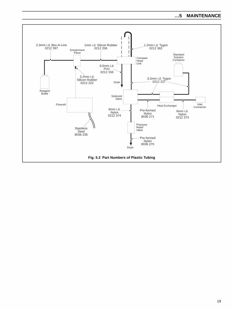
5.4.3 Replacement of Plastic Tubing (Fig. 5.2)Periodically certain sections of plastic tubing requirereplacement due to leakage, blockages, or poor condition. It isgood practice to remove the liquid handling panel every twelvemonths for a complete refurbishment which includes replacingall the plastic tubing. Only the correct size and type of tubeshould be used to fit the pipe connectors – see Section 6 forpart numbers.
Two specific sections of tubing are critical:a) Between the constant head unit and the entrainment ‘T’
piece: Cut 100mm of the 1mm i.d. silicon rubber tube andfit onto the tube connectors. The tube should be taut, anychange to this tube interferes with the flow and self startingcharacteristics.
b) Between the reagent container and entrainment ‘T’ piece;this must be a polyethylene lined tube which has goodchemical resistance to the reagent.
5.4.4 Simple Electronic CheckThe ability of the Pre-amplifier and the Transmitter Unit torespond to an input, can be checked in the following way:a) Disconnect the electrode leads from the terminals in the
junction box on the Sensor Unit door.
b) Connect a milli-volt source to the electrode terminals:negative to ‘Na+’positive to ‘REF’link ‘REF’ to ‘SCR’.
c) Connect a 10kohms resistor across terminals TH1 and TH2 inthe Transmitter Unit to simulate 25°C.
risen above 55°C – checkcause.
5.4.1 Calibration Fail alarmA Calibration Fail condition occurs after a TWO POINTCALIBRATION, when the calculated slope value is less than83%. This could be caused by a number of factors whichshould be investigated. Some indication of the problem can beobtained by displaying “S%” (press STD1 and STD2 together)and noting the slope value.
a) Slope values just below 83%
(i) Check that vapour bubbles are emerging from thebottom of the stainless steel entrainment tube.
(ii) Check condition of reagent solution.
(iii) Reactivate sodium electrode, – see Section 5.1.3. Ifslope value is not improved following a furthercalibration, the electrode should be replaced.
(b) Very low or zero % slope(i) Check the operation of the solenoid valve.
(ii) Check flow of standard solution through flow cell.
(iii) Check level of salt bridge solution in the referenceelectrode.
(iv) Check for open circuit reference electrode bysubstituting with an electrode of known performance.
(v) Check electrical connections in electrode junctionbox and inter-connection cable.
5.4.2 Malfunction of the MonitorMalfunctions of the monitor may produce many effectsfollowing a calibration, some of which
• produce abnormal slope values, see Section 3.2.4,
• display alternates between (reading) and ‘out’. A very largeoffset from the electrode pushes the reading beyond therange of the monitor.
It should always be remembered that any unpredictableproblems may be due to the standard or reagent solutions. Ifany doubts exist regarding the integrity of these solutions, theyshould be replaced with freshly prepared solutions in the earlystages of the fault finding investigations.
The accuracy of the monitor is governed by the condition of allthe solutions involved which can be incorrectly made orcontaminated.
19
…5 MAINTENANCE
Fig. 5.2 Part Numbers of Plastic Tubing
ReagentBottle
EntrainmentPiece
ConstantHeadUnit
StandardSolution
Container
InletConnectorHeat Exchanger
Drain
PressureReliefValve
Flowcell
SolenoidValve
2.3mm i.d. Bev-A-Line0212 397
1mm i.d. Silicon Rubber0212 206
3.2mm i.d. Silicon Rubber
0212 222
9.5mm i.d. PVC
0212 156
6mm i.d.Nylon
0212 374
Pre-formedNylon
8036 270
Pre-formedNylon
8036 271
6mm i.d.Nylon
0212 374
3.2mm i.d. Tygon0212 237
1.2mm i.d. Tygon0212 362
StainlessSteel
8036 235
Drain
20
6 SPARES LIST
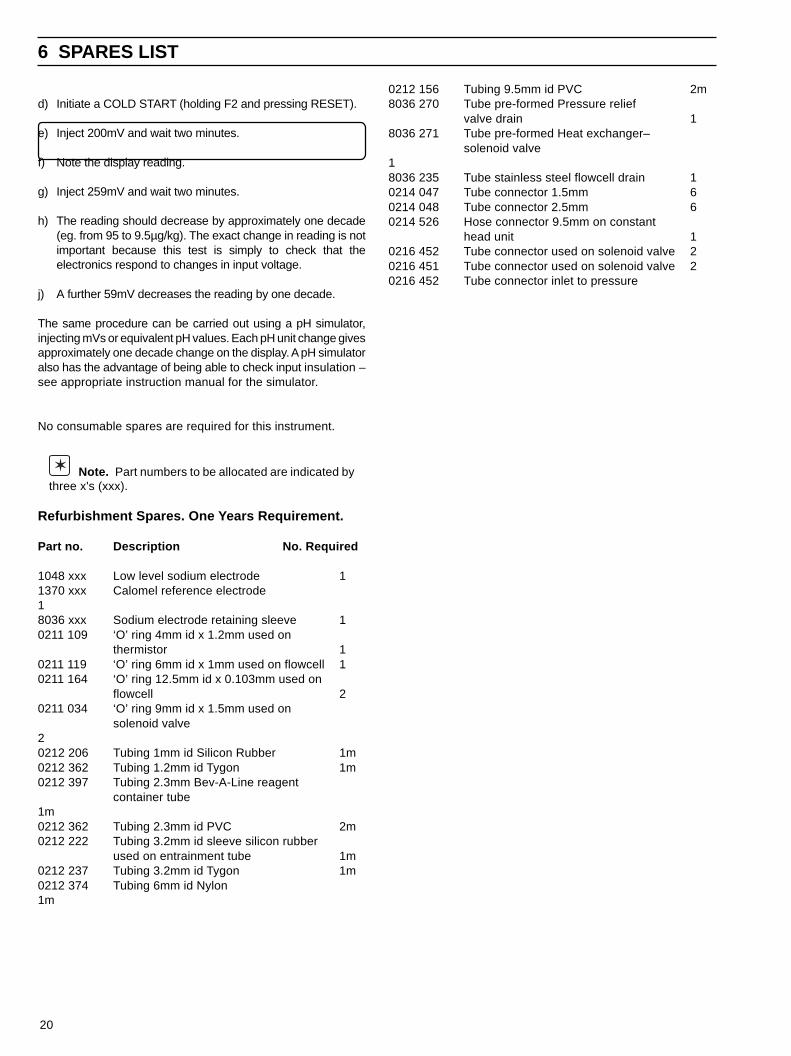
d) Initiate a COLD START (holding F2 and pressing RESET).
e) Inject 200mV and wait two minutes.
f) Note the display reading.
g) Inject 259mV and wait two minutes.
h) The reading should decrease by approximately one decade(eg. from 95 to 9.5µg/kg). The exact change in reading is notimportant because this test is simply to check that theelectronics respond to changes in input voltage.
j) A further 59mV decreases the reading by one decade.
The same procedure can be carried out using a pH simulator,injecting mVs or equivalent pH values. Each pH unit change givesapproximately one decade change on the display. A pH simulatoralso has the advantage of being able to check input insulation –see appropriate instruction manual for the simulator.
No consumable spares are required for this instrument.
Note. Part numbers to be allocated are indicated bythree x's (xxx).
Refurbishment Spares. One Years Requirement.
Part no. Description No. Required
1048 xxx Low level sodium electrode 11370 xxx Calomel reference electrode18036 xxx Sodium electrode retaining sleeve 10211 109 ‘O’ ring 4mm id x 1.2mm used on
thermistor 10211 119 ‘O’ ring 6mm id x 1mm used on flowcell 10211 164 ‘O’ ring 12.5mm id x 0.103mm used on
flowcell 20211 034 ‘O’ ring 9mm id x 1.5mm used on
solenoid valve20212 206 Tubing 1mm id Silicon Rubber 1m0212 362 Tubing 1.2mm id Tygon 1m0212 397 Tubing 2.3mm Bev-A-Line reagent
container tube1m0212 362 Tubing 2.3mm id PVC 2m0212 222 Tubing 3.2mm id sleeve silicon rubber
used on entrainment tube 1m0212 237 Tubing 3.2mm id Tygon 1m0212 374 Tubing 6mm id Nylon1m
0212 156 Tubing 9.5mm id PVC 2m8036 270 Tube pre-formed Pressure relief
valve drain 18036 271 Tube pre-formed Heat exchanger–
solenoid valve18036 235 Tube stainless steel flowcell drain 10214 047 Tube connector 1.5mm 60214 048 Tube connector 2.5mm 60214 526 Hose connector 9.5mm on constant
head unit 10216 452 Tube connector used on solenoid valve 20216 451 Tube connector used on solenoid valve 20216 452 Tube connector inlet to pressure

21
relief valve 10216 453 Tube connector outlet on pressure
relief valve 18061 660 Knurled nut on flowcell 28036 216 Entrainment ‘T’ piece18035 677 Entrainment/earthing tube 18036 247 Reagent container 18063 xxx Reagent container cap assembly 10216 449 Female connector on standard
solution containers 20216 447 Male connector used on calibration
tube assembly 18036 227 Thermistor in flowcell10231 550 Fuse, 2A ceramic 39435 040 Resistor kit of Remote Range Indication 10232 971 Illuminated push switch 20211 683 Thermistor retaining bush 1
Strategic Spares Rarely Requiring Replacement
Part no. Description No. Required
8036 180 Digital circuit board 17835 170 Analogue circuit board 19435 160 Power supply circuit board 18036 050 Pre-amplifier/box assembly 10216 023 Lock and two keys 18036 230 Flowcell complete assy. (less electrodes) 18036 222 Solenoid valve assembly 18036 210 Constant head unit assembly 10216 454 Pressure relief valve 18036 236 Heat exchanger 1Ranges 0.01µg/kg to 1mg/kg or 0.1µg/kg to 10mg/kg
internally selectable.
Accuracy ± 10% of concentration or ± 0.1µg/kgwhichever is the greater (when sampletemperature is within ±5°C of calibrationtemperature).
Reproducibility ±5% of concentration or ±0.1µg/kg–
(whichever is the greater) at constanttemperature.
Response Time 1 to 100µg/kg – less than 4 minutes for90% step change 100 to 1µg/kg – lessthan 6 minutes for 90% step change.
Outputs Two isolated current outputs in therange 0 to 10, 0 to 20 or 4 to 20mA.Maximum impedance 1kΩ. Logarithmic orlinear.
Remote Range Four voltage-free contacts rated 125Va.c.,
Indication 0.4A non-inductive.
External Alarms Two normal or fail-safe, high and lowconcentration alarms.Calibration Mode indication.
Calibration Fail indication.All voltage free 250V, 2A non-inductive.
Battery Backup Issue 6, 8036 180 digital boards: 10 yearsPrior to Issue 6: 4 weeks.
Installation Information
Sample Temperature 5° to 55°C.
Sample Flow 50ml/min to 500ml/min.
Sample Pressure Minimum 0.14 bar (2 psi).
Ambient Temperature 0° to 55°C.
Dimensions ofSensor Unit 300mm wide x 400mm high x
200mm deep.
Mounting forSensor Unit Four Holes
8.5mm diameter230mm horizontal330mm vertical.
Weight ofSensor Unit: 11kg.Connections toSensor Unit: Sample inlet: 6.3mm o.d. compression
fitting.Sample drain:10mm flexible,atmospheric drainElectrical: via gland, cable size 7mm to10.5mm
Max core sizeMains: 32/0.2mm
7 SPECIFICATION …7 SPECIFICATION

22
and is now superseded by the board described in the main textof this manual. The principle difference is the extension of thevolatile memory on the later version. User programmableinformation on the earlier version is only retained for up to 4weeks in power down conditions. Users of monitors with theearlier version board need to undertake additional tasks on adifferent board layout to the information given in the main text.
Setting digital circuit boardFunction switch (SW1)This is situated just below the ALARM 1 push button, and is aseries of eight dual-in-line switches – See Fig. A2. This switchis functionally similar and set as described in the main text.
Battery switch (SW10)This is located at the top of the board – see Fig. A2. This switchis functionally similar and operated as described in the maintext. However, SW10 must be switched to the 'OFF' positionwhen the mains supply is switched off for periods greater than4 weeks, to prevent damage to the Nickel-Cadmium battery.
Other switches and controlsThese are located as shown in Fig. A2, and are functionallysimilar and operated as described in the main text.
Cold startThis event takes place on reinstatement of the mains supplywhen the mains supply has been lost for longer than 4 weeks,*or when the battery switch SW10 has been switched off.Pressing RESET while holding F2 also initiates a COLDSTART.
After a COLD START the data in the volatile memory is lost, sothe microprocessor:
a) Sets Alarm 1 to minimum range valueb) Sets Alarm 2 to full scalec) Reads the default standard solution values on SW1.6d) Sets the slope value to 100% and sets the zero offset to a
default value.
Point d) enables the display to follow changes on the input tothe Transmitter Unit, making electronics testing a simpleoperation.
The display permanently shows ‘888’ after the mains supplyhas been reinstated. This indicates that the battery requiresrecharging. After approximately five minutes, normaloperation can be resumed by pressing the RESET button. ATWO POINT CALIBRATION must now be carried out.
Note. Following a COLD START a full TWO POINTCALIBRATION is required for the instrument to producevalid sodium concentration values.
Warm startThis event takes place when the mains supply has only been
lost for a period of less than 4 weeks , when data held in thevolatile memory is maintained. The instrument returns tonormal operation, maintaining calibration, standard solutionand alarm values previously held.
APPENDIX A
Signal: 24/0.2mm
Dimensions ofTransmitter Unit 300mm wide x 300mm high x 200mm
deep.Mounting forTransmitter Unit Four Holes:
8.5mm diameter230mm horizontal230mm vertical.
Weight ofTransmitter Unit 11kg.
Fig. A1 Part of 8036 180 Digital PCB (Prior to Issue 6)
Battery DigitalDisplay
‘Alarm 1’Button
Function SwitchSW1 1-8
Range Switch
BatterySwitchSW10
OFF — ON
ElectricalConnections Via gland plate to fit glands as required.
Power supplyRequirements 100/110/120/200/220/240V50/
60Hz 100VA.
Power SupplyTolerances Voltage +10% -20%.
Frequency min. 47Hz, maximum 65Hz.
Case Protectionof Transmitter Unit IP55.
Maximum DistanceBetween Sensor& Transmitter Unit 100 metres.
A.1 Transmitter Unit
A.1.1 Previous Type Digital Circuit Board(8036 180 - prior to Issue 6, as marked)
This digital board was fitted to earlier versions of the monitor
23
APPENDIX B APPENDIX B
Note. This refers to 8036-180 digital boards prior toIssue 6. Issue 6 boards retain the memory for 10 years.
Sample temperatureThe temperature of the sample water is continuouslymonitored by means of a thermistor housed in the flow cell.
If the temperature of the sample rises above 55°C, the displayshows ‘hot’. After 30 minutes the temperature is againmeasured. This procedure repeats until the sampletemperature is less than 55°C; the monitor then returns to the‘RUN’ mode.
A.2 Shut - Down Procedure
A.2.1 Transmitter unitUndertake the procedure as follows:
a) Open the unit and gain access to the digital board byreleasing the 4 plastic fasteners securing the front panel.
b) Set the battery switch (SW 10) to ‘OFF’.
c) Replace the front panel and secure with the fasteners.
A.3 Spares ListSubstitute the new Digital Circuit Board complete ( PartNumber 9435 180) as a replacement for the previous type.
24
APPENDIX C
Check the new board against Section 3.2.3 and follow theprocedures given in the main text in Section 2.4 and Section2.6.
Di-isopropylamine Reagent
Warning. Di-isopropylamine is an extremelyinflamable, colourless liquid. It is irritating to the eyes,respiratory system and skin. It should be handled withcare at all times. The following points should be noted:
• Avoid breathing vapour and avoid contact with skin andeyes.
• Work under a fume hood, wearing rubber gloves andeye protection.
• In the event of a fire, extinguish with water spray, foam,dry powder or carbon dioxide.
• If a spillage occurs, shut off all possible sources ofignition, and instruct others to keep at a safe distance.Mop up spillage with plenty of water, diluting greatly.Ventilate the area well to evaporate any remaining liquidand dispel vapour.
• Effluent from the monitor contains di-isopropylamine.Contact with the effluent should also be avoided.
Place approximately 500ml of concentrated reagent grade di-isopropylamine [(CH3)2CH]2NH in the reagent container andapply the cap tightly.
C1 Calibration for High Sodium ConcentrationsIn some applications it has been observed that good accuracymay not be obtained at high sodium concentrations if themonitor has been running for long periods at low concentrationlevels. The modifications detailed in this appendix explain howto overcome this.
Warning. Sodium fluoride is toxic. Avaiod inhalingthe dust and prevent contact with skin and eyes. Wear adust mask, rubber gloves and eye protection.
The modifications comprise:• a 3-port solenoid valve in the delivery tube from the
reagent container;• a change in standard solution composition;• modified software in the transmitter unit.
C2 The Calibration ProcedureFor the first five minutes of the procedure the solenoid valve isenergised, under the control of the software, such that thereagent vapour is blocked and air is introduced.
The standard solution, which is an acidified solution of sodiumfluoride, passes through the flowcell and imparts a mild etch tothe sodium electrode. The valve then closes and reagentvapour addition returns. (The alkaline reagent vapour issufficient to overcome the weak acidity of the standardsolution.)
The monitor then calibrates as normal for 15 minutes beforereturning to sample or secondary standard, as appropriate.
This procedure occurs during both normal and automaticcalibration modes.
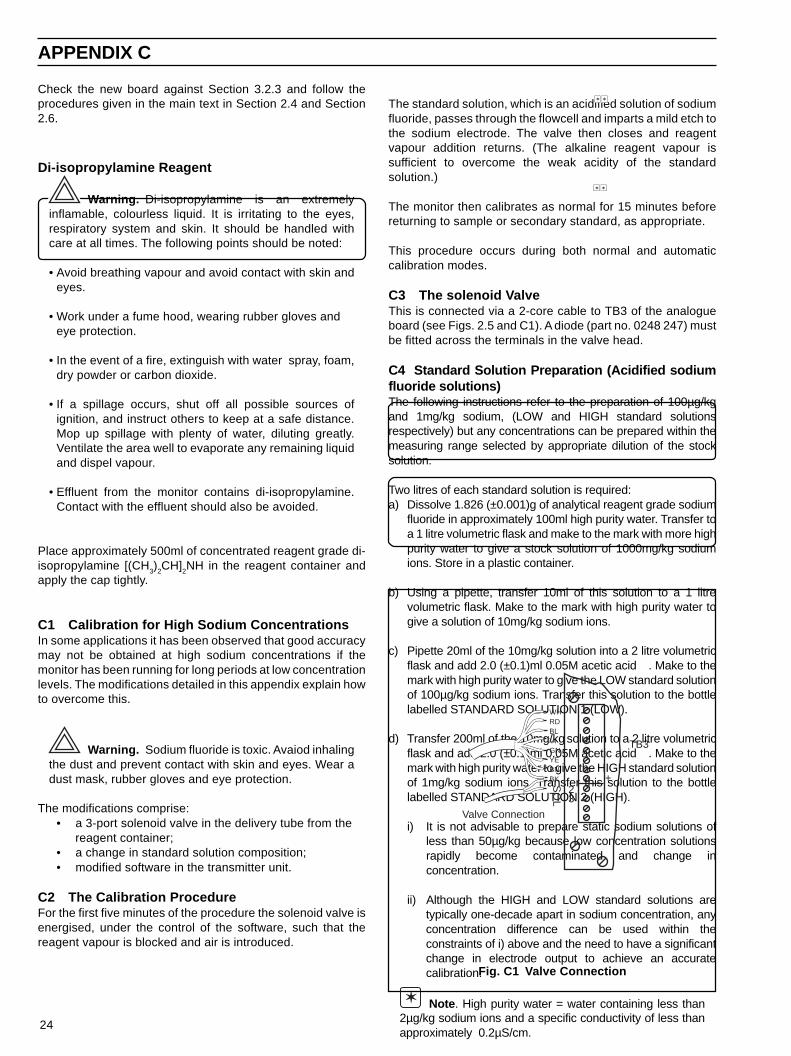
C3 The solenoid ValveThis is connected via a 2-core cable to TB3 of the analogueboard (see Figs. 2.5 and C1). A diode (part no. 0248 247) mustbe fitted across the terminals in the valve head.
C4 Standard Solution Preparation (Acidified sodiumfluoride solutions)The following instructions refer to the preparation of 100µg/kgand 1mg/kg sodium, (LOW and HIGH standard solutionsrespectively) but any concentrations can be prepared within themeasuring range selected by appropriate dilution of the stocksolution.
Two litres of each standard solution is required:a) Dissolve 1.826 (±0.001)g of analytical reagent grade sodium
fluoride in approximately 100ml high purity water. Transfer toa 1 litre volumetric flask and make to the mark with more highpurity water to give a stock solution of 1000mg/kg sodiumions. Store in a plastic container.
b) Using a pipette, transfer 10ml of this solution to a 1 litrevolumetric flask. Make to the mark with high purity water togive a solution of 10mg/kg sodium ions.
c) Pipette 20ml of the 10mg/kg solution into a 2 litre volumetricflask and add 2.0 (±0.1)ml 0.05M acetic acid . Make to themark with high purity water to give the LOW standard solutionof 100µg/kg sodium ions. Transfer this solution to the bottlelabelled STANDARD SOLUTION 1 (LOW).
d) Transfer 200ml of the 10mg/kg solution to a 2 litre volumetricflask and add 2.0 (±0.1)ml 0.05M acetic acid . Make to themark with high purity water to give the HIGH standard solutionof 1mg/kg sodium ions. Transfer this solution to the bottlelabelled STANDARD SOLUTION 2 (HIGH).
i) It is not advisable to prepare static sodium solutions ofless than 50µg/kg because low concentration solutionsrapidly become contaminated and change inconcentration.
ii) Although the HIGH and LOW standard solutions aretypically one-decade apart in sodium concentration, anyconcentration difference can be used within theconstraints of i) above and the need to have a significantchange in electrode output to achieve an accuratecalibration.
Note . High purity water = water containing less than2µg/kg sodium ions and a specific conductivity of less thanapproximately 0.2µS/cm.
TB3
WHRDBLVIGNYEBNBK
Valve Connection
23
+SO
L
Fig. C1 Valve Connection

PRODUCTS & CUSTOMER SUPPORT
A Comprehensive Instrumentation Range
Analytical Instrumentation• Trans mitters
On-line pH, conductivity, and dissolved oxygentransmitters and associated sensing systems.
• SensorspH, redox, selective ion, conductivity and dissolvedoxygen.
• Laboratory InstrumentationpH and dissolved oxygen meters and associatedsensors.
• Water AnalyzersFor water quality monitoring in environmental, powergeneration and general industrial applications including:pH, conductivity, ammonia, nitrate, phosphate, silica,sodium, chloride, fluoride, dissolved oxygen andhydrazine.
• Gas AnalyzersZirconia, paramagnetic, infrared, thermal conductivity.
Controllers & Recorders• Controllers
Digital display, electronic, pneumatic. Discrete single-loop and multi-loop controllers which can be linked to acommon display station, process computer or personalcomputer.
• RecordersCircular and strip-chart types (single and multi-point) fortemperature, pressure, flow and many other processmeasurements.
Electronic Transmitters• Smart & Analog Transmitters
For draft, differential, gauge and absolute pressuremeasurement. Also, liquid level and temperature
• I to P Converters and Field Indicators
Flow Metering• Magnetic Flowmeters
Electromagnetic, insertion type probes and watermeters.
• Turbine Flowmeters
• Wedge Flow Elements
• Mass Flow MetersTransmitters, sensors, controllers and batch/displayunits.
Level Control• Submersible, Capacitance & Conductivity.
Pneumatic Instrumentation• Transmitters
• Indicating Controllers
• Recording Controllers
Customer Support
ABB Kent-Taylor provides a comprehensive after salesservice via a Worldwide Service Organization. Contact one ofthe following offices for details on your nearest Service andRepair Centre.
United KingdomABB Kent-Taylor LimitedTel: (01480) 470781Fax: (01480) 470787
United States of AmericaABB Kent-Taylor Inc.Tel: (716) 2926050Fax: (716) 2736207
ItalyABB Kent-Taylor SpATel: (0344) 58111Fax: (0344) 56278
Client Warranty
Prior to installation, the equipment referred to in this manualmust be stored in a clean, dry, atmospherically controlledenvironment, in accordance with the Company's publishedspecification. Periodic checks must be made on the equipment'scondition.
In the event of a failure under warranty, the followingdocumentation must be provided as substantiation:
1. A listing evidencing process operation and alarm logs at timeof failure.
2. Copies of operating and maintenance records relating to thealleged faulty unit.

The Company's policy is one of continuous productimprovement and the right is reserved to modify theinformation contained herein without notice.
© July 1995 ABB Kent-Taylor Printed in U.K.
ABB Kent-Taylor Ltd.St. Neots,Cambs.England, PE19 3EUTel: (01480) 475321Fax: (01480) 217948
ABB Kent-Taylor Inc.PO Box 20550, RochesterNew York 14602-0550USATel: (716) 292 6050Fax: (716) 273 6207
ABB Kent-Taylor SpA22016 LennoComoItalyTel: (0344) 58111Fax: (0344) 56278
IM/8
035-
PM
PIs
sue
B
ABB Kent-Taylor Ltd.Analytical & Flow GroupStonehouse, Glos.England, GL10 3TATel: (01453) 826661Fax: (01453) 826358