abb sace emax pr122
TRANSCRIPT

Technical catalogue - Preliminary
SACE Tmax VF and Emax VFLow voltage circuit-breakers for variable frequency applications

Main characteristics 1
The ranges 2
Installation 3
Protection trip units and trip curves 4
Accessories 5
Overall dimensions 6
Circuit diagrams 7
Ordering codes 8
1SDC007904D0201
SACE Tmax VF and SACE Emax VF
2
SACE Tmax VF and SACE Emax VF Low Voltage circuit-breakers for applications at variable frequency
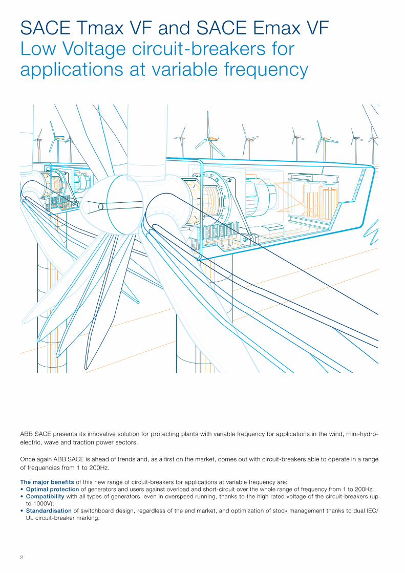
ABB SACE presents its innovative solution for protecting plants with variable frequency for applications in the wind, mini-hydro-electric, wave and traction power sectors. Once again ABB SACE is ahead of trends and, as a first on the market, comes out with circuit-breakers able to operate in a range of frequencies from 1 to 200Hz.
The major benefits of this new range of circuit-breakers for applications at variable frequency are:• Optimal protection of generators and users against overload and short-circuit over the whole range of frequency from 1 to 200Hz;• Compatibility with all types of generators, even in overspeed running, thanks to the high rated voltage of the circuit-breakers (up
to 1000V);• Standardisation of switchboard design, regardless of the end market, and optimization of stock management thanks to dual IEC/
UL circuit-breaker marking.

3
From the experience gained in designing air and moulded-case circuit-breakers, the new range of SACE Tmax VF and SACE Emax VF circuit-breakers has come into being for applications at variable frequency. The new range of SACE Tmax VF and SACE Emax VF circuit-breakers is the ideal solution for applications at variable frequency thanks to:• New electronic trip units and optimised current sensors, along with ABB SACE technologies, able to
ensure a high level of accuracy and precision of the protections when the frequency varies; • Arc-breaking chambers and main contacts developed to ensure high breaking capacities over the
whole frequency range;• Circuit-breaker design and use of high-performing materials allowing operation up to 1000V;• Extensive testing and periodic follow-ups with the certifying bodies make certification of the circuit-
breaker according to the International IEC60947, UL1066 and UL489 Standards possible.
ABB has always paid special attention to renewable energy generation, constantly collaborating alongside the major wind turbine manufacturers, sensing the need ahead of others to protect plants with variable frequency.
Pantone Process Cyan PCPantone solid to process 2975 PC
Black
Colors
RAL 7012
ABB SACE SpA
Curzio Cucinotta 10/11/2010
Titolo: Loghi SACE VFT e SACE LTT
-40°CLow Temperature TechnologySACE R
Variable Frequency Technology
SACE R
10,0
00 m
m
50,000 mm 50,000 mm
14,0
00 m
m
54,000 mm 54,000 mm
-40°CLow Temperature TechnologySACE R
Variable Frequency Technology
SACE R

1/11SDC007904D0201
Content
Distinguishing Features of the series................................................................................ 1/2
Main characteristics
1/21SDC007904D0201
Main characteristicsDistinguishing.Features.of.the.Series
Performances–. Operating.frequency.from.1.up.to.200Hz–. Rated.uninterrupted.current.Iu.from.800A.up.to.5000A–. Rated.service.voltage.of.1000V.–. High.breaking.capacity.over.the.whole.range.of.frequency
Operating FrequencyBy.means.of.SACE.VFT.(Variable.Frequency.Technology).the.Tmax.VF.and.Emax.VF.circuit-breakers.can.operate.in.an.extended.range.of.frequency:.from.1Hz.up.to.200Hz..
The.new.family.of.trip.units.together.with.optimized.current.sensors.ensures.high.precision.of.the.protection.functions.for.an.extended.frequency.range..Whilst. improved.arcing.chamber.and.main.contacts.guarantee.high.performances.in.terms.of.breaking.capacity.over.the.whole.frequency.range.
The. overcurrent. protection. for. variable. frequency. installations. uses. four. types. of. trip. units.according.to.the.rated.current.and.frequency.range:–. Thermomagnetic:.for.low.frequency.(1…60Hz).up.to.800A–. PR222/VF:.for.high.frequency.(20…200Hz).up.to.800A–. PR122/VF:.for.low.frequency.(1..60Hz).up.to.2500A–. PR111/VF:.for.high.frequency.(20…200Hz).up.to.5000A
Operating temperatureThe. Tmax. VF. and. Emax. VF. circuit-breakers. can. be. used. in. ambient. conditions. where. air.temperature.varies.between.-25.°C.and.+70.°C.(-13°F.and.+158.°F).
Pantone Process Cyan PCPantone solid to process 2975 PC
Black
Colors
RAL 7012
ABB SACE SpA
Curzio Cucinotta 10/11/2010
Titolo: Loghi SACE VFT e SACE LTT
-40°CLow Temperature TechnologySACE R
Variable Frequency Technology
SACE R
10,0
00 m
m
50,000 mm 50,000 mm
14,0
00 m
m
54,000 mm 54,000 mm
-40°CLow Temperature TechnologySACE R
Variable Frequency Technology
SACE R
1/31SDC007904D0201
Compliance with StandardsSACE.Tmax.VF.and.SACE.Emax.VF.circuit-breakers.and. their. accessories.conform. to. the.International. IEC.60947,.EN.60947. (harmonized. in.30.CENELEC.countries),.CEI.EN.60947.and.IEC.61000.Standards,.and.comply.with.the.following.EC.directives:–.“Low.Voltage.Directive”.(LVD).no.73/23.EEC–.“Electromagnetic.Compatibility.Directive”.(EMC).nr..89/336.EEC.
Furthermore,. the. Tmax. VF. automatic. circuit-breakers. and. their. electrical. accessories. also.conform.to. the.UL.489. (Underwriters.Laboratories. Incorporated),.while. the.SACE.Emax.VF.circuit-breakers.for.high.frequency.applications.and.switch-disconnector.are.UL.1066.certified,.allowing.their.use.in.UL.1558.switchgear.and.UL.891.Low.Voltage.switchboards.
Certification.of.conformity.with.the.aforementioned.product.Standards.is.carried.out.in.compliance.with.European.Standard.EN.45011.by.the.Italian.certification.body.ACAE.(Associazione.per.la.Certificazione.delle.Apparecchiature.Elettriche.–.Association. for.Certification.of.Electrical.Apparatus),.recognized.by.the.European.LOVAG.organization.(Low.Voltage.Agreement.Group),.and.by.the.Swedish.SEMKO.certification.organization,.recognized.by.the.International.IECEE.organization.
Resistance to shock and vibrationThe. circuit-breakers. are. unaffected. by. vibrations. generated. mechanically. or. due. to.electromagnetic.effects,.in.compliance.with.the.IEC.60068-2-6.Standards.and.the.regulations.of.the.major.classification.organizations:–.RINA.(Italian.Naval.Register)–.Det.Norske.Veritas–.Bureau.Veritas–.Lloyd’s.register.of.shipping–.Germanischer.Lloyd–.ABS.(American.Bureau.of.Shipping)–.RMRS.(Russian.Maritime.Register.of.Shipping)
Note: Contact ABB SACE for a list of approved types of circuit-breakers, approved performance data and the corresponding validity
1/41SDC007904D0201
Main characteristicsDistinguishing.Features.of.the.Series
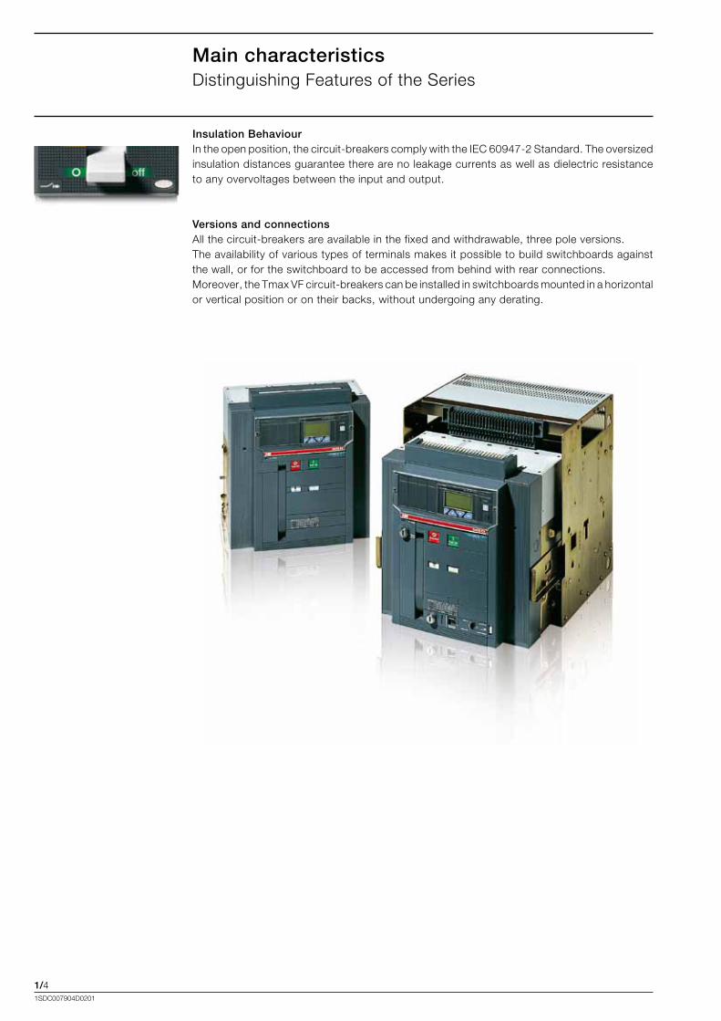
Insulation BehaviourIn.the.open.position,.the.circuit-breakers.comply.with.the.IEC.60947-2.Standard..The.oversized.insulation.distances.guarantee.there.are.no.leakage.currents.as.well.as.dielectric.resistance.to.any.overvoltages.between.the.input.and.output.
Versions and connectionsAll.the.circuit-breakers.are.available.in.the.fixed.and.withdrawable,.three.pole.versions.The.availability.of.various.types.of.terminals.makes.it.possible.to.build.switchboards.against.the.wall,.or.for.the.switchboard.to.be.accessed.from.behind.with.rear.connections.Moreover,.the.Tmax.VF.circuit-breakers.can.be.installed.in.switchboards.mounted.in.a.horizontal.or.vertical.position.or.on.their.backs,.without.undergoing.any.derating.
2/11SDC007904D0201
Content
Automatic circuit-breaker for Low Frequency applications........................................... 2/2
Automatic circuit-breaker for High Frequency applications.......................................... 2/3
Switch disconnector for variable frequency applications.............................................. 2/4
The ranges
2/21SDC007904D0201
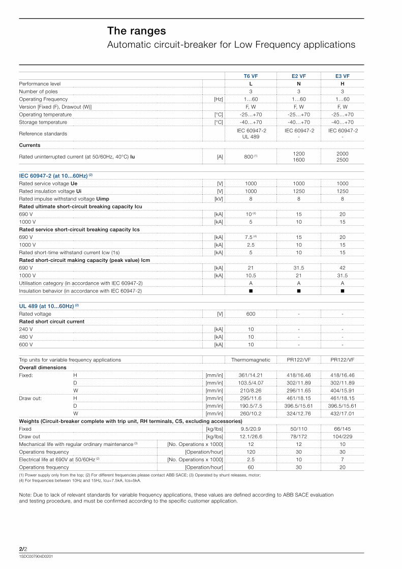
The rangesAutomatic.circuit-breaker.for.Low.Frequency.applications
T6 VF E2 VF E3 VF
Performance.level L N H
Number.of.poles 3 3 3
Operating.Frequency .[Hz] 1…60 1…60 1…60
Version.[Fixed.(F),.Drawout.(W)] F,.W F,.W F,.W
Operating.temperature .[°C] -25…+70 -25…+70 -25…+70
Storage.temperature. .[°C] -40…+70 -40…+70 -40…+70
Reference.standards..IEC.60947-2
UL.489.IEC.60947-2
-.IEC.60947-2
-
Currents
Rated.uninterrupted.current.(at.50/60Hz,.40°C).Iu .[A] 800.(1) 12001600
20002500
IEC 60947-2 (at 10...60Hz) (2)
Rated.service.voltage.Ue [V] 1000 1000 1000
Rated.insulation.voltage.Ui. [V] 1000 1250 1250
Rated.impulse.withstand.voltage.Uimp. [kV] 8 8 8
Rated ultimate short-circuit breaking capacity Icu
690.V. [kA] 10.(4) 15 20
1000.V. [kA] 5 10 15
Rated service short-circuit breaking capacity Ics
690.V. [kA] 7.5.(4) 15 20
1000.V. [kA] 2.5 10 15
Rated.short-time.withstand.current.Icw.(1s) [kA] 5 10 15
Rated short-circuit making capacity (peak value) Icm
690.V. [kA] 21 31.5 42
1000.V. [kA] 10.5 21 31.5
Utilisation.category.(in.accordance.with.IEC.60947-2) A A A
Insulation.behavior.(in.accordance.with.IEC.60947-2) n n n
UL 489 (at 10...60Hz) (2)
Rated.voltage .[V] 600 - -
Rated short circuit current
240.V .[kA] 10 - -
480.V.. .[kA] 10 - -
600.V.. .[kA] 10 - -
Trip.units.for.variable.frequency.applications Thermomagnetic PR122/VF PR122/VF
Overall dimensions
Fixed: H [mm/in] 361/14.21 418/16.46 418/16.46
D [mm/in] 103.5/4.07 302/11.89 302/11.89
W [mm/in] 210/8.26 296/11.65 404/15.91
Draw.out: H [mm/in] 295/11.6 461/18.15 461/18.15
D [mm/in] 190.5/7.5 396.5/15.61 396.5/15.61
W [mm/in] 260/10.2 324/12.76 432/17.01
Weights (Circuit-breaker complete with trip unit, RH terminals, CS, excluding accessories)
Fixed [kg/lbs] 9.5/20.9 50/110 66/145
Draw.out.. [kg/lbs] 12.1/26.6 78/172 104/229
Mechanical.life.with.regular.ordinary.maintenance.(3) [No..Operations.x.1000] 12 12 10
Operations.frequency [Operation/hour] 120 30 30
Electrical.life.at.690V.at.50/60Hz.(2) [No..Operations.x.1000] 2.5 10 7
Operations.frequency [Operation/hour] 60 30 20(1).Power.supply.only.from.the.top;.(2).For.different.frequencies.please.contact.ABB.SACE;.(3).Operated.by.shunt.releases,.motor;.(4).For.frequencies.between.10Hz.and.15Hz,.Icu=7.5kA,.Ics=5kA.
Note:.Due.to.lack.of.relevant.standards.for.variable.frequency.applications,.these.values.are.defined.according.to.ABB.SACE.evaluation.and.testing.procedure,.and.must.be.confirmed.according.to.the.specific.customer.application.

2/31SDC007904D0201
The rangesAutomatic.circuit-breaker.for.High.Frequency.applications
T6 VF E2 VF E3 VF E4 VF E6 VF
Performance.level L N H H H
Number.of.poles 3 3 3 3 3
Operating.Frequency .[Hz] 20…200 20…200 20…200 20…200 20…200
Version.[Fixed.(F),.Drawout.(W)] F,.W F,.W F,.W F,.W F,.W
Operating.temperature [°C] -25…+70 -25…+70 -25…+70 -25…+70 -25…+70
Storage.temperature [°C] -40…+70 -40…+70 -40…+70 -40…+70 -40…+70
Reference.standards.IEC.60947-2
UL.489.IEC.60947-2
UL.1066.IEC.60947-2
UL.1066.IEC.60947-2
UL.1066.IEC.60947-2
UL.1066
Currents
Rated.uninterrupted.current.(at.50/60Hz,.40°C).Iu .[A] 800.(1) 12001600
20002500
3600 5000
IEC 60947-2Rated.service.voltage.Ue .[V] 1000 1000 1000 1000 1000
Rated.insulation.voltage.Ui.. .[V] 1000 1250 1250 1250 1250
Rated.impulse.withstand.voltage.Uimp.. .[kV] 8 12 12 12 12
Rated ultimate short-circuit breaking capacity Icu
690.V. [kA] 10 15 20 25 25
1000.V.. [kA] 5 10 15 20 20
Rated service short-circuit breaking capacity Ics
690.V.. [kA] 7.5 15 20 25 25
1000.V. [kA] 2.5 10 15 20 20
Rated.short-time.withstand.current.Icw.(1s).. [kA] 5 10 15 20 20
Rated short-circuit making capacity (peak value) Icm
690.V.. [kA] 21 31.5 42 52.5 52.5
1000.V. [kA] 10.5 21 31.5 42 42
Utilisation.category.(in.accordance.with.IEC.60947-2) A A A A A
Insulation.behavior.(in.accordance.with.IEC.60947-2) n n n n n
UL 489 and 1066 UL489 UL1066
Rated.voltage .[V] 600 600 600 600 600
Rated short circuit current
240.V [kA] 10 15 20 25 25
480.V.. [kA] 10 15 20 25 25
600.V. [kA] 10 15 20 25 25
Rated.short.time.current.. [kA] - 15 20 25 25
Trip.units.for.variable.frequency.applications PR222/VF PR111/VF PR111/VF PR111/VF PR111/VF
Overall dimensions
Fixed: H .[mm/in] 361/14.21 418/16.46 418/16.46 418/16.46 418/16.46
D.. .[mm/in] 103.5/4.07 302/11.89 302/11.89 302/11.89 302/11.89
W.. .[mm/in] 210/8.26 296/11.65 404/15.91 566/22.28 782/30.79
Draw.out: H.. .[mm/in] 295/11.6 461/18.15 461/18.15 461/18.15 461/18.15
D... .[mm/in] 190.5/7.5 396.5/15.61 396.5/15.61 396.5/15.61 396.5/15.61
W.. .[mm/in] 260/10.2 324/12.76 432/17.01 594/23.39 810/31.89
Weights (Circuit-breaker complete with trip unit, RH terminals, CS, excluding accessories)
Fixed [kg/lbs] 9.5/20.9 50/110 66/145 97/214 140/308
Draw.out [kg/lbs] 12.1/26.6 78/172 104/229 147/324 210/463
Mechanical.life.with.regular.ordinary.maintenance.(2) [No..Operations.x.1000] 12 12 10 8 8
Operations.frequency [Operation/hour] 120 30 30 30 30
Electrical.life.at.690V.at.50/60Hz.(3) [No..Operations.x.1000] 2.5 10 7 4 2
Operations.frequency [Operation/hour] 60 30 20 10 10(1).Power.supply.only.from.the.top;.(2).Operated.by.shunt.releases,.motor;.(3).For.different.frequencies.please.contact.ABB.SACE.
Note:.Due.to.lack.of.relevant.standards.for.variable.frequency.applications,.these.values.are.defined.according.to.ABB.SACE.evaluation.and.testing.procedure,.and.must.be.confirmed.according.to.the.specific.customer.application.
2/41SDC007904D0201
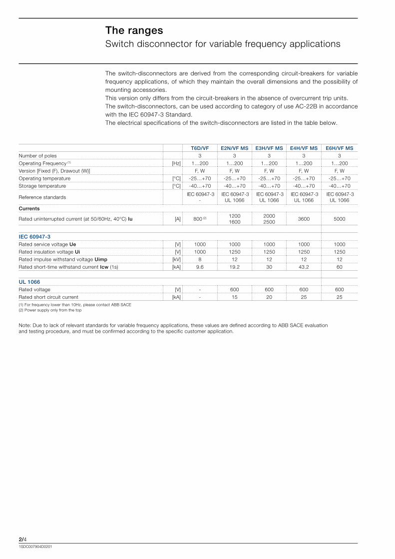
The rangesSwitch.disconnector.for.variable.frequency.applications
The. switch-disconnectors. are. derived. from. the. corresponding. circuit-breakers. for. variable.frequency.applications,.of.which.they.maintain.the.overall.dimensions.and.the.possibility.of.mounting.accessories.This.version.only.differs.from.the.circuit-breakers.in.the.absence.of.overcurrent.trip.units.The.switch-disconnectors,.can.be.used.according.to.category.of.use.AC-22B.in.accordance.with.the.IEC.60947-3.Standard..The.electrical.specifications.of.the.switch-disconnectors.are.listed.in.the.table.below.
T6D/VF E2N/VF MS E3H/VF MS E4H/VF MS E6H/VF MS
Number.of.poles 3 3 3 3 3
Operating.Frequency.(1) .[Hz] 1…200 1…200 1…200 1…200 1…200
Version.[Fixed.(F),.Drawout.(W)] F,.W F,.W F,.W F,.W F,.W
Operating.temperature [°C] -25…+70 -25…+70 -25…+70 -25…+70 -25…+70
Storage.temperature [°C] -40…+70 -40…+70 -40…+70 -40…+70 -40…+70
Reference.standards.IEC.60947-3
-.IEC.60947-3
UL.1066.IEC.60947-3
UL.1066.IEC.60947-3
UL.1066.IEC.60947-3
UL.1066
Currents
Rated.uninterrupted.current.(at.50/60Hz,.40°C).Iu .[A] 800.(2). 12001600
20002500
3600 5000
IEC 60947-3Rated.service.voltage.Ue .[V] 1000 1000 1000 1000 1000
Rated.insulation.voltage.Ui.. .[V] 1000 1250 1250 1250 1250
Rated.impulse.withstand.voltage.Uimp.. .[kV] 8 12 12 12 12
Rated.short-time.withstand.current.Icw.(1s) .[kA] 9.6 19.2 30 43.2 60
UL 1066Rated.voltage .[V] - 600 600 600 600
Rated.short.circuit.current.. [kA] - 15 20 25 25(1).For.frequency.lower.than.10Hz,.please.contact.ABB.SACE.(2).Power.supply.only.from.the.top
Note:.Due.to.lack.of.relevant.standards.for.variable.frequency.applications,.these.values.are.defined.according.to.ABB.SACE.evaluation.and.testing.procedure,.and.must.be.confirmed.according.to.the.specific.customer.application.
3/11SDC007904D0201
Content
Applications........................................................................................................................... 3/2
Frequency performances
. Changing.the.rated.uninterrupted.current.in.relation.to.the.frequency......................... 3/4
Temperature performances
. Changing.the.rated.uninterrupted.current.in.relation.to.the.temperature...................... 3/5
Derating at different altitudes............................................................................................. 3/6
Installation
3/21SDC007904D0201
InstallationApplications.of.the.circuit-breaker
The.circuit.breakers.for.variable.frequency.applications.is.typically.installed.in.wind.turbine.full.converter.concepts..On.these.turbines,.the.converter.decouples.the.synchronous.(permanent.magnet).and.asynchronous.generator.and.the.mechanical.drivetrain.from.the.grid..The.power.generated.in.a.wide.range.of.frequencies.flows.through.the.converter.to.the.grid.The.main.purposes.of.the.circuit.breaker.installed.in.the.variable.frequency.side.are:•.protection.against.fault.involving.the.inverter.or.the.connections.between.the.generator.and.
the.inverter.(e.g..cable.section);•.backup.of.the.embedded.inverter.protection.functions.to.give.a.redundancy.disconnection.
of.the.generator.in.case.of.fault;•. safe.insulation.of.the.electric.power.source.for.normal.operation.and.maintenance.activities.
(circuit.breaker.controlled.by.the.inverter.automation.system)..
Application.examples:
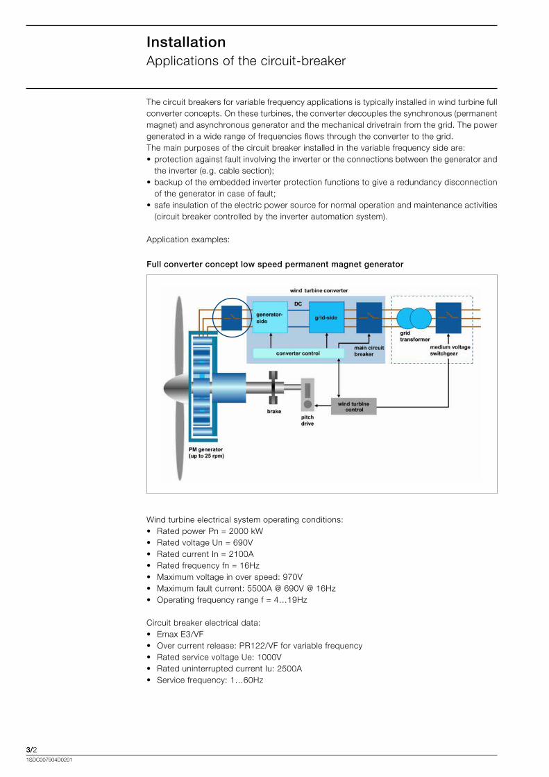
Full converter concept low speed permanent magnet generator
Wind.turbine.electrical.system.operating.conditions:•. Rated.power.Pn.=.2000.kW•. Rated.voltage.Un.=.690V•. Rated.current.In.=.2100A•. Rated.frequency.fn.=.16Hz•. Maximum.voltage.in.over.speed:.970V•. Maximum.fault.current:[email protected][email protected]•. Operating.frequency.range.f.=.4…19Hz
Circuit.breaker.electrical.data:•. Emax.E3/VF•. Over.current.release:.PR122/VF.for.variable.frequency•. Rated.service.voltage.Ue:.1000V•. Rated.uninterrupted.current.Iu:.2500A•. Service.frequency:.1…60Hz
3/31SDC007904D0201
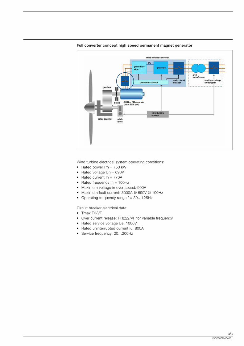
Full converter concept high speed permanent magnet generator
Wind.turbine.electrical.system.operating.conditions:•. Rated.power.Pn.=.750.kW•. Rated.voltage.Un.=.690V•. Rated.current.In.=.770A•. Rated.frequency.fn.=.100Hz•. Maximum.voltage.in.over.speed:.900V•. Maximum.fault.current:[email protected][email protected]•. Operating.frequency.range.f.=.30…125Hz
Circuit.breaker.electrical.data:•. Tmax.T6/VF•. Over.current.release:.PR222/VF.for.variable.frequency•. Rated.service.voltage.Ue:.1000V•. Rated.uninterrupted.current.Iu:.800A•. Service.frequency:.20…200Hz
3/41SDC007904D0201
InstallationFrequency.performances
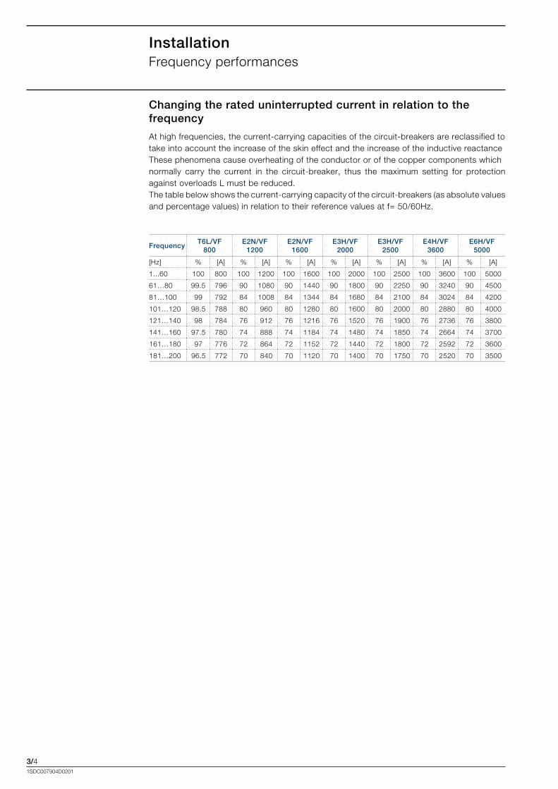
Changing the rated uninterrupted current in relation to the frequency
At.high.frequencies,.the.current-carrying.capacities.of.the.circuit-breakers.are.reclassified.to.take.into.account.the.increase.of.the.skin.effect.and.the.increase.of.the.inductive.reactance...These.phenomena.cause.overheating.of.the.conductor.or.of.the.copper.components.which.normally. carry. the. current. in. the. circuit-breaker,. thus. the. maximum. setting. for. protection.against.overloads.L.must.be.reduced.The.table.below.shows.the.current-carrying.capacity.of.the.circuit-breakers.(as.absolute.values.and.percentage.values).in.relation.to.their.reference.values.at.f=.50/60Hz.
FrequencyT6L/VF
800E2N/VF
1200E2N/VF
1600E3H/VF
2000E3H/VF
2500E4H/VF
3600E6H/VF
5000
[Hz] % [A] % [A] % [A] % [A] % [A] % [A] % [A]
1...60 100 800 100 1200 100 1600 100 2000 100 2500 100 3600 100 5000
61…80 99.5 796 90 1080 90 1440 90 1800 90 2250 90 3240 90 4500
81…100 99 792 84 1008 84 1344 84 1680 84 2100 84 3024 84 4200
101…120 98.5 788 80 960 80 1280 80 1600 80 2000 80 2880 80 4000
121…140 98 784 76 912 76 1216 76 1520 76 1900 76 2736 76 3800
141…160 97.5 780 74 888 74 1184 74 1480 74 1850 74 2664 74 3700
161…180 97 776 72 864 72 1152 72 1440 72 1800 72 2592 72 3600
181…200 96.5 772 70 840 70 1120 70 1400 70 1750 70 2520 70 3500
3/51SDC007904D0201
InstallationTemperature.performances
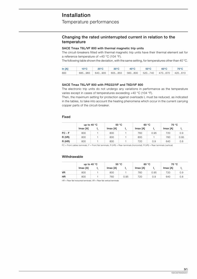
Changing the rated uninterrupted current in relation to the temperature
In [A] 10°C 20°C 30°C 40°C 50°C 60°C 70°C
800 685...965 640...905. 605...855 560...800 520...740 470...670 420...610
Fixed
Withdrawable
up to 40 °C 50 °C 60 °C 70 °C
Imax [A] I1 Imax [A] I1 Imax [A] I1 Imax [A] I1
FC - F 800 1 800 1 760 0.95 720 0.9
R (VR) 800 1 800 1 800 1 760 0.95
R (HR) 800 1 800 1 720 0.9 640 0.8
FC.=.Front.cables.terminals;.F.=.Front.flat.terminals;.R.(HR).=.Rear.terminals.(horizontal);.R.(VR).=.Rear.terminals.(vertical).
up to 40 °C 50 °C 60 °C 70 °C
Imax [A] I1 Imax [A] I1 Imax [A] I1 Imax [A] I1
VR 800 1 800 1 760 0.95 720 0.9
HR 800 1 760 0.95 720 0.9 640 0.8
HR.=.Rear.flat.horizontal.terminals;.VR.=.Rear.flat.vertical.terminals
SACE Tmax T6L/VF 800 with thermal magnetic trip unitsThe.circuit-breakers.fitted.with.thermal.magnetic.trip.units.have.their.thermal.element.set.for.a.reference.temperature.of.+40.°C.(104.°F)..The.following.table.shown.the.deviation,.with.the.same.setting,.for.temperatures.other.than.40.°C.
SACE Tmax T6L/VF 800 with PR222/VF and T6D/VF 800The.electronic. trip.units.do.not.undergo.any. variations. in.performance.as. the. temperature.varies.except.in.cases.of.temperatures.exceeding.+40.°C.(104.°F)..Then,.the.maximum.setting.for.protection.against.overloads.L.must.be.reduced,.as.indicated.in.the.tables,.to.take.into.account.the.heating.phenomena.which.occur.in.the.current.carrying.copper.parts.of.the.circuit-breaker.
3/61SDC007904D0201
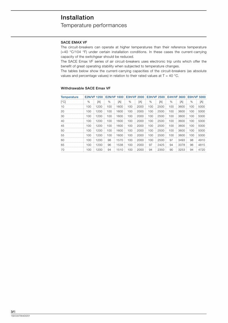
SACE EMAX VFThe. circuit-breakers. can. operate. at. higher. temperatures. than. their. reference. temperature........(+40. °C/104. °F). under. certain. installation. conditions.. In. these. cases. the. current-carrying.capacity.of.the.switchgear.should.be.reduced.The. SACE. Emax. VF. series. of. air. circuit-breakers. uses. electronic. trip. units. which. offer. the.benefit.of.great.operating.stability.when.subjected.to.temperature.changes.The. tables.below.show. the. current-carrying. capacities.of. the. circuit-breakers. (as. absolute.values.and.percentage.values).in.relation.to.their.rated.values.at.T.=.40.°C.
Withdrawable SACE Emax VF
Temperature E2N/VF 1200 E2N/VF 1600 E3H/VF 2000 E3H/VF 2500 E4H/VF 3600 E6H/VF 5000
[°C] % [A] % [A] % [A] % [A] % [A] % [A]
10 100 1200 100 1600 100 2000 100 2500 100 3600 100 5000
20 100 1200 100 1600 100 2000 100 2500 100 3600 100 5000
30 100 1200 100 1600 100 2000 100 2500 100 3600 100 5000
40 100 1200 100 1600 100 2000 100 2500 100 3600 100 5000
45 100 1200 100 1600 100 2000 100 2500 100 3600 100 5000
50 100 1200 100 1600 100 2000 100 2500 100 3600 100 5000
55 100 1200 100 1600 100 2000 100 2500 100 3600 100 5000
60 100 1200 98 1570 100 2000 100 2500 97 3493 98 4910
65 100 1200 96 1538 100 2000 97 2425 94 3378 96 4815
70 100 1200 94 1510 100 2000 94 2350 90 3253 94 4720
InstallationTemperature.performances
3/71SDC007904D0201
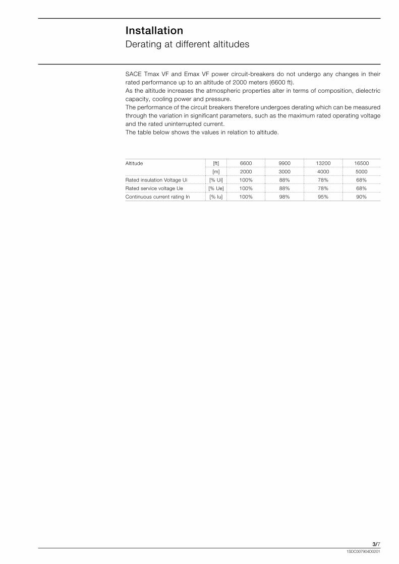
SACE.Tmax.VF.and.Emax.VF.power.circuit-breakers.do.not.undergo.any.changes. in. their.rated.performance.up.to.an.altitude.of.2000.meters.(6600.ft).As.the.altitude.increases.the.atmospheric.properties.alter.in.terms.of.composition,.dielectric.capacity,.cooling.power.and.pressure.The.performance.of.the.circuit.breakers.therefore.undergoes.derating.which.can.be.measured.through.the.variation.in.significant.parameters,.such.as.the.maximum.rated.operating.voltageand.the.rated.uninterrupted.current.The.table.below.shows.the.values.in.relation.to.altitude.
InstallationDerating.at.different.altitudes
Altitude. [ft] 6600 9900 13200 16500
[m] 2000 3000 4000 5000
Rated.insulation.Voltage.Ui [%.Ui] 100% 88% 78% 68%
Rated.service.voltage.Ue [%.Ue] 100% 88% 78% 68%
Continuous.current.rating.In [%.Iu] 100% 98% 95% 90%

4/11SDC007904D0201
Content
Thermal magnetic trip unit..................................................................................................... 4/2
PR222/VF................................................................................................................................ 4/4
PR111/VF................................................................................................................................ 4/7
PR122/VF................................................................................................................................4/10
Optional modules...................................................................................................................4/16
Protection trip units and trip curves
4/21SDC007904D0201
Protection trip units and trip curvesThermal.magnetic.trip.unit
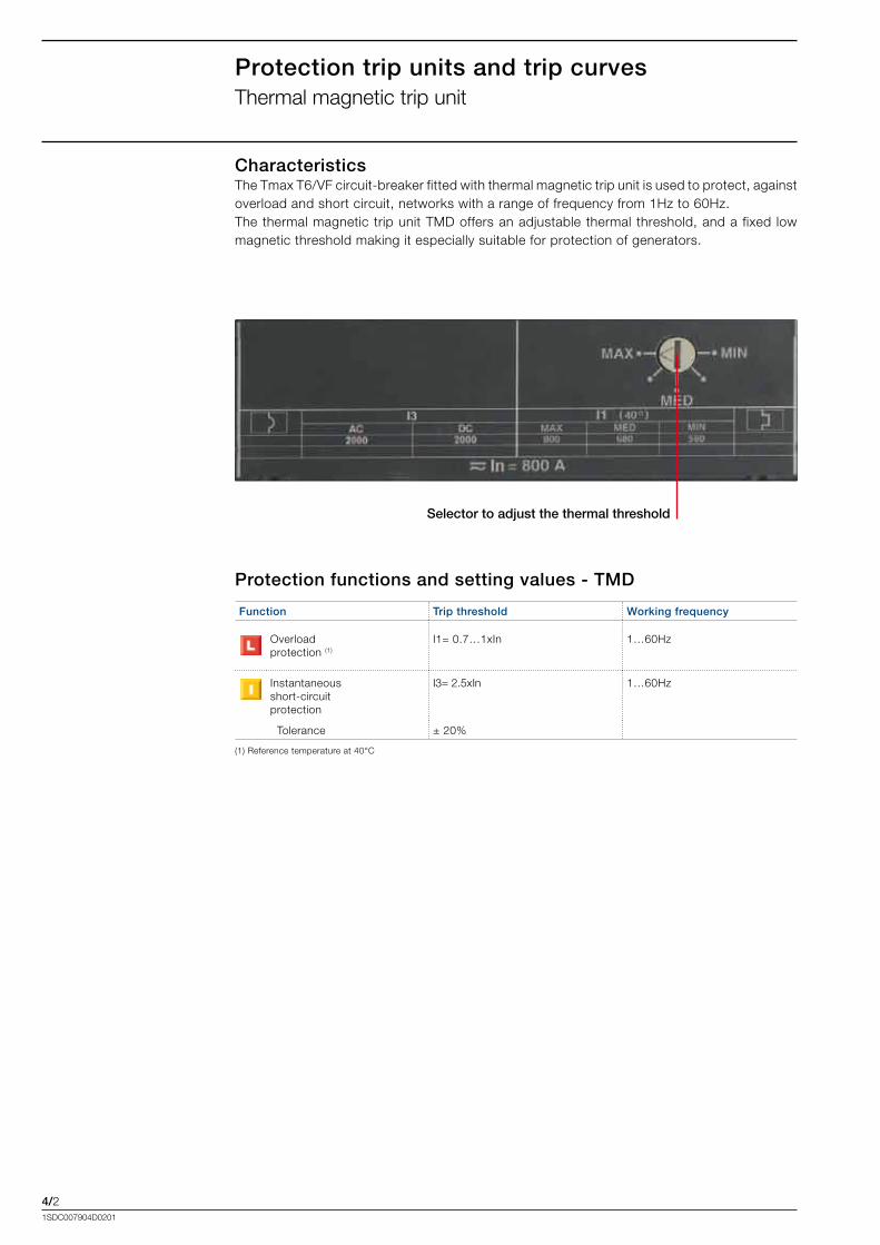
CharacteristicsThe.Tmax.T6/VF.circuit-breaker.fitted.with.thermal.magnetic.trip.unit.is.used.to.protect,.against.overload.and.short.circuit,.networks.with.a.range.of.frequency.from.1Hz.to.60Hz..The.thermal.magnetic.trip.unit.TMD.offers.an.adjustable.thermal. threshold,.and.a.fixed. low.magnetic.threshold.making.it.especially.suitable.for.protection.of.generators..
Function Trip threshold Working frequency
Overloadprotection.(1)
I1=.0.7…1xIn 1…60Hz
Instantaneousshort-circuitprotection
I3=.2.5xIn 1…60Hz
..Tolerance ±.20%
(1).Reference.temperature.at.40°C
Protection functions and setting values - TMD
Selector to adjust the thermal threshold
4/31SDC007904D0201
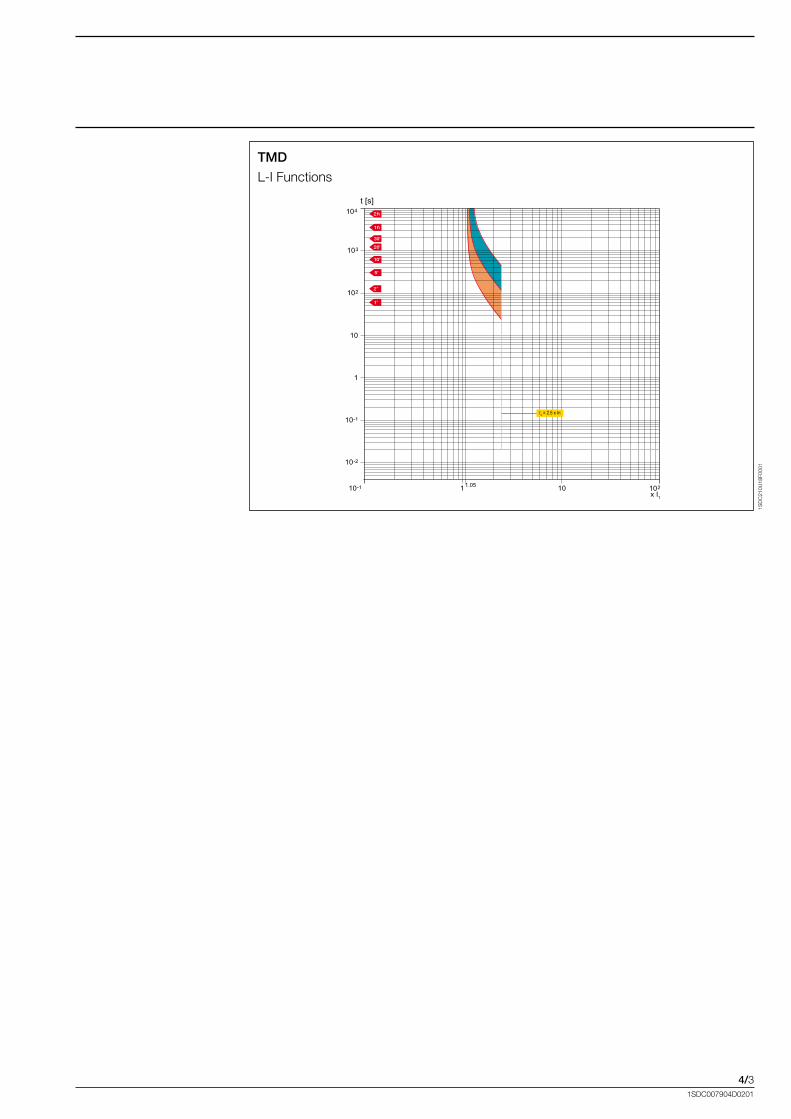
TMD
L-I.Functions
1SD
C21
0U18
F000
1
103
t [s]
x I1
10-1 101
10
1
102
10-1
10-2
1.05 102
104
I3 = 2.5 x In
4/41SDC007904D0201
Protection trip units and trip curvesPR222/VF
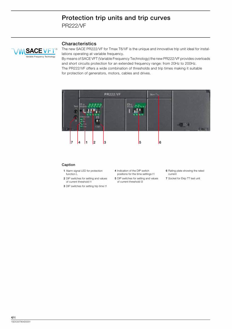
CharacteristicsThe.new.SACE.PR222/VF.for.Tmax.T6/VF.is.the.unique.and.innovative.trip.unit.ideal.for.instal-lations.operating.at.variable.frequency.By.means.of.SACE.VFT.(Variable.Frequency.Technology).the.new.PR222/VF.provides.overloads.and.short.circuits.protection.for.an.extended.frequency.range:.from.20Hz.to.200Hz.The.PR222/VF.offers.a.wide.combination.of.thresholds.and.trip.times.making.it.suitable.for.protection.of.generators,.motors,.cables.and.drives.
. 1..Alarm.signal.LED.for.protection.function.L
. 2..DIP.switches.for.setting.and.values.of.current.threshold.I1
. 3..DIP.switches.for.setting.trip.time.t1
Caption
. 4..Indication.of.the.DIP.switch.positions.for.the.time.settings.t1
. 5..DIP.switches.for.setting.and.values.of.current.threshold.I3
. 6.Rating.plate.showing.the.rated.current
. 7..Socket.for.Ekip.TT.test.unit
7 2 5 64 1 3
Pantone Process Cyan PCPantone solid to process 2975 PC
Black
Colors
RAL 7012
ABB SACE SpA
Curzio Cucinotta 10/11/2010
Titolo: Loghi SACE VFT e SACE LTT
-40°CLow Temperature TechnologySACE R
Variable Frequency Technology
SACE R
10,0
00 m
m
50,000 mm 50,000 mm
14,0
00 m
m
54,000 mm 54,000 mm
-40°CLow Temperature TechnologySACE R
Variable Frequency Technology
SACE R
4/51SDC007904D0201
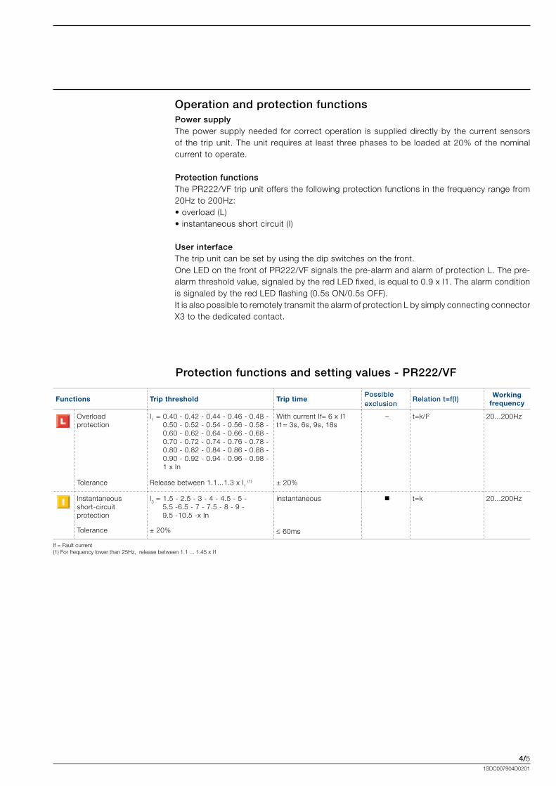
Operation and protection functionsPower supplyThe.power.supply.needed. for.correct.operation. is. supplied.directly.by. the.current. sensors.of. the.trip.unit..The.unit. requires.at. least. three.phases.to.be. loaded.at.20%.of. the.nominal.current.to.operate.
Protection functionsThe.PR222/VF.trip.unit.offers.the.following.protection.functions.in.the.frequency.range.from.20Hz.to.200Hz:•.overload.(L)•.instantaneous.short.circuit.(I)
User interfaceThe.trip.unit.can.be.set.by.using.the.dip.switches.on.the.front.One.LED.on.the.front.of.PR222/VF.signals.the.pre-alarm.and.alarm.of.protection.L..The.pre-alarm.threshold.value,.signaled.by.the.red.LED.fixed,.is.equal.to.0.9.x.I1..The.alarm.condition.is.signaled.by.the.red.LED.flashing.(0.5s.ON/0.5s.OFF).It.is.also.possible.to.remotely.transmit.the.alarm.of.protection.L.by.simply.connecting.connector.X3.to.the.dedicated.contact..
Functions Trip threshold Trip timePossibleexclusion
Relation t=f(I)Working
frequency
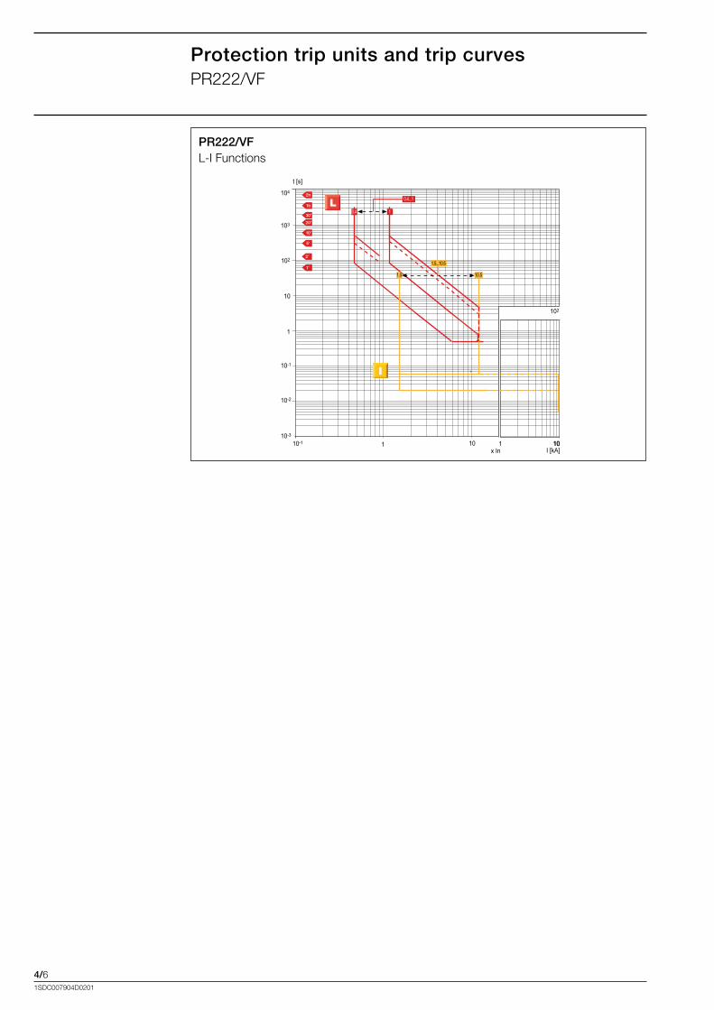
Overloadprotection
I1.=.0.40.-.0.42.-.0.44.-.0.46.-.0.48.-.. 0.50.-.0.52.-.0.54.-.0.56.-.0.58.-... 0.60.-.0.62.-.0.64.-.0.66.-.0.68.-... 0.70.-.0.72.-.0.74.-.0.76.-.0.78.-... 0.80.-.0.82.-.0.84.-.0.86.-.0.88.-.........
0.90.-.0.92.-.0.94.-.0.96.-.0.98.-.. 1.x.In
With.current.If=.6.x.I1t1=.3s,.6s,.9s,.18s
– t=k/I2 20...200Hz
Tolerance Release.between.1.1...1.3.x.I1.(1) ±.20%.
Instantaneousshort-circuitprotection
I3.=.1.5.-.2.5.-.3.-.4.-.4.5.-.5.-.........5.5.-6.5.-.7.-.7.5.-.8.-.9.-...........9.5.-10.5.-x.In
instantaneous. t=k 20...200Hz
Tolerance ±.20% ≤.60ms
If.=.Fault.current(1).For.frequency.lower.than.25Hz,..release.between.1.1.....1.45.x.I1
Protection functions and setting values - PR222/VF
4/61SDC007904D0201
Protection trip units and trip curvesPR222/VF
PR222/VFL-I.Functions
t [s]
1I [kA]
10
10-1
10-2
1
10
102
103
104
10-110-3
10x In
102
1 10
0.4 1
1.5 10.5
0.4...1
1.5...10.5
4/71SDC007904D0201
Protection trip units and trip curvesPR111/VF
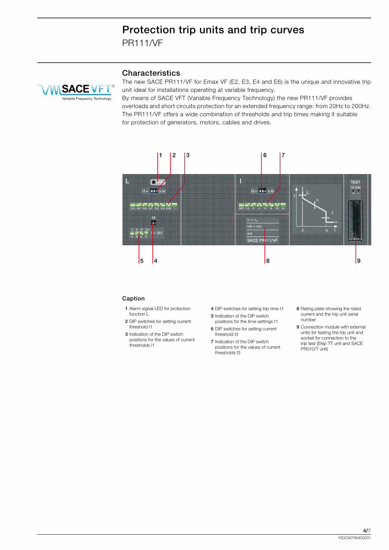
CharacteristicsThe.new.SACE.PR111/VF.for.Emax.VF.(E2,.E3,.E4.and.E6).is.the.unique.and.innovative.trip.unit.ideal.for.installations.operating.at.variable.frequency.By.means.of.SACE.VFT.(Variable.Frequency.Technology).the.new.PR111/VF.provides.overloads.and.short.circuits.protection.for.an.extended.frequency.range:.from.20Hz.to.200Hz.The.PR111/VF.offers.a.wide.combination.of.thresholds.and.trip.times.making.it.suitable.for.protection.of.generators,.motors,.cables.and.drives.
. 1..Alarm.signal.LED.for.protection.function.L
. 2..DIP.switches.for.setting.current.threshold.I1
. 3..Indication.of.the.DIP.switch.positions.for.the.values.of.current.thresholds.I1
Caption
. 4..DIP.switches.for.setting.trip.time.t1.
. 5..Indication.of.the.DIP.switch.positions.for.the.time.settings.t1
. 6.DIP.switches.for.setting.current.threshold.I3
. 7..Indication.of.the.DIP.switch.positions.for.the.values.of.current.thresholds.I3
. 8..Rating.plate.showing.the.rated.current.and.the.trip.unit.serial.number
. 9..Connection.module.with.external.units.for.testing.the.trip.unit.and.socket.for.connection.to.the.trip.test.(Ekip.TT.unit.and.SACE.PR010/T.unit)
2
5
1 3 6 7
4 98
Pantone Process Cyan PCPantone solid to process 2975 PC
Black
Colors
RAL 7012
ABB SACE SpA
Curzio Cucinotta 10/11/2010
Titolo: Loghi SACE VFT e SACE LTT
-40°CLow Temperature TechnologySACE R
Variable Frequency Technology
SACE R
10,0
00 m
m
50,000 mm 50,000 mm
14,0
00 m
m
54,000 mm 54,000 mm
-40°CLow Temperature TechnologySACE R
Variable Frequency Technology
SACE R
4/81SDC007904D0201
Protection trip units and trip curvesPR111/VF
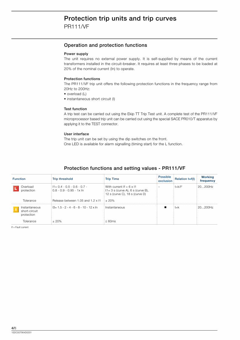
Operation and protection functions
Power supplyThe. unit. requires. no. external. power. supply.. It. is. self-supplied. by. means. of. the. current.transformers.installed.in.the.circuit-breaker..It.requires.at.least.three.phases.to.be.loaded.at.20%.of.the.nominal.current.(In).to.operate.
Protection functionsThe.PR111/VF.trip.unit.offers.the.following.protection.functions.in.the.frequency.range.from.20Hz.to.200Hz:•.overload.(L)•.instantaneous.short.circuit.(I)
Test functionA.trip.test.can.be.carried.out.using.the.Ekip.TT.Trip.Test.unit..A.complete.test.of.the.PR111/VF.microprocessor.based.trip.unit.can.be.carried.out.using.the.special.SACE.PR010/T.apparatus.by.applying.it.to.the.TEST.connector.
User interfaceThe.trip.unit.can.be.set.by.using.the.dip.switches.on.the.front.One.LED.is.available.for.alarm.signalling.(timing.start).for.the.L.function.
Protection functions and setting values - PR111/VF
Function Trip threshold Trip TimePossibleexclusion
Relation t=f(I)Working
frequency
Overloadprotection
I1=.0.4.-.0.5.-.0.6.-.0.7.-.0.8.-.0.9.-.0.95.-.1x.In
With.current.If.=.6.x.I1t1=.3.s.(curve.A),.6.s.(curve.B),12.s.(curve.C),.18.s.(curve.D)
– t=k/I2 20...200Hz
..Tolerance. Release.between.1.05.and.1.2.x.I1 ±.20%
Instantaneousshort-circuitprotection
I3=.1.5.-.2.-.4.-.6.-.8.-.10.-.12.x.In Instantaneous t=k 20...200Hz
..Tolerance. ±.20% ≤.60ms
If.=.Fault.current
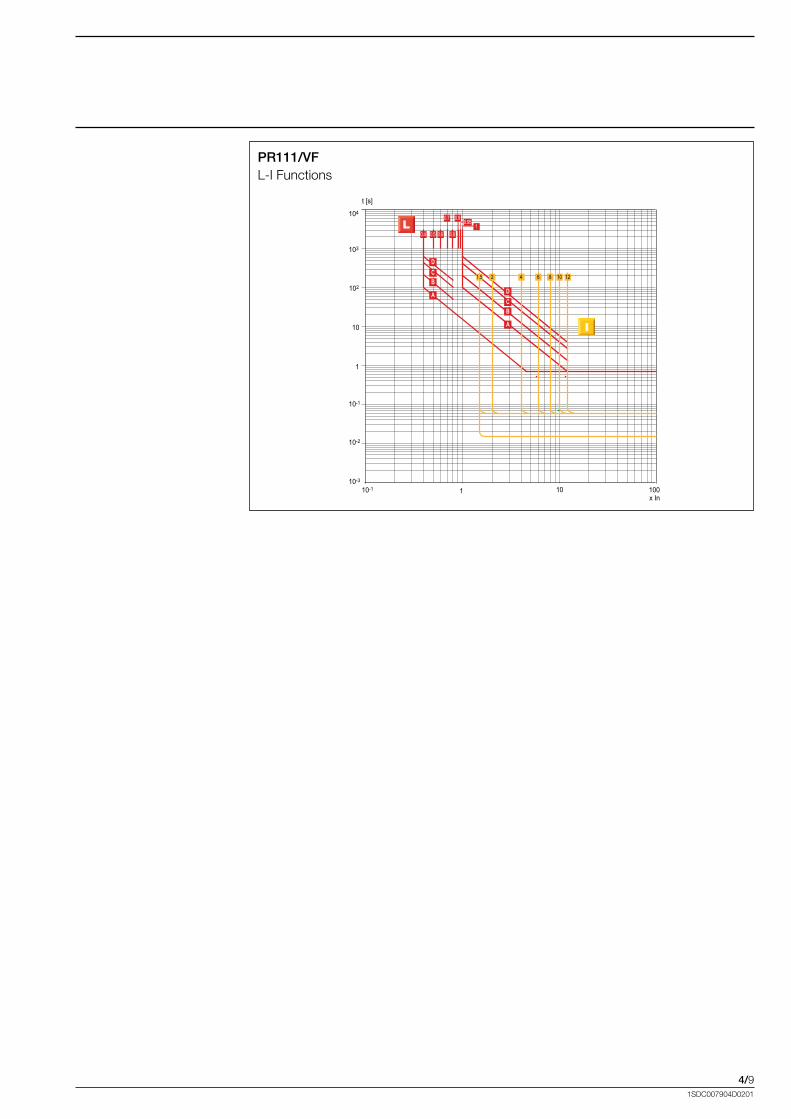
4/91SDC007904D0201
PR111/VFL-I.Functions
t [s]
1 10
10-1
10-2
1
10
102
103
104
10-110-3
100
0.4 0.5 0.6 0.8
0.71
x In
2 4 6 81.5 10 12
0.90.95
A
BCD
A
BCD
4/101SDC007904D0201
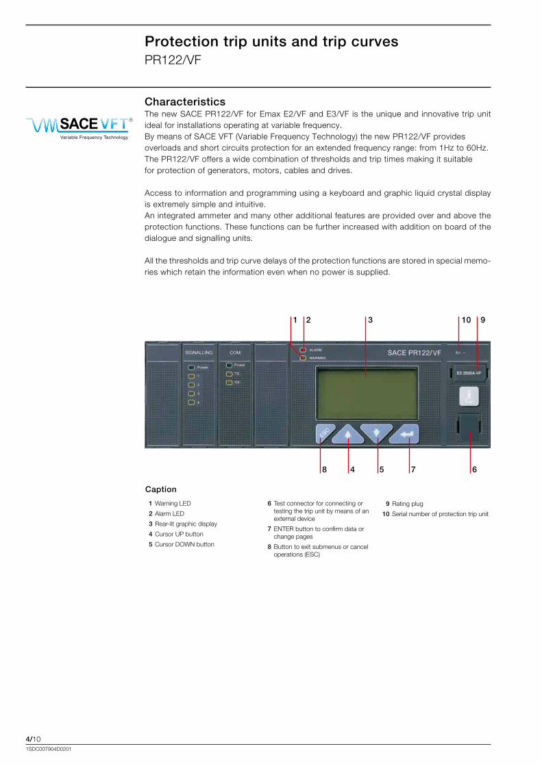
Protection trip units and trip curvesPR122/VF
CharacteristicsThe.new.SACE.PR122/VF.for.Emax.E2/VF.and.E3/VF. is. the.unique.and. innovative.trip.unit.ideal.for.installations.operating.at.variable.frequency.By.means.of.SACE.VFT.(Variable.Frequency.Technology).the.new.PR122/VF.provides.overloads.and.short.circuits.protection.for.an.extended.frequency.range:.from.1Hz.to.60Hz.The.PR122/VF.offers.a.wide.combination.of.thresholds.and.trip.times.making.it.suitable.for.protection.of.generators,.motors,.cables.and.drives.
Access.to.information.and.programming.using.a.keyboard.and.graphic.liquid.crystal.display.is.extremely.simple.and.intuitive..An.integrated.ammeter.and.many.other.additional.features.are.provided.over.and.above.the.protection.functions..These.functions.can.be.further.increased.with.addition.on.board.of.the.dialogue.and.signalling.units..
All.the.thresholds.and.trip.curve.delays.of.the.protection.functions.are.stored.in.special.memo-ries.which.retain.the.information.even.when.no.power.is.supplied.
10
8
2 31 9
4 5 7 6
1.Warning.LED..
. 2.Alarm.LED.
. 3.Rear-lit.graphic.display
. 4.Cursor.UP.button
. 5.Cursor.DOWN.button
6. Test.connector.for.connecting.or.testing.the.trip.unit.by.means.of.an.external.device
. 7.ENTER.button.to.confirm.data.or.change.pages
. 8.Button.to.exit.submenus.or.cancel.operations.(ESC)
Caption
9 Rating.plug
10.Serial.number.of.protection.trip.unit
Pantone Process Cyan PCPantone solid to process 2975 PC
Black
Colors
RAL 7012
ABB SACE SpA
Curzio Cucinotta 10/11/2010
Titolo: Loghi SACE VFT e SACE LTT
-40°CLow Temperature TechnologySACE R
Variable Frequency Technology
SACE R
10,0
00 m
m
50,000 mm 50,000 mm
14,0
00 m
m
54,000 mm 54,000 mm
-40°CLow Temperature TechnologySACE R
Variable Frequency Technology
SACE R
4/111SDC007904D0201
Operation, protection functions and self-test
Protection functions The.PR122/VF.trip.unit.offers.the.following.protection.functions.in.the.frequency.range.from.1.to.60Hz:..•. overload.(L).•. instantaneous.short-circuit.(I).•. self-protection.against.overtemperature.(OT)
Setting the frequencyThe.PR122/VF.is.a.new.relay.designed.to.work.in.a.wide.range.of.frequency..The.working.frequency.can.be.set.by.selecting.the.nominal.frequency.(from.6.6Hz.to.50Hz)..Once.the.nominal.frequency.has.been.set,.the.trip.unit.works.in.a.frequency.range.from.0.2.x.fn.to.1.25.x.fn..The.following.table.shows.the.possible.nominal.frequency.values.and.the.corresponding.working.range.
Nominal Frequency (fn) Working range
6.6.Hz............... 1...8Hz
16.6.Hz............. 3...20Hz
25.Hz.................. 5...30Hz
50.Hz.................. 10...60Hz
Start-up functionThe.start-up.function.allows.protection.to.operate.with.higher.trip.thresholds.during.the.start-up.phase..This.avoids.untimely.tripping.caused.by.the.high. inrush.currents.of.certain. loads.like.motors..The.start-up.phase.lasts.from.100.ms.to.1.5.s,.in.steps.of.0.05.s..It.is.automatically.recognized.by.the.PR122/VF.when.the.peak.value.of.the.maximum.current.exceeds.0.1.x.In.
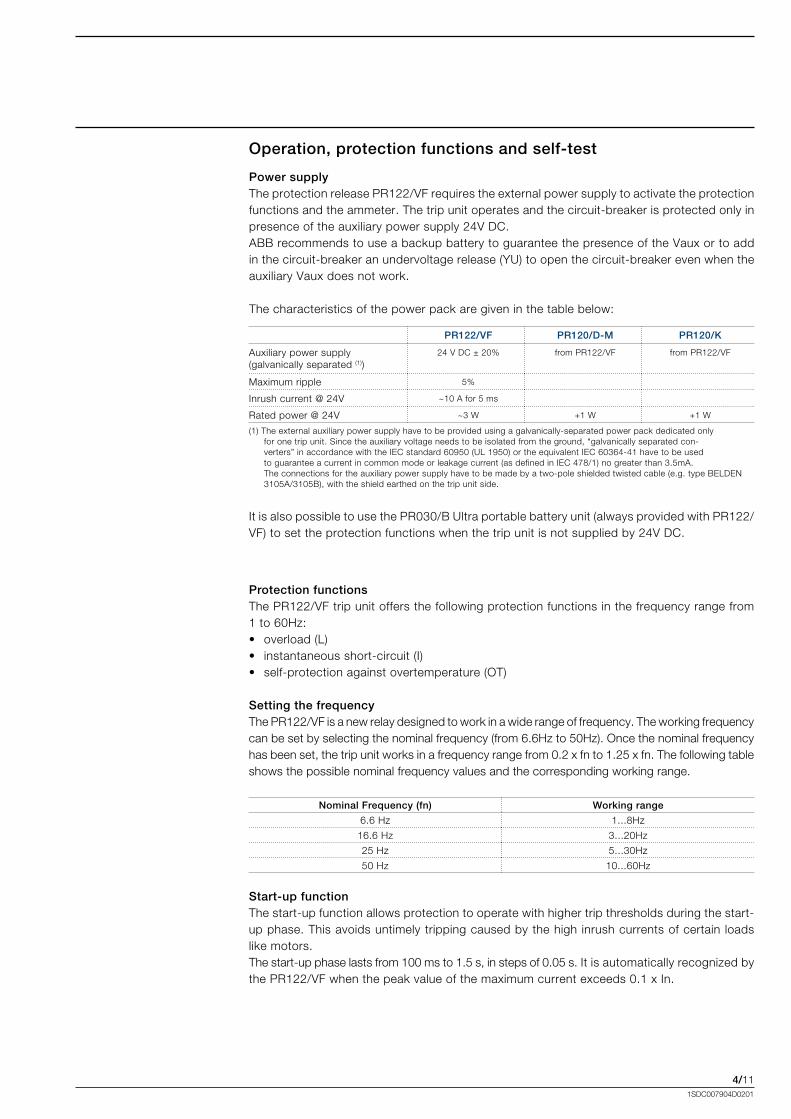
Power supplyThe.protection.release.PR122/VF.requires.the.external.power.supply.to.activate.the.protection.functions.and.the.ammeter..The.trip.unit.operates.and.the.circuit-breaker.is.protected.only.in.presence.of.the.auxiliary.power.supply.24V.DC.ABB.recommends.to.use.a.backup.battery.to.guarantee.the.presence.of.the.Vaux.or.to.add.in.the.circuit-breaker.an.undervoltage.release.(YU).to.open.the.circuit-breaker.even.when.the.auxiliary.Vaux.does.not.work.
The.characteristics.of.the.power.pack.are.given.in.the.table.below:
PR122/VF PR120/D-M PR120/K
Auxiliary.power.supply.(galvanically.separated.(1))
24.V.DC.±.20% from.PR122/VF from.PR122/VF
Maximum.ripple. 5%
[email protected] ~10.A.for.5.ms
[email protected] ~3.W +1.W +1.W
(1).The.external.auxiliary.power.supply.have.to.be.provided.using.a.galvanically-separated.power.pack.dedicated.only.for.one.trip.unit..Since.the.auxiliary.voltage.needs.to.be.isolated.from.the.ground,.“galvanically.separated.con-verters”.in.accordance.with.the.IEC.standard.60950.(UL.1950).or.the.equivalent.IEC.60364-41.have.to.be.used.to.guarantee.a.current.in.common.mode.or.leakage.current.(as.defined.in.IEC.478/1).no.greater.than.3.5mA........................................................................The.connections.for.the.auxiliary.power.supply.have.to.be.made.by.a.two-pole.shielded.twisted.cable.(e.g..type.BELDEN.3105A/3105B),.with.the.shield.earthed.on.the.trip.unit.side.
It.is.also.possible.to.use.the.PR030/B.Ultra.portable.battery.unit.(always.provided.with.PR122/VF).to.set.the.protection.functions.when.the.trip.unit.is.not.supplied.by.24V.DC.
4/121SDC007904D0201
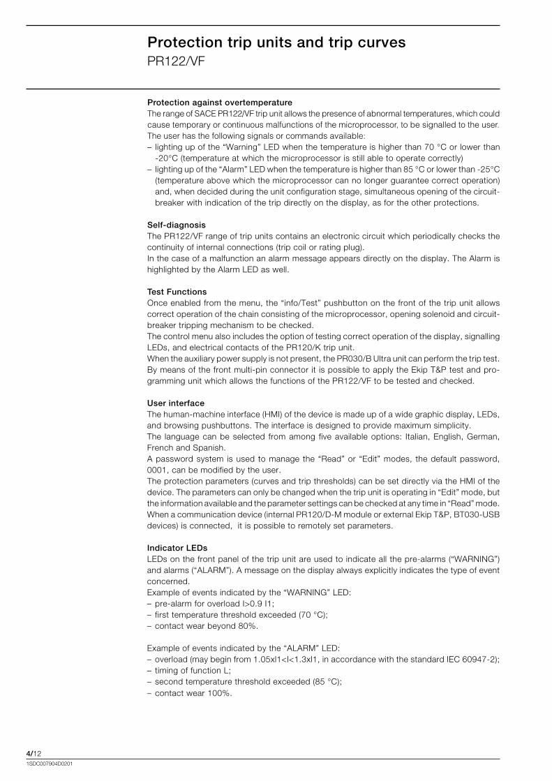
Protection against overtemperatureThe range of SACE PR122/VF trip unit allows the presence of abnormal temperatures, which could cause temporary or continuous malfunctions of the microprocessor, to be signalled to the user.The user has the following signals or commands available:–..lighting.up.of.the.“Warning”.LED.when.the.temperature.is.higher.than.70.°C.or.lower.than.
-20°C.(temperature.at.which.the.microprocessor.is.still.able.to.operate.correctly)–..lighting.up.of.the.“Alarm”.LED.when.the.temperature.is.higher.than.85.°C.or.lower.than.-25°C.
(temperature.above.which.the.microprocessor.can.no.longer.guarantee.correct.operation).and,.when.decided.during.the.unit.configuration.stage,.simultaneous.opening.of.the.circuit-breaker.with.indication.of.the.trip.directly.on.the.display,.as.for.the.other.protections.
Self-diagnosisThe.PR122/VF.range.of.trip.units.contains.an.electronic.circuit.which.periodically.checks.the.continuity.of.internal.connections.(trip.coil.or.rating.plug).In.the.case.of.a.malfunction.an.alarm.message.appears.directly.on.the.display..The.Alarm.is.highlighted.by.the.Alarm.LED.as.well.
Test FunctionsOnce.enabled.from.the.menu,.the.“info/Test”.pushbutton.on.the.front.of.the.trip.unit.allows.correct.operation.of.the.chain.consisting.of.the.microprocessor,.opening.solenoid.and.circuit-breaker.tripping.mechanism.to.be.checked.The.control.menu.also.includes.the.option.of.testing.correct.operation.of.the.display,.signalling.LEDs,.and.electrical.contacts.of.the.PR120/K.trip.unit.When.the.auxiliary.power.supply.is.not.present,.the.PR030/B.Ultra.unit.can.perform.the.trip.test.By.means.of.the.front.multi-pin.connector.it.is.possible.to.apply.the.Ekip.T&P.test.and.pro-gramming.unit.which.allows.the.functions.of.the.PR122/VF.to.be.tested.and.checked..
User interfaceThe.human-machine.interface.(HMI).of.the.device.is.made.up.of.a.wide.graphic.display,.LEDs,.and.browsing.pushbuttons..The.interface.is.designed.to.provide.maximum.simplicity...The. language.can.be.selected. from.among. five.available.options:. Italian,.English,.German,.French.and.Spanish.A.password.system. is.used. to.manage. the.“Read”.or. “Edit”.modes,. the.default.password,.0001,.can.be.modified.by.the.user.The.protection.parameters.(curves.and.trip.thresholds).can.be.set.directly.via.the.HMI.of.the.device..The.parameters.can.only.be.changed.when.the.trip.unit.is.operating.in.“Edit”.mode,.but.the.information.available.and.the.parameter.settings.can.be.checked.at.any.time.in.“Read”.mode.When.a.communication.device.(internal.PR120/D-M.module.or.external.Ekip.T&P,.BT030-USB.devices).is.connected,..it.is.possible.to.remotely.set.parameters..
Indicator LEDs LEDs.on.the.front.panel.of.the.trip.unit.are.used.to.indicate.all.the.pre-alarms.(“WARNING”).and.alarms.(“ALARM”)..A.message.on.the.display.always.explicitly.indicates.the.type.of.event.concerned..Example.of.events.indicated.by.the.“WARNING”.LED:–..pre-alarm.for.overload.I>0.9.I1;–..first.temperature.threshold.exceeded.(70.°C);–..contact.wear.beyond.80%.
Example.of.events.indicated.by.the.“ALARM”.LED:–..overload.(may.begin.from.1.05xl1<I<1.3xl1,.in.accordance.with.the.standard.IEC.60947-2);.–..timing.of.function.L;–..second.temperature.threshold.exceeded.(85.°C);–..contact.wear.100%.
Protection trip units and trip curvesPR122/VF
4/131SDC007904D0201
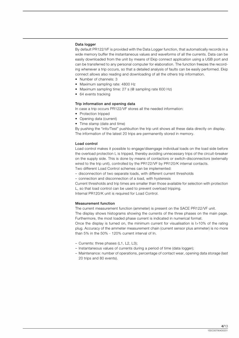
Data loggerBy.default.PR122/VF.is.provided.with.the.Data.Logger.function,.that.automatically.records.in.a.wide.memory.buffer.the.instantaneous.values.and.waveforms.of.all.the.currents..Data.can.be.easily.downloaded.from.the.unit.by.means.of.Ekip.connect.application.using.a.USB.port.and.can.be.transferred.to.any.personal.computer.for.elaboration..The.function.freezes.the.record-ing.whenever.a.trip.occurs,.so.that.a.detailed.analysis.of.faults.can.be.easily.performed..Ekip.connect.allows.also.reading.and.downloading.of.all.the.others.trip.information.•. Number.of.channels:.3•. Maximum.sampling.rate:.4800.Hz•. Maximum.sampling.time:.27.s.(@.sampling.rate.600.Hz)•. 64.events.tracking
Trip information and opening dataIn.case.a.trip.occurs.PR122/VF.stores.all.the.needed.information:•. Protection.tripped•. Opening.data.(current)•. Time.stamp.(date.and.time)By.pushing.the.“info/Test”.pushbutton.the.trip.unit.shows.all.these.data.directly.on.display..The.information.of.the.latest.20.trips.are.permanently.stored.in.memory.
Load controlLoad.control.makes.it.possible.to.engage/disengage.individual.loads.on.the.load.side.before.the.overload.protection.L.is.tripped,.thereby.avoiding.unnecessary.trips.of.the.circuit-breaker.on.the.supply.side..This.is.done.by.means.of.contactors.or.switch-disconnectors.(externally.wired.to.the.trip.unit),.controlled.by.the.PR122/VF.by.PR120/K.internal.contacts.Two.different.Load.Control.schemes.can.be.implemented:–.disconnection.of.two.separate.loads,.with.different.current.thresholds–. connection.and.disconnection.of.a.load,.with.hysteresisCurrent.thresholds.and.trip.times.are.smaller.than.those.available.for.selection.with.protection.L,.so.that.load.control.can.be.used.to.prevent.overload.tripping.Internal.PR120/K.unit.is.required.for.Load.Control.
Measurement functionThe.current.measurement.function.(ammeter).is.present.on.the.SACE.PR122/VF.unit.The.display.shows.histograms.showing.the.currents.of.the.three.phases.on.the.main.page..Furthermore,.the.most.loaded.phase.current.is.indicated.in.numerical.format..Once. the.display. is. turned.on,. the.minimum.current. for.visualisation. is. I>10%.of. the. rating.plug..Accuracy.of.the.ammeter.measurement.chain.(current.sensor.plus.ammeter).is.no.more.than.5%.in.the.50%.-.120%.current.interval.of.In..
–.Currents:.three.phases.(L1,.L2,.L3);–. Instantaneous.values.of.currents.during.a.period.of.time.(data.logger);–..Maintenance:.number.of.operations,.percentage.of.contact.wear,.opening.data.storage.(last.
20.trips.and.80.events).
4/141SDC007904D0201
OT
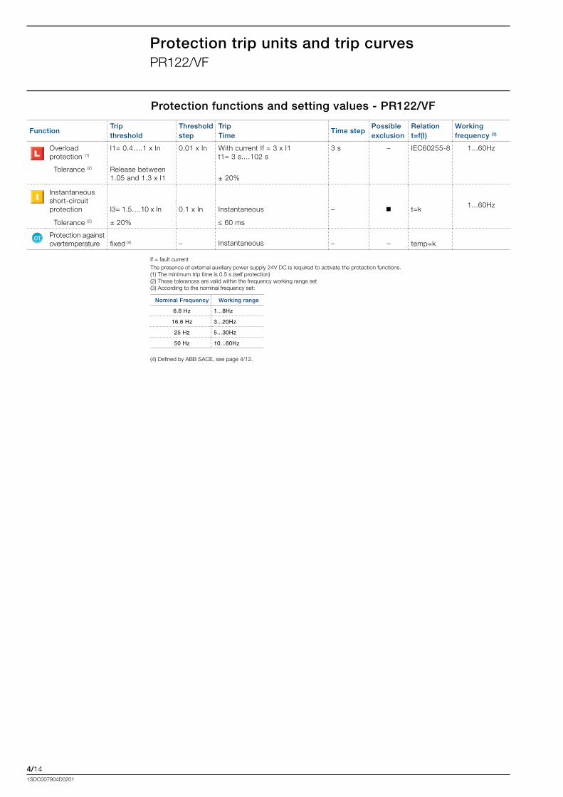
If.=.fault.currentThe.presence.of.external.auxiliary.power.supply.24V.DC.is.required.to.activate.the.protection.functions..(1).The.minimum.trip.time.is.0.5.s.(self.protection)(2).These.tolerances.are.valid.within.the.frequency.working.range.set(3).According.to.the.nominal.frequency.set:
Protection functions and setting values - PR122/VF
Nominal Frequency Working range
6.6 Hz 1...8Hz
16.6 Hz 3...20Hz
25 Hz 5...30Hz
50 Hz 10...60Hz
FunctionTripthreshold
Thresholdstep
TripTime
Time stepPossibleexclusion
Relationt=f(I)
Workingfrequency (3)
Overloadprotection.(1)
I1=.0.4….1.x.In 0.01.x.In With.current.If.=.3.x.I1t1=.3.s....102.s
3.s – IEC60255-8 1...60Hz
..Tolerance.(2) Release.between1.05.and.1.3.x.I1 ±.20%
Instantaneousshort-circuitprotection I3=.1.5….10.x.In 0.1.x.In Instantaneous – t=k
1...60Hz
..Tolerance.(2) ±.20% ≤.60.ms
Protection.againstovertemperature fixed.(4) – Instantaneous – – temp=k .
Protection trip units and trip curvesPR122/VF
(4).Defined.by.ABB.SACE,.see.page.4/12.
4/151SDC007904D0201
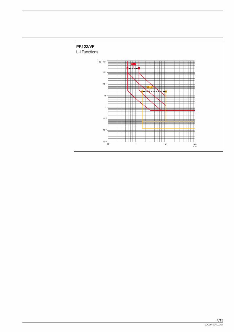
PR122/VFL-I.Functions
4/161SDC007904D0201
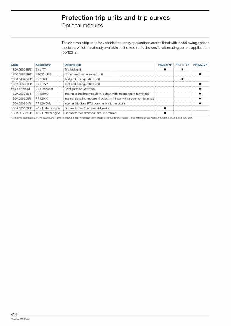
Protection trip units and trip curvesOptional.modules
Code Accessory Description PR222/VF PR111/VF PR122/VF
1SDA066988R1 Ekip.TT Trip.test.unit
1SDA058259R1 BT030-USB Communication.wireless.unit
1SDA048964R1 PR010/T Test.and.configuration.unit
1SDA066989R1 Ekip.T&P Test.and.configuration.unit
free.download Ekip.connect Configuration.software
1SDA058255R1 PR120/K Internal.signalling.module.(4.output.with.independent.terminals)
1SDA058256R1 PR120/K Internal.signalling.module.(4.output.+.1.input.with.a.common.terminal)
1SDA058254R1 PR120/D-M Internal.Modbus.RTU.communication.module.
1SDA055059R1 X3.-.L.alarm.signal. Connector.for.fixed.circuit-breaker
1SDA055061R1 X3.-.L.alarm.signal. Connector.for.draw.out.circuit-breaker
For.further.information.on.the.accessories,.please.consult.Emax.catalogue.low.voltage.air.circuit-breakers.and.Tmax.catalogue.low.voltage.moulded-case.circuit-breakers.
The.electronic.trip.units.for.variable.frequency.applications.can.be.fitted.with.the.following.optional.modules,.which.are.already.available.on.the.electronic.devices.for.alternating.current.applications.(50/60Hz).
5/11SDC007904D0201
Content
Electrical and mechanical accessories: Tmax................................................................. 5/2
Connection terminals: Tmax............................................................................................... 5/3
Electrical and mechanical accessories: Emax................................................................. 5/4
Accessories
5/21SDC007904D0201
AccessoriesElectrical.and.mechanical.accessories:.Tmax
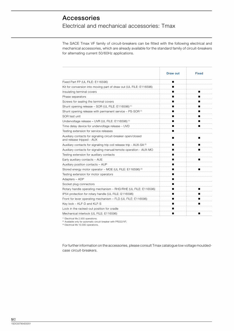
The.SACE.Tmax.VF.family.of.circuit-breakers.can.be.fitted.with.the. following.electrical.and.mechanical.accessories,.which.are.already.available.for.the.standard.family.of.circuit-breakers.for.alternating.current.50/60Hz.applications.
Draw out Fixed
Fixed.Part.FP.(UL.FILE:.E116596)
Kit.for.conversion.into.moving.part.of.draw.out.(UL.FILE:.E116596)
Insulating.terminal.covers
Phase.separators
Screws.for.sealing.the.terminal.covers
Shunt.opening.release.–.SOR.(UL.FILE:.E116596).(1)
Shunt.opening.release.with.permanent.service.–.PS-SOR.(1)
SOR.test.unit..
Undervoltage.release.–.UVR.(UL.FILE:.E116596).(1)
Time.delay.device.for.undervoltage.release.–.UVD
Testing.extension.for.service.releases
Auxiliary.contacts.for.signaling.circuit-breaker.open/closed.and.release.tripped.-.AUX
Auxiliary.contacts.for.signaling.trip.coil.release.trip.-.AUX-SA.(2)
Auxiliary.contacts.for.signaling.manual/remote.operation.-.AUX-MO
Testing.extension.for.auxiliary.contacts
Early.auxiliary.contacts.–.AUE
Auxiliary.position.contacts.–.AUP
Stored.energy.motor.operator.–.MOE.(UL.FILE:.E116596).(3)
Testing.extension.for.motor.operators
Adapters.–.ADP
Socket.plug.connectors
Rotary.handle.operating.mechanism.–.RHD/RHE.(UL.FILE:.E116596)
IP54.protection.for.rotary.handle.(UL.FILE:.E116596)
Front.for.lever.operating.mechanism.–.FLD.(UL.FILE:.E116596)
Key.lock.–.KLF-D.and.KLF-S
Lock.in.the.racked-out.position.for.cradle
Mechanical.interlock.(UL.FILE:.E116596) (1).Electrical.life.2.500.operations;.(2).Available.only.for.automatic.circuit-breaker.with.PR222/VF;(3).Electrical.life.10.000.operations.
For.further.information.on.the.accessories,.please.consult.Tmax.catalogue.low.voltage.moulded-case.circuit-breakers.

5/31SDC007904D0201
AccessoriesConnection.terminals:.Tmax
Circuit-breaker Fixed part
Fornt.terminals.for.CuAl.cables.-.FcCuAl.3*185.(1)
Rear.terminals.vertical.-.VR
Rear.terminals.horizontal.-.HR
Front.terminals.-.F
Rear.flat.vertical.terminals.-.VR.(1)
Rear.flat.horizontal.terminals.-.HR.(1)
Front.extended..terminals.-.EF.(1).................................................................................................... (1).UL.listed
The.SACE.Tmax.VF.family.of.circuit-breakers.can.be.fitted.with.the.following.terminals,.which.are.already.available.for.the.standard.family.of.circuit-breakers.for.alternating.current.50/60Hz.applications.
For.further.information.on.the.accessories,.please.consult.Tmax.catalogue.low.voltage.moulded-case.circuit-breakers.

5/41SDC007904D0201
AccessoriesElectrical.and.mechanical.accessories:.Emax
Draw out Fixed
1a).Shunt.opening/closing.release.(YO/YC).and.......second.shunt.opening.release.(YO2)
1b).SOR.test.unit..
2a).Undervoltage.release.(YU).(4)
2b).Time-delay.device.for.undervoltage.release.(D).
3)...Gearmotor.for.the.automatic.charging.of.the.closing.springs.(M)
4a).Electrical.signalling.of.electronic.release.tripped.(3)
4b).Electrical.signalling.of.electronic.release.tripped.with.remote.reset.command.(6)
5a).Electrical.signaling.of.circuit-breaker.open/closed.(1).(5)
5b).External.supplementary.electrical.signaling.of.circuit-breaker.open/closed
5c).Electrical.signaling.of.circuit-breaker.racked-in/test.isolated/racked-out
5d).Contact.signaling.closing.springs.charged
5e).Contact.signaling.undervoltage.release.de-energized.(C..Aux.YU)
7)...Mechanical.operation.counter
8a).Lock.in.open.position:.key
8b).Lock.in.open.position:.padlocks
8c).Circuit-breaker.lock.in.racked-in/test.isolated/racked-out.position
8d).Accessories.for.lock.in.test.isolated/racked-out.position
8e).Padlock.device.for.safety.shutter
8f)..Mechanical.lock.for.compartment.door
8g).Anti-racking-out.device.when.the.springs.are.charged.(FAIL.SAFE).(2)
9a).Protection.for.opening.and.closing.pushbuttons
9b).IP54.door.protection
10).Mechanical.interlock
11).Lift.device..................
(1).Four.auxiliary.contacts.are.included.as.standard.in.the.automatic.circuit-breaker;(2).Supplied.as.standard.in.withdrawable.versions.of.High.frequency/UL.and.Switch.disconnector/UL;.in.alternative.with.YU...................Incompatible.with.Low.frequency.versions;(3).Available.only.for.automatic.circuit-breaker;(4).In.alternative.with.anti-racking-out.device;(5).10.open/closed.contacts.are.in.alternative.with.PR120/K.
For. further. information.on. the. accessories,. please. consult. Emax. catalogue. low. voltage. air.circuit-breakers.
The.SACE.Emax.VF.family.of.circuit-breakers.can.be.fitted.with.the.following.electrical.and.mechanical.accessories,.which.are.already.available.for.the.standard.family.of.circuit-breakers.for.alternating.current.50/60Hz.applications.
6/11SDC007904D0201
Content
Tmax T6................................................................................................................................. 6/2
Accessories for Tmax T6..................................................................................................... 6/8
Distances to be respected for Tmax T6............................................................................6/13
Emax for low frequency applications................................................................................6/14
Emax for high frequency applications and switch disconnector..................................6/20
Accessories for Emax..........................................................................................................6/33
Installation in switchboard for Emax.................................................................................6/36
Overall dimensions
6/21SDC007904D0201
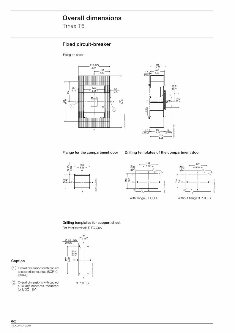
Overall dimensionsTmax.T6
Fixed circuit-breaker
1SD
C21
020A
F000
1
1SD
C21
021A
F000
1
152= =
77.7
5
138
3.06 5.98
5.43
149= =
66.7
5
116
5.87
2.63
4.57
1SD
C21
022A
F000
1
142= =
62.2
5
107
5.59
2.45
4.21
1SD
C21
023A
F000
1
1SD
C21
024A
F000
1
237
5.5 - M5
118.
5
702.76
Ø 0.22
4.67
9.33
1SD
C21
025A
F000
1
Fixing.on.sheet
Caption
..1. Overall.dimensions.with.cabled.accessories.mounted.(SOR-C,.UVR-C)
..2. Overall.dimensions.with.cabled.auxiliary. contacts. mounted.(only.3Q.1SY)
Drilling templates of the compartment door
With.flange.3.POLES Without.flange.3.POLES
Flange for the compartment door
Drilling templates for support sheetFor.front.terminals.F,.FC.CuAl
3.POLES
105
210 (3P)
5.52.7
134
268
140= =
4.13
8.27
0.11 0.225.51
10.5
5
361
14.2
1
105
61.25
1074.21
3
1596.26
103.54.07
1154.53
20.12 0.08
4.13
2.41
1.50.06
6/31SDC007904D0201
705.5 - M5
118.
5
150.
5
237
301
171.521.5R
2.76Ø 0.22
6.75R 0.85
9.33
11.8
5 4.66 5.
921S
DC
2102
7AF0
001
70
35Ø 5.5 M5
Ø 35
70 70
120.
5
241
237
118.
5
8
X X
Y
Y
2.76
1.38Ø 0.22
2.762.76
9.49
4.74
4.66
9.33
0.31
Ø 1.38
1SD
C21
029A
F000
1
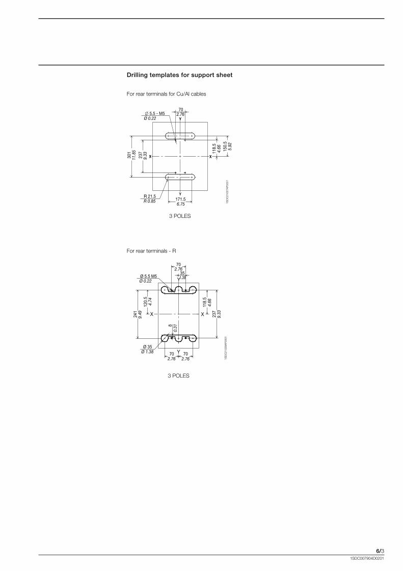
Drilling templates for support sheet
For.rear.terminals.for.Cu/Al.cables
3.POLES
For.rear.terminals.-.R
3.POLES
6/41SDC007904D0201
Overall dimensionsTmax.T6
MA
X 1
2
40MAX
18 M
IN
22.5 ±0.16.5
Ø 0.260.89
120.
5
23 MIN5 MAX100.9
4.74
1SD
C21
031A
F000
1
1SD
C21
032A
F000
1
19
120.
5
25.559
4.74
2.321
Ø 0.75
1SD
C21
033A
F000
1
1SD
C21
034A
F000
1
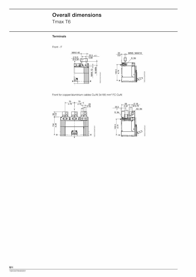
Terminals
Front.-.F
Front.for.copper/aluminium.cables.Cu/Al.3x185.mm2.FC.CuAl.
207070
134
39
2.76 2.760.79
1.53
5.28
6/51SDC007904D0201
1SD
C21
042A
F000
1
1SD
C21
043A
F000
1
1SD
C21
046A
F000
1
1SD
C21
045A
F000
1
1SD
C21
044A
F000
1
..1.
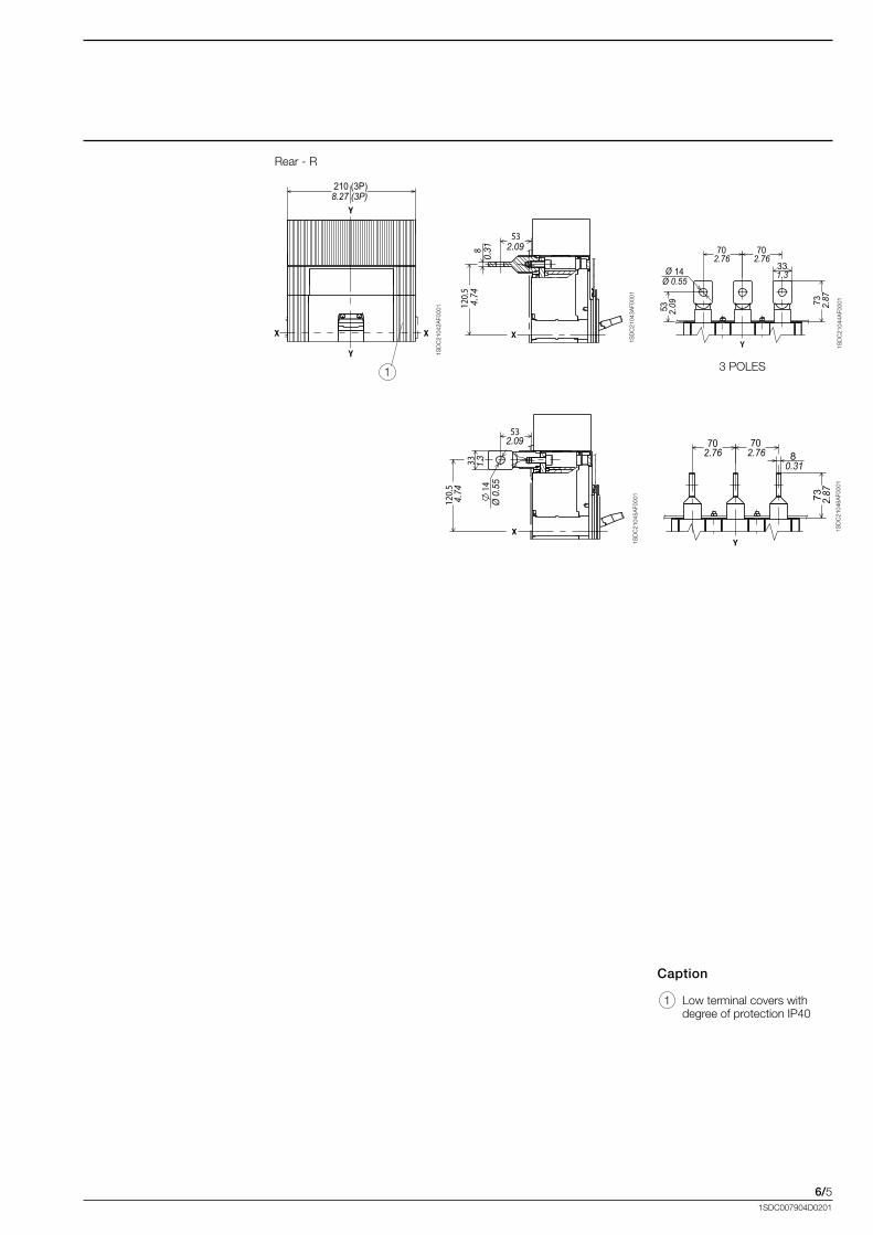
Rear.-.R
Caption
..1. Low.terminal.covers.with.
. degree.of.protection.IP40
3.POLES
73
33
7070
53
14
2.09
2.76 2.76
1.3
2.87
Ø 0.55Ø
87070
73 2.87
2.762.760.31
210 (3P)8.27 (3P)
53
812
0.5
2.09
4.74
0.31
53
14
120.5
33
2.09
4.74
1.3
Ø 0
.55

6/61SDC007904D0201
Overall dimensionsTmax.T6
1SD
C21
0J78
F000
1
1SD
C21
069A
F000
1
1SD
C21
070A
F000
1
140
120
8.5 - M8
214
144
77.5
77.5
2R5.51
4.72
0.33 - M8
8.43
5.67
3.05
3.05
0.08R
1SD
C21
071A
F000
1
Draw out circuit-breaker
Fixing.on.sheet
Caption
..1. Cradle
..2. Moving.part
..3. Lock.for.compartment..(available.on.request)
..4. Overall.dimensions.with..cabled.accessories.mounted.(SOR-C,.UVR-C)
Drilling templates of the compartment doorFlange for the compartment door
Drilling templates for support sheet
3
27.5 isolating distance1.08
84.5
140
5 0.20
≤ 2 190.5
196
167
145
208
295
5.71
8.19
11.6
135.5
≤ 0.08 7.5
7.72
6.57
1.4
0.123.
33
5.51
100.
25
173 3.
95
6.81
75.25
210
2.96
8.27
150
=
=148.5
89.5
43 14
96.5
200R min.
18.5
122
18
5.85
1.69 0.55
7.87R min.
4.8
0.71
32
5.91 3.
52 3.8
0.73
1.26
1SD
C21
067A
F000
1
1SD
C21
068A
F000
1470
210 (3P)
273
10.7
5
136.5123.55.374.86
77
144.
753.03
5.7
702.76
8.27 (3P)
2.76
4
6/71SDC007904D0201
1SD
C21
0J86
F000
1
1SD
C21
078A
F000
1
1SD
C21
0J89
F000
1
1SD
C21
077A
F000
1
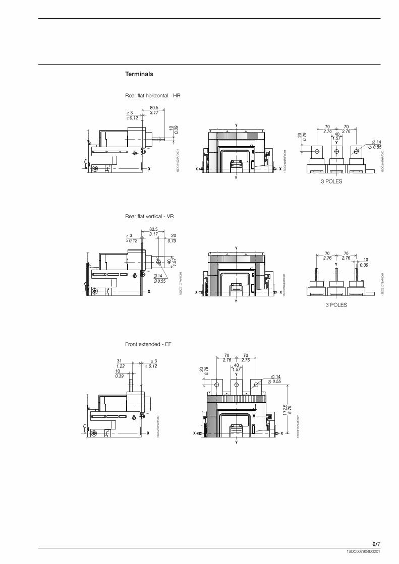
Rear.flat.horizontal.-.HR
Rear.flat.vertical.-.VR
3.POLES
3.POLES
Terminals
80.53.17
100.
39
30.12
40
14
2080.53.17
1.57
30.12 0.79
0.55
1SD
C21
075A
F000
1
1SD
C21
076A
F000
1
70
14
40200.
79
702.76
0.55
1.572.76
70 702.76
0.39
2.76 10
3
10
310.12
0.39
1.22
1SD
C21
073A
F000
1
1SD
C21
074A
F000
1
Front.extended.-.EF
70
172.
5
14
40
20
6.79
0.79
702.76
0.55
1.57
2.76
6/81SDC007904D0201
Overall dimensionsAccessories.for.Tmax.T6
1SD
C21
007B
F000
11S
DC
2100
9BF0
001
1SD
C21
010B
F000
1
1SD
C21
023B
F000
1
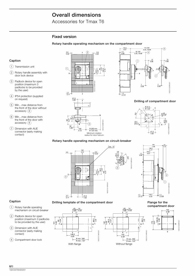
Fixed version
Caption
..1. Transmission.unit
..2. Rotary.handle.assembly.with.door.lock.device
..3. Padlock.device.for.open..position.(maximum.3..padlocks.to.be.provided..by.the.user)
..4. IP54.protection.(supplied..on.request)
..5. Min…max.distance.from..the.front.of.the.door.without..accessory...4
..6. Min…max.distance.from.. .the.front.of.the.door.with..accessory...4
..7. Dimension.with.AUE.
. connector.(early.making.contact)
Rotary handle operating mechanism on the compartment door
Drilling of compartment door
Caption
..1. Rotary.handle.operating.mechanism.on.circuit-breaker
..2. Padlock.device.for.open.
. position.(maximum.3.padlocks.to.be.provided.by.the.user)
..3. Dimension.with.AUE.
. connector.(early.making.
. contact)
..4. Compartment.door.lock
Rotary handle operating mechanism on circuit-breaker
Drilling template of the compartment door Flange for the compartment door
Minimum.rotation.radius.for.door.fulcrum
With.flange Without.flange
1SD
C21
006B
F000
1
R 200 min.
41.51.63
1054.13 R 7.87 min.
321.26
83 3.27 50 1.
97
1SD
C21
008B
F000
1
45
R 31.5R 1.24
Ø 5Ø 0.2
41.51.63
42.5
1.67
Ø 50Ø 1.97
43 14
90
151
148.5
R min. 200
1.69 0.55
5.94 3.
54
5.85
R min. 7.87
96.5
3.8
43 14
85.5
142
142
R min. 200
1.69 0.55
5.59 3.
37
5.59
R min. 7.87
96.5
3.8
152
173 10
0.25
5.98
6.81 3.
95
1SD
C21
013B
F000
1
1SD
C21
014B
F000
1
5.50.22
5.50.22
2.70.11
42.5
1.67
82 3.23
105.
54.
15
2
103.5
146.5
190 33
≥ 3 140.5 ≤ 2
7.48
5.77
4.07
1.3
≥ 0.12 ≤ 0.085.53
1.50.06
Det..“A”
Ø 4
2
Ø 0
.16
1SD
C21
011B
F000
1
1SD
C21
012B
F000
1
5.55.51405.51
0.22
2.70.11
41.51.63
42.5
1.67 84
.53.
3314
05.
51
3
103.54.07
110..5004.33..19.68
85..5003.35..19.68
250.98
250.98
20.08
20.08
30.12
1.50.06
6/91SDC007904D0201
1SD
C21
024B
F000
1
1SD
C21
025B
F000
1
1SD
C21
026B
F000
1
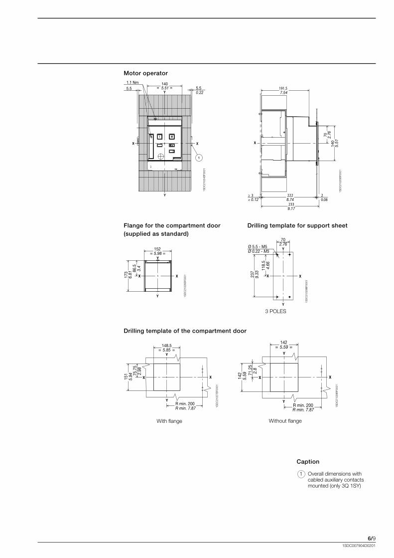
Motor operator
Caption
..1. Overall.dimensions.with.cabled.auxiliary.contacts.mounted.(only.3Q.1SY).
Flange for the compartment door (supplied as standard)
Drilling template of the compartment door
With.flange Without.flange
= =152
173 86
.5
5.98
6.81
3.4
= =
151
148.5
R min. 200
5.94
5.85
R min. 7.87
75.7
52.
98
= =
142
142
R min. 200
5.59
5.59
R min. 7.87
71.2
52.
8
1SD
C21
028B
F000
1
1SD
C21
027B
F000
1
70
237
Ø 5.5 - M5 2.76
Ø 0.22 - M5 9.
33
118.
54.
66
1SD
C21
029B
F000
1
Drilling template for support sheet
3.POLES
140= =5.5 5.5
0.225.51
1.1 Nm
3 222 2
233
191.5
140
70
7.54
2.76
5.51
8.74
9.17
0.12 0.08
6/101SDC007904D0201
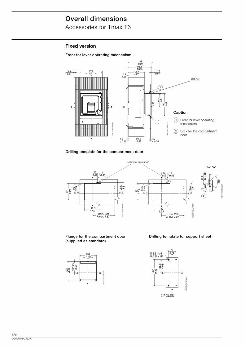
Overall dimensionsAccessories.for.Tmax.T6
1SD
C21
032B
F000
1
1SD
C21
036B
F000
1
70
237
Ø 5.5 - M5 2.76Ø 0.22 - M5
9.33
118.
54.
66
1SD
C21
037B
F000
1
Caption
..1. Front.for.lever.operating.mechanism
..2. Lock.for.the.compartment.door.
Front for lever operating mechanism
Flange for the compartment door (supplied as standard)
Drilling template for the compartment door
Drilling template for support sheet
3.POLES
Det..“A”
Det. “A”
Drilling.of.details.“A”
1SD
C21
031B
F000
1
Ø 4
Ø 0
.16
= =152
173 10
0.25
5.98
6.81 3.
95
1SD
C21
033B
F000
1
43 14
90
151
148.5
R min. 200
1.69 0.55
5.94 3.
54
5.85
R min. 7.87
96.5
3.8
1SD
C21
034B
F000
1
43 14
85.5
142
142
R min. 200
1.69 0.55
5.59 3.
37
5.59
R min. 7.87
96.5
3.8
1SD
C21
035B
F000
1
Fixed version
2.7 140= =0.11 5.51
103.5
146.5
158
17
140
84.5
6.22
146.5
4.07 0.67
3.33
5.51
≥ 3 140.5 ≤ 25.53≥ 0.12 ≤ 0.08
1.50.06
6/111SDC007904D0201
150
=
=148.5
32.5
122
18
3275.2
5
5.9 2.
96
1.28
1.26
0.71
4.8
R min. 200R min. 7.87
5.85
241
281.5
27.5 isolating distance
70
5.51
37
1.08
9.49
1.46
2.76
0.22
≥ 3 ≤ 2≥ 0.12 ≤ 0.08
11.08
27210.71
1SD
C21
040B
F000
1
1SD
C21
041B
F000
1
1SD
C21
042B
F000
1
1SD
C21
039B
F000
1
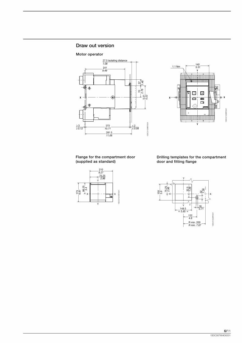
Draw out version
Motor operator
Flange for the compartment door (supplied as standard)
Drilling templates for the compartment door and fitting flange
75.25
210
173 86
.25
6.81
3.4
2.96
8.27
1405.511.1 Nm
6/121SDC007904D0201
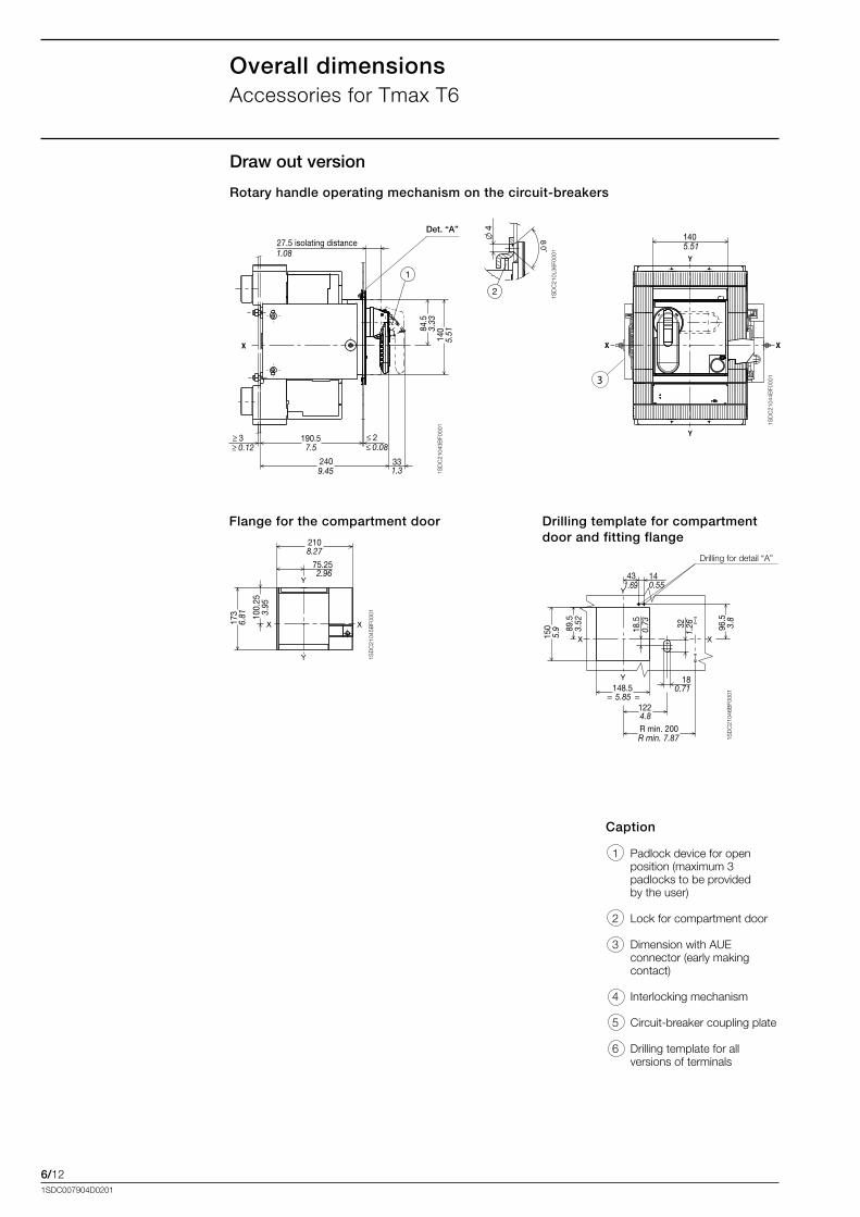
Overall dimensionsAccessories.for.Tmax.T6
4
2
1SD
C21
0L36
F000
1
Det. “A”
1SD
C21
045B
F000
1
1SD
C21
046B
F000
1
Caption
..1. Padlock.device.for.open..position.(maximum.3..padlocks.to.be.provided.. .by.the.user)
..2. Lock.for.compartment.door.
..3. Dimension.with.AUE..connector.(early.making.contact)
..4. Interlocking.mechanism
..5. Circuit-breaker.coupling.plate
..6. Drilling.template.for.all..versions.of.terminals
Rotary handle operating mechanism on the circuit-breakers
Flange for the compartment door Drilling template for compartment door and fitting flange
190.5
240
84.5
140
33
1
27.5 isolating distance1.08
≥ 3 ≤ 2≥ 0.12 ≤ 0.087.5
9.45 1.3
3.33
5.51
1SD
C21
043B
F000
1 1SD
C21
044B
F000
1
75.25
210
173 10
0.25
6.81 3.
95
8.27
2.96
Drilling.for.detail.“A”
18.5
89.5
150
= =148.5
122
1832
5.9 1.26
0.71
4.8R min. 200R min. 7.87
5.85
43 141.69 0.55
96.5
3.8
3.52
0.73
Draw out version
140
3
5.51

6/131SDC007904D0201
1SD
C21
0L37
F000
11S
DC
210L
38F0
001
Insulation distances for installation in metallic cubicle
Minimum centre distance between two circuit-breakers side by side or superimposedFor.assembly.side.by.side.or.superimposed,.check.that.the.connection.busbars.or.cables.do.not.reduce.the.air.insulation.distance.
Minimum centre distance for two circuit-breakers side by side
Overall dimensionsDistances.to.be.respected.for.Tmax.T6
200.79
250.98
200.79
2108.27
6/141SDC007904D0201
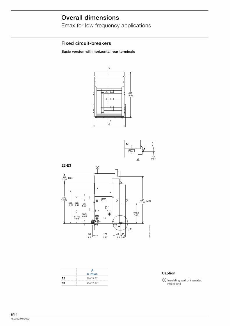
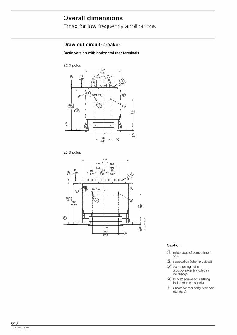
Overall dimensionsEmax.for.low.frequency.applications
Fixed circuit-breakers
Basic version with horizontal rear terminals
E2-E3
1SD
C20
0065
F020
1
Caption
. 1. Insulating.wall.or.insulated.metal.wall.
A 3 Poles
E2 296/11.65’’
E3 404/15.91’’
6/151SDC007904D0201
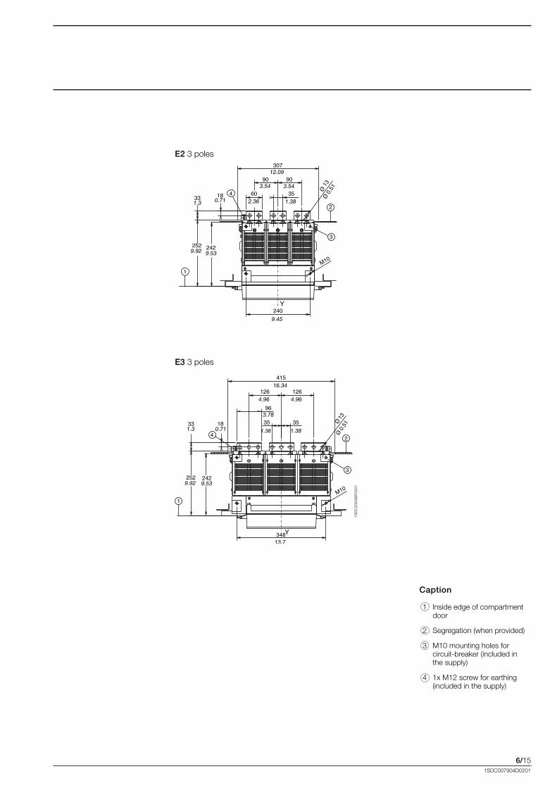
1SD
C20
0066
F020
1
E2.3.poles
E3 3.poles
Caption
. 1. Inside.edge.of.compartment.door.
. 2. Segregation.(when.provided)
. 3. M10.mounting.holes.for..circuit-breaker.(included.in...the.supply)..
. 4. 1x.M12.screw.for.earthing.(included.in.the.supply).
6/161SDC007904D0201
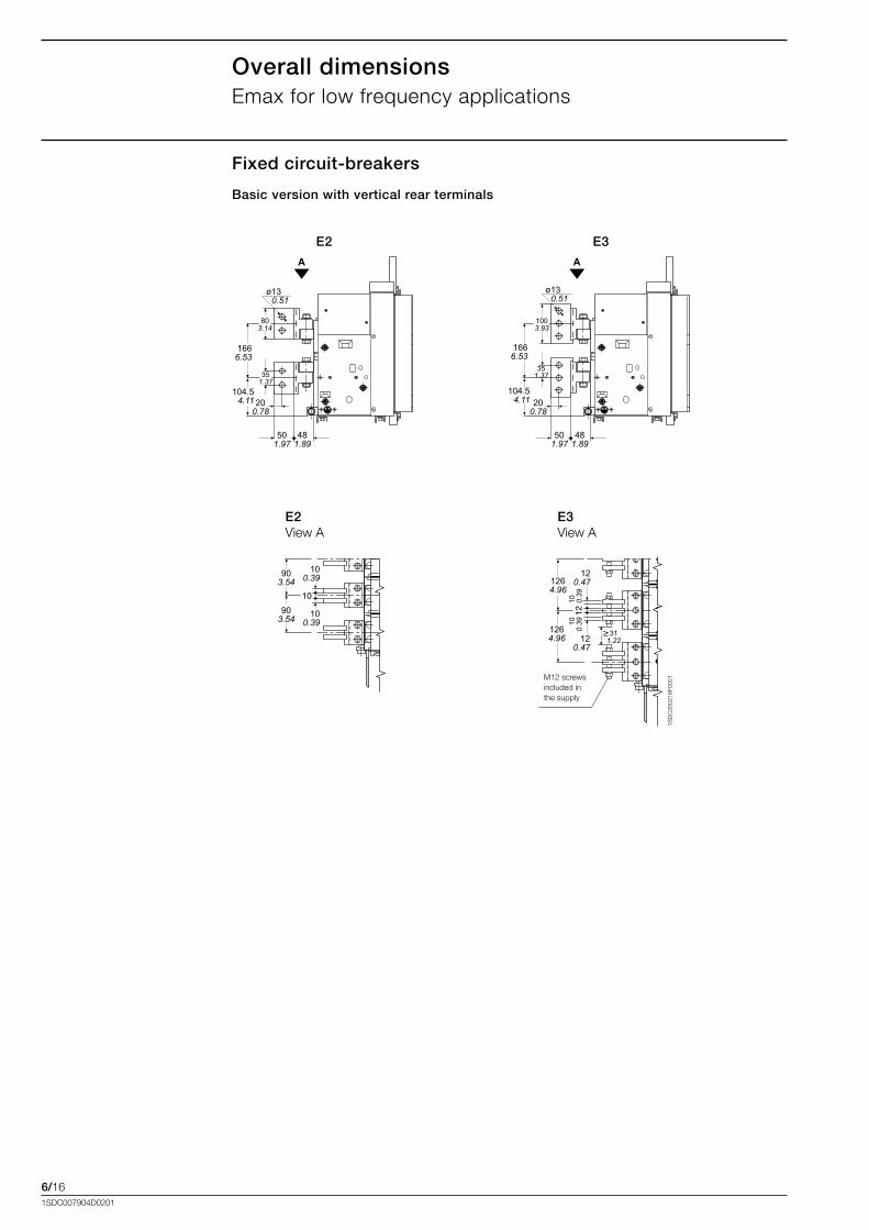
E2 E3
1SD
C20
0216
F000
1
E2View.A
E3View.A
M12.screws.included.in.the.supply
903.54
903.54 10
0.39
1264.96
1264.96
120.47
120.47
10 0.39
100.
39
104.54.11
501.97
481.89
351.37
803.14
1003.93
130.51
100.39
311.22
130.51
501.97
481.89
200.78
1666.53
351.37
104.54.11
1666.53
200.78
Overall dimensionsEmax.for.low.frequency.applications
Fixed circuit-breakers
Basic version with vertical rear terminals
6/171SDC007904D0201
Basic version with horizontal rear terminals
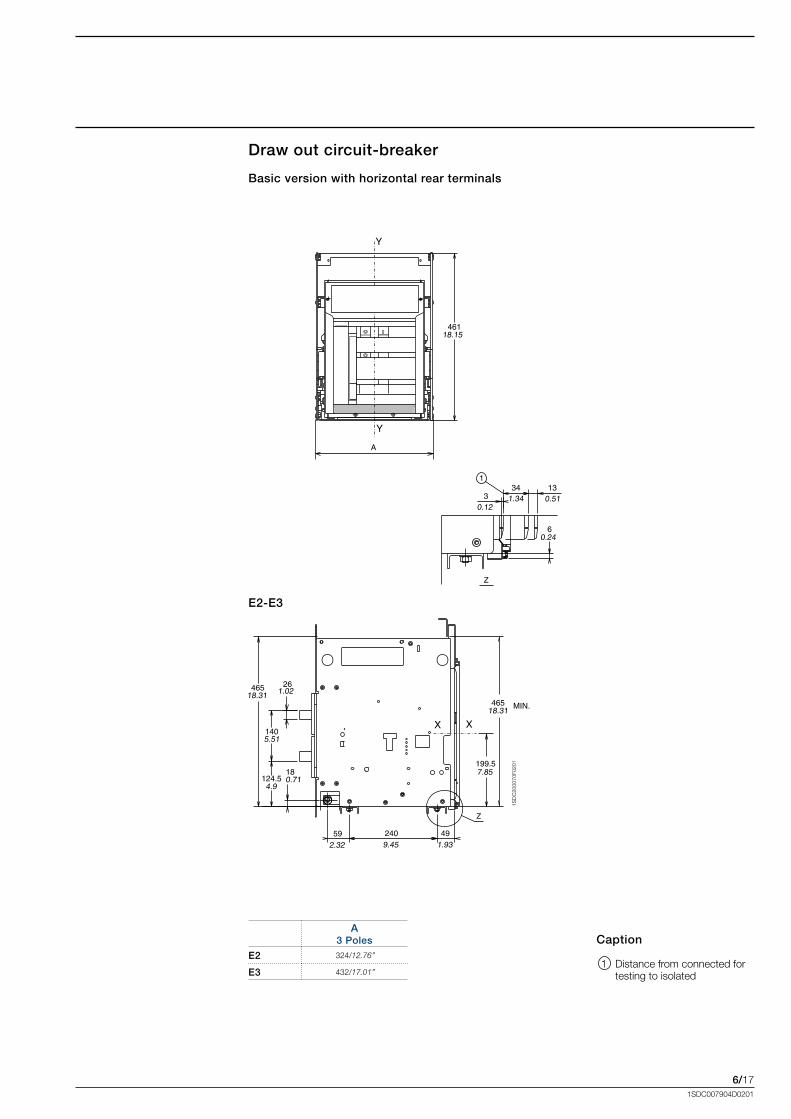
Draw out circuit-breaker
E2-E3
1SD
C20
0070
F020
1
Caption
. 1. Distance.from.connected.for.testing.to.isolated
A 3 Poles
E2 324/12.76’’
E3 432/17.01’’
6/181SDC007904D0201
1SD
C20
0071
F020
1
E2 3.poles
E3 3.poles
Caption
. 1. Inside.edge.of.compartment.door.
. 2. Segregation.(when.provided)
. 3. M8.mounting.holes.for.. .circuit-breaker.(included.in...the.supply)..
. 4. 1x.M12.screws.for.earthing.(included.in.the.supply).
. 5. 4.holes.for.mounting.fixed.part.(standard)
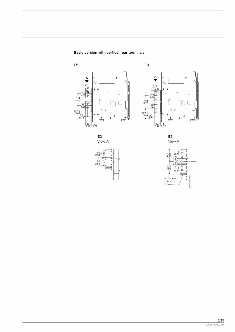
Overall dimensionsEmax.for.low.frequency.applications
Draw out circuit-breaker
Basic version with horizontal rear terminals
6/191SDC007904D0201
Basic version with vertical rear terminals
E2 E3
1SD
C20
0224
F000
1
M12.screwsincluded.in.the.supply..
E2View.A
E3View.A
903.54
903.54
100.39
100.39
1264.96
1264.96
120.47
120.47
10 0.39
100.
39
1144.49
137.55.41
501.97
30.12
501.97
30.12
1345.27
127.55.01 20
0.7820
0.78
351.37
803.14
351.37
1003.93
130.51
130.51
6/201SDC007904D0201
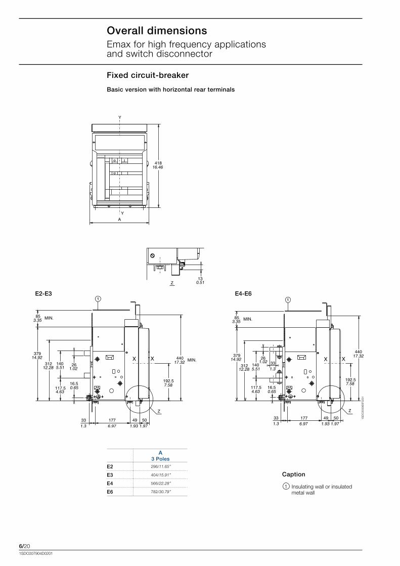
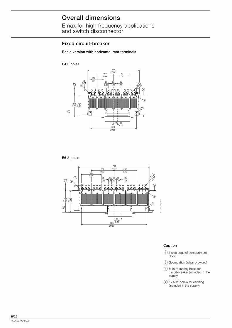
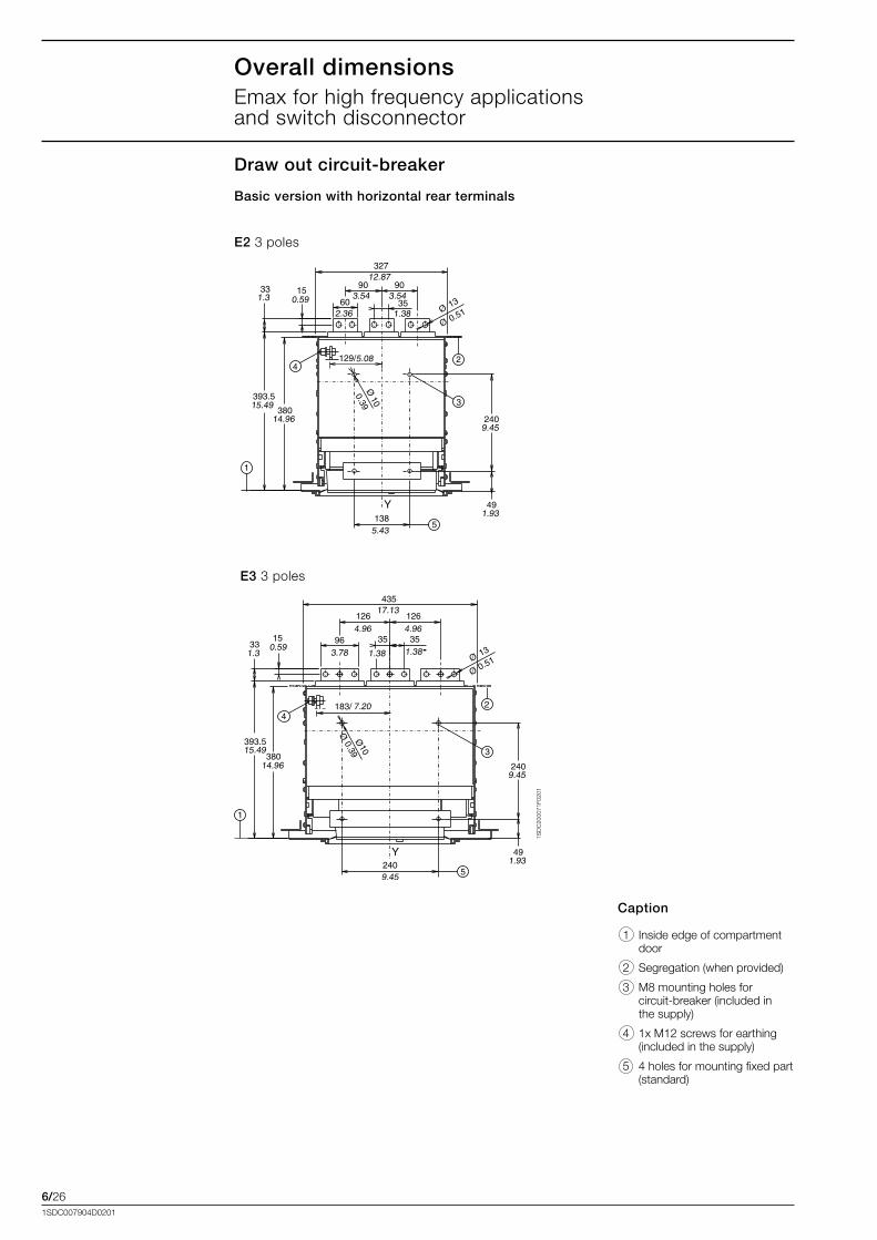
Overall dimensionsEmax.for.high.frequency.applications.. . . .and.switch.disconnector
Fixed circuit-breaker
Basic version with horizontal rear terminals
E2-E3
1SD
C20
0065
F020
1
Caption
. 1. Insulating.wall.or.insulated.metal.wall.
A 3 Poles
E2 296/11.65’’
E3 404/15.91’’
E4 566/22.28’’
E6 782/30.79’’
E4-E6

6/211SDC007904D0201
1SD
C20
0066
F020
1
E2.3.poles
E3 3.poles
Caption
. 1. Inside.edge.of.compartment.door.
. 2. Segregation.(when.provided)
. 3. M10.mounting.holes.for..circuit-breaker.(included.in...the.supply)..
. 4. 1x.M12.screw.for.earthing.(included.in.the.supply).
6/221SDC007904D0201
Overall dimensionsEmax.for.high.frequency.applications.. . . .and.switch.disconnector
Fixed circuit-breaker
Basic version with horizontal rear terminals
1SD
C20
0067
F020
1
E4 3.poles
E6 3.poles
Caption
. 1. Inside.edge.of.compartment.door.
. 2. Segregation.(when.provided)
. 3. M10.mounting.holes.for.. .circuit-breaker.(included.in..the.supply)..
. 4. 1x.M12.screw.for.earthing.(included.in.the.supply).
6/231SDC007904D0201
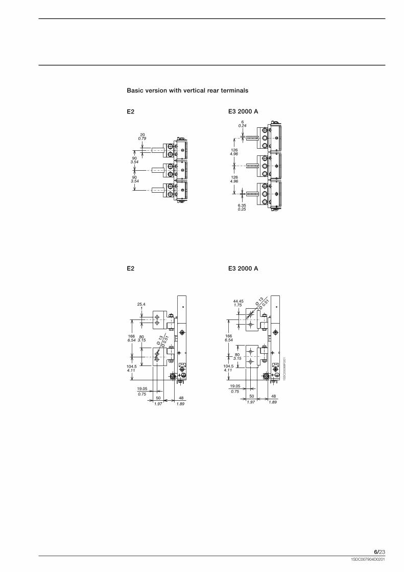
E2 E3 2000 A
E2 E3 2000 A
1SD
C20
0068
F020
1
Basic version with vertical rear terminals
6/241SDC007904D0201
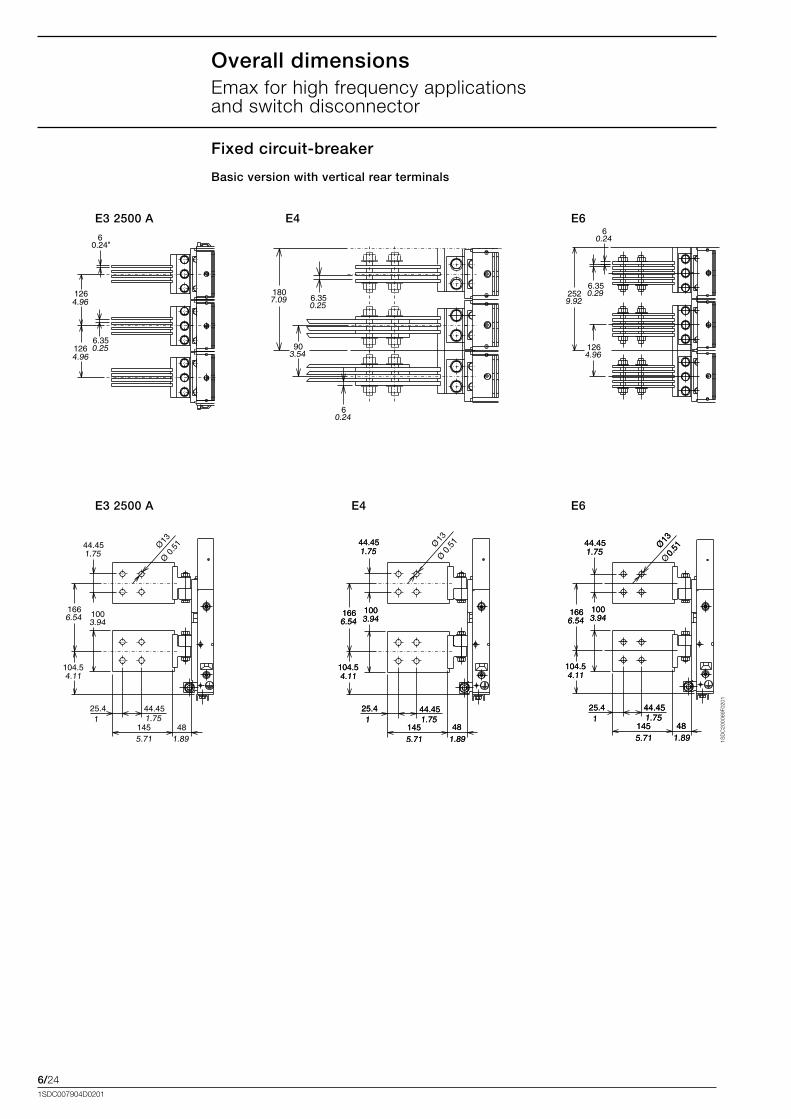
E3 2500 A E4 E6
E3 2500 A E4 E6
1SD
C20
0069
F020
1
Overall dimensionsEmax.for.high.frequency.applications.. . . .and.switch.disconnector
Fixed circuit-breaker
Basic version with vertical rear terminals
6/251SDC007904D0201
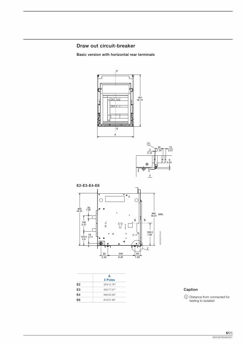
Basic version with horizontal rear terminals
Draw out circuit-breaker
E2-E3-E4-E6
1SD
C20
0070
F020
1
Caption
. 1. Distance.from.connected.for.testing.to.isolated
A 3 Poles
E2 324/12.76’’
E3 432/17.01’’
E4 594/23.39’’
E6 810/31.89’’
6/261SDC007904D0201
1SD
C20
0071
F020
1
E2 3.poles
E3 3.poles
Caption
. 1. Inside.edge.of.compartment.door.
. 2. Segregation.(when.provided)
. 3. M8.mounting.holes.for.. .circuit-breaker.(included.in...the.supply)..
. 4. 1x.M12.screws.for.earthing.(included.in.the.supply).
. 5. 4.holes.for.mounting.fixed.part.(standard)
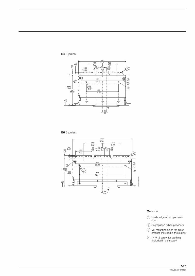
Overall dimensionsEmax.for.high.frequency.applications.. . . .and.switch.disconnector
Draw out circuit-breaker
Basic version with horizontal rear terminals
6/271SDC007904D0201
1SD
C20
0072
F020
1
E4 3.poles
E6 3.poles
Caption
. 1. Inside.edge.of.compartment.door.
. 2. Segregation.(when.provided)
. 3. M8.mounting.holes.for.circuit-breaker.(included.in.the.supply)..
. 4. 1x.M12.screw.for.earthing.(included.in.the.supply).
6/281SDC007904D0201
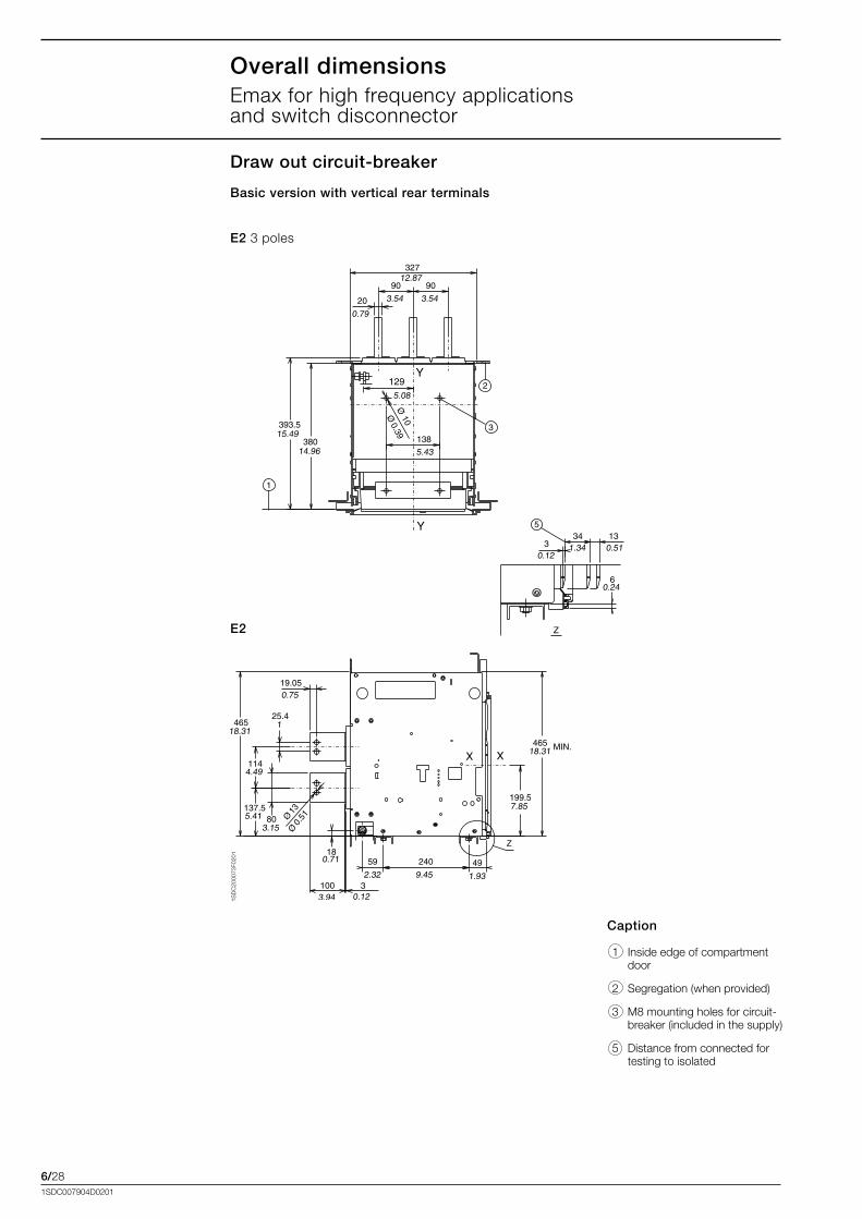
Overall dimensionsEmax.for.high.frequency.applications.. . . .and.switch.disconnector
Basic version with vertical rear terminals
Draw out circuit-breaker
1SD
C20
0073
F020
1
E2 3.poles
E2
Caption
. 1. Inside.edge.of.compartment.door.
. 2. Segregation.(when.provided)
. 3. M8.mounting.holes.for.circuit-breaker.(included.in.the.supply)..
. 5. Distance.from.connected.for.testing.to.isolated
6/291SDC007904D0201
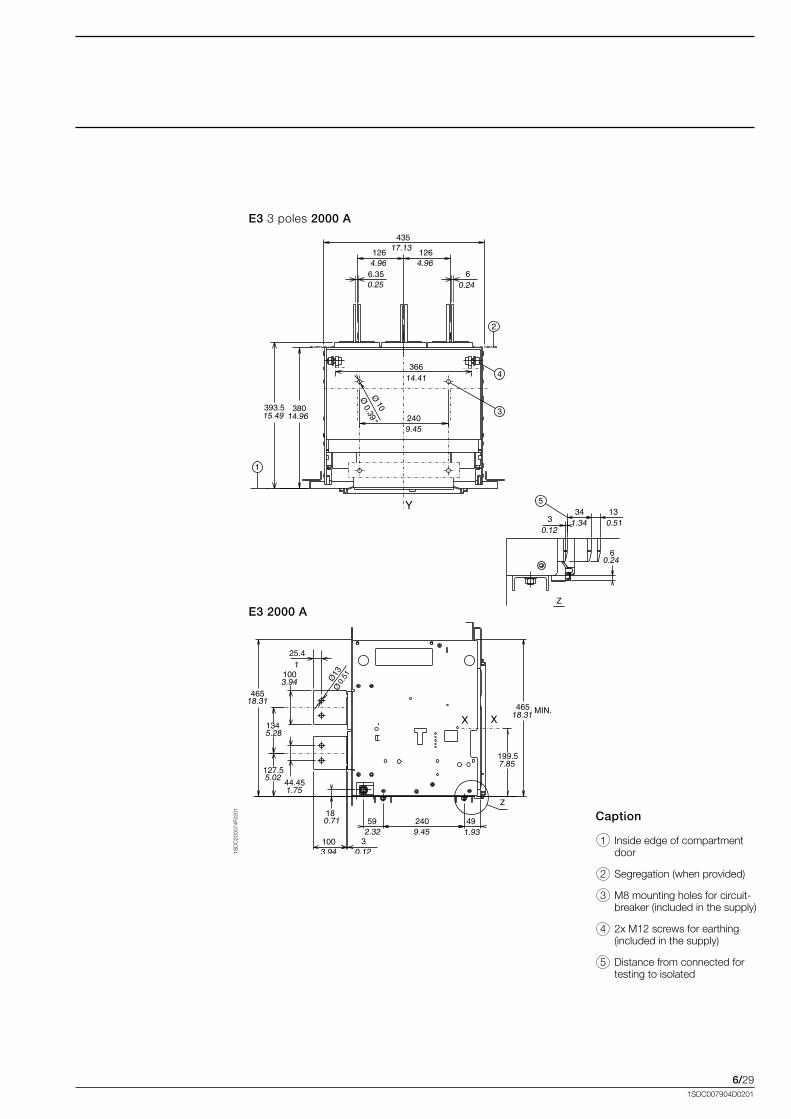
1SD
C20
0074
F020
1
E3 3.poles 2000 A
E3 2000 A
Caption
. 1. Inside.edge.of.compartment.door.
. 2. Segregation.(when.provided)
. 3. M8.mounting.holes.for.circuit-breaker.(included.in.the.supply)..
. 4. 2x.M12.screws.for.earthing.(included.in.the.supply).
. 5. Distance.from.connected.for.testing.to.isolated
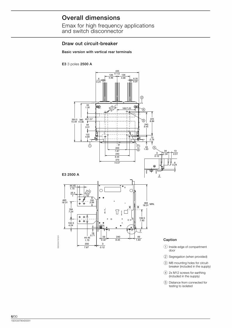
6/301SDC007904D0201
Overall dimensionsEmax.for.high.frequency.applications.. . . .and.switch.disconnector
Basic version with vertical rear terminals
Draw out circuit-breaker
1SD
C20
0075
F020
1
Caption
. 1. Inside.edge.of.compartment.door.
. 2. Segregation.(when.provided)
. 3. M8.mounting.holes.for.circuit-breaker.(included.in.the.supply)..
. 4. 2x.M12.screws.for.earthing.(included.in.the.supply).
. 5. Distance.from.connected.for.testing.to.isolated
E3 3.poles 2500 A
E3 2500 A
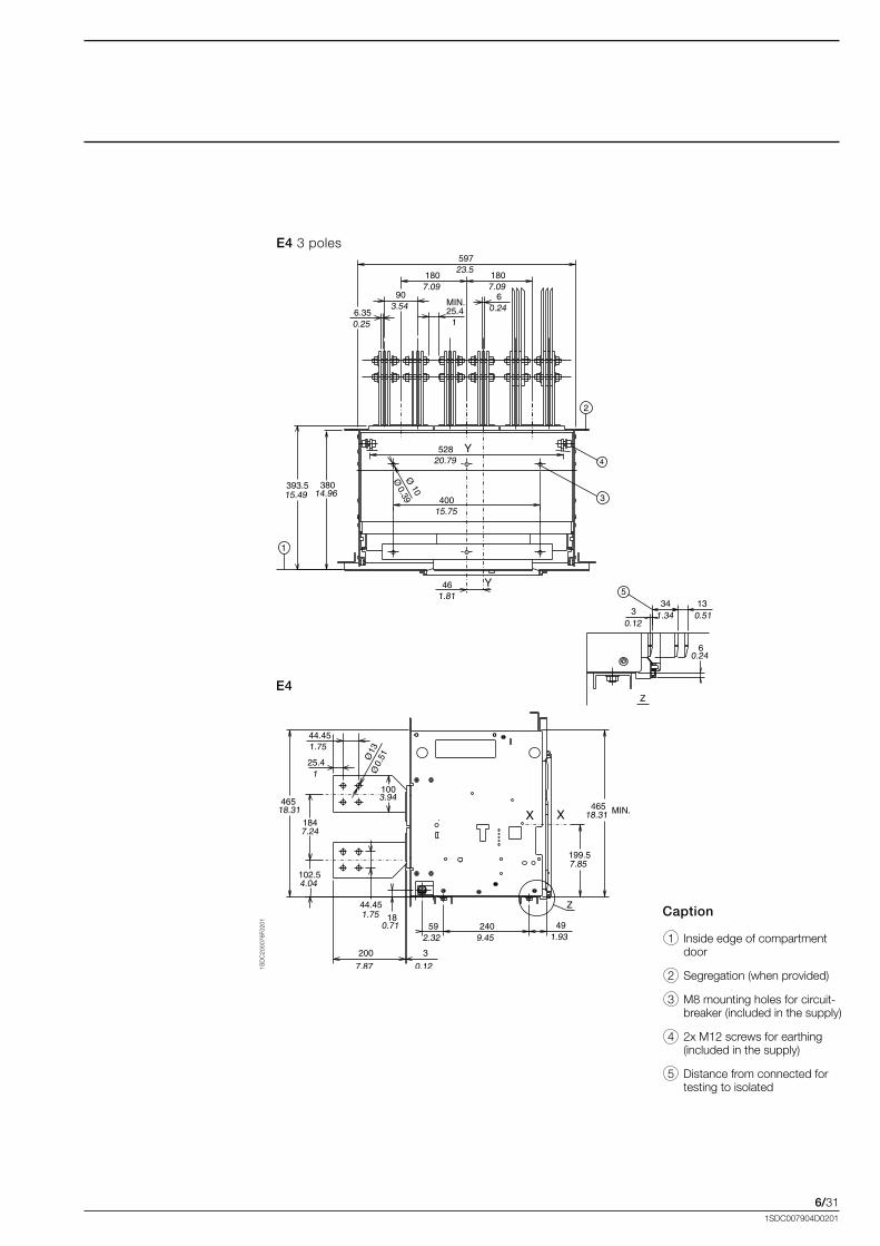
6/311SDC007904D0201
1SD
C20
0076
F020
1
E4.3.poles
E4
Caption
. 1. Inside.edge.of.compartment.door.
. 2. Segregation.(when.provided)
. 3. M8.mounting.holes.for.circuit-breaker.(included.in.the.supply)..
. 4. 2x.M12.screws.for.earthing.(included.in.the.supply).
. 5. Distance.from.connected.for.testing.to.isolated
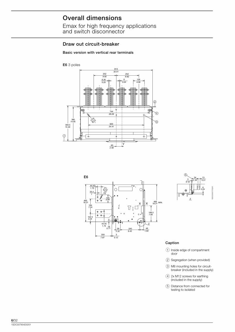
6/321SDC007904D0201
1SD
C20
0077
F020
1
E6 3.poles
E6
Caption
. 1. Inside.edge.of.compartment.door.
. 2. Segregation.(when.provided)
. 3. M8.mounting.holes.for.circuit-breaker.(included.in.the.supply)..
. 4. 2x.M12.screws.for.earthing.(included.in.the.supply).
. 5. Distance.from.connected.for.testing.to.isolated
Basic version with vertical rear terminals
Draw out circuit-breaker
Overall dimensionsEmax.for.high.frequency.applications.. . . .and.switch.disconnector
6/331SDC007904D0201
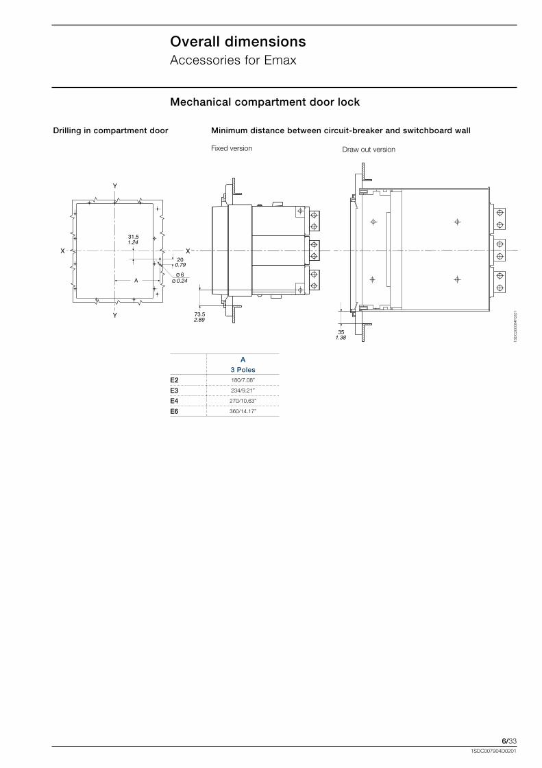
Mechanical compartment door lock
Overall dimensionsAccessories.for.Emax
X X
Y
Y
A
31,5
6
20
73.5
1.24
0.24ØØ
0.79
2.89
351.38
1SD
C20
0084
F020
1
Fixed.version Draw.out.version.
Minimum distance between circuit-breaker and switchboard wall Drilling in compartment door
A 3 Poles
E2 180/7.08”
E3 234/9.21”
E4 270/10,63”
E6 360/14.17”
6/341SDC007904D0201
“A”
2509.84
501.97
97,53.84
25510.04
“A”
B
Ø5,5
193,57.6252,3
2.06 183,57.22
42,51.67
1335,24
0.22Ø5
ØØ
1SD
C20
0087
F020
1
1SD
C20
0088
F020
1
“A”
2509.84
501.97
97,53.84
25510.04
“A”
1SD
C20
0091
F020
1
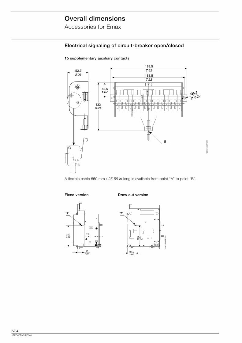
Electrical signaling of circuit-breaker open/closed
A.flexible.cable.650.mm./.25.59 in.long.is.available.from.point.“A”.to.point.“B”.
Fixed version Draw out version
15 supplementary auxiliary contacts
Overall dimensionsAccessories.for.Emax
6/351SDC007904D0201
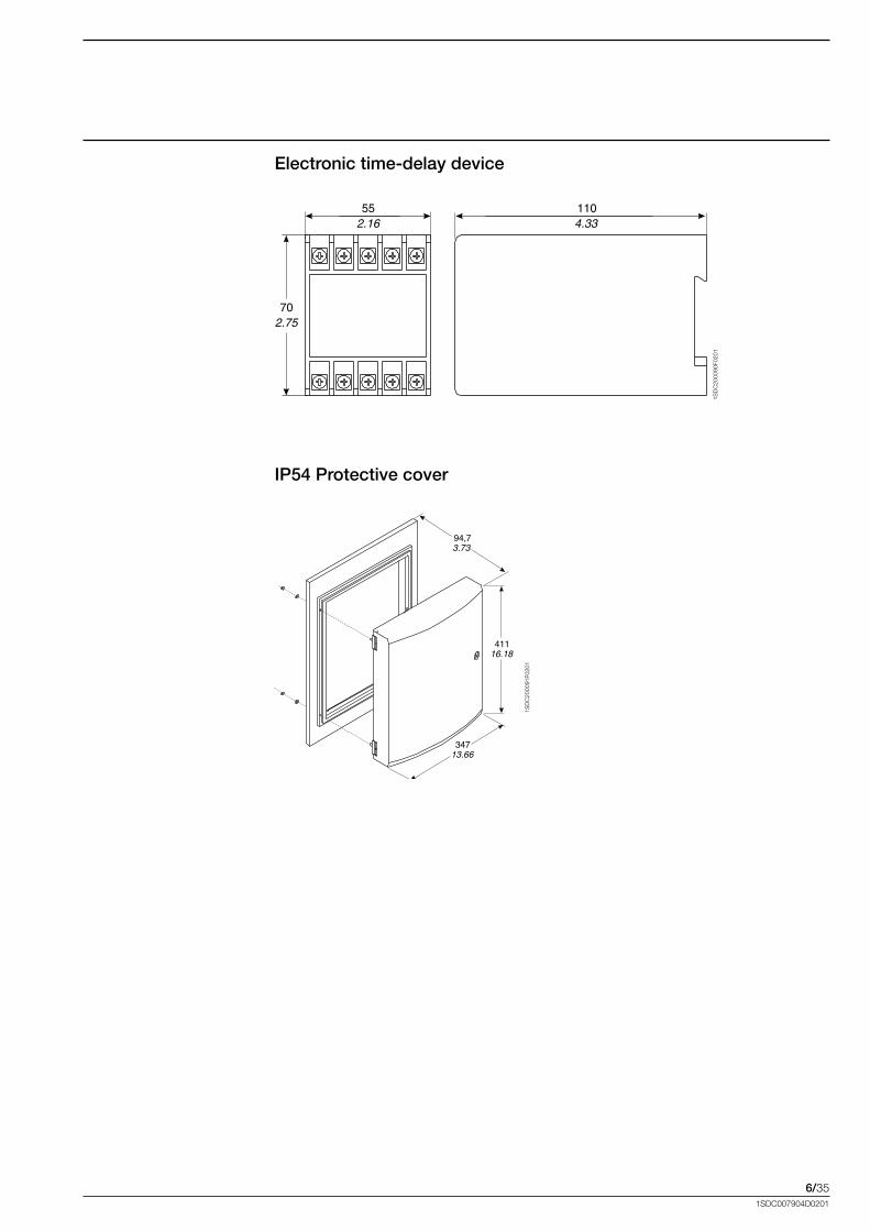
1104.33
552.16
702.75
1SD
C20
0090
F020
1
94,73.73
41116.18
34713.66
1SD
C20
0091
F020
1
Electronic time-delay device
IP54 Protective cover
6/361SDC007904D0201
38014.97
1505.9
50019.70
1SD
C20
0078
F020
1
1SD
C20
0079
F020
1
1SD
C20
0080
F020
1
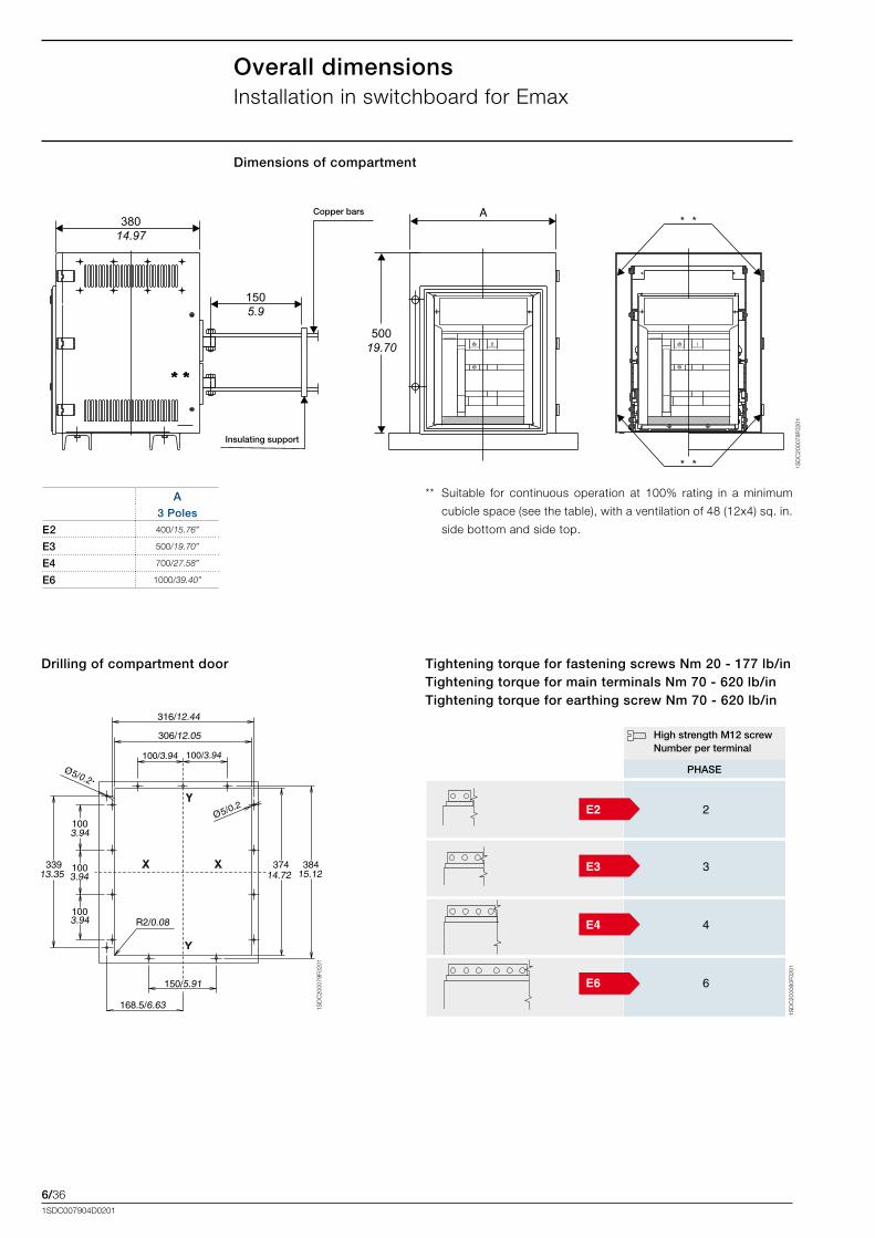
**. Suitable. for. continuous. operation. at. 100%. rating. in. a. minimum.
cubicle.space.(see.the.table),.with.a.ventilation.of.48.(12x4).sq..in..
side.bottom.and.side.top.
Copper bars
Insulating support
Tightening torque for fastening screws Nm 20 - 177 lb/in Tightening torque for main terminals Nm 70 - 620 lb/in Tightening torque for earthing screw Nm 70 - 620 lb/in
High strength M12 screw Number per terminal
PHASE
Drilling of compartment door
Dimensions of compartment
A 3 Poles
E2 400/15.76”
E3 500/19.70”
E4 700/27.58”
E6 1000/39.40”
Overall dimensionsInstallation.in.switchboard.for.Emax
7/11SDC007904D0201
Content
Reading information – Tmax T6 circuit-breakers ....................................................... 7/2
Reading information – Emax circuit-breakers............................................................. 7/4
Graphic symbols (IEC 60617 and CEI 3-14 ... 3-26 Standards)................................... 7/7
Circuit diagrams.
. Tmax.T6.circuit-breakers........................................................................................... 7/8
. Electrical.accessories.for.Tmax.T6.............................................................................. 7/9
. Emax.circuit-breakers................................................................................................7/12
. Electrical.accessories.for.Emax...................................................................................7/13
Circuit diagrams
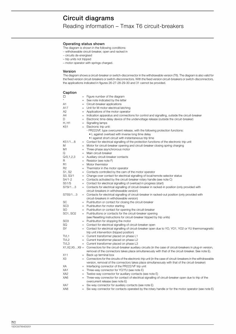
7/21SDC007904D0201
Circuit diagramsReading.information.–.Tmax.T6.circuit-breakers.
Operating status shownThe.diagram.is.shown.in.the.following.conditions:–.withdrawable.circuit-breaker,.open.and.racked.in–.circuits.de-energised–.trip.units.not.tripped–.motor.operator.with.springs.charged.
VersionThe.diagram.shows.a.circuit-breaker.or.switch-disconnector.in.the.withdrawable.version.(T6)..The.diagram.is.also.valid.for.the.fixed.version.circuit-breakers.or.switch-disconnectors..With.the.fixed.version.circuit-breakers.or.switch-disconnectors,.the.applications.indicated.in.figures.26-27-28-29-30.and.31.cannot.be.provided.
Caption.. =. Figure.number.of.the.diagram*.. =.. See.note.indicated.by.the.letterA1.. =.. Circuit-breaker.applicationsA17.. =.. Unit.for.M.motor.electrical.latchingA2.. =.. Applications.of.the.motor.operatorA4.. =.. Indication.apparatus.and.connections.for.control.and.signalling,.outside.the.circuit-breakerD.. =.. Electronic.time-delay.device.of.the.undervoltage.release.(outside.the.circuit-breaker)H,.H1.. =.. Signalling.lampsK51.. =.. Electronic.trip.unit:. . -.PR222VF,.type.overcurrent.release,.with.the.following.protection.functions:. . ...•.L.against.overload.with.inverse.long.time.delay. . ...•.I.against.short-circuit.with.instantaneous.trip.timeK51/1…8.. =.. Contact.for.electrical.signalling.of.the.protection.functions.of.the.electronic.trip.unitM.. =.. Motor.for.circuit-breaker.opening.and.circuit-breaker.closing.spring.chargingM1.. =.. Three-phase.asynchronous.motorQ.. =.. Main.circuit-breakerQ/0,1,2,3.. =.. Auxiliary.circuit-breaker.contactsR. =.. Resistor.(see.note.F)R1.. =.. Motor.thermistorR2.. =.. Thermistor.in.the.motor.operatorS1,.S2.. =.. Contacts.controlled.by.the.cam.of.the.motor.operatorS3,.S3/1.. =.. Change-over.contact.for.electrical.signalling.of.local/remote.selector.statusS4/1-2.. =.. Contacts.activated.by.the.circuit-breaker.rotary.handle.(see.note.C)S51/S.. =.. Contact.for.electrical.signalling.of.overload.in.progress.(start)S75I/1…3.. =.. Contacts.for.electrical.signalling.of.circuit-breaker.in.racked-in.position.(only.provided.with.. . circuit-breakers.in.withdrawable.version)S75S/1…3.. =.. Contacts.for.electrical.signalling.of.circuit-breaker.in.racked-out.position.(only.provided.with.. . circuit-breakers.in.withdrawable.version)SC.. =.. Pushbutton.or.contact.for.closing.the.circuit-breakerSC3.. =.. Pushbutton.for.motor.startingSO.. =.. Pushbutton.or.contact.for.opening.the.circuit-breakerSO1,.SO2.. =.. Pushbuttons.or.contacts.for.the.circuit-breaker.opening.. . . . .
(see.Resetting.instructions.for.circuit-breaker.tripped.by.trip.units)SO3.. =.. Pushbutton.for.stopping.the.motorSQ.. =.. Contact.for.electrical.signalling.of.circuit-breaker.openSY.. =.. Contact.for.electrical.signalling.of.circuit-breaker.open.due.to.YO,.YO1,.YO2.or.YU.thermomagnetic.. . trip.unit.intervention.(tripped.position)TI/L1.. =.. Current.transformer.placed.on.phase.L1TI/L2.. =.. Current.transformer.placed.on.phase.L2TI/L3.. =.. Current.transformer.placed.on.phase.L3X1,X2,X5…X9..=.. Connectors.for.the.circuit-breaker.auxiliary.circuits.(in.the.case.of.circuit-breakers.in.plug-in.version,.. . removal.of.the.connectors.takes.place.simultaneously.with.that.of.the.circuit-breaker..See.note.E).X11.. =.. Back-up.terminal.boxX3.. =.. Connectors.for.the.circuits.of.the.electronic.trip.unit.(in.the.case.of.circuit-breakers.in.the.withdrawable.
version,.removal.of.the.connectors.takes.place.simultaneously.with.that.of.the.circuit-breaker)XA.. =.. Interfacing.connector.of.the.PR222/VF.trip.unitXA1.. =.. Three-way.connector.for.YO/YU.(see.note.E)XA2.. =.. Twelve-way.connector.for.auxiliary.contacts.(see.note.E)XA6.. =.. Three-way.connector.for.contact.of.electrical.signalling.of.circuit-breaker.open.due.to.trip.of.the.. . overcurrent.release.(see.note.E)XA7.. =.. Six-way.connector.for.auxiliary.contacts.(see.note.E)XA8.. =.. Six-way.connector.for.contacts.operated.by.the.rotary.handle.or.for.the.motor.operator.(see.note.E)
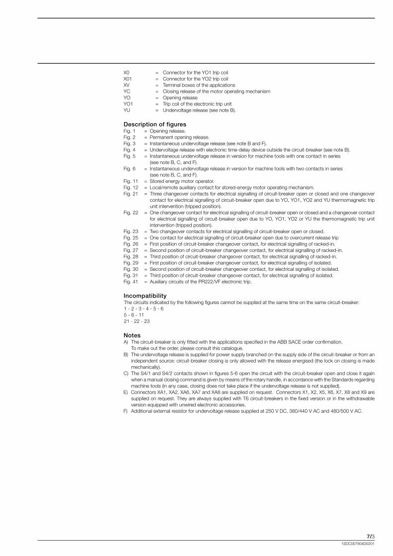
7/31SDC007904D0201
X0.. =.. Connector.for.the.YO1.trip.coilX01.. =.. Connector.for.the.YO2.trip.coilXV.. =.. Terminal.boxes.of.the.applicationsYC.. =.. Closing.release.of.the.motor.operating.mechanismYO.. =.. Opening.releaseYO1.. =.. Trip.coil.of.the.electronic.trip.unitYU.. =.. Undervoltage.release.(see.note.B).
Description of figuresFig..1.. =. Opening.release.Fig..2.. =..Permanent.opening.release.Fig..3.. =..Instantaneous.undervoltage.release.(see.note.B.and.F).Fig..4.. =..Undervoltage.release.with.electronic.time-delay.device.outside.the.circuit-breaker.(see.note.B).Fig..5. =..Instantaneous.undervoltage.release.in.version.for.machine.tools.with.one.contact.in.series.. . (see.note.B,.C,.and.F).Fig..6.. =..Instantaneous.undervoltage.release.in.version.for.machine.tools.with.two.contacts.in.series.. . (see.note.B,.C,.and.F).Fig..11.. =..Stored.energy.motor.operator.Fig..12.. =..Local/remote.auxiliary.contact.for.stored-energy.motor.operating.mechanism.Fig..21.. =..Three.changeover.contacts.for.electrical.signalling.of.circuit-breaker.open.or.closed.and.one.changeover.
contact.for.electrical.signalling.of.circuit-breaker.open.due.to.YO,.YO1,.YO2.and.YU.thermomagnetic.trip.unit.intervention.(tripped.position).
Fig..22.. =..One.changeover.contact.for.electrical.signalling.of.circuit-breaker.open.or.closed.and.a.changeover.contact.for.electrical.signalling.of.circuit-breaker.open.due.to.YO,.YO1,.YO2.or.YU.the.thermomagnetic.trip.unit.intervention.(tripped.position).
Fig..23.. =..Two.changeover.contacts.for.electrical.signalling.of.circuit-breaker.open.or.closed.Fig..25.. =..One.contact.for.electrical.signalling.of.circuit-breaker.open.due.to.overcurrent.release.tripFig..26.. =..First.position.of.circuit-breaker.changeover.contact,.for.electrical.signalling.of.racked-in.Fig..27.. =..Second.position.of.circuit-breaker.changeover.contact,.for.electrical.signalling.of.racked-in.Fig..28. =..Third.position.of.circuit-breaker.changeover.contact,.for.electrical.signalling.of.racked-in.Fig..29.. =..First.position.of.circuit-breaker.changeover.contact,.for.electrical.signalling.of.isolated.Fig..30.. =..Second.position.of.circuit-breaker.changeover.contact,.for.electrical.signalling.of.isolated.Fig..31.. =..Third.position.of.circuit-breaker.changeover.contact,.for.electrical.signalling.of.isolated.Fig..41.. =..Auxiliary.circuits.of.the.PR222/VF.electronic.trip.
IncompatibilityThe.circuits.indicated.by.the.following.figures.cannot.be.supplied.at.the.same.time.on.the.same.circuit-breaker:1.-.2.-.3.-.4.-.5.-.65.-.6.-.1121.-.22.-.23.
NotesA)..The.circuit-breaker.is.only.fitted.with.the.applications.specified.in.the.ABB.SACE.order.confirmation... To.make.out.the.order,.please.consult.this.catalogue.B)..The.undervoltage.release.is.supplied.for.power.supply.branched.on.the.supply.side.of.the.circuit-breaker.or.from.an.
independent.source:.circuit-breaker.closing.is.only.allowed.with.the.release.energised.(the.lock.on.closing.is.made.mechanically).
C)..The.S4/1.and.S4/2.contacts.shown.in.figures.5-6.open.the.circuit.with.the.circuit-breaker.open.and.close.it.again.when.a.manual.closing.command.is.given.by.means.of.the.rotary.handle,.in.accordance.with.the.Standards.regarding.machine.tools.(in.any.case,.closing.does.not.take.place.if.the.undervoltage.release.is.not.supplied).
E)..Connectors.XA1,.XA2,.XA6,.XA7.and.XA8.are.supplied.on.request...Connectors.X1,.X2,.X5,.X6,.X7,.X8.and.X9.are.supplied.on.request..They.are.always.supplied.with.T6.circuit-breakers.in.the.fixed.version.or.in.the.withdrawable.version.equipped.with.unwired.electronic.accessories.
F).. Additional.external.resistor.for.undervoltage.release.supplied.at.250.V.DC,.380/440.V.AC.and.480/500.V.AC.
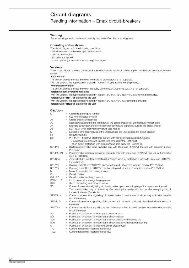
7/41SDC007904D0201
Circuit diagramsReading.information.–.Emax.circuit-breakers.
WarningBefore.installing.the.circuit-breaker,.carefully.read.notes.F.on.the.circuit.diagrams.
Operating status shownThe.circuit.diagram.is.for.the.following.conditions:-.withdrawable.circuit-breaker,.open.and.racked-in-.circuits.de-energised-.trip.units.not.tripped-.motor.operating.mechanism.with.springs.discharged.
VersionsThough.the.diagram.shows.a.circuit-breaker.in.withdrawable.version,.it.can.be.applied.to.a.fixed.version.circuit-breaker.as.well.Fixed versionThe.control.circuits.are.fitted.between.terminals.XV.(connector.X.is.not.supplied).With.this.version,.the.applications.indicated.in.figures.31A.and.32A.cannot.be.provided.Withdrawable versionThe.control.circuits.are.fitted.between.the.poles.of.connector.X.(terminal.box.XV.is.not.supplied).Version without overcurrent releaseWith.this.version,.the.applications.indicated.in.figures.13A,.14A,.42A,.45A,.46A,.47A.cannot.be.provided.Version with PR111/VF electronic trip unitWith.this.version,.the.applications.indicated.in.figures.42A,.45A,.46A,.47A.cannot.be.provided.Version with PR122/VF electronic trip unit
Caption.. =.. Circuit.diagram.figure.number*.. =.. See.note.indicated.by.letterA1.. =.. Circuit-breaker.accessoriesA3.. =.. Accessories.applied.to.the.fixed.part.of.the.circuit-breaker.(for.withdrawable.version.only)A4.. =.. Example.switchgear.and.connections.for.control.and.signalling,.outside.the.circuit-breakerAY.. =.. SOR.TEST.UNIT.Test/monitoring.Unit.(see.note.R)D.. =.. Electronic.time-delay.device.of.the.undervoltage.trip.unit,.outside.the.circuit-breakerF1.. =.. Delayed-trip.fuseK51.. =.. PR111/VF,.PR122/VF.electronic.trip.unit.with.the.following.protection.functions:. . -.L.overload.protection.with.inverse.long.time-delay.trip.-.setting.I1. . -.I.short-circuit.protection.with.instantaneous.time-delay.trip.-.setting.I3K51/IN1.. =.. Digital.programmable.input.(available.only.with.Uaux.and.PR122/VF.trip.unit.with.indicator.module.
PR120/K)K51/P1...P4. =.. Programmable.electrical.signalling. (available.only.with.Uaux.and.PR122/VF. trip.unit.with. indicator.
module.PR120/K)K51/SZin.. =.. Zone.selectivity:.input.for.protection.S.or.“direct”.input.for.protection.D.[only.with.Uaux..and.PR122/VF.
trip.unit.(DFin)]K51/YC.. =.. Closing.control.from.PR122/VF.electronic.trip.unit.with.communication.module.PR120/D-MK51/YO.. =.. Opening.control.from.PR122/VF.electronic.trip.unit.with.communication.module.PR120/D-MM.. =.. Motor.for.charging.the.closing.springs.Q.. =.. Circuit-breakerQ/1...27.. =.. Circuit-breaker.auxiliary.contactsS33M/1...3.. =.. Limit.contacts.for.spring-charging.motorS43.. =.. Switch.for.setting.remote/local.controlS51.. =.. Contact.for.electrical.signalling.of.circuit-breaker.open.due.to.tripping.of.the.overcurrent.trip.unit.. . The.circuit-breaker.may.be.closed.only.after.pressing.the.reset.pushbutton,.or.after.energizing.the.coil.
for.electrical.reset.(if.available).S75E/1...4.. =.. Contacts. for. electrical. signalling. of. circuit-breaker. in. racked-out. position. (only. with. withdrawable.
circuit-breakers)S75I/1...5.. =.. Contacts.for.electrical.signalling.of.circuit-breaker.in.racked-in.position.(only.with.withdrawable.circuit-
breakers)S75T/1..4.. =.. Contacts. for.electrical.signalling.of.circuit-breaker. in. test. isolated.position. (only.with.withdrawable.
circuit-breakers)SC.. =.. Pushbutton.or.contact.for.closing.the.circuit-breakerSO. =.. Pushbutton.or.contact.for.opening.the.circuit-breakerSO1.. =.. Pushbutton.or.contact.for.opening.the.circuit-breaker.with.delayed.tripSO2.. =.. Pushbutton.or.contact.for.opening.the.circuit-breaker.with.instantaneous.tripSR.. =.. Pushbutton.or.contact.for.electrical.circuit-breaker.resetTI/L1.. =.. Current.transformer.located.on.phase.L1TI/L2.. =.. Current.transformer.located.on.phase.L2
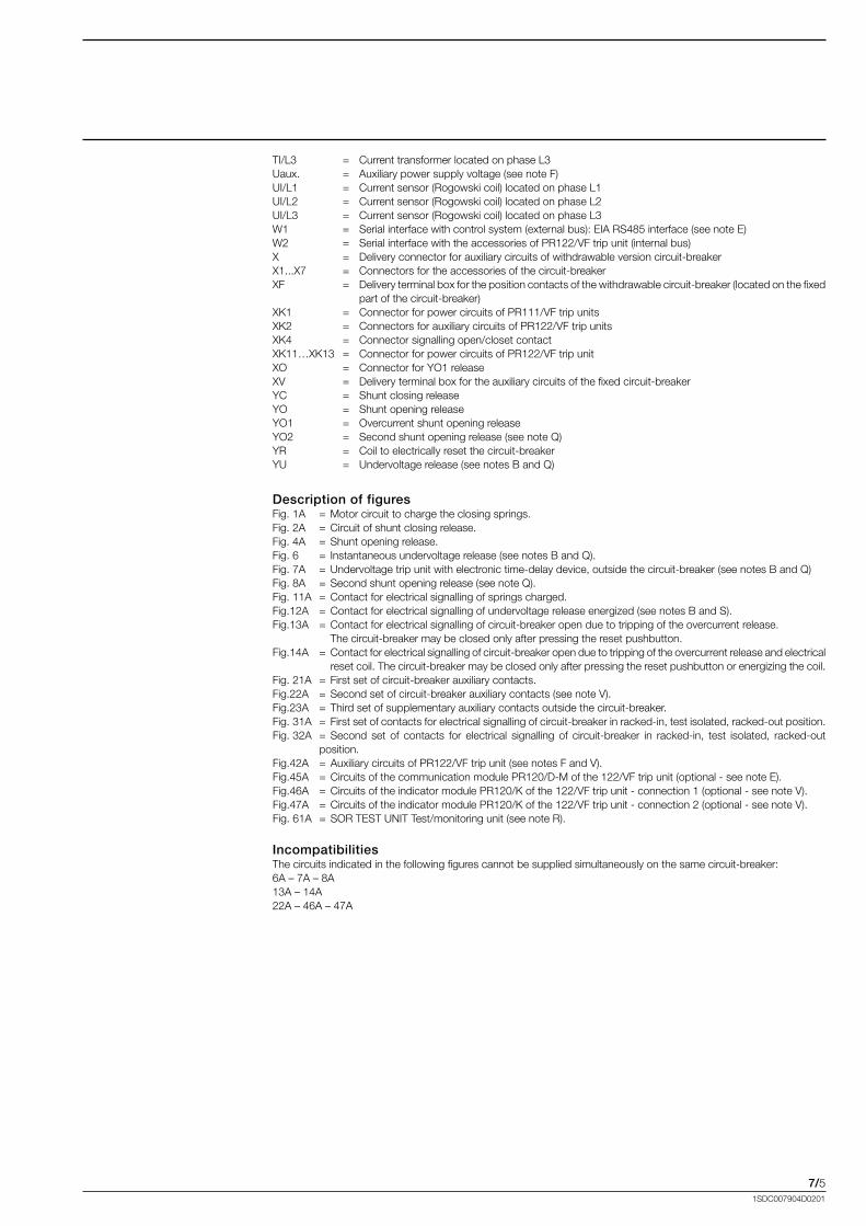
7/51SDC007904D0201
TI/L3.. =.. Current.transformer.located.on.phase.L3Uaux.. =.. Auxiliary.power.supply.voltage.(see.note.F)UI/L1.. =.. Current.sensor.(Rogowski.coil).located.on.phase.L1UI/L2.. =.. Current.sensor.(Rogowski.coil).located.on.phase.L2UI/L3.. =.. Current.sensor.(Rogowski.coil).located.on.phase.L3W1.. =.. Serial.interface.with.control.system.(external.bus):.EIA.RS485.interface.(see.note.E)W2.. =.. Serial.interface.with.the.accessories.of.PR122/VF.trip.unit.(internal.bus)X.. =.. Delivery.connector.for.auxiliary.circuits.of.withdrawable.version.circuit-breakerX1...X7.. =.. Connectors.for.the.accessories.of.the.circuit-breakerXF.. =.. Delivery.terminal.box.for.the.position.contacts.of.the.withdrawable.circuit-breaker.(located.on.the.fixed.
part.of.the.circuit-breaker)XK1.. =.. Connector.for.power.circuits.of.PR111/VF.trip.unitsXK2.. =.. Connectors.for.auxiliary.circuits.of.PR122/VF.trip.unitsXK4.. =.. Connector.signalling.open/closet.contactXK11…XK13.. =.. Connector.for.power.circuits.of.PR122/VF.trip.unitXO.. =.. Connector.for.YO1.releaseXV.. =.. Delivery.terminal.box.for.the.auxiliary.circuits.of.the.fixed.circuit-breakerYC.. =.. Shunt.closing.releaseYO.. =.. Shunt.opening.releaseYO1.. =.. Overcurrent.shunt.opening.releaseYO2.. =.. Second.shunt.opening.release.(see.note.Q)YR.. =.. Coil.to.electrically.reset.the.circuit-breakerYU.. =.. Undervoltage.release.(see.notes.B.and.Q)
Description of figuresFig..1A.. =..Motor.circuit.to.charge.the.closing.springs.Fig..2A.. =..Circuit.of.shunt.closing.release.Fig..4A.. =..Shunt.opening.release.Fig..6.. =..Instantaneous.undervoltage.release.(see.notes.B.and.Q).Fig..7A.. =..Undervoltage.trip.unit.with.electronic.time-delay.device,.outside.the.circuit-breaker.(see.notes.B.and.Q)Fig..8A.. =..Second.shunt.opening.release.(see.note.Q).Fig..11A..=..Contact.for.electrical.signalling.of.springs.charged.Fig.12A.. =..Contact.for.electrical.signalling.of.undervoltage.release.energized.(see.notes.B.and.S).Fig.13A.. =..Contact.for.electrical.signalling.of.circuit-breaker.open.due.to.tripping.of.the.overcurrent.release... . The.circuit-breaker.may.be.closed.only.after.pressing.the.reset.pushbutton.Fig.14A.. =..Contact.for.electrical.signalling.of.circuit-breaker.open.due.to.tripping.of.the.overcurrent.release.and.electrical. . reset.coil..The.circuit-breaker.may.be.closed.only.after.pressing.the.reset.pushbutton.or.energizing.the.coil.Fig..21A..=..First.set.of.circuit-breaker.auxiliary.contacts.Fig.22A.. =..Second.set.of.circuit-breaker.auxiliary.contacts.(see.note.V).Fig.23A.. =..Third.set.of.supplementary.auxiliary.contacts.outside.the.circuit-breaker.Fig..31A..=..First.set.of.contacts.for.electrical.signalling.of.circuit-breaker.in.racked-in,.test.isolated,.racked-out.position.Fig..32A..=..Second. set. of. contacts. for. electrical. signalling. of. circuit-breaker. in. racked-in,. test. isolated,. racked-out.
position.Fig.42A.. =..Auxiliary.circuits.of.PR122/VF.trip.unit.(see.notes.F.and.V).Fig.45A.. =..Circuits.of.the.communication.module.PR120/D-M.of.the.122/VF.trip.unit.(optional.-.see.note.E).Fig.46A.. =..Circuits.of.the.indicator.module.PR120/K.of.the.122/VF.trip.unit.-.connection.1.(optional.-.see.note.V).Fig.47A.. =..Circuits.of.the.indicator.module.PR120/K.of.the.122/VF.trip.unit.-.connection.2.(optional.-.see.note.V).Fig..61A..=..SOR.TEST.UNIT.Test/monitoring.unit.(see.note.R).
IncompatibilitiesThe.circuits.indicated.in.the.following.figures.cannot.be.supplied.simultaneously.on.the.same.circuit-breaker:6A.–.7A.–.8A13A.–.14A22A.–.46A.–.47A
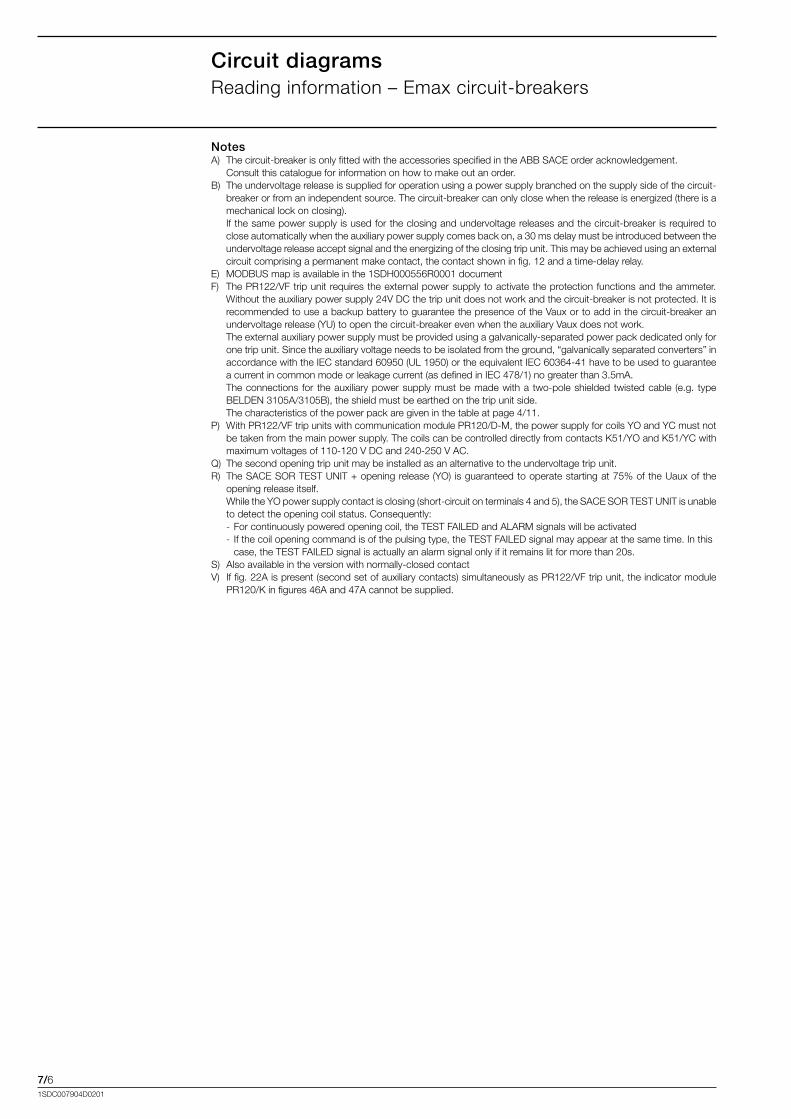
7/61SDC007904D0201
Circuit diagramsReading.information.–.Emax.circuit-breakers.
NotesA)..The.circuit-breaker.is.only.fitted.with.the.accessories.specified.in.the.ABB.SACE.order.acknowledgement.. Consult.this.catalogue.for.information.on.how.to.make.out.an.order.B)..The.undervoltage.release.is.supplied.for.operation.using.a.power.supply.branched.on.the.supply.side.of.the.circuit-
breaker.or.from.an.independent.source..The.circuit-breaker.can.only.close.when.the.release.is.energized.(there.is.a.mechanical.lock.on.closing).
. If.the.same.power.supply.is.used.for.the.closing.and.undervoltage.releases.and.the.circuit-breaker.is.required.to.close.automatically.when.the.auxiliary.power.supply.comes.back.on,.a.30.ms.delay.must.be.introduced.between.the.undervoltage.release.accept.signal.and.the.energizing.of.the.closing.trip.unit..This.may.be.achieved.using.an.external.circuit.comprising.a.permanent.make.contact,.the.contact.shown.in.fig..12.and.a.time-delay.relay.
E)..MODBUS.map.is.available.in.the.1SDH000556R0001.documentF).. The.PR122/VF.trip.unit.requires.the.external.power.supply.to.activate.the.protection.functions.and.the.ammeter..
Without.the.auxiliary.power.supply.24V.DC.the.trip.unit.does.not.work.and.the.circuit-breaker.is.not.protected..It.is.recommended.to.use.a.backup.battery.to.guarantee.the.presence.of.the.Vaux.or.to.add.in.the.circuit-breaker.an.undervoltage.release.(YU).to.open.the.circuit-breaker.even.when.the.auxiliary.Vaux.does.not.work.
. The.external.auxiliary.power.supply.must.be.provided.using.a.galvanically-separated.power.pack.dedicated.only.for.one.trip.unit..Since.the.auxiliary.voltage.needs.to.be.isolated.from.the.ground,.“galvanically.separated.converters”.in.accordance.with.the.IEC.standard.60950.(UL.1950).or.the.equivalent.IEC.60364-41.have.to.be.used.to.guarantee.a.current.in.common.mode.or.leakage.current.(as.defined.in.IEC.478/1).no.greater.than.3.5mA.
. The.connections. for. the.auxiliary.power.supply.must.be.made.with.a. two-pole.shielded.twisted.cable. (e.g.. type.BELDEN.3105A/3105B),.the.shield.must.be.earthed.on.the.trip.unit.side.
. The.characteristics.of.the.power.pack.are.given.in.the.table.at.page.4/11.P)..With.PR122/VF.trip.units.with.communication.module.PR120/D-M,.the.power.supply.for.coils.YO.and.YC.must.not.
be.taken.from.the.main.power.supply..The.coils.can.be.controlled.directly.from.contacts.K51/YO.and.K51/YC.with.maximum.voltages.of.110-120.V.DC.and.240-250.V.AC.
Q)..The.second.opening.trip.unit.may.be.installed.as.an.alternative.to.the.undervoltage.trip.unit.R)..The.SACE.SOR.TEST.UNIT.+.opening.release.(YO). is.guaranteed.to.operate.starting.at.75%.of.the.Uaux.of.the.
opening.release.itself.. While.the.YO.power.supply.contact.is.closing.(short-circuit.on.terminals.4.and.5),.the.SACE.SOR.TEST.UNIT.is.unable.
to.detect.the.opening.coil.status..Consequently:. -.For.continuously.powered.opening.coil,.the.TEST.FAILED.and.ALARM.signals.will.be.activated. -..If.the.coil.opening.command.is.of.the.pulsing.type,.the.TEST.FAILED.signal.may.appear.at.the.same.time..In.this. . case,.the.TEST.FAILED.signal.is.actually.an.alarm.signal.only.if.it.remains.lit.for.more.than.20s.S)..Also.available.in.the.version.with.normally-closed.contactV).. If.fig..22A.is.present.(second.set.of.auxiliary.contacts).simultaneously.as.PR122/VF.trip.unit,.the.indicator.module.
PR120/K.in.figures.46A.and.47A.cannot.be.supplied.
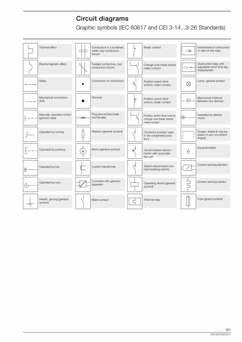
7/71SDC007904D0201
M
Circuit diagramsGraphic.symbols.(IEC.60617.and.CEI.3-14...3-26.Standards)
Break.contact
Change-over.break.before.make.contact
Position.switch.(limit.switch),.make.contact
Position.switch.(limit.switch),.break.contact
Position.switch.(limit.switch).change-over.break.before.make.contact
Contactor.(contact.open.in.the.unoperated.posi-tion)
Circuit-breaker.discon-nector.with.automatic.trip.unit
Switch-disconnector.(on-load.isolating.switch)
Operating.device.(general.symbol)
Thermal.relay
Thermal.effect
Electromagnetic.effect
Delay
Mechanical.connection.(link)
Manually.operated.control.(general.case)
Operated.by.turning
Operated.by.pushing
Operated.by.key
Operated.by.cam
Hearth,.groung.(general.symbol)
Conductors.in.a.screened.cable,.two.conductors.shown
Twisted.conductors,.two.conductors.shown
Connection.of.conductors
Terminal
Plug.and.socket.(male.and.female)
Resistor.(general.symbol)
Motor.(general.symbol)
Current.transformer
Converter.with.galvanic.separator
Make.contact
Instantaneous.overcurrent.or.rate-of-rise.relay
Overcurrent.relay.with.adjustable.short.time-lag.characteristic
Lamp,.general.symbol
Mechanical.interlock.between.two.devices
Operated.by.electric.motor
Screen,.shield.(it.may.be.drawn.in.any.convenient.shape)
Equipotentiality
Current.sensing.element
Current.sensing.resistor
Fuse.(gneral.symbol)

7/81SDC007904D0201
1SD
C21
0G02
F000
1
1SD
C21
0G02
F000
1
1SD
C21
0G03
F000
1
Circuit diagramsTmax.T6.circuit-breaker
Three-pole.circuit-breaker.with.thermomagnetic.trip.unit
Three-pole.circuit-breaker.with.PR222/VF.electronic.trip.unit.
PR222/VF
Three-pole.switch-disconnector.(on-load.isolating.switch).
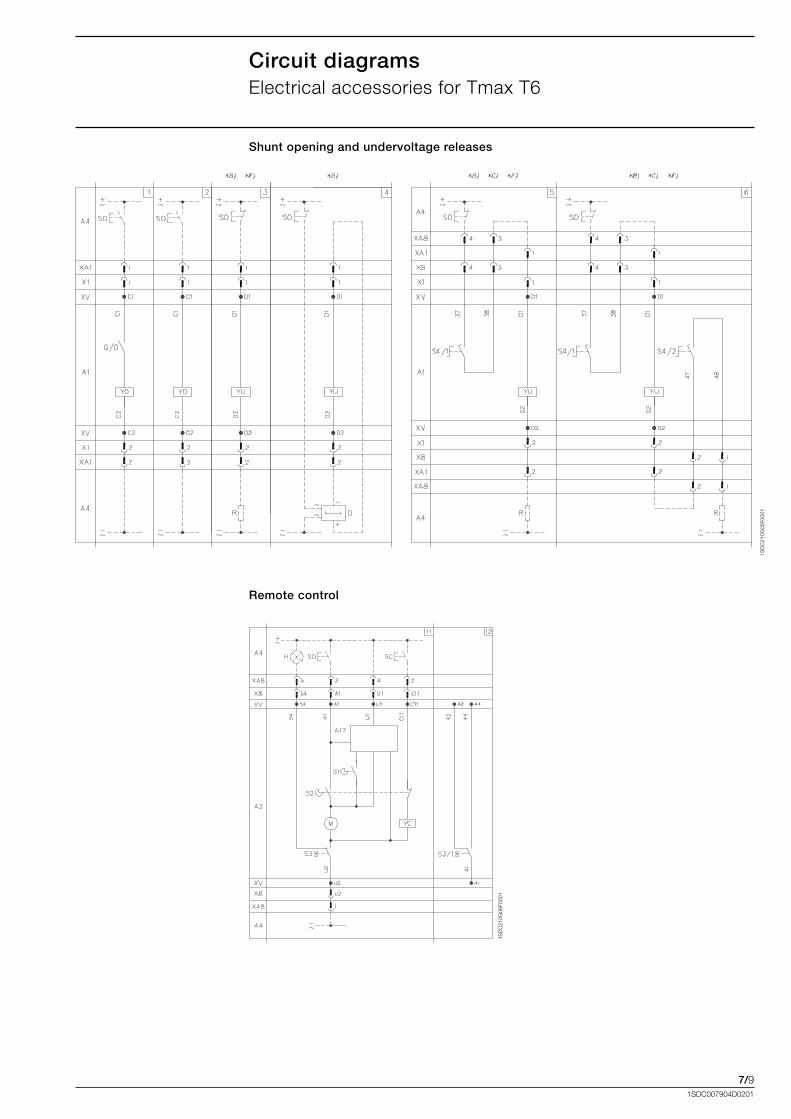
7/91SDC007904D0201
1SD
C21
0G05
F000
1
1SD
C21
0G06
F000
1
Circuit diagramsElectrical.accessories.for.Tmax.T6
Shunt opening and undervoltage releases
Remote control
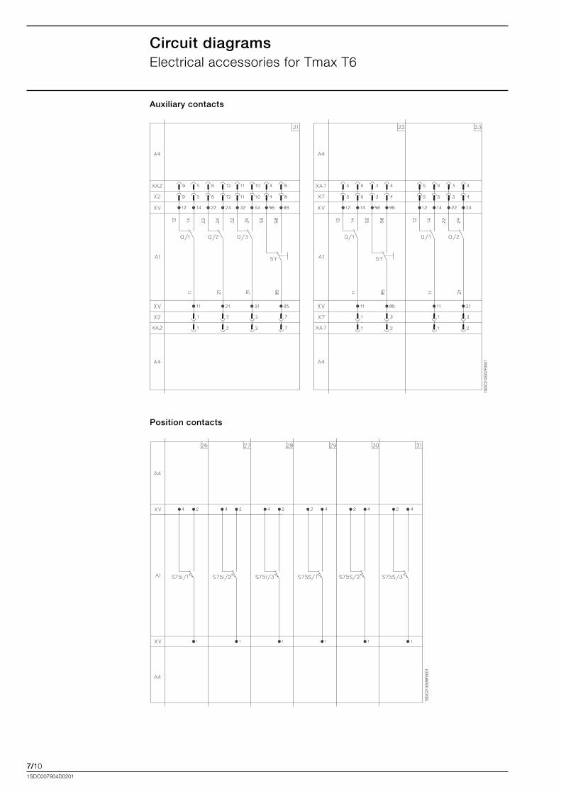
7/101SDC007904D0201
Circuit diagramsElectrical.accessories.for.Tmax.T6
1SD
C21
0G07
F000
1
1SD
C21
0G08
F000
1
Auxiliary contacts
Position contacts
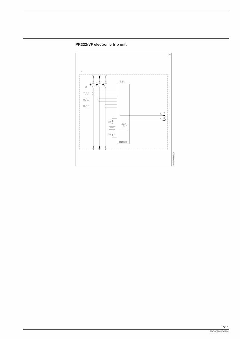
7/111SDC007904D0201
PR222/VF
1SD
C21
0G09
F000
1
PR222/VF electronic trip unit
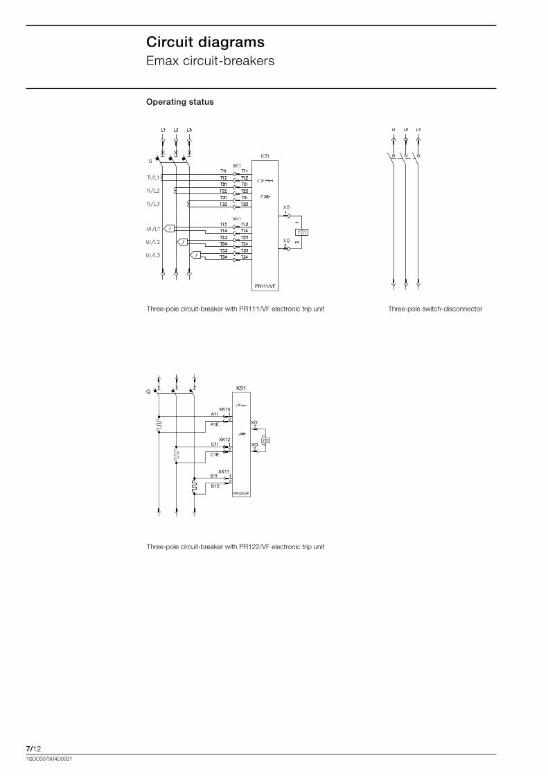
7/121SDC007904D0201
Circuit diagramsEmax.circuit-breakers
PR111/VF
Operating status
Three-pole.circuit-breaker.with.PR111/VF.electronic.trip.unit Three-pole.switch-disconnector
B1E
B1IXK11
12
A1I
A1E
12
1
XO
XO
Q
>>>
2
XK10
K51
>
1
Y01
2
PR122/VF
C1I
C1E
12
XK12
Three-pole.circuit-breaker.with.PR122/VF.electronic.trip.unit
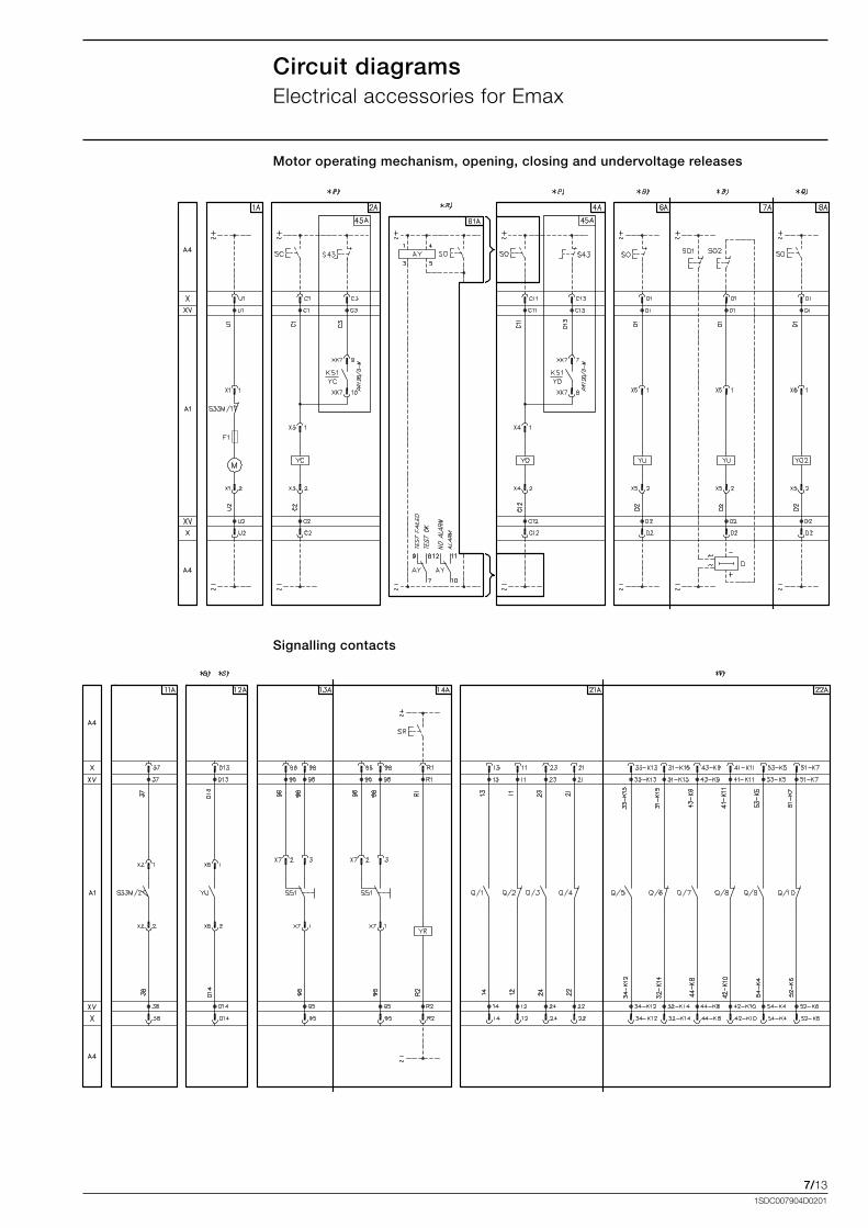
7/131SDC007904D0201
Circuit diagramsElectrical.accessories.for.Emax
Motor operating mechanism, opening, closing and undervoltage releases
Signalling contacts
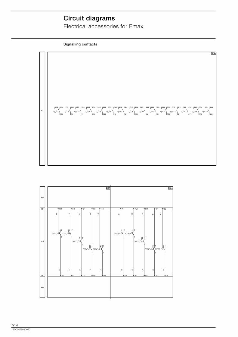
7/141SDC007904D0201
Circuit diagramsElectrical.accessories.for.Emax
Signalling contacts

7/151SDC007904D0201
VF
Auxiliary circuit of the PR122/VF trip unites
Communication module PR120/D-M
VF
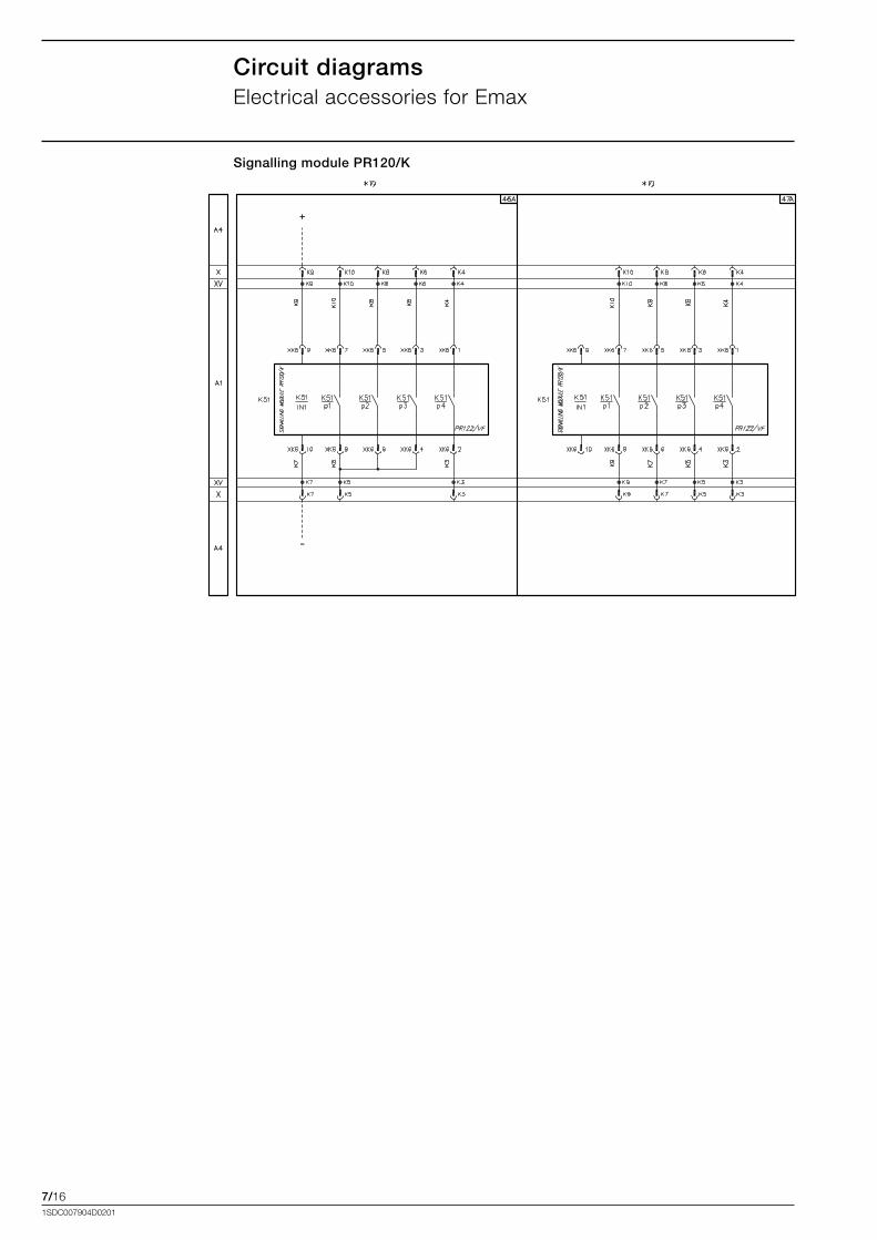
7/161SDC007904D0201
Signalling module PR120/K
Circuit diagramsElectrical.accessories.for.Emax
+
VF VF
8/11SDC007904D0201
Content
Tmax VF circuit-breakers.................................................................................................... 8/2
Tmax fixed parts and conversion kits............................................................................... 8/3
Accessories for Tmax.......................................................................................................... 8/4
Emax VF Circuit-breakers...................................................................................................8/10
Emax fixed parts...................................................................................................................8/11
Accessories for Emax..........................................................................................................8/13
Ordering codes
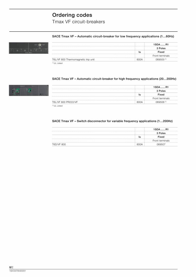
8/21SDC007904D0201
Ordering codesTmax.VF.circuit-breakers
1SDA ...... R1
3 Poles
Iu Fixed
Front.terminals
T6L/VF.800.Thermomagnetic.trip.unit 800A 069505.(1)
(1).UL.Listed
SACE Tmax VF – Automatic circuit-breaker for low frequency applications (1…60Hz)
SACE Tmax VF – Automatic circuit-breaker for high frequency applications (20…200Hz)
1SDA ...... R1
3 Poles
Iu Fixed
Front.terminals
T6L/VF.800.PR222/VF 800A 069506.(1)
(1).UL.Listed
SACE Tmax VF – Switch disconnector for variable frequency applications (1…200Hz)
1SDA ...... R1
3 Poles
Iu Fixed
Front.terminals
T6D/VF.800 800A 069507
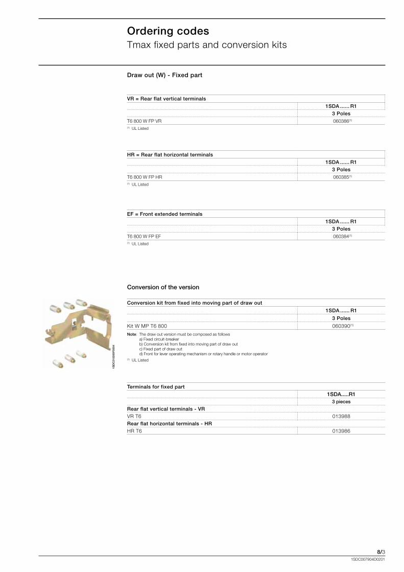
8/31SDC007904D0201
Draw out (W) - Fixed part
VR = Rear flat vertical terminals1SDA ...... R1
3 PolesT6.800.W.FP.VR ..060386(1)
(1)..UL.Listed
HR = Rear flat horizontal terminals1SDA ...... R1
3 PolesT6.800.W.FP.HR ..060385(1)
(1)..UL.Listed
Ordering codesTmax.fixed.parts.and.conversion.kits
Conversion of the version
Conversion kit from fixed into moving part of draw out
1SDA ...... R1
3 Poles
Kit.W.MP.T6.800 ..060390(1)
Note:. The.draw.out.version.must.be.composed.as.follows. . . . .. a).Fixed.circuit-breaker. . . .. b).Conversion.kit.from.fixed.into.moving.part.of.draw.out. . . .. c).Fixed.part.of.draw.out. . . .. d).Front.for.lever.operating.mechanism.or.rotary.handle.or.motor.operator. . .(1)..UL.Listed
1SD
C21
0200
F00
04
Terminals for fixed part
1SDA.....R13 pieces
Rear flat vertical terminals - VRVR.T6 013988Rear flat horizontal terminals - HRHR.T6 013986
EF = Front extended terminals1SDA ...... R1
3 PolesT6.800.W.FP.EF ..060384(1)
(1)..UL.Listed
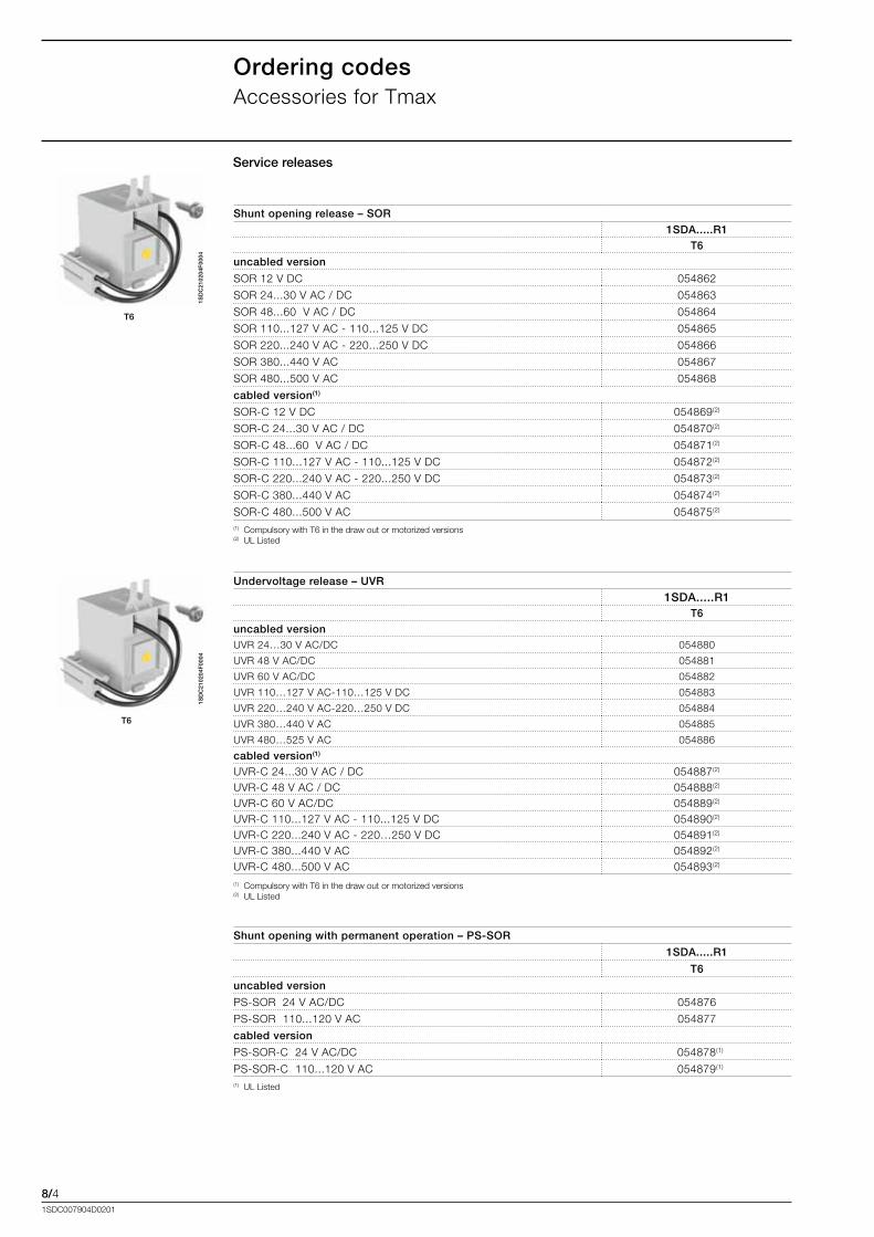
8/41SDC007904D0201
Ordering codesAccessories.for.Tmax
1SD
C21
0204
F00
04
T6
Shunt opening release – SOR1SDA.....R1
T6
uncabled version
SOR.12.V.DC 054862
SOR.24...30.V.AC./.DC 054863
SOR.48...60..V.AC./.DC 054864
SOR.110...127.V.AC.-.110...125.V.DC 054865
SOR.220...240.V.AC.-.220...250.V.DC 054866
SOR.380...440.V.AC 054867
SOR.480...500.V.AC 054868
cabled version(1)
SOR-C.12.V.DC 054869(2)
SOR-C.24...30.V.AC./.DC 054870(2)
SOR-C.48...60..V.AC./.DC 054871(2)
SOR-C.110...127.V.AC.-.110...125.V.DC 054872(2)
SOR-C.220...240.V.AC.-.220...250.V.DC 054873(2)
SOR-C.380...440.V.AC 054874(2)
SOR-C.480...500.V.AC 054875(2)
(1)..Compulsory.with.T6.in.the.draw.out.or.motorized.versions(2)..UL.Listed
Service releases
1SD
C21
0204
F00
04
T6
Undervoltage release – UVR
1SDA.....R1T6
uncabled versionUVR.24…30.V.AC/DC 054880
UVR.48.V.AC/DC 054881
UVR.60.V.AC/DC 054882
UVR.110…127.V.AC-110…125.V.DC. 054883
UVR.220…240.V.AC-220…250.V.DC. 054884
UVR.380…440.V.AC. 054885
UVR.480…525.V.AC. 054886
cabled version(1)
UVR-C.24...30.V.AC./.DC 054887(2)
UVR-C.48.V.AC./.DC 054888(2)
UVR-C.60.V.AC/DC 054889(2)
UVR-C.110...127.V.AC.-.110...125.V.DC 054890(2)
UVR-C.220...240.V.AC.-.220…250.V.DC 054891(2)
UVR-C.380...440.V.AC 054892(2)
UVR-C.480...500.V.AC 054893(2)
(1)..Compulsory.with.T6.in.the.draw.out.or.motorized.versions(2)..UL.Listed
Shunt opening with permanent operation – PS-SOR
1SDA.....R1
T6
uncabled version
PS-SOR..24.V.AC/DC 054876
PS-SOR..110...120.V.AC 054877
cabled version
PS-SOR-C..24.V.AC/DC ..054878(1)
PS-SOR-C..110...120.V.AC ..054879(1)
(1)..UL.Listed
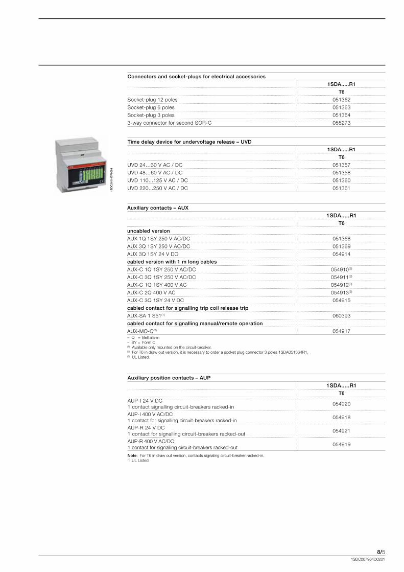
8/51SDC007904D0201
1SD
C21
0147
F00
04
Connectors and socket-plugs for electrical accessories
1SDA.....R1
T6
Socket-plug.12.poles 051362
Socket-plug.6.poles 051363
Socket-plug.3.poles 051364
3-way.connector.for.second.SOR-C 055273
Time delay device for undervoltage release – UVD
1SDA.....R1
T6
UVD.24…30.V.AC./.DC 051357
UVD.48…60.V.AC./.DC 051358
UVD.110...125.V.AC./.DC 051360
UVD.220...250.V.AC./.DC 051361
Auxiliary contacts – AUX
1SDA.....R1T6
uncabled version
AUX.1Q.1SY.250.V.AC/DC 051368
AUX.3Q.1SY.250.V.AC/DC 051369
AUX.3Q.1SY.24.V.DC 054914
cabled version with 1 m long cables
AUX-C.1Q.1SY.250.V.AC/DC 054910(3)
AUX-C.3Q.1SY.250.V.AC/DC 054911(3)
AUX-C.1Q.1SY.400.V.AC 054912(3)
AUX-C.2Q.400.V.AC 054913(3)
AUX-C.3Q.1SY.24.V.DC 054915
cabled contact for signalling trip coil release trip
AUX-SA.1.S51(1) 060393
cabled contact for signalling manual/remote operation
AUX-MO-C(2) 054917–..Q...=. Bell.alarm–..SY.=. Form.C(1). Available.only.mounted.on.the.circuit-breaker.(2).. For.T6.in.draw.out.version,.it.is.necessary.to.order.a.socket.plug.connector.3.poles.1SDA051364R1.(3). UL.Listed.
Auxiliary position contacts – AUP
1SDA.....R1T6
AUP-I.24.V.DC1.contact.signalling.circuit-breakers.racked-in
054920
AUP-I.400.V.AC/DC1.contact.for.signalling.circuit-breakers.racked-in
054918
AUP-R.24.V.DC1.contact.for.signalling.circuit-breakers.racked-out
054921
AUP-R.400.V.AC/DC1.contact.for.signalling.circuit-breakers.racked-out
054919
Note:. For.T6.in.draw.out.version,.contacts.signaling.circuit-breaker.racked-in..(1)..UL.Listed
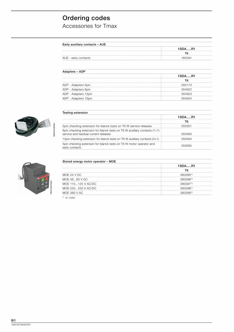
8/61SDC007904D0201
Ordering codesAccessories.for.Tmax
1SD
C21
0125
F00
04
Adapters – ADP
1SDA.....R1T6
ADP.-.Adapters.5pin. 055173
ADP.-.Adapters.6pin. 054922
ADP.-.Adapters.12pin 054923
ADP.-.Adapters.10pin 054924
Testing extension
1SDA.....R1T6
5pin.checking.extension.for.blanck.tests.on.T6.W.service.releases 055351
6pin.checking.extension.for.blanck.tests.on.T6.W.auxiliary.contacts.(1+1).service.and.residual.current.releases
.055063
12pin.checking.extension.for.blanck.tests.on.T6.W.auxiliary.contacts.(3+1) 055064
5pin.checking.extension.for.blanck.tests.on.T6.W.motor.operator.and.early.contacts
055065
1SD
C21
0207
F00
04
Stored energy motor operator – MOE
1SDA.....R1T6
MOE.24.V.DC 060395(1)
MOE.48...60.V.DC 060396(1)
MOE.110...125.V.AC/DC 060397(1)
MOE.220...250.V.AC/DC 060398(1)
MOE.380.V.AC 060399(1)
(1)..UL.Listed
Early auxiliary contacts – AUE
1SDA.....R1T6
AUE.-.early.contacts 060394
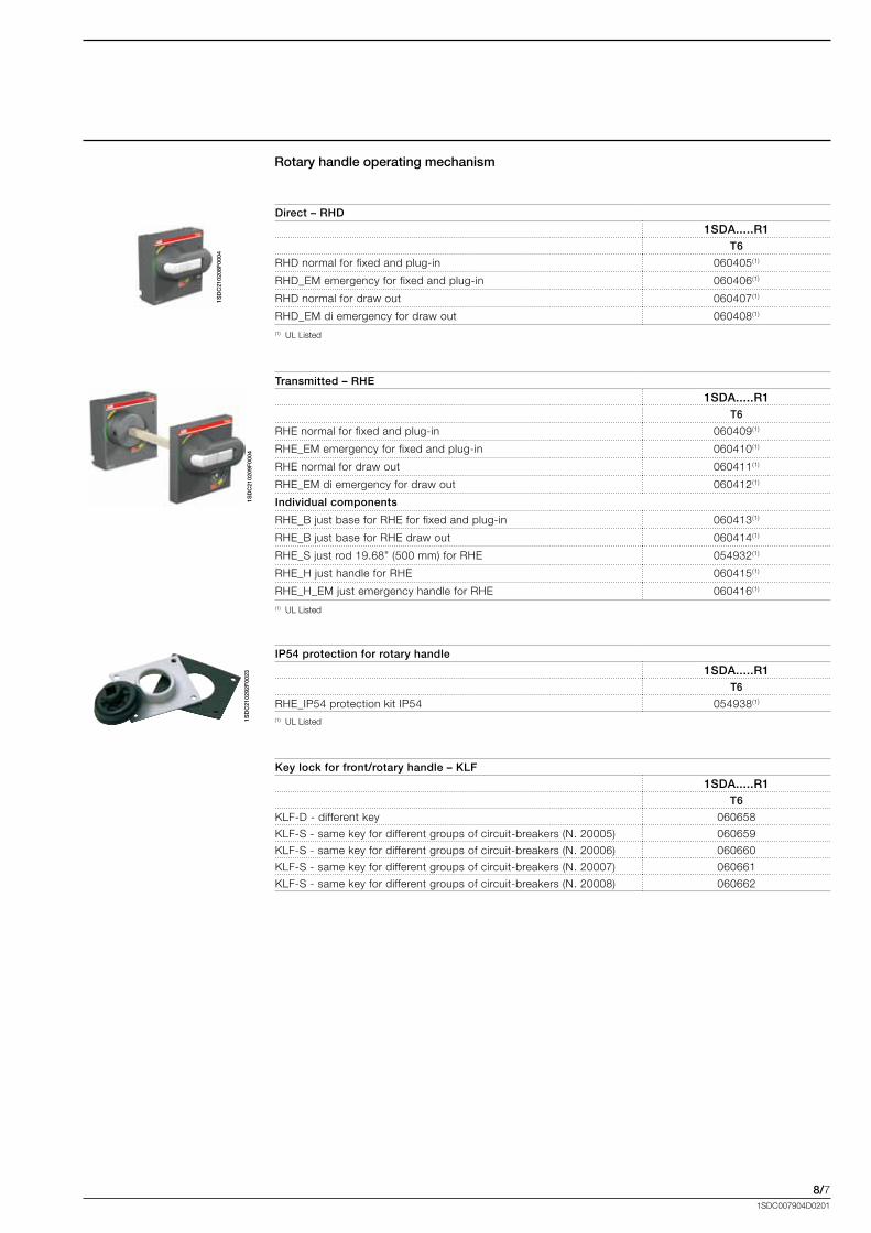
8/71SDC007904D0201
1SD
C21
0208
F00
04
1SD
C21
0209
F00
041S
DC
2102
92F
0023
Direct – RHD
1SDA.....R1T6
RHD.normal.for.fixed.and.plug-in 060405(1)
RHD_EM.emergency.for.fixed.and.plug-in 060406(1)
RHD.normal.for.draw.out 060407(1)
RHD_EM.di.emergency.for.draw.out 060408(1)
(1)..UL.Listed
Rotary handle operating mechanism
Transmitted – RHE
1SDA.....R1T6
RHE.normal.for.fixed.and.plug-in 060409(1)
RHE_EM.emergency.for.fixed.and.plug-in 060410(1)
RHE.normal.for.draw.out 060411(1)
RHE_EM.di.emergency.for.draw.out 060412(1)
Individual components
RHE_B.just.base.for.RHE.for.fixed.and.plug-in 060413(1)
RHE_B.just.base.for.RHE.draw.out 060414(1)
RHE_S.just.rod.19.68”.(500.mm).for.RHE 054932(1)
RHE_H.just.handle.for.RHE 060415(1)
RHE_H_EM.just.emergency.handle.for.RHE 060416(1)
(1)..UL.Listed
IP54 protection for rotary handle
1SDA.....R1T6
RHE_IP54.protection.kit.IP54 054938(1)
(1)..UL.Listed
Key lock for front/rotary handle – KLF
1SDA.....R1T6
KLF-D.-.different.key 060658
KLF-S.-.same.key.for.different.groups.of.circuit-breakers.(N..20005) 060659
KLF-S.-.same.key.for.different.groups.of.circuit-breakers.(N..20006) 060660
KLF-S.-.same.key.for.different.groups.of.circuit-breakers.(N..20007) 060661
KLF-S.-.same.key.for.different.groups.of.circuit-breakers.(N..20008) 060662
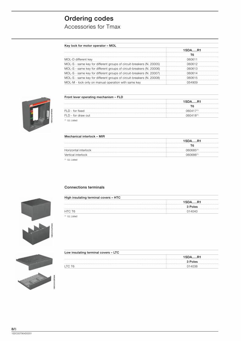
8/81SDC007904D0201
Ordering codesAccessories.for.Tmax
1SD
C21
0210
F00
04
Front lever operating mechanism – FLD
1SDA.....R1T6
FLD.-.for.fixed.. 060417(1)
FLD.-.for.draw.out 060418(1)
(1)..UL.Listed
Mechanical interlock – MIR
1SDA.....R1T6
Horizontal.interlock 060685(1)
Vertical.interlock 060686(1)
(1)..UL.Listed
1SD
C21
0124
F00
04
High insulating terminal covers – HTC
1SDA.....R13 Poles
HTC.T6 014040(1)..UL.Listed
Connections terminals
1SD
C21
0123
F00
04
Low insulating terminal covers – LTC
1SDA.....R13 Poles
LTC.T6 014038
Key lock for motor operator – MOL
1SDA.....R1T6
MOL-D.different.key 060611
MOL-S.-.same.key.for.different.groups.of.circuit-breakers.(N..20005) 060612
MOL-S.-.same.key.for.different.groups.of.circuit-breakers.(N..20006) 060613
MOL-S.-.same.key.for.different.groups.of.circuit-breakers.(N..20007) 060614
MOL-S.-.same.key.for.different.groups.of.circuit-breakers.(N..20008) 060615
MOL-M.-.lock.only.on.manual.operation.with.same.key 054909
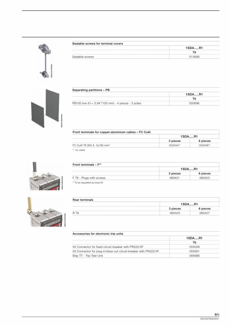
8/91SDC007904D0201
1SD
C21
0127
F00
04
1SD
C21
0203
F00
04
Sealable screws for terminal covers
1SDA.....R1T6
Sealable.screws 013699
Separating partitions – PB
1SDA.....R1T6
PB100.low.(H.=.3.94”/100.mm).-.4.pieces.-.3.poles 050696
1SD
C21
0387
F00
04
Front terminals for copper-aluminium cables – FC CuAl
1SDA.....R13 pieces 6 pieces
FC.CuAl.T6.800.A..3x185.mm2 052044(1). 052048(1).(1)..UL.Listed
Front terminals – F(1)
1SDA.....R13 pieces 6 pieces
F.T6.-.Plugs.with.screws 060421. 060423.(1).To.be.requested.as.loose.kit
1SD
C21
0C50
F00
01
Rear terminals
1SDA.....R13 pieces 6 pieces
R.T6 060425. 060427.
Accessories for electronic trip units
1SDA.....R1T6
X3.Connector.for.fixed.circuit-breaker.with.PR222/VF 055059
X3.Connector.for.plug-in/draw.out.circuit-breaker.with.PR222/VF 055061
Ekip.TT.-.Trip.Test.Unit.. 066988
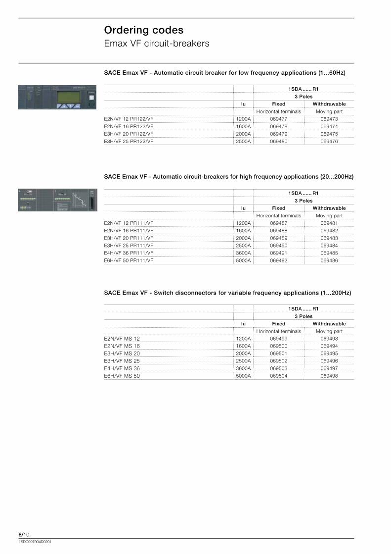
8/101SDC007904D0201
1SDA ...... R1
3 Poles
Iu Fixed Withdrawable
Horizontal.terminals Moving.part
E2N/VF.12.PR122/VF 1200A 069477 069473
E2N/VF.16.PR122/VF 1600A 069478 069474
E3H/VF.20.PR122/VF 2000A 069479 069475
E3H/VF.25.PR122/VF 2500A 069480 069476
Ordering codesEmax.VF.circuit-breakers
SACE Emax VF - Automatic circuit breaker for low frequency applications (1...60Hz)
SACE Emax VF - Automatic circuit-breakers for high frequency applications (20...200Hz)
1SDA ...... R1
3 Poles
Iu Fixed Withdrawable
Horizontal.terminals Moving.part
E2N/VF.12.PR111/VF 1200A 069487 069481
E2N/VF.16.PR111/VF 1600A 069488 069482
E3H/VF.20.PR111/VF 2000A 069489 069483
E3H/VF.25.PR111/VF 2500A 069490 069484
E4H/VF.36.PR111/VF 3600A 069491 069485
E6H/VF.50.PR111/VF 5000A 069492 069486
1SDA ...... R1
3 Poles
Iu Fixed Withdrawable
Horizontal.terminals Moving.part
E2N/VF.MS.12. 1200A 069499 069493
E2N/VF.MS.16 1600A 069500 069494
E3H/VF.MS.20 2000A 069501 069495
E3H/VF.MS.25 2500A 069502 069496
E4H/VF.MS.36. 3600A 069503 069497
E6H/VF.MS.50. 5000A 069504 069498
SACE Emax VF - Switch disconnectors for variable frequency applications (1...200Hz)
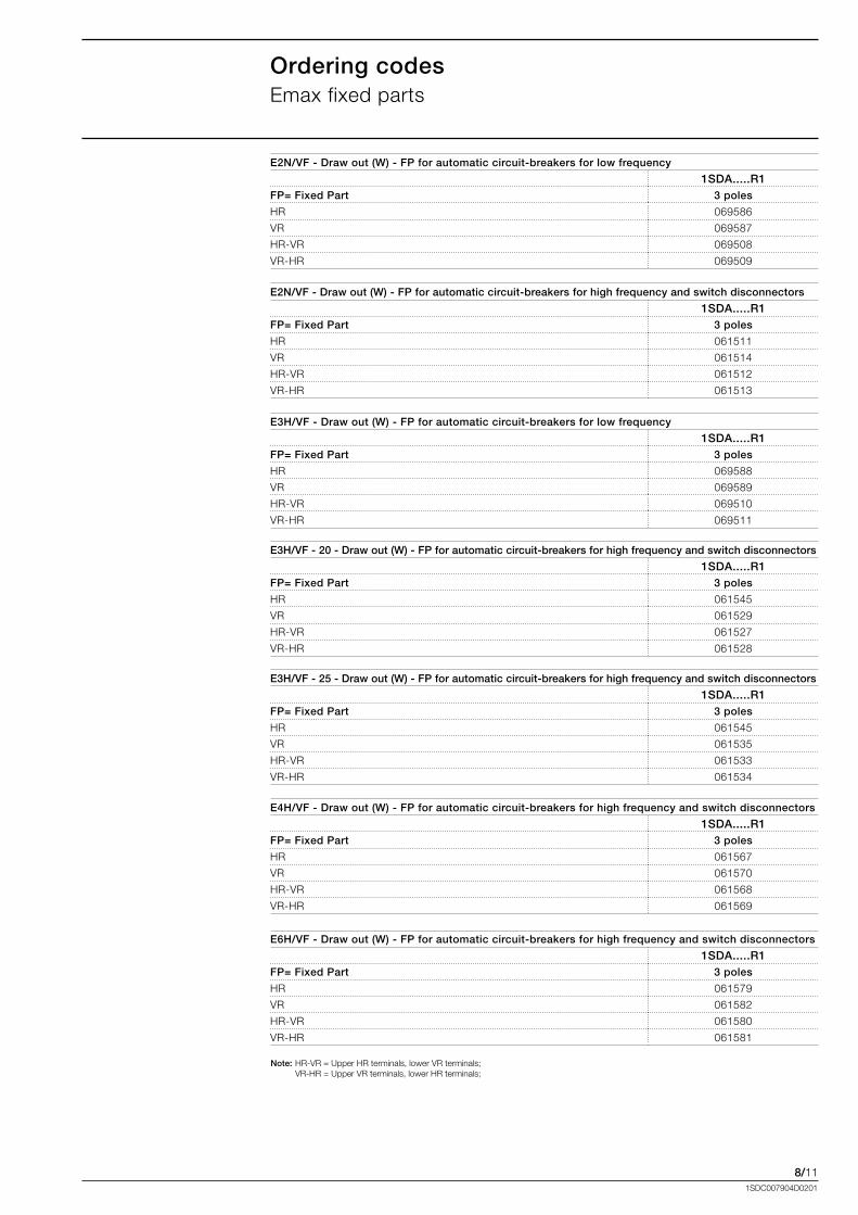
8/111SDC007904D0201
Ordering codesEmax.fixed.parts
E2N/VF - Draw out (W) - FP for automatic circuit-breakers for low frequency
1SDA.....R1FP= Fixed Part 3 poles
HR 069586
VR 069587
HR-VR 069508
VR-HR 069509
E2N/VF - Draw out (W) - FP for automatic circuit-breakers for high frequency and switch disconnectors
1SDA.....R1FP= Fixed Part 3 poles
HR 061511
VR 061514
HR-VR 061512
VR-HR 061513
E3H/VF - Draw out (W) - FP for automatic circuit-breakers for low frequency
1SDA.....R1FP= Fixed Part 3 poles
HR 069588
VR 069589
HR-VR 069510
VR-HR 069511
E3H/VF - 20 - Draw out (W) - FP for automatic circuit-breakers for high frequency and switch disconnectors
1SDA.....R1FP= Fixed Part 3 poles
HR 061545
VR 061529
HR-VR 061527
VR-HR 061528
E3H/VF - 25 - Draw out (W) - FP for automatic circuit-breakers for high frequency and switch disconnectors
1SDA.....R1FP= Fixed Part 3 poles
HR 061545
VR 061535
HR-VR 061533
VR-HR 061534
Note: HR-VR.=.Upper.HR.terminals,.lower.VR.terminals;. VR-HR.=.Upper.VR.terminals,.lower.HR.terminals;
E4H/VF - Draw out (W) - FP for automatic circuit-breakers for high frequency and switch disconnectors
1SDA.....R1FP= Fixed Part 3 poles
HR 061567
VR 061570
HR-VR 061568
VR-HR 061569
E6H/VF - Draw out (W) - FP for automatic circuit-breakers for high frequency and switch disconnectors
1SDA.....R1FP= Fixed Part 3 poles
HR 061579
VR 061582
HR-VR 061580
VR-HR 061581
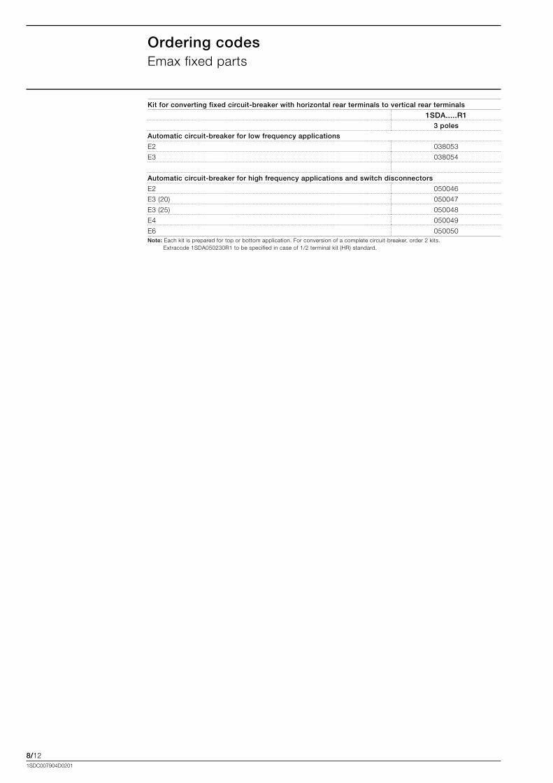
8/121SDC007904D0201
Ordering codesEmax.fixed.parts
Kit for converting fixed circuit-breaker with horizontal rear terminals to vertical rear terminals
1SDA.....R13 poles
Automatic circuit-breaker for low frequency applications
E2 038053
E3 038054
Automatic circuit-breaker for high frequency applications and switch disconnectors
E2 050046
E3.(20) 050047
E3.(25) 050048
E4 050049
E6 050050Note:.Each.kit.is.prepared.for.top.or.bottom.application..For.conversion.of.a.complete.circuit-breaker,.order.2.kits..................................
Extracode.1SDA050230R1.to.be.specified.in.case.of.1/2.terminal.kit.(HR).standard.
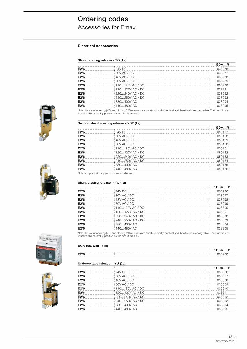
8/131SDC007904D0201
Ordering codesAccessories.for.Emax
Electrical accessories
Shunt opening release - YO (1a)1SDA…R1
E2/6 24V.DC. 038286E2/6 30V.AC./.DC. 038287E2/6 48V.AC./.DC. 038288E2/6 60V.AC./.DC. 038289E2/6 110...120V.AC./.DC 038290E2/6 120…127V.AC./.DC. 038291E2/6 220…240V.AC./.DC. 038292E2/6 240…250V.AC./.DC. 038293E2/6 380…400V.AC. 038294E2/6 440…480V.AC. 038295Note:.the.shunt.opening.(YO).and.closing.(YC).releases.are.constructionally.identical.and.therefore.interchangeable..Their.function.is.linked.to.the.assembly.position.on.the.circuit-breaker.
Second shunt opening release - YO2 (1a)
1SDA…R1E2/6 24V.DC 050157E2/6 30V.AC./.DC. 050158E2/6 48V.AC./.DC. 050159E2/6 60V.AC./.DC. 050160E2/6 110...120V.AC./.DC. 050161E2/6 120…127V.AC./.DC. 050162E2/6 220…240V.AC./.DC. 050163E2/6 240…250V.AC./.DC. 050164E2/6 380…400V.AC. 050165E2/6 440…480V.AC 050166Note:.supplied.with.support.for.special.releases.
Shunt closing release - YC (1a) 1SDA…R1
E2/6 24V.DC. 038296E2/6 30V.AC./.DC. 038297E2/6 48V.AC./.DC. 038298E2/6 60V.AC./.DC. 038299E2/6 110...120V.AC./.DC. 038300E2/6 120…127V.AC./.DC. 038301E2/6 220…240V.AC./.DC. 038302E2/6 240…250V.AC./.DC. 038303E2/6 380…400V.AC. 038304E2/6 440…480V.AC. 038305Note:.the.shunt.opening.(YO).and.closing.(YC).releases.are.constructionally.identical.and.therefore.interchangeable..Their.function.is.linked.to.the.assembly.position.on.the.circuit-breaker.
SOR Test Unit - (1b) 1SDA…R1
E2/6 . 050228
Undervoltage release - YU (2a)1SDA…R1
E2/6 24V.DC 038306E2/6 30V.AC./.DC. 038307E2/6 48V.AC./.DC. 038308E2/6 60V.AC./.DC. 038309E2/6 110...120V.AC./.DC. 038310E2/6 120…127V.AC./.DC. 038311E2/6 220…240V.AC./.DC. 038312E2/6 240…250V.AC./.DC. 038313E2/6 380…400V.AC. 038314E2/6 440…480V.AC. 038315
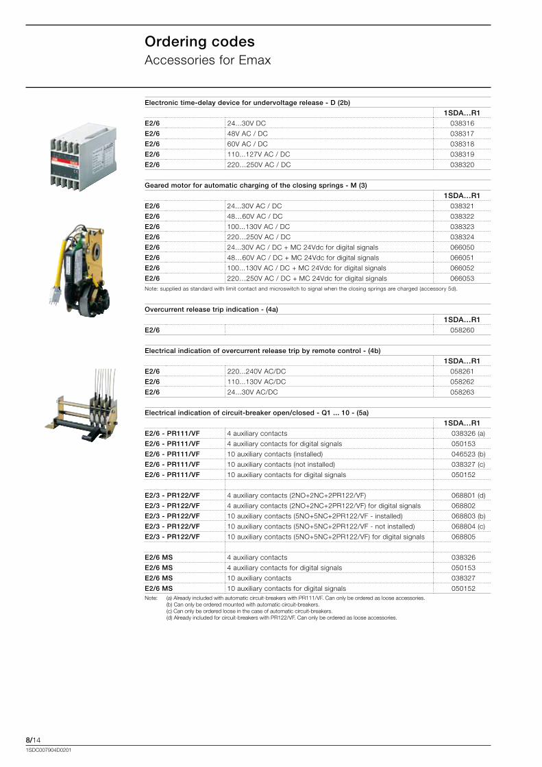
8/141SDC007904D0201
Ordering codesAccessories.for.Emax
Electronic time-delay device for undervoltage release - D (2b)
1SDA…R1E2/6 24...30V.DC.. 038316
E2/6 48V.AC./.DC. 038317
E2/6 60V.AC./.DC. 038318
E2/6 110...127V.AC./.DC. 038319
E2/6 220…250V.AC./.DC. 038320
Geared motor for automatic charging of the closing springs - M (3)
1SDA…R1E2/6 .24...30V.AC./.DC 038321
E2/6 .48…60V.AC./.DC 038322
E2/6 .100...130V.AC./.DC 038323
E2/6 .220…250V.AC./.DC 038324
E2/6 .24...30V.AC./.DC.+.MC.24Vdc.for.digital.signals 066050
E2/6 .48…60V.AC./.DC.+.MC.24Vdc.for.digital.signals 066051
E2/6 .100...130V.AC./.DC.+.MC.24Vdc.for.digital.signals 066052
E2/6 .220…250V.AC./.DC.+.MC.24Vdc.for.digital.signals 066053Note:.supplied.as.standard.with.limit.contact.and.microswitch.to.signal.when.the.closing.springs.are.charged.(accessory.5d).
Overcurrent release trip indication - (4a)
1SDA…R1E2/6 058260
Electrical indication of overcurrent release trip by remote control - (4b)
1SDA…R1E2/6 220...240V.AC/DC 058261
E2/6 110...130V.AC/DC 058262
E2/6 24...30V.AC/DC 058263
Electrical indication of circuit-breaker open/closed - Q1 ... 10 - (5a)
1SDA…R1E2/6 - PR111/VF .4.auxiliary.contacts 038326.(a)
E2/6 - PR111/VF .4.auxiliary.contacts.for.digital.signals 050153
E2/6 - PR111/VF .10.auxiliary.contacts.(installed) 046523.(b)
E2/6 - PR111/VF .10.auxiliary.contacts.(not.installed) 038327.(c)
E2/6 - PR111/VF .10.auxiliary.contacts.for.digital.signals 050152
E2/3 - PR122/VF .4.auxiliary.contacts.(2NO+2NC+2PR122/VF) 068801.(d)
E2/3 - PR122/VF .4.auxiliary.contacts.(2NO+2NC+2PR122/VF).for.digital.signals 068802
E2/3 - PR122/VF .10.auxiliary.contacts.(5NO+5NC+2PR122/VF.-.installed) 068803.(b)
E2/3 - PR122/VF .10.auxiliary.contacts.(5NO+5NC+2PR122/VF.-.not.installed) 068804.(c)
E2/3 - PR122/VF .10.auxiliary.contacts.(5NO+5NC+2PR122/VF).for.digital.signals 068805
E2/6 MS .4.auxiliary.contacts 038326
E2/6 MS .4.auxiliary.contacts.for.digital.signals 050153
E2/6 MS .10.auxiliary.contacts 038327
E2/6 MS .10.auxiliary.contacts.for.digital.signals 050152Note:
.
(a).Already.included.with.automatic.circuit-breakers.with.PR111/VF..Can.only.be.ordered.as.loose.accessories..............................(b).Can.only.be.ordered.mounted.with.automatic.circuit-breakers........................................................................................................................(c).Can.only.be.ordered.loose.in.the.case.of.automatic.circuit-breakers.(d).Already.included.for.circuit-breakers.with.PR122/VF..Can.only.be.ordered.as.loose.accessories.
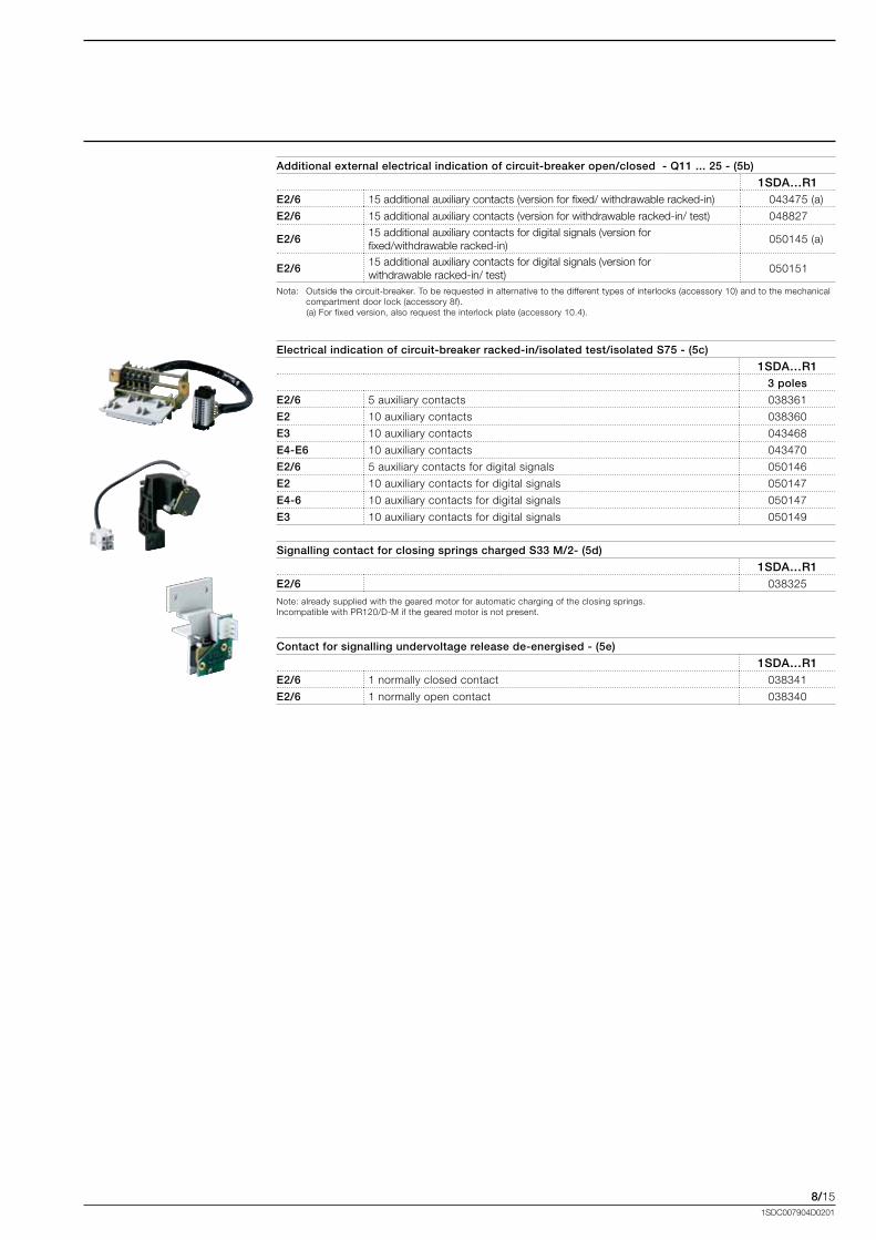
8/151SDC007904D0201
Additional external electrical indication of circuit-breaker open/closed - Q11 ... 25 - (5b)
1SDA…R1E2/6 15.additional.auxiliary.contacts.(version.for.fixed/.withdrawable.racked-in) 043475.(a)
E2/6 15.additional.auxiliary.contacts.(version.for.withdrawable.racked-in/.test) 048827
E2/6 15.additional.auxiliary.contacts.for.digital.signals.(version.for.fixed/withdrawable.racked-in)..
050145.(a)
E2/6 15.additional.auxiliary.contacts.for.digital.signals.(version.for.withdrawable.racked-in/.test)
050151
Nota:.. Outside.the.circuit-breaker..To.be.requested.in.alternative.to.the.different.types.of.interlocks.(accessory.10).and.to.the.mechanical.compartment.door.lock.(accessory.8f)..
...........(a).For.fixed.version,.also.request.the.interlock.plate.(accessory.10.4).
Electrical indication of circuit-breaker racked-in/isolated test/isolated S75 - (5c)
1SDA…R13 poles
E2/6 5.auxiliary.contacts. 038361
E2 10.auxiliary.contacts. 038360
E3 10.auxiliary.contacts. 043468
E4-E6 10.auxiliary.contacts. 043470
E2/6 5.auxiliary.contacts.for.digital.signals. 050146
E2 10.auxiliary.contacts.for.digital.signals 050147
E4-6 10.auxiliary.contacts.for.digital.signals 050147
E3 10.auxiliary.contacts.for.digital.signals 050149
Signalling contact for closing springs charged S33 M/2- (5d)
1SDA…R1E2/6 038325
Note:.already.supplied.with.the.geared.motor.for.automatic.charging.of.the.closing.springs..Incompatible.with.PR120/D-M.if.the.geared.motor.is.not.present.
Contact for signalling undervoltage release de-energised - (5e)
1SDA…R1E2/6 1.normally.closed.contact. 038341
E2/6 1.normally.open.contact 038340
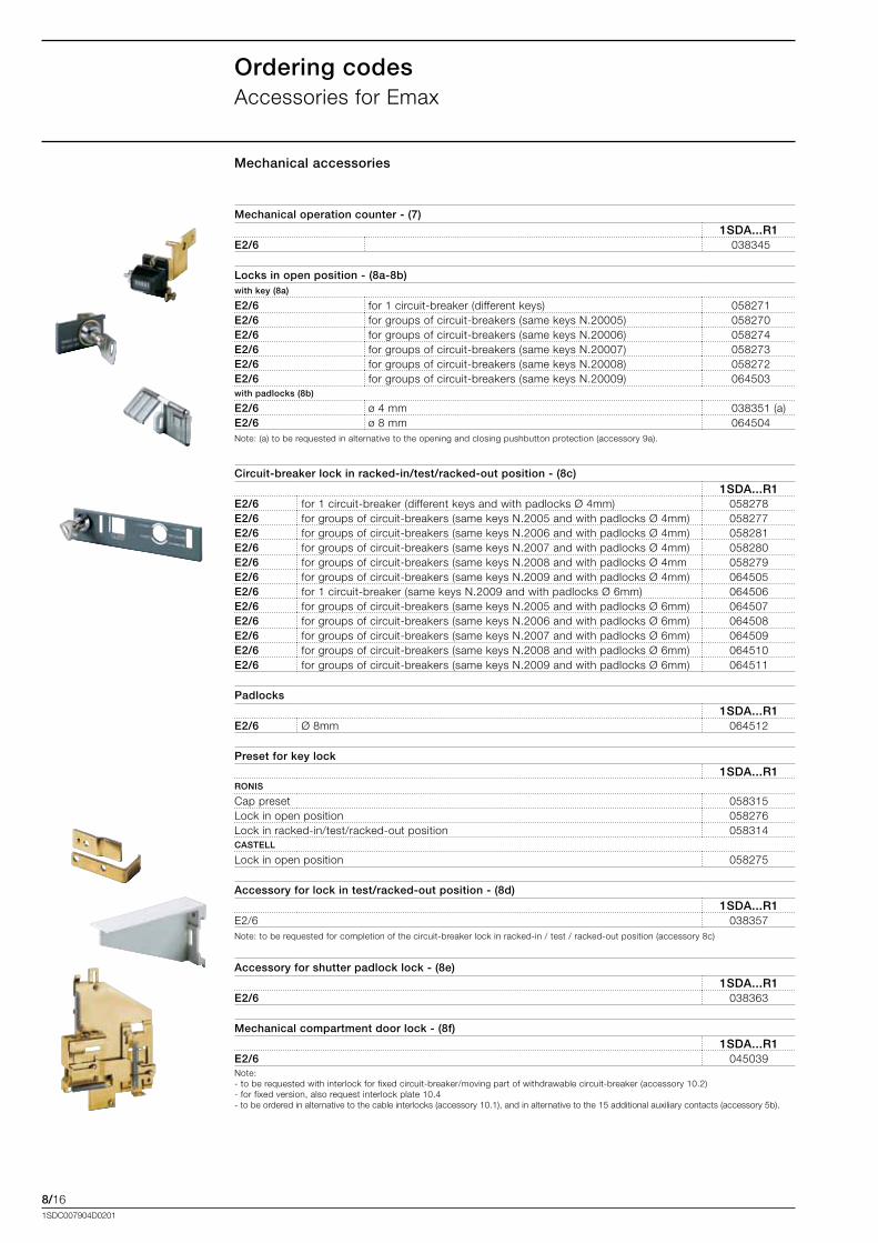
8/161SDC007904D0201
Ordering codesAccessories.for.Emax
Mechanical operation counter - (7) 1SDA...R1
E2/6 038345
Locks in open position - (8a-8b)with key (8a)
E2/6 for.1.circuit-breaker.(different.keys). 058271E2/6 for.groups.of.circuit-breakers.(same.keys.N.20005) 058270E2/6 for.groups.of.circuit-breakers.(same.keys.N.20006).. 058274E2/6 for.groups.of.circuit-breakers.(same.keys.N.20007) 058273E2/6 for.groups.of.circuit-breakers.(same.keys.N.20008). 058272E2/6 for.groups.of.circuit-breakers.(same.keys.N.20009). 064503with padlocks (8b)
E2/6 ø.4.mm 038351.(a)E2/6 ø.8.mm 064504Note:.(a).to.be.requested.in.alternative.to.the.opening.and.closing.pushbutton.protection.(accessory.9a).
Mechanical accessories
Circuit-breaker lock in racked-in/test/racked-out position - (8c)1SDA...R1
E2/6 for.1.circuit-breaker.(different.keys.and.with.padlocks.Ø.4mm) 058278E2/6 for.groups.of.circuit-breakers.(same.keys.N.2005.and.with.padlocks.Ø.4mm) 058277E2/6 for.groups.of.circuit-breakers.(same.keys.N.2006.and.with.padlocks.Ø.4mm) 058281E2/6 for.groups.of.circuit-breakers.(same.keys.N.2007.and.with.padlocks.Ø.4mm) 058280E2/6 for.groups.of.circuit-breakers.(same.keys.N.2008.and.with.padlocks.Ø.4mm 058279E2/6 for.groups.of.circuit-breakers.(same.keys.N.2009.and.with.padlocks.Ø.4mm) 064505E2/6 for.1.circuit-breaker.(same.keys.N.2009.and.with.padlocks.Ø.6mm) 064506E2/6 for.groups.of.circuit-breakers.(same.keys.N.2005.and.with.padlocks.Ø.6mm) 064507E2/6 for.groups.of.circuit-breakers.(same.keys.N.2006.and.with.padlocks.Ø.6mm) 064508E2/6 for.groups.of.circuit-breakers.(same.keys.N.2007.and.with.padlocks.Ø.6mm) 064509E2/6 for.groups.of.circuit-breakers.(same.keys.N.2008.and.with.padlocks.Ø.6mm) 064510E2/6 for.groups.of.circuit-breakers.(same.keys.N.2009.and.with.padlocks.Ø.6mm) 064511
Padlocks 1SDA...R1
E2/6 Ø.8mm 064512
Preset for key lock1SDA...R1
RONIS
Cap.preset. 058315Lock.in.open.position. 058276Lock.in.racked-in/test/racked-out.position 058314CASTELL
Lock.in.open.position. 058275
Accessory for lock in test/racked-out position - (8d)1SDA...R1
E2/6 038357Note:.to.be.requested.for.completion.of.the.circuit-breaker.lock.in.racked-in./.test./.racked-out.position.(accessory.8c)
Accessory for shutter padlock lock - (8e)1SDA...R1
E2/6 038363
Mechanical compartment door lock - (8f)1SDA...R1
E2/6 045039Note:.-.to.be.requested.with.interlock.for.fixed.circuit-breaker/moving.part.of.withdrawable.circuit-breaker.(accessory.10.2)-.for.fixed.version,.also.request.interlock.plate.10.4-.to.be.ordered.in.alternative.to.the.cable.interlocks.(accessory.10.1),.and.in.alternative.to.the.15.additional.auxiliary.contacts.(accessory.5b).
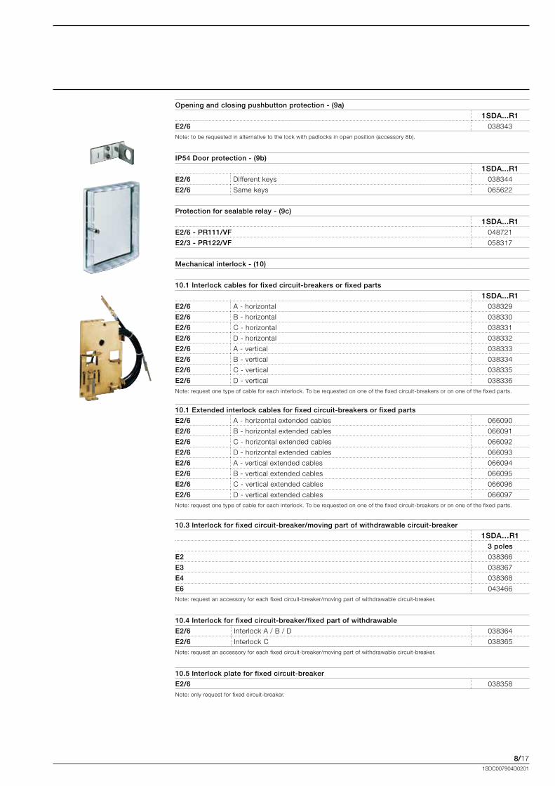
8/171SDC007904D0201
Opening and closing pushbutton protection - (9a)
1SDA...R1E2/6 038343Note:.to.be.requested.in.alternative.to.the.lock.with.padlocks.in.open.position.(accessory.8b).
IP54 Door protection - (9b)
1SDA...R1E2/6 Different.keys 038344
E2/6 Same.keys 065622
Protection for sealable relay - (9c)
1SDA...R1E2/6 - PR111/VF 048721
E2/3 - PR122/VF 058317
Mechanical interlock - (10)
.
10.1 Interlock cables for fixed circuit-breakers or fixed parts
1SDA...R1E2/6 A.-.horizontal. 038329
E2/6 B.-.horizontal. 038330
E2/6 C.-.horizontal. 038331
E2/6 D.-.horizontal. 038332
E2/6 A.-.vertical 038333
E2/6 B.-.vertical 038334
E2/6 C.-.vertical 038335
E2/6 D.-.vertical. 038336Note:.request.one.type.of.cable.for.each.interlock..To.be.requested.on.one.of.the.fixed.circuit-breakers.or.on.one.of.the.fixed.parts.
10.3 Interlock for fixed circuit-breaker/moving part of withdrawable circuit-breaker
1SDA…R13 poles
E2. 038366
E3. 038367
E4 038368
E6 043466Note:.request.an.accessory.for.each.fixed.circuit-breaker/moving.part.of.withdrawable.circuit-breaker.
10.4 Interlock for fixed circuit-breaker/fixed part of withdrawable
E2/6 Interlock.A./.B./.D. 038364
E2/6 Interlock.C. 038365Note:.request.an.accessory.for.each.fixed.circuit-breaker/moving.part.of.withdrawable.circuit-breaker.
10.5 Interlock plate for fixed circuit-breaker
E2/6 038358Note:.only.request.for.fixed.circuit-breaker.
10.1 Extended interlock cables for fixed circuit-breakers or fixed parts
E2/6 A.-.horizontal.extended.cables. 066090
E2/6 B.-.horizontal.extended.cables 066091
E2/6 C.-.horizontal.extended.cables 066092
E2/6 D.-.horizontal.extended.cables 066093
E2/6 A.-.vertical.extended.cables 066094
E2/6 B.-.vertical.extended.cables 066095
E2/6 C.-.vertical.extended.cables 066096
E2/6 D.-.vertical.extended.cables 066097Note:.request.one.type.of.cable.for.each.interlock..To.be.requested.on.one.of.the.fixed.circuit-breakers.or.on.one.of.the.fixed.parts.
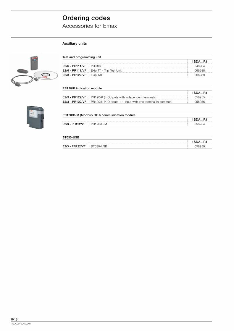
8/181SDC007904D0201
Ordering codesAccessories.for.Emax
Test and programming unit
1SDA...R1E2/6 - PR111/VF PR010/T 048964
E2/6 - PR111/VF Ekip.TT.-.Trip.Test.Unit 066988
E2/3 - PR122/VF Ekip.T&P 066989
PR120/K indication module
1SDA...R1E2/3 - PR122/VF PR120/K.(4.Outputs.with.independent.terminals). 058255
E2/3 - PR122/VF PR120/K.(4.Outputs.+.1.Input.with.one.terminal.in.common). 058256
PR120/D-M (Modbus RTU) communication module
1SDA...R1E2/3 - PR122/VF PR120/D-M 058254
BT030-USB
1SDA...R1E2/3 - PR122/VF BT030-USB 058259
Auxiliary units


Contact us
ABB SACEA division of ABB S.p.A.L.V. BreakersVia Baioni, 3524123 BergamoPhone: +39 035 395.111Fax: +39 035 395.306-433
www.abb.com
1SD
C00
7904
D02
01 -
201
1.01
(Pre
limin
ary)The data and illustrations are not binding. We reserve
the right to modify the contents of this document on the basis of technical development of the products, without prior notice.
Copyright 2011 ABB.All rights reserved.