abi-199-62a wheel & brake kit - airframes alaska 199-62a ica rev b.pdf · assembly, page 19)....
TRANSCRIPT

ABI, LLC| 20130 BIRCHWOOD SPUR RD | PO Box 670989 | Chugiak, AK 99567 | USA
INSTALLATION INSTRUCTIONS
And
INSTRUCTIONS FOR CONTINUED AIRWORTHINESS
For the installation of
ABI-199-62A WHEEL & BRAKE KIT
For
CESSNA AIRCRAFT SERIES 180, 185, 206
Doc No.: ABI-199-62A-4 – REV B 04/21/2017

ABI-199-62A WHEEL AND BRAKE KIT
INSTALLATION AND ICA MANUAL
Installation and ICA for ABI-199-62A Wheel & Brake Kit – Revision B Page 2 of 21
TABLE OF CONTENTS
1.0 INTRODUCTION ..................................................................................... 4
1.1 PURPOSE .......................................................................................... 4
2.0 KIT COMPONENTS .................................................................................. 4
3.0 APPLICABILITY ...................................................................................... 4
4.0 EQUIPMENT DESCRIPTION ......................................................................... 5
4.1 WHEEL ASSEMBLY DESCRIPTION ............................................................... 5
4.2 BRAKE ASSEMBLY DESCRIPTION ............................................................... 5
5.0 INSTALLATION INSTRUCTIONS .................................................................... 7
5.1 REMOVE EXISTING EQUIPMENT ................................................................ 7
5.2 ASSEMBLE ABI WHEELS ......................................................................... 7
5.3 INSTALL ABI WHEELS ............................................................................ 9
5.4 INSTALL ABI BRAKES .......................................................................... 10
5.5 BLEED BRAKES ................................................................................. 10
5.6 BRAKE PAD CONDITIONING ................................................................... 10
5.7 WEIGHT AND BALANCE COMPUTATIONS .................................................... 10
6.0 INSTRUCTIONS FOR CONTINUED AIRWORTHINESS ........................................... 12
6.1 INSPECTION BEFORE FLIGHT ................................................................. 12
6.2 REMOVE BRAKE ASSEMBLY ................................................................... 12
6.3 REMOVE WHEEL ASSEMBLY ................................................................... 12
6.4 WHEEL DISASSEMBLY .......................................................................... 13
6.5 WHEEL INSPECTION AND REPAIR ............................................................ 13
6.6 REINSTALLING BEARING RACES .............................................................. 14
6.7 BRAKE DISC INSPECTION AND REPAIR ....................................................... 15
6.8 BRAKE CLEANING, INSPECTION & REPAIR .................................................. 15
6.9 ASSEMBLE ABI WHEELS ....................................................................... 15
6.10 INSTALL WHEELS .............................................................................. 15
6.11 INSTALL ABI BRAKES .......................................................................... 15
6.12 BLEED BRAKES ................................................................................. 15
6.13 BRAKE PAD CONDITIONING ................................................................... 15
7.0 BRAKE SYSTEM TROUBLESHOOTING GUIDE ................................................... 16
AIRWORTHINESS LIMITATIONS .......................................................................... 18
FIGURE 1: ABI-199-62A BRAKE & WHEEL KIT ......................................................... 19
FIGURE 2: ABI-40-75T WHEEL ASSEMBLY ............................................................. 20
FIGURE 3: ABI-30-52N BRAKE ASSEMBLY .............................................................. 21

ABI-199-62A WHEEL AND BRAKE KIT
INSTALLATION AND ICA MANUAL
Installation and ICA for ABI-199-62A Wheel & Brake Kit – Revision B Page 3 of 21
LIST OF REVISIONS
REVISION DATE PAGE DESCRIPTION
IR 08/15/2013 ALL Initial Release A 08/22/2013 18 Add Airworthiness Limitations B 04/21/2017 4 Remove Cessna A185E and A185F

ABI-199-62A WHEEL AND BRAKE KIT
INSTALLATION AND ICA MANUAL
Installation and ICA for ABI-199-62A Wheel & Brake Kit – Revision B Page 4 of 21
1.0 INTRODUCTION
This manual addresses the installation and instructions for continued airworthiness for the ABI-199-62A Wheel and Brake Kit. It is published for the guidance of qualified maintenance personnel responsible for the installation and/or continued airworthiness of an ABI, LLC (ABI) wheel and brake kit for Cessna Series 180, 185, and 206 aircraft.
1.1 PURPOSE
This manual provides the necessary procedures to accomplish the installation and continued airworthiness of an ABI Wheel & Brake kit. The manual should be passed on to the owner or retained by the maintenance facility for future reference
2.0 KIT COMPONENTS
The ABI Wheel & Brake Kit contains all the components required to replace the existing wheels and brakes for one aircraft. The ABI-199-62A kit contains the following components (See Figure 1: ABI-199-62A Brake & Wheel Kit, page 18):
ABI-199-62A Wheel & Brake Kit Parts List
Part Number Description Quantity Reference
ABI-40-75T Wheel Assembly 2 Fig 2
ABI-30-52N Brake Assembly 2 Fig 3
ABI-199-62A
ICA Installation and ICA Manual 1
3.0 APPLICABILITY
The ABI-199-62A kit is applicable to the following aircraft:
Make Models
Cessna 180, 180A, 180B, 180C, 180D, 180E, 180F, 180G, 180H, 180J, 180K
Cessna 185, 185A, 185B, 185C, 185D, 185E
Cessna 206, P206, U206, U206F, U206G, TU206E, TU206F, TU206G

ABI-199-62A WHEEL AND BRAKE KIT
INSTALLATION AND ICA MANUAL
Installation and ICA for ABI-199-62A Wheel & Brake Kit – Revision B Page 5 of 21
4.0 EQUIPMENT DESCRIPTION
4.1 WHEEL ASSEMBLY DESCRIPTION
4.1.1 Wheel Assembly Overview
The wheel is cast aluminum and conforms to all tire and rim association standards for a 6.00-6 divided type wheel. It is a tube-type design only. The ABI-40-75T is a heavy duty 1.5” axle wheel with six AN5-36A tie bolts holding the wheel halves together. The wheel incorporates inboard and outboard halves which are fastened together with bolts, washers, and nuts. The brake disc is attached to the wheel by the bolts. The wheel rotates on two tapered roller bearings, which seat in bearing cups in the wheel half hubs. Felt grease seals provide protection and lubricant retention for the bearing.
All aircraft wheels are designed and qualification tested in accordance with TSO C26a for a particular tire type and size matching the aircraft requirements. Operating a wheel assembly with unapproved tires, improper inflation pressures or subjected to loads in excess of its design is a violation of the wheel certification basis and is prohibited.
4.1.2 Wheel Assembly Detail (See Figure 2: ABI-40-75T Wheel Assembly, page 19)
The wheel is of the divided type, incorporating inner wheel half (1) and outer wheel half (2), which are fastened together with tie bolts (3), washers (4), and nuts (5). The brake disc (6) is attached to the wheel by the tie bolts. The wheels are tube type. The wheel rotates on two tapered roller bearings (8) which seat in bearing cups (7) in the hubs. Grease seals (11 & 14) provide protection and lubricant retention for the bearings. All new product shipped will have the bearings packed with the appropriate grease. Felt grease seals are shipped dry. Remove the felt seals and lightly coat all surfaces of the felt with the wheel bearing grease and reinstall prior to wheel use. Hubcaps, when used, are secured to the outboard wheel half by three attachment screws (not shown). CAUTION: THE FELT GREASE SEALS ARE SHIPPED DRY. THEY MUST BE LUBRICATED TO PROVIDE PROTECTION AND LUBRICANT RETENTION FOR THE BEARINGS. IF THEY ARE NOT PROPERLY LUBRICATED THEN MOISTURE CAN SOAK PAST THE FELTS AND CONTACT THE BEARINGS WHICH CAN LEAD TO BEARING FAILURE.
4.2 BRAKE ASSEMBLY DESCRIPTION
4.2.1 Brake Assembly Overview
The brake is a single caliper, 2 piston external disc design, with organic lining. It is suitable for use with brake fluid conforming to MIL-H-5606.

ABI-199-62A WHEEL AND BRAKE KIT
INSTALLATION AND ICA MANUAL
Installation and ICA for ABI-199-62A Wheel & Brake Kit – Revision B Page 6 of 21
The cylinder contains the brake fluid which operates the pistons and pressure plate. Back plates are secured to the cylinder with bolts and washers on the opposite side of the brake disc. The back plates and pressure plate each hold brake linings. Two anchor bolts, attached to the cylinder with nuts and washers, slide or float in anchor plate bushings. The anchor plate is mounted to the landing gear axle. The caliper (cylinder assembly) is the assembly which includes the cylinder, pistons, back and pressure plates, linings and other related components.
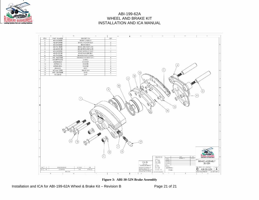
4.2.2 Brake Assembly Detail (See Figure 3: ABI-30-52N Brake Assembly, page 20)
The cylinder (1) is a cast aluminum housing. The pistons (3) are contained by the cylinder and form a pressure vessel for the brake fluid. Two anchor bolts (2) are attached to the cylinder (1) with nuts (11) and washers (12). The anchor bolts slide or float through bushings in the anchor plate (4) and pressure plate (5), which allows the cylinder and pressure plate to slide into alignment with the disc. The backing plate (6) is secured to the cylinder with bolts (14) and washers (13) on the opposite side of the brake disc. The backing plate and pressure plate each hold brake pads (15). The anchor plate is mounted to the landing gear axle. The caliper (cylinder assembly) is the assembly which includes the cylinder, pistons, backing and pressure plates, linings, and other related components.

ABI-199-62A WHEEL AND BRAKE KIT
INSTALLATION AND ICA MANUAL
Installation and ICA for ABI-199-62A Wheel & Brake Kit – Revision B Page 7 of 21
5.0 INSTALLATION INSTRUCTIONS
5.1 REMOVE EXISTING EQUIPMENT
5.1.1 Properly raise the aircraft off the ground following the airframe manufacturer’s instructions.
5.1.2 Fully deflate tire.
5.1.3 Remove backing plate bolts and backing plates from behind brake disc.
5.1.4 Remove and retain axle nut.
5.1.5 Remove existing main landing gear wheels.
5.1.6 Disconnect lower hydraulic line (existing flexible inlet hose or rigid inlet line) at brake inlet fitting and cap line.
5.1.7 Remove and retain inlet fitting from existing brake assemblies.
5.1.8 Remove existing brake assemblies and anchor plates from axle.
5.1.9 Disassemble wheel halves and remove tires and tubes from wheels.
5.2 ASSEMBLE ABI WHEELS
Assemble ABI-40-75D wheels and brake discs with tires (see Figure 2: ABI-40-75T Wheel Assembly, page 19).
5.2.1 Ensure that the wheel is clean and dry. Particular attention should be paid to the bead area to ensure that it is clean, dry and free of grease or other contamination.
5.2.2 Insert the inner tube into the tire. Align the red dot on the tire (its light point) with the white or yellow dot on the tube (its heaviest point). If the tube does not have a white dot, align the red dot on the tire with the valve stem of the tube. In order to allow the tube to move freely within the tire, it is recommended that you lightly coat the tube and inner part of the tire with talc powder.
5.2.3 Inflate the inner tube to approximately 10 psi, allowing it to take the shape of the tire. Deflate to the point that it just retains its shape.
5.2.4 Place the tire and tube onto the outer wheel half carefully inserting the valve stem through the hole in the wheel half.

ABI-199-62A WHEEL AND BRAKE KIT
INSTALLATION AND ICA MANUAL
Installation and ICA for ABI-199-62A Wheel & Brake Kit – Revision B Page 8 of 21
5.2.5 Insert the inner wheel half into the tire with the tie bolt holes aligned and using care not to pinch the inner tube.
5.2.6 Insert the three tie bolts, with washers under the heads, through the wheel.
5.2.7 Rotate the wheel from the working surface in order to be able to attach the nuts to the tie bolts. Hand tighten a nut with washer on each of the tie bolts. Care should be taken to ensure that the wheel halves are in contact with each other and not pinching the inner tube.
5.2.8 Tighten the tie bolt nuts to a dry torque value of 150 inch-pounds.
NOTE: REPACKING BEARINGS PER STEPS 5.2.9 THRU 5.2.10 IS NOT REQUIRED FOR NEW ABI WHEELS DURING FIRST INSTALLATION. WHEEL BEARINGS ARE PACKED AND ASSEMBLED AT THE FACTORY.
5.2.9 Repack the bearings using MIL-G-81322 grease such as Aeroshell 22, Mobil 28, or equivalent.
5.2.10 With the wheel on a flat working surface, insert a wheel bearing. Lightly coat the bearing race with bearing grease before installing the bearing.
5.2.11 Install the washers, felt grease seal and retention snap ring. A light coat of light weight oil on the felt grease seal is recommended.
CAUTION: THE FELT GREASE SEALS ARE SHIPPED DRY. THEY MUST BE LUBRICATED TO PROVIDE PROTECTION AND LUBRICANT RETENTION FOR THE BEARINGS. IF THEY ARE NOT PROPERLY LUBRICATED THEN MOISTURE CAN SOAK PAST THE FELTS AND CONTACT THE BEARINGS WHICH CAN LEAD TO BEARING FAILURE.
5.2.12 Turn the wheel over and repeat steps 5.2.10. and 5.2.11.
5.2.13 Place the wheel in a protective enclosure and inflate to 25 psi. Deflate the tire by depressing the valve stem plunger and re-inflate to the pressure recommended by the aircraft manufacturer.

ABI-199-62A WHEEL AND BRAKE KIT
INSTALLATION AND ICA MANUAL
Installation and ICA for ABI-199-62A Wheel & Brake Kit – Revision B Page 9 of 21
5.3 INSTALL ABI WHEELS
5.3.1 Inspect the axle to ensure that it is clean, dry and in serviceable condition.
5.3.2 Install the wheel onto the axle.
5.3.3 Install the axle nut and hand tighten ensuring that that the wheel bearings are fully seated on the axle.
5.3.4 Install axle nut. Axle nut torqueing procedures vary considerably. The following procedure is based on the best available service information. Torque axle nut using value specified in aircraft manual or the following:
1. Rotate the wheel/tire while tightening axle nut to 150-200 in-lbs. to seat the bearing.
2. Back off axle nut to zero torque.
3. Tighten axle nut 30-40 in-lbs. while rotating wheel/tire.
NOTE: Wheel must rotate freely without perceptible play.
5.3.5 Align the axle nut to the nearest hole in the nut with the cotter pin slot in the axle. If you need to move the nut for alignment, first try to tighten it. If the wheel still moves with little or no resistance, use that alignment. If there is increased resistance to rotation, loosen the nut to the next hole.
5.3.6 Install a new cotter pin. One end of the cotter pin should fold out and bend over the end of the axle to its center. The other end should be bent back toward the wheel and shortened if necessary to avoid contact with the wheel. Extreme care must be taken to ensure that the cotter pin does not interfere with the valve stem or other parts of the wheel when the wheel is rotated.
5.3.7 Reinstall the wheel hub cap if so equipped.
5.3.8 Rotate the wheel to ensure that it is secure and rotates freely.
5.3.9 Lower the aircraft to the ground following aircraft manufacturer’s instructions.

ABI-199-62A WHEEL AND BRAKE KIT
INSTALLATION AND ICA MANUAL
Installation and ICA for ABI-199-62A Wheel & Brake Kit – Revision B Page 10 of 21
5.4 INSTALL ABI BRAKES
5.4.1 Install ABI-75-13600 anchor plate on axle using hardware specified in airframe manufacturer’s instructions. Use ABI-145-01000 anchor plate bushings (4 ea.), as required, on anchor plate/axle hole locations (see Figure 3: ABI-30-52N Brake Assembly, page 20).
5.4.2 Remove backing plates from brake assembly. Slide brake assembly anchor bolts into anchor plate bushings. Reassemble backing plates behind brake disc and dry torque bolts to 90 in-lbs.
5.4.3 Install existing brake inlet fittings to ABI brake cylinders.
5.4.4 Re-connect lower hydraulic inlet hose at the brake inlet fitting.
NOTE: If existing brakes were equipped with a rigid inlet line, convert to a flexible inlet hose.
5.5 BLEED BRAKES
Fill brake system reservoirs with specified brake fluid and bleed brakes per airframe manufacturer’s directions.
NOTE: Wheels should rotate freely with no evidence of binding or brake drag.
5.6 BRAKE PAD CONDITIONING
New brake pads require conditioning to generate a thin layer of glazed material at the friction surface. Properly conditioned brake pads will wear a smooth brake disc surface and provide longer service life.
5.6.1 Conditioning Organic Brake Pads:
a) Taxi aircraft for 1500 feet with engine at 1700 rpm applying brakes as needed to develop a 5-10 mph taxi speed.
b) Allow the brakes to cool for 10 to 15 minutes.
c) Apply brakes to hold aircraft at a high static run-up power setting. If brakes hold, conditioning is complete.
d) If brakes do not hold during static run-up, allow brakes to completely cool and repeat steps a-c.
5.7 WEIGHT AND BALANCE COMPUTATIONS
Weigh existing wheels and brakes. Subtract from new weights to derive weight increase/decrease created by the kit installation. Multiply weight increase/decrease by applicable aircraft moment and revise weight and balance information in log book.

ABI-199-62A WHEEL AND BRAKE KIT
INSTALLATION AND ICA MANUAL
Installation and ICA for ABI-199-62A Wheel & Brake Kit – Revision B Page 11 of 21
5.7.1 WEIGHT AND BALANCE DATA
ABI-199-62A installed weight per gear leg:
Wheel Assembly 8.4 lbs.
Brake Assembly 3.0 lbs.
Total 11.4 lbs.

ABI-199-62A WHEEL AND BRAKE KIT
INSTALLATION AND ICA MANUAL
Installation and ICA for ABI-199-62A Wheel & Brake Kit – Revision B Page 12 of 21
6.0 INSTRUCTIONS FOR CONTINUED AIRWORTHINESS
This section is designed to provide aircraft technicians with sufficient information to inspect, troubleshoot, adjust, repair, test, remove and install the ABI-199-62A Wheel & Brake kit components.
6.1 INSPECTION BEFORE FLIGHT
6.1.1 Prior to each flight, visually inspect the wheel to insure that the wheel tie bolts are secure, that there is no excessive corrosion, cracks or other visible damage. Any indication of these would require the wheel to be further inspected in accordance with the Inspection and Repair procedures presented below.
6.1.2 Prior to each flight, visually inspect the brakes to insure there are no fluid leaks, the brake pads are not excessively worn and that there is no excessive corrosion, cracks or other visible damage.
6.1.3 At each 100 hour and annual inspection, inspect and service the wheels and brakes in accordance with the Inspection and Repair procedures in Section 6.5, 6.7 and 6.8.
6.2 REMOVE BRAKE ASSEMBLY
6.2.1 Disconnect and drain brake line. Protect line and fitting from dirt.
6.2.2 Remove brake backing plates. (See Figure 3: ABI-30-52N Brake Assembly, page 20)
6.2.3 Pull brake assembly out of anchor plate bushings.
6.3 REMOVE WHEEL ASSEMBLY
6.3.1 Remove wheel hub cap if so equipped.
6.3.2 Jack and secure the aircraft in accordance with the manufacture’s instructions.
6.3.3 Ensure that the aircraft is stable.
6.3.4 Deflate the tire by depressing the valve stem plunger until no more air escapes.
CAUTION: Do not attempt to remove valve stem core, loosen the axle nut, or disassemble the wheel halves until all tire pressure has been released. Failure to do so can result in severe personal injury.
ABI-199-62A WHEEL AND BRAKE KIT
INSTALLATION AND ICA MANUAL
Installation and ICA for ABI-199-62A Wheel & Brake Kit – Revision B Page 13 of 21
6.3.5 Remove the valve stem core.
6.3.6 Remove brake backing plates with brake pads.
6.3.7 Remove the axle cotter pin and axle nut.
6.3.8 Carefully remove the wheel assembly from the axle.
6.4 WHEEL DISASSEMBLY
6.4.1 Place the wheel assembly on a suitable working surface. Care must be taken to prevent damage to the wheel such as scratches and/or nicks which will destroy the corrosion resistant protection of the wheel.
6.4.2 Separate the tire beads from the wheel halves using a tire bead breaker or other suitable tool. Do not pry between the tire and wheel flange as damage to tire and/or wheel may occur.
6.4.3 Remove the nuts, washers and bolts that hold the wheel halves together.
6.4.4 Separate each wheel half from the tire using care to not damage the inner tube or its valve stem.
6.4.5 Remove the retaining snap rings, washers, felt grease seals and wheel bearings using care to prevent damage to the wheel or bearings.
6.5 WHEEL INSPECTION AND REPAIR
6.5.1 Inspect the bearing races for scoring, corrosion, signs of over heating or other physical damage. Loose bearing races are cause for rejection of the wheel half. If replacement of the race is necessary carefully press it out using a press and properly sized bushings.
6.5.2 Visually inspect each wheel half for cracks, nicks, corrosion or other damage. Particular attention should be paid to the tire bead seat area. Obvious cracks and severe corrosion are cause for rejection of the part. A further inspection using the dye penetrant method should be performed on any part whose serviceability is questionable. Small nicks, scratches and pits may be blended out and polished with fine (400 grit) sandpaper and then painted and/or treated for corrosion resistance.
6.5.3 Clean the wheel bearings in a suitable solvent and air dry using compressed air being careful to not allow the compressed air to spin the bearings.

ABI-199-62A WHEEL AND BRAKE KIT
INSTALLATION AND ICA MANUAL
Installation and ICA for ABI-199-62A Wheel & Brake Kit – Revision B Page 14 of 21
6.5.4 Inspect the bearings for pitting, cracks, evidence of overheating, or excessive corrosion, any of which is cause for rejection of the part.
6.5.5 Inspect the felt grease seals. Excessively worn, hardened or contaminated seals are cause for replacement. Serviceable seals should be cleaned in solvent, air dried, and set aside in a clean, protected environment until required for reassembly.
6.5.6 Inspect the felt seal retaining washers and snap rings for distortion, excessive corrosion or other physical damage which is cause for rejection.
6.5.7 Inspect wheel tie bolts for cracks, bending, thread damage, or excessive corrosion, any of which is cause for rejection. The tie bolts are subjected to fatigue type loads and should be replaced whenever there is any question as to their serviceability.
6.5.8 Test the wheel tie bolt nuts by installing them onto the bolts. If the nut can be turned by hand past the self-locking section, it must be replaced.
6.6 REINSTALLING BEARING RACES
6.6.1 Clean the wheel bearing race bore and apply a thin coat of wheel bearing grease.
6.6.2 Place the bearing race in the wheel bore, being careful to insure that it is aligned properly and not cocked.
6.6.3 Place the wheel half in a bearing press, being sure to support the wheel half at the bottom of the bearing seat. Failure to do this may result in breakage of the wheel casting if too much force is applied.
6.6.4 Press the bearing race into the wheel until it is fully seated.
6.6.5 Remove the wheel from the press and visually check to see that the race is fully seated and that it is tight in the wheel.

ABI-199-62A WHEEL AND BRAKE KIT
INSTALLATION AND ICA MANUAL
Installation and ICA for ABI-199-62A Wheel & Brake Kit – Revision B Page 15 of 21
6.7 BRAKE DISC INSPECTION AND REPAIR
6.7.1 Inspect brake discs. Small nicks and scratches should be sanded smooth. If excessively warped, scored, pitted or rusted, the brake discs should be replaced with new parts. Brake discs should be replaced when the disc thickness falls below 0.327 inches.
6.8 BRAKE CLEANING, INSPECTION & REPAIR
6.8.1 Clean all parts except brake linings and O-rings in EPA approved cleaning solvent and dry thoroughly.
6.8.2 O-rings are usually replaced at each overhaul. If their re-use is necessary, they should be wiped with a clean oiled cloth and inspected for damage.
6.8.3 Check brake linings for deterioration and maximum permissible wear as prescribed in paragraph 6.7.1.
6.8.4 Inspect brake cylinder bore for scoring. A scored cylinder may leak or cause rapid O-ring wear. A scored cylinder should be replaced.
6.8.5 If the anchor bolts are nicked or gouged, they should be sanded smooth to prevent binding with the pressure plate or anchor plate bushings. If excessive gouging or deformation is present, the anchor bolts should be replaced.
6.9 ASSEMBLE ABI WHEELS
Assemble ABI wheels per instructions in Section 5.2.
6.10 INSTALL WHEELS
Install ABI wheels per instructions in Section 5.3.
6.11 INSTALL ABI BRAKES
Install ABI brakes per instructions in Section 5.4
6.12 BLEED BRAKES
Bleed brakes per instructions in Section 5.5
6.13 BRAKE PAD CONDITIONING
If new brake pads are installed, condition the pads per instructions in Section 5.6.

ABI-199-62A WHEEL AND BRAKE KIT
INSTALLATION AND ICA MANUAL
Installation and ICA for ABI-199-62A Wheel & Brake Kit – Revision B Page 16 of 21
7.0 BRAKE SYSTEM TROUBLESHOOTING GUIDE
1. Unable to obtain sufficient hydraulic brake pressure or spongy pedal
Air in hydraulic system.
Brake pedal binding
Check for source, then bleed brake system IAW Section 5.5.
Check for freedom of movement of brake pedal and master cylinder
2. Excessive pedal travel Leak in system - brake, master cylinder, fittings, or lines. Defective master cylinder. Back plate bolts loose.
Locate leak and repair. Repair or replace. Torque bolts to proper value IAW Section 5.4.
3. Brake Drag Piston jammed in caliper
Foreign matter wedged in brakes Master cylinder not releasing hydraulic pressure Parking brake valve defective
Foreign matter lodged between anchor pins and anchor plate bushings.
Bent anchor plate. Bent anchor pins
Remove caliper and repair cylinder or piston
Locate and remove Repair or replace master cylinder. Repair or replace parking brake valve.
Clean and inspect IAW Section 6.8. Replace if necessary.
Replace anchor plate. Replace anchor pins.

ABI-199-62A WHEEL AND BRAKE KIT
INSTALLATION AND ICA MANUAL
Installation and ICA for ABI-199-62A Wheel & Brake Kit – Revision B Page 17 of 21
4. Rapid disc and/or pad wear.
Dragging brakes
Excessive rusting, scoring, or pitting of brake disc Excessive back plate deflection caused by bent bolts or over torqueing bolts.
Refer to Trouble #3
Clean or replace disc. Check torque of bolts IAW Section 5.4 and replace bolts if bent.
5. Brakes won’t hold. Improper conditioning of brake pads.
Contaminated pads. Insufficient hydraulic pressure. Brake pad carburized (overheated)
Condition pads IAW Section 5.6.
Replace pads. Refer to Trouble #1. Replace pads

ABI-199-62A WHEEL AND BRAKE KIT
INSTALLATION AND ICA MANUAL
Installation and ICA for ABI-199-62A Wheel & Brake Kit – Revision B Page 18 of 21
AIRWORTHINESS LIMITATIONS The airworthiness Limitations section is FAA approved and specifies maintenance required under Sec. 43.16 and 91.403 of the Federal Aviation Regulations unless an alternative program has been FAA approved. There are no limitations associated with this modification

ABI-199-62A WHEEL AND BRAKE KIT
INSTALLATION AND ICA MANUAL
Installation and ICA for ABI-199-62A Wheel & Brake Kit – Revision B Page 19 of 21
Figure 1: ABI-199-62A Brake & Wheel Kit

ABI-199-62A WHEEL AND BRAKE KIT
INSTALLATION AND ICA MANUAL
Installation and ICA for ABI-199-62A Wheel & Brake Kit – Revision B Page 20 of 21
Figure 2: ABI-40-75T Wheel Assembly
ABI-199-62A WHEEL AND BRAKE KIT
INSTALLATION AND ICA MANUAL
Installation and ICA for ABI-199-62A Wheel & Brake Kit – Revision B Page 21 of 21
Figure 3: ABI-30-52N Brake Assembly