able of contents & intr - fujitsu global€¦ · chapter 6 – master clear & password...
TRANSCRIPT

Fujit
su IP C
en
trex T
ele
ph
on
e T
able
of
Co
nte
nts
& In
tro
1
TABLE OF CONTENTS
CHAPTER 1 - PART NAMES AND FUNCTIONS ................................ 1-1
CHAPTER 2 –NETWORK SETTINGS ............................................... 2-1DHCP SETTING (OPTION 13) ............................................................ 2-3
IP ADDRESS REGISTRATION (OPTION 14) .......................................... 2-4
SUBNETMASK REGISTRATION (OPTION 15) ....................................... 2-5
DEFAULT GATEWAY ADDRESS REGISTRATION (OPTION 17) ............... 2-6
FEATURE GATEWAY ADDRESS REGISTRATION (OPTION 16) ............... 2-7
VLAN SETTING (OPTION 20) ............................................................ 2-8
CHAPTER 3 – SERVICE SETTINGS .................................................. 3-1FEATURE GATEWAY ALIAS SETUP (OPTION 28) ................................. 3-1
SETTING-UP SPID (OPTION 8) ........................................................... 3-2
KEY ATTRIBUTES CONFIGURATION (OPTION 9) ................................ 3-6
DOWNLOAD ................................................................................... 3-7
MANUAL CONFIGURATION. ............................................................. 3-8
SNTP SERVER ADDRESS SETUP (OPTION 18) ................................... 3-18
DAYLIGHT SAVINGS SETTING (OPTION 21) ..................................... 3-19
TIME ZONE SETUP (OPTION 22) ..................................................... 3-20
JITTER BUFFER SIZE (OPTION 26) ................................................... 3-21
TOS / DIFFSERV SETUP (OPTION 23) .............................................. 3-22
RTP PORT REGISTRATION (OPTION 24) ........................................... 3-25
OPTIONAL FTP ADDRESS SETUP (OPTION 97) ................................. 3-27
CHAPTER 4 – PASSWORD SETTINGS ............................................. 4-1USER PASSWORD REGISTRATION (OPTION 19) ................................. 4-1
ADMINISTRATOR PASSWORD REGISTRATION (OPTION 27) ................ 4-2
CHAPTER 5 – SOFTWARE DOWNLOAD ........................................ 5-1OPTIONAL FTP ADDRESS SETUP (OPTION 97) ................................... 5-1
CHAPTER 6 – MASTER CLEAR & PASSWORD RESET ....................... 6-1MASTER CLEAR (OPTION 96) ............................................................ 6-1
PASSWORD RESET. ........................................................................... 6-1

2
Fujitsu
IP C
en
trex Te
leph
on
e Tab
le of C
on
tents &
Intro
APPENDIX A - ERROR MESSAGES. ................................................. A-1TABLE A-1 CONNECTION STATUSMESSAGES ..................................... A-1
TABLE A-2 NATIONAL STANDARDIZED CAUSE VALUES ...................... A-2
TABLE A-3 NETWORK SPECIFIC CAUSE VALUES. ................................ A-3
TABLE A-4 UNIFORM CAUSE VALUES ................................................ A-3
TABLE A-5 LAN CONNECTION STATUSMESSAGES .............................. A-4
APPENDIX B – SELF-TESTING ........................................................ B-1PERFORMING SELF-TEST ................................................................... B-1
LED TEST ......................................................................................... B-2
KEY TEST (22) ................................................................................... B-2
TONE TEST (16) ............................................................................... B-4
RINGER TEST (17) ............................................................................. B-4
LCD TEST (11) .................................................................................. B-5
HOLD TONE CHECK (18) ................................................................. B-6
KEY TOUCH TONE TEST (19) ............................................................ B-6
PING TEST (9) .................................................................................. B-7
DSP CODER LOOPBACK ................................................................... B-8
MAC ADDRESS DISPLAY (20) ........................................................... B-10
END OF SELF-TEST ......................................................................... B-10
APPENDIX C – MISCELLANEOUS AND GLOSSARY.......................... C-1QoS SETTINGS (TOS AND DIFFSERV) ................................................ C-1
Drawing 1: Correlation between TOS and DSCP. ........................... C-1
Drawing 2 : Mapping of DSCP and TOS precedence ..................... C-2
JITTER BUFFER SETTING PARAMETER SETTING .................................. C-3
PORT NUMBER ................................................................................ C-3
AUTOMATIC ADJUST VOICE PACKET LENGTH ................................... C-3
RTP PORT. ........................................................................................ C-3
RTCP. ............................................................................................... C-3
GLOSSARY ....................................................................................... C-4

Fujit
su IP C
en
trex T
ele
ph
on
e T
able
of
Co
nte
nts
& In
tro
3
WARNING
The Fujitsu SRS-12i / 24i IP Centrex Telephone(s) has been tested and foundto comply with the limits for a Class B digital device, pursuant to Part 15 ofthe FCC rules. These limits are designed to provide reasonable protectionagainst harmful interference in a residential installation. This equipmentgenerates, uses, and can radiate radio frequency energy and, if not installedand used in accordance with the instructions, may cause harmful interferencewith radio communications. However, there is no guarantee that interferencewill not occur in a particular installation. If this equipment does cause harmfulinterference with radio or television reception, which can be determined byunplugging the equipment to turn it off, the user is encouraged to try tocorrect the interference by one of the following measures:
• Reorient or relocate the receiving antenna of the affected receiver.• Increase the separation between the equipment and the affected
receiver.• Consult a dealer or experienced radio or television technician for help.
Changes or modifications not expressly approved by the party responsiblefor compliance could void the user’s authority to operate the equipment.
FCC REQUIREMENTS
The Fujitsu SRS-12i / 24i IP Centrex Telephone complies with Part 68 of theFCC Rules. The FCC Part 68 Label is located on the bottom of the enclosure.This label contains the FCC Registration Number for this equipment. Ifrequested, this information must be provided to your telephone company.
Your telephone company may make changes in its facilities, equipment,operations or procedures that could affect the proper functioning of yourequipment. If they do, you will be notified in advance to give you anopportunity to maintain uninterrupted telephone service.
The Fujitsu SRS-12i / 24i IP Centrex Telephone handset is hearing-aidcompatible (HAC) per Section 68.316, FCC Rules and Regulations.

4
Fujitsu
IP C
en
trex Te
leph
on
e Tab
le of C
on
tents &
Intro
REPAIRS
Repairs to this equipment may only be made by the manufacturer or itsauthorized agents. If this equipment is causing harm to the telephonenetwork, the telephone company may request that it be unplugged fromthe modular outlet until the problem has been corrected. To obtain repairservice or warranty information, contact:
Repair CenterFujitsu Network Communications, Inc.
1000 Saint Albans Drive,Raleigh, NC 27609
1-800-298-9007
IMPORTANT SAFETY INFORMATION
The Fujitsu SRS-12i / 24i IP Centrex Telephone should be used in accordancewith all instructions and precautions provided in this guide.
• Read and understand all instructions.• Install cords where they cannot be a hazard to anyone walking nearby.• Use only the line cable included with the telephone.• Do not use this product near water, for example, near a bathtub,
washbowl, kitchen sink, laundry tub, in a wet basement, or in aswimming pool.
• Avoid using the telephone during an electrical storm. There may be aremote risk of electrical shock from lightning.
• Do not use the telephone to report a gas leak in the vicinity of the leak.• Do not open the telephone or the warranty will be voided.• Only authorized personnel should perform service on hardware
components.• Use your one-touch numbers for storing emergency numbers.• Do not use liquid cleaners or aerosol cleaners on the telephone; use a
damp cloth with rubbing alcohol for cleaning.• Do not place the telephone on an unstable cart, stand, or table. The
telephone may fall causing serious damage to the telephone.• Never push objects of any kind into this telephone as they may touch
dangerous voltage points or short out parts that could result in a risk offire or electric shock. Never pour liquid of any kind on the telephone.

Fujit
su IP C
en
trex T
ele
ph
on
e T
able
of
Co
nte
nts
& In
tro
5
GENERAL INFORMATION
The Fujitsu SRS-12i / 24i IP Centrex Telephone offers enhanced digital Centrexfeatures. Following is the list of some of the popular features (some of whichmay need to be supported by your service provider as well):
• Auto SPID and parameter download Support• Full key system functionality• Call preferences• Call appearance reservation• Simplified conference and transfer• Hold• Address book function for 50 items• Intercom voice announce/auto answer• One-button access to advanced Centrex features• Hearing aid compatible handset• Headset/handset operation• Handset volume control (ADA compliant)• Speakerphone for hands-free operation• Local one-touch speed dialing• Fully automatic last number redial capability• Unanswered/Incoming call logging (52 calls max.)• Out going call logging (52 calls max.)• Call duration display• Programmable smart-pause feature• LCD display of 2 lines by 24 characters• Tilt set for improved viewing angle• Out of bound signaling for DTMF• Remote software update• Message waiting indication• Ringer volume options, including “extra high”• Ringer mode options, including mute ring or one ring
CONTENTS OF FUJITSU IP CENTREX TELEPHONE SHIPMENT
The Fujitsu SRS-12i / 24i IP Centrex Telephone comes with the followingparts necessary for operation of your telephone. Verify that all are includedprior to beginning installation.
1 – IP Centrex Telephone (SRS-12i / 24i), 1 – Handset, 1 – Handset Cord, 1 –Category 5 Ethernet Line Cord, 1 – User Guide (CD), 1 – Quick ReferenceCard, 1 – Telephone Clear Cover, and Paper Template(s). AC Adaptor (PowerSupply) is sold separately.

1-1
Fujit
su IP C
en
trex T
ele
ph
on
e P
art
Nam
es a
nd
Fu
nct
ion
s
1
Display
Softkeys
Multi-functionButtons
Microphone
FunctionButtons
SRS-24i (front view)
Display
Softkeys
Multi-functionButtons
Microphone
FunctionButtons
SRS-12i (front view)
CHAPTER 1 – PART NAMES AND FUNCTIONS
Speaker
Speaker

1-2
Fujitsu
IP C
en
trex Te
leph
on
e Part N
ames an
d Fu
nctio
ns
1
SRS-12i / 24i (botom view)
SRS-12i / 24i (rear view)
LAN & PC Connection(10/100 Ethernet)
DC PowerConnection
RearLeg
Hand/headsetConnection
ProductLabel
FCCLabel

1-3
Fujit
su IP C
en
trex T
ele
ph
on
e P
art
Nam
es a
nd
Fu
nct
ion
s
1Display – Shows the call state, caller ID, dialed digits, network call controlmessages, and elapsed time during calls. When not on a call, the date andtime of day are displayed.Multifunction Buttons – These buttons are assigned to call appearances ornetwork features or one-touch numbers. Dual assignments such as One-Touch and Call Appearance are not supported.Function Buttons – Single-touch buttons for features, consisting of ADRBOOK, CALL LOG, DROP, CONF, TRAN, REDIAL, HOLD, and SPKR.
• ADR BOOK – Allows access to store/retrieve phone numbers stored inthe telephone.
• CALL LOG – Shows lists of calls for both unanswered / answeredincoming and outgoing calls.
• DROP – Disconnects the last party added to a conference call, ordisconnects from a call when not in conference mode on some C.O.Switches.
• CONF – Enables multiple parties (3 typically) to be on one call.
• TRAN – Places the current call on hold, selects an idle call appearancefor dialing another number so a call can be transferred.
• REDIAL – Dials the last number dialed on the phone.• HOLD – Places existing call on hold.
• SPKR – Enables / disables the hands-free mode. When the speaker is inuse, a red indicator on the key is lit
Volume/Contrast Buttons – Increase or decrease display contrast (whenno call is active), or speaker / handset volume (when a call is active).Message Indicator – A bright red indicator is lit when messages are waiting;controlled by the network.Numeric Keypad – Allows the user to dial telephone numbers, and sendDTMF tones to external equipment such as voice mail systems.MIC-OFF Button – When pressed, the MIC-OFF key turns red and mutes thehandset and speaker MIC, this allows user to hold a private conversation.MIC-OFF is de-activated as the default state. Buttons – Used for volume control, LCD contrast, and togglingup and down the option menu.LAN Connector – Connector for the LAN cable.PC Connector – Connector for a cable to a PC.Power Connector – Connector for the AC Adaptor. Listed AC Adaptor marked“Class 2” and rated 24V DC, 500mA should be used for this product.LAN Lamp – A green indicator is lit when the system is successfully connected.Rear Legs – Adjusts height of the set.Handset/Headset Connector – Connects the Handset/Headset cord to thetelephone.

1-4
Fujitsu
IP C
en
trex Te
leph
on
e Part N
ames an
d Fu
nctio
ns
1Product Label – Product Model, Part Number, Serial Number, MAC Address,and UL Certification information.FCC Label – Information on FCC Part 68 and HAC compliance.

2-1
Fujit
su IP C
en
trex T
ele
ph
on
e N
etw
ork
Set
ting
s
2
CHAPTER 2 – NETWORK SETTINGS
The following procedure will help a System Administrator, installer, or user toeasily set up a Fujitsu SRS-12i / SRS-24i IP Centrex Telephone.
2-2
Fujitsu
IP C
en
trex Te
leph
on
e N
etwo
rk Setting
s
2
These instructions are intended mainly for System Administrators, servicepersonnel or end users who are installing the Fujitsu SRS 12i / 24i IP CentrexTelephone. Please refer to the Initial Setup Procedure Diagram.
Required Installation StepsConnecting a Fujitsu IP Centrex Telephone to the network
Use Category 5 Ethernet cable or better to connect the LAN jack on thetelephone to the LAN.
Upon receipt of the Fujitsu SRS-12i / 24i IP Centrex Telephone, plug the localnetwork line into the LAN jack on the back of the set. If the display shows adate and time, the set is powered. Always make sure the connection is properlyinstalled. If the display does not light up, assistance from your SystemAdministrator to complete the installation may be required.
Warning:Never try to use other types of cables on the set. This might cause damageto the set. Do not work on the system or connect or disconnect cables duringperiods of lightning activity.
Connecting a Fujitsu IP Centrex Telephone to PCThe Fujitsu SRS-12i / 24i Centrex Telephone has repeating Ethernet portsthat will allow a PC to be connected to it. Use Category 5 Ethernet cable orbetter to connect the PC to the PC jack on the phone.
PowerCurrently an AC/DC Adaptor must be used to operate the Fujitsu SRS-12i /24i IP Centrex Telephone. The adaptor provides DC power at 24 Volts DC.(The SRS-12i and SRS-24i are not yet compatible with the future IEEE 802.3afstandard for LAN-based power.) Plug the AC/DC Adaptor connecter into theround power jack on the rear of the telephone. This product relies on thebuilding’s installation for short-circuit protection. Ensure that a fuse or circuitbreaker no larger than 120 Volts AC, 15A U.S. is used for the circuit.

2-3
Fujit
su IP C
en
trex T
ele
ph
on
e N
etw
ork
Set
ting
s
2
DHCP Setting (Option 13)
DHCP is a Dynamic Host Automatic Configuration Protocol that allows aserver to dynamically assign IP addresses to workstations.
1. Press OPTIONS, numeric key “1”, “3”, then ENTER.
(If NON SUPPORTED was selected previously, the screen will show“NON SUPPORTED.”)
2. Press ENTER.
3. Enter 4 digits of numeric password (see User Password Registration inchapter 4).
* Factory Default User Password - 9999
4. Press ENTER.
5. Press 1, then ENTER for support of DHCP. (Or press 2, then ENTER todeactivate support of DHCP.)
6. Press OPTIONS to exit the option menu. The telephone will rebootautomatically.
When 1: SUPPORT is selected, but the set could not obtain IP address, thefollowing error message will be shown:
User can manually enter the IP Address by going back to Menu by pressingOPTIONS while DHCP ERROR message is displayed.
(See IP Address Registration Option 14 in this chapter).
Press either asterisk (*) to go back to sub-menu or OPTIONS to exit the optionmenu.
DHCP SETTING SUPPORTED
ENTER USER PASSWORD
ENTER USER PASSWORD
****
1: SUPPORT 2: NO SUPPORT (SELECT 1-2)
SUPPORTED COMPLETED
DHCP Outage

2-4
Fujitsu
IP C
en
trex Te
leph
on
e N
etwo
rk Setting
s
2
IP Address Registration (Option 14)
When the DHCP is not supported, the IP address registration is required inorder to operate the telephone. To register the IP Address, follow the stepsbelow:
1. Press OPTIONS, numeric key “1”, “4”, then ENTER.
2. Press ENTER.
3. Enter 4 digits of numeric password (see User Password Registration inchapter 4). Then, ENTER.
* Factory Default User Password - 9999
4. Enter IP Address.
If the IP address is already registered, the last saved address is displayed. Inorder to input a new IP address, simply enter it. Press “#” key when the inputof a dot (.) is required.
Note:If you don’t want to change the IP Address, just press ENTER.
5. Press ENTER.
Press either asterisk (*) to go back to sub-menu or OPTIONS to exit the optionmenu.
IP ADDRESS REGISTRATIONIP=10.36.213.210
ENTER USER PASSWORD
ENTER USER PASSWORD ****
ENTER IP ADDRESSIP=10.36.213.210
ENTER IP ADDRESSIP=10.36.213.170
COMPLETED

2-5
Fujit
su IP C
en
trex T
ele
ph
on
e N
etw
ork
Set
ting
s
2
Subnet Mask Registration (Option 15)
When the DHCP is not supported, the Subnet Mask registration is also requiredin order to operate the telephone. To register the Subnet Mask address,follow the steps below:
1. Press OPTIONS, numeric key “1”, “5”, then ENTER.
2. Press ENTER.
3. Enter 4 digits of numeric password (see User Password Registration inchapter 4). Then ENTER.
* Factory Default User Password - 9999
4. Enter Subnet Mask Address. If Subnet Mask address has been enteredalready, the last address is displayed.
In order to input a new Subnet Mask, simply enter the new address. Press“#” key when the input of a dot (.) is required
Note:If you don’t want to change the Subnet Mask, just press ENTER.
5. Press ENTER.
Press either asterisk (*) to go back to sub-menu or OPTIONS to exit the optionmenu.
SUBNET MSK REGISTRATIONSN=10.36.213.210
ENTER USER PASSWORD
ENTER USER PASSWORD ****
ENTER SUBNET MASKSN=255.255.255.0
COMPLETED

2-6
Fujitsu
IP C
en
trex Te
leph
on
e N
etwo
rk Setting
s
2
Default Gateway Address Registration (Option 17)
When the DHCP is not supported, the Default Gateway Address is alsorequired in order to operate the telephone. To register theDefault GatewayAddress, follow the steps below:
1. Press OPTIONS, numeric key “1”, “7”, then ENTER.
2. Press ENTER.
3. Enter 4 digits of numeric password (see User Password Registration inchapter 4). Then ENTER.
* Factory Default User Password - 9999
4. If the Gateway Address is already registered, the last saved address isdisplayed. In order to input a new Gateway Address, simply enter it.Press “#” key when the input of a dot (.) is required.
Note:If you don’t want to change the Gateway Address, just press ENTER.
5. After inputting a new Gateway Address, press ENTER.
Press either asterisk (*) to go back to sub-menu or OPTIONS to exit theoption menu.
GW ADR REGISTRATIONGW=10.36.213.210
ENTER USER PASSWORD
ENTER USER PASSWORD ****
ENTER GW ADDRESSGW=10.36.213.210
COMPLETED

2-7
Fujit
su IP C
en
trex T
ele
ph
on
e N
etw
ork
Set
ting
s
2
Feature Gateway Address Registration (Option 16)
The Feature Gateway Address is required in order to operate the telephone.To register the Feature Gateway Address, follow the steps below:
1. Press OPTIONS, numeric key “1”, “6”, then ENTER.
2. Press ENTER.
3. Enter 4 digits of numeric password (see User Password Registration inchapter 4). Then ENTER.
* Factory Default User Password - 9999
4. After inputting the password, the LCD displays as below. If FeatureGateway Address is already registered, the last address will be displayed.
In order to input a new Feature Gateway Address, simply enter thenew address.
5. Enter New Gateway Address.
FGA is set up as a default upon shipment from manufacturer. Tooverwrite, simply enter the new FG Address. Press “#” key when theinput of a dot (.) is required.
Note:If you don’t want to change the Feature Gateway Address, just press ENTER.
6. Press ENTER.
Press either asterisk (*) to go back to sub-menu or OPTIONS to exit the optionmenu.
FGA ADR REGISTRATIONFG=10.36.213.210
ENTER USER PASSWORD
ENTER USER PASSWORD ****
ENTER FGA ADDRESSFG=10.36.213.210
COMPLETED
ENTER FGA ADDRESSFG=10.36.213.171

2-8
Fujitsu
IP C
en
trex Te
leph
on
e N
etwo
rk Setting
s
2
VLAN Setting (Option 20)
The VLAN Setting is required in order to operate the telephone. To selectthe VLAN Setting, follow the steps below:
1. Press OPTIONS, numeric key “2”, “0”, then ENTER.
2. Press ENTER.
3. Enter 8 digits of numeric password (see Administrator PasswordRegistration in chapter 4). Then ENTER.
* Factory Default Administrator Password - 999999994. LCD will display as below:
When you select 2: NO SUPPORT, and ENTER, the LCD will display asbelow:
After this message is displayed the telephone will reset and the optionsselected above will be implemented
When you select 1: SUPPORT, go to step 5 below.
5. Press 1: SUPPORT, then ENTER.
6. To overwrite, simply enter the new value between 2-4094. ThenENTER.
VLAN SETTINGNON SUPPORTED
ENTER ADM PASSWORD
ENTER ADM PASSWORD ********
1: SUPPORT 2: NO SUPPORT (SELECT 1-2)
NON SUPPORTEDCOMPLETED
VLAN ID REGISTRATIONID=2 (SELECT 2-4094)
VLAN ID REGISTRATIONID=2000 (SELECT 2-4094)

2-9
Fujit
su IP C
en
trex T
ele
ph
on
e N
etw
ork
Set
ting
s
2
7. You now need to enter VLAN PRI value.
To overwrite, simply enter the new value between 0-7.
8. Press ENTER.
After this message is displayed the telephone will reset and the optionsselected above will be implemented.
VLAN PRI REGISTRATIONPRI=7 (SELECT 1-7)
VLAN PRI REGISTRATIONPRI=2 (SELECT 1-7)
SUPPORTED ID=2000 PRI=2COMPLETED

3-1
Fujit
su IP C
en
trex T
ele
ph
on
e S
ervi
ce S
ettin
gs
3
CHAPTER 3 – SERVICE SETTINGS
Feature Gateway Alias Setup (Option 28)
The Feature Gateway Alias registration is necessary in order to operate thetelephone. Your service provider will provide the Alias. Contact your serviceprovider for more details.
1. Press OPTION, numeric key “2”, “8”, then ENTER.
2. Press ENTER.
3. Enter 4 digits of numeric User Password (see User Password Registrationin chapter 4). Then ENTER.
* Factory Default User Password - 9999
4. The screen will display the last Alias entry saved.
Start entering the new Alias address.
Enter up to 20 characters for this address.
Press CLEAR to re-enter the address in case of an entry error.
5. Press ENTER.
Press either asterisk (*) to go back to sub-menu or OPTIONS to exit the optionmenu.
FGA ALIAS REGISTRATIONAL=91979012340101
ENTER USER PASSWORD
ENTER USER PASSWORD ****
FGA ALIAS REGISTRATIONAL=91979012340101
FGA ALIAS REGISTRATIONAL=9
FGA ALIAS REGISTRATIONAL=91979012340101
FGA ALIAS REGISTRATION COMPLETED

3-2
Fujitsu
IP C
en
trex Te
leph
on
e Service Settin
gs
3
Setting-Up SPID (Option 8)
The Service Profile Identifier (SPID) identifies your set to the network. TheSPID for your phone may be given to you by your service provider, or it maybe downloaded automatically by the C.O. switch at installation.
Auto SPIDIf your C.O. switch supports Auto SPID, this function starts when either thetelephone is powered-on and a SPID is not present, or when the SPID hasbeen manually cleared.
Auto-SPID displays the following screens:
If only one SPID is available, the SPID is assigned, and the following screen isdisplayed:
If two or more SPIDs are available, select one as follows.
Scroll through the available SPIDs. Press (up) and (down) keys to scrollthrough the SPID numbers.
Press ENTER when the “>” is pointing to the correct SPID.
After SPID selection is completed, the telephone will automatically request aparameter download from the C.O. switch. The set will be ready to use oncethe download is complete.
AUTO SPID REQUESTING01010101010101
SPID SELECTION COMPLETED50555512120101
1>50555512120101 SP/AU/PB50555512130101
SPID SELECTION COMPLETED50555512120101

3-3
Fujit
su IP C
en
trex T
ele
ph
on
e S
ervi
ce S
ettin
gs
3
Manual SPID Entry1. Press OPTIONS, numeric key “8”, then ENTER.
The message ENTER SPID appears, with the current SPID number (if any)shown below it.
2. Key your SPID number and press ENTER. The calendar display will beshown.
ENTER SPIDID=01010101010101
12:59AM SUN APR30

3-4
Fujitsu
IP C
en
trex Te
leph
on
e Service Settin
gs
3
Note:For first time installations, download will occur without unplugging andplugging the AC adaptor from/into the telephone.
At initial installation, when ENTER is pressed to save the SPID, the telephoneautomatically requests a download from the C.O. switch. This downloadingfunction will work on switches that support parameter downloading(including Nortel’s proprietary version – SPM).
Although each service provider can decide the number of characters andformat of the SPID, most have agreed on a simple format.
This format, referred to as generic SPID format, is likely to be the format usedby your service provider.
The generic SPID format consists of 14 digits: (10 digit Directory Number) +4 digits (usually “0101”).
The first component is the main telephone number of the telephone, includingthe area code. For example, 919 796 2000.
The most frequently assigned SPID will be the following: NPA XXX XXXX0101.
If your service provider has not supplied a SPID, try the format shown above.If it does not work, contact your service provider or System Administrator.
Occasionally, if the switch is very busy, the download may be delayed for ashort time. The telephone will continue to request a download until it issuccessful, or until it receives a message from the switch indicating that amanual configuration is needed.
The telephone also supports two other functions associated with parameterdownloading.
1. Service Profile Change Notification. If a request is made to change yourservice configuration, when that change is completed in the centraloffice, the switch typically notifies the telephone that a change hasoccurred. The telephone then requests a download from the switch toupdate its configuration. This occurs automatically. The switch willautomatically initiate a download to the telephone when it is idle.
If a manual configuration has been used to reassign features, the settingsthat differ from the downloaded settings will be removed.
2. The telephone provides a manual download function that allows for a“request a download” if the information in the telephone seems incorrect.Instructions for manual download are in the Key Attribute section.
Warning:Do not change your SPID unless told to do so by your service provider. Inmost cases, digital sets will not work without the correct SPID number. If theSPID number is wrong, the set displays the message SPID NG. Enter thecorrect SPID number, then manually request a download. See Menu OPTIONS9 for a description of the manual download process.

3-5
Fujit
su IP C
en
trex T
ele
ph
on
e S
ervi
ce S
ettin
gs
3
Loading or Modifying Network Data (after entering the SPID)This section explains how to use the KEY-ATTR feature in menu mode to loador modify network data. Enter network assignments using KEY-ATTR if theset is connected to a switch that does not support the telephone downloadingfunction.
If the switch has downloaded network data automatically, use theseprocedures to modify the set configuration to conform to the desired personalpreferences. In these procedures, select a button on the telephone and assignthe button as a Directory Number, Call Appearance Number, Intercom orGroup Intercom Number, or a Feature Number recognized by the network.In a power failure, data on a reconfigured telephone may be restored to theoriginal configuration.
Configuration Types: EKTS and CACHNational ISDN (NI) supports two configurations on multiple line sets. Theconfigurations are Electronic Key Telephone Systems (EKTS or ACO) and CallAppearance Call Handling (CACH).
EKTS and ACO use Directory Numbers for telephone lines and feature numbersfor features. Enter these numbers with options 2 and 3 of the KEY-ATTRmanual process. CACH uses Call Appearances for telephone numbers andfeature numbers for features. Enter these numbers with options 1 and 2 ofthe KEY-ATTR manual process.

3-6
Fujitsu
IP C
en
trex Te
leph
on
e Service Settin
gs
3
Key Attributes Configuration (Option 9)Before attempting to load or modify network data, obtain the currentconfiguration from your service provider. This configuration informationshould show the Directory Numbers / Call Appearances, the features (withtheir feature numbers), and the telephone button to which each DirectoryNumber / Call Appearance or feature is assigned.
Central office Button assignments fall into three major categories: DirectoryNumbers, Call Appearances, and Features. If a manual configuration of theset is desired, or if a rearrangement of the button assignments is desired, thefollowing method must be used.
Warning:
If the Features and CA/DN are moved to different buttons the next time adownload is done the button configuration will go back to the original switchconfiguration and the manual assignments will need to be entered again. Itis probably better to have your service provider change the assignments inthe Central office switch and avoid changing them in the phone.
If you want to change a button assignment from one category to another(i.e. Call Appearance to Directory Number), first clear the current assignmentand then make the new assignment. For changes within a category (e.g. –feature such as call forwarding to call pick-up), simply replace the old datawith the new data.
To load, modify, or update your set’s network data, begin with these steps:
1. Press OPTIONS, numeric key “9”, then ENTER.
2. Press ENTER.
Either download the configuration or setup each item manually. Each methodis described in the following sections.
Key Attribute selection 1, “Downloading” may be used to request a downloadafter initial installation.
KEY ATTRIBUTE MODE
1: DL 2:MANUAL (SELECT 1-2)

3-7
Fujit
su IP C
en
trex T
ele
ph
on
e S
ervi
ce S
ettin
gs
3
Download
To download the configuration, press 1, then ENTER. The following displaysare shown:
Manual Configuration
The menu items in the manual configuration mode serve the functionslisted below. If it is necessary to assign keys, please consult the instructionsin the following selections.
1. Assigns buttons to Call Appearances In CACH.2. Assigns buttons to network-provided features in both CACH and
EKTS/ACO.3. Re-assign CA button as Directory Numbers, ACO/AFC.4. Assigns buttons to network-provided Intercom and Group Intercom.5. Assigns the network conference feature button.6. Assigns the transfer key.7. Assigns the originating directory number key.8. Assigns the reservation status to a call button.9. Assigns the designated call appearances.
3:29PM THU SEP 12DL EXECUTING
3:29PM THU SEP 12DL COMPLETED

3-8
Fujitsu
IP C
en
trex Te
leph
on
e Service Settin
gs
3
Manual ConfigurationThe IP telephone’s first button is set at the factory as CA=1. There is no needto change this when using the CACH mode of managing calls.
Your service provider will provide Call Appearance Numbers and associatedtelephone Numbers. Example: Telephone Number 555-1212 is your PrimaryDirectory Number and occupies CA1, 2, and 3. Telephone Number 555-3333 is a secondary or shared Telephone Number and occupies CA4, 5, and6. Note that Call Appearance numbers are always distinctive.
1. Press OPTIONS, numeric key “9”, then ENTER.
Press ENTER.
2. Press 2 to display the options for manual download then ENTER.
3. Press (down)
4. Press (down)
KEY ATTRIBUTE MODE
1: DL 2:MANUAL (SELECT 1-2)
1:CA 2:FA3:DN (SELECT 1-9)
4:ICM/GIC 5:CONF6:TRANS (SELECT 1-9)
7:ORIG DN 8:CA RESV9:DSGN CA (SELECT 1-9)

3-9
Fujit
su IP C
en
trex T
ele
ph
on
e S
ervi
ce S
ettin
gs
3
1. Assign buttons to Call Appearances In CACH
1. Press 1, then ENTER.
The multi function button LED shows the status assigned to it (usually bythe C.O. download process).
• Green indicates a button already assigned as a Call Appearance (CA.)• Red indicates a button already assigned as a Directory Number (DN),
as a network feature, or as a set feature such as One-Touch or MIC-OFF.
• Unlit indicates an unassigned button.
2. Press the button you want to assign as a Call Appearance.
Press any unlit or green-lit multifunction button. (If a red button is pressed,the display shows the message INVALID SELECTION, and the set waits fora valid button to be pressed.)
• If a green button is pressed, the display shows the current “CallAppearance” number assigned to that multifunction button. Enter anew number to replace the current number or clear the currentnumber.
XX is the number of the multifunction button that was pressed. If a green-lit button was pressed, the current number appears after CA=.
3. Two choices are available:
To add or change the CA number, enter the new number and press ENTER.Or to clear the CA number, press CLEAR and then ENTER.
If the CA number is cleared, no numbers appear after CA= and the buttonindicator goes dark.
4. With your Call Appearance assignment complete, you have thesechoices:
• To assign another Call Appearance, press the desired button andrepeat steps 2 and 3.
• To return to normal operation, press OPTIONS.• To make additional button assignments, press asterisk (*). This returns
you to the menu mode main menu.
CALL APPEARANCE MODE CA= (XX)
CA= (XX)
CA=XX (XX) COMPLETED

3-10
Fujitsu
IP C
en
trex Te
leph
on
e Service Settin
gs
3
2. Assign buttons to network-provided features in both CACH andEKTS/ACO
1. Press 2, then ENTER.
The set’s indicators show button status as follows:• Green indicates a button already assigned as a network feature.• Red indicates a button already assigned as a DN, CA or Intercom or
Intercom Group, or as a local feature such as One-Touch or MIC-OFF.• Unlit indicates an unassigned button.
2. Press the button you want to assign as a network feature.
Press any unlit or green-lit multifunction button. (If a red button is pressed,the display shows the message INVALID SELECTION, and the set waits forthe pressing of a valid button.)
• If a green button is pressed, the display shows the current featurenumber assigned to that multifunction button. Either enter a newfeature number to replace the current number or cancel the currentnumber.
• If an unlit button is selected, the screen displays the following:
XX is the number of the multifunction button pressed. If a green-lit buttonwas pressed, the current feature number appears after FA=.
3. Two choices are available:
To add or change the feature assignment, enter the feature numberreceived from the telephone company and then press ENTER. Or to cancelthe feature assignment, press CLEAR and then press ENTER.
The final screen display appears as follows:
If the current assignment is cleared, no numbers appear after FA= and thebutton indicator goes dark.
Caution:If the CONF button is manually reassigned, conference may not work inall cases. If reassignment of this button is desired, consult your SystemAdministrator or service provider.
FEATURE ACTIVATOR MODE SELECT ASSIGN KEY
FEATURE ACTIVATOR MODEFA= (XX)
FA=XX (XX) COMPLETED

3-11
Fujit
su IP C
en
trex T
ele
ph
on
e S
ervi
ce S
ettin
gs
3
3. Re-assign CA button as Directory Numbers, ACO/AFC.
1. Press 1, then ENTER.
The first button lower left, lights green. The factory default is CACH, CA=1.
2. Press multifunction button 1.
3. Press, CLEAR then ENTER.
Now that CA=1 has been cleared from the first call button. You may nowre-program the first call button as a Directory Number.
4. Press OPTIONS twice to return to the menu options. Press numeric key“9”, then ENTER twice. Press numeric key “2”, then ENTER. Press numerickey “3”, then ENTER for the DN selection. The display will now show:
The telephone’s indicators show button status as follows:
• Green indicates a button already assigned as a Directory Number.• Red indicates a button already assigned as a CA, or as a network
feature or as a local feature such as One-Touch or MIC-OFF.• Unlit (off) indicates an unassigned button.
5. Press button to be assigned as a Directory Number. (In this case button1) The following display appears:
6. Now on the key pad, press the numbers for the Directory Number tobe entered to the button 1 with area code and 7 digit phone number.
7. Press ENTER.
CALL APPEARANCE MODE SELECT ASSIGN KEY
CALL APPEARANCE MODECA=1 (1)
DIRECTORY NUMBER MODE SELECT ASSIGN KEY
DIRECTORY NUMBER MODEDN= (1)
CA= (1)COMPLETED
DIRECTORY NUMBER MODEDN=9198502222 (1)
DN=9198502222 (1) COMPLETED

3-12
Fujitsu
IP C
en
trex Te
leph
on
e Service Settin
gs
3
Note:The telephone primary Directory Number must be entered on button 1.
8. Press OPTIONS to go back to Time & Date display.
9. To re-assign all other Call Appearances on your telephone as DirectoryNumbers, request a Down Load to the telephone from the switch.
Note:You cannot have Call Appearances and Directory Numbers duplicated onthe call buttons.
10. Press OPTIONS, numeric key “9”, then ENTER twice.
11. Press 1 for DL, then ENTER.
All of your call buttons have been changed to Directory Numbers.
1:DL 2:MANUAL(SELECT 1-2)
9:00 A.M. TUES APR 17DL EXECUTING
9:00 A.M. TUES APR 17DL COMPLETED

3-13
Fujit
su IP C
en
trex T
ele
ph
on
e S
ervi
ce S
ettin
gs
3
4. Assign buttons to network-provided Intercom and Group IntercomPress 4, then ENTER.
From this point the Intercom and Group Intercom keys may be assignedusing the same process used to assign Call Appearances (selection 1 above).
5. Assign the network conference feature button
The CONF feature may be assigned to a key using the following process.
1. First assign CONF as a feature activator using the procedure outlinedabove in section 2, Assign Buttons to network provided features.
2. Press 5, then press ENTER.
3. Press Multi-function button designated as CONF. This screen appears:
4. Press ENTER.
6. Assign the transfer key
1. Press 6, then press ENTER.
2. Press Multi-function button designated as TRAN, the following displayis shown.
3. Press ENTER.
Note:If the user selects a key that cannot be used for TRAN, the following displayis shown:
ICM/GIC MODE SELECT ASSIGN KEY
CONFERENCE MODE SELECT ASSIGN KEY
CONFKEY = 18 FA=18 or 60
CONFKEY = 18 FA=18 or 60 COMPLETED
TRANSFER MODE SELECT ASSIGN KEY
TRANSFER MODETRANS KEY=(20) FA=20 or 61
TRANS KEY=(20) FA=20 or 61 COMPLETED
SELECT ASSIGN KEY INVALID SELECTION

3-14
Fujitsu
IP C
en
trex Te
leph
on
e Service Settin
gs
3
7. Assign the originating directory number key
This feature works with a complementary switch feature that can be orderedfrom your telephone company. This is also called Call AppearanceReservation. For these features to work properly, both the telephoneand the switch must be properly configured.The categories, described as “Call Appearance Reservation” status, thatcan be selected are listed below:
Originating only: allows certain Directory Numbers or Call Appearancesof Directory Numbers to be used for outgoing calls only.
Terminating only: allows certain Directory Numbers or Call Appearancesof Directory Numbers to be used for incoming calls only.
Originating only/Priority Incoming only: allows certain DirectoryNumbers or Call Appearances of Directory Numbers to be used for outgoingcalls and for incoming priority calls only.
Non-reserved: may be assigned to lines that have no reservation status.
1. To manually assign the Originating Directory Number key, press 7,and press ENTER.
2. Press the selected Multi-assign key.
3. Press ENTER. The following display is shown. The option to turn theselected key ON or OFF is available.
4. Press 1 or 2 to change the current status, then press ENTER. Or pressENTER to accept the current status.
or
Note:If an invalid key is selected for the originating Directory Number, thefollowing display is shown:
ORIGINATING DN MODE SELECT ASSIGN KEY
ORIGINATING DN MODE ORIG DN=ON (1)
1:ON 2:OFF (SELECT 1-2)
ORIG DN = ON (1) COMPLETED
ORIG DN = OFF (1) COMPLETED
ORIGINATING DN MODE (XX) INVALID SELECTION
3-15
Fujit
su IP C
en
trex T
ele
ph
on
e S
ervi
ce S
ettin
gs
3
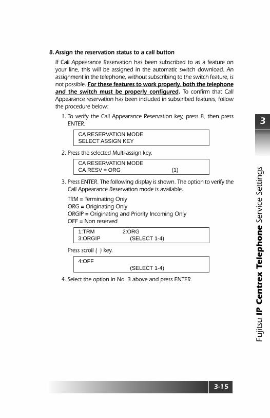
8. Assign the reservation status to a call button
If Call Appearance Reservation has been subscribed to as a feature onyour line, this will be assigned in the automatic switch download. Anassignment in the telephone, without subscribing to the switch feature, isnot possible. For these features to work properly, both the telephoneand the switch must be properly configured. To confirm that CallAppearance reservation has been included in subscribed features, followthe procedure below:
1. To verify the Call Appearance Reservation key, press 8, then pressENTER.
2. Press the selected Multi-assign key.
3. Press ENTER. The following display is shown. The option to verify theCall Appearance Reservation mode is available.
TRM = Terminating OnlyORG = Originating OnlyORGIP = Originating and Priority Incoming OnlyOFF = Non reserved
Press scroll ( ) key.
4. Select the option in No. 3 above and press ENTER.
CA RESERVATION MODESELECT ASSIGN KEY
CA RESERVATION MODECA RESV = ORG (1)
1:TRM 2:ORG3:ORGIP (SELECT 1-4)
4:OFF (SELECT 1-4)
3-16
Fujitsu
IP C
en
trex Te
leph
on
e Service Settin
gs
3
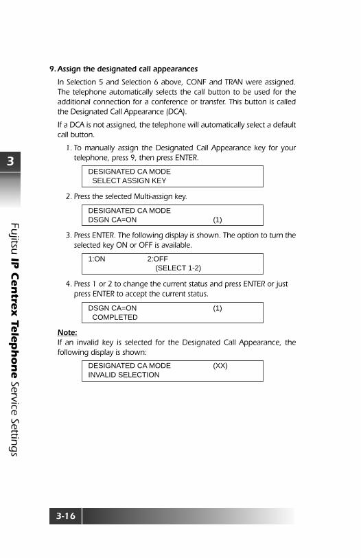
9. Assign the designated call appearances
In Selection 5 and Selection 6 above, CONF and TRAN were assigned.The telephone automatically selects the call button to be used for theadditional connection for a conference or transfer. This button is calledthe Designated Call Appearance (DCA).
If a DCA is not assigned, the telephone will automatically select a defaultcall button.
1. To manually assign the Designated Call Appearance key for yourtelephone, press 9, then press ENTER.
2. Press the selected Multi-assign key.
3. Press ENTER. The following display is shown. The option to turn theselected key ON or OFF is available.
4. Press 1 or 2 to change the current status and press ENTER or justpress ENTER to accept the current status.
Note:If an invalid key is selected for the Designated Call Appearance, thefollowing display is shown:
DESIGNATED CA MODE SELECT ASSIGN KEY
DESIGNATED CA MODEDSGN CA=ON (1)
1:ON 2:OFF (SELECT 1-2)
DSGN CA=ON (1) COMPLETED
DESIGNATED CA MODE (XX)INVALID SELECTION

3-17
Fujit
su IP C
en
trex T
ele
ph
on
e S
ervi
ce S
ettin
gs
3
Subscribed Feature Assigned FA SRS-12i SRS-24iAssigned FI Assigned FI
3 way conference FA 18 18 18
FA 60 18 18
Drop FA 19 19 19
FA 62 19 19
Transfer FA 20 20 20
FA 61 20 20
Message Waiting FA 63 MSG LED MSG LED
Call Exclusion FA 59 4 15
Privacy (Bridged Call FA 58 5 16Exclusion)
Call Forwarding FA 57 6 17Variable
Feature Activator and Button Placement
FA: Feature ActivatorFI: Feature Indicator

3-18
Fujitsu
IP C
en
trex Te
leph
on
e Service Settin
gs
3
SNTP Server Address Setup (Option 18)
The default SNTP Server Address is set upon shipment from the manufacturer.The SNTP server IP Address can be obtained from the DHCP server if thatoption is provided. In order to change the address, follow the steps below:
1. Press OPTIONS, numeric key, “1”, “8”, then ENTER.
2. Press ENTER.
3. Enter 4 digits of numeric password (see User Password Registration inchapter 4). Then, ENTER.Factory Default User Password - 9999
4. To overwrite, enter the SNTP server IP address. Press “#” key when theinput of a period (.) is required. In case of no support, press CLEAR tomake this section blank.
5. Press ENTER.
Press either asterisk (*) to go back to sub-menu or OPTIONS to exit theoption menu.
Note:If this option is used and the Telephone shows a “?” in the Date & Timedisplay, the SNTP Server and the Telephone have not established aconnection.
SNTP ADR REGISTRATION
ENTER USER PASSWORD
ENTER USER PASSWORD ****
ENTER SNTP ADDRESSNT=10.36.213.210
COMPLETED

3-19
Fujit
su IP C
en
trex T
ele
ph
on
e S
ervi
ce S
ettin
gs
3
Daylight Savings Setting (Option 21)
The Fujitsu SRS 12i / 24i IP Centrex Telephone allows the user to select DaylightSaving Time Setup when utilizing SNTP.
1. Press OPTIONS, numeric key “2”, “1”, then ENTER.
2. Press ENTER.
3. Enter 1 if Daylight Saving time is in effect.
4. Press ENTER.
Press either asterisk (*) to go back to sub-menu or OPTIONS to exit the optionmenu.
DAYLIGHT SAVING SETTING SUPPORT
1=SUPPORT 2=NO SUPPORT (SELECT 1-2)
1=SUPPORT 2=NO SUPPORT (SELECT=1)
SUPPORTED COMPLETED

3-20
Fujitsu
IP C
en
trex Te
leph
on
e Service Settin
gs
3
Time Zone Setup (Option 22)
The Fujitsu SRS 12i / 24i IP Centrex Telephone allows for many different timezones. The Time Zone setup is necessary when utilizing SNTP.
1. Press OPTIONS, numeric key “2”, “2”, then ENTER.
If Time Zone was already set up, the last time zone will be displayed. Thedefault Time Zone (Eastern – U.S. & Canada) is set upon shipment fromFujitsu.
2. Press ENTER.
Press (down)
3. Key the number corresponding to your Time Zone and press ENTER.Below example shows selection of 4: PT for Pacific Time.
Note:ET: Eastern Time (U.S. & Canada) – GMT - 5:00CT: Central Time (U.S., Canada & Mexico) – GMT - 6:00MT: Mountain Time (U.S., Canada & Mexico) – GMT - 7:00PT: Pacific Time (U.S., Canada & Mexico) – GMT – 8:00AK: Alaska – GMT – 9:00HI: Hawaii – GMT – 10:00
Press either asterisk (*) to go back to sub-menu or OPTIONS to exit the optionmenu.
TIME ZONE REGISTRATION EASTERN
1: ET 2: CT3: MT (SELECT 1-6)
4: PT 5: AK6: HI (SELECT 1-6)
PACIFIC TIME COMPLETED

3-21
Fujit
su IP C
en
trex T
ele
ph
on
e S
ervi
ce S
ettin
gs
3
Jitter Buffer Size (Option 26)
This feature allows the user to setup how many packets of voice data arebuffered. The default setting has been set upon shipment from themanufacturer. Refer to Appendix D, Jitter Buffer for more information aboutthis setting. To make changes, follow the steps below:
1. Press OPTIONS, numeric key, “2”, “6”, then ENTER.
2. Press ENTER.
3. Enter 8 digits of numeric administrator password (see AdministratorPassword Registration in chapter 4). Then ENTER.
*Factory default Administrator Password – 99999999
4. The default Jitter Buffer has been already set upon shipment.
Enter buffer number in the range of 0 ~ 7 for G.711 buffer.
5. Press ENTER.
Enter buffer number the range of 0 ~ 2.
6. Press ENTER.
Press either asterisk (*) to go back to sub-menu or OPTIONS to exit the optionmenu.
JITTER BUFFERG.711=0 G.729=2
ENTER ADM PASSWORD
ENTER ADM PASSWORD ********
G.711 JITTER BUFFERJITTER=0 (SELECT 0-7)
G.711 JITTER BUFFERJITTER=3 (SELECT 0-7)
G.729 JITTER BUFFERJITTER=2 (SELECT 0-2)
G.729 JITTER BUFFERJITTER=1 (SELECT 0-2)
G.711=3 G.729=1 COMPLETED

3-22
Fujitsu
IP C
en
trex Te
leph
on
e Service Settin
gs
3
TOS / Diffserv Setup (Option 23)
The Type of Service (TOS) and Diffserv settings provide adjustable parametersto modify the quality of service desired for voice traffic. Refer to Appendix A,QoS Setting for more details. To make changes, follow the steps below:
To set-up TOS, follow the steps below:
1. Press OPTIONS, numeric key “2”, “3”, then ENTER.
2. Press ENTER.
3. Enter 8 digits of numeric Administrator password (see AdministratorPassword Registration in chapter 4). Then ENTER.
*Factory default Administrator Password – 99999999
4. Press 1 then ENTER.
5. If TOS has been already set up, the last TOS level is displayed. Thedefault signaling value (5) is set upon the shipment from themanufacturer.
6. Key selected TOS value from the range of 0 – 7, then press ENTER.
7. If Voice value has been already set up, the last Voice level is displayed.The default voice value (5) is set upon the shipment from themanufacturer.
Select the value from the range of 0-7.
TOS / DIFFSERV SETTINGTOS S=5 V=5
ENTER ADM PASSWORD
ENTER ADM PASSWORD ********
1: TOS 2: DIFFSERV(SELECT 1-2)
TOS SETTINGSIGNALING=5 (SELECT 0-7)
TOS SETTINGSIGNALING=7 (SELECT 0-7)
TOS SETTINGVOICE=5 (SELECT 0-7)
TOS SETTINGVOICE=6 (SELECT 0-7)

3-23
Fujit
su IP C
en
trex T
ele
ph
on
e S
ervi
ce S
ettin
gs
3
Then, press ENTER.
Press either asterisk (*) to go back to sub-menu or OPTIONS to exit theoption menu.
To set-up Diffserv, follow the steps below:
1. Press OPTIONS, numeric key “2”, “3”, then ENTER.
2. Press ENTER.
3. Enter 8 digits of numeric Administrator password (see AdministratorPassword Registration in chapter 4). Then ENTER.
*Factory default Administrator Password – 99999999
4. Press 2, then ENTER.
5. If Diffserv has been already set up, the last Diffserv level is displayed.The default signaling value (101110) is set upon the shipment from themanufacturer.
6. Key 6 digits of Diffserv, then press ENTER.
You can clear and re-enter the value by pressing CLEAR before saving thevalue.
TOS S=7 V=6COMPLETED
TOS / DIFFSERV SETTINGTOS S=4 V=0
ENTER ADM PASSWORD
ENTER ADM PASSWORD ********
1: TOS 2: DIFFSERV(SELECT 1-2)
DIFFSERV SETTINGSIGNALING=101110 (0-1)
DIFFSERV SETTINGSIGNALING=101010 (0-1)

3-24
Fujitsu
IP C
en
trex Te
leph
on
e Service Settin
gs
3
7. You will need to set-up a voice value.
Key 6 digits of voice value.
8. You can clear and re-enter the value by pressing CLEAR before savingthe value. Then, press ENTER.
Press either asterisk (*) to go back to sub-menu or OPTIONS to exit theoption menu.
DIFFSERV SETTINGVOICE=101110 (0-1)
DIFFSERV SETTINGVOICE=111000 (0-1)
DS S=101010 V=111000COMPLETED

3-25
Fujit
su IP C
en
trex T
ele
ph
on
e S
ervi
ce S
ettin
gs
3
RTP Port Registration (Option 24)
Real Time Transport Protocol (RTP) is a thin protocol providing support forcontent identification, timing reconstruction, loss detection and security. Tochange the value for the RTP port, follow the steps below:
1. Press OPTIONS, numeric key “2”, “4”, then ENTER.
2. Press ENTER.
3. Enter 8 digits of numeric password (see Administrator PasswordRegistration in chapter 4). Then, ENTER.
*Factory default Administrator Password – 99999999
4. The default RTP Port has been set upon shipment from the manufacturer.To overwrite, simply enter the new RTP Port address. The set will acceptan even number between 1024 - 65532. Factory Default - 16384.
5. Press ENTER.
Press either asterisk (*) to go back to sub-menu or OPTIONS to exit the optionmenu.
RTP PORT REGISTRATIONPORT=16384
ENTER ADM PASSWORD
ENTER ADM PASSWORD ********
RTP PORT REGISTRATIONPORT = 16384 (1024-65532
PORT=16400 COMPLETED

3-26
Fujitsu
IP C
en
trex Te
leph
on
e Service Settin
gs
3
Optional FTP Address Setup (Option 97)
This allows the System Administrator to change the FTP address for theirspecific location. The default FTP address is setup upon the shipment fromthe manufacturer.
1. Press OPTIONS, numeric key “9”, “7”, then ENTER.
2. Press ENTER.
3. Enter 8 digits of numeric password (see Administrator PasswordRegistration in chapter 4). Then, ENTER.
*Factory Default Administrator Password – 99999999
4. The default FTP address is already set up as shown below:
Enter a new FTP Address.
Press “#” key when the input of a dot (.) is required.
5. Press ENTER.
Press either asterisk (*) to go back to sub-menu or OPTIONS to exit the optionmenu.
FTP ADR REGISTRATIONFTP=10.36.213.210
ENTER ADM PASSWORD
ENTER ADM PASSWORD ********
ENTER FTP ADDRESSFTP=10.36.213.210
ENTER FTP ADDRESSFTP=10.
ENTER FTP ADDRESSFTP=10.36.215.155
10.36.215.155COMPLETED

4-1 Fujit
su IP C
en
trex T
ele
ph
on
e P
assw
ord
Set
ting
s
4
CHAPTER 4 – PASSWORD SETTINGS
User Password Registration (Option 19)
The User Password registration is necessary in order to prevent unauthorizedentry into the telephone set. The User Password is used to access DHCP, IPAddress, Subnet Mask, Default Gateway Address, Feature Gateway Address,and SNTP.
1. Press OPTIONS, numeric key “1”, “9”, then ENTER.
2. Press ENTER.
3. Enter current 4 digits of numeric password. Then ENTER.
* Factory Default User Password - 9999
4. Enter new 4 digits of numeric password. Then ENTER.
The new password will be displayed on the screen.
Note:Asterisk (*) and pound (#) keys cannot be used in the password.
Press either asterisk (*) to go back to sub-menu or OPTIONS to exit the optionmenu.
USER PW REGISTRATION
ENTER USR PASSWORD
ENTER USR PASSWORD ****
ENTER NEW PASSWORD 1234
1234 COMPLETED

4-2
Fujitsu
IP C
en
trex Te
leph
on
e Passw
ord
Setting
s
4
Administrator Password Registration (Option 27)
The Administrator Password registration is necessary in order to preventunauthorized entry into the telephone set. The Administrator Password isused to access options menus such as Time Zone, TOS, RTP Port, MAC Address,Jitter Buffer, and Alias.
1. Press OPTIONS, numeric key “2”, “7”, then ENTER.
2. Press ENTER.
3. Enter current 8 digits of numeric password. Then, ENTER.
4. Enter new 8 digits of numeric password. Then, ENTER.
The new password will be displayed on the screen.
Note:Asterisk (*) and pound (#) keys cannot be used in the password.
Press either asterisk (*) to go back to sub-menu or OPTIONS to exit the optionmenu.
ADMIN PW REGISTRATION
ENTER ADM PASSWORD
ENTER ADM PASSWORD ********
ENTER NEW PASSWORD 12345678
12345678 COMPLETED

5-1
Fujit
su IP C
en
trex T
ele
ph
on
e
5
Soft
war
e D
ow
nlo
ad
CHAPTER 5 – SOFTWARE DOWNLOAD
Optional FTP Address Setup (Option 97)
Updating the application software is a very easy process. The set can upgradefrom the assigned FTP server address specified in menu option, OptionalFTP Address Setup (Option 97).
WARNING:While downloading the new software, DO NOTREMOVE POWER OR NETWORK from the set. ContactFNC TAC at 1-800-228-4736 if network connection orpower is lost.
1. Press OPTIONS, numeric key “9”, “8”, then ENTER.
2. Press ENTER.
3. Enter 8 digits of numeric password (see Administrator PasswordRegistration in chapter 4).
* Factory Default User Password - 99999999
4. Press ENTER.
APPLICATION UPGRADE
ENTER ADM PASSWORD
ENTER ADM PASSWORD ********
APPLICATION UPGRADE(1: YES 2: NO) (SELECT 1-2)

5-2
Softw
are Do
wn
load
5
Fujitsu
IP C
en
trex Te
leph
on
e
5. Press 1, then ENTER for YES. Or press 2, for NO then ENTER to cancelthe operation.
When 1: YES is selected, the set will go to the FTP site and begin thedownload, the following messages will be shown:
When complete the following message will be displayed:
The set will then restart and reconnect to the service.
FTP DOWNLOAD.....
NETWORK MONITORFTP D/L Rx xxxx
NETWORK MONITORFTP D/L Erasing
NETWORK MONITORFTP D/L Programming
FTP DOWNLOAD OK
6-1
Fujit
su IP C
en
trex T
ele
ph
on
e
6
Mas
ter
Cle
ar &
Pas
ww
or d
Res
et
CHAPTER 6 – MASTER CLEAR & PASSWORD RESET
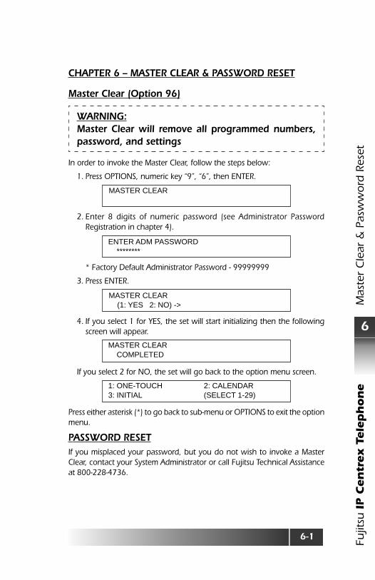
Master Clear (Option 96)
WARNING:Master Clear will remove all programmed numbers,password, and settings
In order to invoke the Master Clear, follow the steps below:
1. Press OPTIONS, numeric key “9”, “6”, then ENTER.
2. Enter 8 digits of numeric password (see Administrator PasswordRegistration in chapter 4).
* Factory Default Administrator Password - 99999999
3. Press ENTER.
4. If you select 1 for YES, the set will start initializing then the followingscreen will appear.
If you select 2 for NO, the set will go back to the option menu screen.
Press either asterisk (*) to go back to sub-menu or OPTIONS to exit the optionmenu.
PASSWORD RESETIf you misplaced your password, but you do not wish to invoke a MasterClear, contact your System Administrator or call Fujitsu Technical Assistanceat 800-228-4736.
MASTER CLEAR
ENTER ADM PASSWORD ********
MASTER CLEAR (1: YES 2: NO) ->
MASTER CLEAR COMPLETED
1: ONE-TOUCH 2: CALENDAR3: INITIAL (SELECT 1-29)

A-1
Fujit
su IP C
en
trex T
ele
ph
on
e E
rro
r M
essa
ges
A
APPENDIX A – ERROR MESSAGES
Various messages are displayed to describe connection or command status.
Table A-1 Connection Status Messages
Connection Status Messages BCS (Circuit-switched)Cause# Message Displayed Description
001 INVALID NUMBER Unassigned number002 NO ROUTE No route to specific network003 NO ROUTE No route to destination006 CHANNEL UNACCEPTABLE Not acceptable for use by switch007 Call awarded and being delivered in an
established protocol016 Normal; clearing017 BUSY Called user busy018 NOT ASSIGNED Called user not responding019 NOT ACCEPTED User alerted, no answer021 CALL REJECTED Call rejected022 NUMBER CHANGED Number called has been changed026 Non-selected user clearing027 NOT SELECTED Destination out of order028 INVALID NUMBER Format invalid or number incomplete029 FACILITY REJECTED Requested facility rejected030 Response to station inquiry031 Normal; unspecified034 B-CHANNEL BUSY No B-channel available035 Call queued038 OUT OF ORDER Network Out of Order041 Temporary failure042 NETWORK BUSY Network congested043 ACCESS INFORMATION User information discarded
DISCARDED044 REQUESTED CHANNEL Exclusive channel cannot be used
NOT AVAILABLE047 RESOURCE UNAVAILABLE, Downloading facility not available
UNSPECIFIED050 FACILITY N/A Requested facility not subscribed051 SERVICE NG Service request incompatible with service
request052 OUTGOING CALL BARRED Outgoing calls barred053 SERVICE NG Service operation violated054 CALLED BARRED Incoming calls barred057 BEARER TYPE NOT AUTHORIZED058 BEARER TYPE Bearer capability not presently
NOT PRESENTLY AVAILABLE available; try again
A-2
Fujitsu
IP C
en
trex Te
leph
on
e Erro
r Messag
es
A
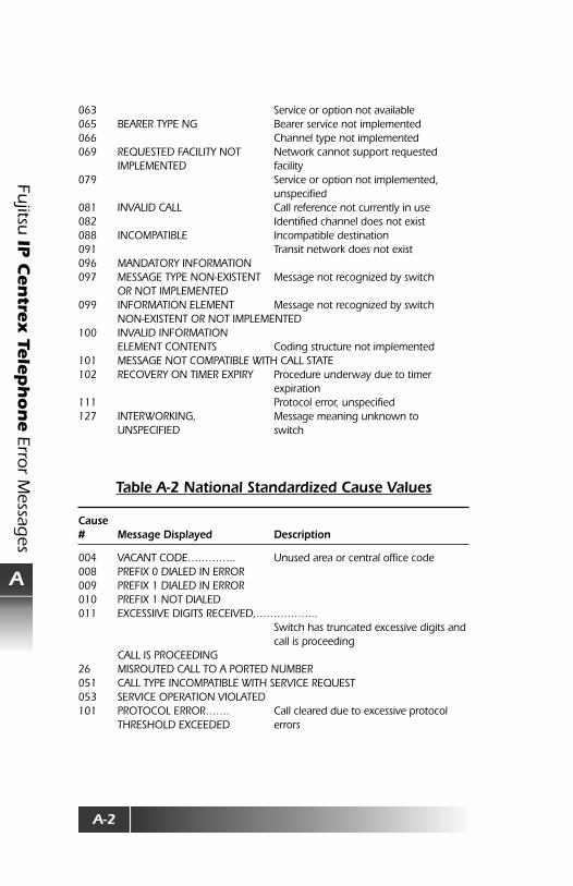
063 Service or option not available065 BEARER TYPE NG Bearer service not implemented066 Channel type not implemented069 REQUESTED FACILITY NOT Network cannot support requested
IMPLEMENTED facility079 Service or option not implemented,
unspecified081 INVALID CALL Call reference not currently in use082 Identified channel does not exist088 INCOMPATIBLE Incompatible destination091 Transit network does not exist096 MANDATORY INFORMATION097 MESSAGE TYPE NON-EXISTENT Message not recognized by switch
OR NOT IMPLEMENTED099 INFORMATION ELEMENT Message not recognized by switch
NON-EXISTENT OR NOT IMPLEMENTED100 INVALID INFORMATION
ELEMENT CONTENTS Coding structure not implemented101 MESSAGE NOT COMPATIBLE WITH CALL STATE102 RECOVERY ON TIMER EXPIRY Procedure underway due to timer
expiration111 Protocol error, unspecified127 INTERWORKING, Message meaning unknown to
UNSPECIFIED switch
Table A-2 National Standardized Cause Values
Cause# Message Displayed Description
004 VACANT CODE………….. Unused area or central office code008 PREFIX 0 DIALED IN ERROR009 PREFIX 1 DIALED IN ERROR010 PREFIX 1 NOT DIALED011 EXCESSIIVE DIGITS RECEIVED,……………...
Switch has truncated excessive digits andcall is proceeding
CALL IS PROCEEDING26 MISROUTED CALL TO A PORTED NUMBER051 CALL TYPE INCOMPATIBLE WITH SERVICE REQUEST053 SERVICE OPERATION VIOLATED101 PROTOCOL ERROR……. Call cleared due to excessive protocol
THRESHOLD EXCEEDED errors

A-3
Fujit
su IP C
en
trex T
ele
ph
on
e E
rro
r M
essa
ges
A
Table A-3 Network Specific Cause Values
Cause# Message Displayed Description
008 CALL IS PROCEEDING Call cannot be cleared due to other users013 SERVICE DENIED028 SPECIAL INTERCEPT ANNOUNCEMENT029 SPECIAL INTERCEPT Announcement that access code is not
ANNOUNCEMENT: definedUNDEFINED CODE
030 SPECIAL INTERCEPT Announcement that number isANNOUNCEMENT: unassignedNUMBER UNASSIGNED
031 SPECIAL INTERCEPT Announcement that call is blocked dueANNOUNCEMENT: CALL to group restrictionBLOCKED DUE TO GROUPRESTRICTION
090 SEGMENTATION ERROR Parameter downloading message error091 REASSEMBLY ERROR Parameter downloading error101 PROTOCOL ERROR, THRESHOLD Call cleared due to excessive protocol
EXCEEDED errors
Table A-4 Uniform Cause Values
Cause # Message Displayed
003 NO ROUTE TO DESTINATION016 NORMAL CLEARING017 USER BUSY018 NO USER RESPONDING019 USER ALERTING, NO ANSWER021 CALL REJECTED022 NUMBER CHANGED027 DESTINATION OUT OF ORDER034 CIRCUIT/CHANNEL CONGESTION057 BEARER CAPABILITY NOT AUTHORIZED065 BEARER CAPABILITY NOT IMPLEMENTED

A-4
Fujitsu
IP C
en
trex Te
leph
on
e Erro
r Messag
es
A
Table A-5 LAN Connection Status Messages
Message Displayed Description
Check LAN cable LAN cable is missing or not connected to thenetwork
DHCP Outage The DHCP server is not responding
DHCP Reboot Telephone resets based on different IP addressassignment from DHCP Server
DHCP Lease Expired DHCP Server has not issued an IP address toTelephone
Network Outage Setup data incorrect or connection failure withFeature Gateway. (IP Address, Subnet Mask,Default Gateway Address, Feature GatewayAddress, Feature Gateway Alias)

B-1
Fujit
su IP C
en
trex T
ele
ph
on
e A
pp
end
ix B
- Se
lf-Te
stin
g
B
APPENDIX B – SELF-TESTING
The telephone has a self-test mode that performs tests, which include thefollowing:
• LED test• Key test (22)• Tone test (16)• Ringer test (17)• LCD test (11)• Hold Tone Check (18)• Key Touch Tone test (19)• Ping test (9)• DSP Coder Loopback• MAC Address test (20)
Performing Self-TestNote:The set cannot originate or receive calls during the self-test. Enter password“12345678” then “*”. If a mistake is made entering the password, press “#”key to return to a password input state.
1. Unplug the power cord from the DC power connector.
2. Press and hold down both “1” and “3” simultaneously on numeric keypadas power is reapplied by plugging the DC jack into the telephone. Keepthem down until the automatic LED test begins.
When the LED test is complete, this screen appears:
Enter password “12345678” then “*”.
It is now ready to do the Self-Test
Test Program V00L0040
Test Program V00L0040Password:
Test Program V00L0040Password: ********
Test Program V00L0040Password: ********
Test Program
B-2
Fujitsu
IP C
en
trex Te
leph
on
e A
pp
end
ix B - Self-Testin
g
B
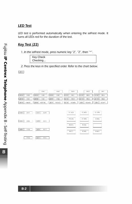
LED Test
LED test is performed automatically when entering the self-test mode. Itturns all LEDs red for the duration of the test.
Key Test (22)
1. In the self-test mode, press numeric key “2”, ”2”, then “*”.
2. Press the keys in the specified order. Refer to the chart below.
Key CheckChecking...
B-3
Fujit
su IP C
en
trex T
ele
ph
on
e A
pp
end
ix B
- Se
lf-Te
stin
g
B
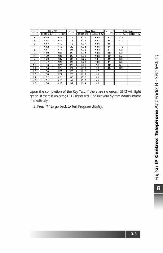
Upon the completion of the Key Test, if there are no errors, LE12 will lightgreen. If there is an error, LE12 lights red. Consult your System Administratorimmediately.
3. Press “#” to go back to Test Program display.

B-4
Fujitsu
IP C
en
trex Te
leph
on
e A
pp
end
ix B - Self-Testin
g
B
Tone Test (16)
1. In the self-test mode, press numeric key “1”, “6”, then “*”.
2. Press numeric key “1”, then “*”.
You should be able to hear tone from the handset.
3. Press numeric key “2”, then “*”.
You should be able to hear a tone from the Speaker.
Checking the volume is possible by pressing K45 and K44 (Softkey and ).
4. Press “#” to go back to Test Program display.
Ringer Test (17)
1. In the self-test mode, press numeric key “1”, “7”, then “*”.
2. Press numeric key “1” then “*”.
You should be able to hear a ringing sound.
3. Press numeric key “2” then “*”.
You should be able to hear a melody.
Checking the volume is possible by pressing K45 and K44 (Softkey and ).
4. Press “#” to go back to Test Program display.
Tone CheckHS=1/SP=2
Tone CheckHandset ◆
Tone CheckSpeaker ◆
Ringer CheckRing=1/Melody=2
Ringer CheckMelody
Ringer CheckRing ◆

B-5
Fujit
su IP C
en
trex T
ele
ph
on
e A
pp
end
ix B
- Se
lf-Te
stin
g
B
LCD Test (11)
1. In the self-test mode, press numeric key “1”, “1”, then “*”.
2. Press numeric key “1”, then “*”.
3. Press “*”
4. Press numeric key “2”, then “*”. All pixels will be turned on.
5. Press “*”.
6. Press numeric key “3”, then “*”. A blank screen will be displayed.
7. Press “#” to go back to Test Program display.
LCD CheckABD.=1/■ =2/CLEAR=3
LCD CheckABD.=1/■ =2/CLEAR=3
LCD CheckABD.=1/■ =2/CLEAR=3
ABCDEFGHIJKLMNOPQRSTUVWXabcdefghijklmnopqrstuvwx
■■■■■■■■■■■■■■■■■■■■■■■■■■■■■■■■■■■■■■■■■■■■■■■■■■

B-6
Fujitsu
IP C
en
trex Te
leph
on
e A
pp
end
ix B - Self-Testin
g
B
Hold Tone Check (18)
1. In the self-test mode, press numeric key “1”, “8”, then “*”.
2. Press numeric key “1”, then “*”.
You should be able to hear music from the handset.
3. Press numeric key “2”, then “*”.
You should be able to hear music from the speaker.
4. Press “#” to go back to Test Program display.
Key Touch Tone Test (19)
1. In the self-test mode, press numeric key “1”, “9”, then “*”.
You should be able to hear continuous audible tone from speaker.
2. Press “#” to go back to Test Program display.
Hold Tone CheckHS=1/SP=2
Hold Tone CheckHandset
Hold Tone CheckSpeaker
Touch Tone Check

B-7
Fujit
su IP C
en
trex T
ele
ph
on
e A
pp
end
ix B
- Se
lf-Te
stin
g
B
Ping Test (9)
1. In the self-test mode, press numeric key “9”, then “*”.
2. Press following IP address by using the numeric keys in order such as192*100*.
3. When the check is complete and if no problems were found, thefollowing screens will be displayed as shown below:
Upon the successful completion of the Ping check, LED LE10 and the SPKRLED will light green.
In case of error, the following screens will be shown:
At this time, LED LE10 will light red. Consult your System Administratorimmediately.
Ping Transmission09-
09-192.168.1.100pinging
PING:192.168.1.100Reply...time=xxms
Reply...time=xxmsReply...time=xxms
Reply...time=xxmsPing Complete
PING:192.168.1.100Requested time out
Requested time outRequested time out
Requested time outPing Complete
B-8
Fujitsu
IP C
en
trex Te
leph
on
e A
pp
end
ix B - Self-Testin
g
B
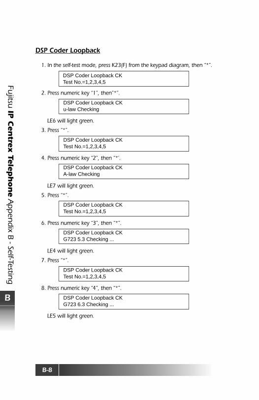
DSP Coder Loopback
1. In the self-test mode, press K23(F) from the keypad diagram, then “*”.
2. Press numeric key “1”, then”*”.
LE6 will light green.
3. Press “*”.
4. Press numeric key “2”, then “*’.
LE7 will light green.
5. Press “*”.
6. Press numeric key “3”, then “*”.
LE4 will light green.
7. Press “*”.
8. Press numeric key “4”, then “*”.
LE5 will light green.
DSP Coder Loopback CKTest No.=1,2,3,4,5
DSP Coder Loopback CKu-law Checking
DSP Coder Loopback CKTest No.=1,2,3,4,5
DSP Coder Loopback CKA-law Checking
DSP Coder Loopback CKTest No.=1,2,3,4,5
DSP Coder Loopback CKG723 5.3 Checking ...
DSP Coder Loopback CKTest No.=1,2,3,4,5
DSP Coder Loopback CKG723 6.3 Checking ...

B-9
Fujit
su IP C
en
trex T
ele
ph
on
e A
pp
end
ix B
- Se
lf-Te
stin
g
B
9. Press “*”.
10. Press numeric key “5”, then “*”.
LE2 will light green.
11. Press “#” to go back to Test Program display.
Note:If the LEDs light red instead of green, contact your System Administrator orcall Fujitsu Technical Assistance at 800-228-4736.
DSP Coder Loopback CKTest No.=1,2,3,4,5
DSP Coder Loopback CKG729A Checking ...

B-10
Fujitsu
IP C
en
trex Te
leph
on
e A
pp
end
ix B - Self-Testin
g
B
MAC Address Display (20)
1. In the self-test mode, press numeric key “2”, “0”, then “*”.
2. Press “#” to return to the Test Program display.
Ending Self-Test
To end Self-Test, simply remove power and then reapply it.
MAC Address00:00:0e:xx:xx:xx

C-1
Fujit
su IP C
en
trex T
ele
ph
on
e A
pp
end
ix C
- M
isce
llan
eou
s an
d G
loss
ary
C
APPENDIX C – MISCELLANEOUS AND GLOSSARY
QoS Settings (TOS and Diffserv)
The SRS-12i / 24i supports both the TOS and Diffserv parameters as QoSsettings in the IP packet header. (Based on IEEE802.1p)
The Fujitsu IP Centrex Telephone sets can utilize and modify both of theseparameters to gain a desired level of QoS. This feature should be administeredby the System Administrator, and the type of QoS (TOS/Diffserv) is selectedbased upon the System Administrator’s discretion.
Drawing 1 shows the relationship of those QoS parameters.
Drawing 1: Correlation between TOS and DSCP
The QoS parameters should be set up by the System Administrator. Drawing2 shows how precedence value in TOS field and DSCP value in Diffservcorresponds. Recommended QoS value with appropriate entry method beshown.

C-2
Fujitsu
IP C
en
trex Te
leph
on
e A
pp
end
ix C - M
iscellaneo
us an
d G
lossary
C
Drawing 2 : Mapping of DSCP and TOS precedence
Note: Shaded parts – default setting:
TOS Mode Diffserv Mode(Precedence) (DSCP)
Voice 5 101110Signaling(*): 5 101110* RAS, Q931

C-3
Fujit
su IP C
en
trex T
ele
ph
on
e A
pp
end
ix C
- M
isce
llan
eou
s an
d G
loss
ary
C
Jitter Buffer Setting Parameter Setting
*G.711 Default Value is 0*G.729A Default Value is 0
Port Number
RAS: 1719, Q:931:1720
Automatic Adjust Voice Packet Length
SRS-12i / 24i automatically adjusts its voice packet length and type of CODECbased on the preference list registered by Feature Gateway. Supported voicepacket lengths are as follows:
RTP Port
Variable Range: 1024 - 65532Default: 16384
RTCP
Variable (RTP+1): 1025 - 65533Default: 16385

C-4
Fujitsu
IP C
en
trex Te
leph
on
e A
pp
end
ix C - M
iscellaneo
us an
d G
lossary
C
Glossary
CA Call appearance of a telephone number.
Call button A button available for a voice call.
CFD/CFB Call forwards incoming calls to a pre-assigned destinationnumber when you “don’t answer” or when your line is “busy”;set up at service subscription .
CFV/CFU Call forwards incoming calls to a number you select; activatedby user when needed.
CNI Provides the incoming calling line number if available.
Conference Allow user to make conference call if subscribed.
DHCP Dynamic Host Configuration Protocol. A protocol which allowsa server to dynamically assign IP addresses to workstations.
Diffserv Differentiated Services (DiffServ or DS) is a protocol for specifyingand controlling network traffic by class so that certain types oftraffic get precedence.
DN Directory Number
G.711 An international standard encoding/decoding audio.
G.729 An international standard for encoding/decoding audio.
Gateway An entrance and exit into a communications network.
Hold Allows the user to place an active call on “hold”.
IP Internet Protocol. A DOD standard protocol designed for usein interconnected systems of packet-switched computercommunication networks.
Jitter Buffer Packet delivery and disposition management.
LAN Local Area Network. A geographically localized networkconsisting of both hardware and software.
MAC Media Access Control is an address that controls access to theshared medium by LAN-attached devices.
MSG Message waiting in voice mail.

C-5
Fujit
su IP C
en
trex T
ele
ph
on
e A
pp
end
ix C
- M
isce
llan
eou
s an
d G
loss
ary
C
RTP The Real-Time Transport Protocol (RTP) is an Internet protocolstandard that specifies a way for programs to manage the real-time transmission of multimedia data over either unicast ormulticast network services.
SNTP Simple Network Time Protocol. A simplified version of NTP –standard protocol used to synchronize system clocks on routersand computer systems throughout the Internet. The SNTPServer can be installed as a service; once configured, it willkeep your telephone’s clock correct up to fractions of a second.
SPID Service Profile Identifier, The SPID is an eight to 14 digit numberthat identifies the services ordered.
Subnet Mask A number that is used to identify a sub network so that IPaddresses can be shared on a LAN.
TOS Type of Service.
Transfer Allows for the redirection of an active call to another telephonenumber.
VLAN Virtual Local Area Network (VLAN) allows LAN users on differentphysical LAN segments priority access privileges across the LANbackbone.