abot-0004 chassis assembly guide
TRANSCRIPT

ABOT CHASSIS ASSEMBLY GUIDE
ABOT-0004
01/12
Features
• Abot assembly
• Distance sensor and servomotor data
Description
The guide for assembling the Abot robot chassis
Including the basic data
Datasheet−TEMPLATE−01/12

ABOT-0004 [Abot Chassis Assembly Guide ] Datasheet−−−−TEMPLATE−−−−01/12
2
Table of Contents
1. Introduction ........................................................................................ 3
2. Basic data .......................................................................................... 3
2.1 HSR-1425CR Continuous Rotation Servo ........................................................ 3
2.2 Pololu Carrier with Sharp GP2Y0D810Z0F Digital Distance Sensor 10cm ....... 4
3. Assembling Abot ................................................................................ 5
3.1 Assemble the wheels ........................................................................................ 5
3.2 Assemble the motors ........................................................................................ 6
3.3 Assemble the ball caster ................................................................................... 8
3.4 Assemble the Distance Sensor ......................................................................... 9
3.5 Assemble battery ............................................................................................ 10
3.6 Assemble control unit ...................................................................................... 11
3.7 Add yor own stuff ............................................................................................ 12

ABOT-0004 [Abot Chassis Assembly Guide ] Datasheet−−−−TEMPLATE−−−−01/12
3
1. Introduction
This document provides a step by step assembly guide for Abot
You can also find the Servo and Distance sensor basic data.
2. Basic data
2.1 HSR-1425CR Continuous Rotation Servo
HSR-1425CR Continuous Rotation Servo
Motor Ctrl (PWM) Yellow
Motor pwr (4.8-6.0V) Red
Motor GND Black
Control System Pulse Width Modulation 20 000uSec Frame
Neutral position 1 500uSec +/-50uSec
Direction Clock wise pulse traveling 1500 to 1900uSec
Operating Voltage 4.8 to 6.0V
Idle current 7.7mA
Running current 150mA no load

ABOT-0004 [Abot Chassis Assembly Guide ] Datasheet−−−−TEMPLATE−−−−01/12
4
2.2 Pololu Carrier with Sharp GP2Y0D810Z0F Digital Distance Sensor 10cm
Digital Distance Sensor
Square pad GND
operating voltage:
2.7 V to 6.2 V
VIN
digital out OUT
The square pad is ground, the middle pad is VIN (2.7 – 6.2 V), and the remaining pad is the sensor output, OUT.
The output, Vo, is driven low when the sensor detects an object; otherwise, the output is high.
The Pololu carrier board lets you interface with the GP2Y0D805 or GP2Y0D810 sensor using a three-pin 0.1"
connector, such as the included 3×1 straight male header strip and 3×1 right-angle male header strip.
Feature summary
• operating voltage: 2.7 V to 6.2 V
• average current consumption: 5 mA (typical)
• distance measuring range for GP2Y0D810Z0F: 2 cm to 10 cm (0.8" to 4")
• output type: digital voltage
• steady state response time: 2.56 ms typical (3.77 ms max)

ABOT-0004 [Abot Chassis Assembly Guide ] Datasheet−−−−TEMPLATE−−−−01/12
5
3. Assembling Abot
Tools required
• Screwdriver
• Drill with 2mm bit
3.1 Assemble the wheels
Unpack the motor
Remove the center screw
Use a 2mm drill on the 4 holes for wheel to horn assembly.

ABOT-0004 [Abot Chassis Assembly Guide ] Datasheet−−−−TEMPLATE−−−−01/12
6
Attach the horn to the wheel using 4x 2mm screews w/nut
3.2 Assemble the motors
To assemble one bracket you need these parts

ABOT-0004 [Abot Chassis Assembly Guide ] Datasheet−−−−TEMPLATE−−−−01/12
7
Assemble bracket to motor
Assemble motor to chassis

ABOT-0004 [Abot Chassis Assembly Guide ] Datasheet−−−−TEMPLATE−−−−01/12
8
Adjust to allign wheels before fasten
3.3 Assemble the ball caster
Open the pacage and remove the ball.
Attach the ball caster to the base plate with the two shortest screw’s (on the oposit side as the motors)

ABOT-0004 [Abot Chassis Assembly Guide ] Datasheet−−−−TEMPLATE−−−−01/12
9
Insert the white cylinders and insert the ball
3.4 Assemble the Distance Sensor
Unpack the sensor and solder the connector
Cutt the Velcron in a sutable size and glue to front bottom of base plate
Glue the other Velcron part to the sensor
ABOT-0004 [Abot Chassis Assembly Guide ] Datasheet−−−−TEMPLATE−−−−01/12
10
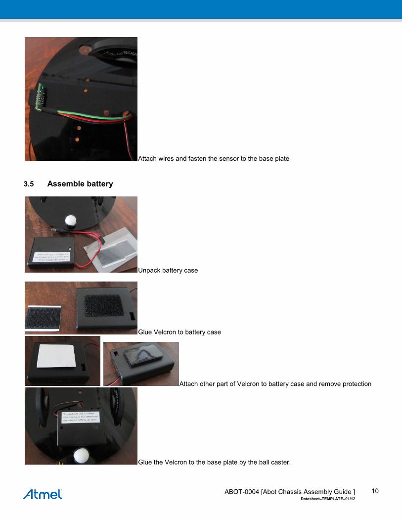
Attach wires and fasten the sensor to the base plate
3.5 Assemble battery
Unpack battery case
Glue Velcron to battery case
Attach other part of Velcron to battery case and remove protection
Glue the Velcron to the base plate by the ball caster.

ABOT-0004 [Abot Chassis Assembly Guide ] Datasheet−−−−TEMPLATE−−−−01/12
11
3.6 Assemble control unit A number of development boards from Atmel can be used as control unit. Bellow an example with the Raven kit (ATAVRRZRAVEN) and the MEGA-1284P Xplained (ATMEGA1284P-XPLD)
The wires can be “hidden” between the motors The Raven or XPLD kit can be fastend to the top of the motors with Velcron
Or behind the motor:

ABOT-0004 [Abot Chassis Assembly Guide ] Datasheet−−−−TEMPLATE−−−−01/12
12
3.7 Add yor own stuff It is easy to glue or screw new sensors etc. to the chassis.

Atmel Corporation
2325 Orchard Parkway
San Jose, CA 95131
USA
Tel: (+1)(408) 441-0311
Fax: (+1)(408) 487-2600
www.atmel.com
Atmel Asia Limited
Unit 01-5 & 16, 19F
BEA Tower, Millennium City 5
418 Kwun Tong Road
Kwun Tong, Kowloon
HONG KONG
Tel: (+852) 2245-6100
Fax: (+852) 2722-1369
Atmel Munich GmbH
Business Campus
Parkring 4
D-85748 Garching b. Munich
GERMANY
Tel: (+49) 89-31970-0
Fax: (+49) 89-3194621
Atmel Japan G.K.
16F Shin-Osaki Kangyo Building
1-6-4 Osaki
Shinagawa-ku, Tokyo 141-0032
JAPAN
Tel: (+81)(3) 6417-0300
Fax: (+81)(3) 6417-0370
© 2012 Atmel Corporation. All rights reserved. / Rev.: Datasheet−−−−TEMPLATE−−−−01/12
Atmel®, Atmel logo and combinations thereof, Enabling Unlimited Possibilities®, and others are registered trademarks or trademarks of Atmel Corporation or its
subsidiaries. Other terms and product names may be trademarks of others.
Disclaimer: The information in this document is provided in connection with Atmel products. No license, express or implied, by estoppel or otherwise, to any intellectual property right is granted by this document or in connection with the sale of Atmel products. EXCEPT AS SET FORTH IN THE ATMEL TERMS AND CONDITIONS OF SALES LOCATED ON THE ATMEL WEBSITE, ATMEL ASSUMES NO LIABILITY WHATSOEVER AND DISCLAIMS ANY EXPRESS, IMPLIED OR STATUTORY WARRANTY RELATING TO ITS PRODUCTS INCLUDING, BUT NOT LIMITED TO, THE IMPLIED WARRANTY OF MERCHANTABILITY, FITNESS FOR A PARTICULAR PURPOSE, OR NON-INFRINGEMENT. IN NO EVENT SHALL ATMEL BE LIABLE FOR ANY DIRECT, INDIRECT, CONSEQUENTIAL, PUNITIVE, SPECIAL OR INCIDENTAL DAMAGES (INCLUDING, WITHOUT LIMITATION, DAMAGES FOR LOSS AND PROFITS, BUSINESS INTERRUPTION, OR LOSS OF INFORMATION) ARISING OUT OF THE USE OR INABILITY TO USE THIS DOCUMENT, EVEN IF ATMEL HAS BEEN ADVISED OF THE POSSIBILITY OF SUCH DAMAGES. Atmel makes no representations or warranties with respect to the accuracy or completeness of the contents of this document and reserves the right to make changes to specifications and products descriptions at any time without notice. Atmel does not make any commitment to update the information contained herein. Unless specifically provided otherwise, Atmel products are not suitable for, and shall not be used in, automotive applications. Atmel products are not intended, authorized, or warranted for use as components in applications intended to support or sustain life.