about the manual - cdkn.orgcdkn.org/wp-content/uploads/2014/07/hp-artisans-module.pdfabout the...
TRANSCRIPT

1

ABOUT THE MANUAL This manual specifically looks at LC-CR construction for wet and hilly climate for artisans. The state of Himachal Pradesh acts as a model for similar wet hilly regions across the Indian subcontinent as well as South Asia. The target group includes artisans, masons and supervisors of sustainable/ low carbon habitat projects. The objective of the manual is to impart knowledge on constructing resource and energy efficient buildings. This manual aims to: • Provide basic principles and guidelines to masons
about good quality construction practices, in particular focusing on alternative, environment friendly building practices.
• Improve their skills and seeks to fill the gaps in their knowledge and understanding to upgrade the quality of their work.
• Reinforce the significance and the immense potential of their work to improve our living environment.
This manual is intended to serve as a practical guide for the capacity building of artisans in LC-CR construction.
This document is an output from a project funded by the UK Department for International Development (DFID) and the Netherlands Directorate-General for International Cooperation (DGIS) for the benefit of developing countries. However, the views expressed and information contained in it are not necessarily those of or endorsed by DFID or DGIS, who can accept no responsibility for such views or information or for any reliance placed on them. This publication has been prepared for general guidance on matters of interest only, and does not constitute professional advice. You should not act upon the information contained in this publication without obtaining specific professional advice. No representation or warranty (express or implied) is given as to the accuracy or completeness of the information contained in this publication, and, to the extent permitted by law, the entities managing the delivery of the Climate and Development Knowledge Network do not accept or assume any liability, responsibility or duty of care for any consequences of you or anyone else acting, or refraining to act, in reliance on the information contained in this publication or for any decision based on it. © Copyright Climate and Development Knowledge Network 2013. All content / information present here is the exclusive property of Development Alternatives (DA). The content / information contained here is correct at the time of publishing. The views expressed in this document do not necessarily reflect the views of any organization(s) associated with DA. This document contains details of a number of organizations, events, publications, projects and individuals. However, this does not imply that these entities are either endorsed or recommended by DA in preference to others of a similar nature. These entities shall not be liable for any damages incidental to the use of the information contained in this document. No material from here may be copied, modified, reproduced, republished, uploaded, transmitted, posted or distributed in any form without prior written permission from DA. Unauthorized use of the content / information appearing here may violate copyright, trademark and other applicable laws, and could result in criminal or civil penalties. © Development Alternatives 2013
CONTENTS Foreword 1. Wall technologies 1.1 Dhajji wall construction 1.2 Trombe wall construction 1.3 Cavity wall construction 1.4 Timber reinforced stone masonry 1.5 Bamboo superstructure 2. Roof technologies 2.1 Ferro cement channel roofing 2.2 Filler slab 3. Flooring 3.1 Bamboo flooring 4. Sanitation 4.1 Eco-san toilets
3

FOREWORD With rising temperatures and erratic weather patterns, climate change is one of the most pressing problems facing the world today. Threats associated with climate change are further compounded by the increasing pressure exponentially growing population is placing on natural resources. The construction sector, especially, has been identified as a high priority sector for action on this front. The construction sector is a resource and energy intensive sector. It contributes to large scale environmental degradation during extraction and transport phases as well to global climate change through increased carbon emissions. On the other hand, the exponentially growing sector contributes substantially to the national GDP, while employing over 18 million people in the country. On the other hand, the impacts of the changing climate like rising sea levels, increased occurrence of severe weather events and natural disasters, severe water shortages, etc. are also felt keenly by the sector and warrants immediate response. At the same time nationally and internationally, construction has been identified as a sector where large savings in energy and carbon emissions are possible. The manual seeks to address knowledge needs of masons with good experience in specific/ general construction practice and, preferably, also an orientation in alternative construction techniques. The content of the manual is also relevant to construction supervisors and for masons who want to independently manage construction assignments as small contractors for LCCR projects. The technologies have been chosen based on the following key parameters: • Reduced embodied energy and fuel consumption hence reduced carbon emissions • Reduced environmental damage through optimal resource use and waste utilization • Better thermal efficiency and comfort • Resistant to natural disasters • Aligned to local production in terms of material and skill availability • Cost efficiency

DHAJJI WALL CONSTRUCTION

INTRODUCTION Dhajji construction is a traditional building technique of the Kashmir mountains. In this construction system, the walls are made of timber frames within-fills of light thin panels made by close packaging of mud mortar, stone and ballast. In case of an earthquake, the small panels distribute the energy evenly.
COMPONENTS
TIMBER BOARDS
JOISTS
WALL PLATE
POSTS (MAIN FRAME)
STUDS (THINNER THAN FRAME)
HORIZONTAL BOARDS
BRACING BOARDS
BASE PLATE
PLINTH (STONE MASONRY)
LINTEL BOARDS / HEADER
JAMBS
SILL BOARD
FOUNDATION 1. Foundations must be at least 2 ft deep in solid ground (except on rock) and at least 2 ft wide. For 2 storey buildings, foundations should be at least 2’-6” wide. 2. Add a plinth of 1 ft on top of the foundation to keep the base plate away from the ground.
PLINTH 3. Finish the outer part of the top surface of the plinth with a slope towards outside to drain water away from the base plate. Keep the top surface irregular to avoid getting water trapped under the base plate.
INTRODUCTION
STEPS OF CONSTRUCTION

REINFORCEMENT 5. Use galvanized anchor rods with a thread or paint the rods with anti-corrosion paint before use. 6. Place the anchor rods while making the foundation and make sure that the rods are embedded in 1” of mortar all around (cement mortar protects against rust). Fill in mortar while raising the foundation and compact well. 7. Keep the first anchor rods 2 ft from the corner and place the following less than 6 ft apart.
WALLS 8. For the main frame use only the best timber available. The base plate should be in rot resistant wood (e.g. cedar) or be treated with wood preservatives. The posts of the main frame are made of timber with a minimal cross section of 4”x 4” placed at 6 ft spacing centre to centre. 9. For the secondary subdivision use timber half as thick as the posts (that is 2”x 4” instead of 4” x4”) and place it at 2 ft, 3 ft or 18” depending on the chosen final subdivision pattern. 10. Walls can be subdivided in various ways. The strength of the finished wall depends on the quality of connections and the number of bracing boards.
7
5
6
CARPENTRY CONNECTIONS 11. To fix the posts on the base plate, a mortise and tenon joint ensures the strongest connection. additional strength, the joint may be secured with two 6” nails.
11
12
8 10 9
12. To secure the joint against vertical movement, nail a strap or boards on both sides. Straps must not be thinner than 1/10” or 13 SWG (2.5mm) and should go all around the base plate.
13. Corner joints must be made with greatest care, as they are particularly at risk during an earthquake. Join the base plates with a cross lap joint. To ensure strength leave 1 ft of timber after the joint. 14. Secure the posts with two 6” nails driven diagonally through the joint.
13 14

15. Add blocking pads on all four sides and fix each of them on the base plate with two or three 4” nails. The outer pads should be wedge shaped and bigger to protect the base plate ends against rain.
PLASTERING & FLASHING 19. A good mud plaster mix is made of one third of clay, two thirds of sand and a fair amount of pine needles or straw. Look also for local expertise. Apply the plaster in several layers not exceeding ½” each. If you make the layers too thick, they will crack. For paint use white wash (lime). Don’t use synthetic paint, it doesn’t adhere properly on mud plaster. 20. To protect the wall against splashing rain, nail a timber board or a CGI sheet against the lower part of the wall structure (to both base plate and posts). 21. To avoid infiltration of water under the base plate it’s advisable to fix a galvanized metal flashing which covers both the base plate and the plinth beam.
16. Fix the post to the base plate to avoid uplift during a quake. If a strap is used, it must be 1/10” thick (13 SWG, 2.5mm). The strap should be made of galvanized iron. 17. Diagonal timber boards of 1” or 1 ½” thickness can replace the strap.
STONE INFILL 18. For the infills, use flat stones or bricks. Pack the stones neatly into the gaps with mud or lime mortar. The mortar layers should be around ½” thick and the proportion should not exceed one quarter of mortar for three quarters of stones. Fill remaining gaps with stone flakes.
1. Proportions: A square form is best. Don’t make buildings longer than 3 times their width. 2. Shape: Keep the shape of the building simple. Subdivide it into single blocks if necessary
1 2
15 16
17
18
19
20
21
DOs & DON’Ts

• Traditional Dhajji houses have proved to be
highly earthquake resistant in comparison with those made with modern building materials, have collapsed.
• Makes use of local resources instead of spending their money on costly transport of modern building materials.
3. Planning: Start with a simple volume and subdivide it into the rooms you need. Don’t proceed the other way around, by sticking rooms together in order to get the final form of the house. 4. Balance: Evenly distributed inner walls ensure equal strength of the buidling in all parts. Therefore don’t place all small rooms on one side and all big rooms on the other side of the house.
7. The length of a wall must not exceed 15 ft. If the wall is longer, it has to be braced in between, either by a buttress wall or a beam well connected to another wall in the same direction.
8. Windows and doors are weak points. make as few as possible. 9. Smaller windows are better than big ones. 10. Avoid placing all windows and doors in The same wall. Keep windows and doors at least 2 ft from the corners. 11. Verandas should not be deeper than 1/3 of the depth of the building. 12. Verandas placed in the middle of the building are better.
5. External walls: External walls without openings are strongest. Windows and verandas weaken the walls. Keep them to a minimum. 6. Shop window front: Avoid having a ‘shop window front’ taking up an entire side of the building. This side of the house will be weak and collapse quickly, leading to the collapse of the rest.
7
5
6
3
4
8
ADVANTAGES LIMITATIONS • Need well-trained and skilled masons for
construction. • Water proofing and termite control a
major concern
9 10
11 12

TROMBE WALL

A Trombe wall is a sun-facing wall separated from the outdoors by glass and an air space, which absorbs solar energy and releases it selectively towards the interior at night. A solid masonry wall works well – the more massive the better. Also needs to be thermally conductive so that the energy stored in one place moves uniformly across the wall for re-radiation. The exterior surface must be dark coloured whether painted or naturally pigmented.
INTRODUCTION
STEPS OF CONSTRUCTION
ROOFING
OVERHANG
H/4
10” ADOBE/OTHER MASSIVE WALL
DARK SURFACE PAINT
AIR GAP OF 2”- 6”
GLAZING
OPTIONAL VENTS HIGH AND LOW
H

• Maximises solar hear gain and transmits the collected heat over an extended period.
• High degree of quality control and precision is required.
• Potential of overheating during summer.
ADVANTAGES LIMITATIONS
• There should be a good thermal connection between any inside wall finishes (e.g. sheet rock) and the masonry or concrete of the wall -- this will maximize the heat transfer to the living space.
• The space between the thermal mass wall and the glass should be a minimum of 4 inches. • Vents used in a thermal mass wall must be closed at night. • The thermal wall thickness should be about 10-14 inches for brick, 12-18 for concrete, 8-
12” for adobe or other earth material and at least 6 inches for water heating systems.
DOs & DON’Ts

INSULATED CAVITY WALL

A cavity wall consists of two layers of masonry, separated by a cavity of varying dimensions ranging from 50 mm to 100 mm that has better insulation properties than a regular masonry wall. The masonry layers may consist of solid brick, structural clay tile or concrete masonry units.
INTRODUCTION
STEPS OF CONSTRUCTION
1. Construct inner and outer leaves of masonry with a minimum gap of 50 mm. When the cavity is filled with rigid thermal insulation material, they are supported at 450mm intervals by special wall ties.
1
They are bonded together with stainless steel or PVC masonry ties, normally positioned at 900 mm x 450 mm in a staggered fashion (2.5 ties per m2) The isolation of the exterior and interior layers by the air space allows heat to be significantly absorbed and dissipated in the outer layer and cavity before reaching the inner layer and building interior. The cavity, ranging from 50 mm to 75 mm in width, may or may not contain insulation. However, this quantum of reduction can result in significant improvement in the building envelope, particularly, if applied on the unfavourable west orientation, which will cut into the major part of radiation that falls on building
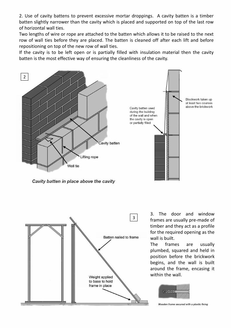
2. Use of cavity battens to prevent excessive mortar droppings. A cavity batten is a timber batten slightly narrower than the cavity which is placed and supported on top of the last row of horizontal wall ties. Two lengths of wire or rope are attached to the batten which allows it to be raised to the next row of wall ties before they are placed. The batten is cleaned off after each lift and before repositioning on top of the new row of wall ties. If the cavity is to be left open or is partially filled with insulation material then the cavity batten is the most effective way of ensuring the cleanliness of the cavity.
2
3. The door and window frames are usually pre-made of timber and they act as a profile for the required opening as the wall is built. The frames are usually plumbed, squared and held in position before the brickwork begins, and the wall is built around the frame, encasing it within the wall.
3

DOs &DON’Ts
• Do not allow mortar to collect on the tie when the wall is built, this will let water pass along the tie into the inner leaf, causing damp patches to appear on the inside of the wall.
• Wall ties should be level or slope slightly downwards towards the outer leaf of the wall with the drip positioned in the centre of the cavity and pointing downwards.
• The ends or cross joints of the brickwork should be filled solidly with mortar to prevent water penetration.
• Suitable DPC membranes should be positioned correctly, and cavity trays should be placed over lintels, and stopped ends built in to prevent water running off the ends of the trays into the cavity insulation.
• Weep holes should be formed to drain off water from cavity trays.
•
• Much better thermal insulation than a conventional masonry wall.
• Restriction of moisture passing through the wall. The wall works on the principle that water can pass through the porous outer leaf, but then collects on the inside of the outer leaf and runs down to ‘weepholes’, either at ground level or above windows, where it can escape.
• Corrosion of the wall ties if not properly protected.
• Dampness caused by careless building practice through the wall ties.
ADVANTAGES LIMITATIONS
• Care and attention must be taken when building wall ties into position, because poor workmanship may lead to damp penetration, distortion of the wall, cracking or in some cases, collapse of the wall.

TIMBER REINFORCED STONE MASONRY

This is a traditional construction system consisting of stone masonry with horizontal timber reinforcement bands. These bands (with cross pieces) act as seismic bands which prevent the walls from falling apart in an earthquake.
INTRODUCTION
STEPS OF CONSTRUCTION
FOUNDATION & PLINTH 1. Build your house on soil that is all of the same quality. Don’t place one part of the house on infill soil.
2. Foundations should be at least 2½ feet wide and 3 feet deep. 3. The plinth band should be placed 1 foot above the foundation (1 foot out of the ground). 4. The plinth band will pass under the door
5. It is better to make the first seismic band in reinforced concrete instead of wood. It will not rot. 6. Make sure that all rebars are covered all around with 1 ½’’ of concrete to avoid rusting of rebars.

7. Take care to cross the corner rebars correctly. For plinth reinforcement use two # 4 bars with # 2 bars (stirrups) every 6”.
WALLS 8. Place the wall beams every 2 feet, above the plinth band. 9. Place cross pieces at a maximum distance of 3 feet from each other.
9
8
10
12 11
10. If timber beams are too short, connect them with a long lap joint. 11. Don’t connect the beams all on the same vertical line, but spread the connection points. 12. Raise all walls together to avoid vertical joints which create weak corners.
CONNECTIONS 12. Minimum size of beam is 3” high by 4” wide. 13. Beams must be hooked together in the corners. Cut a notch of 1” into all four corner beams. Add 2 nails (3”) for more security.
14. Keep 4” of wood after all notches for strength. 15. Cross pieces help to hold the beams and walls together. You need notches only on the cross pieces, but not on the main beams.
12
13
14
15

WINDOWS AND DOORS 18. Distance between openings should be minimum 3 feet. 19. Windows and doors must not be wider than 3 feet. 20. Place the windows between the beams. 21. If you need a taller window, let the beams pass through. 22. Place cross pieces on both sides of windows and doors. 23. Don’t trim the ends of the beams to place your door. 24. For lintel add two pieces of wood in between the existing beams to support stones above. It must pass at least 1 foot into masonry on each side of the opening.
16. Where internal walls connect, only notch the internal wall beams, not the main beams. 17. Joints must be 1 foot long. For lap joints use four 3”nails to secure each joint. For Kashmiri joints, use a peg. 18. If you use a lap joint, the nails must be galvanized. They will not rust.
16 17
18
19
18
20
21
22
23 24
DOs & DON’Ts
1. The plan must have a simple form. If necessary, subdivide it into rectangular parts.
1
2
3
3. A light pitched roof is much better than a flat heavy roof.
2. The house must not be longer than 3 times its width W.
20

4. No wall must be longer than 12 feet without being connected to another wall. 5. Openings should be minimum 3 feet from corners or other opening. Windows must be smaller than 3 feet. 6. Walls must be 18 inches thick. Do not make walls thicker than 18 inch. 7. Walls must not be higher than 10 feet. 8. The timber beams act as ‘seismic bands’. The bands should be continuous and well connected.
9. Use flat or dressed stones for masonry. Don’t use round rubbles.
4
7
5 6
8
10. All walls must be connected to each other with proper stone masonry and timber beams. 11. Place through-stones every two feet. They make the wall stronger.
• Traditional Dhajji houses have proved to be
highly earthquake resistant in comparison with those made with modern building materials, have collapsed.
• Makes use of local resources instead of spending their money on costly transport of modern building materials.
ADVANTAGES LIMITATIONS • Need well-trained and skilled masons for
construction. • Water proofing and termite control a major
concern

BAMBOO SUPER-STRUCTURE

using the established supply system. It is a renewable plant with a short rotation period. The main features of a bamboo superstructure include: • Whole round bamboo columns and trussed rafters approximately every 1.2m as the main load bearing elements. • Split bamboo grids and chicken steel mesh with cement mortar plaster to provide overall stability to the structure. These elements form infill panels that are about 5 cm thick. • Bamboo mat board (BMB) gussets in combination with mild steel bolts for load bearing joints in roofing structure • Bamboo mat corrugated sheets (BMCS) as roof cladding and BMB for the walls, doors and window shutters
INTRODUCTION
STEPS OF CONSTRUCTION
1
2
3
1. Ensure firm, flat and dry site. 2. Formwork for strip footings and/or plinth course. 3. Mild steel bars attached to formwork for anchoring the wall bamboo grids.
FOUNDATIONS AND PLINTH COURSE A trench of min depth 0.5 m and min width of 0.3 m is excavated. The trench can be filled with field stones and cement grout in layers to form strip foundations underneath walls. It is recommended that the plinth course be completed also in concrete. The height of plinth should be above the flood water line or a minimum of 350 mm above ground level. Therefore formwork should be erected for the plinth course to be constructed together with the foundations. The bamboo columns should be erected in place and be embedded in the plinth course min 250 mm. The canes should be attached to the formwork to ensure vertical position during concrete casting.
Bamboo being a readily available and accessible construction material can be used in a variety of ways in the structure, walls, floor and roof. Bamboo can tolerate high values of deformations in the elastic range i.e. possesses high elasticity. Therefore bamboo houses when properly constructed are ductile i.e. being able to sway back and forth during an earthquake, without any damage to the bamboo poles. Bamboo is available in commercial quantities
The following specifications can be used: • Field stone - max size 200 mm • Grout - cement based mixed in proportion 1 : 4 (cement : sand) by volume • Bamboo columns - canes with diameter of 100mm • Concrete for plinth - mix by volume, cement : sand : aggregate : water = 1 : 3 : 3 : 1.3
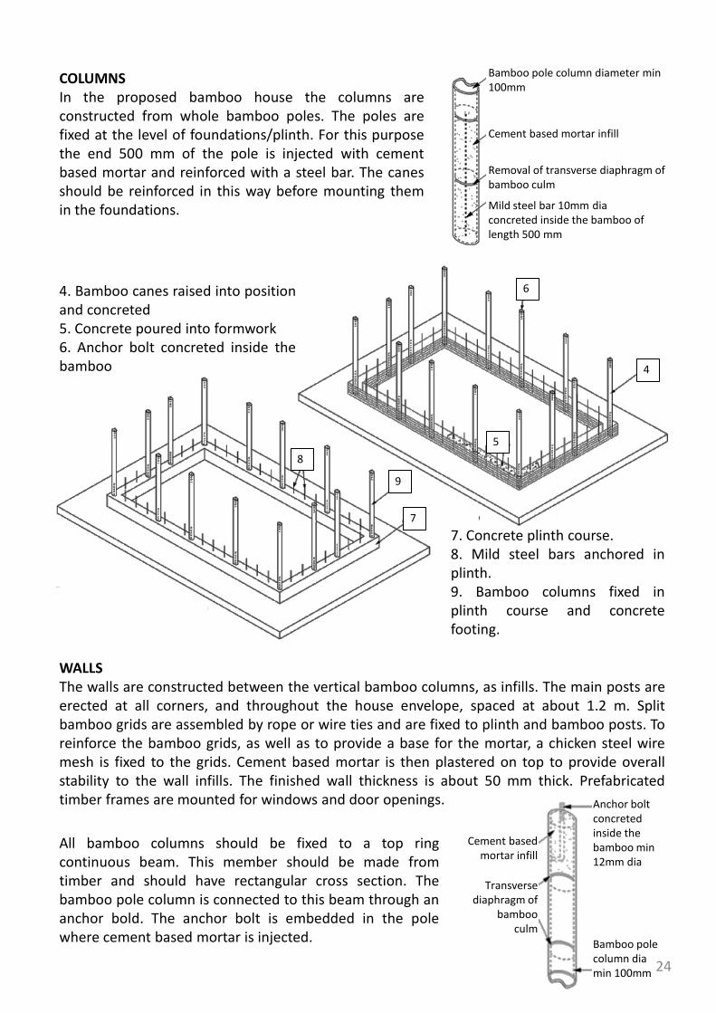
4. Bamboo canes raised into position and concreted 5. Concrete poured into formwork 6. Anchor bolt concreted inside the bamboo 4
5
6
7. Concrete plinth course. 8. Mild steel bars anchored in plinth. 9. Bamboo columns fixed in plinth course and concrete footing.
7
8
9
COLUMNS In the proposed bamboo house the columns are constructed from whole bamboo poles. The poles are fixed at the level of foundations/plinth. For this purpose the end 500 mm of the pole is injected with cement based mortar and reinforced with a steel bar. The canes should be reinforced in this way before mounting them in the foundations.
WALLS The walls are constructed between the vertical bamboo columns, as infills. The main posts are erected at all corners, and throughout the house envelope, spaced at about 1.2 m. Split bamboo grids are assembled by rope or wire ties and are fixed to plinth and bamboo posts. To reinforce the bamboo grids, as well as to provide a base for the mortar, a chicken steel wire mesh is fixed to the grids. Cement based mortar is then plastered on top to provide overall stability to the wall infills. The finished wall thickness is about 50 mm thick. Prefabricated timber frames are mounted for windows and door openings.
Bamboo pole column diameter min 100mm
Cement based mortar infill
Removal of transverse diaphragm of bamboo culm
Mild steel bar 10mm dia concreted inside the bamboo of length 500 mm
Bamboo pole column dia min 100mm
Cement based mortar infill
Transverse diaphragm of
bamboo culm
Anchor bolt concreted inside the bamboo min 12mm dia
All bamboo columns should be fixed to a top ring continuous beam. This member should be made from timber and should have rectangular cross section. The bamboo pole column is connected to this beam through an anchor bold. The anchor bolt is embedded in the pole where cement based mortar is injected.
24

21
22
10. Mild steel bars threaded to bamboo columns 11. Roof top plate (timber) 12. Mild steel anchors anchored to top plate 13. Nut screwed to anchor bolt in a recess
13
10
11
12
14. Timber frame for door 15. Horizontal split bamboo 16. Vertical split bamboo 17. Steel wire for connection of split bamboo grids
14
15
16
17
18. Chicken wire mesh attached to bamboo grids. 19. Cement based mortar on the outside. 20. Cement based mortar on the inside.
18
19
20
21. Cement based plaster on the outside 22. Cement based plaster on the inside
13
25

26 27
23. Bamboo trussed rafters 24. Bamboo mat board(BMB) gusset plates. 25. L steel clamps for column to rafter connection.
23 24
25
26. Small diameter bamboo for purlins. 27. Steel wire binding purlins to trussed rafters.
ROOF The roof should be ideally as light as possible. This would not only reduce lateral seismic loads, but would also reduce the risk of casualties in the event of roof collapse or partial collapse. Simple couple roof is adopted with bamboo trusses for rafters. The rafters are fixed to the timber top beam by means of steel clamps. Bamboo mat board (BMB) gussets, in combination with mild steel bolts, are used for the truss rafter joints. For purlins are used smaller diameter canes. Bamboo mat corrugated sheets (BMCS) are used for roof cladding. This type of roof doesn't transfer thrust onto supporting walls from gravity loading. The roof overhang of 400 mm is recommended. The main roof support structure consists of bamboo trusses. The load from the bamboo truss is transmitted to the bamboo columns through the top ring beam. The roof trusses are connected to the top ring beam by steel clamps. CONNECTION BETWEEN ROOF TRUSS AND TOP TIMBER RING BEAM
26

28. Bamboo Mat Corrugated Sheet as roof cladding 29. J bolts for cladding to purlins connection 30. Split in half bamboo pole for roof ridge.
28 29
30
ROOF CLADDING AND FINISH Bamboo mat corrugated sheets (BMCS) are used for roof cladding. The sheets are anchored to purlins by means of J bolts. BMB is used for doors and window shutters.
• Construction materials from bamboo should be treated in order to achieve longevity.
DON’Ts
DOs
• Using bamboo in foundations is not a good practice. Bamboo canes should not touch the
soil since their durability is greatly affected. • Bamboo poles should not be used for top ring beams
• The bamboo based house has a very low weight therefore foundations can be minimised.
• Basic materials for house components (bamboo, wire, bolts, chicken mesh, and cement) are inexpensive.
• Earthquake and cyclone resistant. • Only basic carpentry, masonry tools and
skills are necessary for the construction of bamboo house.
ADVANTAGES LIMITATIONS
27
• Need well-trained and skilled masons for
construction. • Water proofing and termite control a major
concern

FERRO-CEMENT CHANNEL ROOFING

Ferrocement is a type of reinforced concrete which is typically 1 to 1.5” thick and can be cast into various profiles to form pre-cast building elements. Ferrocement uses a rich cement mortar and chicken mesh reinforcement instead of conventional reinforcement bars. By casting in a semicircular profile, ferrocement channels can be made which are then used for roof construction. Ferrocement channels can be made by casting the cement-sand mortar in a mould such that it resists loads because of is profile. The circular profile carries load through its ’arch action”. The channel is then supported at its two ends which could be masonry or a beam. The roof is constructed by placing the channels side by side. Restraining Beam: An RCC restraining beam is cut at the roof level to prevent any movement of channels. This beam is very important, specially in areas which are prone to damage by natural disasters. Concrete Filling : After the channels have been placed, the valleys which are formed in between channels are filled. This is done to the joints and also to provide a smooth & level surface, to be used as a floor or terrace, if needed. The film can be done with partially concrete and partially with brickbat concrete. Alternatively, brick bat, lime concrete can also be used.
STEPS OF CONSTRUCTION
1. Prepare the support structure in masonry or framed structure before installing ferro-cement channel roof.
2 1
INTRODUCTION
2. Place the channels side by side over supporting beams or walls. Use 75 mm thick lintel band on which the channels should rest.
3. Cast 1:2 cement mortar in the gap between two channels, consolidate it and water cure for 7-10 days.
3

• Valley concrete should be laid in slope for water drainage. • The channels should be positioned properly with great care to avoid weak joints and water seepage. • Joints between two channels should be filled properly with cement concrete. • Electric wiring should be planned before laying valley concrete.
DON’Ts
DOs
• Light weight roof as compared to reinforced concrete roof. 60% deduction in dead weight. • Requires less cement and steel. Cost saving of 20%. • Shuttering, vibrator etc. not required • Simple technology which can easily be adapted by semi-skilled labour. • Quality control is easy to maintain.
• High degree of quality control and precision is required. • Due to the size of channels requires casting space, curing tank and space for air drying. • If the channels are to be transported to the site then there is a higher risk of damage if not stacked properly.
ADVANTAGES LIMITATIONS
• Do not use plank and joist in rooms > 4 meters length. • Do not just lay valley concrete for water proofing. Water proofing is not complete without a water proofing layer like bitumen etc. • Water proofing layer should not be applied before 14 days curing of valley concrete.

Materials Quantity Inner length of room = 12 feet,
inner width of room = 10 feet,
thickness of ferrocement channel = 1”,
module width of ferrocement channel = 2’9”
No. of channels = 4,
Length of channel = 14’3” including 4”
overhang at both ends
The material requirement also includes the
cement
Cement 12 bags
Coarse Sand 35 cubic feet
Aggregate 10mm 25 cubic feet
chicken mesh 25 kg
8mm MS bar 3.41 kg
binding wire 1.65 kg
welded mesh of 1"opening 11.18 kg
Labour
Skilled mason 4.00 mandays
Labour 10.00 mandays
Helper 8.00 mandays
31

FILLER SLAB

Filler slab is a variation of conventional reinforced cement concrete slab in which part of the concrete is replaced with a filler material which can be a waste material to ensure economical advantage over an RCC slab. The basic principle in a filler slab is that, considering an RCC slab of a given thickness, the concrete in the bottom half of the slab is simply dead weight and does not play a role in taking up compressive load, which is normally taken up by concrete in an RCC slab. So, this concrete can be replaced by a suitable lightweight filler material which can be accommodated in the bottom half of the slab. Since it reduces the weight of the slab by replacing concrete, savings can also be achieved in quantity of steel reinforcement without any compromise on the quality and strength of the slab. The filler materials commonly used are burnt clay tiles (such as Managalore tiles), bricks, coconut shells, terracotta pots etc.
STEPS OF CONSTRUCTION
1. Prepare the support structure in masonry or framed structure before installing ferro-cement channel roof.
2 1
INTRODUCTION
2. Place a pair of filler tiles at the centre of each rectangular space between the reinforcement steel. Check the clear cover of reinforcement (minimum 1.5cms). Lay each pair of filler tiles accurately in a line. Lay only two or three rows of tiles for convenience. If the filler material is not to be exposed, apply cement mortar over the shuttering before the filler material is placed. Other filler materials may be used as alternatives Prepare well mixed 1:2:4 cement concrete. Pour the concrete in the space between the filler materials as well as on the top
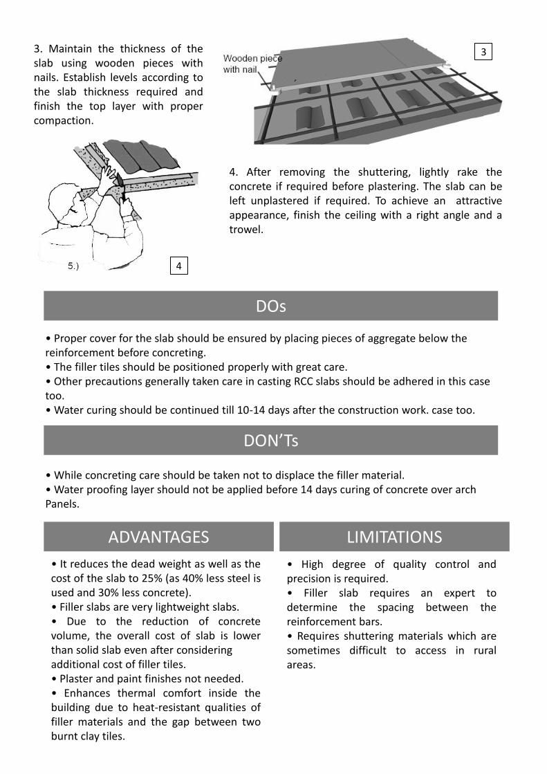
3 3. Maintain the thickness of the slab using wooden pieces with nails. Establish levels according to the slab thickness required and finish the top layer with proper compaction.
4. After removing the shuttering, lightly rake the concrete if required before plastering. The slab can be left unplastered if required. To achieve an attractive appearance, finish the ceiling with a right angle and a trowel.
• Proper cover for the slab should be ensured by placing pieces of aggregate below the reinforcement before concreting. • The filler tiles should be positioned properly with great care. • Other precautions generally taken care in casting RCC slabs should be adhered in this case too. • Water curing should be continued till 10-14 days after the construction work. case too.
• While concreting care should be taken not to displace the filler material. • Water proofing layer should not be applied before 14 days curing of concrete over arch Panels.
DON’Ts
DOs
• It reduces the dead weight as well as the cost of the slab to 25% (as 40% less steel is used and 30% less concrete). • Filler slabs are very lightweight slabs. • Due to the reduction of concrete volume, the overall cost of slab is lower than solid slab even after considering additional cost of filler tiles. • Plaster and paint finishes not needed. • Enhances thermal comfort inside the building due to heat-resistant qualities of filler materials and the gap between two burnt clay tiles.
• High degree of quality control and precision is required. • Filler slab requires an expert to determine the spacing between the reinforcement bars. • Requires shuttering materials which are sometimes difficult to access in rural areas.
ADVANTAGES LIMITATIONS
4

BAMBOO FLOORING

Bamboo flooring and bamboo board are relatively new products developed by using modern scientific methods from superior quality bamboo. Bamboo flooring is an attractive alternative to wood or laminate flooring if the bamboo has been locally sourced and also harvested in a cycle which ensures high quality of the product. Bamboo flooring tiles, being produced in India come in a plank dimension of 920 x 92 mm and thicknesses of 12, 15 and 18 mm. A tongue and groove mechanism is used to install the tiles, contributing to easy and quick installation. Bamboo flooring can be solid (made with only bamboo) or engineered (bamboo plus other woods). The benefit of engineered bamboo flooring over solid bamboo is that it uses a fraction of the surface species as compared to the solid bamboo flooring. The National Mission on Bamboo Application (NMBA) is a premier agency at the forefront of developing and standardizing new bamboo based value added products and has stabilized the bamboo flooring technology which is available for commercial production.
INTRODUCTION
STEPS OF CONSTRUCTION
1. Make sure the subfloor is dry, clean, and level. Dirty subfloors will not bond well with the adhesive, and subfloors that are not dry will eventually cause rot. If not level, the bamboo flooring will squeak when walked on. 2. Apply a moisture barrier flooring adhesive to the subfloor with a trowel. The bamboo flooring planks should be immediately placed using the tongue and groove mechanism. 4. Alternatively the bamboo flooring can be installed using a nail gun over plywood or particleboard. Once starter rows are secure, subsequent planks should be nailed directly above the tongue at a 45-degree angle to face.
• Highly durable flooring. • Hardness as high as hardwood flooring • May also be applied over radiant floor heating systems.
• Gaps in the floor may come and go seasonally or due to temperature changes.
ADVANTAGES LIMITATIONS

ECO-SAN TOILET

Ecological sanitation, or Ecosan, is a new paradigm in sanitation that recognizes human excreta and water from households not as a waste but as resources that can be recovered, treated where necessary and safely used again. Tailored to local needs, ecological sanitation systems, ideally, enable a complete recovery of nutrients in household wastewater and their reuse in agriculture. In this way, they help preserve soil fertility and safeguard long-term food security, whilst minimizing the consumption and pollution of water resources. The basic principle of the Ecosan toilet is separation of faeces and urine; separate storage of the two wastes and then application of the nutrients contained in human waste as manure and fertilizer in agriculture.
Typically, the toilet is built on a raised platform, about 1m high, to create storage space at the ground level for the waste. The faeces are stored and decomposed for a period of around 6 months and urine is diluted with water before use. The toilet has a special pan to separate the solid and liquid waste. The major challenge in the success of Ecosan is the social and habitual change which the user should be comfortable with during use of toilet and later, to recycle the nutrients.
INTRODUCTION
4
6
5

STEPS OF CONSTRUCTION
1. SITE SELECTION AND LAYOUT OF TOILET Site selection for EcoSan toilet is one of the easiest but most important steps. During selection one needs to consider the position of the emptying hole, urine container and effective use of space. It will be better at to orient the emptying hole at the backside of entrance and there should be adequate space for emptying. After selection layout is done as per the drawing.
4. SUPERSTRUCTURE OF TOILET The concrete slab will set in few days and then construction of superstructure of toilet can be started. The superstructure is similar to an ordinary toilet. After a complete setting of the concrete slab, i.e. in 2 to 3 weeks , formwork for the slab is removed. 5. PLUMBING WORK Final work of toilet is plumbing i.e. urine container, vent pipe, black water pipe etc fitting works. Plumber must be careful to control leakage.
2. EXCAVATION, BRICK WORK IN FOUNDATION AND PCC WORK Excavation is done for wall foundation. 12" inches wide and 18" depth trench is excavated for foundation wall. Then dry brick soling is done and brickwork for wall is started. The wall should rise up to 6" above existing ground level to insure flooding of water into the vault during rain. 4 inch thick platform is prepared with PCC. 3. BRICK WORK FOR CHAMBER After setting of platform brick work for chamber is started. Typically 4" brick wall is preferred for chamber construction. Chamber is divided into two vaults by a 4" wall partition. Height of chamber is generally 2 feet. Upon completion of wall construction internal face of wall is plastered and punning is done to reduce possibility of water seepage. Finally concreting of slab is cast over the chamber with pan. Pipe to convey urine and anal wash water is concealed in slab where as Tee for the vent pipe is fitted just under the slab. Pipe fitting work is more sensitive and it requires proper care to ensure that the pipe does not move during the casting of the slab. Otherwise it makes leakage of into the chamber and creates more difficulties to maintain.

• Eco san toilets structure should be constructed above ground level. • The base should be cemented and made impervious. • Vent pipe should be provided at the junction of the separation walls of the two composting chambers to remove air and gas in the chambers. • The vent pipe should be of adequate size and provide with fly net at the top. • The holes in RCC slab should be made with 9” and 4” pipes at the time of casting of slab only.
• The structure should be made over a pit of given size only. Do not build the superstructure without casting the cement bed and proper curing of the same. • Do not make the RCC slab without proper formwork. • Pipes should not be fixed after the squatting slab is cast. • Do not leave the processing chambers without proper sloping and waterproofing as water should not enter these chambers. • Do not leave the chamber open as it can lead to health hazards and improper composting.
DON’Ts
DOs
6. SOAK PIT OR CONSTRUCTED WETLAND FOR BLACK WATER Generally at the side of urine container a soak pit or constructed wetland for the waste water is constructed. The pit should be 12 inches deep and filled with layer of aggregate or brick ballets in bottom and coarse sand layer at the top.
• It increases soil fertility as the waste is used as fertilizer and prevents water contamination. • It doesn’t require any flushing mechanism. • It reuses the human waste. • Useful for water logged and high water table areas. • Improves rural and community hygiene.
• High degree of quality control and hygiene. • Skilled masons are required for buiding eco san toilets. • Construction is more costly than regular toilets. • It needs education for usage and acceptance of people. • It has continuous use of ash.
ADVANTAGES DISADVANTAGES

41
