above ground pipeline design
TRANSCRIPT

8/2/2019 Above Ground Pipeline Design
http://slidepdf.com/reader/full/above-ground-pipeline-design 1/15
Above ground pipeline design
1.0 Introduction.
Application engineering involves designing a fiberglass piping system to ensure thesuccessful installation. It considers the specific service conditions, thorough engineeringanalysis, and selection of the specific fiberglass piping system to meet the service conditions.The total process involves the application of engineering skills and product knowledge to achievethe desired overall performance.
1.0.1 Test methods and physical properties. The ultimate and allowable designstresses and physical properties for fiberglass pipe are arrived at from standardized testmethodologies and some use modified techniques of standardized test methods. Theseproperties evolve around the minimum reinforced wall thicknesses. These properties can befound in the Conley Product Data and Engineering Guide.
1.0.2 Internal pressure rating. The hydraulic design basis for internal pressure ratingof fiberglass piping comes from a long-term test performed in accordance with ASTM D 2992.The hydraulic design basis is the hoop stress (or strain) that provides an estimated life of 100,000hours for static pressure applications.
1.0.3 Thermal expansion and contraction. Fiberglass pipe has a thermal expansionrate in the axial direction about twice that of steel pipe. The total expansion or contraction for apiping system is determined by the following equation:
Lc = 12 Ct L Tc (Eq. 1)
Where:Lc = Length change, inches
Ct = Coefficient of thermal expansion, in/in/ °FL = Length of line between anchors, feet
Tc = Temperature change, °F(Maximum operating temperature minus installation temperature for expansion.Installation temperature minus minimum operating temperature for contraction.)
Example 1: Find the change in length per linear foot of pipeline for a 2-in. nominal pipe size with
a temperature change of 60°F and coefficient of expansion of 9.5 x 10⁻⁶
.
Lc = 12 (9.5 x 10⁻⁶) (1) (60) = 0.0068 in./ft.
To determine the effects of thermal expansion and contraction on a piping system, one shouldknow:
1. The design temperature conditions.2. The size and physical properties of the pipe.3. The layout of the system, including dimensions and the thermal movement, if any, of
the terminal points.4. The limitations on end reactions.

8/2/2019 Above Ground Pipeline Design
http://slidepdf.com/reader/full/above-ground-pipeline-design 2/15
Conley Corporation/Tulsa, Oklahoma
2
1.1 Thermal expansion design.
1.1.1 Introduction. Above ground installations describe pipelines installed on top of thesoil (above or at grade) or suspended in the air in some fashion. In the design of above groundpipelines, the supporting and guiding of the pipe become important considerations because ofthermal expansion.
In addition to pressure resistance and life limitations, one should consider the effects of
thermal expansion and contraction. A number of methods accommodate the length changesassociated with thermal expansion and contraction. Three most commonly used methodsinclude:
• Restricted end loadings (1.2)
• Guide spacing (1.3)
• Direction changes (1.6)
Two other methods that are seldom used and not normally recommended are:
• Expansion loops (1.5)
• Mechanical expansion joints (1.4)
Guides, expansion loops and mechanical expansion joints are installed in straight lineswhich are anchored at each end. Experience has shown that direction changes are the leastexpensive method of accommodating thermal expansion. Guide spacing is the next mosteconomical method, followed by mechanical expansion joints.
For small temperature changes, and piping systems which consist of short run lengths, itis usually unnecessary to make special provisions for thermal expansion. However, any systemshould have the capability to accommodate length changes. The methodology of directionchanges in Section 1.6 solves this design criterion.
Experience has shown that above ground piping systems require anchors. Theseanchors limit pipe movement due to vibrations and transient loading conditions. Anchors alsofasten all transition points within the system. Transition points are places where pipe diameter,material, elevation or direction changes, or manufacturer changes. Anchors at transition pointslimit the transfer of thermal end loads from line section to line section.
1.2 Thermal end loads.
The axial modulus of elasticity of most fiberglass pipe is about 3.3-4.0% that of steel pipe.This relatively low modulus is an advantage that becomes apparent during the design phase.One benefit from the low modulus comes with guides to handle thermal expansion. Lower endloads mean that restraining equipment need not be as heavy as that for steel piping.
Some length change can result from internal pressures in the piping system. Experiencehas shown that this elongation is insignificant and need not be considered in the design. See theAnchor Loads Due to Restrained Thermal Expansion Table found in the Conley Product Dataand Engineering Guide.
The equation for calculating the thermal end load is:
EL = Ct E A Tc (Eq. 2)

8/2/2019 Above Ground Pipeline Design
http://slidepdf.com/reader/full/above-ground-pipeline-design 3/15
Conley Corporation/Tulsa, Oklahoma
3
Where:EL = Thermal end load, lb.
Ct = Coefficient of thermal expansion, in/in/ °FE = Modulus of elasticity, psi (Compressive for expansion and tensile for contraction)A = Cross sectional area, in.
2
Tc = Temperature change, °F(Maximum operating temperature minus installation temperature for expansion.Installation temperature minus minimum operating temperature for contraction.)
Example 2: For the 2-in. nominal pipe in Example 1, with a reinforced OD of 2.375-in. (minimum)and a maximum reinforced ID (d) of 2.35-in., the compressive modulus of elasticity, (E L) is 1.3 x
106
psi, and the tensile modulus of elasticity is 1.72 x 10⁶
psi. The pipeline is installed at 75°F
and has a maximum operating temperature of 200°F and a minimum operating temperature of
35°F. The coefficient of thermal expansion is 9.5 x 10⁻⁶
.
Step 1 Calculate the temperature changes:
Tc = 200 – 75 = 125°F (for expansion)
Tc = 75 – 75 = 40°F (for contraction)
Step 2 Calculate the cross sectional area:
A = π /4 (OD2
– ID2)
A = 0.7854 (2.3752
– 2.2352) = 0.507 in.
2
Design calculations use only the reinforced dimensions. Resin rich surfaces do not
contribute significantly to the strength of the pipe.
Step 3 Calculate the end load using Eq.2:
EL = (9.5 x 10⁻⁶
) (1.3 x 10⁶) (0.507) (125) = 898 lb. (for expansion)
EL = (9.5 x 10⁻⁶
) (1.72 x 10⁶) (0.507) (40) = 380 lb. (for contraction)
When pipe lengths between anchors expand, the pipe undergoes compression. When
contraction occurs, the pipe experiences tension.
1.2.1 Restrained End Loading. The most efficient method of handling thermalexpansion in Conley Piping Systems is restrained End Loading. This is simply anchoring eachend of long straight runs of pipe and guiding to prevent buckling. This method eliminates theneed for expansion loops and expansion joints and results in a much more stable system. It alsoeliminates movement in the line and prevents excessive bending stresses on branching fittingssuch as Tee’s and Laterals.
The decision to use restrained end loading is based primarily on pipe length andtemperature differences. As a rule, straight runs of about 100-ft usually require an anchor at eachend if there is enough temperature difference between installation and operating temperature.Short straight runs that end in natural offsets or loops use anchors often enough to stabilize thepiping but allow it to grow as necessary. Also as a general rule, guides should be located at
every other support point. For runs longer than 100-ft, or temperature changes greater than 100degrees F. use mid-point anchors about every 200-ft and guide at every support.
Example 3: For a run of 250-ft, use end anchors and one mid-point anchor. For a run of 400-ft,use end anchors and one mid-point anchor. For a run of 600-ft, use end anchors and one at 200ft and one at 400-ft.
8/2/2019 Above Ground Pipeline Design
http://slidepdf.com/reader/full/above-ground-pipeline-design 4/15
Conley Corporation/Tulsa, Oklahoma
4
Here is a brief example of restrained end loading design calculations:
In the case of 3-in pipe, having a reinforced thickness of 0.15-in, the cross sectional area is about1.5 sq. in. Assuming an installation temperature of 0 degrees and operating temperature of 180degrees, the Delta T is 180 degrees F. This results in a compressive load of 7220 lb. Thecompressive stress is 4813 psi compared to an ultimate of 22,720 psi (not reported in the ConleyCatalog). This results in a safety factor of 4.7. The actual load would of course be considerablyless since the installation temperature will be much higher.
When the restrained pipe cools to a point below the installation temperature it goes intotension. The ultimate tensile stress of filament wound pipe is approximately 30,000 psi so itwould take a very large temperature drop in the pipe to generate that kind of load.
With the required Anchors, guides and supports installed according to the design, the“restrained end loading” method of piping design is the simplest and most cost effective designfor fiberglass piping systems.
1.3 Guide spacing.
Installing anchors at all directional and elevation changes serves to divide the pipingsystem into straight runs. With anchors installed, guides prove to be an economical method fordealing with expansion. The relatively low modulus of fiberglass pipe allows it to absorb the
thermal stresses as compressive stresses in the pipe wall. Compressive stresses fromexpansion may result in buckling unless the pipe is constrained at close intervals to preventcolumnar instability.
See the maximum Guide Spacing Table for different changes in temperature found in theConley Product Data and Engineering Guide.
Compare guide spacing intervals with the intervals for supports. Then adjust the guidespacing for a better match with the support spacing. For example, one might adjust the spacingso a guide replaces every second or third support. Guides are essentially modified supports.
Remember, all guides act as supports and must meet the minimum requirements forsupports, anchors, and guides as prescribed in Paragraph 1.7.
1.4 Expansion joint design.
Expansion joints are seldom used and normally not recommended for fiberglass pipingsystems. Expansion joints can help relieve long straight pipe runs. Various types of expansion
joints are available and suitable for use with fiberglass piping systems. Since the forcesdeveloped during a temperature change are relatively low, compared with steel piping systems, itis essential to specify an expansion joint design which activates with low force. Remember thatfiberglass pipe runs expand more than most steel piping systems. The required movement perexpansion joint, and the number of expansion joints may be greater for fiberglass piping systems.
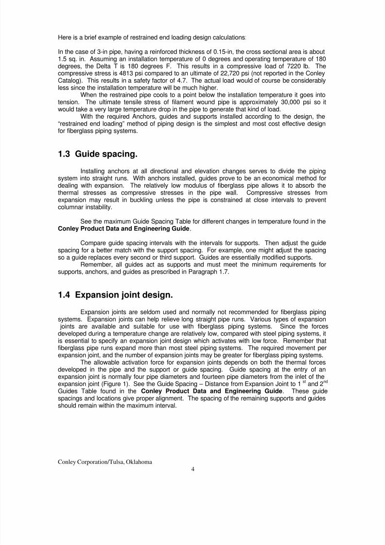
The allowable activation force for expansion joints depends on both the thermal forcesdeveloped in the pipe and the support or guide spacing. Guide spacing at the entry of anexpansion joint is normally four pipe diameters and fourteen pipe diameters from the inlet of the
expansion joint (Figure 1). See the Guide Spacing – Distance from Expansion Joint to 1st and 2nd Guides Table found in the Conley Product Data and Engineering Guide. These guidespacings and locations give proper alignment. The spacing of the remaining supports and guidesshould remain within the maximum interval.
8/2/2019 Above Ground Pipeline Design
http://slidepdf.com/reader/full/above-ground-pipeline-design 5/15
Figure 1Typical expansion joint installation
The equation for calculating the allowable activation force is:
Pcr = π2
Ec I/ LG2
(Eq. 3)
Where:Pcr = Critical buckling force of pipe, lb.Ec = Compressive modulus of eleasticity, psiI = Moment of inertia, in.
4
LG = Support spacing interval, in. (From Tables)
Example 4: Compute the critical buckling force for the 2-in. nominal pipe:
Pcr = 3.14162
(1.3 x 10⁶) (0.337)/[(7.5) (12)]
2
Pcr = 534 lb.
Note: For large diameter piping, the pressure thrust must be considered. Pressure thrustis the design pressure times the area of the expansion joint.
In all applications, the activation force of the expansion joint must not exceed the thermalend loads developed by the pipe. The cost and limited motion capability of expansion jointsmakes them impractical to use in many applications. In these cases, loops, guide spacing, orshort lengths of flexible hose can handle thermal expansion. The expansion joint needs ananchor on one side for proper operation.
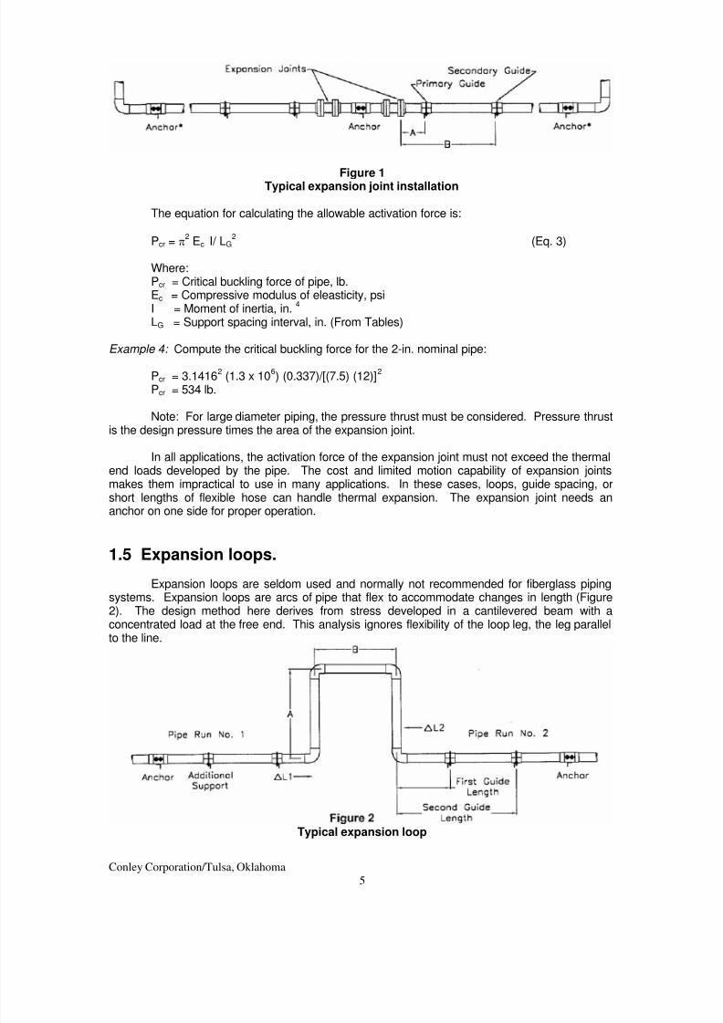
1.5 Expansion loops.
Expansion loops are seldom used and normally not recommended for fiberglass pipingsystems. Expansion loops are arcs of pipe that flex to accommodate changes in length (Figure2). The design method here derives from stress developed in a cantilevered beam with aconcentrated load at the free end. This analysis ignores flexibility of the loop leg, the leg parallelto the line.
Typical expansion loop
Conley Corporation/Tulsa, Oklahoma
5

8/2/2019 Above Ground Pipeline Design
http://slidepdf.com/reader/full/above-ground-pipeline-design 6/15
Conley Corporation/Tulsa, Oklahoma
6
Two guides on both sides of each expansion loop ensure proper alignment. Therecommended guide spacing is four and fourteen nominal pipe diameters, the same as forexpansion joints in Paragraph 1.4. Additional guides or supports should be located so maximumspacing interval is not exceeded.
See the Loop Leg Length Table and calculations found in the Conley Product Data andEngineering Guide.
1.6 Directional changes.
In some installations, system directional changes can perform the same function asexpansion loops. Directional changes involving some types of fittings, such as saddles, shouldnot be used to absorb expansion or contraction. The bending stresses may cause fitting failure.
Stress in the pipe at a given directional change depends on the total change in length toabsorb and the distance to the first secure hanger or guide past the directional change. In otherwords, flexible leg length is based on the maximum change in length.
Recommended support or guide spacing cannot be disregarded. However, flexible, ormovable supports, such as strap hangers, can provide support while allowing the pipe to moveand absorb the changes in length. Supports must prevent lateral movement or pipe buckling.
On some designs, one expects large thermal movements at a change in direction. A
short length of flexible hose installed here will absorb some of the line movement. This method ofhandling thermal expansion is usually the most economical means of compensating for largedisplacements when the guide spacing method cannot be used. Manufacturers provide hosespecification sheets giving the minimum bend radius, chemical compatibility, temperature andpressure rating of a particular flexible hose. These product sheets help guide particularapplications.
1.7 Supports, anchors and guides.
Six basic rules control design and positioning for supports, anchors, and guides.
Rule #1. Avoid line contact and point loads.Rule #2. Meet minimum support dimensions.
Standard pipe supports designed for steel pipe can support fiberglass pipe. Exercisecare so the minimum support width is provided. See the Recommended Minimum Hanger Clamp(support clamp) Width Table found in the Conley Product Data and Engineering Guide.Supports failing to meet the minimum widths must be augmented with a protective sleeve of splitfiberglass pipe or metal. In all cases the support must be wide enough so the bearing stressdoes not exceed 85 psi.
Sleeves augmenting support widths must be bonded in place using adhesives stable atthe system’s maximum operating temperature. All pipe and sleeve bonding surfaces must beprepared by sanding the contacting surfaces.
Rule #3 Protect against abrasion.
Provide adequate protection in areas where possible mechanical damage could occur. Ifvibrations, or pulsations, are possible, protect contacting surfaces from wear (Figure 3).

8/2/2019 Above Ground Pipeline Design
http://slidepdf.com/reader/full/above-ground-pipeline-design 7/15
Figure 3 Figure 4
Rule #4 Support heavy equipment independently.Valves, and other heavy equipment, must be supported independently in both horizontal
and vertical directions (Figure 4).
Rule #5 Avoid excessive bending.When laying pipe lines directly on the surface, take care to ensure there are no excessive
bends that would impose undue stress on the pipe.
Rule #6 Avoid excessive loading in vertical runs.
Support vertical pipe runs as shown in Figure 5. The preferred method is to design for“pipe in compression”. If the “pipe in tension” method cannot be avoided, take care to limit thetensile loadings below the recommended maximum tensile rating of the pipe. Install guide collarsusing the same spacing intervals used for horizontal lines (Figure 5).
Figure 5
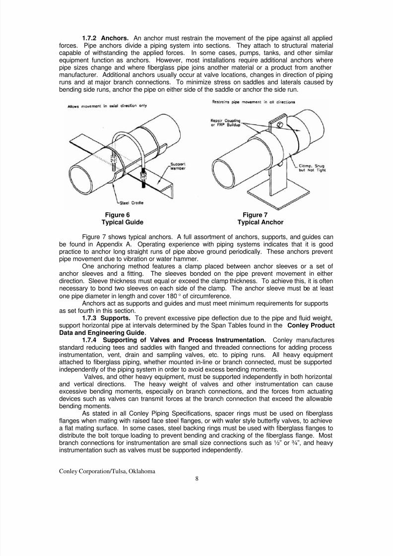
1.7.1 Guides. The guiding mechanism must be loose to allow free axial movement ofthe pipe. However, the guides must be attached rigidly to the supporting structure so the pipe
moves only in the axial direction (Figure 6).All guides act as supports and must meet the minimum requirements for supports,
anchors, and guides presented in Section 1.7.When frequent thermal cycles, vibration, or pulsating loadings affect the pipe, it needs
protection at all contact points. This is normally accomplished by bonding to the pipe wall a wearsaddle made of steel or one-half of a section of the same pipe or coupling.
Conley Corporation/Tulsa, Oklahoma
7
8/2/2019 Above Ground Pipeline Design
http://slidepdf.com/reader/full/above-ground-pipeline-design 8/15
1.7.2 Anchors. An anchor must restrain the movement of the pipe against all appliedforces. Pipe anchors divide a piping system into sections. They attach to structural materialcapable of withstanding the applied forces. In some cases, pumps, tanks, and other similarequipment function as anchors. However, most installations require additional anchors wherepipe sizes change and where fiberglass pipe joins another material or a product from anothermanufacturer. Additional anchors usually occur at valve locations, changes in direction of pipingruns and at major branch connections. To minimize stress on saddles and laterals caused bybending side runs, anchor the pipe on either side of the saddle or anchor the side run.
Figure 6 Figure 7Typical Guide Typical Anchor
Figure 7 shows typical anchors. A full assortment of anchors, supports, and guides canbe found in Appendix A. Operating experience with piping systems indicates that it is goodpractice to anchor long straight runs of pipe above ground periodically. These anchors preventpipe movement due to vibration or water hammer.
One anchoring method features a clamp placed between anchor sleeves or a set ofanchor sleeves and a fitting. The sleeves bonded on the pipe prevent movement in eitherdirection. Sleeve thickness must equal or exceed the clamp thickness. To achieve this, it is oftennecessary to bond two sleeves on each side of the clamp. The anchor sleeve must be at least
one pipe diameter in length and cover 180° of circumference.Anchors act as supports and guides and must meet minimum requirements for supports
as set fourth in this section.1.7.3 Supports. To prevent excessive pipe deflection due to the pipe and fluid weight,
support horizontal pipe at intervals determined by the Span Tables found in the Conley ProductData and Engineering Guide.
1.7.4 Supporting of Valves and Process Instrumentation. Conley manufacturesstandard reducing tees and saddles with flanged and threaded connections for adding processinstrumentation, vent, drain and sampling valves, etc. to piping runs. All heavy equipmentattached to fiberglass piping, whether mounted in-line or branch connected, must be supportedindependently of the piping system in order to avoid excess bending moments.
Valves, and other heavy equipment, must be supported independently in both horizontaland vertical directions. The heavy weight of valves and other instrumentation can cause
excessive bending moments, especially on branch connections, and the forces from actuatingdevices such as valves can transmit forces at the branch connection that exceed the allowablebending moments.
As stated in all Conley Piping Specifications, spacer rings must be used on fiberglassflanges when mating with raised face steel flanges, or with wafer style butterfly valves, to achievea flat mating surface. In some cases, steel backing rings must be used with fiberglass flanges todistribute the bolt torque loading to prevent bending and cracking of the fiberglass flange. Mostbranch connections for instrumentation are small size connections such as ½” or ¾”, and heavyinstrumentation such as valves must be supported independently.
Conley Corporation/Tulsa, Oklahoma
8
8/2/2019 Above Ground Pipeline Design
http://slidepdf.com/reader/full/above-ground-pipeline-design 9/15
Conley Corporation/Tulsa, Oklahoma
9
Supports can be attached directly to valves and other instrumentation and connected tostructural steel or floor type supports. In some cases where the valve or instrumentation cannotbe easily supported, supports can be provided for the flange or piping immediately adjacent to thevalve or instrument.
1.8 Bending.
The minimum bending radius for fiberglass pipe normally results from a design stress thatis one eighth of the ultimate short term bending stress. Certain fittings, such as saddles andlaterals, are more susceptible to bending failure than other types. See the Minimum Bend RadiusTables found in the Conley Product Data and Engineering Guide.
1.9 Thermal conductivity.
The thermal conductivity of the glass resin laminate in a fiberglass pipe wall isapproximately 1% that of steel. However, in most heat transfer situations the heat loss or gain forpipe is controlled by the resistance to heat flow into the surrounding media (i.e. air or soil) ratherthan the thermal conductivity of the pipe. This reduces the insulating effect of the relatively thin
fiberglass pipe wall. For this reason, thermal insulating tables for steel pipe can be used to sizethe insulation for most fiberglass pipelines.
The coefficient of thermal conductivity for all Conley Piping Systems is 9.5 x 10⁻⁶
BTU/hr
ft2 °F/in. The K factor is 7.9 x 10
-7BTU/hr ft
2 °F
1.10 Heat tracing.
Both steam tracing and electrical heating tapes are acceptable techniques for heatingfiberglass pipe. When using either method, three criteria govern the maximum elementtemperature.
1. The average wall temperature must not exceed the temperature rating of the pipe.
2. The maximum tracing temperature must not be more than 25°F above the maximumrated temperature of the pipe.
3. The maximum recommended chemical resistance temperature of the pipe must not beexceeded at the inside wall of the pipe.
Application of these three limits is best explained by example:
Example 5: What is the maximum heat tracing temperature allowed to maintain a 50% caustic
solution at 95°F inside a fiberglass pipe with a 210°F maximum service temperature. The
published resistance temperature for this application is 100°F.
Step 1 For Criteria 1, the following equation is applicable:
At = (Ti + Tt)/2 (Eq. 4)

8/2/2019 Above Ground Pipeline Design
http://slidepdf.com/reader/full/above-ground-pipeline-design 10/15
Conley Corporation/Tulsa, Oklahoma
10
Where:
At = Average wall temperature, °F
Ti = Inside wall temperature, °F
Tt = Heat tracing temperature, °F
At = (95 + Tt)/2 = 210°F
Tt = 325°F
Step 2 For Criteria 2, the following equation is used:
Tt = TR + 25 (Eq. 5)
Where:
TR = Maximum rated temperature of pipe, °F
Tt = 210 + 25 = 235°F
Step 3 The maximum tracing element temperature is the lesser of the values calculated
using Eqs. 4 and 5. In this case the value is 235°F.
The maximum tracing element temperature using this methodology applies only to
applications involving flowing, non-stagnant, fluid conditions. For stagnant conditions, themaximum allowable trace element temperature is the chemical resistance temperature of the
pipe. For this example Tt < 100°F.
Step 4 For Criteria 3, it is necessary to check the manufacturer’s published data todetermine recommended chemical resistance of the pipe for this application. This value iscompared with the inside wall temperature, Ti. The published value must be greater than Ti.
For Example 5 then the maximum allowable trace temperature is then 100°F.
1.11 Limitations.
The limitations and design values for fiberglass pipe are different from those normallyused for steel pipes. The following outline presents various considerations and limitations thatdiffer somewhat from those used with steel product. Most design pressures or stresses are 25%of ultimate failure pressure or stress. Exceptions are internal pressure and bending stress asnoted below.
1.11.1 Design pressure or stress. Design stresses for pipe internal pressure comefrom ASTM D 2992. The internal operating pressure for fittings generally are based on one thirdof the ultimate short term failure pressure (ASTM D 1599). These values typically become thedesign allowables for the pipe.
1.11.2 Modulus of elasticity. There is more than one modulus of elasticity forfiberglass pipe because the end product is an anisotropic composite material. The tensile,bending and compressive moduli differ significantly and one should take care to use the correctvalue. Precise values for the moduli for specific conditions of loading should come from themanufacturer.
1.11.3 Allowable tensile or compressive loads. Typically the allowable design stressis 25% of the ultimate short term failure loads. These stress values can be used with theminimum reinforced wall thickness (area) to calculate the allowable maximum loads.
1.11.4 Bending loads. Ultimate beam stress is determined by using a simple beam witha concentrated load applied to the center to achieve short term failure. The allowable designstress is then established by apllication of an 6:1 factor of safety to the ultimate failure value. The6:1 factor is selected to compensate for combined loading which occurs in piping applications.
8/2/2019 Above Ground Pipeline Design
http://slidepdf.com/reader/full/above-ground-pipeline-design 11/15
Conley Corporation/Tulsa, Oklahoma
11
1.12 Vacuum or external pressure.
Fiberglass pipe can convey materials under vacuum, laid on the bottom of rivers or lakes,or otherwise used so external pressures will tend to collapse the pipe. The ability of fiberglasspipe to resist collapse pressure depends on the pipe size and ratio of diameter to wall thickness.The manufacturer’s recommended values should be used for design purposes.
Excerpts from Stringfellow, William D. ed. Fiberglass Pipe Handbook. Fiberglass Pipe Institute.Second edition 1992. Chapter 6.

8/2/2019 Above Ground Pipeline Design
http://slidepdf.com/reader/full/above-ground-pipeline-design 12/15
Conley Corporation/Tulsa, Oklahoma
12

8/2/2019 Above Ground Pipeline Design
http://slidepdf.com/reader/full/above-ground-pipeline-design 13/15
Conley Corporation/Tulsa, Oklahoma
13

8/2/2019 Above Ground Pipeline Design
http://slidepdf.com/reader/full/above-ground-pipeline-design 14/15
Conley Corporation/Tulsa, Oklahoma
14

8/2/2019 Above Ground Pipeline Design
http://slidepdf.com/reader/full/above-ground-pipeline-design 15/15
Conley Corporation2795 East 91st Street
Tulsa, Oklahoma 74137
www.conleyfrp.com
800.331.5502
15