abs brakes-teves mkii
TRANSCRIPT

1
Mark II Anti-Lock Brakes
Contents
Overview 2 – 5
System Description 6 – 7
System Operation 8 – 15
Components 16 – 23
Diagnostic Trouble Codes (Blink Codes) 24
The DTC Summary for this section follows at the end of the section.

2
Mark II Anti-Lock Brakes
Overview
The Teves MK II brake system combines normal system operation, hydraulic power boost andanti-lock braking. The system uses an independent electrically-driven motor / pump unit to pro-vide both boost pressure and brake application pressure. A common operating fluid, DOT 4BRAKE FLUID, is used for both power boost and brake application.
In this system, three hydraulic circuits are used — one to each front wheel and one to the rearwheels. Depending on the mode of operation, the circuits operate differently:
Normal Operation
The two front hydraulic circuits operate conventionally via the master cylinder, assisted by thehydraulic booster. The rear hydraulic circuit is operated continuously by the controlled pressurein the booster via the pressure reducing valve. Simply stated, during normal operation, the fronthydraulic circuits are “static” and the rear circuit “dynamic.”
Anti-lock Operation
When anti-lock control is required, the front hydraulic circuits also become “dynamic” as boostpressure replaces master cylinder pressure via the main valve.
The four wheel speed sensors input to the ABS control module (ABS CM), which processes theinformation and modulates the three sets of solenoid valves in the valve block to control thepressure in the three circuits and prevent wheel lock. Because both rear wheels share a com-mon circuit, a tendency for one wheel to lock will result in control of both wheels according tothe need of the “locking” wheel.
The state of the anti-lock braking system is continuously monitored by the ABS CM. If a systemfault is detected, the CM flags a diagnostic trouble code (DTC) corresponding to the fault , acti-vates the ANTI LOCK MIL, stores the DTC in its nonvolatile memory and signals the instrumentpack vehicle condition monitor (VCM). For most faults the CM will also switch the system OFFuntil the fault is corrected.
Full boosted braking to all wheels is maintained if the control module switches off the ABS sys-tem. If a failure of the hydraulic boost portion of the system occurs, the brake system willfunction on the front wheels only, without boost pressure.
MK II ABS ENGINE COMPARTMENT COMPONENTS: SEDAN RANGE 1993 – 1994 MY
HYDRAULICACTUATION UNIT
T500/2.01
MOTOR / PUMPUNIT

3
Mark II Anti-Lock Brakes
Fault Diagnostics
In addition to JDS and PDU diagnostics accessed through the dedicated ABS diagnostic connec-tor, located near the CM, the TEVES MK II anti-lock braking system incorporates a facility thatallows the numeric DTCs to be displayed as coded blinks on the ABS MIL.
Refer to page 24 for instructions for activating the “blink code” display.
MK II ABS SYSTEM: SEDAN RANGE 1990 – 1992 MY
MOTOR / PUMPUNIT
HYDRAULICACTUATION UNIT
FRONT WHEEL SPEED SENSORS
PRESSURE REDUCING VALVE
ABS CONTROLMODULE
T500/2.02
MK II ABS SYSTEM: XJS RANGE UP TO 1995 MY VIN 198335 (INBOARD REAR BRAKES SHOWN)
MAINVALVE
ACCUMULATOR
MOTOR / PUMPUNIT
COMBINED PRESSURESWITCH
FRONT WHEELSPEED SENSORS
SOLENOID VALVEBLOCK
PRESSUREREDUCING VALVE
ABS CONTROLMODULE
REAR WHEELSPEED SENSORS
HYDRAULICACTUATOR
RESERVOIR
T500/2.03

4
Mark II Anti-Lock Brakes
Overview (continued)
Sedan Range: 1990 – 1992 MY
In the Sedan Range from model years 1990 – 92, the motor / pump unit, reservoir and hydraulicactuation unit are integrated on the brake pedal and accelerator housing. The motor / pump unitcontains the hydraulic pump, motor, accumulator and combined pressure switch. The hydraulicactuator incorporates many components including the solenoid valve block.
NOTES
ABS MOTOR / PUMP UNIT, RESERVOIR AND HYDRAULIC ACTUATION UNIT: SEDAN RANGE 1990 – 1992 MY
ACCUMULATORRESERVOIR
HYDRAULICACTUATION UNIT
SOLENOID VALVEBLOCK
MOTOR / PUMPUNIT
COMBINEDPRESSURE SWITCH
T500/2.04

5
Mark II Anti-Lock Brakes
Sedan Range: 1993 – 1994 and XJS Range: 1989 – 1995 MY
In all XJS Range models and 1993 – 94 Sedan Range models, the motor / pump unit is locatedseparately on the right side of the firewall. The reservoir and the hydraulic actuation unit are inte-grated on the brake pedal and accelerator housing. The motor / pump unit contains the hydraulicpump, motor, accumulator and combined pressure switch. The hydraulic actuator incorporatesmany components including the solenoid valve block.
NOTES
ACCUMULATOR
RESERVOIR
HYDRAULICACTUATION UNIT
SOLENOID VALVEBLOCK
MOTOR / PUMPUNIT
COMBINEDPRESSURE SWITCH
ABS MOTOR / PUMP UNIT, RESERVOIR AND HYDRAULIC ACTUATION UNIT: SEDAN RANGE 1993 – 1994 MYAND XJS RANGE UP TO 1995 MY VIN 198335
T500/2.05

6
Mark II Anti-Lock Brakes
System Description
Hydraulic Actuation Unit
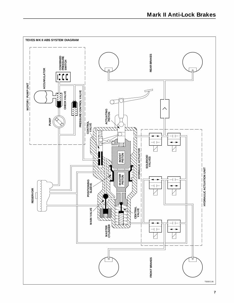
The hydraulic actuation unit contains the reservoir and the components used for pressure appli-cation, boost application and anti-lock valving.
Actuating piston
The actuating piston transmits the motion from the brake pedal to the control valve and the boost piston.
Control valve
The control valve opens and closes the high pressure line from the accumulator to the actuatorhydraulic booster.
Hydraulic booster
The boost piston is independent from the actuating piston and applies boost pressure on themaster cylinder piston. Boost pressure is used to directly operate the rear brakes.
Master cylinder
The master cylinder operates the front brakes only.
Main valve
The solenoid-activated main valve is opened under anti-lock conditions to apply boost pressuredirectly to the master cylinder and the front brake circuits.
Central valve
The central valve opens under anti-lock conditions to allow boost pressure to be applied directlyto the front brakes.
Positioning sleeve
The positioning sleeve is used during anti-lock operation to minimize brake pedal pulsation.
Solenoid valves
The six solenoid valves direct hydraulic pressure and hydraulic return in the three brake circuitsduring anti-lock conditions. During normal operation, the valves are at rest, allowing conventionalapplication.
Motor / Pump Unit
The motor / pump unit supplies the system-operating hydraulic pressure.
Pump
The pump is driven by an electric motor and is switched on and off to maintain a range of oper-ating pressure.
Accumulator
The accumulator stores the pump pressure and provides reserve for normal, anti-lock and pumpfailure operations. A check valve prevents pressure loss.
Pressure control valve
The pressure control valve limits the maximum system pressure to 210 bar (3046 psi).
Combined pressure switch
Two sets of contacts in the pressure-operated switch signal the ABS control module for activa-tion of warnings and anti-lock shutdown. The other contacts switch the pump on and off. (Thebrake warning switch contacts close at 105 bar [1255 psi] turning on the warning light. The pumpswitches on at approximately 140 bar [2030 psi] and off at approximately 180 bar [2610 psi].)
Pressure Reducing Valve
Because the rear brakes operate directly off boost pressure, a pressure-limiting device is neces-sary. The pressure reducing valve is located in the rear brake circuit and limits the pressureapplied to the rear brakes. (A differential of 6 bar [87 psi] is maintained between the front andrear circuits.)
7
Mark II Anti-Lock Brakes
TEVES MK II ABS SYSTEM DIAGRAM
T500/2.06
MO
TO
R /
PU
MP
UN
IT
PU
MP
AC
CU
MU
LA
TO
R
CH
EC
K V
ALV
E
PR
ES
SU
RE
CO
NT
RO
L V
ALV
E
CO
MB
INE
DP
RE
SS
UR
ES
WIT
CH
RE
SE
RV
OIR
MA
IN V
ALV
EP
OS
ITIO
NIN
GS
LE
EV
E
MA
ST
ER
CY
LIN
DE
R
CE
NT
RA
LV
ALV
E
MA
ST
ER
PIS
TO
NB
OO
ST
PIS
TO
N
HY
DR
AU
LIC
AC
TU
AT
OR
AC
TU
AT
ING
PIS
TO
N
CO
NT
RO
LV
ALV
E
SO
LE
NO
IDV
ALV
ES
HY
DR
AU
LIC
AC
TU
AT
ION
UN
IT
FR
ON
T B
RA
KE
SR
EA
R B
RA
KE
S

8
Mark II Anti-Lock Brakes
System Operation
Brakes Not Applied
Control valve
The control valve is open to the reservoir and closed to accumulator pressure from the motor /pump unit.
Pump
The pump is switched on or off as determined by system pressure.
Accumulator
The accumulator stores boost pressure for use as soon as brakes are applied.
Boost piston
The boost piston is retracted.
Positioning sleeve
The positioning sleeve is at rest.
Master cylinder
The master cylinder is at rest.
Main valve
The main valve is switched off.
Equalized hydraulic pressure The hydraulic pressure is equalized throughout the system (exceptin the accumulator-to-control valve line).
NOTES

9
Mark II Anti-Lock Brakes
TEVES MK II ABS SYSTEM: BRAKES NOT APPLIED
T500/2.07
PR
ES
SU
RE
S: RE
SE
RV
OIR
AC
CU
MU
LA
TO
R
BO
OS
T
MA
ST
ER
CY
LIN
DE
R

10
Mark II Anti-Lock Brakes
System Operation
Brakes Applied: Normal Operation
Control Valve
As the driver applies force to the brake pedal, the actuating piston moves forward. The levermechanism moves the control valve forward, opening the port from the accumulator and clos-ing the return port to the reservoir. Boost pressure is applied to the boost piston and the rearbrakes.
Boost Piston
The boost piston increases the pedal force acting on the master cylinder piston.
Main Valve
The main valve remains at rest, connecting the master cylinder to the reservoir.
Central Valve
As the master cylinder piston moves forward, the central valve closes and pressure is built up inthe front brake circuits.
Positioning Sleeve
The positioning sleeve moves forward with the boost piston. The displaced fluid returns to thereservoir through the main valve, which is at rest.
Pressure Reducing Valve
Boost pressure is applied to the rear brakes through the pressure reducing valve.
Solenoid Valves
All solenoid valves are at rest, allowing pressure application and preventing return to the reservoir.
Boost Pressure Control
As the boost pressure increases, it acts between the boost piston and the actuating piston,moving the actuating piston back, which moves the control valve to close the port from theaccumulator. The control valve closes the accumulator pressure port when the pedal force andboost force acting on the actuating piston equalize. The return port to the reservoir remainsclosed. The resulting pressure in the booster is proportional to the pedal force:low pedal force = low pressure, high pedal force = high pressure.
“Dynamic”, “Static” During normal operation, boost pressure is applied directly to the rearbrake circuit, thus the description “dynamic”. The front brake master cylinder is supplied withreservoir gravity pressure only, thus the description “static.”
NOTES

11
Mark II Anti-Lock Brakes
TEVES MK II ABS SYSTEM: BRAKES APPLIED – NORMAL OPERATION
T500/2.08
PR
ES
SU
RE
S:
RE
SE
RV
OIR
AC
CU
MU
LA
TO
R
BO
OS
T
MA
ST
ER
CY
LIN
DE
R
MA
IN V
ALV
EP
OS
ITIO
NIN
GS
LE
EV
E
CO
NT
RO
L V
ALV
E
CE
NT
RA
LV
ALV
E
MA
ST
ER
PIS
TO
NB
OO
ST
PIS
TO
N
AC
TU
AT
ING
PIS
TO
N

12
Mark II Anti-Lock Brakes
System Operation
Brakes Applied: Anti-Lock Operation
Main Valve
When the ABS control module senses the need for ABS control, it activates the main switch,which moves the main valve, closing the reservoir feed line and applying boost pressure to themaster cylinder circuit.
Central Valve
The central valve is held open by the pressure, allowing boost pressure to be applied directly tothe front brake circuits.
Positioning Sleeve
The positioning sleeve is gradually moved to its rest position by the boost pressure. This actionpushes back the boost piston, the actuating piston and the brake pedal, minimizing ABS pulsa-tion transmitted to the brake pedal.
Solenoid Valves
The solenoid valves are modulated by the ABS control module, as necessary, to prevent wheel lock.
“Dynamic” During ABS operation, both the front and rear brake circuits are “dynamic”, as thefront brakes are also operated directly by boost pressure.
NOTES

13
Mark II Anti-Lock Brakes
TEVES MK II ABS SYSTEM: BRAKES APPLIED – ANTI-LOCK OPERATION
T500/2.09
PR
ES
SU
RE
S: RE
SE
RV
OIR
AC
CU
MU
LA
TO
R
BO
OS
T
MA
ST
ER
CY
LIN
DE
R
MA
IN V
ALV
EP
OS
ITIO
NIN
GS
LE
EV
E
CE
NT
RA
LV
ALV
E
SO
LE
NO
IDV
ALV
ES
BO
OS
TP
IST
ON

14
Mark II Anti-Lock Brakes
System Operation (continued)
Solenoid Valve Operation
A pair of solenoid valves for one control circuit is shown. During ABS operation, the ABS con-trol module modulates the valves in three phases as necessary to prevent wheel lock. The threephases are repeated up to six times per second until wheel lock is eliminated.
Normal operation
During normal braking operation, the sole-noid valves are not controlled by the ABScontrol module and no current is applied.The inlet valve is open and the outlet valve isclosed, porting hydraulic pressure to thebrake caliper circuits.
Phase one: Pressure hold
To maintain brake pressure, the ABS controlmodule activates the inlet valve, which closesand prevents the application of additional hydrau-lic pressure. The outlet valve remains closed,preventing return to the reservoir.
NOTES
NORMAL OPERATION
HYDRAULICPRESSURE
BRAKECALIPERS
RESERVOIR
T500/2.10
PRESSURE HOLD
HYDRAULICPRESSURE
BRAKECALIPERS
RESERVOIR
T500/2.11

15
Mark II Anti-Lock Brakes
Phase two: Pressure reduce
If a wheel still has a tendency to lock withthe pressure maintained, the ABS controlmodule activates both valves, which pre-vents the application of hydraulic pressureand allows return to the reservoir, decreas-ing the pressure in the brake circuit.
Phase three: Pressure increase
As the wheel accelerates, the ABS controlmodule deactivates both valves, allowinghydraulic pressure to be applied to thebrakes.
NOTES
PRESSURE REDUCE
HYDRAULICPRESSURE
BRAKECALIPERS
RESERVOIR
PRESSURE INCREASE
HYDRAULICPRESSURE
BRAKECALIPERS
RESERVOIR
T500/2.13
T500/2.12

16
Mark II Anti-Lock Brakes
Components
ABS Control Module
The ABS control module (ABS CM) processesinformation from the wheel speed sensorsand the various switches for system opera-tion, control and warnings. The wheel speedinput signals are converted into values thatcorrespond to relative individual wheel speed.These values are used to control the solenoidvalves during ABS operation.
A vehicle speed is output to the instrumentpack for distribution to other vehicle systems.The speed signal is provided from the ABSCM on 1993 and 94 Model Year Sedan Rangevehicles. The left rear wheel speed sensorinput is used as the wheel speed source.
ABS CM diagnostic monitoring
Each time the ignition is switched ON, theABS CM conducts a self-test to determinesystem condition. The length of the test isdependent on the time required for chargingof the accumulator. The instrument pack ABSMIL is illuminated during this test. If a fault isdetected by the CM, the ABS MIL remainsactivated, the ABS system is switched off anda DTC is stored in memory.
During routine driving, the CM continuouslymonitors the system input and output signals.If a failure is detected, the ABS MIL is acti-vated. If an ABS fault is detected, ABS iscanceled; however, normal boosted brakingwill be maintained.
Refer to the DTC Summary following this sec-tion of the book.
NOTES
TEVES MK II ABS CONTROL MODULE
T500/2.14

17
Mark II Anti-Lock Brakes
Hydraulic Brake Booster
The hydraulic booster boosts brake pedal forceusing hydraulic force supplied from the sys-tem pump. The pressure in the booster is pro-portional to the pedal force. Brake hydraulicpressure to the rear wheel brakes is appliedthrough the control valve. Because the rearbrakes are always operated dynamically, thehydraulic pressure to the rear brakes will neverexceed 195 bar (maximum system pressure).
Hydraulic brake booster diagnostic monitoring
Hydraulic brake booster pressure is monitoredby the CM via the combined pressure switch.
Refer to the DTC Summary following this sec-tion of the book.
NOTES
TEVES MK II HYDRAULIC BRAKE BOOSTER
UPPER ARTICULATEDBALLS
CONTROLVALVE
RESERVOIR
BOOSTERPISTON
LOWER ARTICULATEDBALLS
ACTUATINGPISTON
SCISSOR
T500/2.15A & B

18
Mark II Anti-Lock Brakes
Components (continued)
Motor / Pump Unit
The pump supplies hydraulic pressure for sys-tem operation. When hydraulic pressure in theaccumulator falls to the low switching point,128.5 – 149 bar (1863 – 2161 psi), the pump isswitched ON by the combined pressure switchand pressurizes the system until the accumula-tor pressure reaches the high switching point,171 – 195 bar (2480 – 2828 psi).
Hydraulic accumulator
Adequate system hydraulic pressure is maintainedby the hydraulic accumulator. The accumulator isa pressure vessel with two chambers separated bya membrane. The upper chamber is charged withnitrogen gas at an initial pressure of 84 bar (1218psi). The lower chamber fills with pressurized hy-draulic fluid and is made available for systemoperation. Accumulator pressure is maintained bya check valve located in the motor / pump unit.
NOTES
TEVES MK II MOTOR / PUMP UNIT
ACCUMULATOR
COMBINED PRESSURESWITCH
PUMP
COMBINED PRESSURESWITCH
TAPPET
CHECK VALVE
FILTERSUCTIONCHANNEL
ECCENTRICRING
CONTROLSHAFT
BALLSROTORCOUPLINGMOTORPISTONS
T500/2.16A & B
TEVES MK II HYDRAULIC ACCUMULATOR
UPPERCHAMBER
MEMBRANE
LOWERCHAMBER
T500/2.17

19
Mark II Anti-Lock Brakes
Combined pressure switch
The combined pressure switch containsthree pressure-operated switches. The two“normally open” switches close when nor-mal operating pressure is reached, switchingoff the pump and the BRAKE warning.The third “normally closed” switch opens ifthe system pressure falls too low and sig-nals the ABS control module, which lightsthe ABS MIL. XJS 1989 MY systems use acombined pressure switch with two “nor-mally closed” switches and one “normallyopen” switch.
Motor / pump unit, hydraulic accumulator and combined pressure switch diagnostic monitoring
A failure in the motor / pump unit, hydraulic accumulator or combined pressure switch will bedetected by CM monitoring of hydraulic pressure via the combined pressure switch.
Refer to the DTC Summary following this section of the book.
NOTES
TEVES MK II COMBINED PRESSURE SWITCH
PRESSURESWITCH
WARNINGSWITCH
SPRING TAPPET
T500/2.18A & B

20
Mark II Anti-Lock Brakes
Components (continued)
Valve Block
The valve block contains three pairs of electroni-cally controlled solenoid valves. One pair ofsolenoid valves (one inlet and one outlet valve)is used for each brake circuit. If a wheel ap-proaches lockup during ABS operation, the CMcontrols the brake apply pressure in the wheel’shydraulic circuit by modulating the solenoidvalve operation.
Valve block diagnostic monitoring
The CM continuously monitors ABS systemoperation and the state of the components.If the CM detects a solenoid valve electricalor hydraulic failure, the ABS system isswitched off, the ABS MIL is activated and aDTC is stored in memory.
Refer to the DTC Summary following this sec-tion of the book.
NOTES
TEVES MK II VALVE BLOCK
OUTLET VALVE
INLET VALVE
T500/2.19A & B

21
Mark II Anti-Lock Brakes
Master Cylinder
The master cylinder acts on the front brakesonly (static hydraulic circuit). The hydraulicpressure in the master cylinder is generatedby the force applied from the booster piston.The main valve is incorporated into the mastercylinder.
Main valve
The solenoid operated main valve is activatedby the ABS control module during ABS controlto supply the front wheel brakes and the posi-tioning sleeve with system hydraulic pressure.The hydraulic force acting on the positioningsleeve moves the sleeve to push back thebrake pedal.
Master cylinder and main valve
diagnostic monitoring
The main valve is continuously monitored bythe ABS CM. If the CM detects a main valveor hydraulic pressure failure, the ABS systemis switched off, the ABS MIL is activated anda DTC indicating the failure mode is stored.
Refer to the DTC Summary following this sec-tion of the book.
NOTES
TEVES MK II MASTER CYLINDER
MAIN VALVE
MAINVALVE
CENTRALVALVE
PRIMARYSEAL
MASTERCYLINDER
PISTON
POSITIONINGSLEEVE
BOOSTERPISTON
T500/2.20A & B
TEVES MK II MAIN VALVE
RESERVOIRMASTER
CYLINDER
SOLENOIDVALVE
T500/2.21

22
Mark II Anti-Lock Brakes
Components (continued)
Reservoir
XJS Range
The reservoir contains three fluid-level operated reed switches. Two “normally open” switcheslight the BRAKE FAILURE warning if the level drops too low. The third, “normally closed” switchsignals the ABS CM if the level drops below the minimum level required for full ABS operation.In this case, the ABS CM switches off the front wheel ABS and activates the ABS MIL.
Sedan Range
The reservoir contains two fluid-level operated reed switches. The “normally open” switch ac-tivates the VCM (vehicle condition monitor) BRAKE warning if the level drops too low. The“normally closed” switch signals the ABS CM if the level drops below the minimum level re-quired for full ABS operation. In this case, the ABS CM switches off the front wheel ABS andactivates the ABS MIL.
Diagnostic Connector
A diagnostic connector, located near the ABS control module, is provided for conducting systemtesting using JDS or PDU.
NOTES

23
Mark II Anti-Lock Brakes
Wheel Speed Sensors
Each wheel speed sensor is made up of a magnetic sensor and a rotating 48-tooth reluctor.When the reluctor turns, it produces electrical signals that are fed to the ABS CM as individualwheel speed information.
Wheel speed sensor diagnostic monitoring
The wheel speed sensors are continuously monitored by the CM. If the CM detects a sensorfailure, the ABS system is switched off, the ABS MIL is activated and a DTC indicating the sen-sor and failure mode is stored.
Refer to the DTC Summary following this section of the book.
MAGNETICCORE
TOOTHEDROTOR
COIL
WHEEL SPEED SENSORS
SEDAN RANGE
FRONT REAR
XJS RANGE
FRONT REAR
T500/2.22A – D, 2.23

24
Mark II Anti-Lock Brakes
Diagnostic Trouble Codes (Blink Codes)
The ABS CM continuously monitors the ABS system input and output signals. If a failure isdetected, the CM activates the ABS MIL and either switches the ABS system off or inhibits itsoperation, depending on the failure. The CM also stores a two digit code (DTC) that indicates thetype of failure. Refer to the DTC Summary following this section of the book.
DTCs are displayed by coded flashes (‘blink codes’) of the ABS MIL.
TO ACTIVATE ‘BLINK CODES’ (DTC display):– Switch the ignition OFF– At the ABS diagnostic connector located in wheel arch near the ABS CM, jump the N/K
(brown / pink) wire pin to the B (black) wire pin with a short JDS adapter.– Observe the ABS MIL and switch the ignition ON. The ‘BLINK CODE’ sequence will begin in
six seconds.– Count the flashes (MIL ‘BLINKS’). Each digit of the DTC is separated by a two second pause.
Individual DTCs are separated by a six second pause.
EXAMPLE: Stored DTCs 21 and 31 display as follows:
IGNITION ON … (6 second pause) …2 BLINKS … (2 second pause) … 1 BLINK … (6 second pause) …3 BLINKS … (2 second pause) … 1 BLINK … (6 second pause) …SEQUENCE REPEATS…
NOTE: The CM will only display one DTC at a time for each group.
FOR EXAMPLE: If two ‘20’ DTCs (DTCs 21 and 24) and one ‘30’ DTC (DTC 31) are stored, DTCs21 and 31 will display. After repairing the causes of DTCs 21 and 31, perform the memory eraseprocedure (CLEAR CODES) and repeat the ‘BLINK CODE’ activation procedure. This verifies therepair and displays any remaining DTCs.
TO CLEAR CODES:– Drive the vehicle at a speed greater than 19 mph (30 km/h).– Perform the ‘BLINK CODE’ procedure to verify the repairs and check that no other
DTCs are stored.
NOTES

1
DTC
(Blin
k C
ode)
Sum
mar
yTe
ves
Mar
k II
ABS
Syst
em:
Seda
n Ra
nge
thro
ugh
1994
MY;
XJS
Ran
ge u
p to
199
5 M
Y VI
N 1
9833
4
DT
Cs a
re s
tore
d in
th
e A
BS
co
ntr
ol m
od
ule
no
nvo
lati
le m
em
ory
.
TO A
CTIV
ATE
‘BLI
NK
COD
ES’ (
DTC
dis
play
):–
Switc
h th
e ig
nitio
n O
FF–
At th
e AB
S di
agno
stic
con
nect
or lo
cate
d in
whe
el a
rch
near
the
ABS
CM,
jum
p th
e N
/K (b
row
n / p
ink)
wire
pin
to th
e B
(bla
ck) w
ire p
in w
ith a
sho
rt JD
S ad
apte
r.–
Obs
erve
the
ABS
MIL
and
sw
itch
the
igni
tion
ON
.Th
e ‘B
LIN
K CO
DE’
seq
uenc
e w
ill be
gin
in s
ix s
econ
ds.
–Co
unt t
he fl
ashe
s (M
IL ‘B
LIN
KS’).
Eac
h di
git o
f the
DTC
is s
epar
ated
by
atw
o-se
cond
pau
se.
Indi
vidu
al D
TCs
are
sepa
rate
d by
a s
ix s
econ
d pa
use.
EXAM
PLE:
Sto
red
DTC
s 21
and
31
disp
lay
as fo
llow
s:IG
NIT
ION
ON
… (6
sec
ond
paus
e) …
2 BL
INKS
… (2
sec
ond
paus
e) …
1 B
LIN
K …
(6 s
econ
d pa
use)
…3
BLIN
KS …
(2 s
econ
d pa
use)
… 1
BLI
NK
… (6
sec
ond
paus
e) …
SEQ
UEN
CE R
EPEA
TS…
NO
TE
: Th
e CM
will
only
dis
play
one
DTC
at a
tim
e fo
r eac
h gr
oup.
FOR
EXAM
PLE:
If t
wo
‘20’
DTC
s (D
TCs
21 a
nd 2
4) a
nd o
ne ‘3
0’ D
TC (D
TC 3
1) a
re s
tore
d, D
TCs
21 a
nd 3
1 w
ill di
spla
y.Af
ter r
epai
ring
the
caus
es o
f DTC
s 21
and
31,
per
form
the
mem
ory
eras
e pr
oced
ure
(CLE
AR C
OD
ES)
and
repe
at th
e ‘B
LIN
K CO
DE’
act
ivat
ion
proc
edur
e. T
his
verif
ies
the
repa
ir an
d di
spla
ys a
ny re
mai
ning
DTC
s.
TO C
LEAR
CO
DES
:–
Driv
e th
e ve
hicl
e at
a s
peed
gre
ater
than
19
mph
(30
km/h
).–
Perfo
rm th
e ‘B
LIN
K CO
DE’
pro
cedu
re to
ver
ify th
e re
pairs
and
che
ck th
atno
oth
er D
TCs
are
stor
ed.

DT
CFA
ULT
DE
SC
RIP
TIO
NM
ON
ITO
RIN
G C
ON
DIT
ION
SA
BS
MIL
DE
FA
ULT
AC
TIO
NP
OS
SIB
LE
CA
US
ES
2
11AB
S CM
sel
f tes
t fai
lure
Driv
e ve
hicl
e ab
ove
19 m
ph (3
0 km
/h).
YES
OFF
ABS
harn
ess
inco
rrect
con
nect
ion
CM fa
ilure
12AB
S CM
failu
reD
rive
vehi
cle
abov
e 19
mph
(30
km/h
).YE
SO
FFCM
failu
re
21M
ain
valv
e fa
ilure
Driv
e ve
hicl
e ab
ove
19 m
ph (3
0 km
/h).
YES
OFF
Mai
n va
lve
to C
M c
ircui
t; op
en c
ircui
t, sh
ort c
ircui
t to
grou
nd o
rB+
vol
tage
Mai
n va
lve
grou
nd c
ircui
t; op
en c
ircui
t, hi
gh re
sist
ance
or s
hort
circ
uit t
o B+
vol
tage
Mai
n va
lve
failu
reCM
failu
re
22In
let v
alve
left
front
Driv
e ve
hicl
e ab
ove
19 m
ph (3
0 km
/h).
YES
OFF
Valv
e to
CM
circ
uit;
open
circ
uit,
shor
t circ
uit t
o gr
ound
or
B+ v
olta
geVa
lve
failu
reCM
failu
re
23O
utle
t val
ve le
ft fro
ntD
rive
vehi
cle
abov
e 19
mph
(30
km/h
).YE
SO
FFVa
lve
to C
M c
ircui
t; op
en c
ircui
t, sh
ort c
ircui
t to
grou
nd o
rB+
vol
tage
Valv
e fa
ilure
CM fa
ilure
24In
let v
alve
righ
t fro
ntD
rive
vehi
cle
abov
e 19
mph
(30
km/h
).YE
SO
FFVa
lve
to C
M c
ircui
t; op
en c
ircui
t, sh
ort c
ircui
t to
grou
nd o
rB+
vol
tage
Valv
e fa
ilure
CM fa
ilure
25O
utle
t val
ve ri
ght f
ront
Driv
e ve
hicl
e ab
ove
19 m
ph (3
0 km
/h).
YES
OFF
Valv
e to
CM
circ
uit;
open
circ
uit,
shor
t circ
uit t
o gr
ound
orB+
vol
tage
Valv
e fa
ilure
CM fa
ilure
26In
let v
alve
rear
Driv
e ve
hicl
e ab
ove
19 m
ph (3
0 km
/h).
YES
OFF
Valv
e to
CM
circ
uit;
open
circ
uit,
shor
t circ
uit t
o gr
ound
or
B+ v
olta
geVa
lve
failu
reCM
failu
re
27O
utle
t val
ve re
arD
rive
vehi
cle
abov
e 19
mph
(30
km/h
).YE
SO
FFVa
lve
to C
M c
ircui
t; op
en c
ircui
t, sh
ort c
ircui
t to
grou
nd o
rB+
vol
tage
Valv
e fa
ilure
CM fa
ilure
31W
heel
spe
ed s
enso
r lef
t fro
ntD
rive
vehi
cle
abov
e 19
mph
(30
km/h
).YE
SO
FFW
heel
spe
ed s
enso
r to
CM c
ircui
t; op
en c
ircui
t or
trigg
er s
igna
l fai
lure
shor
t circ
uit t
o gr
ound
Whe
el s
peed
sen
sor f
ailu
reCM
failu
re
32W
heel
spe
ed s
enso
r rig
ht fr
ont
Driv
e ve
hicl
e ab
ove
19 m
ph (3
0 km
/h).
YES
OFF
Whe
el s
peed
sen
sor t
o CM
circ
uit;
open
circ
uit o
rtri
gger
sig
nal f
ailu
resh
ort c
ircui
t to
grou
ndW
heel
spe
ed s
enso
r fai
lure
CM fa
ilure
33W
heel
spe
ed s
enso
r rig
ht re
arD
rive
vehi
cle
abov
e 19
mph
(30
km/h
).YE
SO
FFW
heel
spe
ed s
enso
r to
CM c
ircui
t; op
en c
ircui
t or
trigg
er s
igna
l fai
lure
shor
t circ
uit t
o gr
ound
Whe
el s
peed
sen
sor f
ailu
reCM
failu
re
34W
heel
spe
ed s
enso
r lef
t rea
rD
rive
vehi
cle
abov
e 19
mph
(30
km/h
).YE
SO
FFW
heel
spe
ed s
enso
r to
CM c
ircui
t; op
en c
ircui
t or
trigg
er s
igna
l fai
lure
shor
t circ
uit t
o gr
ound
Whe
el s
peed
sen
sor f
ailu
reCM
failu
re

3
DT
CFA
ULT
DE
SC
RIP
TIO
NM
ON
ITO
RIN
G C
ON
DIT
ION
SA
BS
MIL
DE
FA
ULT
AC
TIO
NP
OS
SIB
LE
CA
US
ES
35W
heel
spe
ed s
enso
r lef
t fro
ntD
rive
vehi
cle
abov
e 25
mph
(40
km/h
).YE
SO
FFW
heel
spe
ed s
enso
r circ
uit t
o CM
; int
erm
itten
t ope
n ci
rcui
t or
spee
d co
ntin
uity
sig
nal f
ailu
resh
ort c
ircui
t to
grou
ndIn
corre
ct w
heel
spe
ed s
enso
r to
relu
ctor
air
gap
Loos
e w
heel
bea
rings
or d
amag
ed re
luct
orW
heel
spe
ed s
enso
r int
erm
itten
t fai
lure
Refe
r to
DTC
75
CM fa
ilure
36W
heel
spe
ed s
enso
r rig
ht fr
ont
Driv
e ve
hicl
e ab
ove
25 m
ph (4
0 km
/h).
YES
OFF
Whe
el s
peed
sen
sor c
ircui
t to
CM; i
nter
mitt
ent o
pen
circ
uit o
rsp
eed
cont
inui
ty s
igna
l fai
lure
shor
t circ
uit t
o gr
ound
Inco
rrect
whe
el s
peed
sen
sor t
o re
luct
or a
ir ga
pLo
ose
whe
el b
earin
gs o
r dam
aged
relu
ctor
Whe
el s
peed
sen
sor i
nter
mitt
ent f
ailu
reRe
fer t
o D
TC 7
6CM
failu
re
37W
heel
spe
ed s
enso
r rig
ht re
arD
rive
vehi
cle
abov
e 25
mph
(40
km/h
).YE
SO
FFW
heel
spe
ed s
enso
r circ
uit t
o CM
; int
erm
itten
t ope
n ci
rcui
t or
spee
d co
ntin
uity
sig
nal f
ailu
resh
ort c
ircui
t to
grou
ndIn
corre
ct w
heel
spe
ed s
enso
r to
relu
ctor
air
gap
Loos
e w
heel
bea
rings
or d
amag
ed re
luct
orW
heel
spe
ed s
enso
r int
erm
itten
t fai
lure
Refe
r to
DTC
77
CM fa
ilure
38W
heel
spe
ed s
enso
r lef
t rea
rD
rive
vehi
cle
abov
e 19
mph
(30
km/h
).YE
SO
FFW
heel
spe
ed s
enso
r circ
uit t
o CM
; int
erm
itten
t ope
n ci
rcui
t or
spee
d co
ntin
uity
sig
nal f
ailu
resh
ort c
ircui
t to
grou
ndIn
corre
ct w
heel
spe
ed s
enso
r to
relu
ctor
air
gap
Loos
e w
heel
bea
rings
or d
amag
ed re
luct
orW
heel
spe
ed s
enso
r int
erm
itten
t fai
lure
Refe
r to
DTC
78
CM fa
ilure
41W
heel
spe
ed s
enso
r lef
t fro
ntD
rive
vehi
cle
abov
e 19
mph
(30
km/h
).YE
SO
FFW
heel
spe
ed s
enso
r circ
uit t
o CM
; ope
n ci
rcui
t or
whe
el s
peed
com
paris
on fa
ilure
or n
o si
gnal
shor
t circ
uit t
o gr
ound
Inco
rrect
whe
el s
peed
sen
sor t
o re
luct
or a
ir ga
pW
heel
spe
ed s
enso
r fai
lure
CM fa
ilure
42W
heel
spe
ed s
enso
r rig
ht fr
ont
Driv
e ve
hicl
e ab
ove
19 m
ph (3
0 km
/h).
YES
OFF
Whe
el s
peed
sen
sor c
ircui
t to
CM; o
pen
circ
uit o
rw
heel
spe
ed c
ompa
rison
failu
re o
r no
sign
alsh
ort c
ircui
t to
grou
ndIn
corre
ct w
heel
spe
ed s
enso
r to
relu
ctor
air
gap
Whe
el s
peed
sen
sor f
ailu
reCM
failu
re
43W
heel
spe
ed s
enso
r rig
ht re
arD
rive
vehi
cle
abov
e 19
mph
(30
km/h
).YE
SO
FFW
heel
spe
ed s
enso
r circ
uit t
o CM
; ope
n ci
rcui
t or
whe
el s
peed
com
paris
on fa
ilure
or n
o si
gnal
shor
t circ
uit t
o gr
ound
Inco
rrect
whe
el s
peed
sen
sor t
o re
luct
or a
ir ga
pW
heel
spe
ed s
enso
r fai
lure
CM fa
ilure
44W
heel
spe
ed s
enso
r lef
t rea
rD
rive
vehi
cle
abov
e 19
mph
(30
km/h
).YE
SO
FFW
heel
spe
ed s
enso
r circ
uit t
o CM
; ope
n ci
rcui
t or
whe
el s
peed
com
paris
on fa
ilure
or n
o si
gnal
shor
t circ
uit t
o gr
ound
Inco
rrect
whe
el s
peed
sen
sor t
o re
luct
or a
ir ga
pW
heel
spe
ed s
enso
r fai
lure
CM fa
ilure
51O
utle
t val
ve le
ft fro
nt h
ydra
ulic
failu
reD
rive
vehi
cle
abov
e 25
mph
(40
km/h
), ac
tivat
e AB
SYE
SO
FFO
utle
t val
ve h
ydra
ulic
failu
reRe
fer t
o D
TC 7
1CM
failu
re
52O
utle
t val
ve ri
ght f
ront
hyd
raul
ic fa
ilure
Driv
e ve
hicl
e ab
ove
25 m
ph (4
0 km
/h),
activ
ate
ABS
YES
OFF
Out
let v
alve
hyd
raul
ic fa
ilure
Refe
r to
DTC
72
CM fa
ilure

DT
CFA
ULT
DE
SC
RIP
TIO
NM
ON
ITO
RIN
G C
ON
DIT
ION
SA
BS
MIL
DE
FA
ULT
AC
TIO
NP
OS
SIB
LE
CA
US
ES
4
53 o
rO
utle
t val
ve re
ar h
ydra
ulic
failu
reD
rive
vehi
cle
abov
e 25
mph
(40
km/h
), ac
tivat
e AB
SYE
SO
FFO
utle
t val
ve h
ydra
ulic
failu
re54
Refe
r to
DTC
73
/ 74
CM fa
ilure
55W
heel
spe
ed s
enso
r lef
t fro
ntD
rive
vehi
cle
abov
e 19
mph
(30
km/h
).YE
SO
FFLo
ose
whe
el s
peed
sen
sor
no s
igna
l lon
g te
rmIn
corre
ct w
heel
spe
ed s
enso
r to
relu
ctor
air
gap
CM fa
ilure
56W
heel
spe
ed s
enso
r rig
ht fr
ont
Driv
e ve
hicl
e ab
ove
19 m
ph (3
0 km
/h).
YES
OFF
Loos
e w
heel
spe
ed s
enso
rno
sig
nal l
ong
term
Inco
rrect
whe
el s
peed
sen
sor t
o re
luct
or a
ir ga
pCM
failu
re
57W
heel
spe
ed s
enso
r rig
ht re
arD
rive
vehi
cle
abov
e 19
mph
(30
km/h
).YE
SO
FFLo
ose
whe
el s
peed
sen
sor
no s
igna
l lon
g te
rmIn
corre
ct w
heel
spe
ed s
enso
r to
relu
ctor
air
gap
CM fa
ilure
58W
heel
spe
ed s
enso
r lef
t rea
rD
rive
vehi
cle
abov
e 19
mph
(30
km/h
).YE
SO
FFLo
ose
whe
el s
peed
sen
sor
no s
igna
l lon
g te
rmIn
corre
ct w
heel
spe
ed s
enso
r to
relu
ctor
air
gap
CM fa
ilure
61Pr
essu
re s
witc
hes
Driv
e ve
hicl
e ab
ove
19 m
ph (3
0 km
/h).
YES
OFF
Pres
sure
sw
itche
s; s
hort
circ
uit t
o gr
ound
or B
+ vo
ltage
sign
al in
corre
ctRe
serv
oir t
o pr
essu
re s
witc
h to
CM
circ
uits
; sho
rt ci
rcui
t to
grou
nd o
r B+
volta
gePr
essu
re s
witc
h fa
ilure
Accu
mul
ator
, pum
p or
mot
or fa
ilure
CM fa
ilure
71W
heel
spe
ed s
enso
r lef
t fro
ntD
rive
vehi
cle
belo
w 2
5 m
ph (4
0 km
/h),
activ
ate
ABS.
* In
term
itten
tIN
HIB
ITED
Sens
or to
CM
gro
und
circ
uit (
shie
ldin
g); h
igh
resi
stan
ce o
rRF
I sig
nal i
nter
fere
nce
open
circ
uit
CM g
roun
d ci
rcui
t; op
en c
ircui
t or h
igh
resi
stan
ceRe
fer t
o D
TC 5
1CM
failu
re
72W
heel
spe
ed s
enso
r rig
ht fr
ont
Driv
e ve
hicl
e be
low
25
mph
(40
km/h
), ac
tivat
e AB
S.*
Inte
rmitt
ent
INH
IBIT
EDSe
nsor
to C
M g
roun
d ci
rcui
t (sh
ield
ing)
; hig
h re
sist
ance
or
RFI s
igna
l int
erfe
renc
eop
en c
ircui
tCM
gro
und
circ
uit;
open
circ
uit o
r hig
h re
sist
ance
Refe
r to
DTC
52
CM fa
ilure
73W
heel
spe
ed s
enso
r rig
ht re
arD
rive
vehi
cle
belo
w 2
5 m
ph (4
0 km
/h),
activ
ate
ABS.
* In
term
itten
tIN
HIB
ITED
Sens
or to
CM
gro
und
circ
uit (
shie
ldin
g); h
igh
resi
stan
ce o
rRF
I sig
nal i
nter
fere
nce
open
circ
uit
CM g
roun
d ci
rcui
t; op
en c
ircui
t or h
igh
resi
stan
ceRe
fer t
o D
TC 5
3CM
failu
re
74W
heel
spe
ed s
enso
r lef
t rea
rD
rive
vehi
cle
belo
w 2
5 m
ph (4
0 km
/h),
activ
ate
ABS.
* In
term
itten
tIN
HIB
ITED
Sens
or to
CM
gro
und
circ
uit (
shie
ldin
g); h
igh
resi
stan
ce o
rRF
I sig
nal i
nter
fere
nce
open
circ
uit
CM g
roun
d ci
rcui
t; op
en c
ircui
t or h
igh
resi
stan
ceRe
fer t
o D
TC 5
4CM
failu
re
75W
heel
spe
ed s
enso
r lef
t fro
ntD
rive
vehi
cle
belo
w 2
5 m
ph (4
0 km
/h).
* In
term
itten
tIN
HIB
ITED
Sens
or to
CM
gro
und
circ
uit (
shie
ldin
g); h
igh
resi
stan
ce o
rsp
eed
cont
inui
ty s
igna
l fai
lure
open
circ
uit
CM g
roun
d ci
rcui
t; op
en c
ircui
t or h
igh
resi
stan
ceAx
le v
ibra
tion,
inco
rrect
bea
ring
clea
ranc
e or
sen
sor a
ir ga
pRe
fer t
o D
TC 3
5CM
failu
re
* Lo
w P
riorit
y Fa
ult.
MIL
may
or m
ay n
ot a
ctiva
te d
epen
ding
on
othe
r fau
lt pa
ram
eter
s. D
TCs
will
be s
tore
d in
mem
ory.

5
DT
CFA
ULT
DE
SC
RIP
TIO
NM
ON
ITO
RIN
G C
ON
DIT
ION
SA
BS
MIL
DE
FA
ULT
AC
TIO
NP
OS
SIB
LE
CA
US
ES
76W
heel
spe
ed s
enso
r rig
ht fr
ont
Driv
e ve
hicl
e be
low
25
mph
(40
km/h
).*
Inte
rmitt
ent
INH
IBIT
EDSe
nsor
to C
M g
roun
d ci
rcui
t (sh
ield
ing)
; hig
h re
sist
ance
or
spee
d co
ntin
uity
sig
nal f
ailu
reop
en c
ircui
tCM
gro
und
circ
uit;
open
circ
uit o
r hig
h re
sist
ance
Axle
vib
ratio
n, in
corre
ct b
earin
g cl
eara
nce
or s
enso
r air
gap
Refe
r to
DTC
36
CM fa
ilure
77W
heel
spe
ed s
enso
r rig
ht re
arD
rive
vehi
cle
belo
w 2
5 m
ph (4
0 km
/h).
* In
term
itten
tIN
HIB
ITED
Sens
or to
CM
gro
und
circ
uit (
shie
ldin
g); h
igh
resi
stan
ce o
rsp
eed
cont
inui
ty s
igna
l fai
lure
open
circ
uit
CM g
roun
d ci
rcui
t; op
en c
ircui
t or h
igh
resi
stan
ceAx
le v
ibra
tion,
inco
rrect
bea
ring
clea
ranc
e or
sen
sor a
ir ga
pRe
fer t
o D
TC 3
7CM
failu
re
78W
heel
spe
ed s
enso
r lef
t rea
rD
rive
vehi
cle
belo
w 2
5 m
ph (4
0 km
/h).
* In
term
itten
tIN
HIB
ITED
Sens
or to
CM
gro
und
circ
uit (
shie
ldin
g); h
igh
resi
stan
ce o
rsp
eed
cont
inui
ty s
igna
l fai
lure
open
circ
uit
CM g
roun
d ci
rcui
t; op
en c
ircui
t or h
igh
resi
stan
ceAx
le v
ibra
tion,
inco
rrect
bea
ring
clea
ranc
e or
sen
sor a
ir ga
pRe
fer t
o D
TC 3
8CM
failu
re
*Lo
w P
riorit
y Fa
ult.
MIL
may
or m
ay n
ot a
ctiva
te d
epen
ding
on
othe
r fau
lt pa
ram
eter
s. D
TCs
will
be s
tore
d in
mem
ory


