abs, obdii, and can scan tool otc3208 - carid.com · abs, obdii, and can scan tool...
TRANSCRIPT
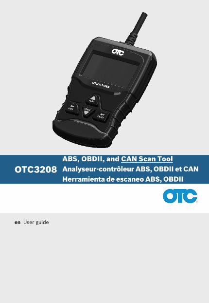
OTC3208
en User guide
ABS, OBDII, and CAN Scan Tool Analyseur-contrôleur ABS, OBDII et CAN Herramienta de escaneo ABS, OBDII
| OTC3208 | Operating instructions | en
575512 REV A | 05.2015Bosch Automotive Service Solutions Inc.
Safety PrecautionsThis user guide describes the features of the tool and provides step-by-step instructions for operating the tool . Always refer to and follow safety messages and test procedures provided by the manufacturer of the vehicle and the tool .
Read and understand the user guide before operating the tool .
An undetected or uncorrected vehicle malfunction could cause a serious, even fatal, accident . Important safety information in this user guide is intended to protect the user, bystanders, and the vehicle .
Signal Words and Symbols
WARNING!Indicates a possible hazardous situation that, if not avoided, could result in death or serious injury to op-erator or bystanders .
NOTICEIndicates a condition that may result in lost information .
B Indicates a single-step procedure .
Important Safety Messages
WARNING!This tool may not detect every malfunc-tion . Do not take chances with brakes, steering, or other vital functions of the vehi-cle . A serious accident could result .
Always wear ANSI-approved goggles for eye protection .
• Before testing a vehicle, make sure the transmission is in PARK (automatic transmis-sion) or NEUTRAL (manual transmission) and the parking brake is set .
• Never lay tools on the vehi-cle battery .
• Battery acid can burn . If contacted, rinse with water or neutralize with a mild base such as baking soda . If yousplashyoureyes,flushwith water and call a physi-cian immediately .
• Never smoke or have open flamesnearvehicle.Vaporsfrom gasoline and battery are explosive .
| Operating instructions | OTC3208 | en
575512 REV A | 05.2015 Bosch Automotive Service Solutions Inc.
• Do not use the tool if internal circuitry has been exposed to moisture . Internal shorts couldcauseafireanddam-age the vehicle or tool .
• Always turn the ignition key OFF when connecting or disconnecting electrical components unless other-wise instructed .
• Most vehicles are equipped with airbags . Follow vehicle service manual precautions . Serious injury or death could result from an unin-tended deployment .
WARNING!A vehicle airbag can open for several min-utes after the ignition has been turned off .
• Always follow vehicle manu-facturer’s warnings, cautions, and service procedures .
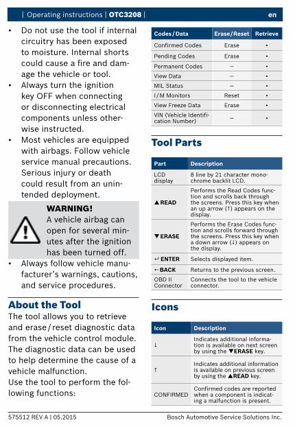
About the ToolThe tool allows you to retrieve and erase / reset diagnostic data from the vehicle control module . The diagnostic data can be used to help determine the cause of a vehicle malfunction .Use the tool to perform the fol-lowing functions:
Codes / Data Erase / Reset Retrieve
Confirmed Codes Erase •
Pending Codes Erase •
Permanent Codes — •
ViewData — •
MIL Status — •
I / M Monitors Reset •
ViewFreezeData Erase •
VIN(VehicleIdentifi-cation Number) — •
Tool Parts
Part Description
LCD display
8 line by 21 character mono-chrome backlit LCD .
READ
Performs the Read Codes func-tion and scrolls back through the screens . Press this key when an up arrow (#) appears on the display .
ERASE
Performs the Erase Codes func-tion and scrolls forward through the screens . Press this key when a down arrow ($) appears on the display .
ENTER Selects displayed item .
BACK Returns to the previous screen .
OBD II Connector
Connects the tool to the vehicle connector .
Icons
Icon Description
$Indicates additional informa-tion is available on next screen by using the ERASE key .
#Indicates additional information is available on previous screen by using the READ key .
CONFIRMEDConfirmed codes are reported when a component is indicat-ing a malfunction is present .
| OTC3208 | Operating instructions | en
575512 REV A | 05.2015Bosch Automotive Service Solutions Inc.
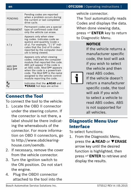
PENDING
Pending codes are reported when a problem occurs during the current or last completed drive cycle .
PERMANENTPermanent codes are a special type of confirmed code that only the vehicle can erase .
x / y
Appears only when view-ing codes . Indicates code se-quence and quantity (code x of y) . For example, “2 / 9” indi-cates that the 2nd of 9 codes reported by the computer mod-ule is being viewed .
ABS $##Mod $##
Appears only when viewing codes . Indicates the computer module that reported the code .ABS will appear if the code is an ABS code . Mod $## appears when the code is a powertrain code . The Mod $## is the name assigned to the vehicle control module reporting the code .
Indicates that the READ and ERASE hot keys are active
Connect the ToolTo connect the tool to the vehicle:1 . Locate the OBD II connector
under the steering column . If the connector is not there, a label should be there indicat-ing the whereabouts of the connector . For more informa-tion on OBD II connectors, go to http://www .obdclearing-house .com/oemdb .
2 . If necessary, remove the cover from the vehicle connector .
3 . Turn the ignition switch to the ON position . Do not start the engine .
4 . Plug the OBDII connector attached to the tool into the
vehicle connector . The Tool automatically reads Codes and displays the data . When done viewing data, press ENTER key to return to Diagnostic Menu .
NOTICEIf the vehicle returns a manufacturerspecificcode, the tool will ask if you wish to select the vehicle and then read ABS codes .If the vehicle doesn’t return a manufacturer specificcode,thetoolwill ask if you wish to select a vehicle to read ABS codes . ABS is not supported for all vehicles .
Diagnostic Menu User InterfaceTo select functions:1 . From the Diagnostic Menu,
press the READ or ERASE arrow key until the desired function is highlighted, then press ENTER to retrieve and display the results .
| Operating instructions | OTC3208 | en
575512 REV A | 05.2015 Bosch Automotive Service Solutions Inc.
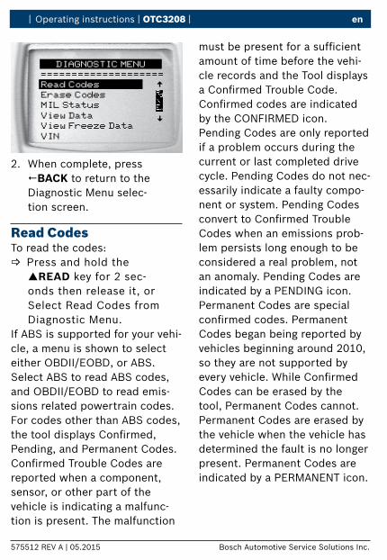
DIAGNOSTIC MENU
====================
Read Codes
Erase Codes
MIL Status
View Data
View Freeze Data
^^
VIN
2 . When complete, press BACK to return to the Diagnostic Menu selec-tion screen .
Read CodesTo read the codes:
B Press and hold the READ key for 2 sec-onds then release it, or Select Read Codes from Diagnostic Menu .
If ABS is supported for your vehi-cle, a menu is shown to select either OBDII/EOBD, or ABS . Select ABS to read ABS codes, and OBDII/EOBD to read emis-sions related powertrain codes .For codes other than ABS codes, thetooldisplaysConfirmed,Pending, and Permanent Codes . ConfirmedTroubleCodesarereported when a component, sensor, or other part of the vehicle is indicating a malfunc-tion is present . The malfunction
mustbepresentforasufficientamount of time before the vehi-cle records and the Tool displays aConfirmedTroubleCode.Confirmedcodesareindicatedby the CONFIRMED icon .Pending Codes are only reported if a problem occurs during the current or last completed drive cycle . Pending Codes do not nec-essarily indicate a faulty compo-nent or system . Pending Codes converttoConfirmedTroubleCodes when an emissions prob-lem persists long enough to be considered a real problem, not an anomaly . Pending Codes are indicated by a PENDING icon .Permanent Codes are special confirmedcodes.PermanentCodes began being reported by vehicles beginning around 2010, so they are not supported by everyvehicle.WhileConfirmedCodes can be erased by the tool, Permanent Codes cannot . Permanent Codes are erased by the vehicle when the vehicle has determined the fault is no longer present . Permanent Codes are indicated by a PERMANENT icon .
| OTC3208 | Operating instructions | en
575512 REV A | 05.2015Bosch Automotive Service Solutions Inc.
Vehicle SelectionVehicleSelectionwillbedis-played for Read Codes when a manufacturerspecificDTCisretrieved from the vehicle .
Erase CodesThe Erase function performs the following:
9 Erases codes (both ConfirmedandPendingDTCs) when erasing OBDII/EOBD codes . Permanent codes can only be erased by the vehicle .
9 May erase Freeze Data results depending on the vehcle .
9 Sets I / M Monitors to not ready .
NOTICEPerform Erase Codes function only after systems have been checked completely and DTCs have been written down .
To erase codes from the vehi-cle computer:1 . Set the ignition to Key On
Engine Off . Do NOT start the vehicle . The engine should not be running .
2 . Press and hold the ERASE key for 3 seconds then
release, or select Erase Codes from Diagnostic Menu; press ENTER .
3 . Whentheconfirmationmes-sage appears on the display, choose one of the follow-ing options .• To proceed with the opera-
tion: Press ENTER for YES .• To cancel the operation and
return to the Diagnostic Menu: Press BACK for NO .
4 . If ABS is supported for your vehicle, a menu is shown to select either OBDII/EOBD, or ABS . Select ABS to erase ABS codes, and OBDII/EOBD to erase emissions related powertrain codes .
The Tool will automatically per-form the Read Codes function after erasing codes . The Tool will then indicate the number of codes remaining .
NOTICEIf after erasing codes a DTC returns, the problem has not been fixedorotherfaultsare present .
MIL StatusMIL (Malfunction Indicator Lamp) status indicates if the
| Operating instructions | OTC3208 | en
575512 REV A | 05.2015 Bosch Automotive Service Solutions Inc.
vehicle computer is telling the MIL to illuminate when the engine is running .• MIL ON indicates that the
Malfunction Indicator Lamp should be ON .
• MIL OFF indicates that the Malfunction Indicator Lamp should be OFF .
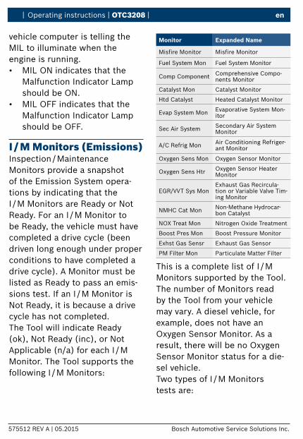
I / M Monitors (Emissions)Inspection / Maintenance Monitors provide a snapshot of the Emission System opera-tions by indicating that the I / M Monitors are Ready or Not Ready . For an I / M Monitor to be Ready, the vehicle must have completed a drive cycle (been driven long enough under proper conditions to have completed a drive cycle) . A Monitor must be listed as Ready to pass an emis-sions test . If an I / M Monitor is Not Ready, it is because a drive cycle has not completed .The Tool will indicate Ready (ok), Not Ready (inc), or Not Applicable (n/a) for each I / M Monitor . The Tool supports the following I / M Monitors:
Monitor Expanded Name
Misfire Monitor Misfire Monitor
Fuel System Mon Fuel System Monitor
Comp Component Comprehensive Compo-nents Monitor
Catalyst Mon Catalyst Monitor
Htd Catalyst Heated Catalyst Monitor
Evap System Mon Evaporative System Mon-itor
Sec Air System Secondary Air System Monitor
A/C Refrig Mon Air Conditioning Refriger-ant Monitor
Oxygen Sens Mon Oxygen Sensor Monitor
Oxygen Sens Htr Oxygen Sensor Heater Monitor
EGR/VVTSysMonExhaust Gas Recircula-tionorVariableValveTim-ing Monitor
NMHC Cat Mon Non-Methane Hydrocar-bon Catalyst
NOX Treat Mon Nitrogen Oxide Treatment
Boost Pres Mon Boost Pressure Monitor
Exhst Gas Sensr Exhaust Gas Sensor
PM Filter Mon Particulate Matter Filter
This is a complete list of I / M Monitors supported by the Tool . The number of Monitors read by the Tool from your vehicle may vary . A diesel vehicle, for example, does not have an Oxygen Sensor Monitor . As a result, there will be no Oxygen Sensor Monitor status for a die-sel vehicle .Two types of I / M Monitors tests are:
| OTC3208 | Operating instructions | en
575512 REV A | 05.2015Bosch Automotive Service Solutions Inc.
� Since DTCs Cleared - shows status of the monitors since the DTCs were last erased .
� This Drive Cycle - shows status of monitors since the start of the current drive cycle . Refer to the vehicle service manual for more detailed information on emission-related monitors and their status .
9 Some vehicles do not sup-port This Drive Cycle . If vehicle supports both types of monitors the I / M Monitors Menu displays .
View Freeze DataDisplays a snapshot of operat-ing conditions at the time the Diagnostic Trouble Code was created.SeePIDDefinitionsformore information .
VINTheVINfunctionallowsthetool to request the vehicle’s VINnumber.TheVINfunctionappliestomodel year 2000 and newer OBD II compliant vehicles .
System SetupSystem Setup allows:
• Display contrast to be changed
• Tool information to be viewed• Display to be checked• Operation of the keypad to
be checked• Memory of the Tool to
be checked• Units of measure to
be changed
View DataTheViewDatafunctionallowsreal time viewing of the vehicle’s computer module’s PID data . As the computer monitors the vehicle, information is simultane-ously transmitted to the Tool .ViewDataallowsthefollowingitems to be viewed on the Tool:
� Sensor data � Operation of switches � Operation of solenoids � Operation of relays
Multiple PIDs may be sent if vehi-cle is equipped with more than one computer module (for exam-ple a powertrain control mod-ule [PCM] and a transmission control module [TCM] .
| Operating instructions | OTC3208 | en
575512 REV A | 05.2015 Bosch Automotive Service Solutions Inc.
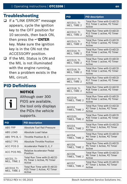
Troubleshooting � If a “LINK ERROR” message
appears, cycle the ignition key to the OFF position for 10 seconds, then back ON, then press the ENTER key . Make sure the ignition key is in the ON not the ACCESSORY position .
� If the MIL Status is ON and the MIL is not illuminated with the engine running, then a problem exists in the MIL circuit .
PID DefinitionsNOTICEAlthough over 300 PIDS are available, the tool only displays the PIDs the vehicle supports .
PID PID description
ABS FRP Absolute Fuel Rail Pressure
ABS LOAD AbsoluteLoadValue
ABS TPS B, C Throttle Position B, C
ABSLT TPS Absolute Throttle Position
ACC POS D Accelerator Pedal D, E, F
ACC POS REL Relative Accelerator Pedal Position
AECD1_TI-ME1, TIME 2
Total Run Time with EI-AECD #1 Timer 1 Active, #2 Timer Active
AECD10_TI-ME1, TIME 2
Total Run Time with EI-AECD #10 Timer 1 Active, #2 Timer Active
PID PID description
AECD11_TI-ME1, TIME 2
Total Run Time with EI-AECD #11 Timer 1 active, #2 Timer Active
AECD12_TI-ME1, TIME 2
Total Run Time with EI-AECD #12 Timer 1 active, #2 Timer Active
AECD13_TI-ME1, TIME 2
Total Run Time with EI-AECD #13 Timer 1 active, #2 Timer Active
AECD14_TI-ME1, TIME 2
Total Run Time with EI-AECD #14 Timer 1 active, #2 Timer Active
AECD15_TI-ME1, TIME 2
Total Run Time with EI-AECD #15 Timer 1 active, #2 Timer Active
AECD16_TI-ME1, TIME 2
Total Run Time with EI-AECD #16 Timer 1 active, #2 Timer Active
AECD17_TI-ME1, TIME 2
Total Run Time with EI-AECD #17 Timer 1 active, #2 Timer Active
AECD18_TI-ME1, TIME 2
Total Run Time with EI-AECD #18 Timer 1 active, #2 Timer Active
AECD19_TIME1, TIME 2
Total Run Time with EI-AECD #19 Timer 1 active, #2 Timer Active
AECD2_TIME1, TIME 2
Total Run Time with EI-AECD #2 Timer 1 Active, #2 Timer Active
AECD20_TIME1, TIME 2
Total Run Time with EI-AECD #20 Timer 1 active, #2 Timer Active
AECD3_TIME1, TIME 2
Total Run Time with EI-AECD #3 Timer 1 Active, #2 Timer Active
AECD4_TIME1, TIME 2
Total Run Time with EI-AECD #4 Timer 1 Active, #2 Timer Active
AECD5_TIME1, TIME 2
Total Run Time with EI-AECD #5 Timer 1 Active, #2 Timer Active
AECD6_TIME1, TIME 2
Total Run Time with EI-AECD #6 Timer 1 Active, #2 Timer Active
AECD7_TIME1, TIME 2
Total Run Time with EI-AECD #7 Timer 1 Active, #2 Timer Active
| OTC3208 | Operating instructions | en
575512 REV A | 05.2015Bosch Automotive Service Solutions Inc.
PID PID description
AECD8_TIME1, TIME 2
Total Run Time with EI-AECD #8 Timer 1 Active, #2 Timer Active
AECD9_TIME1, TIME 2
Total Run Time with EI-AECD #9 Timer 1 Active, #2 Timer Active
ALCOHOL Alcohol Fuel Percent
BARO PRS Barometric Pressure
BAT_PWR Hybrid Battery Pack Remain-ing Life
BP_A_ACT, B_ACT
Boost Pressure Sensor A, Sen-sor B
BP_A_CMD, B_CMD
Commanded Boost Pressure A, Pressure B
BP_A_STAT, B_STAT
Boost Pressure A Control Sta-tus, B Control Status
CACT 11, 12Charge Air Cooler Temper-ature Bank 1 Sensor 1 sup-ported, Sensor 2 supported
CACT 21,22Charge Air Cooler Temper-ature Bank 2 Sensor 1 sup-ported, Sensor 2 supported
CALC LOAD Calculated Engine Load
CAT TEMP11, TEMP12
Cataltic Converter Temp Bank1, Temp Bank 3
CAT TEMP21, TEMP22
Cataltic Converter Temp Bank2, Temp Bank 4
CLR DIST Distance since erase
CLR TIME Minutes Run since Erase
CLR TRPS Warmups Since Erase
CMD EQ RAT Commanded Equivalence Ratio
COOLANT Engine Coolant Temp
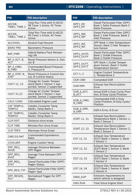
DPF_REG_AVGD
Average Distance Between DPF Regen
DPF_REG_AVGT
Average Time Between DPF Regen
DPF_REG_STAT
Diesel Particulate Filter (DPF) Regen Status
DPF_REG_TYP Diesel Particulate Filter (DPF) Regen Type
DPF_REGEN_PCT
Normalized Trigger for DPF Regen
PID PID description
DPF1_DP, DPF2_DP
Diesel Particulate Filter (DPF) Bank 1 Delta Pressure Bank 2 Delta Pressure
DPF1_INP, DPF2_INP
Diesel Particulate Filter (DPF) Bank 1 Inlet Pressure, Bank 2 Inlet Pressure
DPF1_INT, DPF2_INT
DPF Bank 1 Inlet Temperature Sensor, Bank 2 Inlet Tempera-ture Sensor
DPF1_OUTP, DPF2_OUTP
Diesel Particulate Filter (DPF) Bank 1 Outlet Pressure, Bank 2 Outlet Pressure
DPF1_OUTT, DPF2_OUTT
DPF Bank 1 Outlet Temper-ature Sensor, Bank 2 Outlet Temperature Sensor
ECT 1, 2 Engine Coolant Temperature 1, Temperature 2
EGR CMD Comanded EGR
EGR ERR Exhaust Gas Recirculation Error
EGR_A_ACT, B_ACT
Actual EGR A Duty Cycle / Posi-tion, B Duty Cycle / Position
EGR_A_CMD, B_CMD
Commanded EGR A Duty Cycle / Position, B Duty Cycle / Position
EGR_A_ERR, B_ERR EGR A Error, B Error
EGRT 11, 21Exhaust Gas Recirculation Temperature Bank 1 Sensor 1, Bank 2 Sensor 1
EGRT 12, 22Exhaust Gas Recirculation Temperature Bank 1 Sensor 2, Bank 2 Sensor 2
EGT 11, 21Exhaust Gas Temperature (EGT) Bank 1 Sensor 1, Bank 2 Sensor 1
EGT 12, 22Exhaust Gas Temperature (EGT) Bank 1 Sensor 2, Bank 2 Sensor 2
EGT 13, 23Exhaust Gas Temperature (EGT) Bank 1 Sensor 3, Bank 2 Sensor 3
EGT 14, 24Exhaust Gas Temperature (EGT) Bank 1 Sensor 4, Bank 2 Sensor 4
EMIS_SUP Emission requirements to which vehicle is designed
ENG RUN Time Since Engine Start
| Operating instructions | OTC3208 | en
575512 REV A | 05.2015 Bosch Automotive Service Solutions Inc.
PID PID description
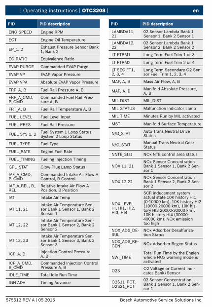
ENG SPEED Engine RPM
EOT Engine Oil Temperature
EP_1, 2 Exhaust Pressure Sensor Bank 1, Bank 2
EQ RATIO Equivalence Ratio
EVAPPURGE CommandedEVAPPurge
EVAPVP EVAPVaporPressure
EVAPVPA AbsoluteEVAPVaporPressure
FRP_A, B Fuel Rail Pressure A, B
FRP_A_CMD, B_CMD
Commanded Fuel Rail Pres-sure A, B
FRT_A, B Fuel Rail Temperature A, B
FUELLEVEL Fuel Level Input
FUEL PRES Fuel Rail Pressure
FUEL SYS 1, 2 Fuel System 1 Loop Status, System 2 Loop Status
FUEL TYPE Fuel Type
FUEL_RATE Engine Fuel Rate
FUEL_TIMING Fueling Injection Timing
GPL_STAT Glow Plug Lamp Status
IAF_A_CMD, B_CMD
Commanded Intake Air Flow A Control, B Control
IAF_A_REL, B_REL
Relative Intake Air Flow A Position, B Position
IAT Intake Air Temp
IAT 11, 21Intake Air Temperature Sen-sor Bank 1 Sensor 1, Bank 2 Sensor 1
IAT 12, 22Intake Air Temperature Sen-sor Bank 1 Sensor 2, Bank 2 Sensor 2
IAT 13, 23Intake Air Temperature Sen-sor Bank 1 Sensor 3, Bank 2 Sensor 3
ICP_A, B Injection Control Pressure A, B
ICP_A_CMD, B_CMD
Commanded Injection Control Pressure A, B
IDLE_TIME Total Idle Run Time
IGNADV Timing Advance
PID PID description
LAMBDA11, 21
02 Sensor Lambda Bank 1 Sensor 1, Bank 2 Sensor 1
LAMBDA12, 22
02 Sensor Lambda Bank 1 Sensor 2, Bank 2 Sensor 2
LT FTRM1 Long Term Fuel Trim 1 or 3
LT FTRM2 Long Term Fuel Trim 2 or 4
LT SEC FT1, 2, 3, 4
Long Term Secondary O2 Sen-sor Fuel Trim 1, 2, 3, 4
MAF, A, B Mass Air Flow, A, B
MAP, A, B Manifold Absolute Pressure, A, B
MIL DIST MIL_DIST
MIL STATUS Malfunction Indicator Lamp
MIL TIME Minutes Run by MIL activated
MST Manifold Surface Temperature
N/D_STAT Auto Trans Neutral Drive Status
N/G_STAT Manual Trans Neutral Gear Status
NNTE_Stat NOx NTE control area status
NOX 11, 21NOx Sensor Concentration Bank 1 Sensor 1, Bank 2 Sen-sor 1
NOX 12,22NOx Sensor Concentration Bank 1 Sensor 2, Bank 2 Sen-sor 2
NOXLEVELHI, HI1, HI2, HI3, HI4
SCR inducement system actual state 10K history HI1 (0-10000 km), 10K history HI2 (10000-20000 km), 10K his-tory HI3 20000-30000 km), 10K history HI4 (30000-40000 km): NOx emission too high
NOX_ADS_DE-SUL
NOx Adsorber Desulfuriza-tion Status
NOX_ADS_RE-GEN NOx Adsorber Regen Status
NWI_TIMETotal Run Time by the Engien whicle NOx warning mode is activated
O2S O2VoltageorCurrentindi-cates Bank / Sensor
O2S11_PCT, O2S21_PCT
02 Sensor Concentration Bank 1 Sensor 1, Bank 2 Sen-sor 1
| OTC3208 | Operating instructions | en
575512 REV A | 05.2015Bosch Automotive Service Solutions Inc.
PID PID description
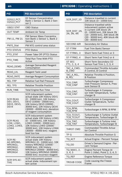
O2S12_PCT, O2S22_PCT
02 Sensor Concentration Bank 1 Sensor 2, Bank 2 Sen-sor 2
OBD2 STAT OBD Status
OUT TEMP Ambient Air Temp
PM 11, PM 21PM Sensor Mass Concentra-tion Bank 1 Sensor 1, Bank 2 Sensor 1
PNTE_Stat PM NTE control area status
PTO STATUS PTO Status
PTO_STAT Power Take Off (PTO) Status
PTO_TIME Total Run Time With PTO Active
REAG_DEMD Average Demanded Reagent Consumption
REAG_LVL Reagent Tank Level
REAG_RATE Average Reagent Consumption
REL FRP Relative Fuel Rail Pressure
REL TPS Relative Throttle Position
RUN_TIME Total Engine Run Time
SCR REAG DEV,DEV1,DEV2,DEV3,DEV4
SCR inducement system actualstate10KhistoryDEV1(0 - 10000 km), 10K history DEV2(10000-20000km),10KhistoryDEV3(20000-30000km),10KhistoryDEV4(30000 - 40000 km): deviation of reagent consumption
SCR REAG LOW, LOW1, LOW2, LOW3, LOW4
SCR inducement system actual state 10K history LOW1 (0 - 10000 km), 10K history LOW2 (10000 - 20000 km), 10K history LOW3 (20000 - 30000 km), 10K history LOW4 (30000 - 40000 km): reagent level too low
SCR RE-AG WRONG, WRONG1, WRONG2, WRONG3, WRONG4
SCR inducement system actual state 10K history WRONG1 (0 - 10000 km), 10K history WRONG2 (10000 - 20000 km), 10K history WRONG3 (20000 - 30000 km), 10K history WRONG4 (30000 - 40000 km): incorrect reagent
SCR SYS AC-TIVE
SCR inducement system actual state: inducement sys-tem active
PID PID description
SCR_DIST_1D Distance travelled in current 10K block (0 - 10000 km)
SCR_DIST_1N, 2N, 3N, 4N
Distance travelled while inducement system active in current 10K block 1N (0 - 10000 km), 20K block 2N (10 - 20000 km), 30K block 3N (20 - 30000 km), 40K block 4N (30 - 40000 km)
SECOND AIR Secondary Air Status
ST FTRM Fuel Trim Bank / Sensor
ST FTRM1, 3 Short Term Fuel Trim1 or 3
ST FTRM2, 4 Short Term Fuel Trim2 or 4
ST SEC FT1, 2, 3, 4
Short Term Secondary O2 Sensor Fuel Trim 1, 2, 3, 4
TAC_A_CMD, B_CMD
Commanded Throttle Actuator A Control, B Control
TAC_A_REL, B_REL
Relative Throttle A Position, B Position
TCA_CINP, TCB_CINP
Turbocharger Compressor Inlet Pressure Sensor A, Pres-sure Sensor B
TCA_CINT, TCB_CINT
Turbocharger A Compres-sor Inlet Temperature, Turbo-charger B
TCA_COUT, TCB_COUT
Turbocharger A Compressor Outlet Temperature, Turbo-charger B
TCA_RPM, TCB_RPM Turbocharger A RPM, B RPM
TCA_TCOUT, TCB_TCOUT
Turbocharger A Turbine Outlet Temperature, Turbocharger B
TCA_TINT, TCB_TINT
Turbocharger A Turbine Inlet Temperature, Turbocharger B
THROT CMD Commanded Throttle Actua-tor Control
TP G Absolute Throttle Position G
TQ_ACT Actual Engine - Percent Torque
TQ_DD Driver's Demand Engine - Per-cent Torque
TQ_MAX1, 2, 3, 4, 5
Engine Percent Torque At Point 1 (Idle), Point 2, 3, 4, 5
TQ_REF Engine Reference Torque
TROUB CODE Code causing the Freeze Frame
| Operating instructions | OTC3208 | en
PID PID description
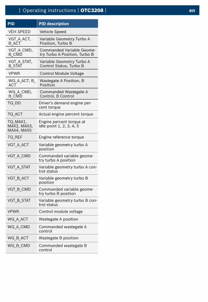
VEHSPEED VehicleSpeed
VGT_A_ACT,B_ACT
VariableGeometryTurboAPosition, Turbo B
VGT_A_CMD,B_CMD
CommandedVariableGeome-try Turbo A Position, Turbo B
VGT_A_STAT,B_STAT
VariableGeometryTurboAControl Status, Turbo B
VPWR ControlModuleVoltage
WG_A_ACT, B_ACT
Wastegate A Position, B Position
WG_A_CMD, B_CMD
Commanded Wastegate A Control, B Control
TQ_DD Driver's demand engine per-cent torque
TQ_ACT Actual engine percent torque
TQ_MAX1, MAX2, MAX3, MAX4, MAX5
Engine percent torque at idle point 1, 2, 3, 4, 5
TQ_REF Engine reference torque
VGT_A_ACT VariablegeometryturboAposition
VGT_A_CMD Commanded variable geome-try turbo A position
VGT_A_STAT VariablegeometryturboAcon-trol status
VGT_B_ACT VariablegeometryturboBposition
VGT_B_CMD Commanded variable geome-try turbo B position
VGT_B_STAT VariablegeometryturboBcon-trol status
VPWR Control module voltage
WG_A_ACT Wastegate A position
WG_A_CMD Commanded wastegate A control
WG_B_ACT Wastegate B position
WG_B_CMD Commanded wastegate B control