absolute calibration of radio telescopes with a periscopic reflector
TRANSCRIPT
ABSOLUTE CALIBRATION OF RADIO TELESCOPES
WITH A PERISCOPIC REFLECTOR
S. A. Pelyushenko and V. I. Chernyshev UDC 621.396.677.861.4
A method for the absolute calibration of a radio telescope with a periscopic reflector using the radio emission of blackbodies at various temperatures is proposed and tested on the basis of the autocollimation principle of measurements of antenna parameters. Measurements are made of the effective area of the RT-25 • 2 radio
telescope: Aeff = 28.8 __+ I m 2 at X = 8.6 mm and Aef f =28 .2 + 1.2 m 2 at ~ = 6.1 ram. The brightness
temperature of Jupiter, Tbr = 158 + 20~ is measured on the basis of the absolute calibration of a radio
telescope which is performed.
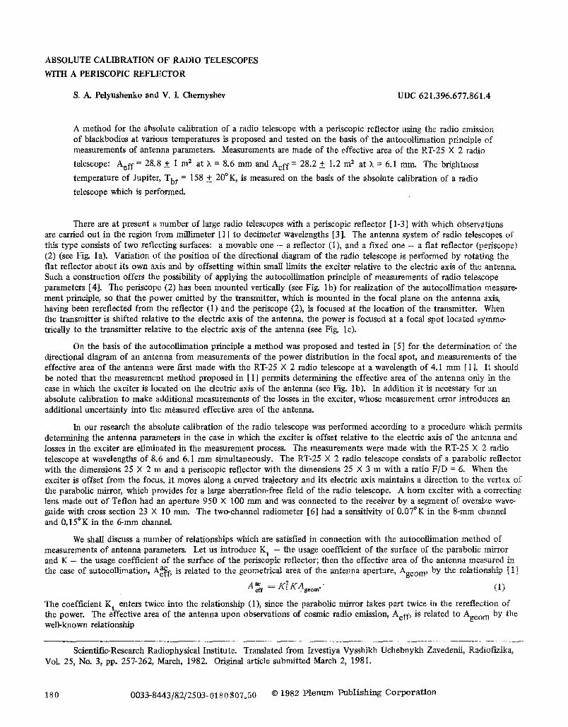
There are at present a number of large radio telescopes with a periscopic reflector [1-3] with which observations are carried out in the region from millimeter [ 1] to decimeter wavelengths [3]. The antenna system of radio telescopes of this type consists of two reflecting surfaces: a movable one - a reflector (1), and a fixed one - a flat reflector (periscope) (2) (see Fig. la). Variation o f the position of the directional diagram of tile radio telescope is performed by rotating the flat reflector about its own axis and by offsetting within small limits the exciter relative to the electric axis of the antenna. Such a construction offers the possibility of applying the autocollimation principle of measurements of radio telescope parameters [4]. The periscope (2) has been mounted vertically (see Fig. lb) for realization of the autocollimation measure- ment principle, so that the power emitted by the transmitter, which is mounted in the focal plane on the antenna axis, having been rereflected from the reflector (1) and the periscope (2), is focused at the location of the transmitter. When the transmitter is shifted relative to the electric axis of the antenna, the power is focused at a focal spot located symme- tricaUy to the transmitter relative to the electric axis of the antenna (see Fig. 1 c).
On the basis of the autocollimation principle a method was proposed and tested in [5] for the determination of the directional diagram of an antenna from measurements of the power distribution in the focal spot, and measurements of the effective area of the antenna were first made with the RT-25 • 2 radio telescope at a wavelength of 4.1 ram [ 1 ]. It should be noted that the measurement method proposed in [ 1 ] permits determining the effective area of the antenna only in the case in which the exciter is located on the electric axis of the antenna (see Fig. lb). In addition it is necessary for an absolute calibration to make additional measurements of the losses in the exciter, whose measurement error introduces an additional uncertainty into the measured effective area of the antenna.
In our research the absolute calibration of the radio telescope was performed according to a procedure which permits determining the antenna parameters in the case in which the exciter is offset relative to the electric axis of the antenna and losses in the exciter are eliminated in the measurement process. The measurements were made with the RT-25 • 2 radio telescope at wavelengths of 8.6 and 6.1 mm simultaneously. The RT-25 • 2 radio telescope consists of a parabolic reflector with the dimensions 25 X 2 m and a periscopic reflector with the dimensions 25 • 3 m with a ratio F/D = 6. When the exciter is offset from the focus, it moves along a curved trajectory and its electric axis maintains a direction to the vertex of the parabolic mirror, which provides for a large aberration-free field of the radio telescope. A horn exciter with a correcting lens made out of Teflon had an aperture 950 X 100 mm and was connected to the receiver by a segment of oversize wave- guide with cross section 23 • 10 mm. The two-channel radiometer [6] had a sensitivity o f 0.07~ in the 8-mm channel and 0.15~ in the 6-mm channel.
We shall discuss a number of relationships which are satisfied in connection with the autocollimation method of measurements of antenna parameters. Let us introduce K 1 - the usage coefficient of the surface of the parabolic mirror and K - the usage coefficient of the surface of the periscopic reflector; then the effective area of the antenna measured in the case of autocollimation, Aa~f, is related to the geometrical area of the antenna aperture, Ageo m, by the relationship [ 1]
A~eff = K[KAgoom' (I)
The coefficient K t enters twice into the relationship (1), since the parabolic mirror takes part twice in the rereflection of the power. The effective area of the antenna upon observations of cosmic radio emission, Aef f, is related to Ageo m by the well-known relationship
Scientific-Research Radiophysical Institute. Translated from Izvestiya Vysshikh Uchebnykh Zavedenii, Radiofizika, Vol. 25, No. 3, pp. 257-262, March, 1982. Original article submitted March 2, 1981.
180 0033-8443/8,2/2503-0180507.50 �9 1982 P lenum Publ ish ing C o r p o r a t i o n
2 ~ 2
b e.
Fig. 1. A - A ) Focal plane of the antenna; the hatched region is the electric axis of the antenna; 1) parabolic mirror, 2) periscopic reflector, a n d 3) exciter of the transmitter (receiver).
A elf : Kt KAgeom" (2)
it is easy to see from (1) and (2) that �9 .AaC A~eotr)'.l~ A e f f = ( K , e l f �9 ( 3 )
ac Thus one can determine from measurements of Aeff the effective area of the antenna Aeff with an error of a factor of f'K.
Measurements of the effective area of the antenna were conducted using the radiation of reference blackbodies at various temperatures [7]: at temperature o f the surroundings T O and at the boiling temperature of liquid nitrogen Tnitr.
The periscopic reflector was mounted vertically, and the exciter was offset by a distance L relative to the electric axis of the antenna (see Fig. 1 b). A reference blackbody at temperature To, and then a blackbody at the temperature Tnitr, was
positioned symmetrically to the exciter at a distance - L . The increment to the antenna temperature is equal to
ATal = r = (Tbo r - T ~ ; ) Aeafcf (,f.f F(x. ! /)dxdy ) ~q/D', (4) T
where An 1 is the increment to the readings of the output device of the radiometer; o~, a proportionality coefficient; To br
and T br brightness temperatures of reference blackbodies at the temperatures T O and Tnitr, respectively; F(x. y), power nitr, distribution in the focal spot; ~ Fdxd b, , integrated within the limits of the linear dimensions of the reference black-
r bodies; x and y , coordinates in the focN plane with the origin of coordinates at the point F = Fmax; X, effective wave-
length; and r~, efficiency of the exciter.
Reference blackbodies of rectangular shape (100 X 15 cm) were made out of absorbing material with a power reflection coefficient R = 0.8 + 0.2% in the 6 -8 -mm region and were located in boxes made out of radio engineering foam plastic 25 mm thick. Expressions are obtained in [71 for the brightness temperature of standards of similar construction:
br r~,, = [r~,~ (t --R) + rb R(1--~)] (1 - ~ ) + T~ (5)
T~0r= [ T 0 ( 1 , R ) +To R(1--x)]( i - -*) + Tbr w 2
where T b is the background radiation incident on the standard; T br intrinsic radiation of the wall of the foam plastic w l , 2 ~
box flooded with nitrogen and at the temperature T o, respectively; and r, optical thickness of the foam plastic wall. Then
the difference in the brightness temperatures which enter into (4) is equal to
Tb, .vb, --_ ( r o - - r , ~ t ~ ) ( 1 - - R ) ( 1 - - ~ ) + ( T ~ ~w~). (6) 0 - - ~ n i t r
It is necessary in connection with measurements of the increment to tile antenna temperature (4) to take into account the losses in the signal on the path from the standards to the exciter. The overall path length of the signal for ~ e RT-25 X 2 radio telescope due to double reflection is equal to L = 600 m, and the signal decreases by a factor of
m_=e-~L where • is the absorption coefficient in oxygen and water vapor along a path L: • ----- •215 apo, anda ==- • �9
The absorption coefficients are equal to: xox = 0.033 dB/km and a = 0.0093 (dB/km)/(g/m) at a wavelength of 8.6 mm
mad • = 0.19 dB/km and a = 0.015 (dB/km)/(g/m) at a wavelength of 6.1 mm [8, 13]. The estimates made showed
that when the absolute humidity at the Earth's surface 0o changes from 0 to 20 g/m s m varies from 0.996 to 0.970 at a
wavelength o f 8.6 mm and from 0.975 to 0.940 at a wavelength of 6.1 ram. The measurements were made at P0 = 3.0
181
O g/m, T o = 9 C, and a pressure of 1004 mbar; the correction for absorption is m = 0.97 +_ 0.01 and m = 0.99 _+ 0.005 at wavelengths of 6.1 and 8.6 ram, respectively.
In order to take account of possible diffraction corrections to the brightness temperature of the standards [9], the measurements of the increment to the antenna temperature were made with standards of significantly different sizes: 100 X 15 cm and 27 • 10 cm. The standards overlapped the focal spot at the levels: 0.03, 0.15 and 0.25, 0.89 at a wavelength of 8.6 mm and 0.01, 0.1 and 0.1, 0.75 at a wavelength of 6.1 mm in the horizontal and vertical planes, respectively.
The thermal calibration of the antenna temperatures was performed using the radiation of standard blackbodies 100 X 15 cm in size at different temperatures T o and Tnitr which were placed in front of the exciter aperture. The
increment to the antenna temperature is equal to
br ATa2 - - ekn2 = (To ~ - Tniu) ~, (7)
where An 2 is the increment to the readings of the output device of the radiometer. Having taken the ratio of (7) to (4),
one can determine the effective area of the antenna:
=
We note that the difference in the brightness temperatures in (4) and (7) is determined by one and the same expression (6), since one and the same standards are used in connection with the measurements and the calibration. Thus the need for
br declines, since they are eliminated by virtue of accurate measurements of such parameters of the standards as R, r, and T w
the thermal calibration. In connection with the thermal calibration the standards are posit ioned close to the exciter; there- fore an effect on the measurement results from interference of the intrinsic noise of the receiver is possible upon its reflec- tion from the standards [ 121. Measurements of T b with the help of a metal foil covering the exciter aperture have shown
that the maximum correction due to interference can amount to +2.5~ and since the difference in the temperature of the standards enters into (7), one can neglect this correction with an error of 0.5%.
One can eliminate the uncertainty in Aef f due to the coefficient J 'K, as was shown in [ 1 ], by estimating its value on
the basis of the known parameters of the RT-25 • 2 radio telescope and assuming that the usage coefficient of the flat reflector is determined mainly by the losses due to inaccuracy in the fabrication of its surface, diffraction losses, and area losses by panel mismatch gaps~ The signal losses on the flat reflector due to error in the fabrication of its surface are eqt~al to [31
K2 = exp [ - - (4ZtZm.sq./~) 2]. (9)
For the RT-25 X 2Om.sq " 0.1 mm, K 2 = 0 . 9 8 + 0 . 0 1 a t X = 8 . 6 m m a n d K 2 8 0 . 9 6 + 0.01 at ), = 6 . 1 m m . The decrease
in signal due to diffraction losses [ 14] is no more than 3-4% (K 3 = 0.97-0.96), and 1% is lost by paael mismatch gaps (K 4 =
0.99). Thus, the quantity ~ = 1/K~ Ks K4 is equal to 0.96 + 0.02 at wavelengths of 8.6 and 6.1 ram, respectively.
Measurements made with standards of different sizes have shown that the diffraction correction to the brightness temperature o f the standards is less than 1-2%.
Thus the total error of the absolute measurements is equal to
n~ , (10) n
where o n are the errors of the independent parameters, viz.: a~ - due to instrumentation noise; ~ - due to uncertainty _ b r . of the absorption on the standard-exciter path; 0 3 - errors in the determination of (T br Tnitr), % - errors in calculating
S Fdxdg; c~s -- errors in estimating K; ~6 -- errors in estimating the diffraction corrections; and o~ - estimates in the r
interference correction. With all the errors taken into account
qs,s m m = 1/12+ 0-72 + 22 -]- 12 + 22 + 12 + 0.52 = 3,5% ( I D
o's.l m m ~ ~ /2 2 + 1-5 2 + 2 2 + 1-5 2 + 2 2 + lU + 0-5~ ~ - 4 . 4 % .
182
As a result of measurements by the described procedure the effective area of the RT-25 X 2 radio telescope was determined with the errors (11) taken into account: Aef f = 28.8 + 1.0 m 2 at X = 8.6 mm and Aeff = 28.4 + 1.(3 m 2 at
X = 8.6 mm with exciter offsets of 121X and 279X; Aef f = 28.2 + 1.2 m 2 at X = 6.1 ~~m and Aef f = 27.8 + 1.2 m 2
at X = 6.228 mm with exciter offsets of 168 and 385X, respectively. These measurements show that the high engineering parameters of the antenna system of the RT-25 X 2 radio telescope offer the possibility of making measurements o f cosmic radiation with an offset of the exciter relative to the electric axis of the antenna by ~400 X (with a signal loss no greater than 1.5%). The directional diagrmns were also measured by the autocollimation method using standard disks at various temperatures; the halfvddths of the directional diagrams are equal to 1' X 10' at X = 6.1 mm and 1'.5 • 15' at X = 8.6 mm.
All the measurements and calculations were made with the use of a measuring-calculating unit [1 I] which included a t5-VSM-5 computer. The measurement data were prodessed by the measuring-calculating unit in real time, and
An:. 2, SJ Fdxdy and Aef f were determined (the directional diagram of the antenna F was approximated by a Gaussian r
function using the method of least squares). The measurement results were output to an I~UM-23 printer.
The effective area o f the antenna was measured also in connection with observations of Jupiter at a wavelength of 8.6 ram. If one takes the brightness temperature of Jupiter to be equal to Tbr = 155 +__25~ [101, then one can determine the effective area of the antenna from the formula
A~ff = (AT~ ~,2/Tb, ~ Fdfg) e~, (12) ~m
where AT a is the increment to the antenna temperature upon passage of the source through the directional diagram of the
antenna; y, absorption in the atmosphere at the culmination altitude of the source; X, wavelength; and ~2 m, angular dimensions of Jupiter during the time of the measurements.
The measurement of the increment to the antenna temperature from the source was made with the measuring- calculating u_nit by convolution o f the directional diagram of the antenna with the response to the passage of the source through the directional diagram using the method of least squares [ 15]; the halfwidth of the response, the increment to the antenna temperature, and the instant of passage of the source through the center of tile diagram were determined. The measurements showed that Aeff = 28 + 4.5 m 2 ; the error is produced mainly by the uncertainty in Tbr. . Using the
value of Aeff obtained by us from the absolute calibration, one can determine the brightness temperature of Jupiter. The
error in the measurements is determined by the indeterminacy oAef f = +3.5%, the error in measurement of the absorption
at the culmination altitude of the source +6%, and the receiver noise o n = +10%. The brightness temperature of Jupiter
is equal to Tbr = 158 + 20~
It should be noted that the usage coefficient of the antenna surface obtained from our measurements at wavelengths o f 8.6 and 6.1 mm (efficiency = 0.57) is less than at X = 4.1 mm [1 ] . This is evidently related to the fact that the focal box of the RT-25 • 2 radio telescope, where the exciters and the receiver are located, was calculated for operation at wavelengths shorter than 4 mm; therefore the maximum possible size of the exciter aperture in the vertical direction (with- out vignetting of the exciter aperture by structural elements of the focal box) does not exceed 100 cm. Due to this the dimensions of the exciter (95 • 10 cm) were smaller than are required from the conditions of optimal irradiation of the parabolic mirror in the 6~8 mm range.
The results of our research show that the method of absolute calibration using blackbodies at various temperatures broadens the possibilities of the autocollimation principle of measurements of antenna parameters and permits performing a passive calibration of the gain of radio telescopes with an error no worse than +4-5%.
The authors are grateful to A. G. Kistyakov mad N. M. Tseittin for their attention to the research and for a useful discussion.
LITERATURE CITED
1. A .G . Kdslyakov, V. I. Chernyshev, A. A. Nosov, and Yu. P. Shandra, Izv. Vyssh. Uchebn. Zaved., Radiofiz., 16, No. 9, 1409 (1973).
2. No A. Esepkina, Do V. Korol'kov, and Yu. N. Pariiskii, Radiometers and Radio Telescopes [in Russian], Nauka, Moscow (1973).
3. D.D. Kraus, Radio Astronomy [Russian translation], Soy. Radio, Moscow (1973). 4o A~ D. Maksutov, The Investigation and Fabrication of Astronomical Optics [in Russian], Gostekhizdat, Moscow (1948). 5. V. Yu. Petrun'kin and N. Ao Esepkina, Radiotekh. Elektron., 10, No. 12, 2236 (1965). 6. So A. Pelyushenko, Izv. Vyssh. Uchebn. Zaved., Radiofiz., 1__9, No. 11, 1750 (1976). 7. K.S. Stankevich, Radiotekh. Elektron., 14, No. 3, 528 (1969).
183
8. S.A. Zhevakin and A. P. Naumov, Izv. Vyssh. Uchebn. Zaved., Radiofiz., 9, No. 3, 433 (1966). 9. N.M. Tseitlin, Antenna Engineering and Radio Astronomy [in Russian], Soy. Radio, Moscow (1976). 10. B.L. Ulrich, J. R. Cogdell, and J. H. Davis, Icarus, 1_?, No. 1, 59 (1973). 11. D.A. Dmitrenko, L. V. Dmitrenko, V. A. Kolotilkin, V. S. Beagon, V. I. Turchin, and S. A. Pelyushenko,
Proceedings of Eleventh All-Union Radio Astronomical Conference [in Russian], Aka& Nauk Arm. SSR, Erevan (1978).
12. K.S. Stankevich and V. P. Ivanov, Izv. Vyssh. Uchebn. Zaved., Radiofiz., 14, No. 12, 1787 (1971). 13. S.A. Zhevakin and A. P. Naumov, Radiotekh. Elektron., 1_0, No. 6, 987 (1965). 14. G.Z. Alzenberg, V. G. Yampol'skii, and O. N. Tereshin, Antennas of Ultrashort Waves [in Russian], Svyaz', Moscow
(1977). 15. M.M. Davis, Bull. Astron. Inst. Netherlands, 1_99, No. 4, 201 (1967).
ELECTROSTATIC ION-CYCLOTRON WAVES NEAR THE
PLASMAPAUSE IN THE EARTH'S MAGNETOSPHERE
O. A. Molchanov and L E. Sharko UDC 533.9 + 550.388
We show that ion cyclotron instabilities with wavelengths on the order of 102-103 meters may develop over several hours near the plasmapause in the magnetosphere. These characteristic times fully agree with the usual ideas concerning the lifetimes of energetic particles near the plasmapause. We note that the presence of ion cyclotron waves with K "~ 10"2-10 "3 meters should lead to an effectively destructive interaction with atmos- pheric whistler waves that may lead to further growth of the ion cyclotron background.
The existence of ELF waves (1-300 Hz) in the earth's magnetosphere has been known for a long time [ t ]. In the majority of cases, the frequency of these waves satisfies the inequality c0 < 0~B~ (~0~i is the proton ion cyclotron frequency),
the waves are circularly polarized, and are identified on the earth as oscillations in the transmission coefficient. Observa- tions from orbiting satellites, however, have provided information on another class of ELF waves which, as a rule, have frequencies ~o > ~o Bi, are electrostatic or almost electrostatic, and propagate transverse to the external magnetic field
(~ "~ ~/2). Such oscillations were detected for the first time on the OGO-3 satellite [2], where it was shown that 2o~ < e~
< (0Bgm (t0Bgm " ~ (O)BiO3.Be)l/2), that the signal was received in a narrow region near the equatorial plane of the
magnetosphere (A~ '~ 2 ~ in the region of the plasmapause (L = 4-5), and that they propagated practically perpendicular to
the magnetic field (A~ = ~ - ~/2 << 1 ~ . A similar phenomenon was detected in the equatorial plane of the plasmasphere
(L = 2-5) by the IMP-6 and Hawkeye-1 satellites and was described in [3], where it was shown that the noise occupied a range of from several hertz to around 100-200 Hz, that it had a distinctly bandlimited structure with A~o from several hertz to tens of hertz, and that it was highiy localized near the magnetic equator. Similar results observed by Hawkeye-1 (L > 3) were reported in Ref. 4, where it was additionally shown that the signal was electrostatic and was observed, as a rule, near the plasmapause in the presence of strong plasma density gradients (a = [(l/n) (On/Ox)] -1 N 0.1R~ -~ 6 �9 i03 m).
Finally, analogous oscillations were observed by GEOS-1 in the range L = 5-7 where, in distinction to the preceding cases, a thorough spectral analysis was performed and it was shown that the signals Co > co Bi) were narrowband with frequencies
practically coinciding with the harmonics co Bi, the maximum amplitudes occurring at the 4th to 8th harmonics ~o Bi" Some-
times "satellites" appeared in the radiation shifted by "~+~ Bi/4 from the fundamental frequency [5].
The first attempt to explain such phenomena was presented in [6], where it was shown that an instability at frequencies o~ ~ o~p~ >> o ~ arises in the presence of a conical anisotropy of energetic protons (E '~ 50 keV). A distribution
function for hot ions was used that took into account the conical anisotropy, which, as shown in [7], adequately describes the actually recorded characteristics of energetic particles outside the plasmasphere.
An analysis of the measurements of energetic particles by the Explorer-45 satellite [8] led the authors [9] to the conclusion that this same distribution function, slightly modified, also is a good description of the actual data inside the
Institute of Terrestrial Magnetism, the Ionosphere, and the Propagation of Radiowaves (IZMIRAN). Translated from Izvestiya Vysshikh Uchebnykh Zavedenii, Radiofizika, Vol. 25, No. 3, pp. 263-268, March, 1982. Original article submitted May 18, 1981.
184 0033-8443[8212503-0184 $07.50 �9 1982 Plenum Publishing Corporat ion