absorption chillers - ppiway.com · electric power & primary interlock wiring factory -...
TRANSCRIPT

Absorption Chillers
TGG, TBG, TEG, TUG, 3.9 TBS, Gene-Link series
Stable Chilled Water Outlet TemperaturePID control is applied to maintain constant chilled water outlet temperature. When the cooling load changes, the chiller adjuststhe amount of heat used to regenerate the desiccant. Temperature control is +/- 1.0ᵒC.
Automatic De-crystallization SystemTo prevent crystallization, the concentration of the LiBr solution is controlled by adjusting the heat input. The chiller monitors the temperature of Chilled Water, Cooling Water,and Solution for this purpose.If the Cooling Water temperature decreases or the load decreases, the chiller will automatically decrease the heat input to prevent crystallization.
Easy Setting of Chilled Water Outlet TemperatureSetpoints can be changed from the HMI on the chiller or remotely through LonWorks communication.
High Airtight StructureThe body of the chiller is robotically welded and checked for leaks by filling with helium in a controlled space. No sight glasses and the minimum number of valves and screws havebeen used to achieve maximum airtightness. This prolongs the life of the chiller and decreases the maintenance.
Standard Features:Automatic restart in case of a power failure Maximum operating pressure of 784 kPa (114 psi)No requirement for operation of Chilled/Cooling Water Pump during the diluting operation of the desiccant.
Optional Items:Oil fired combustion Inverter control for solution pumpsDual fuel combustion - switching from oil to natural gas LonWorks for BASMarine waterboxes Remote controlLarge temperature difference to reduce the powe of auxiliary pumps
Scope of SupplyPPI Factory Provided Field Provided
Piping WorkElectric Power & Primary Interlock Wiring
Factory - required
Field
FieldFieldField
Field
Factory - required
Factory - optional
Commissioning by PPI with contractor in attendance.Start-up and Commissioning at Job SiteUtilities Required for Commissioning
Item NotesFor larger machines, LiBr will ship separately.
Under a separate contract.
LiBr Solution & Refrigerant WaterThermal InsulationSpare PartsAuxiliary Equipment (Pumps, Cooling Tower)
Steam Fired Absorption
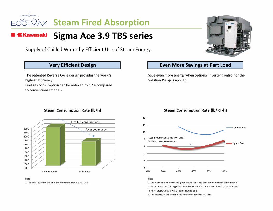
Sigma Ace 3.9 TBS seriesSupply of Chilled Water by Efficient Use of Steam Energy.
The patented Reverse Cycle design provides the world's Save even more energy when optional Inverter Control for thehighest efficiency. Solution Pump is applied.Fuel gas consumption can be reduced by 17% comparedto conventional models:
Note Note
1. The capacity of the chiller in the above simulation is 210 USRT. 1. The width of the curve in the graph shows the range of variation of steam consumption.2. It is assumed that cooling water inlet temp is 89.6ᵒF at 100% load, 80.6ᵒF at 0% load and
it varies proportionally while the load is changing.
3. The capacity of the chiller in the simulation above is 210 USRT.
Very Efficient Design Even More Savings at Part Load
Steam Consumption Rate (lb/h) Steam Consumption Rate (lb/RT-h)
12001300140015001600170018001900200021002200
Conventional Sigma Ace
Less fuel consumption... Saves you money.
5
6
7
8
9
10
11
12
0% 20% 40% 60% 80% 100%
Conventional
Sigma Ace
Less steam consumption and better turn-down ratio.

Steam Fired Absorption
Sigma Ace 3.9 TBS seriesSupply of Chilled Water by Efficient Use of Steam Energy.
Cooling Cycle Steam Supply System
Supplied by PPI Supplied by PPI

Steam Fired AbsorptionSigma Ace 3.9 TBS series
TBS- 80 100 120 150 180 210 250 300 360 400 450 500 560 630 700kW 281 352 422 528 633 739 879 1055 1266 1407 1583 1759 1970 2216 2462RT 80 100 120 150 180 210 250 300 360 400 450 500 560 630 700
Cooling ᵒFFlow Rate gpm 213 266 320 399 479 559 666 799 959 1065 1198 1331 1491 1677 1864Pressure Loss psi 6.4 9.4 5.8 8.6 7.8 10.2 8.7 11.9 9.2 11.1 9.0 10.8 5.8 7.2 9.5Retained Water gal 37 37 48 48 77 77 100 100 137 137 188 188 214 214 238Inlet Temp. ᵒFOutlet Temp. ᵒFFlow Rate gpm 352 440 528 660 793 925 1101 1321 1585 1761 1981 2201 2466 2774 3082Pressure Loss psi 5.7 8.4 9.1 13.4 7.3 9.5 8.3 11.4 8.2 9.9 7.9 9.5 11.7 14.4 18.5Retained Water gal 69 69 92 92 153 153 201 201 283 283 407 407 465 465 515Consumption lb/hr 686 858 1030 1287 1544 1802 2145 2574 3089 3432 3861 4290 4805 5405 6006Inlet Pressure psi
Outlet Temp. ᵒFCapacity KVA 4.1 4.1 5.3 5.3 6.1 6.1 7.5 7.5 8.9 8.9 11.3 11.3 13.9 13.9 14Current A 6.6 6.6 8.3 8.3 9.5 9.5 11.4 11.4 13.5 13.5 17 17 20.8 20.8 20.9Total Motor Power KW 1.3 1.3 2.05 2.05 2.8 2.8 3.6 3.6 4.1 4.1 5.8 5.8 7.6 7.6 7.95
Ch. W. In/Out A 100 100 125 125 150 150 200 200 200 200 200 200 250 250 250Co. W. In/Out A 125 125 125 125 150 150 200 200 250 250 250 250 300 300 300Steam Inlet A 50 50 50 50 65 65 65 65 65 65 100 100 100 100 100Drain Outlet mm 25 25 25 25 32 32 32 32 40 40 50 50 50 50 50Length in 102.1 102.1 144.2 144.2 147.6 147.6 195.9 195.9 196.4 196.4 198.5 198.5 241.8 241.8 265.4Width in 68.7 68.7 68.7 68.7 83.2 83.2 89.3 89.3 102.8 102.8 114.2 114.2 120.4 120.4 125.4Height in 84.1 84.1 84.1 84.1 90.5 90.5 90.5 90.5 97.2 97.2 107.2 107.2 107.6 107.6 107.6Operation Wt. lbs 12544 12544 16128 16128 21952 21952 28224 28224 37408 37408 46816 46816 56224 56224 60256Shipping Wt. lbs 11648 11648 14784 14784 20160 20160 25984 25984 33824 33824 41664 41664 50400 50400 53984
Notes1. Performance tolerance is based on JIS B8622-2002.2. Steam inlet pressure is 114 psi (gauge, saturated) and steam consumption rate is 8.58 lb/RTh.3. The cooling water inlet temperature shall not be lower than 71.6ᵒF.4. The total motor power is the total value of constantly operating motors, excluding purging pump motor which operates intermittently.5. It is required to secure the space for installation of steam control valve, etc. on the top of the chiller. Provide clearance above.5. The maximum operating pressure is 114 psi (gauge) for both Chilled/Hot Water and Cooling Water.6. The fouling factor of both Chilled/Hot Water and Cooling Water is 8.6 x 10⁻⁵ m2 K/W.
Elec
tric
ity 4
00
V 60
HzCo
nnec
tion
Dim
ensio
nsW
eigh
t
194.0> 114
Model
Cooling Capacity
Chill
ed
Wat
er
53.6->44.6
Cool
ingW
ater 89.6
99.0
Stea
m

Interlock WiringSteam Absorption
SymbolsSymbol
CHPCOPCT
ELB Ground Fault BreakerF Fuse
CS Operation SwitchMS Electromagnetic SwitchOCR Overcurrent Relay
X Auxiliary RelayWL Power IndicatorRL Operation IndicatorOL Malfunction Indicator
NameChilled Water PumpCooling Water PumpCooling Tower Fan

Thermal Insulation
80 100 120 150 180 210 250 300 360 400 450 500 560 630 700 830 1000
50 HTG Shell 3.7 3.9 5.4 5.7 6.5 6.7 8.3 8.6 10.5 10.8 12.9 13.1 15.9 16.1 19.3 22.1 26.4Solution Outlet from HTG
Smokebox of HTGLTG Shell
LTG HeaderHeat ExchangerFloating ValveSolution Piping
Refrigerant Vapor PipingRefrigerant Drain Piping
25 Chilled Water Header 1.5 1.5 1.5 1.5 2.4 2.4 2.4 2.4 2.8 2.8 3.5 3.5 3.5 3.5 3.5 4.6 5.7
10Evaporator Shell
Refrigerant Pump 1.7 1.7 2.5 2.5 2.9 2.9 4.2 4.2 4.4 4.4 5.3 5.3 6.6 6.6 7.3 8.1 9.7
Glass Wool (with aluminum foil) 25
Refrigerant Piping Chilled Water Nozzle Refrigerant
Blow Piping 0.8 0.8 0.8 0.8 1 1 1.1 1.1 1.5 1.5 1.6 1.6 1.7 1.7 1.7 2.1 2.4The above values are for the TBG 1.2R series.
Soft Polyurethane Foam
Glass Wool (with aluminum foil)
Heat
Insu
latio
nCo
ld In
sula
tion
PartThicknessMaterial
25 26.4 27.3 29.4 34.6 38.923.58.7 8.7 10.1 10.1 13 13.1 15.4 15.4 19.3 19.3 23.2
Area (m2)
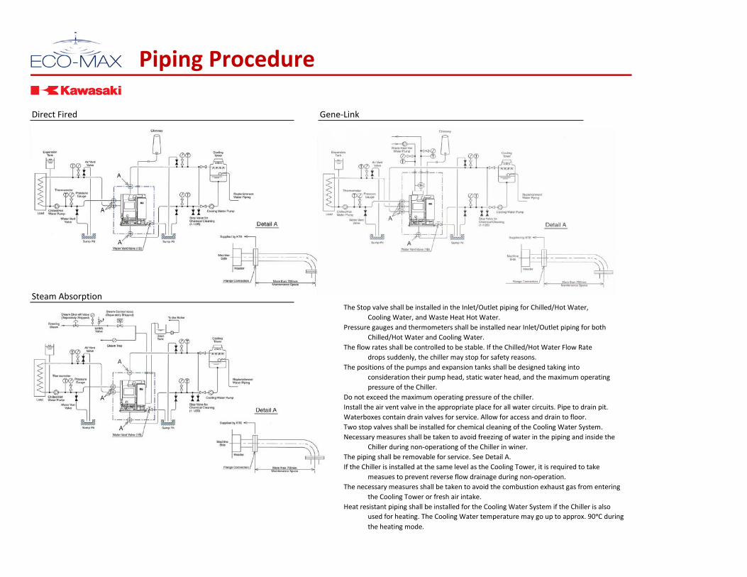
Piping Procedure
Direct Fired Gene-Link
Steam AbsorptionThe Stop valve shall be installed in the Inlet/Outlet piping for Chilled/Hot Water,
Cooling Water, and Waste Heat Hot Water.Pressure gauges and thermometers shall be installed near Inlet/Outlet piping for both
Chilled/Hot Water and Cooling Water.The flow rates shall be controlled to be stable. If the Chilled/Hot Water Flow Rate
drops suddenly, the chiller may stop for safety reasons.The positions of the pumps and expansion tanks shall be designed taking into
consideration their pump head, static water head, and the maximum operatingpressure of the Chiller.
Do not exceed the maximum operating pressure of the chiller.Install the air vent valve in the appropriate place for all water circuits. Pipe to drain pit.Waterboxes contain drain valves for service. Allow for access and drain to floor.Two stop valves shall be installed for chemical cleaning of the Cooling Water System.Necessary measures shall be taken to avoid freezing of water in the piping and inside the
Chiller during non-operationg of the Chiller in winer.The piping shall be removable for service. See Detail A.If the Chiller is installed at the same level as the Cooling Tower, it is required to take
measues to prevent reverse flow drainage during non-operation.The necessary measures shall be taken to avoid the combustion exhaust gas from entering
the Cooling Tower or fresh air intake.Heat resistant piping shall be installed for the Cooling Water System if the Chiller is also
used for heating. The Cooling Water temperature may go up to approx. 90ᵒC duringthe heating mode.
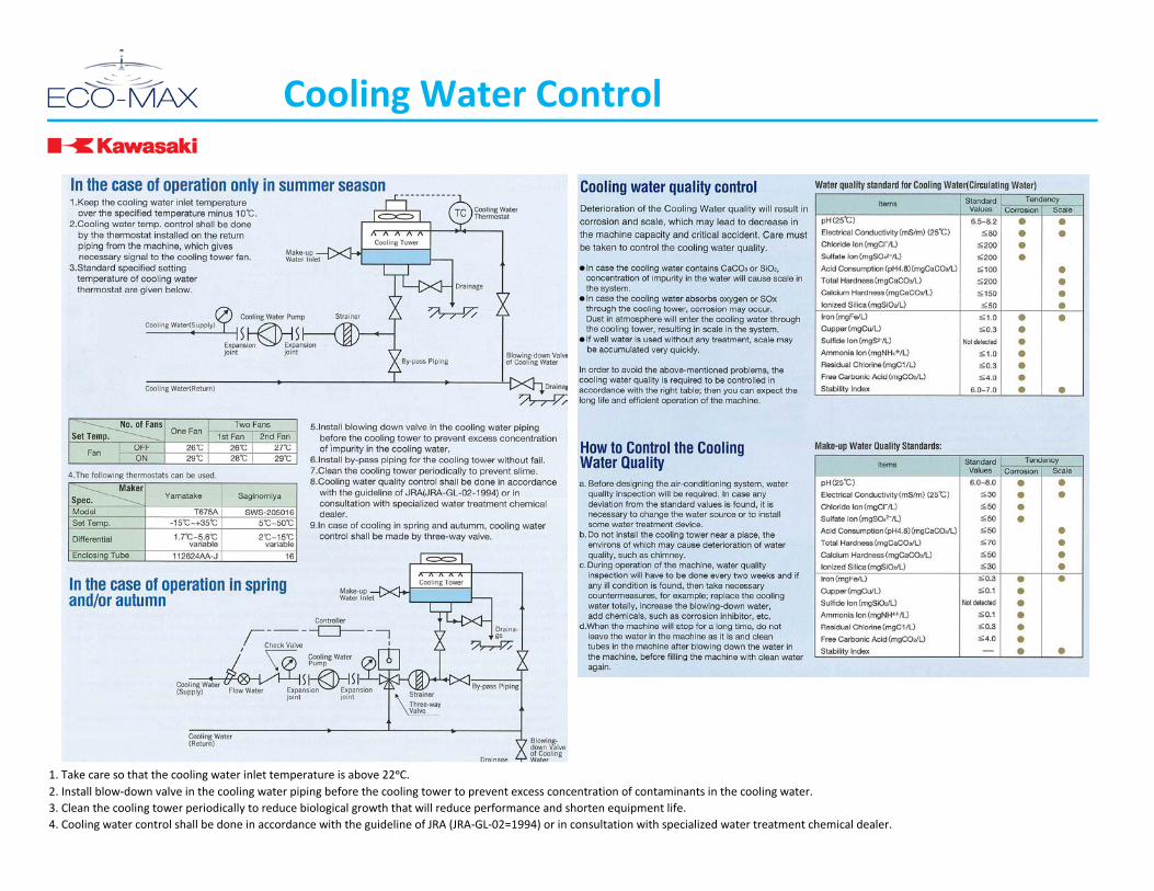
Cooling Water Control
1. Take care so that the cooling water inlet temperature is above 22ᵒC.2. Install blow-down valve in the cooling water piping before the cooling tower to prevent excess concentration of contaminants in the cooling water.3. Clean the cooling tower periodically to reduce biological growth that will reduce performance and shorten equipment life.4. Cooling water control shall be done in accordance with the guideline of JRA (JRA-GL-02=1994) or in consultation with specialized water treatment chemical dealer.