abstract- aerodynamic characteristics of a honda civic car ... · using ansys . g.ganesh,...
TRANSCRIPT

International Journal of Scientific & Engineering Research, Volume 6, Issue 6, June-2015 762 ISSN 2229-5518
IJSER © 2015 http://www.ijser.org
Analysis of Effects of Rear Spoiler in Automobile Using Ansys
G.Ganesh, Mechanical Engineering Department, Kingston Engineering College, Vellore V.Vasudevan, Assistant Professor, Mechanical Engineering College, Kingston Engineering College, Vellore
Abstract- Aerodynamic characteristics of a Honda civic car 2009 are of significant interest in reducing car-racing accidents due to wind loading and in reducing the fuel consumption. Even though these vehicles typically have a more rigid chassis and a stiffer suspension to aid in high-speed maneuverability, a spoiler can still be beneficial. One of the design goals of a spoiler is to reduce drag and increase fuel efficiency. Many vehicles have a fairly steep downward angle going from the rear edge of the roof down to the trunk or tail of the car. Reducing flow separation decreases drag, which increases fuel economy; it also helps keep the rear window clear because the air flows smoothly through the rear window.
This thesis will present a numerical simulation of flow around racing car with spoiler positioned at the rear end using commercial Autodesk flow design software. The thesis will focus on CFD-based lift and drag prediction on the car body after the spoiler is mounted at the rear edge of the vehicle. A 3D computer model of 4-door sedan car (which will be designed with commercial software SolidWorks) will be used as the base model. Different spoilers, in different locations will be positioned at the rear end of vehicle and the simulation will be run in order to determine the aerodynamic effects of spoiler.
I INTRODUCTION
When a driver drives his or her car in high speed condition, especially at highway which is speed limit 110 km/h, the car has high tendency to lift over. This is possible to happen because as the higher pressure air in front of the windshield travels over the windshield; it accelerates, causing the pressure to drop. This lower pressure literally lifts on the car’s roof as the air passes over it. Worse still, once the air makes its way to rear window, the notch created by the window dropping down to the trunk leaves a vacuum or lower pressure space that the air is not able to fill properly.
The flow is said to detach and the resulting lower pressure creates lift that then acts upon the surface area of the trunk. To reduce lift that acted on the rear trunk, a rear spoiler can attach on it to create more high pressure. Spoilers are used primarily on sedan-type cars. They act like barriers to air flow, in order to build up higher air pressure in front of the spoiler. This is useful, because as mentioned previously, a sedan car tends to become "Light" in the rear end as the low pressure area above the trunk lifts the rear end of the car.
2 METHODOLOGY & APPROACH OF THE WORK
In this work, first of all a generic model of the passenger car is prepared in the SOLIDWORKS software and this generic model is import into the AUTODESK Flow design software to do the simulation of the coefficient of drag and coefficient of lift in the wind tunnel which is generated in the design module of the AUTODESK Flow design software. After this the meshing is generated on the surface of the passenger car.
Aerodynamic evaluation of air flow over an object
can be performed using analytical method or CFD approach. On one hand, analytical method of solving air flow over an object can be done only for simple flows over simple geometries like laminar flow over a flat plate. If air flow gets complex as in flows over a bluff body, the flow becomes turbulent and it is impossible to solve Navier- Stokes and continuity equations analytically. On the other hand, obtaining direct numerical solution of Navier-stoke equation is not yet possible even with modern day computers. In order to come up with reasonable solution, a time averaged Navier-Stokes equation is being used (Reynolds Averaged Navier-Stokes Equations – RANS equations) together with turbulent models to resolve the issue involving Reynolds Stress resulting from the time averaging process.
In present work the k-e turbulence model with
non-equilibrium wall function is selected to analyze the flow over the generic passenger car model. This k-e turbulence model is very robust, having reasonable computational turnaround time, and widely used by the auto industry. 3 CAD MODEL
The models of both vehicle and two different spoilers have been 3D printed using the software called SolidWorks to CAD format for numerical analysis.Then after, this model has been analysed for drag coefficient and forces under the AUTODESK Flow design module and values of drag coefficient, lift coefficient.
IJSER

International Journal of Scientific & Engineering Research, Volume 6, Issue 6, June-2015 763 ISSN 2229-5518
IJSER © 2015 http://www.ijser.org
Figure 1 Vehicle 3D CAD model 4 MESH GENERAION
The triangular shape surface mesh was used due to its proximity to changing curves and bends. These elements easily adjust to the complex bodies used in automobile and aerospace bodies. With the default settings for mesh generation, ANSYS Meshing has generated the meshes as seen in Figure 2.
Figure 2 Mesh generation with standard settings
5 VEHICLE AND THE SPOILER
5.1 INTRODUCTION TO SPOILER
A spoiler is an automotive aerodynamic device whose intended design function is to “spoil” unfavorable air movement across a body of a vehicle in motion, usually described as drag. Spoilers on the front of a vehicle are often called air dams, because in addition to directing airflow they also reduce the amount of air flowing underneath the vehicle, which generally reduces aerodynamic lift and drag. Spoilers are often fitted to race and high-performance sports cars, although they have become common on passenger vehicles as well. Some spoilers are added to cars primarily for styling purposes and have either little aerodynamic benefit or even make the aerodynamics worse.
The goal of many spoilers used in passenger vehicles is to reduce drag and increase fuel efficiency. Passenger vehicles can be equipped with front and rear spoilers. Front spoilers, found beneath the bumper, are mainly used to decrease the amount of air 19 going underneath the vehicle to reduce the drag coefficient and lift. Sports cars are most commonly seen with front and rear spoilers. This is because many vehicles have a fairly steep downward angle going from the rear edge of the roof down to the trunk or tail of the car, which may cause airflow separation. The flow of air becomes turbulent and a low-pressure zone is created, increasing drag and instability. Adding a rear spoiler could be considered as making the air "see" a longer, gentler slope from the roof to the spoiler, which helps to delay flow separation and the higher pressure in front of the spoiler can help reduce the lift on the car by creating down force. This may reduce drag in certain instances and will generally increase high-speed stability due to the reduced rear lift. Due to their association with racing, consumers often view spoilers as sporty. 6 GENERIC MODELS
6.1 Vehicle generic models and dimensions
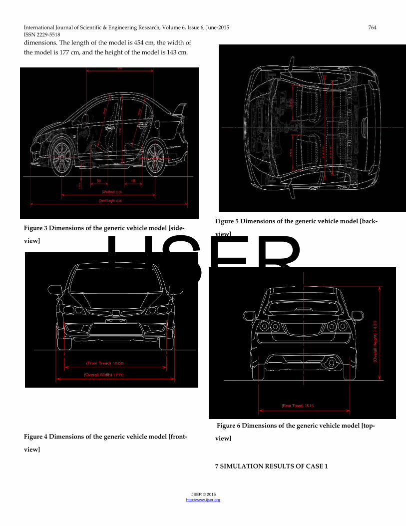
The Generic model of the vehicle is shown in Figure 3, Figure 4 and Figure 5 below with relevant
IJSER
International Journal of Scientific & Engineering Research, Volume 6, Issue 6, June-2015 764 ISSN 2229-5518
IJSER © 2015 http://www.ijser.org
dimensions. The length of the model is 454 cm, the width of the model is 177 cm, and the height of the model is 143 cm.
Figure 3 Dimensions of the generic vehicle model [side-
view]
Figure 4 Dimensions of the generic vehicle model [front-
view]
Figure 5 Dimensions of the generic vehicle model [back-
view]
Figure 6 Dimensions of the generic vehicle model [top-
view]
7 SIMULATION RESULTS OF CASE 1
IJSER

International Journal of Scientific & Engineering Research, Volume 6, Issue 6, June-2015 765 ISSN 2229-5518
IJSER © 2015 http://www.ijser.org
A 3D steady state, incompressible solution of the Navier-Stokes equations was performed using AUTODESK Flow design software. Turbulence modeling was done with the realizable k-ε model using non- equilibrium wall functions. The computational results for the following case was presented and discussed: Case 1- Vehicle model without rear spoiler All the results for different cases were obtained with the same meshing resolution, the same k − ε turbulence model, and also the same boundary conditions. The free stream velocity was set to be 25m/s. For the first 100 iterations, a first order upwind discretization was used to accelerate the convergence then after 100 iterations second order upwind scheme has been applied and iterations have continued until it reached to the convergence criteria. The convergence history of drag coefficient of case #1 as shows in Figure 7.
Figure 7 Drag coefficient (CD) convergence history of case 1
8 SIMULATION RESULTS OF CASE 2
A 3D steady state, incompressible solution of the Navier-Stokes equations was performed using AUTODESK Flow design software. Turbulence modeling was done with the realizable k-ε model using non- equilibrium wall functions. The computational results for the following case was presented and discussed: Case 2- Vehicle model with rear-spoiler All the results for different cases were obtained with the same meshing resolution, the same k − ε turbulence model, and also the same boundary conditions. The free stream velocity was set to be 25m/s. For the first 100 iterations, a first order upwind discretization was used to accelerate the convergence then after 100 iterations second order upwind scheme has been applied and iterations have continued until it reached to the convergence criteria. The convergence history of drag coefficient of case 2 as shows in Figure 8.
Figure 8 Drag coefficient (CD) convergence history of case 2
9 CONCLUSION
IJSER
International Journal of Scientific & Engineering Research, Volume 6, Issue 6, June-2015 766 ISSN 2229-5518
IJSER © 2015 http://www.ijser.org
Modeling of Honda Civic R 2009 is done using
Solidworks. Analysis of effects of rear spoiler in automobile is done using AUTODESK flow design software. The Modeling and analysis of Honda Civic R 2009 car without rear spoiler and the CD (Co efficient of drag=0.28) was calculated. The Modeling and analysis of Honda Civic R 2009 car with rear spoiler and the CD (Co efficient of drag=0.21) was calculated. 10 REFERENCES
1 R. B. Sharma, Ram Bansal CFD Simulation for Flow over Passenger Car Using Tail Plates for Aerodynamic Drag Reduction. (5, Jul. - Aug. 2013).
2 R. B. Sharma, Ram Bansal Drag and lift reduction on passenger car with rear spoiler. (3, Aug 2013).
3 Xu-xia Hu, Eric T.T. Wong A Numerical Study On Rear-spoiler Of Passenger Vehicle. (5,July 2011).
4 Shyam p. Kodali, srinivas bezavada Numerical simulation of air flow over a passenger car and the Influence of rear spoiler using CFD. ( 01, Jan-Dec 2012).
5 John J. Bertin, “Aerodynamics for Engineers”, Prentice Hall; 5th edition, New Jersey, June 2008.
6 Website:http://autospeed.com/cms/titleAero-Testing-Part-4/A_108676/article.html.
IJSER