abstract - École polytechnique fédérale de lausanne · lab oratories. in the last decade, ......
TRANSCRIPT

POLITECNICO FEDERALE DI LOSANNASWISS FEDERAL INSTITUTE OF TECHNOLOGY LAUSANNE
�ECOLE POLYTECHNIQUEF�ED�ERALE DE LAUSANNECommunication Systems Division (SSC)
EPFL CH-1015 Lausanne, Switzerlandhttp://sscwww.ep .ch
Remote Inspection of Medical Images
through High-speed Networks
Ra�aele Noro and Jean-Pierre Hubaux, EPFL-DE-TCOM
July 1997
Technical Report SSC/1997/018

CONTENTS 1
Contents
I. A Multimedia Architecture for Medical Tele-Imaging over
ATM 1
1 Introduction 1
2 Dynamic medical image inspection 3
3 Image Data organization and storage 4
4 Real-time Dynamic Image Inspection 4
4.1 Slice selection . . . . . . . . . . . . . . . . . . . . . . . . . . . 44.2 Stream generator . . . . . . . . . . . . . . . . . . . . . . . . . 44.3 Stream control . . . . . . . . . . . . . . . . . . . . . . . . . . 54.4 System encoder and decoder . . . . . . . . . . . . . . . . . . . 54.5 Network adaptation . . . . . . . . . . . . . . . . . . . . . . . 54.6 Video decoder . . . . . . . . . . . . . . . . . . . . . . . . . . . 54.7 Mouse Stream generation, formatting and handling . . . . . . 5
5 Future Developments 6
6 Conclusion 6
II. Real Time Telediagnosis of Radiological Images through ATM
network: the ARTeMeD Project 8
1 Introduction 8
2 System architecture 9
3 The architecture components 11
4 Medical image storage, access and retrieval in ARTeMeD
systems 13
4.1 Storage in the database . . . . . . . . . . . . . . . . . . . . . 134.2 Access of target images in the database . . . . . . . . . . . . 134.3 Retrieval of images: the user interface . . . . . . . . . . . . . 14
5 Prototyping of an ARTeMeD system: implementation and
performances 15
6 Comparison with other systems 16
7 Conclusion and further work 16

Abstract
In health care practice, diagnosis and therapy tasks are founded on theanalysis of medical images. Traditionally, such analysis was performed usingoptical devices like light boxes or microscopes installed in clinical rooms orlaboratories. In the last decade, personal computers have revolutioned thispractice and today medical imaging is based on soft-copies of image materialrather than �lms or specimens. Acquisition, storage and display of medicalimages are performed through digital computers and/or workstations. Morerecently, the introduction of networked computers has lead to the conceptof telemedicine, that is making available remote medical facilities throughthe use of personal computers and digital networks.
In this document we analyse the problem of real-time performance intelemedicine applications and we propose a new architecture that allows theinteractive and real-time exchange of medical images. This architecture isbased on a hierarchical database to store images, an high-speed network totransmit images and a navigation module allowing the user to dynamicallyselect the portion and resolution of the images under inspection.
In the second part of the document we describe, in particular, the pro-totype developed according to the described architecture and we discussperformance and optimization aspects.
Keywords: Telemedicine, Client-server architecture, Hierarchical database.

R.Noro J.-P.Hubaux: Remote Inspection of Medical Images 1
A Multimedia Architecture for Medical
Tele-Imaging over ATM
A.Basso, O.Verscheure, J.P.Hubaux, R.NoroTelecommunications Services Group TCOM Ecole Polytechnique
F�ed�erale de Lausanne,
R.Meuli, R.Laurini, R.PattheyCentre Hospitalier Universitarie Canton Vaud, Institut de Radiologie
Abstract
The goal of this paper is to present a multi-media telecommu-nication architecture based on ATM technology, which provides re-liable and e�ective transmission of still and motion high resolution(1024x1024 up to 4096x4096, 16 or 32 bits/pixel) radiological andpathological images or part of them.
The peculiarities of such architecture are the following.
� Provide Quality of Service (QoS) awareness by means of interand intra ow synchronization mechanisms.
� Provide mechanisms of reliable transmission of data.
� Provide the capability of remote manipulation of a Region ofInterest (RoI), de�ned as a portion of a still or motion picturewhich is represented and coded with a higher quality than theremaining part of the picture.
1 Introduction
In the last decade the communication networks have had an enormous de-velopment both in local area networks (LAN) and in wide area networks(WAN). Recently a new mode of data transfer called asynchronous transfer
mode (ATM) [1], suitable for very fast packet switching and with Qualityof Service (QoS) guarantee has been developed. Such technique relies onlarge bandwidths (of the order of tenths and hundredth of Mbits/s) andallows a reliable transmission of real-time streams such as video and audiodata, typical of multimedia applications. From an application point of viewthe navigation and the consultation of information stored in remote sites ismade possible by means of well known and largely employed browsers suchas the World Wide Web. Furthermore important progress has been done inthe domain of the cooperative work.

R.Noro J.-P.Hubaux: Remote Inspection of Medical Images 2
The medical community is showing great interest for this evolution inthe area of multimedia communications: a signi�cative number of hospitalsare already equipped with local ATM networks. At the same time a largenumber of servers make available important medical databases, in particularmedical still and motion pictures. Finally the evolution of the production ofelectronic chips such as microprocessors makes the price of a quite powerfulcomputer accessible to a large number of people.
The real-time transmission and processing of medical image data be-comes today possible, opening interesting possibilities in particular in thearea of the tele-diagnosis.
In this paper we propose a telecommunication multi-media architecturebased on ATM technology, which provides reliable transmission of still highresolution (1024x1024 up to 4096x4096, 16 or 32 bits/pixel) radiological andpathological images or part of them. The peculiarities of such architectureare the following:
� provide Quality of Service (QoS) awareness. Inter and intra ow syn-chronization mechanisms assure a natural event synchronization
� provide mechanisms of reliable transmission of data. Proper packetiza-tion mechanisms assure system robustness against network errors, suchas cell losses and cell delay variations.
� provide the capability of remote manipulation of a Region of Interest(RoI) called also detail image, de�ned as a portion of a still or motionpicture which is represented and coded with a higher visual qualitythan the remaining part of the picture.
MonR2MonR1
MonL1 MonL2
ATM
Site 1
Site 2
Video Conference
Video ConferenceMedical Images
Medical Images
MonL1, MonR1: Teleconference + Overview
MonL2, MonR2: Medical Image Display
SERVER
CLIENT
Fig. 1: A typical application scenario: MonRi, MonLi represent the monitorsavailable at each site
A typical scenario is shown in Fig. 1. Two remote sites are interconnectedby an ATM network. Each site has the following functionalities:
� Teleconferencing: the teleconferencing tool is based on a commercialproduct and is able to assure a reliable teleconferencing session betweenthe two operators. It is capable of MPEG-1 video and audio coding aswell as white board sharing.

R.Noro J.-P.Hubaux: Remote Inspection of Medical Images 3
� Access and inspection of medical images. Images are stored in an imagedatabase in which radiological and pathological high de�nition images(around 4000 dpi) are stored. Images can be accessed and inspected inreal time without previous image �le transmission.
The image inspection is performed by means of two windows. A �rstwindow, called overview, displays the image under inspection at low reso-lution. On such overview it is possible to dynamically displace a resizablerectangle to select a part of the image for detailed inspection. This sub-image is called detail image or Region of Interest (RoI). The detail imageis displayed in a second window which is updated in real time (max speed25 frames per second) according to the displacement of the selection rectan-gle on the overview. Image inspection is assisted by a teleconferencing toolwhich allows the two operators to interact and to cooperatively perform theanalysis of the medical image.
2 Dynamic medical image inspection
The system architecture is presented in more detail in Fig. 2. A serverprovides the ows associated with the detail image. The client gets this owand supplies the user with the position of the mouse and the dimensions ofthe detail image. The network support is based on ATM technology, withbandwidth of 34 Mbits/sec. The system sub-blocks are described in detailin the following sections.
Filtering
process
Post
Video
decoder
decoder
System
CLIENT
b
c
aformat
Stream
size
Window
adaptation
Network
Mouse
position
imageOverview Detail
c
b
a
c
flow : mouse position indication
flow : downsampling of original image
SERVER
c flow : detailed image
b
type
a
Window
Mouse
type
type
ATM Network
sampling
Functionality panel
database
Down
Network
adaptation
encoder
Image
imageOriginal
coderOff-line
indexingSlice
selection
Slice
controlStream
generator
SystemStream
7
6
5
4
32
.....
size
tracking
1
Fig. 2: Block diagram of the architecture

R.Noro J.-P.Hubaux: Remote Inspection of Medical Images 4
3 Image Data organization and storage
Each image is stored in the database in two di�erent formats:
� subsampled: typically a subsampling factor of 4 in each spatial di-mension is used. Less than 32 bits per pixels are used. The exactsubsampling factor and number of bits per pixel depend on the imagetype. This is the format of the overview image.
� JPEG-like o�-line encoded and organized in slices of �xed size (80x16pixels).
An o�-line indexing process labels each slice according to its positionon the original image as shown in Fig. 2. The advantages of such datarepresentation are the following.
� It allows a fast access to di�erent parts of the image by di�erent users.
� The coding is performed only once allowing a full software architecturewithout the need of a hardware encoder.
� The visual quality of the sequence of images generated by dynamicdisplacement of the reseizable rectangle on the overview is constantbecause the encoding process is performed only once. The operatorhas full control of the visual quality of the sequence at encoding stage.The JPEG coding method has been employed because it is the onlycompression method validated by the radiologic community [2].
4 Real-time Dynamic Image Inspection
4.1 Slice selection
The mouse position and the rectangle dimensions on the overview image areupdated for each mouse displacement and are taken as input for the sliceselection on the server side.
4.2 Stream generator
The selected slices are then encapsulated in a video stream by the streamgenerator. Proper headers (sequence headers, GOP headers, picture head-ers) are added in order to form an MPEG-2 compliant stream. This MPEG-2stream is composed by only I-frames, assuring a constant visual quality. Asan example, for a detail window of 512x512 pixels, 16 bits/pixel at 25 framesper second, with a compression rate of 10, the bitrate is around 10Mb=s.The stream generator is under the control of a stream controller which isdiscussed hereafter.

R.Noro J.-P.Hubaux: Remote Inspection of Medical Images 5
4.3 Stream control
The stream controller performs a regulation on the stream generator. Ittakes as input the mouse tracked position and determines whether or not togenerate and send the video stream. If the mouse is not moving for a giveninterval of time, the detail image is still, thus transmission is not needed. Inthat case, the stream generation and packetization are suspended.
Finally the elementary video stream is mapped to ATM by the systemencoder in a similar way as speci�ed by the ATM Forum and ITU [3, 4, 5].
4.4 System encoder and decoder
The system encoder creates an MPEG-2 [6] compliant Transport Stream(TS) [7] taking as input the video stream. The output is a sequence of 188bytes long TS packets. The system decoder performs the inverse operationat the receiving end.
4.5 Network adaptation
The Network adaptation block maps incoming TS packets (188 bytes) intooutgoing AAL-5 PDU packets (376 bytes).The inverse operation is per-formed at the receiving end.
4.6 Video decoder
One of the advantages of formatting the image material on an MPEG-2compliant video stream is that it can be decoded with a standard MPEG-2 video decoder. In the case of slow mouse movements software video de-coder can give satisfactorily performances if su�cient computation power isavailable. Best performances may be obtained using a hardware MPEG-2video decoder.
4.7 Mouse Stream generation, formatting and handling
The mouse position is sampled on the overview image and mapped in thecorresponding position in the high de�nition image.
There are three components for each sample: 2 spatial coordinates and1 temporal coordinate (time stamp). Time stamps have the role to keep this ow synchronized with the video.
An error concealment method at the receiver end is used to recover frommouse position losses, which can be very annoying. It is based on mousespeed and acceleration estimation.
R.Noro J.-P.Hubaux: Remote Inspection of Medical Images 6
Site 2
Video Conference
Medical Images CLIENT MonV2 MonI2
Video ConferenceSERVER
Medical ImagesSite 1
ATM
Medical Images CLIENT
Video Conference
Site 3
Video Conference
Medical Images CLIENT
Site 4
MonV1 MonI1
MonV3 MonI3 MonV4 MonI4
MonV1..,MonVN: Teleconference + Overview
MonI1, ..MonRN: Medical Image Display
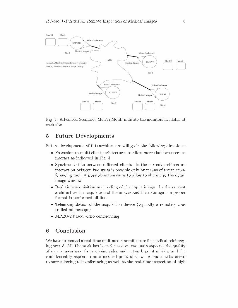
Fig. 3: Advanced Scenario: MonVi,MonIi indicate the monitors available ateach site
5 Future Developments
Future developments of this architecture will go in the following directions:
� Extension to multi client architecture: to allow more that two users tointeract as indicated in Fig. 3.
� Synchronization between di�erent clients. In the current architectureinteraction between two users is possible only by means of the telecon-ferencing tool. A possible extension is to allow to share also the detailimage window.
� Real time acquisition and coding of the input image. In the currentarchitecture the acquisition of the images and their storage in a properformat is performed o�-line.
� Telemanipulation of the acquisition device (typically a remotely con-trolled microscope).
� MPEG-2 based video conferencing.
6 Conclusion
We have presented a real-time multimedia architecture for medical teleimag-ing over ATM. The work has been focused on two main aspects: the qualityof service awarness, from a joint video and network point of view and thecon�dentiality aspect, from a medical point of view. A multimedia archi-tecture allowing teleconferencing as well as the real-time inspection of high

R.Noro J.-P.Hubaux: Remote Inspection of Medical Images 7
resolution medical images has been discussed. Future development of sucharchitecture are foreseen, which will allow an extension to more users andimproved handling of the Region of Interest.

R.Noro J.-P.Hubaux: Remote Inspection of Medical Images 8
Real Time Telediagnosis of Radiological Images
through ATM network: the ARTeMeD Project.
R.Noro, J.P.HubauxTelecommunications Services Group TCOM Ecole Polytechnique
F�ed�erale de Lausanne,
R.Meuli, R.Laurini, R.PattheyCentre Hospitalier Universitarie Canton Vaud, Institut de Radiologie
Abstract
The ARTeMeD project aims to solve problems of interactivity and real-time in
teleradiology. It integrates personal multimedia facilities and patient data access in
a common platform that allow radiologists to collaborate from remote sites through
a suitable communication support. ARTeMeD is based on ATM network technology
and an optimized manipulation of medical image material. The ARTeMeD system
opens interesting perspectives in the area of collaborative teleradiology.
1 Introduction
In this article we describe theATM Real-Time Medical Diagnosis (ARTeMeD)project under way in Lausanne at the Telecommunications Laboratory of theEPFL and the University Hospital. In this project we are exploring solutionsin telemedicine [8] that allow interactive, real-time remote diagnosis both inpathology and in radiology. To contribute e�ectively in this area, we anal-ysed existing systems and identi�ed ways of improving their performance.The project involves studying how medical image processing maps onto anetwork technology; the fast transmission of high resolution images, the ca-pability of remote manipulation of Region of Interest (RoI), that is a userselected portion of an image with high perceptual quality and/or resolutionand the live audio and video communication are addressed in ARTeMeD,as well as the synchronization requirements and the multi-party support forcollaborative work.
The results of the project include an architecture, the ARTeMeD system,which englobes the aforementioned aspects. The key issues of ARTeMeD arethe optimization of storage, access and retrieval of medical images, the useof high-speed networking technology and the deployment of suitable imagecompression algorithms.

R.Noro J.-P.Hubaux: Remote Inspection of Medical Images 9
The paper is organized as follows. In sections 2 and 3 we describe thearchitecture. In section 4 the organization and manipulation of medicalimage material is detailed. In sections 5 and 6 we present our prototypeimplementation, performance measures and a comparison to a pre-existingstandard solution for teleradiology. Some conclusions and suggestions forfurther work are discussed at the end of the paper.
2 System architecture
The ARTeMeD project has evolved by taking into account the needs forreal-time and interactivity in teleradiology: these needs have been analyzedin terms of system requirements and system design. The resulting architec-ture is an integration of desktop conferencing facilities and a new methodfor storage/retrieval of medical images over a suitable communication sup-port, as indicated in Fig. 1. The communication support considered here isbased on Asynchronous Transfer Mode (ATM) network technology [9]. Thisparticular subsystem provides two access points to the application level:one for the exchange of medical data and one for the multimedia personalcommunication.
Real time communication support:- transmission of medical images
- transport of audio-video streams- transmission of user requests
UserARTeMeDsystem
Desktop conferencing:- personal communication
- video connections- audio connections
Medical data echange:- sharing of images- access to database- browsing- navigation- user interface
Fig. 1: Integration of desktop conferencing and medical data exchange overcommunication support for ARTeMeD.
A typical scenario in which our system can be used is composed as fol-lows: images are stored in a server and one or more radiologists want toaccess and browse the images on their screen. Collaboration of radiologistover the same subject is allowed: in this case, the same images are dis-tributed by the server to the participants of the session. The conferencingsubsystem interconnects all the participants. At a given time, only one radi-ologist has control over the images: his interactions with the server produce

R.Noro J.-P.Hubaux: Remote Inspection of Medical Images 10
the images that are distributed. Such a situation is sketched in Fig. 2 forthe case of two radiologists.
Communication support
User A
Client A Server
User B
Client B
Control of imagesone-to-one
Medical imagesone-to-many
Conferencemany-to-many
Exchangeof medicaldata
Exchangeof medicaldata
of medicalExchange
data
Conferencing
Conferencing
Fig. 2: Two users cooperating on the same medical subject.
It is worth noticing that the control of images ows from one client tothe server (one-to-one connection), images ow from server to all the clients(one-to-many) and conferencing interconnects each client with each client(many-to-many).
The contribution of the ARTeMeD project is mainly in the medicalpart: we propose an innovative client-server approach for optimizing theretrieval and display operation times of medical high-resolution, still im-ages. ARTeMeD allows interactivity and real-time thanks to the followingdesign features:
� reduced amount of data to be processed, thanks to the compression andhierarchical organization of images,
� increased transfer rate for the communication support, thanks to theATM network technology,
� a simple graphical interface for the navigation of the medical images,thanks to the concept of user-de�ned RoI.
Some additional requirements must also be satis�ed for the e�cient co-operation among specialists: the latency of the system must be kept undercontrol (that is, the time between the generation of a request by the userand the display of the requested image on the users' screens) as well as thecoordinated presentation of the same images in spatially separated sites.These two aspects are often referred to as temporal and spatial synchro-
nization [10, 11] and are fundamental to allow interactivity in distributedenvironments; they are taken into account for the ARTeMeD project.

R.Noro J.-P.Hubaux: Remote Inspection of Medical Images 11
3 The architecture components
Any ARTeMeD session is opened with one ARTeMeD server and one or moreARTeMeD clients. The client is expected to o�er an interface to the radiolo-gist, while the server is designed to inteface with the medical data stored inan attached database and also to perform some centralized activities (amongothers, monitoring of the participants and spatial synchronization tasks).
The basic components used to build both the server and the client of theARTeMeD system are represented in Fig. 3. The blocks labelled with 1, 2,3 and 4 belong to the medical data exchange subsystem; the blocks 5, 6, 7and 8 to the conferencing subsystem and the blocks 9 and 10 constitute thecommunication subsystem.
Block 4 - capture of user’ requests
Userinterface
Conference:Block 5 - audio inBlock 6 - audio outBlock 7 - video inBlock 8 - video out
Client A
Block 9: adaptation to communication
Medical exchangeBlock 1 - decoding and displayBlock 2 - user control
Block 9: adaptation to communication
Conference:
Block 8 - video outBlock 7 - video in
Block 5 - audio inBlock 6 - audio out
Client B
Medical exchangeBlock 1 - decoding and displayBlock 2 - user control
Server
Medical exchange
Block 10
infrastructurecommunication
Block 3 - access, retrieval andencoding
Fig. 3: ARTeMeD system components.
Block 1: decoding and display. Each ARTeMeD client is equipped withthis block: it is designed to get compressed image data from the network,to process this information and to display the target image on the user'sscreen.
Block 2: user control and graphical interface. In the ARTEMeDclient, this functional block provides the capability to the user to performsome remote actions on the server. The user actions (e.g., the de�nition of aRoI, the selection of a low resolution image to be magni�ed, the modi�cation

R.Noro J.-P.Hubaux: Remote Inspection of Medical Images 12
of grey windows) are captured by this block and mapped onto messages tobe carried over the communication support.
Block 3: user commands interpretation and database request.
This block is situated in the ARTeMeD server: it transforms the incom-ing user message from the network (generated by the Block 2) into a �lterfor the selection of images and/or portion of them to be retrieved in thedatabase.
Block 4: access, retrieval and encoding. The selection required by theBlock 3 is performed by the current block and the image data is generatedin the format required by the Block 1. Block 4 operates on the compressedimages: it must supply output data that correspond to the speci�ed com-pressed format, but implementation can be done in several, independentmanners.
Blocks 5, 6, 7 and 8: compression and rendering of audio-video
streams. Audio-visual interconnections between participants are obtainedby means of these blocks: they perform the two way mapping between audioand video frames and network packets. Their functionalities are out of thescope of the ARTeMeD project, which simply integrates them beside themedical imaging part. It is worth to notice that video communication canbe optionally dropped from the setup with a reduced impact on the degree ofinteractivity of the system (if, for instance, a camera is not available or theaudio quality is good enough or we can save bandwith/CPU for the medicalexchange and so on).
Block 9: communication interface and adaptation. This block in-terfaces each user terminal with the communication support. It has twomain tasks: �rst, it deals with etherogenity in the communication support(for instance, the host running the server can run at the same time a clientand interconnection happens on the internal bus and not on network) andsecond handles the paths along which data are sent (all the client-to-client,client-to-server and server-to-client connections).
Block 10: communication infrastructure. This is one of the crucialcomponents of the system. It must have a powerful and exible commu-nication infrastucture to support the information ow generated by such asystem: high amount of data to be moved with strong temporal constraints.For this speci�c reason, ATM is at the moment the more suitable technol-ogy to do so. Nevertheless, in a LAN environment (for instance an hospitalnetwork), other technologies (e.g. Ethernet or Fast-Ethernet) can be ap-

R.Noro J.-P.Hubaux: Remote Inspection of Medical Images 13
propriated, but as soon as we consider a more spread system it becomesprohibitive to obtain the same results with classical network technologies.
4 Medical image storage, access and retrieval in
ARTeMeD systems
Our approach for the manipulation of radiological images in ARTeMeD isorganized into steps: the storage in the server's disk or database is performedo�-line, directly from the acquisition device. The access and retrieval of thestored material is done on user request and is performed in real-time duringthe operative session. It is important to notice that the ARTeMeD systemis based on a completely �le transfer-free paradigm: the requested imagesdo not need to be stored in the client's disk. Instead, they are processedby the decoding block and directly browsed on the user's screen. They costmemory, but no extra disk space. The images do not leave the server's disk,they are just displayed, through a compression/decompression middlelayer,onto the client's screen giving the impression of manipulating a local copy.The remainder of this section describes the storage, access and retrievalphases of our system, that is, the most original part of ARTeMeD.
4.1 Storage in the database
The images coming from the acquisition device (CT, MRI) are pre-processed:they are organized in a hierarchy of resolution levels for the following accessand retrieval phases. Two (or possibly three) subsampling operations of thehigh resolution images are performed and the di�erent levels of resolutionare obtained (Fig. 4). Then, for each level, all images are disposed in agallery . The so obtained galleries are logically splitted in elementary regionswhich are the quanta of information for the access and retrieval phases. Acompression algorithm is applied to the images in the hierarchy, reducing theamount of information to be transferred. In our implementation, the MPEG-2 standard have been choosen: the elementary regions just mentioned are theslices of the MPEG algorithm [12]. Compressed slices are indexed, in orderto allow the fast access to speci�ed portions of the images in the followingphases.
4.2 Access of target images in the database
The user can specify which image(s) and resolution he wants (e.g., the coars-est gallery or overview gallery , a part of the semi-full resolution gallery, asingle image at the highest resolution). Through his graphical interface, hesends a request to the server in the form of a geometrical area of an im-age and the corresponding resolution level. This request acts like a �lterover the slice index and the selected slices are exctracted and aligned in an

R.Noro J.-P.Hubaux: Remote Inspection of Medical Images 14
Downsampling
Downsampling
Increasing resolution level
Overview gallery(lowest resolution)
Fig. 4: Image hierarchy.
MPEG-2 compliant stream for the transmission and decompression in theclient's host.
4.3 Retrieval of images: the user interface
The decision of which images or parts of image to analyze is left to the spe-cialist(s). The system itself o�ers a minimal amount of initial informationfor starting inspection (the overview gallery) and a graphical interface fornavigating images and increase by predi�ned steps the resolution of images.The radiologist selects the images(s) needed to do the inspection and/or di-agnosis. By using the screen's pointer, he de�nes the portion of the gallery hewants to magnify (the RoI). The request is then sent to the server (a simpleclick on one button of the mouse). It is noticeable that, as the pointer canbe moved around in the gallery, the user can generate a stream of requestswith a well de�ned temporal behavior: in this case the server response is asequence of images with the corresponding temporal characteristics.
In this way, the retrieval is interactive, because the user(s) can easilycontrol which part of the radiological folder is more or less important, alsocommunicating with the other participants of the session, and real-time,because only a little amount of information ows from server to clients andno intermediate storage operation are performed, only decompression anddisplay.
The RoI is the one of the key aspects of the ARTeMeD system. It istaken into account for the organization of the database and the graphicaluser interface. At the same time, it is suitable to improve the interactiveperformances of the remote diagnosis: the amount of information and theprocessing time are consistently reduced for each operation.

R.Noro J.-P.Hubaux: Remote Inspection of Medical Images 15
5 Prototyping of an ARTeMeD system: imple-
mentation and performances
The prototype currently implementeted at the Telecommunications Labora-tory includes most of the features discussed above (see a snapshot in Fig. 5).
Fig. 5: ARTeMeD system in use.
The hardware-software platform is composed of:
� a communication subsystem: ATM boards and one ATM switch connectthe clients and the server and simulate a WAN.
� A conferencing subsystem: one comercial videoconferencing tool is inte-grated in the prototype on top of an ATM access point. The perceivedquality is pretty good.
� A radiological browser: in the server, the image are compressed inMPEG-2 format [12, 13], stored with the corresponding index �les. Theclient is provided with an MPEG-2 software decoder to process the datasent by the server. The system works both on HP and SUN worksta-tions: the graphical interface is programmed in X-Windows. Threeresolution levels can be browsed.
The current implementation is point-to-point: it does not allow multi-ple clients to connect to the server. This is an aspect on which we are stillworking. Instead, an additional feature added to the prototype is a synchro-nization module in the client to guarantee that the response of the server isclosed enough (in time) to the request generated by the user [14].

R.Noro J.-P.Hubaux: Remote Inspection of Medical Images 16
Table 1: Main characteristics of ARTeMeD systems.
Allocated ATM link capacity: 1 to 1.5 Mbit/s.
Image compression tecnique: MPEG-2.
Levels of hierarchy: 3, that is full resolution (512 � 512 pixels), 4and 16 times downsampled.
Frame rate for interactivenavigation:
5 to 10 frames/s. Transmission errors are can-celled by such refresh rate, without botheringthe user.
Latency of the system: less than 0,5 s, from the request to the displayof the image.
Bandwidth occupation forconference subsystem:
� 0.5 Mbit/s.
Bandwidth occupation formedical exchange subsystem:
� 1 Mbit/s.
Table 1 summarizes the characteristics and performances of the currentprototype (HP version).
6 Comparison with other systems
The implemented prototype shows several advantages when compared to theexisting systems for teleradiology. In table 2 the comparison between thebehavior of a traditional system (based on �le transfer over N-ISDN links)and ARTeMeD is presented.
Even if the prototype still needs some re�nements, the achievable perfor-mance encourages the deployment of such approach: we estimate, in particu-lar, that a high degree of interactivity as well as the capability to collaborateamong di�erent users are the fundamental issues to be considered for anysolution in teleradiology.
7 Conclusion and further work
Current systems for teleradiology do not full�ll the requirements for a com-pletely distributed approach to remote diagnosis. In particular, they arelacking in an acceptable perceived level of interactivity and collaborativecapability (because of the bottlenecks in the communication support andin the manipulation of images compared to the amount of information thatneed to be processed). The ARTeMeD project has revealed a possibility toimprove such aspects. In this project we have analysed the existing systems

R.Noro J.-P.Hubaux: Remote Inspection of Medical Images 17
Table 2: Comparison between traditional systems and ARTeMeD.
feature traditional system ARTeMeD
Link capacity: 128 Kbit/s 1-1.5 Mbit/s ( exible, userspeci�ed)
Disk capacity: required, very high optional, reduced
Host resources: required, consistent reduced (software decoderand ATM board)
User friendliness: good good
Execution time of an in-spection:
long (minutes) very short, in two or threenavigations of the overviewgallery we obtain the targetimage (a few seconds)
Degree of interactivity: poor high
Collaborative capabili-ties:
possible but due tolink saturation, per-ceived quality is poor
supported and reliable
Openess of the system: not allowed taken in account
and we proposed a new system which, basically, results from the balancingof three di�erent subsystems in an unique, integrated architecture.
The ARTeMeD system is designed to have high speed link supports(ATM) that provide service guarantees, an e�cient and optimized storage,access and retrieval of images and the openess to conferencing facilities inthe same platform.
We have produced a point-to-point protoype of such system. Future workwill explore, among other, the reliability of communication (transmissionerror resilience), �delity of image material (MPEG-2 algorithms or othercompression techniques have to be taylored to take in account the speci�cityof medical data, see [15]), security aspects (closed communication sessions),centralization vs. distribution of the server database.

REFERENCES 18
References
[1] \Broadband Aspects of ISDN", CCITTRecommendation I.121, CCITTBlue Book, 1988.
[2] S. Wong, L. Zaremba, D Gooden, and H.K. Huang, \Radiologic ImageCompression: A review", in Proc. IEEE vol 83 n. 2, pp. 194{219, Feb.1995.
[3] \B-ISDN ATM Layer Speci�cation", ITU-T Recommendation I.361,March 1993.
[4] \B-ISDN ATMAdaptation Layer (AAL) Functional Description", ITU-T Recommendation I.362, March 1993.
[5] \B-ISDN ATM Adaptation Layer (AAL) Speci�cation", ITU-T Rec-ommendation I.363, March 1993.
[6] \MPEG: Coding of Moving Pictures and Associated Audio for DigitalStorage Media at up to about 1.5 mbits/s", International Organizationfor Standardization (ISO), Nov. 1991.
[7] Draft ISO-IEC/JTC1/SC29/WG11, Motion Picture Expert Group,\MPEG{II: Test model 4", January 1993.
[8] A. Basso, O. Verscheure, and R. Noro et al., \A Multimedia Architec-ture for Medical Tele-Imaging over ATM", in CAR '96, Paris, France,June 1996.
[9] M. De Prycker, Asynchronous transfer mode: Solution for broadband
ISDN, Ellis Horwood, Bodmin, Cornwall, GB, 3rd edition, 1995.
[10] G. Blakowski and R. Steinmetz, \A Media Synchronization Survey:Reference Model, Speci�cation, and Case Studies", IEEE JSAC, vol.14, pp. 5{35, January 1996.
[11] P. S�enac, M. Diaz, and A. L�eger et al., \Modeling Logical and TemporalSynchronization in Hypermedia Systems", IEEE JSAC, vol. 14, pp. 84{103, January 1996.
[12] ISO/IEC, Information technology - Generic coding of moving pictures
and associated audio information - Part 3: Video, Oct. 1994, DIS13818-3.
[13] ISO/IEC, Information technology - Generic coding of moving pictures
and associated audio information - Part 1: Systems, Oct. 1994, DIS13818-1.
[14] R. Noro, \Un m�ecanisme distribu�e de synchronisation appliqu�e �a uncas de t�el�econsultation", in JDIR '96, Paris, France, September 1996.
[15] O. Verscheure, A. Basso, and M. El-Maliki et al., \Perceptual BitAllocation for MPEG-2 CBR Video Coding", in ICIP '96, Lausanne,Switzerland, September 1996.