abstract shankar, aditi. investigation of the spinnability and
TRANSCRIPT
ABSTRACT
SHANKAR, ADITI. Investigation of the Spinnability and Antimicrobial Activity of Soy
Protein Isolates/Polyvinyl Alcohol Blend. (Under the direction of Dr. Abdel-Fattah
Mohamed Seyam and Dr. Samuel Hudson).
This work is primarily an attempt at investigating the possibility of incorporating soy
protein isolate in wound dressing materials. Biomaterials have since long been the popular
choice for fabricating medical textiles or scaffolding materials owing to their
biocompatibility, intrinsic anti-microbial activity and low immunogenicity. Based on a
thorough critical review of previous work in the field of electrospinning of biopolymers and
antimicrobial polymeric materials, a suitable spinning formulation of soy protein isolate
(SPI) and polyvinyl alcohol (PVA) at an alkaline pH with water as solvent was achieved. It
was subjected to various combinations of electrospinning conditions involving electric field,
solution flow rate and collector speed to observe the effect of changing parameters on the
spinnability of electrospinning solution. Characterization of the solution by their viscosities
proved that due to the presence of soy protein, viscosity decreases with aging and also, two
distinct morphologies of beads and fibers were achieved at 33 centipoise and 71 centipoise
respectively. A standard AATCC test method was used for evaluating antimicrobial activity
of the electrospun fiberwebs. A clear trend showing decreasing bacterial population with
increasing SPI solution, supported the assumption that soy protein could successfully resist
bacterial growth. However, on subjecting SPI/PVA fiberwebs to the same test treatment,
there was an increase in the bacterial population thus leading to the hypotheses that the
blending of the two polymers may have caused a change in antimicrobial behavior. The
fiberwebs were composed of unique ‘spiky’ structures which particularly contained more soy
protein than any other portion of the fiberweb. The observations and inferences made in this

work may give birth to several investigative paths such as Chitosan-Soy blend, exploring SPI
films for antimicrobial nature and deeper understanding of the chemical interaction between
SPI and bacteria.

© Copyright 2013 by Aditi Shankar
All Rights Reserved

Investigation of the Spinnability and Antimicrobial Activity of Soy Protein Isolates/Polyvinyl
Alcohol Blend
by
Aditi Shankar
A thesis submitted to the Graduate Faculty of
North Carolina State University
in partial fulfillment of the
requirements for the degree of
Master of Science
Textiles
Raleigh, North Carolina
2013
APPROVED BY:
_______________________________ ______________________________
Dr. Abdel-Fattah Mohamed Seyam Dr. Samuel Hudson
Committee Co-Chair Committee Co-Chair
________________________________
Dr. Moon Suh

ii
DEDICATION
I dedicate this work to my mom, Mrs. Jaishree Shankar, my dad, Mr. Shankar Ramamurthy
and my brother, Rahul Shankar whose dreams I have been living and whose relentless
support has made me who I am.

iii
BIOGRAPHY
Aditi Shankar was born on 12 October, 1989 and spent her growing up years in Mumbai,
India. She graduated from the Institute of Chemical Technology, Mumbai, India, (formerly
University Department of Chemical Technology) with a Bachelor’s degree in Fibers and
Textile Processing Technology in June 2011. Aditi joined the College of Textiles, at North
Carolina State University to pursue a Master of Science degree in Textile Technology in
August 2011. She has been doing an independent study on soy protein fibers and their
possible uses in biomedical textiles since January 2012. Post her Masters studies, she aspires
to begin a career in the Nonwovens/ Technical Textiles industry.

iv
ACKNOWLEDGMENTS
I would like to express my heartfelt gratitude to my advisor Dr. Abdel Fattah M. Seyam for
his ever-encouraging words and constant motivation. He has been a great mentor and guided
me through every obstacle that I faced during my research so I could achieve my results. Dr.
Sam Hudson, for his expert guidance throughout this journey. Mr. Abdelrahman Abdelgawad
(Graduate Student, NCSU) and Mr. Tri Vu (Lab Manager) for their timely help with my
experiments. Mr. Chuck Mooney for his help and experience on the SEM facility. I would
like to thank all my friends in India and in the United States and finally my loving family for
being the best in the world!

v
TABLE OF CONTENTS
LIST OF TABLES .................................................................................................... vii
LIST OF FIGURES ................................................................................................. viii
1 INTRODUCTION.....................................................................................................1
2 LITERATURE REVIEW ........................................................................................3
2.1 Electrospinning ............................................................................................3
2.1.1 Background .........................................................................................3
2.1.2 Principle and Basic Set-up ..................................................................4
2.1.3 Electrospinning Process ......................................................................6
2.1.4 Distinguishing features .......................................................................7
2.1.5 Applications in Biomedical Engineering ............................................9
2.1.6 Controlling parameters influencing the nanofiber properties ...........11
2.1.7 Structure Property Correlation ..........................................................13
2.1.8 Suspension Electrospinning ..............................................................16
2.1.9 Problems Encountered during electrospinning .................................17
2.1.10 Limitations of electrospinning ..........................................................18
2.1.11 Electrospun Soybean protein fibers: As wound dressing material ...19
2.2 Soy Protein Isolates...................................................................................19
2.2.1 Importance of biomaterials in healing applications/medical textiles 20
2.2.2 Electrospinning: A method to produce bio-polymeric nanofibers ....22
2.2.3 Wound Dressings from Electrospun fibers .......................................24
2.2.4 Soy Protein Fibers: Composition and Properties ..............................29
2.2.5 Blends of Soy with different polymers .............................................36
2.2.6 Antimicrobial Activity of Chitosan and Soy Protein ........................42
3 MOTIVATION AND OBJECTIVES ...................................................................49
4 EXPERIMENTAL WORK ....................................................................................52
4.1 Materials ......................................................................................................52
4.2 Electrospinning Equipment and Set-up .......................................................53
4.3 Preparation of Polymeric Solutions .............................................................56
4.4 Characterization of the SPI/PVA solutions .................................................59
4.4.1 Viscosity Measurement .....................................................................59
4.5 Preliminary Work ........................................................................................61
4.5.1 Evaluation of different grades of PVA- Solubility ...........................61
4.5.2 Control samples of Soy with different PVA grades..........................62
4.5.3 Electrospinnability with different SPI/PVA mass ratios ..................63
4.5.4 Alternatives for a common solvent for Soy protein and PVA ..........66
4.5.5 Conclusion- Arriving at the optimum formulation ...........................68
4.6 Antimicrobial Assay ..................................................................................70
4.6.1 Purpose and Scope ............................................................................70
4.6.2 Experimental Procedures ..................................................................70
4.7 Scanning Electron Microscopy (SEM) ........................................................73
4.8 Energy Dispersive X-Ray Spectroscopy (EDS) ..........................................74

vi
4.9 Basis Weight Calculation ............................................................................76
4.10 Experimental Design ..................................................................................76
5 RESULTS AND DISCUSSIONS ...........................................................................78
5.1 Initial Trials ................................................................................................78
5.1.1 Electrospinning of SPI with different PVA grades ...........................78
5.1.2 Electrospinning SPI/PVA in different Mass Ratios ..........................80
5.1.3 Viscosity Characterization ................................................................85
5.1.4 Qualitative Analysis of Antimicrobial property of SPI (MIC) .........91
5.2 Experimental Design ..................................................................................94
6 CONCLUSIONS AND RECOMMENDATIONS FOR FUTURE WORK .....131
7 REFERENCES ......................................................................................................134

vii
LIST OF TABLES
Table 1: Parameters Controlling Electrospinning ........................................................13
Table 2: Functional properties of Soy Protein Isolates ................................................33
Table 3: Various grades of PVA used in the trials.......................................................53
Table 4: Solubility of PVA under different conditions ................................................62
Table 5: Soy-PVA formulations prepared at different mass ratios ..............................65
Table 6: Composition of solutions used in preliminary ‘MIC’ experiment.................72
Table 7: The Experimental Design ..............................................................................77
Table 8: Individual effect of the process parameters on the fiber formation ...............95

viii
LIST OF FIGURES
Figure 1: Basic set-up of electrospinning ......................................................................6
Figure 2: The instability region of the electrospun jet ...................................................7
Figure 3: Variation of (a) fiber diameter with polymer concentration in spinning
solution (b) geometric pore size with fiber diameter ..................................15
Figure 4: Gas flow as function of pressure drop across the nonwovens ......................16
Figure 5: Schematic showing that as viscosity increases bead formation reduces ......30
Figure 6: Chemical Composition of Pro-Fam® 974 ....................................................32
Figure 7: Morphology of electrospun fibers changes from beads/film to continuous
fibers as polymer concentration increases .....................................................37
Figure 8: Electrospun nanofibers of Soy and PVA blended together in 50:50 ratio;
a) at pH=7, b) at pH=9, c) at pH=12, d) at pH=12 with surfactant ...............40
Figure 9: Barbed structure of fiber web observed at a specific concentration of
iminochitosan ................................................................................................43
Figure 10: Cannon-Fenske “Routine” type Viscometer ..............................................60
Figure 11: Summary of Preliminary Trials ..................................................................69
Figure 12: The JEOL JSM-6400F................................................................................74
Figure 13: The Hitachi S3200N ...................................................................................75
Figure 14: Control 2 (morphology of beads, and no continuous fibers) ......................79
Figure 15: Macroscopic images of fiber collection on Al foil and cotton gauze .........83
Figure 16: SEM images of fiber produced as shown in Figure 14 (c) .........................84
Figure 17: Decreasing viscosity with increasing solution aging time .........................86
Figure 18: Reducing population of bacteria with increasing amount of soy ...............93
Figure 19: SEM images of 18 samples from the experimental design (2000x) ...........97
Figure 20: SEM images of 18 samples from the experimental design (10000x) .......103
Figure 21: AATCC test method on Samples 9 and 15...............................................110
Figure 22: Elemental Analysis performed on samples 7, 11 and 18 .........................113
Figure 23: ‘Interaction Volume Simulation’ of C substrate on Al surface ................119
Figure 24: SEM images comparing morphology from 2 different viscosities...........120
Figure 25: The electrospun ‘spikes’ appeared brighter than the remaining parts
of the fiber-web of fibers and beads .......................................................122
Figure 26: Elemental Analysis of sample shown in Figure 25 ..................................123
Figure 27: Results of AATCC test 100 conducted on samples shown in Figure 25 .129

1
1 Introduction
Materials used in wound dressings have close contact with the skin and its fluids. Our effort
in this work is one of many such others, to develop environment-friendly antimicrobial
wound dressings. Electrospun nanofibers present enhanced functionalities due to their
ultrathin fiber sizes and highly uniform nature. The process, being simple and versatile, can
be applied to a very wide range of materials and this has found them extensive use in making
antimicrobial textiles. The quest for substituting synthetic materials with biodegradable and
greener substances continues with this research. We have tried to explore the possibility of
incorporating soy protein isolate in wound dressing materials and therefore evaluate them for
antimicrobial activity through standard methods. Till date, the antimicrobial potential of soy
protein isolate has not been proposed or researched. However, previous work has proven that
soy protein alone in solution does not have the binding capacity to form uniform continuous
fibers and requires an additive to hold the fibers together. Polyvinyl alcohol or PVA is a
biodegradable polymer as well and is extremely spinnable to make continuous fibers from
solution by subjecting to a constant electric field. Also, both soy and PVA are readily soluble
in water. The novelty in our approach remains in the effort to identify what may or may not
cause soy protein to resist bacterial invasion, once a good morphology of fibers can be
achieved. High mechanical strength of the fibers is not expected as their target applications
demand functionality more than mechanical properties. This research attempts to propose
various hypotheses based on the results that would make starting points for future research in
the area of soy protein fibers.

2
The following chapter describes previous efforts made in the research areas of
electrospinning, biopolymeric materials for wound dressings, antimicrobial polymers and
fibers from soy protein. Chapter 3 addresses the challenges that arise from the critical review
that served as major motivating factors to carry out this work. It also identifies the main
objective of this work to investigate antimicrobial properties of soy protein isolates and the
intermediate steps needed to be taken for achieving this goal. Chapter 4 explains all the
preliminary experiments leading to the main experimental design, solution and fiber
characterization methods. The results of these experiments, evaluations and probable
hypotheses are discussed in Chapter 5. This work concludes with final comments and
summary of the entire work and suggestions for future research in this direction.

3
2 Literature Review
2.1 Electrospinning
This chapter is an introduction to the process of Electrospinning, which is being used to
produce Soy-based fibers from a blend composition of SPI and PVA. The following sections
illustrate the background and reasons that have motivated us to choose this as the method to
produce nanofibers. Electrospinning demonstrates many evident characteristics that make it
suitable for applications such as external wound dressings or in general, medical textiles.
2.1.1 Background
Electrospinning first observed in 1897, went on to be studied in detail and finally patented in
1934 by Formhals. Since the past 60 years around 50 patents have been filed on
electrospinning polymeric solutions and melts. In 1966, the process of making nonwoven
webs of very thin and light-weight fibers with different patterns using electrical spinning was
patented. The recent years have seen the popularity of this process increasing due to
increasing interest in nanotechnology and fabrication of nanofibers with this simple and cost-
effective technology. Companies such as Donaldson Company and Freudenberg, for over 20
years, have successfully been using electrospun structures in their air filters [1]. Until today,
researchers have explored electrospinning for applications such as tissue engineering,
biosensors, filtration, energy, where nanofibrous nonwoven textiles surpass the efficiency of
their conventional counterparts. Current efforts are being directed toward optimization of the
process in a way to make it more commercially viable and for better alignment. One of the

4
earliest application was air filtration as only a 2 to 3 nanometer thick layer to achieve a
substantial improvement in performance and it also justified the high production costs [2].
The extremely high surface-to-volume ratio of electrospun fibers (almost 1000 times that of a
microfiber) make them superior in surface and mechanical properties. Among other methods
to produce nanofibers such as phase separation, self-assembly, drawing and template
synthesis, Electrospinning is the only one that has the potential of mass producing [3]. Till
date about 100 different polymers have been electrospun and published in literature, and
though the process has shown great promise in the last few decades, there are still thorough
understanding of it is limited. It is hence a favorite research topic for many. Polymeric
studies and advancements have been the mainstay for Tissue Engineering and in general
medical textiles. Electrospinning as a method of producing nanofiber webs has opened a
whole new area of research; especially for scaffolds, wound dressings, drug delivery systems
and drug encapsulating structures, to name a few.
2.1.2 Principle and Basic set-up
Electrostatic charge is used to draw ultra-fine fibers as thin as < 3nm to microns, which are
then collected on drum or conducting plate, resulting in a web of thin fibers. In principle, it
uses a very strong electric field to draw a polymeric fluid into fine filaments. When the
polymer solution is charged to a positive voltage in the range of 15-30 kilovolts and is
separated from a metallic collector plate (or drum) at a distance of 5-25 centimeters at
negative voltage, the fibers are extruded by electrostatic attraction across this distance and
finally deposit as a web of interconnected nanofibers. These fibers may have different cross-

5
sections depending upon the shape of the orifice. Thus, the electrospinning process is
attractive because it is cost-effective, easy and allows bulk production of a variety of
nanofibers in a moderately easy and repeatable fashion. [3-5]
The 3 basic components in an electrospinning set-up are the high-voltage power supply, a
spinnerette (metallic needle) and the collector (ground conductor). The spinnerette is
connected to a syringe in which is filled the polymer solution or the melt. The solution is fed
through the spinnerette with the help of the syringe pump at a constant and controllable rate.
A high voltage (usually in the range of 1 to 30 kV) is applied and the polymer droplet at the
nozzle tip becomes evenly distributed with the charge. The drop now experiences
electrostatic repulsion due to like charges within and external electrostatic attraction due to
the collector plate. As a result, the hemispherical surface of the solution at the tip of the
capillary becomes an elongated “Taylor Cone”. When the electrostatic forces surpass the
surface tension of the polymer solution, the nozzle ejects the fine polymer strands that
undergo whipping and stretching due to the electric field. The continuously evaporating
solvent reduces the diameter of the fibers from microns to nanometers (1x 10⁻⁹). The
randomly oriented fibers are collected onto the grounded plate as a nonwoven mat [3-7].
Aluminum foil (used for food packaging) wrapped tautly around a rotating drum is a widely
used method to collect aligned fibers. It can be inferred that the parameters that govern the
fibers produced by this process would depend largely upon the viscosity and surface tension
of the solution, electric field applied, syringe tip-to-collector distance and the flow rate of the
polymer solution.

6
Figure 1. Basic set-up of electrospinning
2.1.3 Electrospinning Process
The electrostatic spinning mechanism which comprises the solution extrusion from the
needle, forming a Taylor Cone to depositing on the collector, requires some understanding;
there have been many theories in the past to explain the polymer trajectory. As the fluid is
ejected from the tip of the Taylor Cone, the solvent evaporates rapidly causing bending,
stretching and reduction of the fiber diameter, the polymer jet is now fully charged and
randomly places itself on the grounded metal sheet. The thinning of the electrospinning jet is
caused by the bending instability is the vital part of the process, that causes excessive
stretching of the fiber; in case of molten polymers, the jet solidifies as it travels in the air.
The jet is initially linear up to a certain length known as the ‘linear region’. Then it begins to
follow a helical path called the ‘whipping region’. A high speed camera can capture the
7
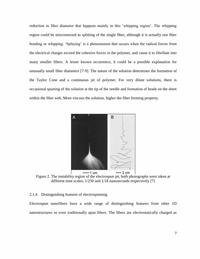
reduction in fiber diameter that happens mainly in this ‘whipping region’. The whipping
region could be misconstrued as splitting of the single fiber, although it is actually one fiber
bending or whipping. ‘Splaying’ is a phenomenon that occurs when the radical forces from
the electrical charges exceed the cohesive forces in the polymer, and cause it to fibrillate into
many smaller fibers. A lesser known occurrence, it could be a possible explanation for
unusually small fiber diameters [7-9]. The nature of the solution determines the formation of
the Taylor Cone and a continuous jet of polymer. For very dilute solutions, there is
occasional spurting of the solution at the tip of the needle and formation of beads on the sheet
within the fiber web. More viscous the solution, higher the fiber forming property.
Figure 2. The instability region of the electrospun jet, both photographs were taken at
different time scales, 1/250 and 1/18 nanoseconds respectively [7]
2.1.4 Distinguishing features of electrospinning
Electrospun nanofibers have a wide range of distinguishing features from other 1D
nanostructures or even traditionally spun fibers. The fibers are electrostatically charged as

8
they are ejected from the nozzle and hence their direction can be easily controlled with an
external field. Alignment of the fibers can be made parallel. Due to these distinctive
characteristics, the same application can be made more efficient using this process.
(1) Exceptionally long length: Relative to 1D nanofibers made by all other methods
electrospun ones are very long; continuous fibers up to several kilometers in length
can be spun. It has been theoretically and experimentally proven that these fibers are
continuous [10]. The fluid instability causes randomly-oriented collection of fibers
resulting in a porous sheet of fibers. Having said that, spatial orientation of the fiber
and position can be easily controlled by moving the collector or experimenting with
different collector types [7].
(2) Exceptionally high surface-to-weight or volume ratio: As dimensions decrease, the
specific surface area increases, more so for nano-scale materials. The fiber diameter is
in the scale of 1x10⁻⁹ meters and very long, hence have very large surface areas at low
volumes. The surface activity of such structures is more pronounced: unusually high
surface energy, surface reactivity, strength-to-weight ratios and thermal and electrical
conductivity. The entanglement of these ultra-thin fibers impart high porosity i.e.
larger number of pores per unit volume [10].
(3) Alignment at a molecular level: Certain end-uses specifically require a particular
alignment of the fibers; cell elongation and proliferation have been demonstrated to
align themselves in the direction of the nanofibers, for enhanced tissue engineering
[10]. Electrospinning involves stretching of the jet and rapid evaporation of solvent
and hence fibers are subjected to high shear forces. This shear force prevents the

9
fibers for going back to their equilibrium conformations. So, the crystallinity and
chain conformations of the resulting nanofibers are different from what other
spinning methods would have produced [7]. At a macroscopic level, fiber alignment
can be manipulated by the type of collector and drum rotation speed or selectively
charged targets; many such innovative approaches continue to be made [1-3].
2.1.5 Applications in Biomedical Engineering
The simplicity of the fabrication scheme, the diversity of the materials useful for
electrospinning and the unique features of such nano-structures, all make this technique
attractive for a number of applications. Our focus in this work has been on the biomedical
applications of electrospinning.
There are several important reasons for electrospinning to be the favorite for medical textile
manufacturing. Man-made scaffolds are fabricated with nonwoven 3-dimensional mats that
mimic the natural scaffolds in terms of morphology, chemical composition and surface
functional groups. They provide an ideal class of materials to bear similarity to the extra-
cellular matrix for supporting the growth or regeneration of cells. Wound dressing is a being
highly explored as an application for electrospun fabrics as they are breathable as well as
they protect the wound from bacterial penetration via aerosols. All these requirements can be
easily fulfilled by a cost-effective, versatile, consistent and simple process such as
electrospinning. It provides a simple method to incorporate carriers of ‘active ingredients’ by
embedding in these dressings, specific enzymes, chemicals or drugs [2-10]. The effects of
nano-fibers when combined with intrinsic properties of biopolymers, enhances their appeal.

10
Our effort here, is to electrospin nonwovens from polymers with potential antimicrobial
activity; such properties are more prevalent among polymers from natural sources than
synthetically produced ones.
There are some other applications listed below that are also popular and are constantly
evolving:
(1) Nano-fiber reinforced composites: Reinforcing nanofibers in the matrix of other
polymers or materials increases mechanical properties to great extent due to their high
surface-to-volume ratio. Better interaction at the molecular level leads to better
reinforcement as compared to conventional fibers. Due to the cross-sections of
electrospun fibers being small, the composites can maintain optical transparency.
(2) Nano-fibrous mats and smart cloths: It has been investigated that electrospun fibrous
mats have higher resistance to convective air flow compared to other materials and
lower resistance to water vapor flow through the pores. The filtration is high although
a very thin layer is made.
(3) Nano-fiber based sensors: Blending fluorescence particles into the fibers as active
components made smart sensory nanofibers. The sensitivity of these materials to
metal ions was 2-3 magnitudes greater than other continuous films. This was mainly
due to the larger surface area and easy transport of analytes to active sites of the nano-
fiber.
(4) Nano-fibers as coating materials: Also referred to as sacrificial templates, 1D
structures have been prepared by coating a range of polymers, ceramics, and metals

11
with electrospun fibers on the hollow interiors of tubes thus making ‘nanotubes’. The
template is then sacrificed which was used as a frame.
(5) Enzymes and Catalysts: The porous, compact nature and large specific surface area of
nanofibers (polymeric and ceramic) provide excellent support for enzymes and
catalysts. ‘Bio-active’ nanofibers can be prepared by chemically adhering the enzyme
to the surface of the electrospun fiber of a typical diameter of 120nm. Enzyme
activity has been found to be six times more than what it is in a normal polymeric
structure.
(6) Electronic and Optical devices: These find potential usage in the telecommunication
industry, for example, arrays of uniaxially aligned nanofibers have been demonstrated
for use as inexpensive optical polarizers.
2.1.6 Controlling parameters influencing the nanofiber properties
The desired fiber morphology via electrospinning can be achieved by manipulating the
different factors that govern the process of electrospinning. Primarily, the fiber diameter, the
fiber alignment on the collector and proportion of bead formation are usually the factors
regulated in this process. The applied voltage, solution flow/feed rate, solution viscosity, the
distance between the syringe tip and collector are directly responsible process parameters to
control fiber diameter. But, in addition to these parameters, the properties of the solution and
ambient conditions of humidity and temperature also play a role in the fiber morphology and
diameter [1], [6], [7], [10]

12
Electrospun fibers are generally circular in cross-section. Major factors that affect the
diameter of the fibers are the concentration of the solution, electrical conductivity of the
polymer, electrical field strength and the solution flow rate. Fiber diameter or thickness
increases with the solution concentration in other words as viscosity increases. This is also
the case with higher flow (feeding) rate of the fibers [7]. Several models have been proposed
to explain the interplay of the various parameters over fiber morphology. Increasing supply
voltage has the same effect as increasing flow rate and decreasing the tip-to-collector
distance, but there are deviations from this observation as well. Some other authors have
reported that increasing voltage, causes greater stretching of the solution due to the greater
columbic forces in the jet as well as a stronger electric field and these effects lead to
reduction in the fiber diameter and also rapid evaporation of solvent from the fibers results.
With regards to the flow rate and the tip-to-collector distance, their effect on fiber
morphology depends upon how much time is allowed for the solvent to evaporate till the
fiber reaches the collector. There must always be a minimum flow rate for the spinning
solution and a minimum distance to ensure the fibers are dried completely of the solvent
before they settle on the metal foil [1].
The presence of beads is a common problem in electrospinning. The viscosity of the polymer
solution, surface tension and density of net charges carried by liquid jet all influence the way
fibers are made. However, the surface tension force that minimizes the surface area, the
electrostatic repulsion between like charges in the polymer droplet, and the visco-elastic
force that resists rapid changes in shape, these 3 forces cause formation of beads mainly. But
most efforts by researchers have proved that more viscous the solution, lesser the occurrence

13
of beads. Addition of salts to increase the net charge density and inclusion of solvents with
less surface tension could also eliminate beads. [6], [7]
The various parameters that control electrospinning are summarized as below:
Table 1. Parameters Controlling Electrospinning
Operational conditions Intrinsic properties of the
solution
Ambient conditions
1. Applied voltage
2. Solution flow rate
3. Tip to collector
distance
4. Shape of the
collector
5. Geometry of the
spinneret
1. Solution viscosity
2. Molecular weight of
the polymer
3. Conductivity of the
polymer, solvent
and solution
4. Solution
temperature
5. Added salts to the
solution
6. Vapor pressure of
the solution
1. Environment
temperature
2. Environment
humidity
2.1.7 Structure-property correlation
The ability to achieve very minute pore sizes due to the formation of very minute fibers,
distinguishes electrospinning from other fiber spinning techniques in the same application.
Tissue-engineered scaffolds and nonwoven sheets with potential antibacterial properties or
nano-filters have in recent efforts shown increased efficiency due to very high surface area at
the nano-level. In such end-uses it is required to have uniform, controlled pore sizes,

14
enhanced specific surface areas and accurately defined permeation properties, because the
properties of these materials are sensitive to the changes in these parameters.
Electrospun fiber mats have been extremely successful in Tissue Engineering or medical
textile applications. They are structurally and morphologically similar to the extracellular
matrix of the natural tissue which is characterized by a variation of pore sizes and mechanical
properties [8]. These pores could alternatively serve as drug (or antibacterial ingredient)-
carrying spaces. Hence, it is imperative to know the relationship between the structure of the
nonwoven and how it affects the functionality. A study by Hussain et al suggests that it is
possible to engineer electrospun nanofiber based nonwovens with pre-determined properties
and applications in quite a controlled way. The study was done on polyacrylonitrile (PAN)
and PA 6 (Nylon 6) nanofibers [11].
Electrospun nonwovens are characterized by polygonal shaped pores unlike circular in other
structures, and hence differ strongly in their characteristics. As fiber diameter increases, the
pore size increases, where these pores are defined by the fibers acting as boundaries; this can
be observed by visual analysis. The plot below shows the effect of polymer concentration in
the spinning solution on fiber diameter. The error bars indicate that these pore sizes are also
subjected to some distribution. The pore size is a crucial parameter in nonwoven filters.

15
(a)
(b)
Figure 3. Variation of (a) fiber diameter with polymer concentration in spinning solution (b)
geometric pore size with fiber diameter [11]
For a wound dressing made from a nonwoven mat, the vital attributes that it must possess are
absorption ability of excess exudates (wound fluid/pus), appropriate water vapor transmission

16
rate, adequate gaseous exchange ability. The flow of such fluids from one end of the nonwoven
to the other again has a direct relationship with the pore configuration. It is easy to meet these
requirements with the manipulation electrospinning parameters [1]. The permeation properties, in
other words, fluid flow through nonwovens, can be analyzed as a function of the pressure drop,
using a capillary flow porometer. The plot below reveals that gas flow increases roughly linearly
with increasing pressure drop and that it increases at constant pressure drop with increasing fiber
diameter [11].
Figure 4. Gas flow as function of pressure drop across the nonwovens (along z-axis,
perpendicular to fiber planes) using the fiber diameter of PAN fibers as parameter [11].
2.1.8 Suspension Electrospinning
Electrospinning can be done from various forms of the polymer- Melt Electrospinning
(polymer melt is introduced into the capillary tube, instead of a solution), Emulsion
Electrospinning (made from a mixture of two or more immiscible liquids with one in the

17
dispersed phase and the other continuous phase), Solvent-based electrospinning (completely
miscible homogeneous solution of a polymer/s in the solvent) and Suspension
electrospinning. Our research aims at finding a suitable method to form electrospun
structures using Soy Protein Isolate, which in turn makes uniform aqueous dispersions in
water.
Suspensions are mixtures of usually water as the liquid and finely dispersed solid particles.
For example, the suspension of polymer particles in water is made from conventional or
mini-emulsion polymerization, also known as a polymer dispersion or latex. In general, these
are called primary lattices that are obtained directly by emulsion polymerization. Secondary
lattices are those that are made from any water-insoluble polymer in water. However, the
concentration range and conditions required for successful preparation of secondary
suspensions is crucial [12].
2.1.9 Problems encountered during electrospinning
There are several parameters that govern the process; these individually pertain to the
polymer solution itself, the external set-up of the process, and lastly ambient conditions. This
makes it a longer process to optimize or standardize, especially so when working with a
relatively newer material. It is hence, important to understand, as one is studying the fiber
formation:
(1) The interplay between each of these parameters
a) Is the voltage range appropriate?
b) Does the collector need to be rotated at high speed?

18
c) Are the electrical connections correct?
(2) The behavior and nature of the polymer (e.g. how does it behave over time)
a) Does the solution remain stable over long periods of time?
b) Biopolymers, such proteins tend to denature, which in turn depends upon factors
such as Temperature, pH and lastly over time. Denaturing is generally important for
spinning applications. This is explained further in the section that deals with Soy
Protein Chemistry.
(3) Possible interaction between polymers, in case of a blend
2.1.10 Limitations of Electrospinning
The major limitations of electrospinning are its low production rates and the necessity of
having to use and recover solvent, which obstruct it from being a commercially viable
process. Such issues could be eliminated by melt electrospinning. Some important issues are
listed below:
(1) Production rate is very low; approximately 0.1 gms/hour/meter. In general,
electrospinning has low productivity as the polymer solution has to be fed at
relatively low rates (1 mL/hr). This could be overcome by having multiple needles.
(2) We may not yet know overall interactions of parameters. Most research papers
investigate the effect of only one or two parameter.
(3) Produced nanofibers are not uniform in terms of their diameter since a wide range of
values in the nanometer range.

19
(4) Formation of beads in the nonwoven web.
(5) Hazardous organic solvents may be used; hence the process is not ‘green’.
2.1.11 Electrospun Soybean protein fibers: As wound dressing material
The advantages of electrospun nonwoven mats and those made from natural polymeric
materials opens up many more opportunities for us to explore. Among many such bio-
polymers, soy protein is a relatively new entrant to the field of electrospun biopolymers.
Proteins have the advantage of being economically competitive and present good water
resistance as well as storage stability. Biopolymers are renewable resources but also
intrinsically exhibit biocompatibility, biodegradability and anti-bacterial activity. The
following chapter discusses how the potential antimicrobial activity of soy protein has been
proposed and the possibility of replacing the more expensive and seasonal chitosan.
Electrospinning is still evolving as a method to spin textile fibers. Nearly, every synthetic
polymer has been shown to be electrospinnable and today several bio-polymers are also
being investigated. Hence, there is no limitation as regards the selection of raw materials.
2.2 Soy Protein Isolate
This chapter critically reviews all previous work in the field of electrospinning of
biopolymers to create antimicrobial materials; specifically, wound dressings having this
property. Biopolymeric materials inherently are biocompatible, have low immunogenicity
and resist or kill bacterial growth. Electrospinning of such biopolymers into nanofibers

20
provides one with advantages of properties such as relatively very high porosity, pore
interconnectivity, drug-carrying capacity and close similarity to the extra-cellular matrix in
the body. Our active ingredient, Soy Protein (isolated form) is being analyzed for
antimicrobial activity. It is helpful to understand the behavior of soy protein aqueous
dispersions and how denaturation affects the stability of these dispersions.
2.2.1 Importance of biomaterials in healing applications/medical textiles
Medical textile products are made from a wide range of materials of synthetic and natural
origin. A few trust synthetic fibers for their consistence and strong mechanical properties.
While, some prefer going the ‘green’ way by choosing bio-materials such as chitin, chitosan,
collagen, and gelatin for their biodegradability and ability to mimic natural conditions.
Several attempts have been and are being made to optimize the process parameters in
fabrication of such materials along with exploring the behavior of different combinations of
materials.
Biopolymers are renewable resources and may also intrinsically exhibit biocompatibility,
biodegradability and anti-bacterial activity [10], [13]. Nanofibers made out of biopolymers
find applications in reinforcements in nano-composites, sutures, filters for metal recovery
and protective clothing [10]. Recent developments in the electrospinning technology have
produced scaffolds made of nanofibers. Electrospinning process parameters can be varied to
achieve difference in pore size, number of anchoring sites, degree of wetting and degradation

21
rates. Porosity of the material is one of the factors that determines the efficiency of medical
textiles, battery separators, filters and fiber composites [10].
Biopolymer nanofibrous mats have shown potential for applications within the medical field
due to the aforementioned intrinsic properties of these renewable materials [10], [13].
Medical and pharmaceutical fields could use nanofibers to fabricate wound dressings, tissue
engineering scaffolds for drug delivery, or other medical devices. The success rate of
artificially recreating the extracellular matrix and other tissue engineering applications
depends on the properties of the scaffolds, such as their biocompatibility, osteoconductivity,
degradability, high surface-area-to-volume ratios, and mechanical properties [13].
While these various natural polymers are being explored for fabrication of biomaterials, plant
proteins are preferred over carbohydrates because of their easy availability, low potential to
be immunogenic and ability to be made into fibers, films, hydrogels and micro- and nano-
particles for medical applications. Proteins are preferred over synthetic polymers (more
importantly carbohydrate polymers) because they form a major part of the human body, they
are ‘bio’- and ‘cyto-’ compatible, and it is easier to maintain their functions in the extra-
cellular matrix than with synthetic polymers. Plant proteins are co-products generated when
cereal grains such as corn and wheat are processed for food or fuel. They have considerably
less potential to be immunogenic as compared to traditional biopolymers such as bovine
collagen. Proteins are most suited for especially drug-delivery mechanisms; their wide range
of isoelectric points helps one choose specific proteins for the specific drug. Owing to the
several advantages of plant proteins compared with collagen and silk, efforts have been made

22
to explore the possibilities of utilizing plant proteins to develop hydrogels, films, fibers,
nano- and micro-particles for medical applications, mainly tissue engineering and drug
delivery [14].
On the flip-side, these plant proteins have inferior mechanical properties, especially poor
hydrolytic stability compared with silk but better than collagen-based biomaterials. Some
other plant proteins that have remained fairly unexplored are zein from corn, soy proteins and
wheat gluten. Thermoplastics made of soy proteins were found to have mechanical and
degradation properties suitable for scaffolding. Soy protein promoted higher growth of cells
than another natural polymer such as chitosan when it was used as part of the cross-linked
blend [13], [14].
This paper critically reviews the various attempts at electrospinning biopolymers, alone or in
combination with other synthetic polymers and the results that were achieved thereafter. The
concept of electrospinning a blend of Soy and Chitosan to make nanofibers is proposed,
based on previous research where these were spun individually or with other polymers. It is
anticipated that both materials would complement each other in mechanical and functional
properties.
2.2.2 Electrospinning: A method to produce bio-polymeric nanofibers
Electrospinning scores over other methods to generate nanofibers because of the simplicity of
the process and uniformity of the fibers produced. Nanofibers have dimensions of the order
of 1 x 10⁻⁹ and surface properties are different on that level from other lower magnitudes.
Nanofibers are today widely used in tissue engineering applications as scaffolds and have the
following properties that differentiate them from conventional fibers for bio-medical end-

23
uses [7], [3], [15]: (1) Increased surface area as fiber diameter decreases, and hence
unusually high surface energy, (2) Raised surface reactivity, (3) Fibrous mats can mimic the
extra-cellular matrix (ECM), (4) Enhanced drug loading capacity, and (5) Increased strength
even at low density
In the past decade, research has seen resurgence in electrospinning of nanofibers from natural
polymers owing to vast possibilities for their enhanced use in bio-based materials. Many
parameters like solution properties, processing and ambient conditions influence the
transformation of polymer solution into nanofibers during the electrospinning process. With
their distinctive properties, nanofibers have found applications in wound dressing, filtration,
composites, tissue engineering and others. For most applications, it is always desirable to
have smooth, ultrafine nanofibers with uniform diameter [15].
Through electrospinning, biocompatible polymers can be spun into a nano-sized mesh. This
nanomesh would be composed of fibers with a high surface area, and a nano-sized diameter
that can be used to mimic a natural extra-cellular matrix, which acts as scaffolding material
that allows cells to attach, proliferate, differentiate, and develop essential functions within
tissue [16].
Electrospun nonwoven type of biopolymers have a plethora of applications in medicine,
aerospace, filtration and protective textiles and are being considered for additional research.
Li and Younan reviewed the process of electrospinning and reported that what electrospun
nanofibers form is a nonwoven web. For tissue engineering applications, several synthetic as
well as bio-polymers have been used as 3D scaffolds for tissue growth or as nonwoven

24
membranes. For example, wound-dressings have been made from porous mats consisting of
fibrous structures that can protect the wound from bacterial penetration via an aerosol
particle capturing mechanism while having breathability. Thus these structures serve as drug
carriers [7].
2.2.3 Wound Dressings from Electrospun Fibers
The Function of Wound Dressings and the Process of Healing
Wound healing is a process of regeneration of tissue after dermal or epidermal damage.
Healing of deep cuts or burns takes a long time for complete re-epithelialization and scar
tissue formation to take place. All wound repair materials must possess certain fundamental
qualities such as: [17] (1) Prevent and control infection in the wound and surrounding areas,
(2) Make the environment moist, (3) Improve comfort and protect the wound from further
trauma, (4) Absorb the exudates, if any, (5) Accelerate the process of wound-healing in
general
Polymeric nanofibers have excellent pore densities and pore inter-connectivity for exuding
fluid from the wound. Electrospinning, additionally provides a means to embed drugs into
the nanofibers for any possible medical treatment and/or antimicrobial purposes. Electrospun
polyurethane mats have shown to effectively exude fluid from the wound, without fluid
stagnating under the wound cover and also no wound desiccation either. Dermal wound
repair has been done effectively using electrospun nanofiber mats (scaffolds) that closely
resemble the ECM. Besides, in place of impregnating polymeric nanofibers with antibacterial
additives, polymers like chitin that are inherently antimicrobial have been explored [17], [4].

25
The mechanical strength of wound dressings is overrated. Biocompatibility and efficient
antimicrobial activity are relatively more crucial requirements in a wound dressing than
mechanical strength. It would be futile to compare the strength of fibers made by
conventional spinning techniques such as melt or wet spinning with that made by
electrospinning. Electrospun nanofibers are not distinguished for their mechanical properties,
but for their morphology. It is therefore, reasonable to not overvalue the strength of the
nanofibers. Our aim here, is to achieve a suitable recipe that assures us of a product that
forms continuous fibers, resists microbial invasion and/or encapsulates drugs.
Encapsulation is an important property of electrospun nonwoven webs. Enzymes stored
inside the pores of the web have shown better activity in the body of the organism. Fibers
normally used in the past include polyurethane or collagen. Such structures can also be
referred to as ‘Antibiotic Impregnated Nanofiber Membranes’ since they embed medicinal or
healing materials in them [7]. Additionally, by electrospinning fibrous mats, a three-
dimension malleable scaffold is fabricated. Thus, it could be molded around, spun directly
onto, or into the pores of whatever size substrate that needs cell seeding.
Past attempts on producing wound dressing materials from Electrospun structures
Various biopolymers have been electrospun in the past. Cellulose, cellulose acetate, chitin,
chitosan and chitosan with polyethylene oxide (PEO)/polyvinyl acetate (PVA)/polyethylene
terephthalate (PET), proteins like collagen, gelatin and recently soybean are some of the
natural polymers used in electrospinning. A few important ones are discussed here.

26
Cellulose: Being the most renewable, abundant and versatile polymer, cellulose has been one
of the longest studied materials for electrospinning. Problems were faced when cellulose
would not dissolve in conventional solvents dimethylsulfoxide/paraformaldehyde or sulfur
dioxide due to its strong inter- and intra-molecular bonds. However, these solvents were not
suitable for electrospinning. Due to the problems associated with dissolving cellulose, it is
common to use cellulose derivatives (cellulose acetate and propionyl cellulose), which do
dissolve in common solvents. In some cases, the disadvantage of cellulose derivatives, is the
reduced stability and degradation of the cellulose structure. Oxidized cellulose was also
explored as it degrades under physiological conditions and is bioresorbable; it has been used
as a resorbable homeostatic dressing, in cosmetic preparations, fibrin formation catalysis-
agents, and adhesion barriers. Cellulose composites made with biocompatible, non-toxic, and
chemically resistant polymers like polyvinyl alcohol (PVA) and polyethylene oxide (PEO)
provides better fiber-forming properties. Moreover, changing the ratio of cellulose
acetate/PVA altered the mechanical properties as well. Guanfushou and Liu reinforced soy
protein isolate films with cellulose nanofibers. Cellulose nanofibers were made by
hydrolyzing electrospun nanofibrous mats made from cellulose acetate solution [10], [15],
[18].
Chitin: Second to cellulose, chitin is the most abundant organic material produced by
biosynthesis. However, use of chitin in many applications has been limited due to its
insolubility in most organic solvents. The process parameters for the electrospinning of chitin
and chitin-containing solutions, including: MW, degree of deceleration (DD), solvent used,
special polymer processing, electrospinning parameters. Chitin electrospun mats were also
27
blended with other polymers such as poly (glycolic acid) PGA; the blended fibers degraded
faster than pure PGA fibers since PGA is both biodegradable and biocompatible [10], [15],
[19].
Chitosan: It is the N-deacetylated derivative of chitin and derived from the shells of crabs
and other crustaceans which contain about 85% chitosan. The solvent choice is one of the
most important optimizing parameters in electrospinning. For chitosan there is a wider range
of solvents to choose from than for chitin as it is soluble in many. It has successfully been
electrospun with trifluoro acetic acid (TFA) and acetic acid (AA). However, chitosan needs
to be made chemically stable before being applied in end-uses. It is cross-linked in a two-step
process with gluteraldehyde in a vaporization chamber. Chitosan blended with other
polymers like PVA showed that higher concentration of chitosan improved the morphology
of the electrospun fibers. Chitosan/PVA nonwovens were observed to have high water-
uptake abilities and hence suitable for use in wound-dressings. Due to the polyelectrolytic
nature of chitosan, it has a high viscosity in dilute aqueous solutions. Therefore, it can be
desirable to use chitosan as a thickener, especially since it is compatible with other
biocompatible polymers such as PVA and PEO. Sometimes beads are observed when
electrospinning. To counter this, additives such as salts or surfactants can be used. Similarly,
cationic and anionic polyelectrolytes could increase the conductivity of a solution and thus
decrease fiber diameter. Similar successful attempts were made with chitosan and PET or
chitosan and PEO [10], [15], [18].

28
Collagen and gelatin: Proteins are the key component in scaffolding, protection, growth etc.
Bio-proteins such as collagen and gelatin derived from animal tissues have been extensively
researched despite their complicated structure and chemistry [10], [7], [15].
Collagen: is available in different grades based on the source; from calfskin, human placenta
or bovine ligament. Collagen generally is cross-linked with other chemicals or is
incorporated in a composite nonwoven mat (containing PEO, (polycaprolactone) PCL,
chitosan, etc.) for better chemical and mechanical properties.
Gelatin: Similar to collagen in composition and biological properties from which it is
derived, it is highly polar and electrolytic in character.
Silk: Silk is also a very common fiber after collagen used in tissue engineering applications.
It has excellent mechanical properties although, only fibroin in silk is biocompatible, sericin,
the gummy substance, is toxic to the cells. Moreover, among other plant proteins collagen
and silk are more readily available and can be easily fabricated into scaffolds such as fibers
or films having good mechanical properties [10].
With nanofibers made from protein that are actually amphiphilic biopolymers, they are ideal
because they interact equally with both the drug and solvent. So far, drug-loaded
nanoparticles have been synthesized from insoluble proteins (zein, gliadin) as well as
soluble proteins (bovine collagen) [20].

29
2.2.4 Soy Protein Fibers: Composition and Properties
Availability, Chemical Composition and the Different Processed Forms
Soybean is an important source of protein and its production in North America continues to
increase as the yield and per-acre income continue to increase steadily. It is a seasonal crop
and is planted usually in the months May-June and harvested during October-November.
Majority of the soy produced is used for oil production, textiles, or fiber formation than for
direct consumption. Soybean contains approximately 40% protein (highest among legumes)
on a dry weight basis. Soy-proteins are available in 3 forms namely [24]: (1) Soy-protein
isolate (SPI) - contains 93 % soy protein fiber, (2) Defatted Soy flour (SF) - contains 74%
soy protein fiber, (3) Soy-protein concentrate (SPC) – contains 53% soy protein fiber.
SPI being the purest form of the protein, is used for fiber extrusion. It is made from defatted
soy flakes during the production of oil and contains a minimum of 90% protein. Soy-protein
is abundant, biodegradable, biocompatible and inexpensive, all of which make it a suitable
polymer for addition in fiber spinning solutions [23]. Our target applications are in medical
textiles, which require polymers that resist bacterial contamination and that do not generate a
toxic response in the body tissues, while being cheap.
Soy protein, the major component of the soybean, has the advantages of being economically
competitive and presents good storage stability. The combination of these properties with a
similarity to tissue constituents and a reduced susceptibility to thermal degradation makes
soy an ideal biomaterial [22]. Soy protein has functional groups such as –NH2, -OH, -SH that
are susceptible to chemical and physical modifications. Some studies have reported that the

30
combination of soy with other proteins like casein, and polysaccharides such as cellulose and
chitosan in film form may trigger surface interactions which could improve certain properties
[23].
Soy protein fibers could be found in various forms namely, as Textiles (Soy fibers could be
woven or knitted into apparel such as socks with antimicrobial properties), as Composites
(they could be the reinforcing fibers in a synthetic or biopolymer matrix), as Nonwoven webs
(electro-spun soybean is gaining popularity as it has the surface potential to immobilize
enzymes [7], [21].
Figure 5. A schematic showing that as viscosity increases formation of beads reduces [3]

31
Soy Protein Isolates (SPI)
Grades of SPI, Chemical Composition and Physical Properties
Isolates are the most refined form of soy protein products that are also commercially
available. They represent the major proteinaceous fraction of the soybean. Prepared from
dehulled and defatted soybeans by removing most of the non-protein components, isolates
contain more than 90% protein on a moisture-free basis. They are available in different
varieties such as gelling and non-gelling, various viscosity grades and various dispersibility
indexes.
We have used neutralized isolates throughout our analysis; the isolate is neutralized (Na or K
proteinates) to make it more soluble and functional. About one-third of the starting flake
weight is recovered in the form of an isolate. The applications for this form is varied- meat
and dairy products, or basically applications requiring emulsification, emulsion stabilization,
water and fat absorption, adhesive-or fiber-forming properties, and food analogs [25].
Pro-Fam® 974 and Pro-Fam® 955 are the commercially available grades of Soy Protein
Isolates that are used in our composition. Archer Daniels Midland (ADM) Company, one of
the world’s largest producers of specialty food ingredients, has several grades of isolates, for
example, Pro-Fam®. Pro-Fam® 974 and Pro-Fam® 955 are identical in composition and
denaturation behavior in solution, only differing in the method they were processed in [26].
Both grades are soluble and dispersible, specifically used in systems requiring functional
proteins. Figure 6 summarizes the chemical make-up of Pro-Fam® 974.

32
Figure 6. Chemical Composition of Pro-Fam® 974 [28]

33
Proteins can be defined as natural polymers able to form amorphous three-dimensional
structures stabilized mainly by non-covalent interactions. The functional properties of these
materials are highly dependent on the structural heterogeneity, thermal stability, and
hydrophilic behavior of proteins. A number of proteins of plant origin have received attention
for the production of biodegradable polymers. These proteins are corn zein, wheat gluten, soy
protein, and peanut protein [27].
Isolates are imparted functionality by virtue of the properties like solubility and gelation. The
following chart enlists these properties and also their mode of action [29].
Table 2. Functional properties of Soy Protein Isolates [29]
Functional Property (Isolates) Mode of Action
Solubility Protein Solvation, pH dependent
Viscosity Thickening, Water Binding
Gelation Protein Matrix Formation and Setting
One of the issues with soy protein is the hydrophilic nature of the protein molecule, due to
which the soy-based materials are sensitive to moisture and hence difficult to store over long
periods of time. This hygroscopicity is because of the large percentage of protein in soy
protein isolates, about 90%. Soy protein is composed of two kinds of globular proteins- 11s
and 7s. The 11s type is a relatively hydrophobic molecule, but the 7s protein constitutes upto

34
70% of the total protein content of the SPI. Hence, the overall nature of SPI is hydrophilic
[30]. Soy-based materials, sometimes referred to as “green” plastics suffer from low strength
and high moisture sensitivity. These factors curb the commercial viability of such materials.
Usually plasticizers or additives are required to impart strength to the blend [31].
Isolates have specific functional characteristics that enable them to modify the physical
properties of food products. Some of these are desirable for non-food applications as well:
Solubility, gelation, emulsification, dispersibility, viscosity and retort stability. Neutralized
isolates are usually highly soluble; certain types will gel under appropriate aqueous
conditions. They vary mainly in their in their dispersibility, gelling, and viscosity
characteristics [29]. These characteristics soy proteins depend mainly on their method of
preparation, processing conditions, presence of salts, pH and temperature [32].
Denaturation and its effect on the fiber formation property
Denaturation is a process that is undergone by proteins specifically, when exposed to strong
acids/alkalis, heat, organic solvents, detergents or urea. The native globular proteins are
modified from their secondary, tertiary or quaternary structures i.e. converting into unfolded
polypeptide chains, which are connected with interchanging of disulfide (-S-S-) bonds [37].
Globular proteins are composed of segments of polypeptides connected with hydrogen
bonds, electrostatic interactions, disulphide bonds and hydrophobic interactions.
Conformational changes of unfolding globular proteins through denaturation process [33]
and reducing the inclination of denatured proteins to form aggregates are important for

35
spinnability of a spinning dope with proper relative viscosity. It is also important for later
drawing of fibers and crystallization of proteins in fibers.
Denaturation is also the process that causes the protein to lose its active sites, in other words,
its functionality. Strong heat treatment causes the rupture of inter and intra-molecular bonds
of the native protein structure, leading to loss of solubility, a characteristic property of the
protein. Delia et al demonstrated that, when native SPI is made into a solution, a high yield of
soluble fraction obtained; visibly noticeable and approximately 98% in distilled water at pH
7. On heating the solution at 800C or higher, for 30 minutes, and then leaving it overnight to
cool, two fractions- soluble and insoluble, are formed. It is also observed that, for solutions
that are 5% (w/w), a viscous aqueos dispersion is formed; while for solutions greater than 8%
(w/w), gel-like formation starts. Thermal treatment may bring down the solubility of a highly
soluble SPI: the heating led to varying fractions of soluble and insoluble SPI depending upon
the extent of denaturation [34].
The further sections illustrate the experiments carried out to characterize the Soy Protein in
terms of visual assessment and relative viscosity measurements. How the viscosity changes
over time for an undisturbed solution, would help better understand the effect of combined
thermal and alkali denaturation.
Gelation
From a food processing standpoint, soy protein isolates aid in forming gels which acts as a
matrix for holding moisture, fat and solids. Textural properties, such as those in tofu make
use of this gelation. The ability of isolates to form gels (ranging from fragile to firm) depends

36
upon the concentration, functionality and the presence or absence of salts; some isolates are
designed not to form gels even at a concentration of 14% (w/w) [29].
It is observed that beyond a concentration 8.5 % (w/v), Pro-Fam® 974 tends to form a gel
[24]. Varzakas et al explained the sol-gel mechanism of SPI by studying the effect of pH,
temperature and concentration on the gel strength. Heating increases the protein-protein
interactions at relatively high concentration and this resulted in an increase of solidity. These
interactions between protein molecules lead to aggregation, coagulation or gelation in the
protein dispersion. Isolates are seen to be soluble over a wide range of pH values, even at less
than 4.6, the loss of solubility (formation of gel), can be attributed to the extent of
denaturation. However, heating to higher temperatures, results in lower gel strength. Hence it
was concluded that, the tendency to form stronger gels is at lower temperature and higher
concentration [35].
2.2.5 Blends of Soy Protein with different Polymers
To date, electrospun 100% soy fibers have not been reported in the literature. Unlike fibrous
proteins such as collagen and gelatin which have been extensively and easily electrospun in
the past, the globular structure of soy-proteins must be unfolded by denaturation treatment to
enable electrospinning. Soy alone is not a strong enough fiber owing to poor mechanical
properties and other disadvantages that come with using natural polymers. Studies done in
the past have proved that initially due to high surface tension of water and low solution
viscosity there was formation of dough and beads in the fibers electrospun from an aqueous
polymers solution of 100% soy. It was then blended with PVA (or some other biodegradable

37
polymer) to hold or bind the soy together [13], [23], [24]. Figure 7 shows how an increase in
the polymer concentration, or solution viscosity, the resultant morphology changes goes from
beads to uniform fibers.
Figure 7. An example of how morphology of electrospun fibers changes from beads/film to
continuous fibers as polymer concentration increases in the solution from 1% through 5%
[33]
Another recent study built on a previous study suggesting that agro-wastes from oil palm and
soybean (okara) could be spun into nanofibers using electrospinning technology, by
developing and evaluating an agrowaste-based nanofiber encapsulating lactic acid bacteria
[36].

38
Soy-proteins contain fewer proteins and hence the range of solvents to electrospin them is
limited. In the past they have been developed for ‘hydrogels’ for controlled release of the
drug embedded in these gel structures. The other forms of soy-proteins are fibers and films.
Fibers are stronger than films. They are mainly involved in tissue engineering applications as
they mimic the extra-cellular matrix. Moreover, these tissue engineering applications use
nanofibers form of soy (with other polymers). Protein fiber from soy have certain specific
advantages like water stability, biocompatibility, strength required for medical textile
applications, without having to cross-link them [13], [23], [24].
Significant research has been performed on the co-blending of soy protein with other
biopolymers [30]. Moreover, most soy-containing products are multi-component systems. In
cases, where the protein cannot impart the desired functionality, it can be done by
incorporating additives in the spinning solution [32]. The industry at present, focuses on
these additives being biodegradable, such as polyvinyl alcohol, poly lactic acid, starch
(cellulose) to name a few [27].
100% soy-protein fibers by wet-spinning
Reddy and Yang investigated the possibility of producing 100% soy fibers with water
stability and mechanical properties suitable for tissue engineering applications without using
cross-linking agents. The fibers were prepared using wet-spinning with solvents such as urea
and sodium sulfite. The spun fibers were tested for their mechanical properties on the Instron
Tensile tester, physical structure, water stability and scaffolding ability. The diffraction
pattern showed that soy fibers had low crystallinity and poor orientation. The tensile strength

39
of soy was seen to be higher than other cereal proteins which could have been largely due to
the optimum aging time and temperature in the solution. The water stability of soy fibers was
better than polylactic Acid (PLA) fibers in the 3-11 pH range, 900C for one hour. As regards
the morphology, the fibers were 50-150 μm with a uniform longitudinal surface with
striations that help in cell attachment. Overall, it was concluded that soy proteins are novel
biomaterials for the medical textile applications [13].
Soy protein isolate and Polyethylene oxide fibers
Soy protein when synergized with PEO fibers was found to enhance the electrospinning of
the protein solution by increasing solution viscosity and reducing electrical conductivity.
Vega-Lugo et al mixed 100% SPI with different concentrations of PEO to achieve various
morphologies of fiber (fibers, beads, combination of both). 100% SPI when denatured in
combined thermal and alkaline treatment could not be spun into a fiber readily. However,
when PEO solution was added SPI could be readily spun resulting in fibers of diameters 200-
260nm. Non-ionic surfactant added to improve the surface tension of the spinning solution,
helped facilitate the dispersion of the SPI powder for making homogeneous polymer
solutions [23].
Soy protein isolate and polyvinyl alcohol (PVA) fibers
PVA is a common choice among synthetic polymer blends with soybean due to its
biodegradability and water-solubility. It dissolves at similar conditions as proteins and when
added to proteins, it increases the fibers strength. PVA is also biodegradable in the soil.
Moreover, both soybean protein and PVA exhibit hydrogen bonding. The experimental

40
soybean protein fibers were made from two macromolecular components combined together
into [38]: (1) Bi-constituent fibers, where a spinning dope was prepared from a homogeneous
mixture of two solutions – a soybean protein-water solution and a water solution of synthetic
polymer (polyvinyl alcohol. Single fibers made from such spinning dopes had homogenous
structure, (2) Bi-component fibers, where the fibers core was made from a soybean protein
and the fibers sheath from polyvinyl alcohol.
Cho et al explored the rheological behavior and spinnability of biomaterials based on soy
protein and PVA for the production of electrospun fibers. pH level, processing temperature
and heating time were the parameters optimized on the experiments. Continuous production
of uniform fibers was not possible when pure SPI solution was electrospun. On addition of
PVA, the mixture could be fully denatured by adopting correct temperature and pH. These
process parameters were adjusted to achieve the desired morphology of the fibers; for
example, increasing pH of the solution reduced the dough and bead formation during
spinning [24]. SEM images from these experiments in Figure 8 show the effect of increasing
pH on morphology.

41
Figure 8. Electrospun nanofibers of Soy and PVA blended together in 50:50 ratio; a) at
pH=7, b) at ph=9, c) at pH=12, d) at pH=12 with surfactant [24]
Zhang et al produced soy-PVA fibers using the wet–spinning technique, with thermal
denaturation of the protein solution. Testing of the dynamic mechanical properties and
scanning electron microscopy (SEM) studies suggest compatibility between soybean and
PVA fibers. Also, the fiber morphology depended upon the amount of PVA in the blend. For
only soybean or less than 40% PVA blends were amorphous, whereas the ones containing
more than 40% PVA showed crystalline regions of PVA [39]. The mechanical properties
were enhanced when PVA was blended in. Denaturation of soy may cause solution viscosity
to drop below that required for spinnability. Increasing the amount of PVA increases the
proportion of smooth, continuous fibers in the web.

42
Denaturing is an important procedure to prevent the protein molecules from forming more
complex structures. The disulfide, hydrogen, and ionic bonds and even steric and
hydrophobic interactions in the native state of the protein, which are responsible for forming
higher order structures, have to be broken down to achieve a spinnable solution. Sodium
sulfite and urea have been known to be effective for breaking disulfide bonds and, to some
extent, to prevent the gel formation of the solution. In addition, protein denaturation using
either high pH condition or heat is needed to obtain a suitable dope for spinning [37].
Su et al prepared ‘green’ SPI films with PVA blended in. The blend films showed better
tensile strength than what soybean individually would have, and SPI/PVA proved to be
compatible in terms of similar properties and processing requirements indicated by SEM
analysis [40].
All previous attempts have managed to fabricate soy protein fibers either by electrospinning
or some other technique resulting fibers of the range of 200-300 nm or even 50-150 microns.
However, there has till date been not one systematic approach on fabricating nanofibers using
100% soy protein isolate. In recent times, Teng et al showed that SPI nanoparticles could be
successfully fabricated from the method of desolvation. The nanoparticles were used for
controlled release of curcumin as the drug by encapsulation of the drug within the spheres
with an average size of 220 to 286 nm. These nanoparticles exhibited satisfactory
encapsulation capabilities and a desirable stability at high concentrations owing to the right
balance of amino acids [20].

43
Soy protein has been incorporated into hydrogels and films successfully in the past. As
sustained drug-release materials these films had excellent binding capacity and release of
upto 80% in 6 hours [14].
2.2.6 Antimicrobial Activity of Chitosan and Soy Protein
Success of Chitosan-based materials
Chitosan is a relatively more established polymer in the biomedical field than Soy. Chitosan
has been successful in skin-wound healing applications. It may not directly be involved in the
resurrection of the extracellular matrix (ECM), but it has the capabilities to trigger the growth
factors that enhance the formation of the ECM. Nawalakhe et al [43] electrospun a derivative
of chitosan, imminochitosan in combination with cellulose acetate with the aim of making
better wound dressings. In a subsequent study by Nawalakhe et al [44], instead of
biocomponent fibers, imminochitosan alone was electrospun, with TFA as the solvent.
Hence, perhaps, the need for the cellulose-based core was lost. Moreover, chitosan has better
antimicrobial properties as compared to cellulose. Imminochitosan on hydrolysis produces
salicylaldehyde and this was expected to have better antimicrobial properties as compared to
chitosan. They were successful in producing barbed nanofibers (See Figure 9), of the range
of 70-200nm. Seyam et al produced electrospun nanofibers using yet another derivative of
chitosan namely, cyanoethyl chitosan using the same solvent of TFA. The above studies have
established that chitosan-based electrospun nanofibers have great potential as wound-
dressing materials, but the limiting factors are the cost of chitosan and the need to first derive
a non-poly-electrolytic form of chitosan.

44
Figure 9. Barbed structure of fiber web observed at a specific concentration of iminochitosan
[33]
Chitosan’s unique biological properties promote healing in the ECM. It is biodegradable,
biocompatible, non-toxic, a hemostatic, and a natural antibacterial agent. The antibacterial
behavior of chitosan is hypothesized by the interaction between the positively charged
chitosan and the negatively charged residues at the cell surface of the microbes, which causes
surface alterations and facilitates the release of the antimicrobial components to inhibit the
normal functioning of the microbe. This finally leads to the death of the cells [16], [19], [22],
[41].
Comparison between Chitosan and Soy
Chitosan in the form of films/membranes is excellent for wound-healing and curing burns.
But alone it is very expensive and possesses delicate film properties. Chitosan derived from
the shell of crustaceans requires fishing, harvesting and extraction of chitosan from the shell
which is all a labor intensive process. Also, it is seasonal. To overcome such problems

45
chitosan has been synergized with other polymers such as cellulose, PEO, or PVA. Soy also,
has been combined with other proteins such as wheat gluten or, casein, in the past. It may
promote physical and chemical interactions, which improve some properties. Moreover, it
also makes the process economical, since soy is a much less expensive to raw material. [22],
[41]
Chitosan cannot be easily electrospun, due to its polyelectrolyte nature as well. Hence, using
the core/sheath technique blending of chitosan with another polymer had been investigated
[16], [19]. Soy protein is water soluble, and also has a wider range of solvents due to its
amphiphilic nature. Chitosan being a biopolymer has its inherent disadvantages, like any
other of its kind, of having variability and poor mechanical properties. Being a more
expensive material blending it with other materials economizes on the process. Soy, alone,
promotes higher cell growth as compared to chitosan alone.
Possibility of Combining Chitosan and Soy Protein
Producing nanofibers out of a homogenous mix of Soy and Chitosan is a new concept. The
biocompatibility of this combination has been well established by various attempts to analyze
the in vivo behavior of chitosan combined with soy. With soy, a relatively less expensive
biopolymer, efforts could be made to investigate the possibility of producing fibers for tissue
engineering purposes made of soy and chitosan by electrospinning. Optimization of the
process or solution parameters to electrospun the blended fibers could be a potential area of
research.

46
The combination of chitosan with soybean protein is foreseen as a suitable approach to
control the biological behavior of soy-based biomaterials. This combination has been
researched before, but in forms different from fibers. Tircia C. Santos et al went on to prove
that chitosan improves the biological activity of soy protein. They compared the in vivo
performance of the SPI films to that of the Chitosan-soy films when they were injected
subcutaneously into rats. As expected, the infusion of chitosan into soy improved the host
response, which showed features of a typical inflammatory response [15], [41].
Silva et al fabricated chitosan/soy protein isolate blended membranes by solvent casting
methodology. The objective of the work was to test the influence of chemical cross-linking in
the water uptake, degradation rate and biocompatibility of the blend system composed by
chitosan and soy protein. The membranes exhibited different degradation pattern and,
improved cell spreading with respect to pure chitosan. The results, the incorporation of
chitosan associated to network formation by cross-linking promoted a slight decrease of
water absorption and a slower degradability of the membranes. The biological studies
performed suggested that the crosslinking with low glutaraldehyde concentration changed the
membrane surfaces, promoting a better cell adhesion of the membranes [22].
The above mentioned research projects have been aimed at making film or membranes from
chitosan-soy blends. Also, these films were used in fabricating scaffolds which would be
implanted inside the body. However, most wound-dressing materials require fibrous
structures that have dense, interconnecting pores and that would hold a drug in them.

47
Antimicrobial Potential of Soy Protein Fibers
There are two kinds of mechanisms in which antimicrobial substances behave or are
designed to function- ‘bacteriostatic’ and ‘bactericidal’. ‘Bacteriostatic’ means the agent that
prevents the growth of bacteria (i.e., it keeps them in the stationary phase of growth) by
interfering with the bacterial protein production, DNA replication, or other aspects of
bacterial cellular metabolism. ‘Bactericidal’ means that it kills the bacteria by penetrating the
cell wall and fatally damaging it [51], supposedly in the following ways: alter cell membrane
permeability, denature proteins, inhibit enzyme activity or inhibit lipid synthesis, all of which
are essential for cell survival [52]. No clear demarcation exists between ‘bacteriostatic’ and
‘bactericidal’ materials; higher concentrations of bacteriostatic materials may also show
bactericidal effect [51]. Bactericidal materials include triclosan, silver, metal and their salts,
organo-metallics, tannins etc., while bacteriostatic materials include quarternary ammonium
compounds, silver ions, bamboo fibers, etc. Chitosan can be grouped under both
bacteriostatic as well bactericidal.
Synthetic agents used for antimicrobial finishing of textile products are a cause of concerns
about their side effects as action on non-target micro-organisms and water pollution. For
these reasons, there is a great demand for antimicrobial textiles based on ecofriendly, natural
polymers [52]. Synthetic polymers having pendant ‘biocidal’ groups incorporated in the
polymer backbone may leach out during washing of the textiles and cause pollution.
Molecular weight of polymers (i.e., average number of links or degree of polymerization,
DP) as well as their alkylation has been shown to profoundly impact the efficacy of many

48
antimicrobial quaternized macromolecular systems. An optimal range from 50-100 kDa
exists for the cidal action of polymeric biocides. Polymers with larger molecular weights are
structurally too large to penetrate their way through the bacterial cell wall [53]. In this
research we speculated that a complex structured protein such as soy protein isolate, when
completely denatured breaks down into its smaller subunits, i.e. units of lower molecular
weights, which would help them enter the cell wall easily.
This work aims at investigating the antimicrobial activity of Soy Protein Fibers. On the basis
of the aforementioned limitations of Chitosan and the proven capability of Soy-based fibers
as a biocompatible material, it would be interesting to assess how soy protein as the active
ingredient reacts to an environment containing microbes. Using soy in place of chitosan as an
antimicrobial substance, would lead to more economical and cheaper wound dressing
materials.
The preliminary aim would be to find if soy has any inhibitory effect or resistance to
bacteria. Once that has been established, the minimum (threshold) quantity of soy protein per
unit area or weight (of the electrospun mat) would be determined. Systematic research
investigations should address finding the right recipe of the blend of the two polymers with
respect to stir time, pH, temperature along with optimization of the electrospinning
parameters such as voltage, distance between tip and collector, drum speed, and flow rate of
the solution. This should be followed by a series of characterization experiments to determine
solution viscosity, morphology of fibers by microscopic analysis and testing for antimicrobial
activity. Our team is aiming at undertaking extensive research in this field.

49
3 Motivation and Objectives
The literature review in the preceding chapter revealed several findings. Electrospinning is an
effective method to produce nanofibers. However, SPI solution cannot be electrospun
directly, but only when blended with fiber-forming polymers. There are two mechanisms by
which antimicrobial polymers interact with bacteria – by suppressing their growth or by
killing them. Utilization of chitosan, a proven antimicrobial polymer, in fiber-formation
poses certain challenges such as high cost and it being a polyelectrolyte, and soy protein
could be an economical alternative to chitosan if proven to be ‘bacteria-inhibiting’. Also, the
antimicrobial property of soy protein isolate has not been reported till date.
The challenges with chitosan are numerous: supply of raw material is variable and seasonal,
procurement of raw material is time and energy consuming, and hence the overall production
costs are high. Moreover, chitosan being a polyelectrolyte cannot be easily electrospun in its
native form and therefore requires chemical modifications such as co-polymerization or
derivatization to be applied. Our motivation is to develop a cheaper and effective
antimicrobial agent that can potentially offset the cost of using chitosan and show
biocompatibility. Several studies have attempted to assess SPI as tissue engineering scaffold
materials and obtained promising results. SPI is abundantly available, cheaper, contains the
highest percentage of protein (93%), shown to promote higher cell growth and is water
soluble. Moreover, plant proteins are preferred over carbohydrates as they are less likely to
generate a toxic response compared to cellulosic and have good adhesion capability.
However, 100% SPI cannot be electrospun and requires a mechanically stronger polymer to

50
act as an ‘additive’. Among several polymers that fulfil this requirement, polyvinyl alcohol
(PVA) is the most suitable as it form fibers from electrospinning, dissolves in conditions
similar to that of proteins and is water soluble and biodegradable. Lastly, among many other
fiber spinning processes, electrospinning is the most appropriate as it has proven
functionality for medical applications and wound dressings and as such provides protection
with breathability. Environmental concerns have always motivated researchers to develop
‘greener’ materials and attempt to replace the synthetics with biomaterials. It would be very
valuable to explore whether soy protein is antimicrobial as that would make it a better
alternative over chitosan.
The ultimate goal of this work is to investigate the antimicrobial properties of soy protein
isolate. A stepwise approach was taken to arrive up to the stage of carrying out this
investigation:
To find a suitable mass ratio of SPI and PVA:
This process involved validation of previously reported results and arriving at an
‘electrospinnable’ mass ratio of SPI/PVA by varying viscosity.
To study the effect of electrospinning process parameters on fiber formation:
This process involved a collection of fiber structures produced by multi-factorial
experimental design.

51
To evaluate the structure and composition of the fibers:
This stage involved using scanning electron microscopy (SEM) and elemental
analysis to evaluate the fiber formation. This information was then used to explain the
behavior of the fiber under the standard antimicrobial test conditions.
52
4 Experimental Work
This chapter describes the materials used in the experiments, set-up for electrospinning,
preliminary trials, design of experiments and the evaluation of the fibers using SEM and
antimicrobial activity test.
4.1 Materials
The materials used in this study were Soy Protein Isolate (SPI) and various grades of Poly
vinyl alcohol (PVA), both in the form of powder, and sodium hydroxide (NaOH) pellets.
Commercially available grades of SPI were obtained from Archer Daniels Midland (ADM)
Company, one of the world’s largest producers of specialty food ingredients. Pro-Fam® 974
and Pro-Fam® 955 were the 2 grades used as both are identical in composition, and
denaturation behavior in solution, only differing in the method they were processed.
Three grades of PVA obtained from different suppliers such as Aldrich Chemical Company,
Inc. and Spectrum Chemical Mfg. Corp., were used during the initial trials to find the
molecular weight (or Mol. Wt.) that combines best in solution with the soy protein (the steps
that led to this choice are discussed later in this chapter). Initial trials were carried out for
confirming the solution parameters for electrospinning, previously established by
researchers. This was then used as basis for further experiments. Table 3 lists the 5 different
grades of PVA used in this work.

53
Table 3. Various grades of PVA used in the trials
PVA Grade Percentage Hydrolysis (%) Average Molecular weight
(g/mole)
1 87-89 13000-23000
2 98 77000-79000
3 99-100 (44.05)n
4 99 124000-186000
5 DuPont ™ Elvanol® T-66 50000 [46]
The solvents used are distilled water and 5% NaOH. NaOH is used to solubilize PVA and to
achieve alkaline pH of soy protein solution for the purpose of denaturation. 5% NaOH is
prepared by dissolving the solid pellets (from Sigma Aldrich) in distilled water and heating to
about 50-60 0C until it completely dissolves. All polymers and reagents are used as supplied.
4.2 Electrospinning Equipment and Set-up
A previously assembled apparatus was used for electrospinning. The three main components
of the system are the voltage source, the solution feed system and the rotating collector drum.
To avoid interference of the field with stray charges and for overall safety purposes, all
supporting parts such as stands and holding frames are made of wood or PVC material.
The principle involved with electrospinning is that a high positive DC voltage source is
connected to the tip of the syringe needle, which is separated by a certain distance from the
collector drum. The collector in turn is connected to a high negative voltage. Due to the high

54
electric field generated between the syringe tip and the collector drum, polymeric solution
gets charged (Taylor Cone) and is extruded in the form of thin fibers that are electrostatically
attracted to the collector. The drum is covered with electrically conductive aluminum foil to
collect the fibers.
Voltage Source: A high voltage DC power supply (Glassman High Voltage Inc., Model
Number PS/WK 125RS.OJ48, Input 115V, 48-63 Hz. 1PH, Output: +/- 125 kVDC) is
connected to the needle tip by means of positive terminal wire (using crocodile clips). The
operation is begun by switching on the power switch of the power system. The voltage can
be regulated using the potentiometer knob from 0 kV to 40 kV. The range of voltage used in
this study was between 15-30 kV.
Solution Feed system: A stainless steel needle (20 gauge, ½ inch) was attached to the syringe
(10 mL BD Luer-Lok™ syringe, bulk, non-sterile) which was placed on a pumping system
(NE-1000 model from New Era Pump Systems Inc.). A user-interface with controls for the
flow rate and the volume dispensed is used to determine the rate of flow of polymer desired.
The electrospinning solution flow rate range used in this study was between 0.1-5.0 µl/min.
The syringe has a barrel that is filled with an appropriate volume of solution, which controls
the electrospun basis weight. It is positioned such that the needle tip is in front of the center
of the collector. The needle tip is clipped to the positive terminal wire to the high voltage
power source.
Collector drum: A cylindrical drum (20 cm diameter and 35 cm long) made of poly vinyl
chloride (PVC) with an external driving mechanism (Leeson Speedmaster Motor Control,

55
Model Number: 174308.OO) to control the rotation speed is the collecting device. The drum
is held by a central shaft and fixed to a wooden frame. The frame is movable forward and
backward to adjust its distance from the tip of the needle. A brass ring is attached to the drum
from one side which is connected to a metal bush so as to complete the electrical circuit. This
is the constitution of the entire collector apparatus which is the negative terminal of the high
voltage supply equipment. The high potential difference between the positive (needle tip) and
negative (collector drum) terminal causes the fibers to attach on the collector. The drum has a
groove running across the length into which a metal rod is placed; it is fixed at one end by a
brass screw and free on the other end. This metal rod is responsible for carrying the electric
field from the bush throughout the metal foil covering the drum for collection of fibers.
The drum is covered with an Aluminum foil (on which the fibers are collected) with the
dimensions 9 cm x 52 cm. To ensure secure electrical connection of the foil with the rod, the
ends of the foil are taped tautly over the drum underneath the metal rod. Once it is secured,
the rod is screwed back inside the groove. An external motor drives the drum; 2 different
speeds were used in our experimental design, one closer to the lower limit (4.5
meters/minute) and one closer to the upper limit (45 meters/minute).
For this study, a cotton gauze was taped on top of the Aluminum foil so that fibers were
partially collected on the foil and partially on the gauze. The fiber samples on the foil were
used for SEM analysis, while those on the gauze for antimicrobial evaluation. The gauze
fabric structure was sufficiently open to prevent the dilution the electric field; the fibers
formed on the surface of the foil were exactly the same as those formed over the gauze.

56
Safety is a vital aspect when working with apparatus involving high voltage electric supply
and should not be disregarded. The electrospinning hood was cleared of all unwanted metal
parts and replaced by wooden frames and stands to avoid field interference and electrical
sparks. The syringe pump system was placed on top of wooden blocks and the positive
electrode was positioned using a specially constructed wooden frame with a hole sufficiently
large for the wire to pass through. Grounding of wires and feed-return paths of electricity
should be checked regularly. Proper and safe shut down procedures were followed while
dealing with a high voltage system.
4.3 Preparation of Polymeric Solutions
Aqueous solutions of both soy protein and PVA were prepared separately and blended in
different mass ratios to obtain a homogeneous solution of soy and PVA which was eventually
electrospun. Cho et al reported mixing of SPI/PVA in an aqueous alkaline medium. Using the
feasible results from their study of SPI/PVA electrospinning as a starting point, the solution
parameters such as concentration, viscosity, stirring time were assessed to confirm the
findings. pH, stock solution concentrations and temperature of mixing are factors that were
kept fixed.
Soy Protein solution
Soy protein isolate (SPI) was available in the form of fine pale yellow powder (Pro-Fam®
974 or Pro-Fam® 955). A stock solution of 8.5% (w/v) soy protein was prepared frequently
as and when required. Solutions greater than 8.5% (w/v) tend to gel at a faster rate, which

57
was undesirable. After weighing the required amount of SPI, it was transferred to a beaker
and diluted with distilled water with a continuous magnetic stirring mechanism on a hot-
plate. A uniform dispersion was first made by stirring for 5-10 minutes at room temperature.
NaOH (5% (w/v)) was added dropwise, with intermittent checking of the change in pH
(using pH paper). Alkali was added to aid denaturation and adjustment of pH. At a pH of 11-
12, the SPI underwent drastic change in its viscosity and at once turns into a thick paste-like
consistency. With continuous stirring and increase in temperature, the viscosity reduced and
a clear yellow aqueous solution is obtained. Continuous stirring was necessary as the solution
had the tendency to form a film and transform gradually into a gel when left still. The
solution was continuously stirred at 800C for 30 minutes before it is mixed with the PVA.
PVA polymer preparation
PVA polymer is available in the form of white powder or resin and this study used 5 different
grades (classified by their molecular weight distribution) of PVA. 13% (w/v) solutions was
prepared as concentrations greater than 13% did not dissolve completely or turned into gel.
The general method of preparation of PVA solution involved weighing the required amount
of PVA, transferring it into a beaker and diluting up to the desired level of concentration with
5% NaOH for total solubilization of PVA. The solubility of PVA depends on the molecular
weight distribution, which when high requires a higher temperature to dissolve completely.
PVA was heated at 900C for 30-40 minutes with continuous stirring to avoid formation of
film above the surface and gelation. After about 15-20 minutes, all the polymer dissolved
into a clear solution which remained stable for a long period of time.

58
Blending into different Mass Ratios
After the two single solutions were prepared, they were mixed together in different SPI:PVA
mass ratios of 50:50, 30:70, 40:60, 60:40, 70:30, 90:10, 0:100 and 100:0. SPI solution was
added into PVA and blended using stirrer at 800C for 10-15 minutes. The concentration of
each final solution was kept constant in the narrow range of 10-12% (w/v). The pH of the
final solution was checked and NaOH was added accordingly for adjustment. Once prepared,
the solution was cooled to room temperature, prior to characterization and electrospinning.
The solutions were stored in small vials to observe changes in viscosity and gelation.
Time is an important factor in preparation of the solutions for electrospinning. It has been
reported in the literature and was also observed that soy protein solution is not stable over
time at room temperature. The protein denaturation which caused it to degrade, rendered soy
insoluble and over time soy in the SPI/PVA solution precipitates as a solid. Hence, the time
elapsed between preparation of the solution and electrospinning greatly affects the viscosity
of the solution, electro-spinnability and the morphology of the fibers. Therefore, time is an
important factor in electrospinning of soy protein, as the solution tends to go through a
transformation in its physical state. This is explained better during the observations in the
initial trials.

59
4.4 Characterization of the SPI-PVA solutions
4.4.1 Viscosity Measurement
As mentioned earlier, time plays an important role in the characterization of SPI-PVA
solutions because SPI solution in aqueous solvent is not stable when kept at room
temperature for long periods of time. Therefore, viscosity was measured not just at the time
of electrospinning the solution, but every time the same solution is electrospun after some
time of storage, primarily to observe how time as a variable affects the electrospinnability.
This was done for solutions of different mass ratios prepared. Soy protein on aging, tends to
undergo gelation. Moreover, the extent of denaturation by thermal and alkaline treatment
determines what fraction of the solution will precipitate as insoluble soy protein. Hence, the
viscosity measurements during the course of the study were valuable information.
‘Relative viscosity’ of the SPI/PVA solutions were measured using a modified Ostwald type
glass viscometer called the Cannon-Fenske viscometer (Fisher Scientific, Size=200)
characterized by the bent tube. The known viscosity of water (= 1 centistokes (cSt)) is used
to find the viscosity constant for this particular viscometer which in turn is used to find the
relative viscosity of other fluids. This is also known as the ‘kinematic viscosity’ of the fluid.
The ‘Routine’ type instrument is used for direct flow of liquid and for transparent Newtonian
liquids, performed according to ASTM D 445 or ISO 3104. This works on the principle that
the time taken by the liquid to drop from one point to another under gravity is directly
proportional to its relative viscosity.

60
Figure 10. Cannon-Fenske “Routine” type Viscometer
Figure 10 shows a Cannon-Fenske type viscometer. It consists of reservoir bulb at the bottom
and two bulbs on the top marked at two points between which the efflux time of the solution
is recorded. A fixed volume of liquid (minimum 7 ml) was poured into the tube on the
reservoir end so it fills the bulb. For good observation, the instrument was fixed clamped
onto a stand such that the test bulbs are vertical. Using a rubber bulb, the solution was sucked
into the capillary through the 2 upper bulbs above the two marks. The time was then recorded
that the solution takes to flow freely from the upper to the lower mark. The efflux time for
water is measured first to determine the viscosity constant. The following equation shows the
direct relationship between efflux time and relative viscosity.
Kinematic Viscosity (centistokes) = Instrument Constant (centistokes/s) x Efflux Time
(s)

61
4.5 Preliminary Work
The preliminary experimental work involved understanding and investigating the
electrospinnability of SPI/PVA solution mixtures and verifying the previous works. Firstly,
the solubility of the different grades of PVA and SPI were assessed in an aqueous alkaline
medium as that is the nature of the solvent used for solution preparation. Once that was
confirmed, different mass ratios of SPI/PVA were electrospun to arrive at the best upper and
lower limits for the electrospinning process parameters. This stage also extensively involved
appreciating the behavior of soy protein chemistry, the changes it undergoes post-
denaturation, how that reflects upon fiber formation and troubleshooting problems in an
electrospinning set-up.
4.5.1 Evaluation of different grades of PVA- Solubility
Five grades of PVA were available differing by the molecular weight distribution and
percentage of hydrolysis. A small quantity of each resin was mixed in the solvent (water) and
shaken well. Each such sample was prepared in a vial (3 dram, ~ 10 ml) for observation. The
solvents are distilled water (room temperature or r.t.), 5% NaOH (r.t.), and 5% NaOH (at
boil). A summary of the trials is shown in Table 4.

62
Table 4. Solubility of PVA under different conditions
PVA Grade Condition Observations
1. 87-89% hydrolyzed;
Avg. MW=13000-
23000
Distilled water (r.t.) Completely insoluble
5% NaOH (r.t.) Partially soluble
5% NaOH (at boil) Completely soluble
2. 98% hydrolyzed; Avg.
MW=77000-79000
Distilled water (r.t.) Completely insoluble
5% NaOH (r.t.) Completely insoluble
5% NaOH (at boil) Completely soluble
3. 99-100% hydrolyzed;
CAS 9002-89-5
Distilled water (r.t.) Completely insoluble
5% NaOH (r.t.) Partially soluble
5% NaOH (at boil) Completely soluble
4. 99% hydrolyzed; Avg.
MW=124000-186000
Distilled water (r.t.) Completely insoluble
5% NaOH (r.t.) Completely insoluble
5% NaOH (at boil) Completely soluble
5. Elvanol® T-66
99% hydrolyzed; Avg.
MW=50000 [46]
Distilled water (r.t.) Completely insoluble
5% NaOH (r.t.) Partially soluble
5% NaOH (at boil) Completely soluble
It was concluded after these solubility tests that the most suitable solvent for all 5 grades of
PVA is 5% NaOH at temperatures in the range of 90-95 0C. The solid PVA resin completely
dissolved under these conditions and thenceforth, all PVA solutions required for
electrospinning were prepared as such.

63
4.5.2 Control samples of SPI solution with different PVA grades
Once the conditions for preparing PVA solution were ascertained, the next step was to
determine which grade of PVA is spinnable in combination with SPI. Electrospun control
samples of 3 SPI/PVA solutions were prepared and analyzed to find the most suitable form
of PVA. Molecular weight distribution holds a direct relationship with the viscosity of a
polymer. Different PVA molecular weights had different viscosities in the final mix, by
virtue of which they produced different fiber morphologies obtained during electrospinning.
Moreover, it was important to note the stability of the solution overnight.
The 3 grades of PVA tested in this trial, in order, were as follows:
1. 98% hydrolyzed, mol. wt. 77000-79000- Control 1
2. 87-89% hydrolyzed, mol. wt. 13000-23000- Control 2
3. Elvanol® T-66 (DuPont™)- Control 3
The 3 polymers were denoted as Controls 1, 2 and 3 for ease of reference.
The 3 solutions were prepared according to the procedure explained in Section 4.3
‘Preparation of Polymeric Solutions’ in a constant mass ratio of 50:50. For all 3 trials, SPI
concentration (8.5%), mass ratio (SPI:PVA=50:50), voltage (20 kV), distance from collector
(15 cm) and flow rate (0.50 µl/min) were kept constant. Elvanol® T-66 was concluded as the
most suitable PVA grade for combination with the SPI grade available (Pro-Fam® 974),
based on the successive trials.

64
4.5.3 Electrospinnability with different SPI/PVA mass ratios
This set of experiments was conducted to observe the effect of varying weight ratios between
SPI and PVA on the fiber formation and morphology. Our objective is to achieve the
maximum attainable proportion of soy protein in the blend, but primarily, arriving at a
formulation that results in more uniform fibers and not entirely globules or beads. As seen in
past efforts, it is possible to electrospin soy protein as a solution without any additives; no
fibers are formed but there is only spraying of solution. The previous set of trials established
Elvanol® T-66 as the most suitable polymer grade to blend into SPI (Pro-Fam® 974). Stock
solutions of these two polymers were mixed in 8 different weight ratios keeping all other
solution and process parameters constant.
Fixed solution parameters:
1) Stock solution concentration: SPI- 8.5% (w/v), PVA- 13% (w/v)
2) PVA grade: Elvanol® T-66
3) Final solution concentration: 11% (w/v)
4) pH of final solution:12
5) Ambient temperature and humidity
6) Aging Time: 2-3 hours
15-20 ml solution was maintained for all mixtures. This quantity was sufficient for the
completion of electrospinning trials as well as subsequent viscosity characterizations.
Preparing larger volumes of solution resulted in wastage of material as the solution gels up
over time. Hence, storing it would not have been economical.

65
Fixed process parameters:
1) Applied AC Voltage: 20kV
2) Tip-to-collector distance: 15 cm
3) Solution flow rate: 0.50 microliter/minute (µl/min)
Variable parameters:
8 different solutions were prepared having different mass proportions of SPI and PVA such
as 5:95, 10:90, 30:70, 40:60, 50:50, 70:30, 90:10, 0:100.
A summary of the 8 different trials is given in Table 5.
Table 5. SPI/PVA formulations prepared at different mass ratios
No. Total
Material
% (w/v)
Solids
(g)
SPI
ratio
PVA
ratio
SPI
wt. (g)
PVA
wt. (g)
SPI
soln
(ml)
PVA
soln
(ml)
1 11 1.650 50 50 0.825 0.825 9.7 6.3
2 11 1.650 30 70 0.495 1.155 5.8 8.9
3 11 1.650 40 60 0.660 0.990 7.8 7.6
4 11 1.650 70 30 1.155 0.495 13.6 3.8
5 11 1.650 90 10 1.485 0.165 17.5 1.3
7 11 1.650 5 95 0.085 1.565 1.0 12.0
8 11 1.650 0 100 0.000 1.650 0.0 12.7

66
Each solution was tested keeping all electrospinning process parameters similar and thus
compared. The relative viscosity of the solution was monitored during intervals 5-7 days as it
is an indication of the soy protein denaturation due to aging. Furthermore, it was important to
electrospin each solution within the same time period after preparation since aging changes
viscosity. Therefore, the SPI-PVA solutions, once prepared were allowed to cool to room
temperature for 2-3 hours and electrospun.
The most appropriate blending ratio of SPI and PVA was concluded on the basis of the
behavior of the solution on subjecting it to electrospinning: its fiber forming properties. The
optimum mass ratio would result in a good proportion of fibers with beads, have adequate
stability so as not to transform into gel-like state in 12-15 hours and would have also contain
maximum achievable amount of the active ingredient soy.
4.5.4 Alternatives for a common solvent for SPI and PVA
Specifically water, as a solvent in electrospinning could be a potential hindrance to the
electric field, being a conductive material. Spillage of the aqueous solution around the
electrospinning set up and its non-volatile physical nature may cause the formation of many
smaller electric fields that could possibly interfere with the primary field between the
collector and needle, thus resulting in fiber wastage in portions other than the collector itself.
In order to reinforce that water is the most suitable solvent system for SPI and PVA, and also
to investigate the possibility of using other solvents, one experimental trial using 88% (w/w)
formic acid was used as a solvent for SPI as well as PVA.

67
Majority of the past attempts on electrospinning of SPI and PVA polymers have used water
as a common solvent as both polymers are dispersible in water. Separately or in conjugation
with other polymers, SPI and PVA have been prepared in a variety of solvent systems. SPI is
soluble in formic acid, urea-sodium sulphite system, and acetic acid. PVA is soluble in
dimethyl formamide (DMF), formic acid, slightly soluble in ethanol and insoluble in other
inorganic solvents. Hence, it was inferred that formic acid is the only other solubilizing
reagent that dissolves both soy protein as well as PVA. Successful trials of preparing SPI
solution in formic acid [26], PVA in formic acid [47] and both SPI/PVA wet-spun fibers [48]
were studied for reference. A more recent attempt by Liu et al, was successful in wet-
spinning SPI with PVA using formic acid as a co-solvent. Promising attempts such as the
above motivated us to investigate the possibility of entirely replacing water with formic acid
for SPI/PVA polymer system.
Procedure: The procedure for preparing the individual solutions was maintained as with
water as solvent. Handling of formic acid was performed under a fume hood as it is corrosive
to skin and the nasal passage. The required amount of SPI was dissolved in formic acid (~
88% purity), stirred vigorously at 60 0C for 30-40 minutes to prepare an 8.5% (w/v) solution.
Similarly, an 8% (w/v) solution of PVA (Elvanol® T-66) was prepared by dissolving the
required weight of PVA in formic acid, mixed thoroughly for 30 minutes at 90 0C. A pH of 2
was maintained with continuous homogenization of the both solutions for 10 minutes, with
the help of a magnetic stirrer. Thus a 50:50 mass ratio of soy and PVA was prepared.

68
Electrospinning of SPI/PVA in formic acid was an unsuccessful attempt. SPI and PVA
solution in formic acid was prepared under the same conditions of stirring time and
temperature. However, the only exception was the solution was prepared under highly acidic
conditions (pH=2). Also, the experiment was done under a fume hood to prevent irritation to
the nasal passage on inhalation. It was observed that despite prolonged homogenization, the
solution turned into a very stiff and viscous gel-like form, when kept overnight. The gel
dissolved in water on continuous stirring for 20 minutes at 60-70 0C, but resurfaced on
standing or cooling down. On electrospinning, the surface tension forces on the liquid could
not be overcome by the high electric field created between the needle tip and the collector,
and no fibers could be formed. This result reinforced the suitability of water as a solvent for
SPI/PVA blend as electrospinning requires an optimum range of viscosity which we were
able to achieve previously in a water-based recipe.
4.5.5 Conclusion- Arriving at the best formulation
In summary, our preliminary experimental stages underwent the following process depicted
in the flow chart of Figure 11.

69
Figure 11. Summary of Preliminary Trials
The objective of this preliminary stage was to find the ideal formulation to electrospin soy
protein-PVA fibers that is compatible with the available set-up of apparatus and capable of
producing fibrous content. As an outcome of this process, an optimum mass ratio and
concentration (% w/v) of SPI and PVA was ascertained that could be electrospun within a
range of experimental parameters of electric field strength, feed rate and collector distance.
Preliminary trials were a prerequisite to determine fixed solution parameters such as
preparation settings, solution concentration and mass ratio of SPI/PVA. These fixed
parameters would now serve as a basis to design an experiment to evaluate the effect of
electrospinning parameters on the fibers formed.
Evaluating suitable individual solvent systems for soy protein and PVA polymers
Determining from a range of polymer grades, the most suitable grade of PVA for soy protein isolate
electrospinning
Determining the most suitable mass ratio of SPI and PVA in the final electrospinning solution
Viscosity characterization of the solutions to determine the changes in viscosity over time
Exploration of alternative solvents/ solution pH compatible with both soy protein and PVA

70
4.6 Antimicrobial Assay
4.6.1 Purpose and Scope
Fibers collected on the cotton gauze portion of the foil were utilized for antimicrobial
analysis. The evaluation method, both qualitatively and quantitatively demonstrates the
ability of the active ingredient- SPI, to resist the multiplication of bacteria or to kill it. This
assay is the most vital evaluation step in this research as it proposes the development of
antimicrobial wound dressings containing SPI. Hence, our objective in performing these tests
is to assess the degree to which soy protein in the form of SPI/PVA fibers on gauze fabric,
can act as a bactericide, and also, to determine the threshold concentration of soy protein that
is capable of destroying bacterial colonies.
The evaluation method used in this study was the AATCC standard test method 100,
‘Assessment of Antibacterial Finishes on Textile Materials’, also known as the ‘Shake Flask
Test’. This method is specific for quantitative analysis of antibacterial activity, when
bactericidal nature is intended or implied, as is the case. For textile substrates such as
nanofibrous webs, the active ingredient may or may not leach into the solution, hence the
‘Disc Diffusion test’ (AATCC 147) would not ensure accurate results. AATCC 100 involves
an aqueous dispersion containing the active ingredient, which eliminates this possibility.
4.6.2 Experimental Procedures
The overall approach can be described in three steps: (1) Growing a bacterial culture in the
nutrient medium to estimate the concentration of the bacterial population, (2) Using the
nutrient medium and agar gel plates, determine the minimum concentration of the active

71
material (soy protein) to kill the bacteria. This threshold concentration is known as the
‘Minimum Inhibitory Concentration’ or MIC. Finally, (3) Assessing antimicrobial by
AATCC test method 100.
One bacterial culture is used in the study- Escherichia coli (gram negative) available from
NC State University, Department of Textile and Engineering, Chemistry and Science.
Nutrient Broth (liquid medium), (obtained from Fluka BioChemika 70149 Nutrient Broth
No. 3) and Nutrient agar (solid medium) is obtained from Fisher Scientific, ‘Thermo
Scientific* Remel* Nutrient Agar’. A 13 g/liter solution of liquid broth (LB) is prepared by
dissolving the required amount in distilled water. 15-20 g/liter solution of agar is prepared by
dissolving the required amount in distilled water as well. The solution prepared respectively
in glass conical flasks are autoclaved for 20 minutes at 120 0C and pressure in an autoclaving
equipment. Sufficient number of agar petridishes are prepared under the sterile bacterial hood
depending upon the number of tests to be done. E.coli cultures stored in cold storage (approx.
-760C) were grown in the nutrient broth (add 200 µl bacterial culture to 5 ml broth) by
incubating at 37 0C for 24 hours in the incubating shaker. After 24 hours, this bacterial
solution was plated in the agar petridishes and incubated overnight to prepare bacterial stock
for use during the course of the evaluation process.
Serial Dilution: This is done to estimate the strength of the bacterial stock solution. It was
serially diluted in the broth up to the 5th power and each of the 5 solutions were plated in agar
dishes and incubated overnight. The concentration of colonies must serially reduce with

72
every dilution. Therefore, this provides a count of the number of bacterial colonies per unit
volume of solution.
Minimum Inhibitory Concentration (MIC): The potent of the soy protein solution is
evaluated qualitatively by observing the bacterial growth in different quantities of soy
protein. 5% SPI solution was prepared as per the method described in the previous section. 5
solutions of increasing amount of SPI solution were prepared according to Table 6. After 24
hours of incubation, each solution was plated in agar. After 1 day, the trend in the bacterial
colonies were observed for each solution. The MIC is calculated as the amount of soy protein
in solution that is capable of killing the bacteria.
Table 6. Composition of solutions used in preliminary ‘MIC’ experiment
Soln. No. LB Broth E. coli SPI
Blank 10 mL 100 µL 0 µL
1 10 mL 100 µL 100 µL
2 10 ml 100 µL 600 µL
3 10 mL 100 µL 1200 µL
4 10 mL 100 µL 2400 µL
These preliminary tests lead to the analysis of antibacterial property of SPI and PVA blend
fibers by the AATCC standard method 100. Test and control discs (2 inches diameter) of the

73
gauze fabric having fibers collected on it were cut out and inoculated with bacteria in sterile
petri dishes. Test samples were incubated at 370C for 24 hours, while control samples were
plated immediately after inoculation with ‘0’ contact time. The bacteria were eluted from the
gauze disc and shaken in equal amounts (30 ml each) of neutralizing solution (distilled
water). The trend of decreasing or increasing concentration of bacterial growth is observed
subjectively on comparison with the ‘blank’ or ‘control’ specimens.
4.7 Scanning Electron Microscopy (SEM)
When the polymeric solution is charged with a high positive potential, it transitions from
liquid to fibers, or film or beads in the nano-scale. The fibers collected on the metal foil
portion were examined under a Field Emission-(FE) SEM as a chief technique in their
evaluation. The results obtained were the fiber morphology and diameter that helped analyze
the effect of varying process parameters on them.
The samples to be tested were cut from the aluminum foil into 1cm x 3cm strips and taped
onto the viewing stub with conductive carbon tape. The sample was coated with a layer
(~7nm) of Au/Pd on a sputter coating instrument (Anatech Hummer 6.2) to avoid charge
interruptions and render the polymeric sample surface conducting. Coated samples were then
mounted on the FE-SEM (JEOL JSM-6400F) and observed using an acceleration voltage of
10kV. The range of magnification was between 500x to 50,000x, by comparing and
contrasting specimens at like magnifications. Lower power was used to identify the general

74
morphology and fiber distribution, while at higher powers, more specific features and fiber
diameters could be measured.
The RevolutionSEM™ software for digital imaging was used to study the photographs. All
above services were available at the Analytical Instrumentation Services at North Carolina
State University shown in Figure 12.
Figure 12. The JEOL JSM-6400F, Image Courtesy: AIF, NCSU
4.8 Energy Dispersive X-Ray Spectroscopy (EDS)
This is an effective elemental analysis technique to qualitatively and quantitatively find the
presence of certain distinguishing elements in the fibers, and also a tool to explain the
antimicrobial behavior of the fibers with the information thus obtained. Soy protein amino

75
acids contain elements such as Sulphur (cysteine) and Phosphorus (as mineral) and Nitrogen
(amide –NHCO- linkage), which distinguish soy protein from PVA or the collector material
(Al). These elements were used as the ‘elemental markers’ whose presence would reflect as a
‘peak’ in the spectrum. Variable Pressure Scanning Electron Microscopy or VPSEM is a
conventional technique that operates in either the high vacuum mode or variable pressure
mode. The Hitachi S3200 N (shown in Figure 13) is equipped with the Oxford energy
dispersive X-ray spectrometer for elemental analysis of specific regions on the image such as
fibers or beads. The presence or absence of S and P was detected in the spectrum when a
specific area was focused upon. Accelerating voltage of 20 keV or 5 keV is applied
depending upon the area of focus. For very small features, a low 5 keV beam is focused.
Figure 13. The Hitachi S3200N, Image Courtesy: AIF, NCSU

76
4.9 Basis Weight
The basis weight of a sample is the mass of the samples per unit area, in other words its
surface (or areal) density. It calculated as the solid weight of the polymer in the solution per
unit surface area of the metal foil (collection area) on which the fibers were made to collect.
Basis weight (g/cm2) = Weight of the polymeric material/s in solution (g) ÷ Collection area
(cm2)
If the dimensions of the collecting foil and the composition of the solution, both are same,
basis weight can also be maintained uniform by dispensing equal volume of solution for
electrospinning each time. Basis weight for all samples electrospun was kept same in order to
be able to evaluate each sample on similar grounds.
4.10 Experimental Design
The 4 main process parameters of electrospinning are the supply voltage, the solution feed
rate, the distance from collector and the collector speed. Electric field is a measure of the
voltage per unit distance (units: kV or V per cm). To study the influence of various
combinations of these parameters, a 3 factorial, multi-level experiment was designed as
described in Table 7.

77
Table 7. The Experimental Design
Drum Speed
Flow rate
(µL/min)
Electric Field (kV/cm)
1.4 1.7 1.9
Slow
(4.5 m/min)
0.30 Sample 1 2 3
0.50 4 5 6
1.00 7 8 9
Rapid
(45 m/min)
0.30 10 11 12
0.50 13 14 15
1.00 16 17 18
This is a 3 way factorial design with the following parameters having various levels:
1. Electric Field (kV/cm) 1.4, 1.7, 1.9 (3 levels)
2. Flow rate of solution (µL/min) 0.30, 0.50, 1.00 (3 levels)
3. Drum Speed (m/min) 4 m/min, 45 m/min (2 levels)
The total number of samples produced by all treatment combinations was 3x3x2= 18. Based
on the conclusions of the preliminary set of trials, 10-11% (w/v) 50:50 mass ratio of
SPI/PVA was the solution subjected to this experimental design. Mass ratios with SPI greater
than 50% produced beads and were less viscous. The electric field was varied by keeping
collector distance constant at 12 cm and varying the voltage accordingly. The target basis
weight for each sample was constant (0.012 mg/cm2), by electrospinning for every run 120
µL of solution.

78
5 Results and Discussion
5.1 Initial Trials
Preliminary work and initial electrospinning trials were performed for understanding the
electrospinnability of SPI/PVA mixtures, confirming previously reported results, establishing
the solution parameters, studying the range of process parameters in which fibers are formed
and examining whether soy protein contains antimicrobial properties. This section elucidates
the process by which a final formulation was arrived at.
5.1.1 Electrospinning of SPI with different PVA grades
The 5 different grades of PVA available (Table 4) were tested for solubility at boil in 5%
NaOH solution. This test established that 5% NaOH at 90-95 0C are appropriate conditions
for preparing PVA solutions. SPI (Pro-Fam® 974) was reported to be electrospinnable in
mixture with PVA (Mol. Wt. 77000-79000), 98% hydrolyzed, hence this was chosen as
Control 1 [24].
Control 1 was an unsuccessful attempt. 98% hydrolyzed PVA transformed into a soft gel-like
substance when stored at room temperature overnight and became more and more firm with
further aging. The gel did not dissolve on heating, due to which the solution with 98% PVA
of mol. wt. 77000-79000 could not be electrospun. Low molecular weight polymers tend to
form gels poorly or do not form gels at all. Hence, to prevent gelling, Control 2 was selected
as a lower molecular weight polymer (87-89% hydrolyzed, mol. wt. 13000-23000) and the
prepared SPI/PVA solution was electrospun within 1 hour of preparation. Conditions were
maintained at voltage: 20 kV, Tip-to-collector distance: 20 cm and Solution Flow Rate: 0.5

79
µl/min. There was no appearance of a Taylor Cone or consistent fiber formation. The
solution was sprayed onto the metal foil collector and formed a very high proportion of
globules or beads as seen by the naked eye (Figure 14). This solution began to form gel after
2-3 days of allowing to stand at room temperature. Therefore, Control 2 was unsuccessful as
well. Following the earlier unsuccessful attempts, Elvanol® T-66 (approx. 99% hydrolyzed,
50000 mol. wt. [46]) was electrospun with SPI as Control 3. The spinning conditions were,
voltage: 20 kV, tip-to-collector distance: 15 cm and flow rate: 0.50 µl/min. There was
considerable difference between the electrospinnability of this grade in comparison to the
previous two. White fibers were collected on the foil with a visibly higher proportion of
uniform fibers and less spraying of beads. The collector drum was rotated to allow the fiber
to align themselves on the foil. The solution had relatively good stability as it did not turn
into gel on storing at room temperature for over 2-3 weeks.
Figure 14. Control 2 (morphology of beads, and no continuous fibers)
Thus, it was concluded that Elvanol® T-66 combined most favorably with Pro-Fam® 974.
The homogeneous mixture of the two entities resulted in a viscosity range that was

80
electrospinnable, avoiding mere spraying of the solution. The solution was made under the
exact same experimental conditions as the other two controls, but even then showed better
stability since there was no gel formation overnight. Hence, further experiments were carried
out using Elvanol® T-66 PVA grade.
5.1.2 Electrospinning SPI/PVA in different Mass Ratios
SPI/PVA were mixed in 6 different mass ratios such as 30:70, 40:60, 50:50, 70:30, 90:10,
0:100. All samples were prepared as control samples to assess the electrospinnability of
every solution, and determine ultimately the optimum formulation such that it could be
electrospun (formation of fibrous content) and contain the maximum possible SPI; basically,
the mass ratio which has the highest possible ratio of SPI. Electrospinning parameters were
maintained at constant values, with 20 kV, tip-to-collector distance of 20 cm and flow rate of
0.10 µL/hr. Photographic images of the fibers formed on the foil as well as gauze were taken
for each sample.
The solution with mass ratio 30:70 (30% by weight SPI, 70% by weight PVA) was the
lowest percentage of SPI among the other formulations. With up to 70% proportion of 13%
(w/v) PVA, the solution being highly viscous had the tendency to quickly transform into gel
overnight when allowed to stand at room temperature. Collector drum was rotated at a speed
of 45 m/min for better alignment of rapidly forming fibers on the drum surface. The
collection on the foil and gauze was a continuous fiberweb forming over the collection
region. Fiber formation was continuous, uniform and rapid. The viscosity of the solution also

81
caused clogging of the needle which required frequent breaks in the process in order to
unclog the needle and restart the flow.
On increasing the SPI ratio to 40:60, similar collection of fibers was obtained (Figure 15 a),
however, the solution was relatively more stable in viscosity and did not turn into gel
overnight at room temperature. Due to reduced percentage of PVA, there was slower rate of
fiber formation.
At 50:50 mass ratio (Figure 15 b (i) and (ii)), the fiberweb was visibly similar to that of the
previous combinations of 40:60 and 30:70. However, due to decreased proportion of the
fiber-forming polymer, PVA, the proportion of fibers appeared to be in approximately equal
proportion to those of a bead-like morphology. Since SPI as a single component is incapable
of producing fibrous material via electrospinning, it was inferred that as the amount of SPI
increased is the formulations, there would be an increasing proportion of beads than fibers.
At 70:30 mass ratio (Figure 15 c), there was marked change in the fiber formation. The
solution frequently sprayed onto the collector under the influence of the electric field with
occasional formation of fibrous material. The viscosity was not adequate to transform the
solution entirely into fibers, due to higher SPI concentration.
The mass ratio of 90:10 (Figure 15 d), with very low concentration of PVA and very high
SPI, only spraying was observed with the droplets of solution being spurted over the
collector surface. Figure 15 d shows the droplets formed on the foil as seen by the naked eye.

82
The objective of the process beginning with the highest feasible percentage of PVA (30:70),
with gradually increasing the percentage of SPI with every successive blend, was to
determine the percentage blend at which fiber formation was achievable, and the amount of
SPI that was ideal. Formulations with a significant amount of PVA, were capable of
producing continuous fibers, since PVA as a polymer has the mechanical strength to be
electrospun. At the 50:50 ratio, SPI and PVA were in equal weight proportion. The solution
was electrospinnable within the set of parameters set for this experiment; a continuous non-
woven sheet of fibers was collected. Increasing the concentration to 70:30, resulted in lesser
rate of fiber formation and occasional spraying of solution, due to a significant amount of soy
protein. Therefore, 50:50 was chosen as the best formulation to take forward to the next stage
of experiments.

83
(a) 40:60 (b)(i) 50:50 (Fibers on cotton gauze)
(b) (ii) 50:50 (Fibers on Al foil) (c) 70:30
(d) 90:10
Figure 15. (a-d) Macroscopic images of fiber collection on Al foil and cotton gauze; ratios
indicate weight ratio between SPI and PVA respectively
Ga
uze
Fib
erw
eb
F i b e r w e b
Gauze
Gauze
Fiberweb

84
SEM images of the fiber web produced at the 50:50 blend shows a proportionate blend of
beads and fibers. 3 images were taken at the same location with 3 different magnifications
2000x, 20000x and 50000x (Figure 16).
(a) 2000x (b) 20000x
(c) 50000x
Figure 16. (a-c) SEM images of fiber produced as shown in Figure. 14 (c)

85
5.1.3 Viscosity Characterization
Relative (kinematic) viscosity of every solution was measured at different time periods to
observe the changes in viscosity with aging. The graphs of relative viscosity (Figure 17) in
centipoise (cP) versus the time (in days or weeks) showed that viscosity of SPI/PVA blends
decreases with increase in aging when stored at room temperature.

86
Figure 17. (a-d) Decreasing viscosity with increasing solution aging time

87
(a)
79.56
75.28
69.01
60
65
70
75
80
85
90
0 5 10 15 20 25
Vis
cosi
ty (
cP)
Time (Number of Days)
Soy/PVA 30:70 Mass Ratio

88
(b)
80.55
71.65
47.45 45.6342.2
31.53
0
10
20
30
40
50
60
70
80
90
0 1 2 3 4 5 6 7 8 9
Vis
cosi
ty (
cP)
(Time) Number of weeks
Soy/PVA in 50:50 Mass Ratio

89
(c)
11.15
9.22
7.326.77
6
7
8
9
10
11
12
13
14
0 5 10 15 20 25 30
Vis
cosi
ty (
cP)
Time (Number of Days)
Soy/PVA 70:30 Mass Ratio

90
(d)
9.99
7.33
5.99 5.785
5
6
7
8
9
10
11
12
0 5 10 15 20 25 30
Vis
cosi
ty (
cP)
Time (Number of Days)
Soy/PVA 90:10 Mass Ratio

91
Elvanol™ T-66 as a grade of PVA is stable in viscosity and does not form gel over short time
periods. However, protein solutions those such as soy protein behave differently in an
alkaline aqueous medium. Time, pH and temperature are factors that cause denaturation or
unfolding of proteins. SPI solution underwent a viscosity profile involving a sudden and
sharp rise in viscosity immediately after the addition of alkali (5% NaOH). The solution
remains highly viscous for 7-8 minutes, after which on continuous stirring and increase in
temperature, the viscosity gradually reduces. The steep rise in viscosity is an indication of
polymer chains unfolding and dissociating into subunits at extreme pH (=12). The viscosity
gradually reduces on stirring and heating presumably due to the protein degradation. Figure
17 graphs demonstrate the decreasing viscosity of solutions containing SPI, over a period of
weeks. At a high alkaline pH, the sodium hydroxide causes the hydrolysis of the polymer
chains and prevents intra-molecular interactions, such as those which lead to gelation.
Eventually, the complex polymer chain breaks down into smaller units of lower molecular
weight, thus reducing in viscosity [49]. For the same reason, the solutions subjected to
electrospinning were not stored and reused for long periods. To maintain solution viscosity at
the time of electrospinning constant or only slightly varying, the solutions were spun as soon
as possible after preparation.
5.1.4 Qualitative Analysis of Antimicrobial activity of SPI Solution (MIC)
The aim of this experiment was to qualitatively assess whether soy protein contain significant
antimicrobial property, also, to find what minimum concentration of soy protein in the

92
solution has a noticeable effect on suppressing the multiplication of bacteria. The best
combination of SPI/PVA was concluded to be 50:50 by mass, which contains approximately
5.23 % (w/v) of soy protein. Therefore, a 5% solution was prepared for this analysis. A
distinct trend was observed in the populations of bacterial growth with increasing amount of
soy protein after 24 hours of incubation at 37 0C (Figure 18).

93
(a) 0 µL SPI (b) 100 µL SPI
(c) 600 µL SPI (d) 1200 µL SPI
(b) 2400 µL SPI
Figure 18. (a-e) Reducing population of bacteria with increasing amount of SPI (0-2400 µL)

94
The ‘blank’ sample had no soy protein, therefore a very high concentration of colonies were
formed overnight thus forming a film of bacteria over the agar surface as seen in Figure 18
(a). The 100 µL sample also showed a similar film of bacteria formed over the agar, proving
that the amount of soy was too less to have any noticeable effect on the bacteria (b). With
600 µL of soy protein in the composition, colonies appeared distinct as opposed to a
continuous layer (d). Further increasing it to 1200 µL, lesser number of colonies were
formed. However, with increasing soy content, there was precipitation of insoluble SPI
causing the appearance of yellow opaqueness (d). Finally, the plate containing 2400 µL
showed the least number of colonies, and maximum precipitation of SPI (e). This confirmed
that soy protein has an effect of inhibiting the multiplication of E.coli cultures.
5.2 Experimental Design
This experimental design forms the central portion of this research to observe the effects of
the electrospinning set-up parameters on fiber formation. Three characterization techniques
were used to make observations and derive conclusions about the trends in the fiber
morphologies, and their antimicrobial behavior- Scanning Electron Microscopy (SEM),
Antimicrobial Analysis (AATCC 100) and Elemental Analysis (EDS spectra) in the order.
As a general observation, every parameter in an electrospinning set-up has its individual
effect on the nature of fibers formed. The three parameters considered are Voltage, flow rate
and drum speed. As, in this set-up, the collector distance is kept constant, increase in voltage
can be implied as increase in the electric field as well.

95
Table 8. Individual effect of the process parameters on the fiber formation
Parameter Observed effect
When Flow rate is
increased…
Taylor cone is formed, it slowly enlarges in size and drips
down due to gravity, eventually SPI/PVA solution tends to
gel at the tip and further extrusion is obstructed
When Voltage is
increased…
Electric field increases; Fibers start forming in mid-air and
visibly more rapidly
When Drum Speed
is increased…
At ‘0’ speed, fibers start forming in mid-air coiling towards
the direction of the needle. On increasing speed, fibers start
getting pulled over the drum surface because of its rotational
‘drag’. High speed = more covering power & high alignment;
Low speed = less covering power & low alignment
Electrospinning results in a range of morphologies from beads, a mixture of beads and fibers,
fibers or film, owing to variations in electric field and flow rate apart from the composition
of the solution. However, the preferred morphology would be a predominant proportion of
fibers since fibers have maximum surface area when compared to beads and films. Beads are
a result of mere spraying of solution without being extruded into long, continuous fibers
under the influence of electric charge. Films can also be produced from mono- or multilayer
spreading of the solution using a knife or coating device. The main purpose of employing
electrospinning is to achieve a maximum of fiber morphology, as other kinds of

96
morphologies can be achieved by alternative techniques as well. The SEM images of the 18
samples produced by the experimental design are shown in Figure 19. All images are
compared at an equal magnification of 2000x. Figure 20 shows the same images at a higher
magnification of 10000x.

97
Figure 19. (1-18) SEM images of 18 samples from the Experimental Design (2000x)

98
1. Flow rate: 0.30 µL/min 2. Flow rate: 0.30 µL/min
Field: 1.4 kV/cm Field: 1.4 kV/cm
Speed: 4 m/min Speed: 45 m/min
3. Flow rate: 0.50 µL/min 4. Flow rate: 0.50 µL/min
Field: 1.4 kV/cm Field: 1.4 kV/cm
Speed: 4 m/min Speed 45 m/min

99
5. Flow rate: 1.00 µL/min 6. Flow rate: 1.00 µL/min
Field: 1.4 kV/cm Field: 1.4 kV/cm
Speed: 4 m/min Speed 45 m/min
7. Flow rate: 0.30 µL/min 8. Flow rate: 0.30 µL/min
Field: 1.7 kV/cm Field: 1.7 kV/cm
Speed: 4 m/min Speed 45 m/min

100
9. Flow rate: 0.50 µL/min 10. Flow rate: 0.50 µL/min
Field: 1.7 kV/cm Field: 1.7 kV/cm
Speed: 4 m/min Speed 45 m/min
11. Flow rate: 1.00 µL/min 12. Flow rate: 1.00 µL/min
Field: 1.7 kV/cm Field: 1.7 kV/cm
Speed: 4 m/min Speed: 45 m/min

101
13. Flow rate: 0.30 µL/min 14. Flow rate: 0.30 µL/min
Field: 1.9 kV/cm Field: 1.9 kV/cm
Speed: 4 m/min Speed: 45 m/min
15. Flow rate: 0.50 µL/min 16. Flow rate: 0.50 µL/min
Field: 1.9 kV/cm Field: 1.9 kV/cm
Speed: 4 m/min Speed: 45 m/min

102
17. Flow rate: 1.00 µL/min 18. Flow rate: 1.00 µL/min
Field: 1.9 kV/cm Field: 1.9 kV/cm
Speed: 4 m/min Speed: 45 m/min

103
Figure 20. (1-18) SEM images of 18 samples from the Experimental Design (10000x)

104
1. Flow rate: 0.30 µL/min 2. Flow rate: 0.30 µL/min
Field: 1.4 kV/cm Field: 1.4 kV/cm
Speed: 4 m/min Speed: 45 m/min
3. Flow rate: 0.50 µL/min 4. Flow rate: 0.50 µL/min
Field: 1.4 kV/cm Field: 1.4 kV/cm
Speed: 4 m/min
Speed 45 m/min
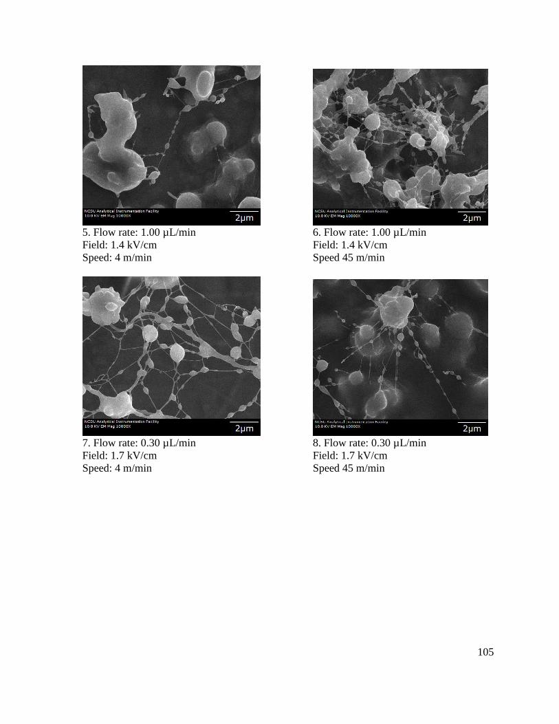
105
5. Flow rate: 1.00 µL/min 6. Flow rate: 1.00 µL/min
Field: 1.4 kV/cm Field: 1.4 kV/cm
Speed: 4 m/min Speed 45 m/min
7. Flow rate: 0.30 µL/min 8. Flow rate: 0.30 µL/min
Field: 1.7 kV/cm Field: 1.7 kV/cm
Speed: 4 m/min Speed 45 m/min

106
9. Flow rate: 0.50 µL/min 10. Flow rate: 0.50 µL/min
Field: 1.7 kV/cm Field: 1.7 kV/cm
Speed: 4 m/min Speed 45 m/min
11. Flow rate: 1.00 µL/min 12. Flow rate: 1.00 µL/min
Field: 1.7 kV/cm Field: 1.7 kV/cm
Speed: 4 m/min Speed: 45 m/min

107
13. Flow rate: 0.30 µL/min 14. Flow rate: 0.30 µL/min
Field: 1.9 kV/cm Field: 1.9 kV/cm
Speed: 4 m/min Speed: 45 m/min
15. Flow rate: 0.50 µL/min 16. Flow rate: 0.50 µL/min
Field: 1.9 kV/cm Field: 1.9 kV/cm
Speed: 4 m/min Speed: 45 m/min

108
17. Flow rate: 1.00 µL/min 18. Flow rate: 1.00 µL/min
Field: 1.9 kV/cm Field: 1.9 kV/cm
Speed: 4 m/min Speed: 45 m/min

109
All electrospun samples bore a very similar appearance on a microscopic level and all
appeared as a continuous sheet of a white fiber-web to the naked eye. The morphologies
comprised predominantly of beads, films and for certain conditions beaded fibers. Based on
subjective assessments of all the samples, the following observations could be made.
Increasing the speed of the collector drum from 4 m/min to 45 m/min resulted in more fibers
interconnecting the blotches or beads (e.g. Samples 11 and 12). This could presumably be
due to stretching of the beads under the action of the drag of the moving collector. Secondly,
fiber coverage per unit area increases as the flow rate increases (e.g. Samples 1, 3 and 5).
Thirdly, the size of beads or the coalescing of many beads reduces as the field increases (e.g.
Samples 2, 4 and 6).
Two notable samples from the above collection of electrospun samples were both found to
have a distinct morphology of uniform fibers. Sample 9 (Flow rate- 0.50 µL/min, Field- 1.7
kV/cm, Speed- 4 m/min) consists of uniform and continuous fibers, whereas, Sample 15
(Flow rate- 0.50 µL/min, Field- 1.9 kV/cm, Speed- 4 m/min) consists of beaded but thinner
fibers. The range of fiber diameter of Sample 9 was 170-250 nm, while that of Sample 15
was 30-50 nm. It was proposed that since these two samples contained fibers, they would
possess relatively higher surface area than the remaining from the set, and hence it may be
expected that they would exhibit antimicrobial effect. Therefore, both samples were tested
for antimicrobial activity by the AATCC standard method 100. Shown in Figure 21 are the
results of this evaluation.

110
(a) Control sample (b) Treated with Sample 9
(‘0’ contact time, No electrospun fibers) (contact time 24 hours, 370C)
(c) Treated with Sample 15
(contact time 24 hours, 370C)
Figure 21. (a-c) AATCC test method performed on Samples 9 and 15
Bacterial growth can be observed from the tiny yellow spots formed on the agar surface
overnight. Contrary to the expectation, the number of colonies visibly increased from the
‘control’ specimen to the ‘test’ specimens, such that it was not possible to manually count the
total number of colonies in each plate to determine percentage reduction/increase. However,
this was inconsistent with the observations made during the qualitative antimicrobial tests as

111
part of the preliminary work (Chapter 5, Section 5.1.4). It had been shown that increasing
amount of soy protein solution reduced the concentration of colonies. It may be noted that
this experiment had been done with purely denatured SPI solution and there was no PVA
mixed into it. This observation leads to the following possible inferences:
a) SPI/PVA fiber samples are conducive to the multiplication of bacteria
b) The fiberwebs did not contain adequate soy protein to be able to resist bacteria, hence
the results were not evident
c) The difference in structure (and therefore, molecular weight) of SPI solution and
SPI/PVA solution may have different interactions with bacteria.
Comparisons between the 2 test samples can also be made. It is quite evident that Sample 9
has a predominantly fibrous morphology compared to Sample 15 which has more of beads,
less fibers; though Sample 15 has a better fiber coverage per unit area than Sample 9. By
subjective analysis, Sample 15 shows marginally lower number of bacterial colonies than
Sample 9, which may indicate that the fiberweb produced by the parametric combination of
Sample 15 has greater exposed surface area of soy protein which may have prevented the
bacterial growth. To validate this hypothesis, it was necessary to find the chemical
composition of the beads and fibers by elemental analysis.
Elemental analysis by Electron Dispersive X-Ray Spectroscopy (EDS)
SEM images do not provide information about the chemical composition or chemical make-
up of the fibers formed from the homogeneous solution. This formulation contained SPI and
PVA which were uniformly blended in the solution form, but that does not ensure that they

112
remained so after extrusion from the needle until deposition. Hence, it would be vital to
perform an elemental analysis of the fibers and the beads in a particular sample to investigate
whether these structures contain only soy protein, or only PVA, or those containing both.
Furthermore, antimicrobial activity is expected of soy protein as it is known that PVA by
itself contains no antibacterial properties whatsoever. Therefore, for the fiberweb to be
effectively able to kill bacteria, the exposed surface area soy protein needs to be as high as
possible.
The EDS spectra of all samples distinctly display the presence of elements such as C and O
(polymeric materials), Al (foil material), Na (alkaline condition), Au/Pd (coating material).
SPI contains P in the ratio of 700-1000 mg/100g of soy which is found in the highest
concentration among all other minerals such as Na, Ca, Mg, Fe, etc. and hence was used as a
‘marker’ for soy protein. From the above spectra, the peak for P appears at the energy level
of 2.00 keV. For the beaded regions (Figure 22 a, b, c) and fiber regions (Figure 22 d) alike,
its peak is not clear or distinguishable and hence a definitive conclusion regarding the
presence of soy protein in these regions cannot be made. Moreover, it would not be possible
to substantiate the assumption that beaded regions contain more soy protein than individual
fibers.

113
Figure 22. (a-d) Elemental Analysis performed on samples 7, 11 and 18

114
(a) EDS Spectra of Sample 7

115
(b) EDS Spectra of Sample 11

116
(c) EDS Spectra of Sample 18 (bead)

117
(d) EDS Spectra of Sample 17 (small fiber)

118
The EDS spectra of all the electrospun structures display a common factor, which is the
indication of the presence of Aluminum. This was not an expected result as Al is the
substrate and the electrospun fibers are formed over the Al foil. The energies emitted or X-
rays detected and recorded are unique to every element which reflect as a unique peak in the
spectrum. The amplitude of the peak is an indication of this energy emitted and not
necessarily that of the percentage of the element in the focused area. Though, the electron
beam can be primarily made to focus on the highlighted region, it has an ‘interaction volume’
by virtue of which is penetrates through the structure as well as on the x-y plane. Any
element that falls within this limit and that is easily excited by the electron beam is part of the
detected X-rays. This is demonstrated in the simulation ‘Interaction Volume’ of Al (Figure
23) as substrate and C as layer of thickness 2 microns and acceleration voltage of 20 kV (this
was closest simulation of the polymeric sample of SPI/PVA which would contain maximum
C atoms). This showed that Al is almost equally excited by the electron beam as is C even
though it is 2 microns below the surface of C. Thus, it can be understood why the electrospun
fiber samples show presence of Al.

119
Figure 23. ‘Interaction Volume Simulation’ of C substrate on Al surface
The second notable observation from the experimental design is that Sample 9 and Sample
15 were clearly different in morphology from all the remaining samples, although they were
made from exactly the same composition of polymers and method of preparation. The greater
part of these two samples comprised of uniform fibers. Sample 9 and Sample 15 were
prepared using a relatively wider glass beaker, while the rest were prepared in a narrower
vessel. The greater surface area for evaporation enabled their respective solutions to achieve
a higher viscosity and hence resulted in fiber formation during electrospinning. This was
successfully validated when a replicate of Sample 9 was prepared in the wider vessel. What

120
may have caused this distinction is that Sample 9 was prepared in a different apparatus (4 cm
x 6 cm beaker) than Sample 15 (2.1 cm x 7 cm vial), all other conditions remaining same. To
validate this assumption, the two solutions were prepared again and electrospun individually
(all experimental conditions remaining same), this time in the two different apparatuses
mentioned above. The solution and fibers were characterized by viscosity measurement and
SEM. The SEM results of the fibers produced by electrospinning is shown in Figure 24.
(a) Apparatus: 2.1 cm x 7.0 cm beaker (b) Apparatus: 4.0 cm x 6.0 cm beaker
1.7 kV/cm, 0.50 µl/min, 4m/min speed 1.7 kV/cm, 0.50 µl/min, 4m/min speed
Viscosity: 33.94 centipoise Viscosity: 71.95 centipoise
Figure 24. (a-b) SEM images comparing morphology from 2 different viscosities
The SEM images of the 2 samples when observed at 2000x magnification clearly indicates
that on increasing solution viscosity the morphology shifts from beads to fibers. At a
viscosity of 33.95 cP the structure consisted predominantly of beads. While, at a higher

121
viscosity of 71.95 cP, there is a uniform thin network of fibers that appears as a white sheet
on a macroscopic level.
On closer observation of sample shown in Figure 24 (b), there were many other interesting
features. Some parts of the fiberweb was made of a bunch of fibers fused together. A
distinctive characteristic of these bunches were ‘spiky’ projections that seemed to originate
from a common base or point. Figure 25 shows these ‘spikes’ at a higher magnification
appearing as bright spots and their corresponding elemental analysis by EDS in Figure 26.
Interestingly, the unusual ‘spiky’ structures displayed a prominent peak for ‘P’ suggesting a
strong presence of soy protein in the regions where they were found.

122
(a) (b)
(c)
Figure 25. The electrospun ‘spikes’ appeared brighter than the remaining parts of the fiber-
web of fibers and beads
The EDS spectra was collected from several regions of the above sample due to specific
features such as individual fibers, ‘spiky’ structures, and fused fiber bunches (Figure 26).

123
Figure 26. (a-c) Elemental Analysis of sample shown in Figure 25

124
(a) EDS Spectra of feature S1- ‘spiky’ structure

125
(b) EDS Spectra of feature S2 – ‘single fiber’

126
(c) EDS Spectra of ‘spiky’ structure in highlighted portion

127
When the electron beam was made to focus on a single random fiber, the EDS displays very
weak energies for C and O. Individual fibers are thin and the energies are collected from a
volume surrounding the fiber, thus diluting the specific elemental energies radiated from the
fiber alone. Due to this, there was no peak for ‘P’ found with respect to the single fiber. On
the other hand, the unusual ‘spiky’ structures displayed a prominent peak for ‘P’ indicating a
strong presence of soy protein in the regions where these ‘spikes’ were found. The height of
this peak can be compared to those observed for the beads in the experimental design
samples, which were not distinguishable and were flatter in appearance. Therefore, it may be
understood that, the ‘spikes’ were formed mainly of soy protein.
The formation mechanism of these ‘spikes’ cannot be concluded, but a possible hypothesis
can be discussed here. Incomplete evaporation of the solvent (water) may have caused
diffusion of individual fibers, as the ‘spikes’ only appear on fiber bunches and not on single
uniform fibers. Each ‘spike’ seems to be originating from a common base as it appears
tapering towards the end. When the needle extrudes the polymeric solution it is positively
charged until the solvent evaporates and the fibers reaches the earthed end and settles on the
collector. However, in the presence of a non-volatile solvent such as water and a less viscous
solution, collection may be in the form of beads instead of fibers. These beads may contain
some residual solvent which now is negatively charged on account of being at the grounded
collector. As a result, an electric field is set up between the positively charged needle and the
negatively charged bead. Such an occurrence may have caused fibers to now, originate from
the negative to the positive potential. Since, the collector is continuously rotating at high
speed, the numerous spikes may have stemmed from a single bead after several cycles of

128
rotation. In presence of a volatile solvent system, complete evaporation might have occurred,
which would have not left traces of solution on the collector. However, in presence of water,
the installation of a heating system in the electrospinning set-up may be an effective method
to facilitate its evaporation. In this way, the heat could evaporate even the trace solvent from
the extruded fibers and minimize the occurrence of fibers sticking to one another.
To further investigate the nature of these ‘spikes’, their antimicrobial property was evaluated.
The sample from Figure 25 was tested for antimicrobial activity by employing the AATCC
standard test method 100. The prominent proportion of soy protein in the morphology was
expected to produce the desired antimicrobial effect that the previous set of samples failed to
show. Figure 27 shows images of the antimicrobial tests conducted on the sample containing
‘spikes’.

129
(a) Untreated, before incubation (b) Untreated, 24 h incubation
(c) Treated, 24h incubation- I (d) Treated, 24h incubation- II
Figure 27. Results of AATCC test 100 conducted on samples shown in Figure 25
Figure 27 a shows the plated agar before it was incubated in the oven overnight. Figure 27 b
shows the untreated ‘control’ plate after 24 hours of incubation at 300C. Figure 27 c and
Figure 27 d are 2 replicates of the treated samples after incubation. Control sample contained
no soy protein, and hence no potential antibacterial agent, and grew a film of bacterial
colonies over the agar. However, contrary to expectation, the plates containing the solution
eluted from the electrospun fiberwebs showed a distinct increase in the concentration of
bacterial colonies. It is not possible to distinguish one colony from another since they are
very densely spread out, thus forming a film. These images may also be compared with the

130
results obtained from samples containing beads. It leads to the assumption that though more
surface soy protein was detected in the above fibrous sample, the bacterial growth becomes
more rapid.

131
6 Conclusions
Soy protein in the form of soy protein isolate (SPI) was successfully incorporated into a
formulation with a suitable grade of PVA. 5 different grades of PVA (based on mol. wt. and
percentage of hydrolysis) were tested for ‘electro-spinnability’ along with SPI. It was found
that T-66 PVA from DuPont™ was found to resist transformation into gel for a prolonged
period and the molecular weight allowed achievement of suitable spinning viscosity. From
the various mass ratios of SPI and PVA prepared it was found that increasing SPI
concentration in the formulation decreased viscosity resulting in mere spraying of solution,
while increasing ratios of PVA increased final viscosity resulting in continuous fiber
formation. 50:50 mass ratio was concluded as the optimum as it had the maximum
achievable SPI and was also capable of fiber formation. This formulation was subjected to 18
different treatment conditions of parameters such as electric field (kV/cm), flow rate (µl/min)
and collector speed (m/min). Results from SEM characterization showed that all produced
very similar kind of morphology of beads and beaded fibers except for one that produced a
uniform network of fibers. Each of these distinct morphologies was tested for antimicrobial
activity. Bacterial growth was seen nevertheless for both fibers and beads and hence it was
difficult to draw conclusions regarding the potential of these structures to kill bacteria.
Decreasing bacterial growth was however noticed when SPI alone was used as the ‘active
ingredient’ in the test method.
To test the repeatability of fiber-producing solution viscosity, the SPI/PVA formulation was
re-prepared using a wider beaker allowing for greater evaporation of solvent, thus resulting in

132
higher viscosity. SEM results revealed that not only were the fibers continuous and devoid of
beads, but portions showing diffused (or bundled) fibers contained ‘spiky’ structures with
projections appearing like tapering ‘spikes. Elemental analysis revealed that these unique
structures contained higher amount of SPI than the rest of the sample. However, once again
when tested for antimicrobial activity, on subjective analysis of the bacterial growth, there
seemed to be an increase rather than a decrease in bacterial population. Bacterial colonies
decreased with increasing amount of SPI solution. In contrast, they increased in presence of
SPI/PVA fibers. SPI/PVA fibers proved to be a conducive environment for the growth of
bacteria, though SPI did not, possibly due to the change in molecular interactions between
denatured SPI and PVA, resulting in increase in molecular size.
Recommendations for Future Work
This work has confirmed that SPI and PVA are a good combination for producing
electrospun structures with a wide range of morphologies. Though, further research would be
required to explore the answers for certain questions that the findings from this work present.
(1) It would be worthwhile to develop a solvent system and preparation method for Chitosan-
Soy fibers. Chitosan-Soy is a promising economical blend of materials to produce
antimicrobial fibers. Antimicrobial activity of chitosan is already well established and soy
protein may be successfully incorporated to offset the cost attached with chitosan and its
derivatives.

133
(2) Soy protein isolate drawn into films from aqueous solution could be tested for
antimicrobial activity. Previous work in this field has shown that soy protein isolate films
have adequate mechanical strength, flexibility and translucency. The incorporation of
PVA may as well be eliminated if such films can equally efficiently kill bacteria.
(3) Unusual ‘spiky’ morphologies have not been reported in electrospinning of SPI/PVA. It
would be valuable to explore their formation mechanism, properties and whether they can
be reproduced. Additionally, to facilitate evaporation of the solvent (water), a heater
system may be incorporated in the set-up in order to avoid formation of smaller electric
fields due to presence of water in between the needle and collector. This will also lead to
avoiding fiber bundle formation, which is undesirable as it reduces fiber surface area.
(4) It has not been reported till date the mechanism of how soy protein and bacteria interact.
Deeper understanding of the surface chemical/physical interactions between bacteria and
soy protein polymers would clear the pathway for setting further goals in this area.

134
7 References
[1] Bharadwaj, Nandana, and Subhas C. Kundu. "Electrospinning: a Fascinating Fiber
Fabrication Technique."Biotechnology Advances 28(2010): 325-347. Print.
[2] Teo, Wee-Eong. "Technological Advances in Electrospinning of Nanofibers." Science
and Technology of Advanced Materials 12(2011): 1-19. Web. Feb. & March 2012.
[3] Huang, Zheng-Ming. "A Review on Polymer Nanofibers by Electrospinning and Their
Applications in Nanocomposites."Composites Science and Technology 63(2003): 2223-
2253. NCSU Libraries. Web. Apr. 2012.
[4] Jian, Fang et al. "Applications of Electrospun Nanofibers." Chinese Science Bulletin
53.15 (2008): 2265-2286. Web. Feb. 2012.
[5] Lysons, Jason, and Jim Kaufmann. "Electrsospinning: Past, Present & Future." Textile
World Aug. 2004. 41-48.NCSU Libraries. Web. Feb. 2012.
[6] Doshi, Jayesh, and Darrell H. Reneker. "Electrospinning Process and Applications of
Electrospun Fibers." Journal of Electrostatics 35(1995): 151-160. Web. Jan. & Feb.
2012.
[7] Li, Dan, and Younan Xia. "Electrospinning of Nanofibers: Reinventing the
Wheel?" Advanced Materials 16.14 (2004): 1151-1170. Web. Jan. & Feb. 2012.
[8] Frenot, Audrey. "Polymer Nanofibers Assembled by Electrospinning." Current Opinion
in Colloid and Interface Science 8(2003): 64-75. NCSU Libraries. Web. May 2013.

135
[9] Thoppey, Nagarajan M. "Unconfined Fluid Electrospun into High Quality Nanofibers
from a Plate Edge." Polymers 51(2010): 4928-4936. NCSU Libraries. Web. Mar. 2012.
<http://www.sciencedirect.com/science/article/pii/S0032386110006592>.
[10] Schiffman, Jessica D. and Caroline L. Schauer. "A Review: Electrospinning of
Biopolymer Nanofibers and Their Applications." Polymer Reviews 48(2008): 317-352.
NCSU Libraries. Web. Jan. & Feb. 2012.
[11] Hussain, D., F. L. Loyal, A. Greiner, and J. H. Wendorff. "Structure Property
Correlations for Electrospun Nanofiber Nonwovens." Polymer 51(2010): 3989-3997.
Web. Jan. & Feb. 2012.
[12] Agarwal, Seema et al. "On the Way to Clean and Safe Electrospinning—green
Electrospinning: Emulsion and Suspension Electrospinning." Polymers Advanced
Technologies 22(2011): 372-378. Web. Apr. 2012.
[13] Reddy, Narendra, and Yiqi Yang. "Potential of Plant Proteins for Medical
Applications." Trends in Biotechnology 29.10 (2011): 490-498. Web. NCSU Libraries.
& Feb. 2012.
[14] Reddy, Narendra, and Yiqi Yang. "Soyprotein Fibers with High Strength and Water
Stability for Potential Medical Applications." Biotechnology Progress 25.6 (2009):
1796-1802. NCSU Libraries. Web. Jan. & Feb. 2012.
[15] Jacobs, Valencia, Asis Patanaik, Rajesh D. Anandjiwalaa, and Malik Maaza.
"Optimization of Electrospinning Parameters for Chitosan Nanofibers." Current
Nanoscience 7.3 (2011): 396-401. Web. Jan. 2012.

136
[16] Seyam, Abdel-Fattah M., Sam M. Hudson, Hassan M. Ibrahim, Ahmed I. Waly, and
Nabil Y. Abou-Zeid. "Healing Performance of Wound Dressing from Cyanoethyl
Chitosan Chitosan-based Electrospun Fibers." Indian Journal of Fiber & Textile
Research 37(2012): 205-210. Print.
[17] Zhong, Wen. "Nanofibrous Materials for Wound Care." Cutaneous and Ocular
Toxicology 29.3 (2010): 143-152. Web. Feb. 2012.
[18] Chen, Guanfushou, and Haiqing Liu. "Electrospun Cellulose Nanofiber Reinforced
Soybean Protein Isolate Composite Film." Journal of Applied Polymer
Science 110(2008): 641-646. Web. Feb. 2012.
[19] Jayakumar, R., M. Prabaharan, P.T. Sudheesh Kumar, S. V. Nair, and H. Tamura.
"Biomaterials Based on Chitin and Chitosan in Wound Dressing
Applications." Biotechnology Advances 29(2011): 322-337. Web. Jan. & Feb. 2012.
[20] Zi, Teng. "Nanoparticles Synthesized from Soy Protein: Preparation, Characterization,
and Application for Nutraceutical Encapsulation." Journal of Agriculture and Food
Chemistry 60(2012): 2712-2720. Web. Apr. 2012.
[21] "Super Soy! Medical Uses for Soy Compounds May Be on the Horizon." United States
Department Of Agriculture, Agricultural Research Service. United States Department
of Agriculture, 10 Jan. 2006. Web. Jan. 2012.
[22] Silva, S. S., M. I. Santos, O. P. Coutinho, J. F. Mano, and R L. Reis. "Physical
Properties and Biocompatibility of Chitosan/soy Blended Membranes." Journal of
Materials Science: Materials in Medicine 16(2005): 575-579. Web. Jan. 2012.

137
[23] Vega-Lugo, Ana-Cristina, and Loong-Tak Lim. "Electrospinning of Soy Protein Isolate
Nanofibers." Journal of Biobased Materials and Bioenergy 2.3 (2008): 223-230. NCSU
Libraries. Web. Jan. & Feb. 2012.
[24] Cho, Daehwan , Olivia Nnadi, Anil Netravali, and Yong Lak Joo. "Electrospun Hybrid
Soy Protein/PVA Fibers."Macromol. Mater. Eng 295(2010): 763-773. NCSU Libraries.
Web. Jan. 2012.
[25] "Soy Protein Isolates." Center for Crops Utilization Research. Iowa State University,
2008. Web. Apr. 2013. <http://www.ccur.iastate.edu/samplecards/oilseeds/227.pdf>.
[26] Sinha-Ray, S. et al "Solution Blowing of Soy Protein
Fibers." Biomacromolecules 12(2011): 2357-2363. NCSU Libraries. Web. Mar. 2013.
[27] Swain, S. N. et al "Biodegradable Soy-Based Plastics: Opportunities and
Challenges." Journal of Polymers and the Environment 12.1 (2004): 35-42. NCSU
Libraries. Web. Apr. 2013.
[28] "Pro-Fam® 974." Archer Daniels Midland Company. N.p., 2013. Web. Mar. 2013.
<www.adm.com/_layouts/pdf.aspx?techdocid=5485&src=E>.
[29] Endres, Joseph G. "Functionality of Soy Proteins." Soy Protein Products
Characteristics, Nutritional Aspects, and Utilization. Champaign, IL: AOCS Press,
2001. 26-30. NCSU Libraries. Web. Apr. 2013.
[30] Srinvasan, Gowrishankar. “Soy protein polymers: Enhancing the water stability
property” MS Thesis Iowa State University, 2010. Web. 17 April 2013.
[31] Lodha, Preeti, and Anil Netravali. "Thermal and Mechanical Properties of
Environment-friendly ‘green’ Plastics from Stearic Acid Modified-soy Protein

138
Isolate." Industrial Crops and Products 21(2005): 49-64. NCSU Libraries. Web. March
& April 2013.
[32] Xu, Qingyi. "Soybean-based Surfactants and Their Applications." Soybean -
Applications and Technology. InTech, 2011. N. pag. INTECH. Web. Apr. 2013.
<http://www.intechopen.com/books/soybean-applications-and-technology>.
[33] Zhang, L, and M Zeng. "Proteins as Sources of Materials." Monomers, Polymers and
Composites from Renewable Resources. UK: Elsevier, 2011. 480+. Google Books.
Web. Apr. 2013. <http://books.google.com/books?id=N-
byhCZyTn0C&printsec=frontcover&source=gbs_ge_summary_r&cad=0#v=onepage&
q&f=false>.
[34] Delia. "Effects of Thermal Treatment of Soy Protein Isolate on the Characteristics and
Structure-Function Relationship of Soluble and Insoluble Fractions." J. Agric. Food
Chem 43(1995): 2471-2479. NCSU Libraries. Web. Apr. 2013.
[35] Varzakas, T. "Rheological Properties of a Soy Protein Isolate and Concentrate: Effect
of Gel Strength." International Congress of Engineering and Food (2011): N. pag.
Web. Apr. 2013. <http://www.icef11.org/content/papers/fms/FMS783.pdf>.
[36] Fung, Wai-Yee. "Agrowaste-Based Nanofibers as a Probiotic Encapsulant: Fabrication
and Characterization." J. Agric. Food Chem. 59.15 (2011): 8140-8147. NCSU
Libraries. Web. Mar. 2012.
[37] Rijavec, Tatjana, and Ziva Zupin. "Soybean Protein Fibers (SPF)." Recent Trends for
Enhancing the Diversity and Quality of Soybean Products. InTech, 2011. 501-522.
Soybean Protein Fibers (SPF) | InTechOpen. Web. Feb. 2012.

139
[38] Zhang, Yi, S. Ghasemzadeh, Abraham M. Kotliar, Steven Presnell, Loren D. Williams,
And Satish Kumar. "Fibers From Soybean Protein And Polyvinyl alcohol." Journal Of
Applied Polymer Science, 71(1999): 11-19. Web. Jan. 2012.
[39] Zhang, Xiefei, Byung G. Min, and Satish Kumar. "Solution Spinning and
Characterization of Poly(vinyl Alcohol)/Soybean Protein Blend Fibers." Journal of
Applied Polymer Science 90(2003): 716-721. Web. Jan. & Feb. 2012.
[40] Su, Jun-Feng, Zhen Huang, Chuan-Min Yang, and Xiao-Yan Yuan. "Properties of Soy
Protein Isolate/Poly(vinyl Alcohol) Blend ‘‘Green’’ Films: Compatibility, Mechanical
Properties, and Thermal Stability." Journal of Applied Polymer Science 110(2008):
3706-3716. Web. Jan. 2012.
[41] Santos, Tircia C. "Chitosan Improves the Biological Performance of Soy-Based
Biomaterials." Tissue Engineering: Part A 16.9 (2010): 2883-2890. Web. Jan. 2012.
[42] Blitterswijk, Clemens A. "Chapter 6 Natural Polymers in Tissue Engineering
Applications." Tissue Engineering.Burlington, MA, USA: Academic Press, 2008.
175. NCSU Libraries. Web. Mar. 2012.
[43] Nawalakhe, R., (2009), Master’s Thesis, Improving Healing Performance of wound
dressing: electrospinning of chitosan-based, cellulose-based fibers and their blends,
NCSU Libraries. Web. Feb. 2012 (under direction of Drs. Abdel-Fattah M. Seyam and
Samuel Hudson).
[44] Nawalakhe, R., A.M Seyam, and S. Hudson. "Development of Electrospun
Iminochitosan for Improved Wound Healing Application." Journal of Engineered
Fibers and Fabrics 7.2 (2012): 47-55. NCSU Libraries. Web. Jan. 2013.

140
[45] Khansari, S. et al. "Stress-strain Dependence for Soy-protein Nanofiber Mats." Journal
of Applied Physics 111.044906 (2012): N. pag. Print. May 2012.
[46] Ramachandran, Rohit. "A Mechanistic Model for Breakage in Population Balances of
Granulation: Theoretical Kernel Development and Experimental Validation." Chemical
Engineering Research and Design 87(2009): 598-614. NCSU Libraries. Web. June
2013.
[47] Feng, Quan Et Al. "Preparation of a Cu (II)-PVA/PA6 Composite Nanofibrous
Membrane for Enzyme Immobilization."Int. J. Mol. Sci. 13(2012): 12734-12746. Web.
June 2013.
[48] Liu, Dagang et al. "Facile Preparation of Soy Protein/Polyvinyl alcohol Blend Fibers
with High Mechanical Performance by Wet-Spinning." Industrial & Engineering
Chemistry Research 52(2013): 6177-6181. ACS Publications. Web. June 2013.
<http://pubs.acs.org/journal/iecred>.
[49] Dosako, Shunichi et al. "Changes in Rheological and Chemical Properties of Soy
Protein Dope Solution through Increase of Aging Time." Agric. Biol. Chem. 43.4
(1979): 809-814. NCSU Libraries. Web. June 2013.
[50] Wang, Hualin. "Fabrication and Characterization of PVA/SPI/SiO2 Hybrid Fibers via
Electrospinning Technique." Polymers & Polymer Composites 20.7 (2012): 621-
627. NCSU Libraries. Web. Apr. 2013.
[51] Pankey, G A., and L D. Sabath. "Clinical Relevance of Bacteriostatic Versus
Bactericidal Mechanisms of Action in the Treatment of Gram-Positive Bacterial
Infections." Clinical Infectious Diseases 38.6 (2004): 864-870. NCSU Libraries. Web.
July & Aug. 2013.

141
[52] A. Varesano, C. Vineis, A. Aluigi, F. Rombaldoni, "Antimicrobial polymers for textile
products". In: A. Méndez-Vilas (Ed.), "Science against Microbial Pathogens:
Communicating Current Research and Technological Advances", Formatex,
Microbiology Series Nº3, Vol. 1, Badajoz, Spain, pp. 99–110 (2011). ISBN-13: 978-
84-939843-1-1.
[53] Timofeeva, Larisa, and Natalia Kleshcheva. "Antimicrobial Polymers: Mechanism of
Action, Factors of Activity, and Applications." Appl Microbiol Biotechnol 89(2011):
475-492. NCSU Libraries. Web. July & Aug. 2013.