abstract - solid freeform fabrication symposium · abstract . this paper describes ... cladding,...
TRANSCRIPT

Cladding and Additive Layer Manufacturing with a laser supported arc process
A. Barroi, J. Hermsdorf, R. Kling
Laser Zentrum Hannover e.V., Hannover, 30419, Germany
Abstract
This paper describes the potential of a new process, combining the geometrical
precision of a laser technique and the deposition rates of GMA cladding. Dilutions as low
as 3 % can be achieved, leading to a high purity, in the first layer. Different material
combinations like mild steel with X45CrSi9-3 are presented. Microsections for
penetration depth determination show the high quality of the deposition layers. A
hardness of the coatings of 63 HRC is reached. Hardfacing of shafts serve as an
application example. The low heat input enables the process to build up structures. This
results in a process variant for additive layer manufacturing which is also presented. The
production of macro-sized structures is shown and discussed.
Introduction
Metal deposition techniques are used for cladding and form fabrication. Both
applications deposit in layers, which are formed by single seams that are welded to the
underlying surface. In cladding these seams are welded directly next to each other with a
slight overlap. This forms an even surface. In Additive Layer Manufacturing (ALM)
more complex geometries need to be handled and the process requires higher
controllability. This controllability relates to switching the process on and off. A gap in
the component can be produced when the process is switched off and a deposit is made
when switched on. Using this method a component is built on a substrate. The substrate
material can be the same as the deposition material, especially if the substrate is part of
the component. If not it can be a cheap, easy to weld material which is removed
afterwards. In cladding, where functional coatings are applied to workpieces, the
materials differ. Another distinction of metal deposition techniques is the size of the
components. In this work a new technique will be presented. It is suited for cladding and
has the potential for fabrication, in both cases in the macro regime.
Macro sized claddings and fabrications are presently done by various techniques.
Plasma Transferred Arc for example is a process which provides extremely high
deposition rates, but has rather high dilutions of 5-20 % [1]. Another technique is laser
cladding, where high precision and almost no dilution are reached. The major drawback
is the need for high-power laser systems and the accompanying high costs. An approach
to reduce these costs is Plasma Augmented Laser Cladding. Here, plasma is used to heat
the deposition powder just below its melting temperature. A setback is the rather low
deposition rate [2].
Form fabrication experiments with gas metal arc welding (GMAW) and gas
tungsten arc welding (GTAW) have been performed by Almeida et al. They were
conducted with a titanium alloy as fabrication material. Applying the GTAW process,
1000 x 200 mm structures were built. The setback is the low deposition rate and a high
164

heat input. Due to this heat input, the workpiece has to cool down to room temperature
after each layer, resulting in a slow process. Cold Metal Transfer (CMT), a GMAW
process with less heat input, has also been tested. The process uses a controlled current
and a forward/backward oscillation of wire which is superimposing the wire feed.
Despite this control the results with CMT show high penetration depth of around 2 mm
[3]. To overcome this setback a laser enhanced cold GMAW process is used. The
presented technique involves a GMA welding machine and a diode laser. The laser
radiation is used for stabilization and guidance of the electric arc. Therefore, it is tuned to
a wavelength of 811 nm by means of diode temperature control [4,5,6].
Experimental
The setup is composed of a Merkle welding machine with ColdMIG technology.
The torch is at an angle of 60° in the pushing direction. A 500 W direct-diode laser, with
the beam inciding perpendicular to the workpiece (Fig. 1, 2), is used in order to stabilize
the arc plasma. The laser is pointing in front of the wire tip, with a slight overlap, to
ensure that the laser radiation can interact with the plasma without melting the wire.
Fig. 1: Sketch of setup alignment
Fig. 2: Setup realization
Cladding of Layers
For the cladding experiments, two different material combinations are used.
Combination A consists of structural or mild steel as base material and 1.8401, a wear
resistant steel, as deposition material. In combination B, 1.4718 hardfacing steel is used
as deposition material and mild steel as substrate.
Experiments with material combination A are performed on sheet metal.
Therefore, an axis system is used to move the welding torch and the laser over the
workpiece. After each seam, the welding head is moved back and aside by an offset sv in
order to create a layer (Fig. 3). The seam offset is fitted to the track width br in order to
achieve an even surface.
165

The same principle is used for the hardfacing of shafts. A combination of a
rotational axis and a linear axis is used to apply the deposition material as a single, helix
type seam. The speed of the linear axis is matched to the rotation so that after each full
turn the desired seam offset sv is reached.
The important process parameters are the base current Ig, the lower limit current Ia
and the average voltage U which the welding machine tries to maintain. Furthermore, the
ratio of the wire feed rate WFR and the feed rate of the axis system FR determine the
height and the width of the seam. In all experiments a mixture of Argon and 18 % CO2
has been used as shielding gas.
Additive Layer Manufacturing
In the ALM or form creation experiments, bar-like structures are produced using
the 1.8401 steel. The mild steel substrate is not meant to be a part of the component in
our tests. Its function is to carry the generated structure. The seam offsets in these
experiments are perpendicular to the sheet plane and are determined by the thickness of
the previous layer. They describe how much the welding head is lifted after a layer is
welded. Therefore, in the first experiments, the height of the structure is measured after
each layer.
Experimental Results
The experiments show promising results in the cladding and the ALM process.
With the same setup, it is possible to create protective coatings and to fabricate simple
structures.
Results of Cladding
The cladding experiments are performed in order to create a functional coating on
a substrate with as little mixture of the materials and as low heat input as possible. For the
material combination A, low currents together with a high welding speed show very little
dilution.
Fig. 3: Geometrical layer parameters
166

Table 1: Parameters for sheet coating
parameter Ig Ia U WFR FR sv
value 50 A 20 A 17 V 3 m/min 1.1 m/min 1.3 mm
Fig. 4: Low dilution of base and deposition material
Fig. 4 shows a cross section of a layer produced by these parameters (Table 2).
Due to the low penetration depth of 0 mm to 0.17 mm, the dilution is very low and partly
there is no welded bond. The high purity of the coating leads to a hardness of around
370 HV (approx. 38 HRC).
An extreme pushing angle of the GMA torch shows good results. Fig. 5 depicts a
cross section of a layer obtained by this parameter set (Table 2). For a good welding
quality at that torch angle, more power in the electric arc is needed. The progression of
the penetration depth in the cross section shows a wavy behavior. This leads to pores on
the substrate coating boundary at the interface of the welding seams. The coating does
not show pores in the volume. The reached dilution of about 10 % is higher compared to
the previous shown results, but the surface has a better quality.
Table 2: Parameters with extreme pushing angle of GMA torch
parameter Ig Ia U WFR FR sv torch angle
value 80 A 40 A 11 V 3 m/min 1.5 m/min 1.25 mm 30 °
Fig. 5: Low dilution and even surface with material combination A
167

Experiments with the parameter set in Table 3, using material combination B,
result in a coating that is properly welded to the substrate, but has some pores between
the seams at the substrate boundary (Fig. 6). The welding speed for the first seam was
raised to lower the penetration depth. Despite this measure, it is still higher compared to
the following seams. The dilution of the coating is as low as 3 %, with about 9 % dilution
in the region of the first seam and less than 2 % in the rest of the coating. This high purity
of the layer leads to a hardness with an average of 63 HRC.
Table 3: Hardfacing parameters for material combination B on sheet metal
parameter Ig Ia U WFR svFR, first
seam
FR, following
seams
value 85 A 60 A 19.5 V 2.9 m/min 2.5 mm 0.6 m/min 0.4 m/min
Fig. 6: Cross section of material combination B
A transfer of the results from sheet metals to shafts is reached with nearly the
same parameters (Table 4). A decrease of the voltage and the seam offset in addition to a
slower feed rate of 0.4 m/min leads to an even surface (Fig. 7) and a properly welded
deposit (Fig. 8). The hardness of the coating is high at an average of 63 HRC which
provides excellent wear protection.
Table 4: Parameters for shaft cladding
parameter Ig Ia U WFR sv FR
value 85 A 60 A 17.2 V 2.9 m/min 2.25 mm 0.4 m/min
168
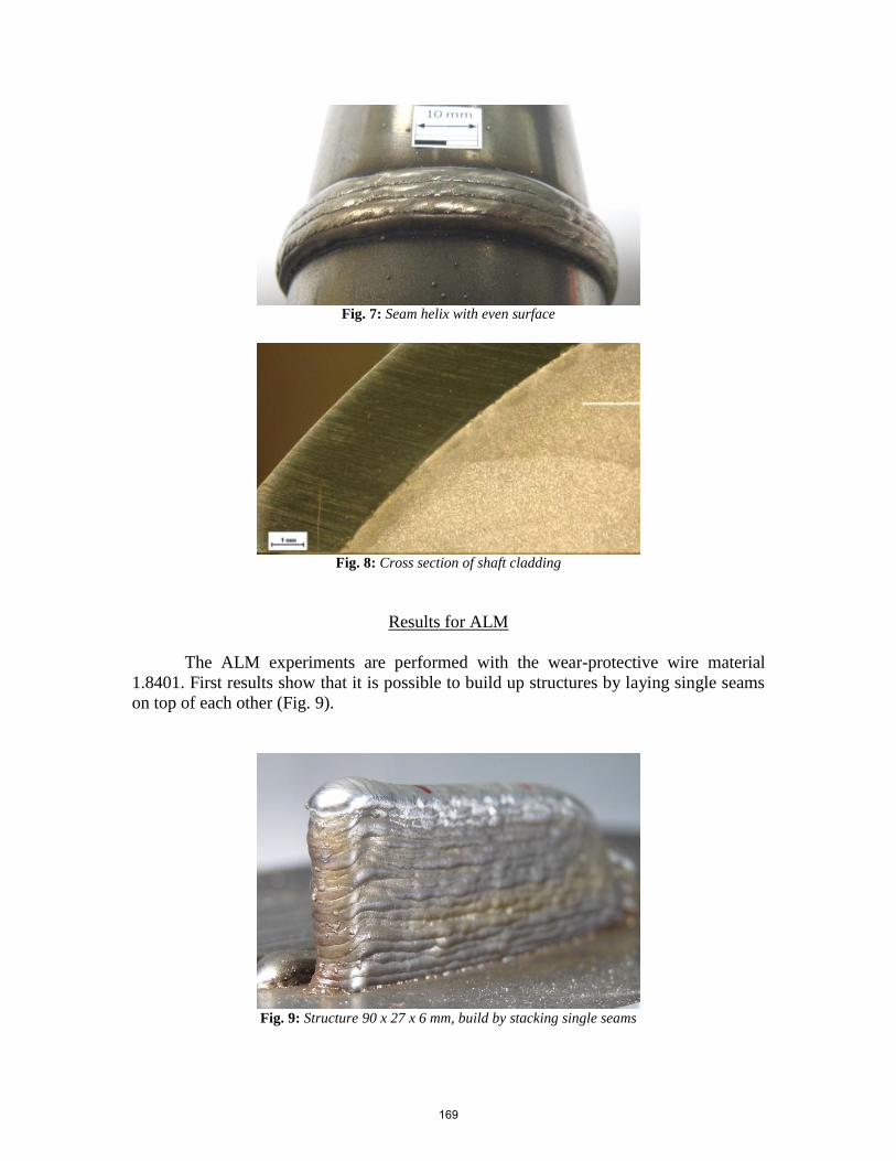
Fig. 7: Seam helix with even surface
Fig. 8: Cross section of shaft cladding
Results for ALM
The ALM experiments are performed with the wear-protective wire material
1.8401. First results show that it is possible to build up structures by laying single seams
on top of each other (Fig. 9).
Fig. 9: Structure 90 x 27 x 6 mm, build by stacking single seams
169

In these first tests it was already possible to reach an aspect ratio of the structure
of 4:1. The results do not indicate a limitation for increasing this ratio. The heat flow
from the welding area on top of the structure towards the substrate does not seem to
decrease below a critical amount with the height of the fabricated component.
The laser improves the process significantly. Fig. 10 shows a comparison of two
structures. The structure on the left has been produced without laser stabilization and the
structure on the right with laser stabilization. A significant misalignment of the seams
results from this lack of stabilization. An evenly erected layer-system is produced with
the laser enhanced process. We assume that the laser helps to maintain the melting pool
in the middle of the seam. Therefore, the melting is distributed evenly and does not flow
exceedingly to one side.
Fig. 10: Comparison of structures built with laser
stabilization (right) and without (left)
To build this structure we measured the height after welding each layer. This
information is used to determine the correct height offset of the welding head for the next
layer. To overcome the additional time needed for this measuring step we have analyzed
the progression of the height of the structure with each layer. A linear fit to the resulting
graph Fig. 11 shows very little deviation. Therefore, a fixed height offset was tested in
later experiments.
170

Fig. 11: Linear progression of the structural height with each layer
As can be seen in Fig. 12 problems arise at the beginning and the end of the
structure when welding in only one, here pushing, direction. The middle of the structure
shows a constant height, but since there is too much material at the beginning a build-up
accumulates. The opposite is happening at the end of the welds. Not enough material is
deposited and leads to a downward ramp that grows towards the middle of the structure
with each layer.
Fig. 12: Deposit build-up at beginning and lack of material at end of structure
The simplest way to correct for the volume issue at the beginning and the end of
the structure is to weld bi-directionally. One problem is the non-symmetrical setup of the
GMA torch. In previous experiments the change of the seam quality depending on the
welding direction has been shown [7]. These tests have been repeated with at a slower
welding speed. In Fig. 13, the seam quality, related to the welding direction, is compared.
The dragging direction shows a distorted surface, whereas the surface in the pushing
direction is smooth.
171
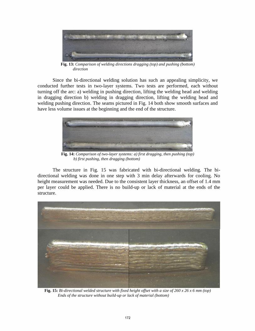
Fig. 13: Comparison of welding directions dragging (top) and pushing (bottom)
direction
Since the bi-directional welding solution has such an appealing simplicity, we
conducted further tests in two-layer systems. Two tests are performed, each without
turning off the arc: a) welding in pushing direction, lifting the welding head and welding
in dragging direction b) welding in dragging direction, lifting the welding head and
welding pushing direction. The seams pictured in Fig. 14 both show smooth surfaces and
have less volume issues at the beginning and the end of the structure.
Fig. 14: Comparison of two-layer systems: a) first dragging, then pushing (top)
b) first pushing, then dragging (bottom)
The structure in Fig. 15 was fabricated with bi-directional welding. The bi-
directional welding was done in one step with 3 min delay afterwards for cooling. No
height measurement was needed. Due to the consistent layer thickness, an offset of 1.4 mm
per layer could be applied. There is no build-up or lack of material at the ends of the
structure.
Fig. 15: Bi-directional welded structure with fixed height offset with a size of 260 x 26 x 6 mm (top)
Ends of the structure without build-up or lack of material (bottom)
172

Conclusion and Outlook
We have shown that the laser assisted process can be applied in cladding and also
has the potential to be used in ALM. In cladding, it is possible to weld at high speed and
low power. This results in a low dilution, little heat input and a high hardness, due to the
purity of the deposit.
First tests have been performed in order to reduce the penetration depth and
therefore the dilution to a minimum. The penetration depth is lowered that far, that there
is almost no dilution with the parameters shown in Table 1. An average hardness of
370 HV (approx. 38 HRC) was reached in the coating. The setback with these parameters
is the bonding. In the middle of each seam, the materials are welded but in between there
is no strong bond.
Tests with an extreme pushing angle (Fig. 5) lead to an even surface of the
coating. The dilution is around 10 % due to the higher current that has been used. The
few pores on the substrate coating boundary are small and should not have a negative
influence on the quality of the layer, due to the properly welded bond. A setback of the
extreme pushing angle is that it limits the setup’s use in automated cladding of 3D
contours due to a reduced free angle between workpiece and process head.
The experiments with material combination B are performed with adjusted
parameters (Table 3). There is a welded bond of the deposit and the substrate. Only in the
seam-to-seam interface are there pores at the substrate boundary level. These will be far
away from the surface after the finishing of the coating with grinding. The hardness of
the deposit is measured with an average of 63 HRC providing a strong wear protection. A
high purity of the layer is reached due to the dilution of only about 3 %. The first welded
seam on the right side of the cross section (Fig. 6) shows a higher penetration depth. This
is typical for starting seams and is already reduced by a 50 % higher welding speed as
compared to the welds done previously. Therefore, the dilution in this region is higher at
about 9 %, whereas the dilution of the following seams is less than 2 %. With slightly
adjusted parameters (Table 4), it is possible to hardface shafts with helix type welding
seam, reaching similar results as on the sheet metal.
The achieved coatings are highly pure, so one layer will be sufficient where often,
with conventional processes, two or more layers were needed. No pre-heating of the
substrate is needed and the deposit reaches very high hardness for excellent wear
protection.
Future steps will be to investigate the 3D ability of the process. Therefore,
experiments in different welding positions need to be performed. Furthermore, a laser
based adaption of the power distribution in the arc could lead to an evenly penetration
depth, elimination of pores at the intersection of the seams and the substrate boundary.
The ALM experiments show that the laser enhancement has advantages in the
generation of structures. We assume that the laser helps to keep the melting pool in the
middle of the structure. Therefore, the melting is distributed evenly and does not flow
173

exceedingly to one side. Experiments with high-speed cameras will give information
about this behavior. We have shown that structures with a high aspect ratio are possible.
The 4:1 ratio achieved was only a first test. There is no indication that the ratio is limited
by means of the process. The linearity of the structural height with the layers allows a
good prediction of the needed height offset per layer, so no measurement needs to be
done as an additional process step. Problems of uneven build-up at the ends of the
structures have been overcome by bi-directional welding.
The process has shown great potential for ALM but further research has to be
performed. As a next step, layers with more seams in a cuboid form will be welded. The
process ignition and stopping has to be optimized. Furthermore, seam height and
thickness control by welding speed and wire feed rate have to be studied. In order to
control the heat distortion the heat management for the workpiece needs to be optimized.
Acknowledgments
Parts of this research and development project is funded by the German Federal Ministry
of Education and Research (BMBF) within the Funding Action “SME – Innovative:
Research for Production (fund number 02PK2102) and managed by the Project
Management Agency Karlsruhe (PTKA). The author is responsible for the contents of
this publication.
[1] Takano et al: Evaluation of processing parameters on PTA hardfacing surfaces,
Welding International Vol. 24 pp. 241-247 2010
[2] Wilden, J.; Emmel, A.; Bergmann, J.P.; Dolles, M.:Optimisation of energy
management through Plasma-Augmented-LaserCladding (PALC); ITSC 2004:
International Thermal Spray Conference 2004 pp. 588-594
[3] Sequeira Almeida, P.M.; Williams, S.: Innovative Process Modell of TI-6AL-4V
Additive layerManufactoring using Cold Metal Transfer (CMT); SFF Symposium
2010 pp. 25-36
[4] Hermsdorf. J., Ostendorf, A., Stahlhut, C., Barroi, A., Otte, F., Kling, R., 2008,
Guidance and Stabilisation of Electric Arc Welding Using Nd:YAG Laser
Radiation, PICALO 2008 Paper (707)
[5] Stute, U.; Kling, R.; Hermsdorf, J.: Interaction between Electrical Arc and Nd:
YAG Laser Radiation, Annals of the CIRP Vol. 56/1/2007
[6] Hermsdorf, J., Otte, F., Kling, R.: Development of the LGS-GMA welding process,
Lasers in Manufacturing 2009
[7] Barroi, A., Hermsdorf J., Kling, R.: Development of a Laser-stabilised Gas Metal
Arc Cladding Process for Hard Steel Deposition Material, Proceedings of
LPM2010
174