abstract spray characteristics from fire · pdf filethis research examines the spray...
TRANSCRIPT

ABSTRACT
Title of Document: SPRAY CHARACTERISTICS FROM FIRE
HOSE NOZZLES.
Brian Edward Salyers, Master of Science, 2010
Directed By: Dr. André Marshall, Associate Professor,
Department of Fire Protection Engineering
This research examines the spray characteristics of fire hose streams. Smooth bore
fire hose nozzles create jets with shear column breakup due to high Weber numbers.
Laboratory settings produced a cylindrical water jet with the same column breakup
behavior. The jet was injected into still air with fully developed turbulent flow. The
test nozzle was oriented parallel to the floor. A patternator defined the shape and
distribution of the spray. Shadowgraphy measurements determined the flow, drop
size and velocity. The spray was tested in the middle of the liquid core.
SPRAY CHARACTERISTICS FROM FIRE HOSE STREAM NOZZLES.
By
Brian Edward Salyers
Thesis submitted to the Faculty of the Graduate School of the
University of Maryland, College Park, in partial fulfillment
of the requirements for the degree of
Master of Science
2010
Advisory Committee:
Professor André Marshall, Chair
Professor Peter Sunderland
Professor James Milke

© Copyright by
Brian Salyers
2010
ii
Acknowledgements
This research could be conducted thanks to funding from the National Science
Foundation. I would like to thank Dr. André Marshall for providing me with this
research opportunity. His guidance throughout the last four semesters has been
invaluable. Dr. Marshall was extremely helpful by explaining difficult concepts or
figuring out better approaches for our research.
Over the last five years the entire faculty and staff of the fire protection
engineering department have gone above and beyond in every aspect. They have
provided a great education and while giving me a chance to get involved outside of
the classroom. I would like to thank my committee, Dr. James Milke and Dr. Peter
Sunderland. Both of which I knew freshman year before I was in fire protection and
are a major reason I am here now. Both have always kept their doors open to me for
questions or advice.
My research team has been a great help. Yinghui was always helpful and without
her I would not have been able to complete my research. She worked with me side by
side on everything. I would also like to thank Ning who would often lend a hand and
offer advice.
Most of all I would like to acknowledge my parents. They have always
encouraged and supported me.
iii
Table of Contents
Acknowledgements ....................................................................................................... ii
Table of Contents ......................................................................................................... iii
List of Tables ............................................................................................................... iv
List of Figures ............................................................................................................... v
Nomenclature .............................................................................................................. vii
1. Introduction ........................................................................................................... 1
1.1 Motivation ..................................................................................................... 1
1.2 Research Background ................................................................................... 2
1.2.1. Hose Stream Industry ............................................................................ 2
1.2.2. Hose Stream Research .......................................................................... 5
1.2.3. Atomization of Liquid Jets in Still Gases ............................................. 7
1.3. Research Objectives .................................................................................... 10
2. Experimental Setup and Procedure ..................................................................... 11
2. Experimental Setup and Procedure ..................................................................... 11
2.1 Nozzle Setup and Test Conditions .............................................................. 11
2.2 Diagnostics .................................................................................................. 13
2.3 Patternator Test ........................................................................................... 16
3. Results and Analysis ........................................................................................... 20
3.1 Spray Dispersion ......................................................................................... 20
3.2 Flow ............................................................................................................ 23
3.3 Characteristic Drop Size ............................................................................. 26
3.4 Drop Velocity.............................................................................................. 30
4. Conclusion .......................................................................................................... 31
Bibliography ............................................................................................................... 33

iv
List of Tables
Table 1: Test Conditions ............................................................................................. 13

v
List of Figures
Figure 1.1. Weber numbers for typical operating range of smooth bore nozzles ......4
Figure 2.1. Axis orientation .....................................................................................12
Figure 2.2. Mid point of liquid core .........................................................................12
Figure 2.3. Shadowgraphy test setup (a) front view (b) side view ..........................14
Figure 2.4. Grid separation ......................................................................................16
Figure 2.5. Patternator test setup facing jet..............................................................17
Figure 2.6. Patternator test setup side view .............................................................18
Figure 3.1. Shadowgraphy image of the core region at x/D from 150 - 160 ...........20
Figure 3.2. Scatter plot with dimensionless drop size, d/D, with a sample core
image ........................................................................................................................21
Figure 3.3. Contour plot from patternator results of the measured flow flux fraction
from spray tubes .......................................................................................................23
Figure 3.4. Flow fraction from shadowgraphy droplets along the vertical cross-
stream direction in increments of D, cumulative flow fraction shown as a curve
with the origin in the center of the core ...................................................................24
Figure 3.5. Flow fraction of spray from patternator along the vertical cross-stream
direction in increments of 1.8D, cumulative flow fraction shown as a line with the
origin in the center of the core .................................................................................25
Figure 3.6. Drop size distribution according to droplet volume fraction with line
showing the cumulative volume fraction .................................................................27
Figure 3.7. Low flow region drop size distribution according to droplet volume
fraction with line showing the cumulative volume fraction ....................................28

vi
Figure 3.8. Dimensionless drop size against the vertical cross-stream direction,
dv50/D shown as a line ..............................................................................................29
Figure 3.9. Dimensionless velocity against the vertical cross-stream direction ......30
vii
Nomenclature
A Area, m2
Ap Area of tube from patternator according to inner diameter, m2
d Drop diameter, mm
dv50 Characteristic drop diameter, mm
d32 Characteristic drop diameter, mm
D Nozzle diameter, mm
l Characteristic length, m
lD Nozzle diameter as the characteristic length, m
L Nozzle length, m
Lb Length for onset of primary breakup, m
Lc Liquid core length, m
N Number of images
Qp Calculated spray flow rate from patternator, m3/s
Qpm Measured spray flow rate, Qp”/Ap, m3/s
Qp” Flow rate flux from patternator, m/s
(Qp”)n Normalized flow rate flux from patternator, m/s
(Qp)T Total spray flow rate from patternator, m3/s
Qs Droplet flow rate from shadowgraphy, m3/s
(Qs)T Total droplet flow rate from shadowgraphy, m3/s
r Distance from core, m
rd Drop Distance from core, m
ud Drop velocity, m/s

viii
uD Nozzle exit velocity, m/s
um Maximum drop velocity, m/s
V Volume, m3
Vd Drop volume, m3
VF Volume fraction
Wed Drop Weber number, ρgudl/σl
Wel Liquid Weber number, ρluDl/σl
x Streamwise length, m
X Total streamwise test length, m
y Horizontal cross-stream length, m
Ydof Depth of field in the horizontal cross-stream direction, m
z Vertical cross-stream length, m
Greek Letters
ρg Gas density, kg/m3
ρl Liquid density, kg/m3
σl Liquid surface tension, N/m
Subscripts
b Breakup
c Core
d Droplet
dof Depth of field
D Nozzle diameter, m
l Liquid properties

ix
m Maximum
n Normalized
p Patternator
s Shadowgraphy
T Total

1
1. Introduction
1.1 Motivation
Hose streams are a widely used tool for fire suppression. Water is an effective,
cheap and abundant extinguishing agent. Hose streams work by using large diameter
water jets at a high velocity to penetrate the fire. Despite their frequent use, there has
been little focus on the spray characterization. Performance evaluations are provided
by the manufacturer and include empirical testing that varies for each company.
These current performance standards involve the trajectory and force of a hose nozzle
at varying flows. Hose stream experiments tend to concentrate on the elevated
temperature droplet evaporation or the critical water amount dispersed by hose
streams to put out fires. Related research to solid jet hose nozzles, also referred to as
smooth bore nozzles, includes liquid jets into still air. Using a solid water jet with a
Weber number in the same column breakup regime allows for measurements to be
extrapolated to different jet diameters.
Spray behavior research could build a bridge connecting the understanding of the
heat evaporation of the droplets to write the complete story of hose streams in a fire.
NIST hopes to include hose streams for computer modeling in the near future [1].
Accurate implementation cannot occur until the spray distribution, drop size and
velocity are known. An understanding of the spray can lead to improved fire fighting
tactics along with more effective hose nozzles. Manufacturers could create hose
nozzles with optimal and adjustable spray patterns to fit specific fire scenarios.
2
1.2 Research Background
1.2.1. Hose Stream Industry
Fire hoses have been used since the 17th
century [2]. Water was hand pumped
from the fire engine through a sewn leather hose. Modern fire departments use hoses
in several different ways. Nozzles from Task Force Tips (TFT) [3,4], Akron Brass
Company [5] and Elkhart Brass Manufacturing Company [6] were reviewed. Fire
hoses can be connected to fire trucks, fire hydrants, water reservoirs or building
standpipes. Hose nozzles may also be connected directly to the top of fire trucks.
The type of connection depends on the resources and fire scenario. For example,
connections to the top of a fire truck typically use master stream nozzles, meaning a
nozzle with a rated flow exceeding 1325 lpm at their rated pressure [7]. However a
hand held nozzle allows for maneuverability while providing a flow below 1325 lpm.
Hose stream nozzles can be classified as straight stream or fog. Straight stream
nozzles are a family of nozzles that includes smooth bore nozzles as well as those that
use multiple orifices creating a circular pattern, similar to a typical household
showerhead. For smooth bore nozzles the water passes through a cylindrical nozzle
to create a solid jet. The solid stream allows for maximum penetration. The liquid
core stays intact for a long distance to penetrate to the fire source. Fog nozzles create
a water jet surrounded by mist. Fog nozzles absorb more heat due to smaller droplets
but compromise jet trajectory and penetration. Multi-purpose nozzles allow for
interchanging between using straight stream or fog settings.
A sample of smooth bore nozzles from Akron [5] and Elkhart [6] was used to
quantify the typical geometry and flow. The sample included smooth bore nozzles
and multi-use nozzles with a smooth bore option. There is variation in geometry
3
from one smooth bore nozzle to another. Smooth bore nozzles usually include a 3.81
cm or 6.35 cm inlet to the fire hose connection. The nozzles typically range from
24.8 - 27.9 cm in length. Half of the nozzle exit diameters fell within 1.91 - 2.54 cm,
with the entire range including 0.32 - 3.49 cm. This leads to an average contraction
of 2.8°. Liquid Weber numbers, Wel, relate inertial forces to surface tension forces
and are important for multiphase flows. Weber numbers were calculated using the
exit diameter for the characteristic length and velocity from the rated flow with the
equation:
𝑊𝑒𝑙 =𝜌𝑙𝑢𝐷
2 𝑙𝐷𝜍𝑙
(1.1)
Water supply to the nozzle can vary depending on the public water resources and
pressure losses before entering the nozzle. Therefore nozzles can be rated to flow at
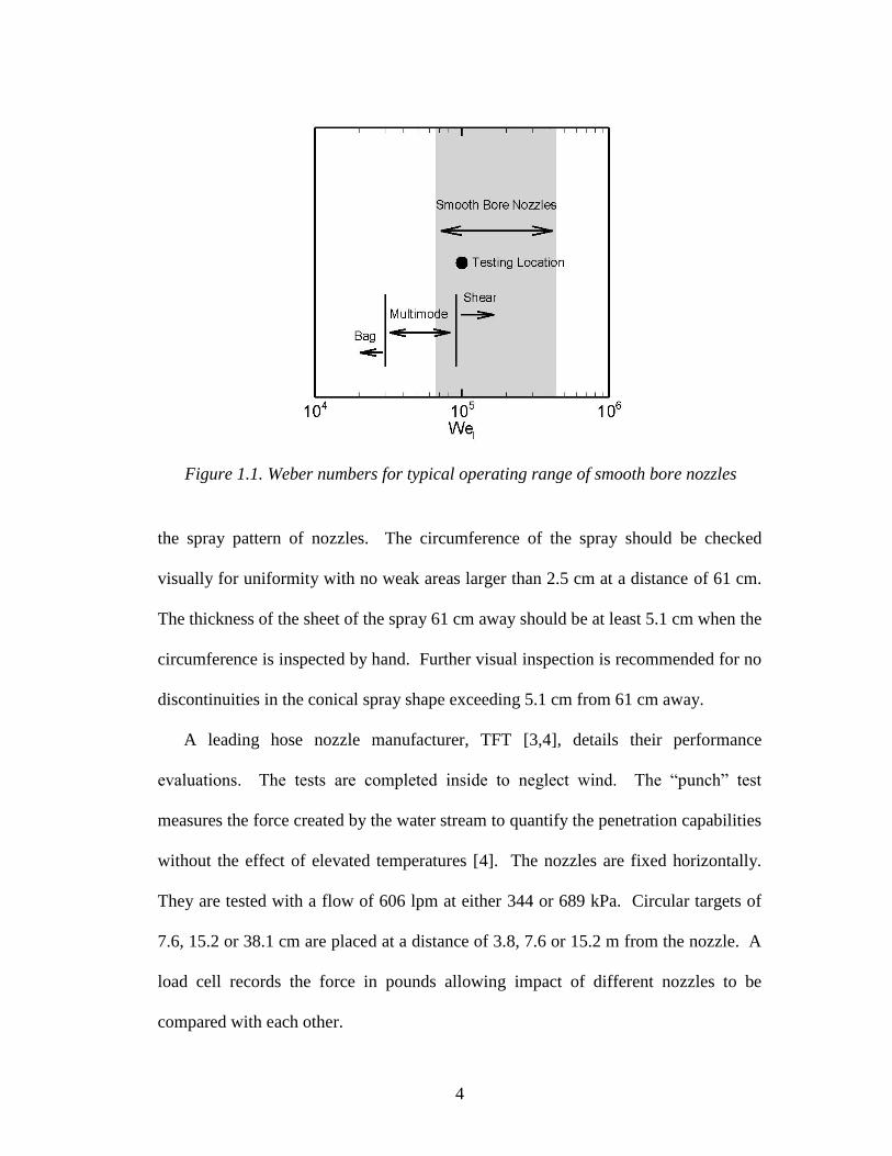
uncommonly low or high flows. The typical operating range was defined based on
the total number of nozzles operating at a given Weber number condition and shown
in Fig. 1.1. The range is defined at the Weber number corresponding to 12.5% and
87.5% of the total operating conditions of the nozzles. The testing condition and
regions denoting breakup regimes in Fig. 1.1 will be discussed later.
Hose stream nozzle standards are given in NFPA 1964: Standard for Spray
Nozzles [7]. The rated flow and pressure determined by the manufacturer must be
used for the NFPA 1964 performance evaluations. In section 4.2.2. of the NFPA
standard, the straight stream jets must contain 90% of their discharge at a distance 3
m from the nozzle in a 30.5 cm diameter circle if the nozzle rated discharge is lower
than 1325 lpm or in a 38.1 cm diameter circle if the nozzle rated discharge is greater
than 1325 lpm. In section A.4.2.3., NFPA recommends rudimentary inspections for
4
the spray pattern of nozzles. The circumference of the spray should be checked
visually for uniformity with no weak areas larger than 2.5 cm at a distance of 61 cm.
The thickness of the sheet of the spray 61 cm away should be at least 5.1 cm when the
circumference is inspected by hand. Further visual inspection is recommended for no
discontinuities in the conical spray shape exceeding 5.1 cm from 61 cm away.
A leading hose nozzle manufacturer, TFT [3,4], details their performance
evaluations. The tests are completed inside to neglect wind. The “punch” test
measures the force created by the water stream to quantify the penetration capabilities
without the effect of elevated temperatures [4]. The nozzles are fixed horizontally.
They are tested with a flow of 606 lpm at either 344 or 689 kPa. Circular targets of
7.6, 15.2 or 38.1 cm are placed at a distance of 3.8, 7.6 or 15.2 m from the nozzle. A
load cell records the force in pounds allowing impact of different nozzles to be
compared with each other.
Figure 1.1. Weber numbers for typical operating range of smooth bore nozzles
5
Another TFT test is for the stream trajectory [3]. The hose is fastened to the floor
and then angled 30° upward. The stream location is measured using a laser-operated
transit. Trajectory plots are provided by TFT for different flows of each hose nozzle.
To account for varying discharge angles, TFT provides a supplemental plot to alter
the trajectory both horizontally and vertically with the use of height and reach factors.
TFT published a report on different attack procedures [8]. The purpose of the
report is to describe the attack approach to maximize the amount of water used. TFT
calculates the amount of water needed to absorb enough heat for extinguishment,
assuming that 90% of the water is used effectively for heat removal. This calculation
assumes that the fire is extinguished by absorbing all of the heat in the volume.
Different approaches for hose streams include direct attack for smaller fires, applying
the hose stream to the ceiling for blocked fires, or wetting necessary areas to walk
through escape. TFT recommends that the stream be applied in a clockwise direction
to drive hot gases away from the nozzle based on trial and error. TFT explains that a
stationary stream is ineffective because it allows a convection current from the fire to
set up around the spray.
1.2.2. Hose Stream Research
Rasbash [9] measured the amount of water needed to extinguish fires with
furnished volumes from 0.13 – 56.6 m3. Smaller tests were completed in model
rooms at temperatures of 700 – 900° C. Extinguishment for smaller tests came from
two 0.79 cm water jets from 34.5 – 827 kPa. Small-scale tests show only 3.78 liters
were needed per 28.3 m3. A fire brigade carried out full-scale tests at 151 lpm and
690 kPa. Full-scale tests range from 30.3 – 37.9 liters per 28.3 m3 to extinguish a
6
fire. The critical amount of water was determined when little excess water was left
on the floor after testing. Rasbash later reviewed 5 full-scale extinction tests from
other hose stream researchers [10]. For each test a critical water rate was found
defined as the minimum rate needed to extinguish a post-flashover fire. The critical
water rates ranged from 5.6 – 7.4 g/m2s. Rasbash analyzed tests carried out in the US
and UK that measures the actual amount of water used by fire fighters for fire from 5-
60000 m2
in floor area. Rasbash concluded that the amount of water used in actual
fire fighting is about 10-20 times greater than what is needed. A reason given for the
discrepancy is the flow rate in real world applications is ten times that of the
experiments and leads to an excess of water. More time is needed to extinguish a fire
if the critical water rate is used and for fire fighting purposes time is of great
importance.
Milke [11] conducted full-scale experiments to simulate hose streams in fires.
For 5 tests, water jets were injected into a 22 m3 room after the fire reached flashover.
The nozzle dimensions are not provided but the nozzles were designed to produce a
swirling liquid jet with a spray cone of 60°. Droplet measurements were taken 1.52
m from the nozzle along the stream at the lateral edge of the spray cone with a strobe
and camera setup. Volume median droplet sizes ranged from 0.48 – 0.63 mm.
Grant [12] provided a comprehensive review of water sprays for fire suppression.
Grant discussed in detail the droplet evaporation and heat transfer for elevated
temperatures. Droplet penetration into a fire is evaluated to determine the reduction
of drop size and velocity. When the droplet reaches a surface different interactions of
wetting the area are observed depending on the drop size, temperature and velocity.
7
Grant [12] provided a qualitative discussion regarding fire hose streams spray
behavior. The approach of fire hoses is to remove heat from the fuel along with
wetting the surrounding area. The primary goal is usually to have the water reach the
base of the fire. Water vapor filling the area is a secondary benefit that is not relied
on for extinction. Grant addressed the basics of hose stream spray characteristics.
The solid jet flow evolves from a cylindrical column to droplets because of internal
turbulence and velocity difference with the still air. The subsequent droplets form a
polydispersed spray. This suppression goal is in contrast to the manufacturer TFT
[8]. The critical water amount estimated by TFT is an aggressive approach of heat
removal. TFT assumes the fire’s heat is removed by water while Grant’s approach of
wetting the fire area leads to excess water. Grant supported Rasbash’s [10] claim that
real world fire fighting applications use a significant amount of excess water.
Rasbash stated 10 – 20 times the critical water amount is used while Grant believed
the number to be 10 – 100.
1.2.3. Atomization of Liquid Jets in Still Gases
Studies have provided background for different column breakup regimes
according to Weber number ranges. Birouk and Lekic [13] and Dumouchel [14]
classify the atomization regime of liquid jets in ambient air as any liquid jet with Wel
> 33200. The jets are at a high velocity and begin to disintegrate along the liquid
core. The disintegration is a stripping behavior where droplets were significantly
smaller than the nozzle diameter.
A similar Weber number is found again by Sallam [15] to describe jet column
breakup regimes. Scenarios included round water jets injected downward with fully
8
developed turbulent flow. Weber numbers ranged from 235 – 270000. The
experiments involved shadowgraphy from double-pulsed YAG lasers, a procedure
discussed further in Section 2.2. When Weber numbers exceeded 30000 the jets were
shown to be in bag/shear, also referred to as multimode, breakup mode. At this point
the liquid core was distorted by the turbulence causing the parts of the column to be
in gaseous crossflow due to the velocity difference with the still air. The distortion
produces bag-like structures to break off of the liquid core. As the Weber number
increases the droplets are produced from shearing off of the liquid column. No
specific Weber number is found from Sallam for the transition. The behavior was
similar to nonturbulent jets in gaseous crossflow. Weber number ranges for
nonturbulent jets in crossflow have the multimode breakup regime to take place from
Weber numbers of 24900 – 91400 and shear breakup regime occurring when Weber
numbers are greater than 91400 [16]. From Fig. 1.1 it is seen that typical smooth
bore hose nozzles are expected to be in the shear breakup regime.
Sallam [15] expands on a previous correlation for the liquid core based on the
Weber number. The liquid core of the jet is considered intact until the core is of
comparable size to the drops formed. Wu and Faeth [17] developed the correlation to
determine the length of the liquid core in the streamwise direction:
𝐿𝑐𝐷= 7.40𝑊𝑒𝑙
0.34 (1.2)
This correlation was extended by Sallam to incorporate more cases and provide Lc/D
equations for different Weber number ranges [15]. When Weber numbers exceed
30000 the liquid core correlation becomes independent of Weber number. The
9
increased flow is balanced out by increased disintegration. The modified correlation
becomes:
𝐿𝑐𝐷= 11.0
𝜌𝑙𝜌𝑔
1/2
(1.3)
Droplet ranges for typical fire fighting applications as reviewed by Grant [12] are
typically between 0.1 mm (fixed nozzles) to 1 mm (sprinklers). However, for hose
streams the range is usually from 0.5 mm to 1.5 mm. Yoon [18] conducted extensive
research on droplet and velocity distributions for fire suppression purposes. Jets in
the shear breakup regime are injected horizontally through a conical nozzle creating a
widely dispersed mist spray. Yoon used a Phase Doppler Particle Analyzer to obtain
measurements based on laser-induced light scattering.
Wu and Faeth [17] created a correlation for the onset of primary drop breakup
along the liquid core based on the Weber number and nozzle diameter. The onset of
primary breakup is determined by the location where droplets are first seen.
𝐿𝑏𝐷= 2000𝑊𝑒𝑙
−0.67 (1.4)
Experimental measurements ranged from Wel of 100 – 1100000. As the Weber
number increases, the onset location for primary breakup gets closer to the nozzle.
Sallam [19] studied the drop size of high Weber number jets with respect to the
streamwise direction, x. The drop sizes from Sallam are determined by the size of the
tip from ligaments completing Rayleigh breakup protruding from the core. The
Sauter Mean Diameter, d32, is a characteristic drop size where the diameter has the
same volume to surface area ratio.
10
2/1
2/1
32 27.0
lDWe
x
D
d (1.5)
The correlation shows that the drop size increases along the streamwise direction
because of larger jet disruptions. The drop size decreases as the Weber number
increases.
1.3. Research Objectives
The research is conducted to develop a process for how to test and analyze the
spray characteristics of hose streams. The experiments involve a water jet in the
shear breakup regime. The results can be applied to smooth bore hose nozzles of
varying diameters. The goal is to quantify the dispersion, flow, drop size and velocity
at the midpoint between the nozzle and the end of the liquid core.
11
2. Experimental Setup and Procedure
2.1 Nozzle Setup and Test Conditions
The piping is connected to a rigid member perpendicular to the ceiling. The
connection allows for the nozzle setup to be moved in the vertical direction. The
nozzle is mounted on a plate that has an option of pivoting to test for the flow at
different angles. Water is delivered through a smooth cylindrical acrylic tube. The
acrylic tube, referred to as the nozzle, has an inner diameter of 1.27 cm. Fully
developed turbulent flow is found in fire hoses due to the high velocities and long
lengths. To reach fully developed turbulent flow, testing conditions require the L/D
to be at least 36 based on a correlation with the Reynolds number [20]. Similar
testing uses L/D > 40 as a standard for fully developed turbulent flow [15,17,19].
The nozzle used is 61 cm long and has an L/D of 48. The pressure is recorded before
entering the nozzle with a Pitot tube connected to an electronic pressure transducer.
Pressure loss calculations from the connection to the piping and through the nozzle
are used to determine the nozzle exit stagnation pressure of 300 kPa [20]. The
average jet exit velocity, consistent with the flow rate and the pressure reading, is 24
m/s.
Testing was conducted under ambient conditions. The densities of water and air
were 998 kg/m3 and 1.2 kg/m
3. The viscosities of water and air were 1.003 x 10
-3
kg/ms and 1.8 x 10⁻⁵
kg/ms. Surface tension of water was taken to be 0.0728 N/m.
12
The water jet is injected into still air at a 180 lpm. The flow contains no
cavitation. The Weber number of 100000 places the jet in the shear breakup regime,
as shown in Fig. 1.1. This Weber number would be comparable to a fire fighting
hose nozzle with an inner diameter of 2.9 cm and a flow of 170 lpm. Fig. 2.1 displays
the axis orientation for the test setup. The three axes are defined as the streamwise
direction x, the vertical cross-stream direction z, and the horizontal cross-stream
direction y. The center of the nozzle exit is set as the origin for all measurement.
From Eq. (1.2) the liquid core is estimated to end at Lc/D = 317, or 4.0 m. Tests
are conducted to include the mid point between the nozzle exit and the theoretical end
of the liquid core as seen in Fig. 2.2.
Figure 2.1. Axis orientation
Figure 2.2. Mid point of liquid core

13
For the patternator test, the water is collected at x/D of 158, or 2.0 m. The
shadowgraphy measurements are taken along a 12 cm section in the streamwise
direction. Therefore the testing area includes x/D from 150 to 160. The test
conditions are displayed in Table 1.
Table 1: Test Conditions
Diameter (cm) Flow (lpm) Wel Pressure (kPa) x/D
1.27 180 100000 300 150 - 160
2.2 Diagnostics
Drop size and velocity are measured using shadowgraphy techniques with a
LaVision system. The apparatus is placed along the streamwise direction to capture
images between 190 - 202 cm as seen in Fig. 2.3. The spray goes through an opening
section in the middle of the test setup. Water barriers protect the laser, camera and
computer system. A double-pulsed YAG laser is connected with fiber optics to a
diffuser. The light output from the diffuser is expanded with a 20 cm Fresnel lens
placed 15 cm away from the core of the spray along the horizontal cross-stream
direction shown in Fig. 2.3 (a). An Image ProX M4 CCD camera with a 60 mm lens
faces the diffuser at a distance of 70 cm from the jet along the horizontal cross-stream
direction. Laser pulses are emitted in pairs separated by 80 s. The camera is
synchronized to capture particles in the image plane for each laser pulse. A quick
laser pulse of 3 - 5 ns allows the images to hold particles as if they are frozen. The
diffused light against the Fresnel lens serves as a backlight. The camera records the
change in illumination from the water in front of the lit background. An edge
detection algorithm in the LaVision SizingMaster program distinguishes droplets and
14
their size with the light intensity difference. A Particle Tracking Velocimetry
algorithm then tracks similar particles in the paired images inside of an interrogation
window set by the user. Non-spherical particles are not included. The velocity of
each droplet is calculated based on the distance divided by the time (80 s) between
the paired images. The depth of field for the image area is measured to be 2.8 cm.
Measurements begin after steady flow is established. Measurements are taken in
3 locations along the vertical cross-stream direction to include the majority of the
vertical spray width. 200 image pairs are taken for each of the 3 locations. The
results are overlapped and combined to show the spray width without breaks between
testing locations. Droplets from only one location are included in overlapping areas
to prevent over counting. The total amount of droplets used in analyses is about
175000.
The flows from the shadowgraphy measurements are calculated in increments of
the nozzle diameter along the vertical cross-stream direction. The flows are evaluated
for each drop and summed for each D. The core and non-spherical drops are not
included in the droplet flow calculation. The total droplet flow is derived from:
(a) (b)
Figure 2.3. Shadowgraphy test setup (a) front view (b) side view
15
udAQ Ts )(
(2.1)
The velocity used is the streamwise velocity for the flow to be given as the
streamwise flow. Cylindrical coordinates are used to derive the droplet flow. This
assumes the flow is circular in shape and can be rotated about the center.
V
VdrdruQ d
ddTs )( (2.2)
The equation is revolved about the streamwise axis. The flow is integrated with
separate rotations above the core and below the core. The ratio of the volume from
the drops to the total tested volume is used to account for the fact that the entire
volume is not filled with water. The equation includes π because flow is calculated in
the entire vertical cross-stream direction.
(Qs)T
NYdofXudrdVd
(2.3)
The flow is divided by the number of images, N. Weighting the drops with r (the
distance from the core) is necessary to account for the change in area tested. When
close to the core only a small amount of the spray is included in the depth of field.
Further from the core a higher amount of the spray is in the depth of field.
The characteristic drop size, dv50, is defined by the median diameter according to
the volume distribution. The distance to the core and the streamwise velocity weights
the volume fraction. The distance from the core, r, is needed as it was for the flow
calculations to account for the change in area. Shadowgraphy measurements have a
bias towards slower drops since their slow velocity makes it more likely to “freeze”
them in the testing area. The bias is corrected by weighting the velocity in the
volume fraction equation. The volume fraction is then:
16
ddd
ddd
Vru
VruVF (2.4)
2.3 Patternator Test
Collecting water with a grid of tubes perpendicular to the jet creates a patternator.
Water is collected in solid smooth acrylic tubes with inner diameters of 0.95 cm.
They are spaced 4.6 cm apart in a wire mesh as seen in Fig. 2.4. The simplified grid
displayed in Fig. 2.5 limits points to measure one side of the spray in the horizontal
cross-stream direction. Symmetry in the horizontal cross-stream direction allows for
the entire spray to be accounted for. One column extends past the core to verify for
the flow being centered. The grid has the ability to be used for different conditions
and therefore water is only collected from the tubes with measureable flow.
Figure 2.4. Grid separation
17
The side view of the patternator test setup is shown in Fig. 2.6. The acrylic tubes
extend 3 cm out from the grid to reduce the effect of water splashing back into the
spray and entering the tubes. The tubes are 35 cm in length and connected to a
second wire mesh on the other side. The length helps to reduce the splashing effect
by distancing the water collection from obstructions. They are angled 1° downward
along the streamwise direction for water to continue to flow without a significant
effect on the water collection. Larger soft tubing is connected to the back of each
acrylic tube. The soft tubing is angled downward through a water barrier where it is
collected in a container.
During testing, the water flows until a steady state is reached inside the tubing.
Each tube is measured individually. A portion of the outside of the soft tubing is
Figure 2.5. Patternator test setup facing jet
Water
Barrier
Container
Collection
Tubes

18
surrounded by cloth to prevent water from running on the outside of the tubing to be
collected. The water flows from one tube into a container while the time is recorded.
For each point the water volume with time is measured with a beaker and a
stopwatch. The measurements are fluxes due to the collection area of the tubes. The
grid is shifted horizontally 2.3 cm and the nozzle is raised vertically 2.3 cm to allow
for more data points.
The flow flux, Qp”, is the recorded flux from each tube. The flow flux is
normalized by:
𝑄𝑝"
𝑛= 𝑄𝑝𝑚 𝐴𝑝
(2.5)
In Eq. (2.5) Qpm is the flow measured in each tube. This creates a fraction where the
average Qp”/(Qp”)n will be 1. This flow is the spray flow and does not include the
core. This is similar to the shadowgraphy results that only include spherical droplets,
Figure 2.6. Patternator test setup side view
19
therefore not using the core flow. The length of the core is estimated from
shadowgraphy images. The patternator measurements include half of the spray with
respect to the horizontal cross-stream direction and are mirrored to create a full
picture.
The measurement increments are coarser than shadowgraphy since the patternator
tubes are spaced every 1.8D. The flow along the centerline is rotated cylindrically
producing the equation for flow for each location:
𝑄𝑝 = 𝑄𝑝"𝜋𝑟∆𝑟 (2.6)
The distance between tubes is used as Δr. The total flow, (Qp)T, is the summation of
the calculated flows from the tubes not including the core.
20
3. Results and Analysis
3.1 Spray Dispersion
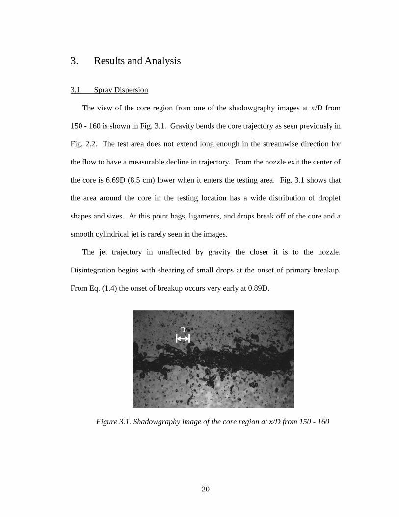
The view of the core region from one of the shadowgraphy images at x/D from
150 - 160 is shown in Fig. 3.1. Gravity bends the core trajectory as seen previously in
Fig. 2.2. The test area does not extend long enough in the streamwise direction for
the flow to have a measurable decline in trajectory. From the nozzle exit the center of
the core is 6.69D (8.5 cm) lower when it enters the testing area. Fig. 3.1 shows that
the area around the core in the testing location has a wide distribution of droplet
shapes and sizes. At this point bags, ligaments, and drops break off of the core and a
smooth cylindrical jet is rarely seen in the images.
The jet trajectory in unaffected by gravity the closer it is to the nozzle.
Disintegration begins with shearing of small drops at the onset of primary breakup.
From Eq. (1.4) the onset of breakup occurs very early at 0.89D.
Figure 3.1. Shadowgraphy image of the core region at x/D from 150 - 160
21
The breakup occurs close to the nozzle because it has a high Weber number. The
column breakup immediately following the nozzle exit involves solely small droplets
shearing off of the jet. The core trajectory and diameter decline along the streamwise
direction. The amount of core disruption is shown to increase as seen in Fig. 3.1
when compared to the jet at the nozzle exit. Primary breakup in the testing location
causes large amounts of the core to be stripped off creating ligaments or drops. The
jet diameter for the testing area is estimated to have decreased 15% from the original
diameter based on measurements in images where the core remained cylindrical. The
flow in the core has decreased to 72% of the initial nozzle exit flow. Most of the flow
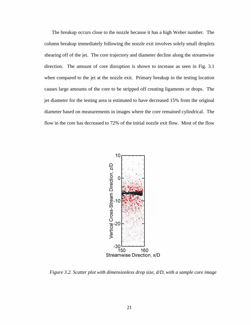
Figure 3.2. Scatter plot with dimensionless drop size, d/D, with a sample core image
22
has been kept in the core when it arrives at the testing location. The testing location is
placed so that it is at the mid point of the liquid core length. A decrease in diameter
of 15% at the mid-point of the liquid core length shows that the core diameter does
not decrease with linearly. The diameter decline begins minimal at the nozzle and
increases along the streamwise direction.
Fig. 3.2 displays the dimensionless droplet sizes in the entire recorded spray
width with a sample image imposed on the data. The vertical spray width is defined
as the measurable droplet area in the vertical cross-stream direction. The core area
does have a small amount of drops due to fluctuations. The spray width extends
slightly below the tested area, but later calculations show the flow has significantly
decreased by this point.
A clear difference can be seen between the spray near the core and the spray with
smaller drops of the outer area. Many droplets around the core will produce
secondary breakup into smaller drops due to their large size and velocity. A drop
with a drop Weber number above 12 causes droplet bag breakup where the droplet
ruptures and produces many smaller drops [21]. Secondary breakup occurs for 3910
drops, or 2.2%. The area outside of the core includes small droplets that are the
result of secondary breakup or droplets that sheared off the jet closer to the nozzle.
The main purpose of the patternator is to define the shape of the spray. Fig. 3.3
uses the patternator test results to create a contour plot comparing the spray flow flux
fraction, Q”p/(Q”p)n. The core length is estimated to be about 5D from Fig. 3.1 and
not included for the spray flow from the patternator. The core length is large because
of deformations. Generally a circular shape is seen. The circular shape is stronger

23
closest to the core and becomes more elliptical farther from the core. The bottom
portion of the spray extends slightly further because of the effect of gravity. The
spray is wider below the core because gravity helps initiate the breakup. The spray
directly surrounding the core has significantly greater flow than the remaining area.
The spray area appears smaller with the patternator than from the shadowgraphy
results. This could be due to limits in water collection through the tubing.
3.2 Flow
Fig. 3.4 shows the flow fraction from the droplets along the vertical cross-stream
direction from shadowgraphy results. The flow is for droplets only and does not
include the core or nonspherical drops. The core is shown 6.69D below the initial
Figure 3.3. Contour plot from patternator results of the measured flow flux
fraction from spray tubes

24
nozzle location. It is seen that the core region contains little drop flow since the
fluctuations have a length of approximately 5D, as discussed previously. The droplet
flow peaks outside of the core region. Testing restrictions limited the measurements
to approach a flow fraction of 0.0006 at the top of the spray and 0.0036 at the bottom.
The outlying flow is considered negligible for the calculations.
Distinct differences in droplet size, amount and velocity are seen in the high-flow
region surrounding the core. A high flow region is labeled in Fig. 3.4. The region is
defined with a cutoff value where different flow behavior is seen. The high flow
region includes the middle area of the spray width when Qs/(Qs)T is above 0.02. The
low flow region includes the flow area above and below the high flow area. The high
Figure 3.4. Flow fraction from shadowgraphy droplets along the vertical cross-
stream direction in increments of D, cumulative flow fraction shown as a curve
with the origin in the center of the core
25
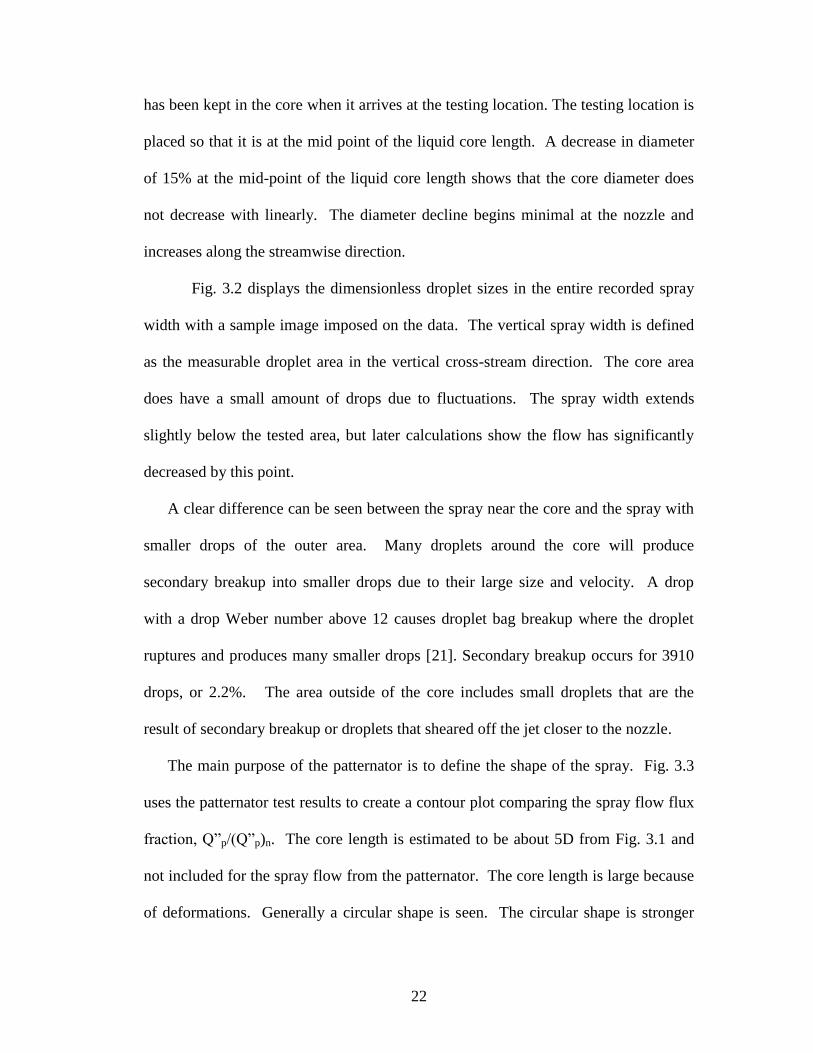
flow region is 13D in length and contains 84% of the droplet flow. For a hose stream
the high flow region is important to enable a long trajectory and deep penetration to
the fire. The cumulative flow fraction expands out from the center of the core flow.
A similar trend of flow fraction and cumulative flow fraction occurs above and below
the core but with a different scale. Below the core has greater flow that extends
farther out from the core. The bottom flow accounts for 75% of the total droplet flow
while the top contains 25%.
The total droplet flow is 9% of the initial flow at the nozzle exit. The core flow is
72% of the initial flow as previously discussed. The ligaments and bags breaking off
of the core mostly account for the remaining 19%. The flow from the bags and
Figure 3.5. Flow fraction of spray from patternator along the vertical cross-stream
direction in increments of 1.8D, cumulative flow fraction shown as a line with the
origin in the center of the core

26
ligaments are not calculated but from Fig. 3.1 they can be seen to be a significant
amount of the flow in the testing area. Minor amounts of flow are also lost in the
small drops that shear off around the nozzle after the onset of primary breakup.
These droplets would not be seen at x/D of 150.
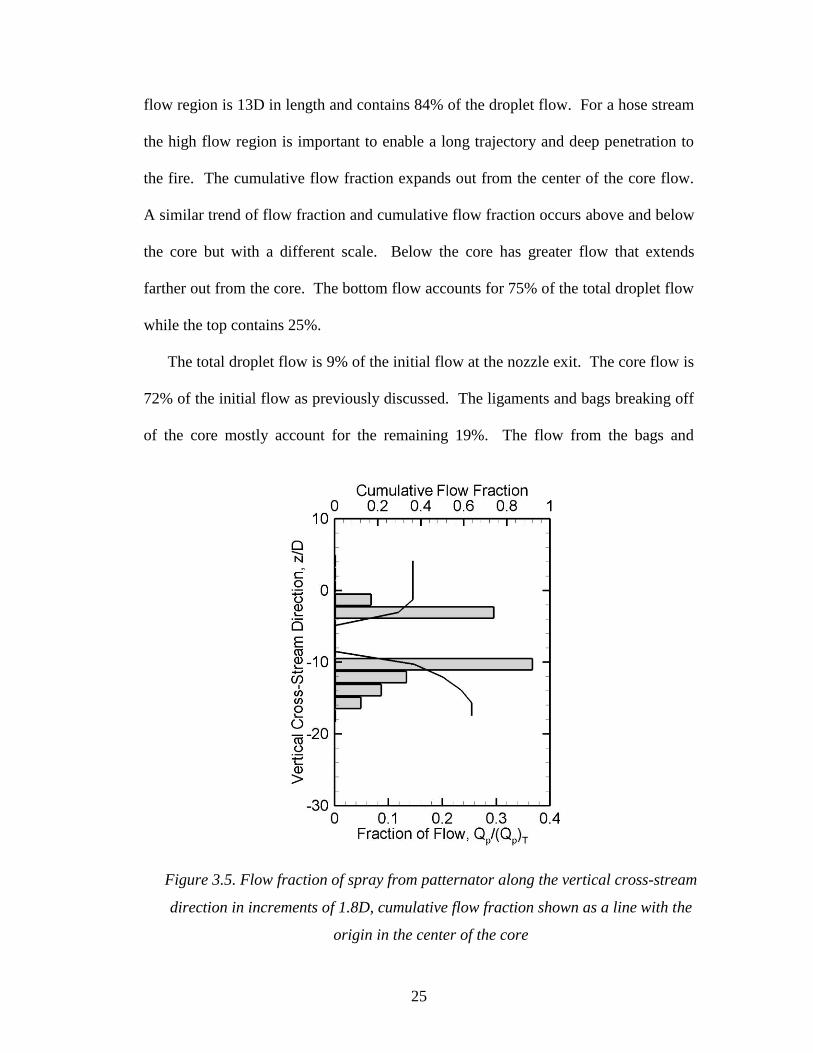
Flow measurements from the spray of the patternator test are shown in Fig. 3.5.
The measurement region is smaller than in Fig. 3.4. The results take place mostly in
the high flow region. The spray flow is distributed 36% above the core and 64%
below the core. The core flow is not included in the total flow. When the core flow
is compared to the flow from the spray, the spray accounts for 11% of the flow and
the core accounts for the remaining 89%. The patternator flow shows slight
discrepancies with the shadowgraphy results. This is possibly a result of the coarse
grid, water collection method, or the inability to differentiate spherical droplets.
3.3 Characteristic Drop Size
The primary suppression goal of hose streams is to penetrate the base of the fire
as explained by Grant [12]. Therefore the characteristic drop size important for hose
streams is the volume median drop size, dv50. The histogram for drop size distribution
is shown in Fig. 3.6. The dv50 for the spray is 1.7 mm or d/D = 0.13. A peak is seen
at d/D of 0.1 but a normal distribution is not found. The histogram shows there are
more small drops with the distribution stretched to include the larger drops. The drop
size distribution above the core is identical to the distribution below the core and can
be attributed to the large droplets surrounding the core dominating the volume
fraction.

27
Figure 3.6. Drop size distribution according to droplet volume fraction with line
showing the cumulative volume fraction
The high-flow range accounts for 89% of the volume fraction and therefore
dominates the distribution in Fig. 3.6. The drop size distribution of the low flow
region is shown in Fig. 3.7. A different distribution is seen with the peak around d/D
of 0.05. The dv50 for the low flow region is 0.98 mm or d/D = 0.077. The low flow
region shows smaller droplets in a more narrow range.
Surface area is important for fire suppression because of heat extraction, a
secondary benefit from hose streams. The equation of d32 is weighted as discussed
earlier for dv50 to become:
d32 udrdd
3udrdd
3 (3.1)
28
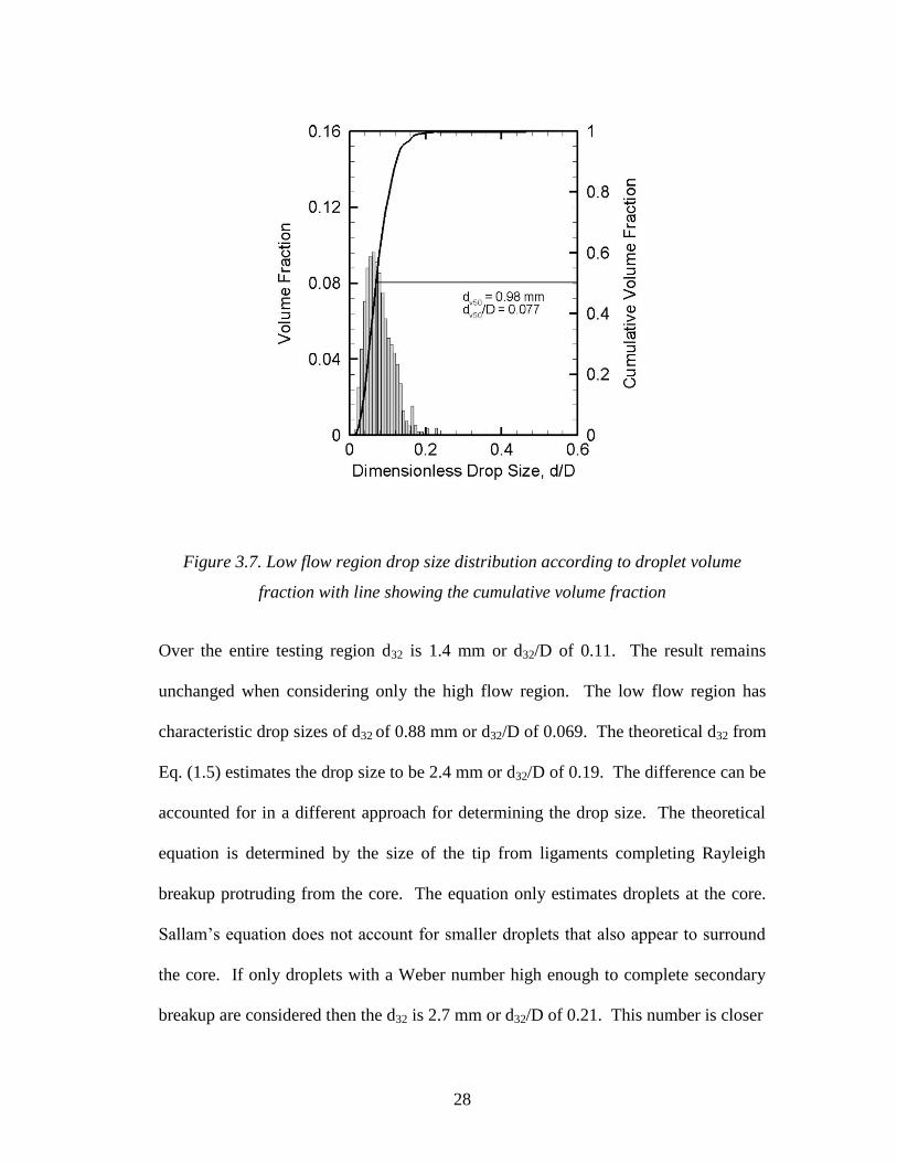
Figure 3.7. Low flow region drop size distribution according to droplet volume
fraction with line showing the cumulative volume fraction
Over the entire testing region d32 is 1.4 mm or d32/D of 0.11. The result remains
unchanged when considering only the high flow region. The low flow region has
characteristic drop sizes of d32 of 0.88 mm or d32/D of 0.069. The theoretical d32 from
Eq. (1.5) estimates the drop size to be 2.4 mm or d32/D of 0.19. The difference can be
accounted for in a different approach for determining the drop size. The theoretical
equation is determined by the size of the tip from ligaments completing Rayleigh
breakup protruding from the core. The equation only estimates droplets at the core.
Sallam’s equation does not account for smaller droplets that also appear to surround
the core. If only droplets with a Weber number high enough to complete secondary
breakup are considered then the d32 is 2.7 mm or d32/D of 0.21. This number is closer
29
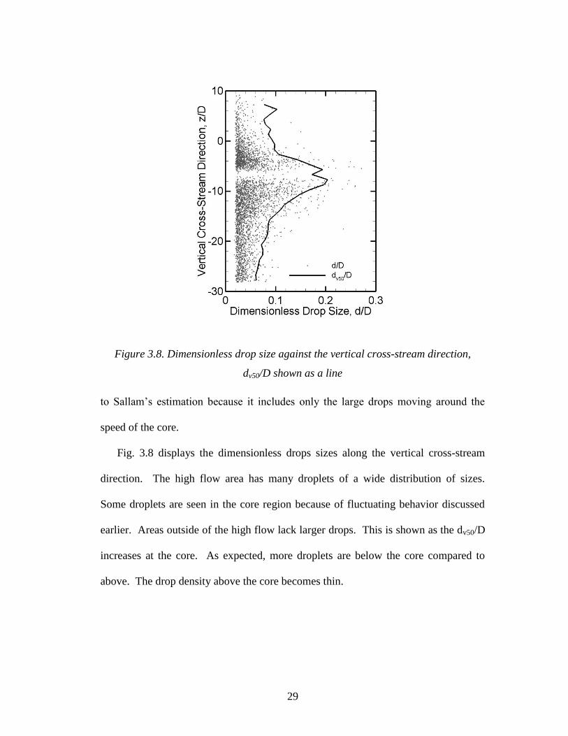
Figure 3.8. Dimensionless drop size against the vertical cross-stream direction,
dv50/D shown as a line
to Sallam’s estimation because it includes only the large drops moving around the
speed of the core.
Fig. 3.8 displays the dimensionless drops sizes along the vertical cross-stream
direction. The high flow area has many droplets of a wide distribution of sizes.
Some droplets are seen in the core region because of fluctuating behavior discussed
earlier. Areas outside of the high flow lack larger drops. This is shown as the dv50/D
increases at the core. As expected, more droplets are below the core compared to
above. The drop density above the core becomes thin.
30
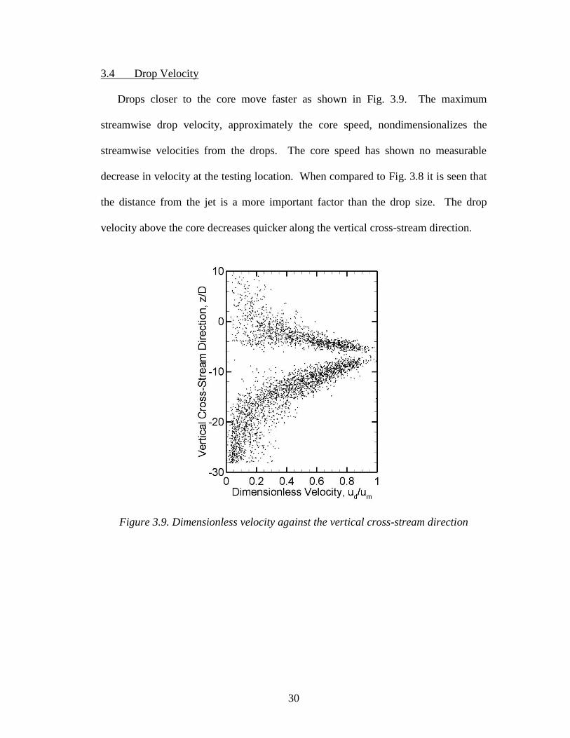
3.4 Drop Velocity
Drops closer to the core move faster as shown in Fig. 3.9. The maximum
streamwise drop velocity, approximately the core speed, nondimensionalizes the
streamwise velocities from the drops. The core speed has shown no measurable
decrease in velocity at the testing location. When compared to Fig. 3.8 it is seen that
the distance from the jet is a more important factor than the drop size. The drop
velocity above the core decreases quicker along the vertical cross-stream direction.
Figure 3.9. Dimensionless velocity against the vertical cross-stream direction
31
4. Conclusion
Experiments quantified the spray characteristics of a round jet in the shear
breakup regime oriented parallel to the floor. The spray is examined halfway
between the nozzle and the theoretical end of the liquid core. Testing included a
patternator and shadowgraphs. The patternator collected water along the streamwise
direction with a grid of 0.95 cm tubes. The patternator established the shape of the
spray. Shadowgraphy obtained images over the spray width. Drop size, flow,
velocity and spray distribution were found from the images. The major conclusions
are:
1) The droplet spray inside the shadowgraphy testing area contains 9% of the
initial nozzle exit flow. Core flow accounts for 72%. Most of the
remaining flow is attributed to ligaments or non-spherical drops. The high
flow region surrounding the core contains 84% of the droplet flow.
2) The dv50/D and d32/D of the droplet spray are 0.13 and 0.11. The drop
distribution favors smaller drops. The dv50/D and d32/D of the low flow
region are 0.077 and 0.069.
3) The spray behavior below the core contains more drops over a wider range
than above the core. The flow from drops was distributed 75% below the
core and 25% above the core. The spray from patternator and
shadowgraphy is an elliptical shape.
The high flow region is of most importance for hose streams. Smooth bore
nozzles rely on the core staying intact to deliver large amounts of water to the fire

32
through a solid jet. The approach will lead to excess water but the water can be
limited when there are less droplets outside of the core region.
The experiments developed a test setup, conditions and process to allow for
further exploration of the research. More is needed to fully understand the spray.
Testing the entire liquid core will confirm the length and allow the core disintegration
to be correlated along the streamwise direction. Different flows and diameters can be
used to see how the characteristics scale for other scenarios. Hose streams are
typically oriented at an angle. Further tests can determine the effect of the nozzle
angle on the spray.
33
Bibliography
[1] Stroup, D., “Hose Stream Characterization and Effectiveness Modeling”,
National Institute of Standards and Technology, Gaithersburg, MD, 2007.
[2] Sutton, P., Jan van der Heyden (1637 – 1712), Yale University Press, 2006.
[3] Task Force Tips, Inc., “Range and Trajectory Data of Hand Held Nozzles”,
1994.
[4] Task Force Tips, Inc., “The Comparison of Various Types of Nozzles
Operating at Specific Flows and Pressures and their Effect on the Impact or
Punch of Fire Streams”, 2001.
[5] Akron Brass Co., “All Nozzles Catalog”, 2009.
[6] Elkhart Brass Manufacturing Company, “Catalog F”.
[7] NFPA 1964: Standard for Spray Nozzles, 2008.
[8] Oster, G., Wiseman, J., “Balanced Fire Attack”, Task Force Tips.
[9] Nash, P., Rasbash, D., “The Use of Water in Fire-Fighting”, Fire Research
Station, Boreham, England, 1955.
[10] Rasbash, D., “The Extinction of Fire with Plain Water: A Review”, Fire
Safety Science-Proceedings of the First International Symposium, pp. 1145-
1163, 1986.
[11] Milke, J., Evans, D., Hayes Jr., W., “Water Spray Suppression of Fully-
Developed Wood Crib Fires in a Compartment”, NBSIR 88 3745, National
Bureau of Standards, 1988.
34
[12] Grant, G., Brenton, J., Drysdale, D., “Fire Suppression by Water Sprays”,
Progress in Energy and Combustion Science, Vol. 26, pp. 79-130, 2000.
[13] Birouk, M., Lekic, N., “Liquid Jet Breakup in Quiescent Atmosphere: A
Review”, Atomization and Sprays, Vol. 19, pp. 501-528, 2009.
[14] Dumouchel, C., “On the Experimental Investigation on Primary Atomization
of Liquid Streams”, Experiments in Fluids, Vol. 45, pp. 371-422, 2008.
[15] Sallam, K., Dai, Z., Faeth, G., “Liquid Breakup at the Surface of Turbulent
Round Liquid Jets in Still Gases”, International Journal of Multiphase Flow,
Vol. 28, pp. 427-449, 2002.
[16] Ng, C., Sankarakrisham, R., Sallam, K., “Bag Breakup of Nonturbulent
Liquid Jets in Crossflow”, International Journal of Multiphase Flow, Vol. 31,
pp. 241-259, 2008.
[17] Wu, P., Faeth, G., “Onset and End of Drop Formation Along the Surface of
Turbulent Liquid Jets in Still Gases”, Physic of Fluids, Vol. 7, pp. 2915-2917,
1995.
[18] Yoon, S., Kim, H., Hewson, J., “Effect of Initial Conditions of Modeled PDFs
on Droplet Characteristics for Coalescing and Evaporating Turbulent Water
Spray Used in Fire Suppression Applications”, Fire Safety Journal, Vol. 42,
pp. 393-406, 2007.
[19] Sallam, K., Dai, Z., Faeth, G., “Drop Formation at the Surface of the Plane
Turbulent Liquid Jets in Still Gases”, International Journal of Multiphase
Flow, Vol. 25, pp. 1161-1180, 1999.
[20] White, F., Fluid Mechanics, Sixth Edition, Mc-Graw Hill, 2008.

35
[21] Pilch, M., Erdman, C., “Use of Breakup Time Data and Velocity History Data
to Predict the Maximum Size of Stable Fragments for Acceleration-Induced
Breakup of a Liquid Drop”, International Journal of Multiphase Flow, Vol.
13, pp. 741-757, 1987.