abstract thesis: a graph transformation method for …
TRANSCRIPT

ABSTRACT
Title of Thesis: A GRAPH TRANSFORMATION METHOD
FOR ROBOTIC SATELLITE SERVICING DOWN-SELECTION
Jessica Rae Lieberman Knizhnik, Master of
Science, 2017 Thesis Directed By: Associate Professor, Mark Austin, Department
of Civil and Environmental Engineering and Institute for Systems Research, University of Maryland
As remote robotic space satellite servicing technologies develop, each servicer satellite
will need to account for a number of servicing scenarios and consider a variety of
alternate design solutions to best meet the most servicing scenario requirements. This
thesis presents a graph transformation method for systematically down-selecting the
number of design options available, and highlighting trade-offs in sets of design
solutions which best meet satellite servicing task requirements while also reducing total
mass, maximum power needed and servicing time. The proposed method successfully
identifies for further consideration several best design solutions from a set of
approximately 10,000 potential solutions in the first test case examined, and from a set
of approximately 2*1026 in the second test case examined.

A GRAPH TRANSFORMATION METHOD FOR ROBOTIC SATELLITE SERVICING DOWN-SELECTION
by
Jessica Rae Lieberman Knizhnik
Thesis submitted to the Faculty of the Graduate School of the University of Maryland, College Park, in partial fulfillment
of the requirements for the degree of Master of Science
2017 Advisory Committee: Associate Professor Mark Austin, Chair Associate Research Scientist Craig Carignan Associate Professor David Akin

© Copyright by Jessica Rae Lieberman Knizhnik
2017

ii
Acknowledgements
I am indebted to so many people who have given their time, guidance, and support
toward helping me with this thesis and my other degree requirements. I could not
possibly list all those who have contributed to my progress, however there are a few
people who especially deserve acknowledgement.
First, my advisors Dr. Mark Austin and Dr. Craig Carignan have my unending
gratitude. Thank you both for your constant patience with me. I suspect that my spurts
of activity may have been frustrating. I am incredibly grateful that you both stuck with
me and provided me with the pushes that I needed to move my research forward. My
third committee member, Dr. David Akin, also deserves thanks for providing practical
suggestions for helping me straddle the line between pure research and pure
application.
I was fortunate to present my thesis work at the INCOSE International Symposium
2017 in Adelaide, Australia. I’m incredibly grateful to the INCOSE Foundation
Kossiakoff Scholarship for helping make that a reality for me. I am also fortunate to
work at a place that supports the pursuit of higher education. Thank you so much to all
those who work in the Academic Investment for Mission Success program who helped
me navigate through all of the program’s requirements.
I’d also like to thank my fellow graduate students: Ted Carney, Maria Coelho,
Parastoo Delgoshaei, Leonard Petgna, and countless others with whom I spent late
night hours in class. Next, a thank you to my friends and coworkers, too many to name
here, who encouraged me to complete my studies and understood whenever I had to
skip out on something to work towards my degree.

iii
Finally, an enormous thank you to my family. Thank you to my favorite father-in-
law, Boris Knizhnik, for all of your programming help, and to some of my other favorite
in-laws, Irina, Gedaliah, and Liora Knizhnik. A thank you to my brother, Joshua
Lieberman, for pursuing engineering with me. To my parents, Jack and Susan
Lieberman, thank you for always believing in my dreams. And of course, to my
husband, Kalman, thank you for absolutely everything.

iv
Table of Contents
Acknowledgements ....................................................................................................... ii Table of Contents ......................................................................................................... iv List of Tables ............................................................................................................... vi List of Figures ............................................................................................................. vii List of Abbreviations ................................................................................................. viii Chapter 1: Introduction ........................................................................................... 1
Problem Statement ............................................................................ 1 Scope and Objectives ........................................................................ 2 Thesis Organization .......................................................................... 2
Chapter 2: Previous Work ...................................................................................... 4 Satellite Servicing ............................................................................. 4 Down-Selection................................................................................. 5 Research Contribution ...................................................................... 7
Chapter 3: Scope and Approach ............................................................................. 9 Satellite Servicing System ................................................................ 9
Subsection 3.1.1 Satellite Servicing Behavior ................................................. 12 Subsection 3.1.2 Satellite Servicing Requirements .......................................... 14
Hubble Space Telescope Servicing Mission 3B Case Study .......... 17 Subsection 3.2.1 Hubble Space Telescope Servicing Mission 3B Description 17 Subsection 3.2.2 Selection of Hubble Space Telescope Servicing Mission 3B Solar Array 3 Removal ....................................................................................... 18
Chapter 4: Methodology Demonstration .............................................................. 19 Manual Algorithm Implementation ................................................ 19
Subsection 4.1.1 Video and Photographic Footage of Servicing Operations .. 21 Subsection 4.1.2 Manually Demonstrating the Down-Selection Methodology 22 Subsection 4.1.3 Manual Algorithm Implementation Generation of Trade-off Curves ………………………………………………………………………… 26 Subsection 4.1.4 Manual Algorithm Results Interpretation ............................. 28
Automated Algorithm Implementation ........................................... 29 Subsection 4.2.1 Automated Implementation Tasks, Requirements and Constraints ……………………………………………………………………. 30 Subsection 4.2.2 Automated Implementation Component Library.................. 36 Subsection 4.2.3 Final Automated Algorithm .................................................. 37 Subsection 4.2.4 Automated Implementation Results Analysis ...................... 40 Subsection 4.2.5 Implementation Comparison ................................................ 42
Chapter 5: Conclusions and Future Work ............................................................ 43 Implications..................................................................................... 43
Subsection 5.1.1 Implications for General Trade Studies ................................ 43 Subsection 5.1.2 Implications for Satellite Servicing ...................................... 45
Future Work .................................................................................... 46 Appendices .................................................................................................................. 49
Appendix A: Servicing Mission 3b Solar Array 3 Removal Task Primitives [13] 49 Appendix B: Automated Implementation Component Library .............................. 51 Appendix C: Automated Implementation Requirement Library ............................ 58

v
Appendix D: Automated Implementation Constraint Set ....................................... 61 Appendix E: Viable Solutions After Down Selection ............................................ 66
References ................................................................................................................... 67

vi
List of Tables
Table 1: Selection of Tools Needed for Hubble Space Telescope (HST) Robotic Servicing from Pilotte’s Work [13] ............................................................................ 22 Table 2: Initial Set of Tool Options ............................................................................ 23 Table 3: Servicing Activity Sequence and Associated Requirements ........................ 24 Table 4: Viable Tool Combination Groups ................................................................ 25 Table 5: Viable Tool Specifications ........................................................................... 28 Table 6: SA-3 Removal Sample Task Primitives ....................................................... 31 Table 7: SA-3 Removal Sample Requirements Translation ....................................... 31 Table 8: SA-3 Removal Sample Constraints .............................................................. 34 Table 9: Sample Automated Implementation Components ........................................ 37

vii
List of Figures
Figure 1: Astronauts Servicing the Hubble Space Telescope (HST) (from the HST website) ......................................................................................................................... 2 Figure 2: Robotic Refueling Mission (RRM) “Toolbox” [5] ....................................... 4 Figure 3: Component-Selection Design Problem [6].................................................... 5 Figure 4: Nassar and Austin’s [6] Flowchart of Activities for Problem Definition with RDF Graph Models Followed by Inference-Rule Driven Graph Transformations ...... 6 Figure 5: Data-driven approach to generation of individuals in semantic graphs [11] 8 Figure 6: SysML block diagram for Satellite Servicing Architecture ........................ 10 Figure 7: SysML Internal Block Diagram for Servicing Mission Interfaces and Interactions .................................................................................................................. 11 Figure 8: Generic Tool Types SysML Block Definition Diagram ............................. 11 Figure 9: Robotic Refueling Mission (RRM) Wire Cutter Tool [5] ........................... 12 Figure 10: Generic Servicing Operations SysML Activity Diagram.......................... 13 Figure 11: Task Performance Operations SysML Activity Diagram ......................... 14 Figure 12: Generic Servicing Requirement SysML Requirement Diagram ............... 15 Figure 13: SysML Requirements Diagram for Requirements to Reduce Servicing Time, Power, and Mass ............................................................................................... 16 Figure 14: SysML Internal Block Diagram for Hubble Space Telescope (HST) System Architecture and Interfaces [3]....................................................................... 17 Figure 15: Manual Down-Selection Algorithm SysML Activity Diagram ................ 21 Figure 16: Tool Group Mass vs Total Task Time....................................................... 26 Figure 17: Maximum Tool Power Needed vs Total Task Time ................................. 27 Figure 18: Maximum Tool Power Need vs Total Group Mass .................................. 27 Figure 19: Sample XML Formatted Requirement ...................................................... 32 Figure 20: Requirement and Constraint Architecture SysML Block Definition Diagram....................................................................................................................... 35 Figure 21: Sample XML Formatted Constraint Set .................................................... 36 Figure 22: Sample XML Formatted Component ........................................................ 37 Figure 23: Automated Down Selection Algorithm SysML Activity Diagram ........... 38 Figure 24: Viable Component Groups after Automated Down Selection .................. 41

viii
List of Abbreviations
AP Arm Precision
ARAMIS Automated Robotics And Machine Intelligence Systems
BD Bolt Driver
EE End Effector
EVA Extra Vehicular Activity
GSFC Goddard Space Flight Center
HST Hubble Space Telescope
ISR Institute for Systems Research
ISS International Space Station
MT Multi Tool
OTA Optical Telescope Assembly
OWL Web Ontology Language
P Pinch
PIP Push In and Pull
RDF Resource Description Framework ROIN Requirement Original Identification Number
RRM Robotic Refueling Mission
SA-3 Solar Array 3
SH Small Handrail
SM3B Servicing Mission 3B
SSL Space Systems Laboratory
SysML System Modeling Language
UMD University of Maryland
UML Universal Modeling Language
XML Extensible Markup Language

1
Chapter 1: Introduction
Problem Statement
Each year, government agencies and commercial entities throughout the world
spend billions of dollars to send satellites to space [1] [2]. Though many of these
satellites represent new science, human exploration and technology developments,
many of these satellites are simply replacements for satellites that have reached the end
of their lifespan. Frequently, much of the hardware aboard these satellites is still
operational, but the satellite reaches the end of its lifespan due to a lack of fuel for
orbital maneuvering or worn mechanisms [2]. Rather than utilize an abundance of
resources to replace a satellite entirely, it is now evident that a more cost effective
solution is to simply send one additional satellite into space to robotically service a
number of older, but mostly functional satellites. This strategy retains the functionality
of a number of satellites for the cost of building, launching into space and operating a
relatively smaller number of servicer satellites. Savings are especially likely to come
from robotically servicing large fleets of satellites such as those which monitor the
Earth’s weather patterns to predict and follow storms, the Earth’s heat signature to
monitor fires and global climate or the Earth’s other environmental monitoring
satellites to protect humanity’s home planet. Fleets of satellites are also used for
commercial, military and other space telecommunications. These are considered
national and international assets [1].

2
Scope and Objectives
In a step toward the application of inference-rule down-selection methods to
reduce trade space options on complex systems, this thesis introduces a down-selection
methodology and set of graph transformations for refining a set of generic tools with a
variety of specifications (descriptions of capability) in order to perform a subset of
tasks needed to service a satellite. This work builds upon and is motivated by previous
University of Maryland (UMD) Space Systems Laboratory (SSL) research on the
Hubble Space Telescope (HST). HST is a well-known satellite with an abundance of
easily accessible data on satellite servicing. HST underwent five astronaut servicing
missions between December 1993 and May 2009 (Figure 1) [3].
Figure 1: Astronauts Servicing the Hubble Space Telescope (HST) (from the HST website)
Thesis Organization
This thesis builds upon work presented at the INCOSE International
Symposium 2017 [4] and is organized as follows: Chapter 2 describes the previous

3
work done in satellite servicing and design trade space, down selection. It notes the
gaps in the current body of work that this thesis proposes to fill. Chapter 3 describes
the details of a generic satellite servicing system and introduces the HST Servicing
Mission 3B (SM3B) that serves as this thesis’s test case. Chapter 4 demonstrates the
down selection methodology, first manually on a small problem as a proof of concept,
and then in an automated way on a larger, more realistic problem. The data model
architecture and metadata necessary to run down selection or any other semantic model
analysis are also discussed in this chapter. Chapter 5 then analyzes the results of the
down selection described in Chapter 4. It draws conclusions both in a satellite servicing
context as well as in a trade space exploration context and recommends next steps for
future work. Finally the Appendices list the full data sets referenced within the main
body of the thesis.

4
Chapter 2: Previous Work
Satellite Servicing
Although there is an inordinate number of tool options and tool combinations
available, launch vehicles cannot lift an infinite amount of mass into space, servicer
satellites cannot provide an infinite amount of power to operate these tools and client
satellites cannot spend an infinite amount of nonoperational time to allow for servicing
tasks to occur. These practical concerns dictate that the number of provided tools be
quite small. As a case in point, the Goddard Space Flight Center’s (GSFC’s)
International Space Station (ISS) Robotic Refueling Mission (RRM) limited itself to a
“toolbox” with four tool slots (see Figure 2) [5].
Figure 2: Robotic Refueling Mission (RRM) “Toolbox” [5]
For this reason, it is imperative that robotic satellite servicing utilize a method
for quickly and easily showing engineers their tool combinations which best meet their

5
particular servicing mission’s task requirements while also reducing tool mass, power
and task time.
Down-Selection
Researchers [6] at the Institute for Systems Research (ISR) at the UMD have
designed computational procedures for the systematic transformation of user
requirements, high-level models of system architecture, and libraries of components
into collections of viable design alternatives supported by trade-spaces for deign
consideration. These procedures fall into a general class of problems called the
component selection problems (see Figure 3).
Figure 3: Component-Selection Design Problem [6]
Figure 4 shows the step-by-step procedure for the application of inference
mechanisms on graph transformations beginning with potential design components,
moving to inference rule application combined with design problem requirements, then
design solution verification against requirements and feasible designs, and finally trade

6
space analysis. Notice that compatibility (or lack thereof) relations between sets of
components are evaluated before the problem requirements are considered. One can
think of these procedures as “computational sculpting” where sets of design alternatives
and the associated trade space curves are created through the systematic application of
inference-guided transformations on graphs. Nassar and Austin [6] demonstrated this
approach on a problem that involved selection of components from a library for a home
theater system. The requirements, components, and system architecture were all
modeled as collections of resource description framework (RDF) graphs. RDF provides
a general means for representing graphs of resources on the Web and, as such, is an
ideal way to represent heterogeneous data in design. The ensuing inference procedures
and graph transformations that work toward feasible design solutions were
implemented in Python.
Figure 4: Nassar and Austin’s [6] Flowchart of Activities for Problem Definition with RDF Graph Models Followed
by Inference-Rule Driven Graph Transformations
The RDF/Python approach to implementation is not the only pathway forward.
For example, the same approach could involve Web Ontology Language (OWL)
technologies, Jena graphs and Jena Rules. This is a step that is yet to be explored.

7
Another possibility is to code the component selection problem as a mixed-integer
programming problem and compute solutions in a commercial optimization package
such as CPLEX [7]. However, a key advantage of the proposed approach is the explicit
representation and application of rules which enhance understanding for how the
system design alternatives and trade-space curves are being generated. Though current
commercial system modeling tools (such as those that utilize the System Modeling
Language (SysML) like MagicDraw or Rhapsody) can represent static system
architecture, requirements, and behavior well (the Jet Propulsion Laboratory [8] and
the INCOSE Space Systems Working Group [9] have had early success in this), they
have limited native trade-space exploration capabilities [10]. Such functionality must
be developed separately. The work in this thesis serves to take the next step towards
this goal by applying inference-rule down selection methods to more complex, space-
based applications. This thesis begins to lay the foundation for relating SysML system
descriptions with trade-space exploration algorithms.
Research Contribution
This thesis expands on Nassar and Austin’s work [6] by presenting a potential
standard input form for system level architectures, libraries of components,
environmental models, and user requirements. These elements form a proposed
standard for the data model, as shown in Figure 5 from Delgoshaei and Austin’s 2017
work [11]. The image shows their proposed framework for data driven generation of
individuals in semantic graphs. The left side shows the semantic model (comprised of
both rules and an ontology for that model), a homogenous method for examining

8
varying data sets. To examine the data sets and gather individuals for the semantic
graph model, the semantic model can visit a multiplicity of data models (the right side
of the image). Generally speaking, these data models will be heterogeneous in the
details of data/information stored. This thesis develops and proposes a framework for
the metadata (in Extensible Markup Language (XML) format) that each data model
should contain in order for the semantic model to visit, understand, and meaningfully
analyze it. It uses satellite servicing as a single use case for the XML data file. Ideally,
any data model use case can use the same metadata types. This thesis also proposes
down selection as a source of rules for the semantic model. However, implementing
those rules using Jena is not within the scope of this thesis.
Figure 5: Data-driven approach to generation of individuals in semantic graphs [11]
Homogeneous Heterogeneous

9
Chapter 3: Scope and Approach
Satellite Servicing System
The results of research at GSFC as well at UMD SSL, indicate promise in
robotic satellite servicing. Engineers at GSFC have created a high-level architecture for
servicer satellites. As illustrated in Figure 6, this architecture’s hierarchy begins with a
servicing mission which includes both a servicer satellite, at least one client satellite
and at least one servicing task that must be performed during the servicing mission.
The servicer satellite includes at least one robotic arm (all assumed to be the same type
of arm in order to ease servicing dynamics) and at least one tool which can be connected
to the arms via an end effector.
Figure 7 shows the key interactions between each of the components in Figure
6. The tool, connected to the robotic arm, assists the servicer satellite to perform a
servicing task on a client satellite. The SysML block diagram states that the servicer
satellite, connects to the robotic arm, the robotic arm connects to the end effector, the
end effector connects to a tool and the tool interacts with the client satellite.
There are a number of different types of tools a robotic servicing mission could
transport into space to complete its servicing task(s). The Space Applications of
Automated Robotics and Machine Intelligence Systems (ARAMIS) study [12]
categorized these tools into generic categories. They include a hand, all-purpose tool,
camera/sensor, welder, cutter, latcher, gripper, bolt driver, pincher, delicate pincher,
computer, and lubricant applicator. In addition, a safety cap remover and a fuel injector

10
will likely also be necessary to perform refueling tasks such as those performed during
RRM. Figure 8 details these generic tool types and their associated descriptive values.
Multiple tools of the same type can exist and each can vary in individual specifications
(listed as values in SysML). This means that in theory, there could be a near infinite
number of tool options and combinations of tools to use for any given servicing
mission. Figure 9 shows a sample of a Wire Cutter Tool (in multiple orientations)
created for RRM.
Figure 6: SysML block diagram for Satellite Servicing Architecture

11
Figure 7: SysML Internal Block Diagram for Servicing Mission Interfaces and Interactions
Figure 8: Generic Tool Types SysML Block Definition Diagram

12
Figure 9: Robotic Refueling Mission (RRM) Wire Cutter Tool [5]
Satellite Servicing Behavior
Figure 10 and Figure 11 both detail how a servicer satellite might operate. For
the purposes of this thesis, it is assumed that a servicer would approach a satellite, berth
to it, and perform servicing tasks with its available arms. Each servicing task is made
of a number of task primitives. After performing each task primitive, this thesis
assumes that satellite operators could theoretically change servicer locations and/or
tools. The study also assumes that all arms do not need to be active at any given time.

13
Figure 10: Generic Servicing Operations SysML Activity Diagram

14
Figure 11: Task Performance Operations SysML Activity Diagram
Satellite Servicing Requirements
Requirements for tool and arm functionality all trace to the servicing tasks
needed for a given mission (Figure 12). In addition to tool and arm functionality
requirements associated with individual tasks, each mission will have optimization

15
requirements. This case study requires minimizing mass, power, and total servicing
time (Figure 13) since these properties all frequently drive cost.
Figure 12: Generic Servicing Requirement SysML Requirement Diagram

16
Figure 13: SysML Requirements Diagram for Requirements to Reduce Servicing Time, Power, and Mass
17
Hubble Space Telescope Servicing Mission 3B Case Study
Hubble Space Telescope Servicing Mission 3B Description
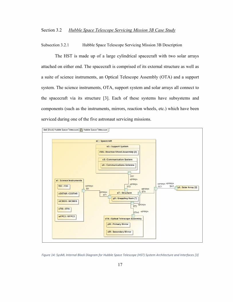
The HST is made up of a large cylindrical spacecraft with two solar arrays
attached on either end. The spacecraft is comprised of its external structure as well as
a suite of science instruments, an Optical Telescope Assembly (OTA) and a support
system. The science instruments, OTA, support system and solar arrays all connect to
the spacecraft via its structure [3]. Each of these systems have subsystems and
components (such as the instruments, mirrors, reaction wheels, etc.) which have been
serviced during one of the five astronaut servicing missions.
Figure 14: SysML Internal Block Diagram for Hubble Space Telescope (HST) System Architecture and Interfaces [3]

18
Selection of Hubble Space Telescope Servicing Mission 3B Solar
Array 3 Removal
Over the course of four days, the astronauts on HST SM3B performed a total of
95 tasks, each including up to 40 task primitives. While utilizing real servicing tasks
for the automated down selection test case provided an opportunity to test down
selection with a larger test case that an individual person could not realistically perform
manually, performing down selection on several thousand task primitives as a first
automated test would be too time consuming when formulating the inputs necessary
for the down selection automation. Instead, because most satellites have solar arrays
that eventually may need to be replaced, and because solar array related tasks have a
medium sized number of task primitives associated with them (approximately twenty),
the Solar Array 3 Removal task served as a representative task to begin testing down
selection. The next chapter demonstrates these two down selection test cases.

19
Chapter 4: Methodology Demonstration
To easily test the down selection methodology on a problem with a known
solution, this thesis began with a smaller manual down selection algorithm
implementation on a simplified satellite servicing scenario. After proving that down
selection could successfully reduce a simplified problem, this thesis expanded to the
larger automated case to prove that down selection can be used to simplify more
realistic engineering design problems.
Manual Algorithm Implementation
Figure 15 shows a step-by-step procedure for generating a manageable set of viable
tool combination solutions. The key points are as follows:
x Steps 1, 2 and 4 input the necessary tools and constraints needed to perform the
down-selection. Steps 1 and 2 comprise the “Design Components” block from
the inference-rule down selection process described in Figure 4. Step 4 is the
“Design Problem Requirements” block. Step 12 outputs the final design space
and shows the engineer all viable design solutions as well as those which are
most optimal from the remaining solution set. This is the “Trade Space
Analysis” block in Figure 4. In between these steps, the algorithm conducts a
series of graph transformations.
x Steps 5, 7, 8, 9 and 11 all reorganize the design options to allow for requirement
and constraint application. Steps 5, 7, 8 and 9 are all part of the “Architecture

20
Connectivity” block in Figure 4. Step 11 is the “Feasible System
Configurations” and the “Feasible System Designs” blocks.
x Steps 3, 6 and 10 all remove design solutions which do not meet system
constraints. Step 3 is the “Component Compatibility” block in Figure 4. Steps
6 and 10 are both the “Requirements Verification” block.

21
Figure 15: Manual Down-Selection Algorithm SysML Activity Diagram
Video and Photographic Footage of Servicing Operations
Pilotte utilized HST SM3B as a basis for studying methods for robotically
servicing satellites [13]. The study reviewed hours of video and photographic footage

22
taken during the Extra Vehicular Activities (EVAs) performed during that mission in
order to create a table of tasks and subtasks executed during SM3B along with the likely
robotic servicing tools necessary to complete each task and sub task activity. A portion
of this table is shown in Table 1.
Table 1: Selection of Tools Needed for Hubble Space Telescope (HST) Robotic Servicing from Pilotte’s Work [13]
Each activity in the table has an associated reference number (“Ref #”), initials
of the Extra Vehicular astronaut who originally performed the task (“EV”)), name
(“Primitive”), larger task it assists in completing (“Task Name”), information on its
necessity for completing the servicing scenario (“Need?”), a general categorization
(“Broad Prim”), the first tool needed (“1st EE”), the number of times the first tool is
needed (“Inst #”), the second tool needed (“2nd EE”) and the number of times the second
tool is needed.
Manually Demonstrating the Down-Selection Methodology
Table 2 shows the initial 19 servicing tool options used to demonstrate this
algorithm (Figure 15, Step 1). Each tool option can be used for either the RESTORE

23
arm type (the arm to be used in NASA’s RESTORE-L servicing mission) or the
DEXTRE arm type (the arm used on RRM). After choosing the RESTORE arm type
for this demonstration (Figure 15, Step 2), tools 4, 7, 13, 14 and 19 were all removed
from the set of tool options (Figure 15, Step 3 is shown in red in Table 2).
Table 2: Initial Set of Tool Options
Option # Tool Functions Arm Force Resolution
Size Step Removed
1 Delicate Pinch
Delicate Pinch RESTORE 1
10
2 Delicate Pinch
Delicate Pinch RESTORE 2
9
3 Delicate Pinch
Delicate Pinch RESTORE 20
15 10
4 Delicate Pinch
Delicate Pinch DEXTRE 10
20 3
5 Welder Welder RESTORE 5 12 6 6 Cutter Cutter RESTORE 13 13 6 7 Pinch Pinch DEXTRE 1 8 3 8 Pinch Pinch RESTORE 6 12 9 Pinch Pinch RESTORE 7 13
10 Bolt Driver
Bolt Driver RESTORE 5
18
11 Bolt Driver
Bolt Driver RESTORE 4
30 6
12 Multi Tool
Delicate Pinch, Pinch and Camera RESTORE 5 22 10
13 Grip Grip DEXTRE 1 1 3 14 Grip Grip DEXTRE 2 2 3 15 Grip Grip RESTORE 5 5 10 16 Grip Grip RESTORE 20 4 17 Camera Camera RESTORE 0 30 5 18 Camera Camera RESTORE 0 21 11 10 19 Camera Camera DEXTRE 0 20 10 3
24
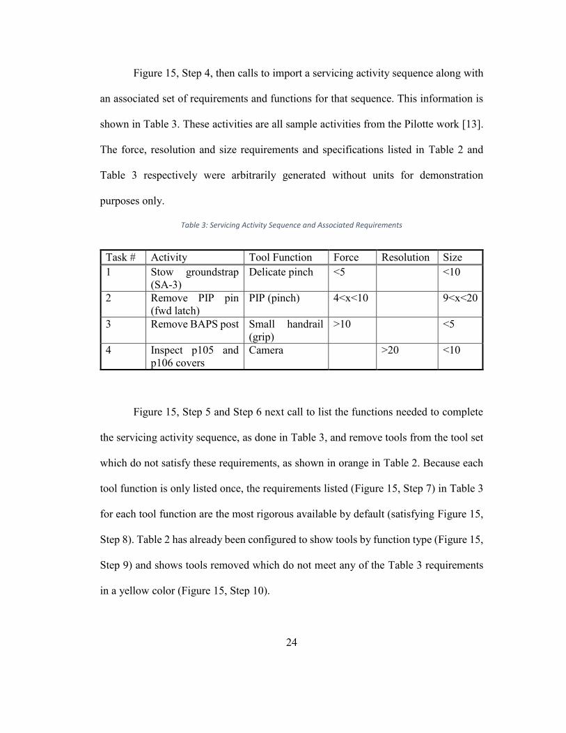
Figure 15, Step 4, then calls to import a servicing activity sequence along with
an associated set of requirements and functions for that sequence. This information is
shown in Table 3. These activities are all sample activities from the Pilotte work [13].
The force, resolution and size requirements and specifications listed in Table 2 and
Table 3 respectively were arbitrarily generated without units for demonstration
purposes only.
Table 3: Servicing Activity Sequence and Associated Requirements
Task # Activity Tool Function Force Resolution Size 1 Stow groundstrap
(SA-3) Delicate pinch <5
<10
2 Remove PIP pin (fwd latch)
PIP (pinch) 4<x<10
9<x<20
3 Remove BAPS post Small handrail (grip)
>10
<5
4 Inspect p105 and p106 covers
Camera
>20 <10
Figure 15, Step 5 and Step 6 next call to list the functions needed to complete
the servicing activity sequence, as done in Table 3, and remove tools from the tool set
which do not satisfy these requirements, as shown in orange in Table 2. Because each
tool function is only listed once, the requirements listed (Figure 15, Step 7) in Table 3
for each tool function are the most rigorous available by default (satisfying Figure 15,
Step 8). Table 2 has already been configured to show tools by function type (Figure 15,
Step 9) and shows tools removed which do not meet any of the Table 3 requirements
in a yellow color (Figure 15, Step 10).

25
Next, the algorithm calls to organize the remaining tools into sets of tools that
satisfy all of the servicing activity functions needed in Table 3. Table 4 shows all 18
viable tool combinations (satisfying Figure 15, Step 11). Its left column lists the
identification number given to each group of tools that satisfy all task primitive
requirements. The right column lists the identification numbers (derived from Table
2’s ID column) for each tool within each tool group identified in the left column.
Though this case has four task primitives, not all tool groups listed include four tools
since some tool groups include a multi tool that performs multiple functions.
Table 4: Viable Tool Combination Groups
Tool Combination ID
Tool Option #
1 1, 8, 12, 16 2 1, 9, 12, 16 3 1, 8, 16, 17 4 1, 9, 16, 17 5 2, 8, 12, 16 6 2, 9, 12, 16 7 2, 8, 16, 17 8 2, 9, 16, 17 9 8, 12, 16 10 9, 12, 16 11 1, 12, 16 12 2, 12, 16 13 12, 16 14 8, 12, 16, 17 15 9, 12, 16, 17 16 1, 12, 16, 17 17 2, 12, 16, 17 18 12, 16, 17

26
Manual Algorithm Implementation Generation of Trade-off Curves
Finally, the algorithm generates tradeoff curves for tool groups versus tool
group mass, total task time and maximum tool power needed (in satisfaction of Figure
15, Step 11). Figure 16, Figure 17, and Figure 18 show these plots and highlight the
tool groups which minimize mass, power, and/or time, in red triangles from the
remaining tools in Table 2’s initial tool set. These highlighted tool groups all lie on the
pareto front, meaning that they are all equally good design solutions. Table 5 shows the
tools’ individual specifications for reference.
Figure 16: Tool Group Mass vs Total Task Time

27
Figure 17: Maximum Tool Power Needed vs Total Task Time
Figure 18: Maximum Tool Power Need vs Total Group Mass

28
Table 5: Viable Tool Specifications
Tool Com-bina-tion #
Tool Func-tions
Mass Power Time to Com-plete Task 1
Time to Com-plete Task 2
Time to Com-plete Task 3
Time to Com-plete Task 4
1 Delicate Pinch
Delicate Pinch
1 19 1
2 Delicate Pinch
Delicate Pinch
2 18 2
8 Pinch Pinch 8 12
8
9 Pinch Pinch 9 11
1
12 Multi Tool
Delicate Pinch, Pinch and Camera
12 8 2 3
7
16 Grip Grip 16 4
10
17 Camera Camera 17 3
6
In short, after listing all available tools and applying inference-rules (Table 2),
the down-selection method whittled the trade space down to a set of 18 viable tool
combinations. These tool combinations were then easily compared with each other on
the bases of mass, power and time.
Manual Algorithm Results Interpretation
From this point, a design solution could be chosen as the best in each plot. In
this particular case, because tool group 13 is the best in Figure 16 and Figure 18 as well
as near optimal in Figure 17, it is likely the best design solution to this sample tool trade
study. Thus, rather than looking at an overwhelmingly large selection of choices, the

29
design engineer has a much smaller and much more manageable decision available
without expending the resources necessary to meet optimization algorithm conditions
or to run more computationally complex optimization algorithms on all of the possible
tools and tool combinations available.
Automated Algorithm Implementation
Because this graph transformation method for systematic trade space down-
selection successfully reduced the trade space from approximately 10,000 options to
18 options with an even smaller number of clear winning options, the method has the
potential to reduce an even larger set of potential design solutions to a smaller set of
easily comparable set of solutions. To do this, the down selection algorithm must be
automated. The next portion of this thesis creates an executable software program
which can run through orders of magnitude more design options for the satellite
servicing scenario. This program also includes methods for accounting for specification
units so that engineers need not standardize units inputting data. In addition, although
the manual algorithm presented in this thesis assumes that a robotic arm has already
been chosen, the following automated version of the algorithm includes multiple arm
options within the trade space.
Scaling the algorithm up to accommodate a larger set of initial tool options and
requirements will require automation. Delgoshaei and Austin [14] and Mosteller et. al.
[15] have performed similar work for transit system and biomedical system
applications respectively. Hennig et. al. [16] also studied space system ontologies,
though not for the robotic servicing application or for direct use in automated

30
algorithms. To improve the accuracy with which requirements are expressed and
evaluated, there is a strong need for computational procedures and tools that can work
with notions of time, space, currency and other units of measure, and incorporated them
into Boolean, equality, and inequality constraints. This automated algorithm builds
upon work that Delgoshaei and Petnga have recently completed [17] [18].
Automated Implementation Tasks, Requirements and Constraints
In order to test down-selection on the tools needed to robotically perform HST
SM3B servicing tasks, SA-3 Removal was chosen as the single overarching task to use
as a sample case for the procedure because SA-3 Removal has relatively few unknown
tools associated with it, and because removing and replacing a solar array will likely
be a common satellite servicing task. Table 6 shows a sampling of the task primitives
needed to complete the SA-3 Removal task. The full set of SA-3 Removal task
primitives is located in Appendix A. Each primitive has associated with it a reference
number, astronaut who performed the primitive, the action completed in the primitive,
a task name, whether or not it is required, a broad primitive categorization, a tool
needed to perform the primitive, the number of times that tool is used for this type of
task primitive, a second tool needed, and the number of times that the second tool is
used for this type of task primitive.

31
Table 6: SA-3 Removal Sample Task Primitives
In order to select tools and arms from a component library which can perform
these task primitives, the task primitives must have component requirements associated
with them. Table 7 shows all of the requirements associated with the task primitives
listed in Table 6. Along with the information initially available with each task primitive,
the requirements figure shows specification for a range or exact value to which a
component must be capable of performing. Task primitives are listed as not needed or
to be performed by a computer were not assigned specifications. Three types of
requirements emerged: requirements related to tool use, arm use, and the interaction
between them. Requirements were assigned to task primitives which were listed as
needed, had known suggested end effectors, and did not list a computer as the suggested
end effector. Those task primitives are assigned requirements received requirements
appropriate to their end effector function. For instance, the task primitive with reference
number 1207 received a torque requirement because bolt drivers primarily perform a
twisting function. All task primitives also received a tool area and arm precision
requirement to account for HST’s physical geometry and architectural limitations.
Table 7: SA-3 Removal Sample Requirements Translation

32
After developing requirements for each task primitive within spreadsheet cells,
the requirements were translated into the more computer readable format, XML. The
following (depicted in Figure 19) is a sample requirement from the requirements in
Table 7 as it was formalized and translated into XML:
<requirement ROIN="1208-AP" level="2" type="Arm Precision"> <title text="1208 Pivot Latch 3 Arm Precision"/> <description> During SA-3 removal, the servicer shall utilize an arm capable of hitting its target within .37 inches to pivot latch 3. </description> <attribute text="Task Number" value="1208"/> <attribute text="Status" value="Active"/> <attribute text="Assigned To" value="Jessica Knizhnik" /> <attribute location = "NASA Goddard" /> <attribute text="Maximum" value="0.37"/> <attribute text="Minimum" value="0"/> <attribute text="Unit" value="in"/> <attribute text="Tool Function" value="Grip Small Object"/> <verifies> <requirement ROIN="SA-3R" /> </verifies> </requirement>
Figure 19: Sample XML Formatted Requirement
All requirements follow a similar format. They have a Requirement Original
Identification Number (ROIN), a level, a type, a title, a description, an associated task
primitive denoted as, “task number,” a status, a person assigned to the requirement, a
requirement location, a maximum value, a minimum value, a unit for those values, and

33
an associated tool function. In the case of the sample requirement here, its ROIN is
1208-AP (denoting that the requirement specifies the arm precision (AP) needed to
perform task primitive 1208), it is a level 2 requirement entitled, “1208 Pivot Latch 3
Arm Precision,” with the text description, “During SA-3 removal, the servicer shall
utilize an arm capable of hitting its target within .37 inches to pivot latch 3.” This
requirement is associated with task primitive 1208, it is an active requirement assigned
to Jessica Knizhnik, it is located at NASA Goddard, it has a maximum of 0.37, a
minimum of 0, both in inches, and requires a component that can perform the function,
“Grip Small Object.”
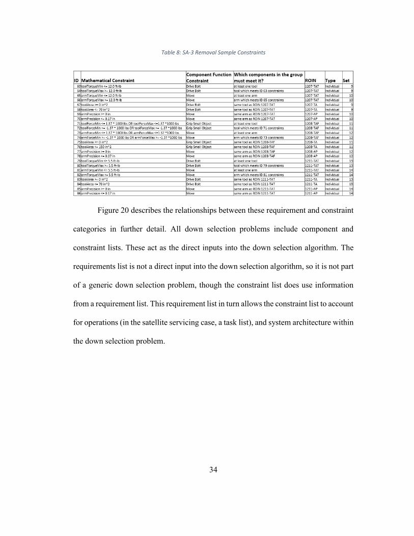
In order to evaluate the requirements, each requirement must be broken into
individual, computer readable constraints. Table 8 shows a sampling of the constraints
associated with the task primitives in Table 6 and the requirements in Table 7. Each
constraint includes an individual ID number, a mathematical constraint (or formula), a
component function constraint, any other constraints for which the same component
must also satisfy, a requirement ROIN which the constraint traces to, a constraint type
(individual constraints denote that the constraint is part of a single set of constraints,
while compound constraints denote that the constraint is part of multiple sets of
constraints), and finally an associated constraint set (where a set groups constraints
which all must be satisfied by the same tool). For this HST SM-3B SA-3 Removal task
case most of mathematical constraints are a combination of inequality and/or Boolean
logic statements, though the mathematical constraints could also include other
statement types for future cases.
34
Table 8: SA-3 Removal Sample Constraints
Figure 20 describes the relationships between these requirement and constraint
categories in further detail. All down selection problems include component and
constraint lists. These act as the direct inputs into the down selection algorithm. The
requirements list is not a direct input into the down selection algorithm, so it is not part
of a generic down selection problem, though the constraint list does use information
from a requirement list. This requirement list in turn allows the constraint list to account
for operations (in the satellite servicing case, a task list), and system architecture within
the down selection problem.

35
Figure 20: Requirement and Constraint Architecture SysML Block Definition Diagram
Finally, in order for these constraints to be computer readable, they were
transferred into an XML format and grouped by set ID (as shown in Figure 21). Each
set specifies the set type (individual vs compound), an ID number for the component
which satisfies all constraints within the set, the function which that component must
satisfy, the referenced component attributes in the component library (in order to
translate them into their associated variable names for the constraint XML file) and
each of the mathematical constraints within the set.
<set id="12" type="Individual"> <component id="C12" function="Move"> <var id="AFMIN" attribute="Force Min" unit="1000 lbs" /> <var id="AFMAX" attribute="Force Max" unit="1000 lbs" />

36
<var id="TPRECISION" attribute="Precision" unit="in" /> </component> <criteria id="73+74" formula="(AFMIN LEQ 1.37 AND AFMIN GEQ -1.37) OR (AFMAX GEQ -1.37 AND AFMAX LEQ 1.37)" derivedfrom="1208-TAF" /> <criteria id="77" formula="(TPRECISION GEQ 0)" derivedfrom="1208-AP"/> <criteria id="78" formula="(TPRECISION LEQ 0.37)" derivedfrom="1208-AP"/> </set>
Figure 21: Sample XML Formatted Constraint Set
Automated Implementation Component Library
In order to utilize down selection to assist with choosing the best component
set, down selection must be applied to a predefined component library. In contrast with
the manual component library, this automated down selection implementation
component library lists both arms and tools as potential components. The manual
implementation component library only lists arms in reference to whether or not they’re
compatible with each individual tool. Instead, compatibility can be checked between
tools and arms by checking that both the cumulative length of the tool and the arm and
whether or not both the tool and the arm can provide the requisite force or torque to
support each other. These compatibility requirements are listed in the “tool + arm”
column of Table 7. Table 9 shows a sample of the components within the component
library. Each component has a component number, type, function(s) it performs, and
associated specifications as outlined in the tool and robotic arm blocks of Figure 10.
The text in Figure 22 shows a sample component entry for a multi tool in this SA-3
Removal case study’s XML component library. It shows the same attributes and values
as the components in Table 9.

37
Table 9: Sample Automated Implementation Components
<component ID="MT1" type="Multi Tool"> <title text="Multi Tool 1"/> <function text="Function 1" value="Drive Bolt" /> <function text="Function 2" value="Inspect" /> <function text="Function 3" value="Pinch" /> <function text="Function 4" value="Delicately Pinch" /> <function text="Function 5" value="Cut" /> <attribute text="Force Min" value="0.0005" unit="1000 lbs" /> <attribute text="Force Max" value="0.0015" unit="1000 lbs" /> <attribute text="Torque Min" value="-6" unit="ft-lb" /> <attribute text="Torque Max" value="30" unit="ft-lb" /> <attribute text="Length" value="3" unit="ft" /> <attribute text="Resolution" value="3" unit="1000 pixels" /> <attribute text="Area" value="70" unit="in^2" /> <attribute text="Mass" value="30" unit="lb" /> <attribute text="Power" value="4" unit="W" /> <attribute text="Task Time" value="3" unit="min" /> </component>
Figure 22: Sample XML Formatted Component
Final Automated Algorithm
Because the set of constraints and a component library to apply them to in the
automated case both have more types (both tool and arm components as well as
compatibility requirements) and attributes associated with them than did the
corresponding requirements set and component library in the manual case, the
automated down selection algorithm grew to accommodate the increased complexity.
Figure 23 shows this updated automated down selection algorithm. The diagram
displays all of the actions that an automated down selection algorithm would require.

38
It therefore begins by processing a user’s inputs, in this case, the HST SM3B Servicer
architecture, the HST architecture, and the HST SM3B task list. Step 1 accounts for all
of this information when creating a requirements list. Ideally, this would be done
automatically, but for the sake of proving the concept, this was done manually as
described in Subsection 4.2.1. Subsection 4.2.1 also describes how to infer a constraint
set from a requirements list as Step 2 prescribes.
Figure 23: Automated Down Selection Algorithm SysML Activity Diagram

39
Steps 3 through 8 describe a set of data transformations where the algorithm
compares the component library with a subset of the constraint set. These steps are
similar to Steps 3 through 11 in the initial manual down selection algorithm (Figure
15). The automated algorithm then removes components that do not meet that subset
of constraints. Step 3 compares the component set with constraints on individual
components, called, “individual constraints,” within the algorithm. As described in
Subsection 4.2.1, these individual constraints link to the needs of task primitives.
Because the algorithm evaluates the components as separate entities at this point with
the goal of creating component groups that meet all requirements, the algorithm needs
only to remove components that do not meet any individual constraints (Step 4). Steps
5 and 6 perform similar functions to compare the component library with the compound
requirements that describe the interaction and compatibility between tools and arms (a
function which the initial manual algorithm does not provide).
Following these compatibility checks, Step 7 in the automated algorithm, pulls
together all possible groups of components from the components left in the component
library after initial down selection. The automated algorithm adds heuristics (“rules of
thumb” or best practices) to assist with this. Though this down selection
implementation does not utilize heuristics, design engineers could choose to impose
additional design constraints not directly traceable to requirements in order to further
reduce the number of final viable design solutions. In future satellite servicing cases,
design engineers may choose to use this step to impose limits on the number of arms
or tools the final viable design solutions may have. Because this is the last stage of

40
down selection, the algorithm now removes all component groups that do not meet the
full constraint list in step 8. This means that though each component in the group does
not need to meet all of the constraints, together the whole group must meet each
constraint in order to perform all task primitives within the servicing task (in the HST
SM3B case study, the SA-3 removal task).
Finally, steps 9 and 10 calculate and then plot figures of merit (for this case
study these are total mass, power, and task time) for each of the component groups
similarly to steps 11 and 12 in the initial manual process. A user can now easily evaluate
groups on the pareto fronts (the optimal design solutions) for each of these plots (mass
vs power, power vs time, and mass vs time) and choose an ideal design solution.
Automated Implementation Results Analysis
The automated implementation also generates a trade space plot consisting of
each remaining viable component group configuration. For the SM3B SA-3 Removal
task, after comparing each component group’s mass, power, and total servicing time,
the pareto front included two out of 1589 potential viable component options (circled
in red in Figure 24).

41
Figure 24: Viable Component Groups after Automated Down Selection
The first component group on the pareto front contains components Arm 2 (A2),
A2, Bolt Driver 11 (BD11), BD7, Multi Tool 1 (MT1), Pinch 3 (P3), Small Handrail
10 (SH10), SH20, and SH20. The second component group on the pareto front contains
components A2, A2, BD11, BD9, MT1, P3, SH10, SH20, and SH20. Both groups have
nine components. No component groups had fewer than nine components, though some
component groups had up 11 components. Each group has two of the same arm as well
as two identical tools to perform task primitives that require two end effectors, 1223
and 1226, appropriately. Both groups also include multi tools, though the multi tools
are unable to meet the requirements of all task primitives. Appendix E lists the top 79
lowest mass solutions down selection determined viable along with their mass, power,

42
servicing time, ID number, and components (all in that order). Though the groups vary
in the tools included, they generally all include a Multi Tool, they all include only Arm
2, and they all have between seven and nine tools (much larger than RRM’s four tools).
Implementation Comparison
After testing down selection manually on a small scale and then expanding it to
accommodate a larger design problem by automating the algorithm, this methodology
suggests that down selection can be applied to both small and large problems with
similar results. Though both problems had vastly different numbers of potential design
solutions, down selection successfully reduced both problem spaces to less than ten
ideal solutions. In order to automate the down selection algorithm developed for a
manual implementation, the algorithm inputs had to be expanded and more rigorously
defined. The manual implementation implied that constraints might exist when
accounting for each tool’s needed operating range for each task primitive, but down
selection requires explicitly defined constraints to operate automatically.

43
Chapter 5: Conclusions and Future Work
Implications
Implications for General Trade Studies
The manual method for systematic trade space down-selection presented in this
thesis successfully presented a set of 18 servicing tool group options for a set of four
servicing task primitives from an initial set of 19 potential servicing tools (as well as
an additional option to not bring a tool to perform a particular task primitive),
amounting to an initial 8855 potential servicing tool group combinations. (8855 is
derived from the formula for the number of potential tool combinations available when
choosing up to four tools from a set of 19 where order matters, but each tool can be
used more than one time: ∑ ( )!!( )! .) Of those 18 servicing tool groups, an engineer
could then easily visualize the seven best group options as measured against mass,
power and time and use engineering judgement to pick the single ultimate design
solution. This systematic trade space down-selection method shows promise for
quickly reducing an even larger, more intractable problem to one that is easily solvable.
The manual down selection method reduced the number of options in the trade space
by four orders of magnitude.
Similarly, the automated method for systematic trade space down-selection
presented in this thesis successfully presented a set of approximately 1500 servicing
component group options for a set of 20 task primitives from an initial set of 162
potential component options (as well as an additional option to not bring a tool to

44
perform a particular task primitive). This means that initially an engineer would be
choosing from ∑ ( )!!( )! ≈ 2 ∗ 10 component set options. Like the manual
implementation, the automated implementation also allowed an engineer to visually
reduce the viable component sets further. In this particular case, the pareto front only
holds two options. This means that the automated down selection method successfully
reduced the trade space down by 26 orders of magnitude.
The number of viable design solutions left after down selection and present on
the pareto front seems to be highly dependent on the number of components in the
component library as well as on the number and nature of the constraints. Because the
components and constraints utilized in this case study were created, in part, arbitrarily,
rather than for particular tools, arms, or client satellite specifications, the problem was
easily over constrained. With component and constraint metadata associated with real
tools, arms, and client satellites, it is possible that the number of viable solutions on the
pareto front may not be as limited as in this case study. It is also possible that the
optimal design solutions include fewer tools (thus ultimately further reducing mass,
power, and time).
While the manual down selection implementation produced a significant
reduction in options within the trade space, the automated implementation exceeded
that reduction by significant orders of magnitude. This opens up the possibility that as
the component library within the trade space increases, as long as a user specifies
enough constraints, down selection can still produce a similar final reduction in the
trade space. Both the manual and automated implementations reduced the number of

45
design solutions below 10. It seems likely that with enough constraints applied to the
component library, down selection combined with visual data analysis can continue to
reduce most trade spaces down to less than 10 design solutions.
Implications for Satellite Servicing
Though the requirements and constraints in this thesis are examples, the viable
design option component groups on the pareto front in this thesis do point towards a
final design solution with one component per required end effector function. The
smallest number of components for any viable component group identified in this thesis
is seven, the same number of unique required functions. Though one of these
components is an arm, the other six are tools. That is two more tools for a single task
than the RRM uses to test potential satellite servicing operations for a set of potential
task primitives. More multi tools with broad component operation ranges will likely be
needed to reduce the number of individual tools necessary for each servicer to carry.
The number of components required may plateau as the number of task primitives
increases since there seem to be a few basic types of task primitives repeated over all
of SM3B tasks. Further down selection tests with multiple tasks would be required.
Another option to reduce the number of servicer tools is to build client satellites with
robust designs that can all operate under the same constraint ranges with a limited
number of required end effector functions. This may be an unlikely possibility in the
future when engineers may design with servicing in mind, but it is certainly not an
option for previously built satellites already in space. Robust multi-functional

46
components will be needed to service historic satellites even if future client satellites
are designed with servicing in mind.
Future Work
Down selection has the potential to allow engineers to systematically explore
trade spaces without developing the parameters necessary to easily and efficiently
utilize optimization algorithms. However, performing down selection must be less
labor and time intensive for it to be a viable and useful option.
In order to implement an automated down selection algorithm for this thesis,
the data formatting into XML required approximately 48 hours of repetitive manual
work to complete after the technical detail of the components, requirements, and
constraints had been decided. This time must be reduced for down selection
implementation to become a viable option for trade space exploration. Future studies
should explore other formats for storing and formatting data model metadata for
examination and analysis by down selection (and/or other semantic model rules). The
metadata recorded for this thesis were initially organized within the human readable
spreadsheet (specifically, Excel) and SysML formats. Because most engineers utilize
spreadsheets for tracking data, and because SysML shows promise for tracking system
elements, metadata, and relationships, a data model should be creatable directly from
either or both of these formats.
Automatically translating requirements into constraints will also be necessary
to reasonably implement down selection. Natural language processing such as Carney’s
2017 work in parsing requirements to check them for completeness may be extensible

47
to constraint extraction. This would allow engineers to write requirements as they
would normally write them before performing down selection. In order for engineers
to adopt down selection, the process that they use to explore their trade space will likely
need to mimic the process that they regularly use to ease the transition to using a new
method.
Additionally, automated down selection, together with various versions of the
HST SM3B case study, required between five hours and five days to generate a viable
design solutions list. A run time of a few hours may be a reasonable time frame for
engineers to wait for results, but engineers are not likely to use down selection if its run
time is on the order of a few days. Run time varied with the number of components,
the number of constraints, and the computer running the algorithm. Future studies
should investigate the ideal ratio of components to constraints and whether down
selection is feasible on a personal computer rather than a super computer. Both of these
studies should aim to reduce run time.
This thesis included five arms, and 157 tools. Because each task primitive
required the same arm, the arm specifications and availability acted as limiting factors
for the final viable design solution set. Further work should also be done to understand
the ideal number of components and constraints to produce a pareto front less limited
than the one in this study. Considerations should include how many constraints will be
needed, how strict each constraint should be, how many components are appropriate,
which type of components are appropriate, and how wide a spread of component
specifications down selection can accommodate.

48
Finally, this thesis focuses on a simplified HST SM3B servicing case study.
Future studies should verify that down selection applies to other cases and that the
associated metadata developed for this thesis applies to other semantic rule driven
models. Future studies should also begin to incorporate constraints and parameters
associated with more complex physics in order to expand down selection’s verified
utility.

49
Appendices
Appendix A: Servicing Mission 3b Solar Array 3 Removal Task Primitives [13]

50

51
Appendix B: Automated Implementation Component Library
ID# Type Func-tion(s)
Force Min
Force Max
Torque Min
Torque Max
Length
Res-olu-tion Area
Precision DoF Mass
Po-wer
Time (m)
A1 Arm move 0 0.0005 0 18 20 0.1 6 50 10 3
A2 Arm move 0.002 0.5 -50 30 25 0.1
5 7 60 9 0.5
A3 Arm move 0.001 0.0015 -15 40 30 0.2 6 40 8 1
A4 Arm move 0 0.0015 -40 0 35 0.3 5 30 7 2
A5 Arm move 0.001 0.0015 -10 10 40 0.5 6 70 6 0.75
MT1 Multi Tool
Drive Bolt, Inspect, pinch, delicately pinch, cut 0.0005 0.0015 -6 30 3 3 70 30 4 3
MT2 Multi Tool
Drive Bolt, Inspect, delicately pinch, grasp pip 0.002 0.005 -6 6 4 3 60 29 3 2.5
MT3 Multi Tool
Drive Bolt, Inspect, cut, delicately pinch 0.001 0.003 -2 15 5 3 100 28 2 2
MT4 Multi Tool
Drive Bolt, Inspect, grasp pip 0.001 0.002 0 16 4 3 150 27 1 1.5
MT5 Multi Tool
Drive Bolt, Inspect, delicately pinch 0.003 0.007 -1.5 1.5 3 5 200 26 2 1
MT6 Multi Tool
Drive Bolt, Inspect, cut 0.002 0.0025 -30 30 2 2 250 25 3 0.5
MT7 Multi Tool
Drive Bolt, Inspect, pinch 0.0005 0.0006 -12 29 1 6 300 24 4 1
MT8 Multi Tool
Inspect, pinch, cut 0.001 0.0011 2 5 200 23 5 1.5
MT9 Multi Tool
Inspect, delicately pinch, grasp pip 0.0015 0.0035 3 3 300 22 6 2

52
ID# Type Func-tion(s)
Force Min
Force Max
Torque Min
Torque Max
Length
Res-olu-tion Area
Precision DoF Mass
Po-wer
Time (m)
C1 Camera Inspect 4 4 130 21 7 2.5
C2 Camera Inspect 5 5 140 20 8 3
C3 Camera Inspect 4 6 150 19 9 3.5
C4 Camera Inspect 3 8 170 18 10 4
C5 Camera Inspect 2 8 190 17 9 4.5
C6 Camera Inspect 1 10 200 16 8 5
BD1 Drive Bolt
Drive Bolt 0 17 2 50 15 7 4.5
BD2 Drive Bolt
Drive Bolt 0.5 17.5 3 300 14 6 4
BD3 Drive Bolt
Drive Bolt 0 40 4 60 13 5 3.5
BD4 Drive Bolt
Drive Bolt -1 1 5 290 12 4 3
BD5 Drive Bolt
Drive Bolt -7 30 4 70 11 3 2.5
BD6 Drive Bolt
Drive Bolt -13 28 3 280 10 2 2
BD7 Drive Bolt
Drive Bolt -2 21.5 2 80 11 1 1.5
BD8 Drive Bolt
Drive Bolt -22 22 1 270 12 1 1
BD9 Drive Bolt
Drive Bolt -6 40 2 90 13 2 0.5
BD10 Drive Bolt
Drive Bolt -10 10 3 260 14 3 1
BD11 Drive Bolt
Drive Bolt -30 30 4 100 15 4 1.5
BD12 Drive Bolt
Drive Bolt -30 30 5 250 16 5 2
BD13 Drive Bolt
Drive Bolt
-24.
5 24.5 4 110 17 6 2.5
BD14 Drive Bolt
Drive Bolt -25 25 3 240 18 7 3
BD15 Drive Bolt
Drive Bolt -17 18 2 120 19 8 3.5
BD16 Drive Bolt
Drive Bolt -5.5 5.5 1 230 20 9 4
BD17 Drive Bolt
Drive Bolt -30 0 2 130 21 10 4.5
BD18 Drive Bolt
Drive Bolt -12 10 3 220 22 9 5
BD19 Drive Bolt
Drive Bolt -10 12 4 140 23 8 4.5
BD20 Drive Bolt
Drive Bolt -5 1.5 5 210 24 7 4
BD21 Drive Bolt
Drive Bolt -10 20 4 150 25 6 3.5
BD22 Drive Bolt
Drive Bolt -30 30 3 200 26 5 3
BD23 Drive Bolt
Drive Bolt -10 5 2 160 27 4 2.5
BD24 Drive Bolt
Drive Bolt 0 5.5 1 190 28 3 2
SH1 Small Handrail
grip small object -2 -1.81 2 300 29 2 1.5
SH2 Small Handrail
grip small object -1.9 -1.68 3 50 30 1 1

53
ID# Type Func-tion(s)
Force Min
Force Max
Torque Min
Torque Max
Length
Res-olu-tion Area
Precision DoF Mass
Po-wer
Time (m)
SH3 Small Handrail
grip small object -1.8 -1.55 4 290 29 1 0.5
SH4 Small Handrail
grip small object -1.7 -1.42 5 60 28 2 1
SH5 Small Handrail
grip small object -1.6 -1.29 4 280 27 3 1.5
SH6 Small Handrail
grip small object -1.5 -1.16 3 70 26 4 2
SH7 Small Handrail
grip small object -1.4 -1.03 2 270 25 5 2.5
SH8 Small Handrail
grip small object -1.3 -0.9 1 80 24 6 3
SH9 Small Handrail
grip small object -1.2 -0.77 2 260 23 7 3.5
SH10 Small Handrail
grip small object -1.1 -0.64 3 90 22 8 4
SH11 Small Handrail
grip small object -1 -0.51 4 250 21 9 4.5
SH12 Small Handrail
grip small object -0.9 -0.38 5 100 20 10 5
SH13 Small Handrail
grip small object -0.8 -0.25 4 240 19 9 4.5
SH14 Small Handrail
grip small object -0.7 -0.12 3 110 18 8 4
SH15 Small Handrail
grip small object -0.6 0.01 2 230 17 7 3.5
SH16 Small Handrail
grip small object -0.5 0.14 1 120 16 6 3
SH17 Small Handrail
grip small object -0.4 0.27 2 220 15 5 2.5
SH18 Small Handrail
grip small object -0.3 0.4 3 130 14 4 2
SH19 Small Handrail
grip small object -0.2 0.53 4 210 13 3 1.5
SH20 Small Handrail
grip small object -0.1 0.66 5 140 12 2 1
SH21 Small Handrail
grip small object 0 0.79 4 200 11 1 0.5
SH22 Small Handrail
grip small object 0.1 0.92 3 150 10 1 1
SH23 Small Handrail
grip small object 0.2 1.05 2 190 11 2 1.5
SH24 Small Handrail
grip small object 0.3 1.18 1 160 12 3 2

54
ID# Type Func-tion(s)
Force Min
Force Max
Torque Min
Torque Max
Length
Res-olu-tion Area
Precision DoF Mass
Po-wer
Time (m)
SH25 Small Handrail
grip small object 0.4 1.31 2 180 13 4 2.5
SH26 Small Handrail
grip small object 0.5 1.44 3 170 14 5 3
SH27 Small Handrail
grip small object 0.6 1.57 4 170 15 6 3.5
SH28 Small Handrail
grip small object 0.7 1.7 5 180 16 7 4
SH29 Small Handrail
grip small object 0.8 1.83 4 160 17 8 4.5
SH30 Small Handrail
grip small object 0.9 1.96 3 190 18 9 5
SH31 Small Handrail
grip small object 1 2.09 2 150 19 10 4.5
SH32 Small Handrail
grip small object 1.1 2.22 1 200 20 9 4
SH33 Small Handrail
grip small object 1.2 2.35 2 140 21 8 3.5
SH34 Small Handrail
grip small object 1.3 2.48 3 210 22 7 3
SH35 Small Handrail
grip small object 1.4 2.61 4 130 23 6 2.5
SH36 Small Handrail
grip small object 1.5 2.74 5 220 24 5 2
SH37 Small Handrail
grip small object 1.6 2.87 4 120 25 4 1.5
SH38 Small Handrail
grip small object 1.7 3 3 230 26 3 1
LH1 Large Handrail
grip large object -10 -2 2 300 27 2 0.5
LH2 Large Handrail
grip large object -9.4 -1.4 1 50 28 1 1
LH3 Large Handrail
grip large object -8.8 -0.8 2 290 29 1 1.5
LH4 Large Handrail
grip large object -8.2 -0.2 3 60 30 2 2
LH5 Large Handrail
grip large object -7.6 0.4 4 280 29 3 2.5
LH6 Large Handrail
grip large object -7 1 5 70 28 4 3
LH7 Large Handrail
grip large object -6.4 1.6 4 270 27 5 3.5
LH8 Large Handrail
grip large object -5.8 2.2 3 80 26 6 4

55
ID# Type Func-tion(s)
Force Min
Force Max
Torque Min
Torque Max
Length
Res-olu-tion Area
Precision DoF Mass
Po-wer
Time (m)
LH9 Large Handrail
grip large object -5.2 2.8 2 260 25 7 4.5
LH10 Large Handrail
grip large object -4.6 3.4 1 90 24 8 5
LH11 Large Handrail
grip large object -4 4 2 250 23 9 4.5
LH12 Large Handrail
grip large object -3.4 4.6 3 100 22 10 4
LH13 Large Handrail
grip large object -2.8 5.2 4 240 21 9 3.5
LH14 Large Handrail
grip large object -2.2 5.8 5 110 20 8 3
LH15 Large Handrail
grip large object -1.6 6.4 4 230 19 7 2.5
LH16 Large Handrail
grip large object -1 7 3 120 18 6 2
LH17 Large Handrail
grip large object -0.4 7.6 2 220 17 5 1.5
LH18 Large Handrail
grip large object 0.2 8.2 1 130 16 4 1
LH19 Large Handrail
grip large object 0.8 8.8 2 210 15 3 0.5
LH20 Large Handrail
grip large object 1.4 9.4 3 140 14 2 1
LH21 Large Handrail
grip large object 2 10 4 200 13 1 1.5
P1 Pinch grasp pip 0 0.001 5 40 12 1 2
P2 Pinch grasp pip 0.0005 0.0015 4 45 11 2 2.5
P3 Pinch grasp pip 0.001 0.002 3 50 10 3 3
P4 Pinch grasp pip 0.0015 0.0025 2 55 11 4 3.5
P5 Pinch grasp pip 0.002 0.003 1 60 12 5 4
P6 Pinch grasp pip 0.0025 0.0035 2 65 13 6 4.5
P7 Pinch grasp pip 0.003 0.004 3 70 14 7 5
P8 Pinch grasp pip 0.0035 0.0045 4 75 15 8 4.5
P9 Pinch grasp pip 0.004 0.005 5 80 16 9 4
P10 Pinch grasp pip 0.0045 0.0055 4 85 17 10 3.5
P11 Pinch grasp pip 0.005 0.006 3 90 18 9 3
P12 Pinch grasp pip 0.0055 0.0065 2 95 19 8 2.5
P13 Pinch grasp pip 0.006 0.007 1 100 20 7 2

56
ID# Type Func-tion(s)
Force Min
Force Max
Torque Min
Torque Max
Length
Res-olu-tion Area
Precision DoF Mass
Po-wer
Time (m)
DP1 Delicate Pinch
delicately pinch 0 0.0003 2 50 21 6 1.5
DP2 Delicate Pinch
delicately pinch 0.0002 0.0006 3 100 22 5 1
DP3 Delicate Pinch
delicately pinch 0.0004 0.0009 4 55 23 4 0.5
DP4 Delicate Pinch
delicately pinch 0.0006 0.0012 5 95 24 3 1
DP5 Delicate Pinch
delicately pinch 0.0008 0.0015 4 60 25 2 1.5
DP6 Delicate Pinch
delicately pinch 0.001 0.0018 3 90 26 1 2
DP7 Delicate Pinch
delicately pinch 0.0012 0.0021 2 65 27 1 2.5
DP8 Delicate Pinch
delicately pinch 0.0014 0.0024 1 85 28 2 3
DP9 Delicate Pinch
delicately pinch 0.0016 0.0027 2 70 29 3 3.5
DP10 Delicate Pinch
delicately pinch 0.0018 0.003 3 80 30 4 4
DP11 Delicate Pinch
delicately pinch 0.002 0.0033 4 75 29 5 4.5
DP12 Delicate Pinch
delicately pinch 0.0022 0.0036 5 75 28 6 5
DP13 Delicate Pinch
delicately pinch 0.0024 0.0039 4 80 27 7 4.5
DP14 Delicate Pinch
delicately pinch 0.0026 0.0042 3 70 26 8 4
DP15 Delicate Pinch
delicately pinch 0.0028 0.0045 2 85 25 9 3.5
DP16 Delicate Pinch
delicately pinch 0.003 0.0048 1 65 24 10 3
DP17 Delicate Pinch
delicately pinch 0.0032 0.0051 2 90 23 9 2.5
DP18 Delicate Pinch
delicately pinch 0.0034 0.0054 3 60 22 8 2
DP19 Delicate Pinch
delicately pinch 0.0036 0.0057 4 95 21 7 1.5
DP20 Delicate Pinch
delicately pinch 0.0038 0.006 5 55 20 6 1
DP21 Delicate Pinch
delicately pinch 0.004 0.0063 4 100 19 5 0.5
W1 Welder weld 3 50 18 4 1
W2 Welder weld 2 300 17 3 1.5

57
ID# Type Func-tion(s)
Force Min
Force Max
Torque Min
Torque Max
Length
Res-olu-tion Area
Precision DoF Mass
Po-wer
Time (m)
W3 Welder weld 1 60 16 2 2
W4 Welder weld 2 290 15 1 2.5
W5 Welder weld 3 70 14 1 3
W6 Welder weld 4 280 13 2 3.5
C1 Cutter cut 0 0.0004 5 80 12 3 4
C2 Cutter cut 0.0003 0.0008 4 270 11 4 4.5
C3 Cutter cut 0.0006 0.0012 3 90 10 5 5
C4 Cutter cut 0.0009 0.0016 2 260 11 6 4.5
C5 Cutter cut 0.0012 0.002 1 100 12 7 4
C6 Cutter cut 0.0015 0.0024 2 250 13 8 3.5
C7 Cutter cut 0.0018 0.0028 3 110 14 9 3
C8 Cutter cut 0.0021 0.0032 4 240 15 10 2.5
C9 Cutter cut 0.0024 0.0036 5 120 16 9 2
C10 Cutter cut 0.0027 0.004 4 230 17 8 1.5
C11 Cutter cut 0.003 0.0044 3 130 18 7 1
C12 Cutter cut 0.0033 0.0048 2 220 19 6 0.5
C13 Cutter cut 0.0036 0.0052 1 140 20 5 1
C14 Cutter cut 0.0039 0.0056 2 210 21 4 1.5
C15 Cutter cut 0.0042 0.006 3 150 22 3 2
C16 Cutter cut 0.0045 0.0064 4 200 23 2 2.5
C17 Cutter cut 0.0048 0.0068 5 160 24 1 3
C18 Cutter cut 0.0051 0.0072 4 190 25 1 3.5
C19 Cutter cut 0.0054 0.0076 3 170 26 2 4
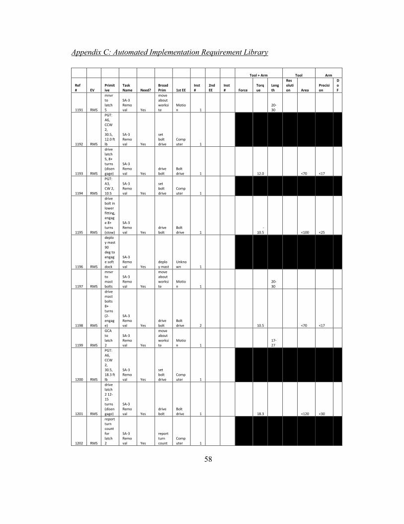
58
Appendix C: Automated Implementation Requirement Library
Tool + Arm Tool Arm
Ref # EV
Primitive
Task Name Need?
Broad Prim 1st EE
Inst #
2nd EE
Inst # Force
Torque
Length
Resolution Area
Precision
DoF
1191 RMS
mnvr to latch 5
SA-3 Removal Yes
move about worksite
Motion 1
20-30
1192 RMS
PGT: A6, CCW 2, 30.5, 12.0 ft lb
SA-3 Removal Yes
set bolt drive
Computer 1
1193 RMS
drive latch 5, 8+ turns (disengage)
SA-3 Removal Yes
drive bolt
Bolt drive 1 12.0 <70 <17
1194 RMS
PGT: A3, CW 2, 10.5
SA-3 Removal Yes
set bolt drive
Computer 1
1195 RMS
drive bolt in lower fitting, engage 8+ turns (stow)
SA-3 Removal Yes
drive bolt
Bolt drive 1
-10.5 <100 <25
1196 RMS
deploy mast 90 deg to engage soft dock
SA-3 Removal Yes
deploy mast
Unknown 1
1197 RMS
mnvr to mast bolts
SA-3 Removal Yes
move about worksite
Motion 1
20-30
1198 RMS
drive mast bolts 8+ turns (2-engage)
SA-3 Removal Yes
drive bolt
Bolt drive 2 10.5 <70 <17
1199 RMS
GCA to latch 2
SA-3 Removal Yes
move about worksite
Motion 1
17-27
1200 RMS
PGT: A6, CCW 2, 30.5, 18.3 ft lb
SA-3 Removal Yes
set bolt drive
Computer 1
1201 RMS
drive latch 2 12-15 turns (disengage)
SA-3 Removal Yes
drive bolt
Bolt drive 1 18.3 <120 <30
1202 RMS
report turn count for latch 2
SA-3 Removal Yes
report turn count
Computer 1

59
Tool + Arm Tool Arm
Ref # EV
Primitive
Task Name Need?
Broad Prim 1st EE
Inst #
2nd EE
Inst # Force
Torque
Length
Resolution Area
Precision
DoF
1203 RMS
GCA to latch 1
SA-3 Removal Yes
move about worksite
Motion 1
16-26
1204 FF
translate to RAC, latch 3
SA-3 Removal Yes
move about worksite
Motion 1
18-28
1205 FF
ingrass aft PFR
SA-3 Removal No
Large handrail 1
-.00162 - 1.79 <250 <62
1206 FF
PGT: A6, CCW 2, 30.5, 12.0 ft lb
SA-3 Removal Yes
set bolt drive
Computer 1
1207 FF
drive latch 3 until clamp clears tang, 7-9 turns (release)
SA-3 Removal Yes
drive bolt
Bolt drive 1 12.0 <70 <17
1208 FF
pivot latch 3 to clear tang
SA-3 Removal Yes
pivot latch
Small Handrail 1
-1.37 - 1.37 <150 <37
1209 FF
tether to tang
SA-3 Removal No
Tether tool 1
1210 FF
PGT: A2, CCW 2, 5.5
SA-3 Removal Yes
set bolt drive
Computer 1
1211 FF
drive tang bolts 9-10 turns (2-disengage
SA-3 Removal Yes
drive bolt
Bolt drive 2 5.5 <70 <17
1212 FF
stow to tang on CSS
SA-3 Removal Yes
stow tang
Bolt drive 1
Small handrail 1
1213 FF
PGT: A2, CW 2, 5.5
SA-3 Removal Yes
set bolt drive
Computer 1
1214 FF
drive tang bolts 9-10 turns (2-disengage
SA-3 Removal Yes
drive bolt
Bolt drive 2 -5.5 <100 <25
1215 FF
pivot latch 3 to stowed position
SA-3 Removal Yes
pivot latch
Small Handrail 1
-1.37 - 1.37 <170 <42

60
Tool + Arm Tool Arm
Ref # EV
Primitive
Task Name Need?
Broad Prim 1st EE
Inst #
2nd EE
Inst # Force
Torque
Length
Resolution Area
Precision
DoF
1216 FF
install PIP pin
SA-3 Removal Yes
install/remove PIP PIP 1
0.002 - 0.005 <60 <15
1217 FF
deploy MLI flap over tang interferance
SA-3 Removal Yes
deploy MLI
Delicate Pinch 1
0.001 - 0.002 <70 <17
1218 FF
PGT: A6, CCW 2, 30.5, 8.7 ft lb
SA-3 Removal Yes
set bolt drive
Computer 1
1219 FF
drive latch 4 10-15 turns (release)
SA-3 Removal Yes
drive bolt
Bolt drive 1 8.7 <150 <37
1220 FF
report turn count for latch 4
SA-3 Removal Yes
report turn count
Computer 1
1221 FF
grasp SA during latch 1 release (stabilize)
SA-3 Removal No
Small Handrail 1
Small handrail 1
1222 RMS
PGT: A6, CCW 2, 30.5, 24.0 ft lb
SA-3 Removal Yes
set bolt drive
Computer 1
1223 RMS
drive latch 1, 19+ turns (release)
SA-3 Removal Yes
drive bolt
Bolt drive 1
Small handrail 1
-1.37 - 1.37 24.0
<100, <200
<25, <50
1224 RMS
mnvr to SA-3 top handrails at c.g. mark
SA-3 Removal Yes
move about worksite
Motion 1
25-35
1225 RMS
remove SA-3 (slide out contingency slots)
SA-3 Removal No
Small Handrail 1
Small handrail 1
1226 FF remove SA-3
SA-3 Removal Yes
install/remove SA
Small Handrail 1
Small handrail 1
2X 0.5-2.5 <200 <20

61
Appendix D: Automated Implementation Constraint Set
ID Mathematical Constraint Component Function Constraint
Which components in the group must meet it?
ROIN Type Set
1 toolLength + armLength >= 20 ft Drive Bolt + Move tool and arm which meet ROIN 1193 constraints
1191-TAL
Compound 1,2
2 toolLength + armLength <= 30 ft Drive Bolt + Move tool and arm which meet ID 1 constraints
1191-TAL
Compound 1,2
3 toolLength + armLength >= 20 ft Drive Bolt + Move tool and arm which meet ROIN 1195 constraints
1191-TAL
Compound 3,4
4 toolLength + armLength <= 30 ft Drive Bolt + Move tool and arm which meet ID 3 constraints
1191-TAL
Compound 3,4
5 toolTorqueMin <= 12 ft-lb Drive Bolt at least one tool 1193-TAT
Individual 1
6 toolTorqueMax >= 12 ft-lb Drive Bolt tool which meets ID 5 constraints
1193-TAT
Individual 1
7 armTorqueMin <=12 ft-lb Move at least one arm 1193-TAT
Individual 2
8 armTorqueMax >= 12 ft-lb Move arm which meets ID 7 constraints
1193-TAT
Individual 2
9 toolArea >= 0 in^2 Drive Bolt same tool as ROIN 1193-TAT 1193-TA Individual 1
10 toolArea <= 70 in^2 Drive Bolt same tool as ROIN 1193-TAT 1193-TA Individual 1
11 armPrecision >= 0 in Move same arm as ROIN 1193-TAT 1193-AP Individual 2
12 armPrecision <= 0.17 in Move same arm as ROIN 1193-TAT 1193-AP Individual 2
13 toolTorqueMin <= -10.5 ft-lb Drive Bolt at least one tool 1195-TAT
Individual 3
14 toolTorqueMax >= -10.5 ft-lb Drive Bolt tool which meets ID 13 constraints
1195-TAT
Individual 3
15 armTorqueMin <= -10.5 ft-lb Move at least one arm 1195-TAT
Individual 4
16 armTorqueMax >= -10.5 ft-lb Move arm which meets ID 15 constraints
1195-TAT
Individual 4
17 toolArea >= 0 in^2 Drive Bolt same tool as ROIN 1195-TAT 1195-TA Individual 3
18 toolArea <= 100 in^2 Drive Bolt same tool as ROIN 1195-TAT 1195-TA Individual 3
19 armPrecision >= 0 in Move same arm as ROIN 1195-TAT 1195-AP Individual 4
20 armPrecision <= 0.25 in Move same arm as ROIN 1195-TAT 1195-AP Individual 4
21 toolLength + armLength >= 20 ft Drive Bolt + Move tool and arm which meet ROIN 1198 constraints
1197-TAL
Compound 5,6
22 toolLength + armLength <= 30 ft Drive Bolt + Move tool and arm which meet ID 21 constraints
1197-TAL
Compound 5,6
23 toolTorqueMin <= 10.5 ft-lb Drive Bolt at least one tool 1198-TAT
Individual 5
24 toolTorqueMax >= 10.5 ft-lb Drive Bolt tool which meets ID 23 constraints
1198-TAT
Individual 5
25 armTorqueMin <= 10.5 ft-lb Move at least one arm 1198-TAT
Individual 6
26 armTorqueMax >= 10.5 ft-lb Move arm which meets ID 25 constraints
1198-TAT
Individual 6
27 toolArea >= 0 in^2 Drive Bolt same tool as ROIN 1198-TAT 1198-TA Individual 5
28 toolArea <= 70 in^2 Drive Bolt same tool as ROIN 1198-TAT 1198-TA Individual 5
29 armPrecision >= 0 in Move same arm as ROIN 1198-TAT 1198-AP Individual 6
30 armPrecision <= 0.17 in Move same arm as ROIN 1198-TAT 1198-AP Individual 6
31 toolLength + armLength >= 17 ft Drive Bolt + Move tool and arm which meet ROIN 1201 constraints
1199-TAL
Compound 7,8
32 toolLength + armLength <= 27 ft Drive Bolt + Move tool and arm which meet ID 31 constraints
1199-TAL
Compound 7,8
33 toolTorqueMin <= 18.3 ft-lb Drive Bolt at least one tool 1201-TAT
Individual 7

62
34 toolTorqueMax >= 18.3 ft-lb Drive Bolt tool which meets ID 33 constraints
1201-TAT
Individual 7
35 armTorqueMin <= 18.3 ft-lb Move at least one arm 1201-TAT
Individual 8
36 armTorqueMax >= 18.3 ft-lb Move arm which meets ID 35 1201-TAT
Individual 8
37 toolArea >= 0 in^2 Drive Bolt same tool as ROIN 1201-TAT 1201-TA Individual 7
38 toolArea <= 120 in^2 Drive Bolt same tool as ROIN 1201-TAT 1201-TA Individual 7
39 armPrecision >= 0 in Move same arm as ROIN 1201-TAT 1201-AP Individual 8
40 armPrecision <= 0.3 in Move same arm as ROIN 1201-TAT 1201-AP Individual 8
41 toolLength + armLength >= 16 ft Drive Bolt + Move tools and arms which meet ROIN 1204 constraints
1203-TAL
Compound
42 toolLength + armLength <= 26 ft Drive Bolt + Move tools and arms which meet ID 41 constraints
1203-TAL
Compound
43 toolLength + armLength >= 18 ft Grip Small Object + Move
tool and arm which meet ROIN 1207 constraints
1204-TAL
Compound 9,10
44 toolLength + armLength <= 28 ft Grip Small Object + Move
tool and arm which meet ID 43 constraints
1204-TAL
Compound 9,10
45 toolLength + armLength >= 18 ft Grip Small Object + Move
tool and arm which meet ROIN 1208 constraints
1204-TAL
Compound 11,12
46 toolLength + armLength <= 28 ft Grip Small Object + Move
tool and arm which meet ID 45 constraints
1204-TAL
Compound 11,12
47 toolLength + armLength >= 18 ft Drive Bolt + Move tool and arm which meet ROIN 1211 constraints
1204-TAL
Compound 13,14
48 toolLength + armLength <= 28 ft Drive Bolt + Move tool and arm which meet ID 47 constraints
1204-TAL
Compound 13,14
49 toolLength + armLength >= 18 ft Drive Bolt + Move tool and arm which meet ROIN 1214 constraints
1204-TAL
Compound 15,16
50 toolLength + armLength <= 28 ft Drive Bolt + Move tool and arm which meet ID 49 constraints
1204-TAL
Compound 15,16
51 toolLength + armLength >= 18 ft Grip Small Object + Move
tool and arm which meet ROIN 1215 constraints
1204-TAL
Compound 17,18
52 toolLength + armLength <= 28 ft Grip Small Object + Move
tool and arm which meet ID 51 constraints
1204-TAL
Compound 17,18
53 toolLength + armLength >= 18 ft Grasp PIP + Move tool and arm which meet ROIN 1216 constraints
1204-TAL
Compound 19,20
54 toolLength + armLength <= 28 ft Grasp PIP + Move tool and arm which meet ID 53 constraints
1204-TAL
Compound 19,20
55 toolLength + armLength >= 18 ft Delicately Pinch + Move
tool and arm which meet ROIN 1217 constraints
1204-TAL
Compound 21,22
56 toolLength + armLength <= 28 ft Delicately Pinch + Move
tool and arm which meet ID 55 constraints
1204-TAL
Compound 21,22
57 toolLength + armLength >= 18 ft Drive Bolt + Move tool and arm which meet ROIN 1219 constraints
1204-TAL
Compound 23,24
58 toolLength + armLength <= 28 ft Drive Bolt + Move tool and arm which meet ID 57 constraints
1204-TAL
Compound 23,24
59 toolLength + armLength >= 18 ft Drive Bolt + Move tool and arm which meet ROIN 1223-1 constraints
1204-TAL
Compound 25,26
60 toolLength + armLength <= 28 ft Drive Bolt + Move tool and arm which meet ID 59 constraints
1204-TAL
Compound 25,26
61 toolLength + armLength >= 18 ft Grip Small Object + Move
tool and arm which meet ROIN 1223-2 constraints
1204-TAL
Compound 27,28
62 toolLength + armLength <= 28 ft Grip Small Object + Move
tool and arm which meet ID 61 constraints
1204-TAL
Compound 27,28
63 toolTorqueMin <= 12.0 ft-lb Drive Bolt at least one tool 1207-TAT
Individual 9
64 toolTorqueMax >= 12.0 ft-lb Drive Bolt tool which meets ID 63 constraints
1207-TAT
Individual 9
65 armTorqueMin <= 12.0 ft-lb Move at least one arm 1207-TAT
Individual 10
66 armTorqueMax >= 12.0 ft-lb Move arm which meets ID 65 constraints
1207-TAT
Individual 10
67 toolArea >= 0 in^2 Drive Bolt same tool as ROIN 1207-TAT 1207-TA Individual 9
68 toolArea <= 70 in^2 Drive Bolt same tool as ROIN 1207-TAT 1207-TA Individual 9
69 armPrecision >= 0 in Move same arm as ROIN 1207-TAT 1207-AP Individual 10

63
70 armPrecision <= 0.17 in Move same arm as ROIN 1207-TAT 1207-AP Individual 10
71 toolForceMin <= 1.37 * 1000 lbs OR toolForceMax <=1.37 *1000 lbs
Grip Small Object at least one tool 1208-TAF
Individual 11
72 toolForceMin >= -1.37 * 1000 lbs OR toolForceMax >= -1.37 *1000 lbs
Grip Small Object tool which meets ID 71 constraints
1208-TAF
Individual 11
73 armForceMin <= 1.37 * 1000 lbs OR armForceMax <=1.37 *1000 lbs
Move at least one arm 1208-TAF
Individual 12
74 armForceMin >= -1.37 * 1000 lbs OR armForceMax >= -1.37 *1000 lbs
Move arm which meets ID 73 constraints
1208-TAF
Individual 12
75 toolArea >= 0 in^2 Grip Small Object same tool as ROIN 1208-TAF 1208-TA Individual 11
76 toolArea <= 100 in^2 Grip Small Object same tool as ROIN 1208-TAF 1208-TA Individual 11
77 armPrecision >= 0 in Move same arm as ROIN 1208-TAF 1208-AP Individual 12
78 armPrecision <= 0.37 in Move same arm as ROIN 1208-TAF 1208-AP Individual 12
79 toolTorqueMin <= 5.5 ft-lb Drive Bolt at least one tool 1211-TAT
Individual 13
80 toolTorqueMax >= 5.5 ft-lb Drive Bolt tool which meets ID 79 constraints
1211-TAT
Individual 13
81 armTorqueMin <= 5.5 ft-lb Move at least one arm 1211-TAT
Individual 14
82 armTorqueMax >= 5.5 ft-lb Move arm which meets ID 81 constraints
1211-TAT
Individual 14
83 toolArea >= 0 in^2 Drive Bolt same tool as ROIN 1211-TAT 1211-TA Individual 13
84 toolArea <= 70 in^2 Drive Bolt same tool as ROIN 1211-TAT 1211-TA Individual 13
85 armPrecision >= 0 in Move same arm as ROIN 1211-TAT 1211-AP Individual 14
86 armPrecision <= 0.17 in Move same arm as ROIN 1211-TAT 1211-AP Individual 14
87 toolTorqueMin <= -5.5 ft-lb Drive Bolt at least one tool 1214-TAT
Individual 15
88 toolTorqueMax >= -5.5 ft-lb Drive Bolt tool which meets ID 87 constraints
1214-TAT
Individual 15
89 armTorqueMin <= -5.5 ft-lb Move at least one arm 1214-TAT
Individual 16
90 armTorqueMax >= -5.5 ft-lb Move arm which meets ID 89 constraints
1214-TAT
Individual 16
91 toolArea >= 0 in^2 Drive Bolt same tool as ROIN 1214-TAT 1214-TA Individual 15
92 toolArea <= 100 in^2 Drive Bolt same tool as ROIN 1214-TAT 1214-TA Individual 15
93 armPrecision >= 0 in Move same arm as ROIN 1214-TAT 1214-AP Individual 16
94 armPrecision <= 0.25 in Move same arm as ROIN 1214-TAT 1214-AP Individual 16
95 toolForceMin <= 1.37 * 1000 lbs OR toolForceMax <=1.37 *1000 lbs
Grip Small Object at least one tool 1215-TAF
Individual 17
96 toolForceMin >= -1.37 * 1000 lbs OR toolForceMax >= -1.37 *1000 lbs
Grip Small Object tool which meets ID 95 constraints
1215-TAF
Individual 17
97 armForceMin <= 1.37 * 1000 lbs OR armForceMax <=1.37 *1000 lbs
Move at least one arm 1215-TAF
Individual 18
98 armForceMin >= -1.37 * 1000 lbs OR armForceMax >= -1.37 *1000 lbs
Move arm which meets ID 97 constraints
1215-TAF
Individual 18
99 toolArea >= 0 in^2 Grip Small Object same tool as ROIN 1215-TAF 1215-TA Individual 17
100 toolArea <= 170 in^2 Grip Small Object same tool as ROIN 1215-TAF 1215-TA Individual 17
101 armPrecision >= 0 in Move same arm as ROIN 1215-TAF 1215-AP Individual 18
102 armPrecision <= 0.42 in Move same arm as ROIN 1215-TAF 1215-AP Individual 18
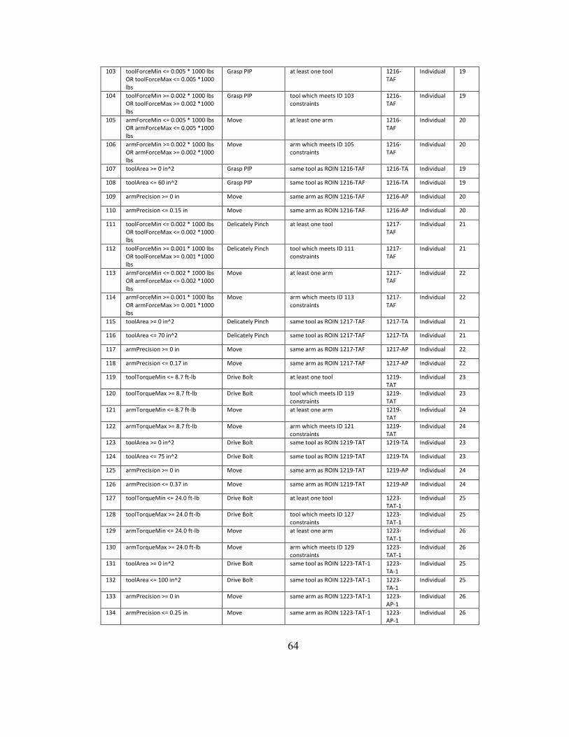
64
103 toolForceMin <= 0.005 * 1000 lbs OR toolForceMax <= 0.005 *1000 lbs
Grasp PIP at least one tool 1216-TAF
Individual 19
104 toolForceMin >= 0.002 * 1000 lbs OR toolForceMax >= 0.002 *1000 lbs
Grasp PIP tool which meets ID 103 constraints
1216-TAF
Individual 19
105 armForceMin <= 0.005 * 1000 lbs OR armForceMax <= 0.005 *1000 lbs
Move at least one arm 1216-TAF
Individual 20
106 armForceMin >= 0.002 * 1000 lbs OR armForceMax >= 0.002 *1000 lbs
Move arm which meets ID 105 constraints
1216-TAF
Individual 20
107 toolArea >= 0 in^2 Grasp PIP same tool as ROIN 1216-TAF 1216-TA Individual 19
108 toolArea <= 60 in^2 Grasp PIP same tool as ROIN 1216-TAF 1216-TA Individual 19
109 armPrecision >= 0 in Move same arm as ROIN 1216-TAF 1216-AP Individual 20
110 armPrecision <= 0.15 in Move same arm as ROIN 1216-TAF 1216-AP Individual 20
111 toolForceMin <= 0.002 * 1000 lbs OR toolForceMax <= 0.002 *1000 lbs
Delicately Pinch at least one tool 1217-TAF
Individual 21
112 toolForceMin >= 0.001 * 1000 lbs OR toolForceMax >= 0.001 *1000 lbs
Delicately Pinch tool which meets ID 111 constraints
1217-TAF
Individual 21
113 armForceMin <= 0.002 * 1000 lbs OR armForceMax <= 0.002 *1000 lbs
Move at least one arm 1217-TAF
Individual 22
114 armForceMin >= 0.001 * 1000 lbs OR armForceMax >= 0.001 *1000 lbs
Move arm which meets ID 113 constraints
1217-TAF
Individual 22
115 toolArea >= 0 in^2 Delicately Pinch same tool as ROIN 1217-TAF 1217-TA Individual 21
116 toolArea <= 70 in^2 Delicately Pinch same tool as ROIN 1217-TAF 1217-TA Individual 21
117 armPrecision >= 0 in Move same arm as ROIN 1217-TAF 1217-AP Individual 22
118 armPrecision <= 0.17 in Move same arm as ROIN 1217-TAF 1217-AP Individual 22
119 toolTorqueMin <= 8.7 ft-lb Drive Bolt at least one tool 1219-TAT
Individual 23
120 toolTorqueMax >= 8.7 ft-lb Drive Bolt tool which meets ID 119 constraints
1219-TAT
Individual 23
121 armTorqueMin <= 8.7 ft-lb Move at least one arm 1219-TAT
Individual 24
122 armTorqueMax >= 8.7 ft-lb Move arm which meets ID 121 constraints
1219-TAT
Individual 24
123 toolArea >= 0 in^2 Drive Bolt same tool as ROIN 1219-TAT 1219-TA Individual 23
124 toolArea <= 75 in^2 Drive Bolt same tool as ROIN 1219-TAT 1219-TA Individual 23
125 armPrecision >= 0 in Move same arm as ROIN 1219-TAT 1219-AP Individual 24
126 armPrecision <= 0.37 in Move same arm as ROIN 1219-TAT 1219-AP Individual 24
127 toolTorqueMin <= 24.0 ft-lb Drive Bolt at least one tool 1223-TAT-1
Individual 25
128 toolTorqueMax >= 24.0 ft-lb Drive Bolt tool which meets ID 127 constraints
1223-TAT-1
Individual 25
129 armTorqueMin <= 24.0 ft-lb Move at least one arm 1223-TAT-1
Individual 26
130 armTorqueMax >= 24.0 ft-lb Move arm which meets ID 129 constraints
1223-TAT-1
Individual 26
131 toolArea >= 0 in^2 Drive Bolt same tool as ROIN 1223-TAT-1 1223-TA-1
Individual 25
132 toolArea <= 100 in^2 Drive Bolt same tool as ROIN 1223-TAT-1 1223-TA-1
Individual 25
133 armPrecision >= 0 in Move same arm as ROIN 1223-TAT-1 1223-AP-1
Individual 26
134 armPrecision <= 0.25 in Move same arm as ROIN 1223-TAT-1 1223-AP-1
Individual 26

65
135 toolForceMin <= .75 * 1000 lbs OR toolForceMax <=.75 *1000 lbs
Grip Small Object at least one tool different than ROIN 1223-1
1223-TAF-2
Individual 27
136 toolForceMin >= -.75 * 1000 lbs OR toolForceMax >= -.75 *1000 lbs
Grip Small Object tool which meets ID 135 constraints
1223-TAF-2
Individual 27
137 armForceMin <= .75 * 1000 lbs OR armForceMax <=.75 *1000 lbs
Move at least one arm different than ROIN 1223-1
1223-TAF-2
Individual 28
138 armForceMin >= -.75 * 1000 lbs OR armForceMax >= -.75 *1000 lbs
Move arm which meets ID 137 constraints
1223-TAF-2
Individual 28
139 toolArea >= 0 in^2 Grip Small Object same tool as ROIN 1223-TAF-2 1223-TA-2
Individual 27
140 toolArea <= 100 in^2 Grip Small Object same tool as ROIN 1223-TAF-2 1223-TA-2
Individual 27
141 armPrecision >= 0 in Move same arm as ROIN 1223-TAF-2 1223-AP-2
Individual 28
142 armPrecision <= 0.50 in Move same arm as ROIN 1223-TAF-2 1223-AP-2
Individual 28
143 toolLength + armLength >= 25 ft Grip Small Object + Move
tool and arm which meet ROIN 1226-1 constraints
1224-TAL
Compound 29,30
144 toolLength + armLength <= 35 ft Grip Small Object + Move
tool and arm which meet ID 143 constraints
1224-TAL
Compound 29,30
145 toolLength + armLength >= 25 ft Grip Small Object + Move
tool and arm which meet ROIN 1226-2 constraints
1224-TAL
Compound 31,32
146 toolLength + armLength <= 35 ft Grip Small Object + Move
tool and arm which meet ID 145 constraints
1224-TAL
Compound 31,32
147 toolForceMin <= 1.5 * 1000 lbs OR toolForceMax <= 1.5 *1000 lbs
Grip Small Object at least one tool 1226-TAF-1
Individual 29
148 toolForceMin >= .5 * 1000 lbs OR toolForceMax >= .5 *1000 lbs
Grip Small Object tool which meets ID 147 constraints
1226-TAF-1
Individual 29
149 armForceMin <= 1.5 * 1000 lbs OR armForceMax <= 1.5 *1000 lbs
Move at least one arm 1226-TAF-1
Individual 30
150 armForceMin >= .5 * 1000 lbs OR armForceMax >= .5 *1000 lbs
Move arm which meets ID 149 constraints
1226-TAF-1
Individual 30
151 toolArea >= 0 in^2 Grip Small Object same tool as ROIN 1226-TAF-1 1226-TA-1
Individual 29
152 toolArea <= 140 in^2 Grip Small Object same tool as ROIN 1226-TAF-1 1226-TA-1
Individual 29
153 armPrecision >= 0 in Move same arm as ROIN 1226-TAF-1 1226-AP-1
Individual 30
154 armPrecision <= 0.20 in Move same arm as ROIN 1226-TAF-1 1226-AP-1
Individual 30
155 toolForceMin <= 1.5 * 1000 lbs OR toolForceMax <= 1.5 *1000 lbs
Grip Small Object at least one tool different than ROIN 1226-1
1226-TAF-2
Individual 31
156 toolForceMin >= 0.5 * 1000 lbs OR toolForceMax >= 0.5 *1000 lbs
Grip Small Object tool which meets ID 155 constraints
1226-TAF-2
Individual 31
157 armForceMin <= 1.5 * 1000 lbs OR armForceMax <= 1.5 *1000 lbs
Move at least one arm different than ROIN 1226-1
1226-TAF-2
Individual 32
158 armForceMin >= 0.5 * 1000 lbs OR armForceMax >= 0.5 *1000 lbs
Move arm which meets ID 157 constraints
1226-TAF-2
Individual 32
159 toolArea >= 0 in^2 Grip Small Object same tool as ROIN 1226-TAF-2 1226-TA-2
Individual 31
160 toolArea <= 140 in^2 Grip Small Object same tool as ROIN 1226-TAF-2 1226-TA-2
Individual 31
161 armPrecision >= 0 in Move same arm as ROIN 1226-TAF-2 1226-AP-2
Individual 32
162 armPrecision <= 0.20 in Move same arm as ROIN 1226-TAF-2 1226-AP-2
Individual 32

66
Appendix E: Viable Solutions After Down Selection
232.0,42.0,16.0,19935612,[A2, A2, BD11, BD7, MT1, P3, SH10, SH20, SH20] 233.0,43.0,16.5,20076732,[A2, A2, BD11, BD7, MT1, P4, SH10, SH20, SH20] 234.0,43.0,15.0,14845248,[A2, A2, BD11, BD9, MT1, P3, SH10, SH20, SH20] 234.0,44.0,17.0,20217852,[A2, A2, BD11, BD7, MT1, P5, SH10, SH20, SH20] 235.0,44.0,15.5,14986368,[A2, A2, BD11, BD9, MT1, P4, SH10, SH20, SH20] 236.0,45.0,16.0,15127488,[A2, A2, BD11, BD9, MT1, P5, SH10, SH20, SH20] 241.0,48.0,18.5,111381372,[A2, A2, BD11, BD7, MT1, P3, SH10, SH20, SH33] 242.0,49.0,19.0,111522492,[A2, A2, BD11, BD7, MT1, P4, SH10, SH20, SH33] 243.0,45.0,18.5,19935598,[A2, A2, BD11, BD5, BD7, MT1, P3, SH10, SH20, SH20] 243.0,46.0,17.5,202827132,[A2, A2, BD11, BD7, MT1, P3, SH10, SH20, SH35] 243.0,49.0,17.5,106291008,[A2, A2, BD11, BD9, MT1, P3, SH10, SH20, SH33] 243.0,50.0,19.5,111663612,[A2, A2, BD11, BD7, MT1, P5, SH10, SH20, SH33] 244.0,46.0,19.0,20076718,[A2, A2, BD11, BD5, BD7, MT1, P4, SH10, SH20, SH20] 244.0,47.0,18.0,202968252,[A2, A2, BD11, BD7, MT1, P4, SH10, SH20, SH35] 244.0,50.0,18.0,106432128,[A2, A2, BD11, BD9, MT1, P4, SH10, SH20, SH33] 245.0,44.0,16.5,14845212,[A2, A2, BD11, BD7, BD9, MT1, P3, SH10, SH20, SH20] 245.0,46.0,17.5,14845234,[A2, A2, BD11, BD5, BD9, MT1, P3, SH10, SH20, SH20] 245.0,47.0,16.5,197736768,[A2, A2, BD11, BD9, MT1, P3, SH10, SH20, SH35] 245.0,47.0,19.5,19935584,[A2, A2, BD11, BD3, BD7, MT1, P3, SH10, SH20, SH20] 245.0,48.0,18.5,203109372,[A2, A2, BD11, BD7, MT1, P5, SH10, SH20, SH35] 245.0,51.0,18.5,106573248,[A2, A2, BD11, BD9, MT1, P5, SH10, SH20, SH33] 246.0,45.0,17.0,14986332,[A2, A2, BD11, BD7, BD9, MT1, P4, SH10, SH20, SH20] 246.0,47.0,18.0,14986354,[A2, A2, BD11, BD5, BD9, MT1, P4, SH10, SH20, SH20] 246.0,48.0,17.0,197877888,[A2, A2, BD11, BD9, MT1, P4, SH10, SH20, SH35] 246.0,48.0,20.0,20076704,[A2, A2, BD11, BD3, BD7, MT1, P4, SH10, SH20, SH20] 247.0,46.0,17.5,15127452,[A2, A2, BD11, BD7, BD9, MT1, P5, SH10, SH20, SH20] 247.0,48.0,18.5,14845220,[A2, A2, BD11, BD3, BD9, MT1, P3, SH10, SH20, SH20] 247.0,49.0,17.5,198019008,[A2, A2, BD11, BD9, MT1, P5, SH10, SH20, SH35] 247.0,49.0,20.5,20217824,[A2, A2, BD11, BD3, BD7, MT1, P5, SH10, SH20, SH20] 248.0,49.0,19.0,14986340,[A2, A2, BD11, BD3, BD9, MT1, P4, SH10, SH20, SH20] 249.0,50.0,19.5,15127460,[A2, A2, BD11, BD3, BD9, MT1, P5, SH10, SH20, SH20] 250.0,54.0,21.0,141863292,[A2, A2, BD11, BD7, MT1, P3, SH10, SH33, SH33] 251.0,55.0,21.5,142004412,[A2, A2, BD11, BD7, MT1, P4, SH10, SH33, SH33] 252.0,51.0,21.0,111381358,[A2, A2, BD11, BD5, BD7, MT1, P3, SH10, SH20, SH33] 252.0,52.0,20.0,172345212,[A2, A2, BD11, BD7, MT1, P3, SH10, SH33, SH35] 252.0,55.0,20.0,136772928,[A2, A2, BD11, BD9, MT1, P3, SH10, SH33, SH33] 252.0,56.0,22.0,142145532,[A2, A2, BD11, BD7, MT1, P5, SH10, SH33, SH33] 253.0,52.0,21.5,111522478,[A2, A2, BD11, BD5, BD7, MT1, P4, SH10, SH20, SH33] 253.0,53.0,20.5,172486332,[A2, A2, BD11, BD7, MT1, P4, SH10, SH33, SH35] 253.0,56.0,20.5,136914048,[A2, A2, BD11, BD9, MT1, P4, SH10, SH33, SH33] 254.0,49.0,20.0,202827118,[A2, A2, BD11, BD5, BD7, MT1, P3, SH10, SH20, SH35] 254.0,50.0,19.0,106290972,[A2, A2, BD11, BD7, BD9, MT1, P3, SH10, SH20, SH33] 254.0,52.0,20.0,106290994,[A2, A2, BD11, BD5, BD9, MT1, P3, SH10, SH20, SH33] 254.0,53.0,19.0,167254848,[A2, A2, BD11, BD9, MT1, P3, SH10, SH33, SH35] 254.0,53.0,22.0,111381344,[A2, A2, BD11, BD3, BD7, MT1, P3, SH10, SH20, SH33] 254.0,54.0,21.0,172627452,[A2, A2, BD11, BD7, MT1, P5, SH10, SH33, SH35] 254.0,57.0,21.0,137055168,[A2, A2, BD11, BD9, MT1, P5, SH10, SH33, SH33] 255.0,50.0,20.5,202968238,[A2, A2, BD11, BD5, BD7, MT1, P4, SH10, SH20, SH35] 255.0,51.0,19.5,106432092,[A2, A2, BD11, BD7, BD9, MT1, P4, SH10, SH20, SH33] 255.0,53.0,20.5,106432114,[A2, A2, BD11, BD5, BD9, MT1, P4, SH10, SH20, SH33] 255.0,54.0,19.5,167395968,[A2, A2, BD11, BD9, MT1, P4, SH10, SH33, SH35] 255.0,54.0,22.5,111522464,[A2, A2, BD11, BD3, BD7, MT1, P4, SH10, SH20, SH33] 256.0,47.0,19.0,14845198,[A2, A2, BD11, BD5, BD7, BD9, MT1, P3, SH10, SH20, SH20] 256.0,48.0,18.0,197736732,[A2, A2, BD11, BD7, BD9, MT1, P3, SH10, SH20, SH35] 256.0,48.0,19.0,19936188,[A2, A2, BD11, BD7, MT1, P3, SH10, SH20, SH20, SH8] 256.0,50.0,19.0,197736754,[A2, A2, BD11, BD5, BD9, MT1, P3, SH10, SH20, SH35] 256.0,50.0,22.0,19935586,[A2, A2, BD11, BD3, BD5, BD7, MT1, P3, SH10, SH20, SH20] 256.0,51.0,18.0,258700608,[A2, A2, BD11, BD9, MT1, P3, SH10, SH35, SH35] 256.0,51.0,21.0,202827104,[A2, A2, BD11, BD3, BD7, MT1, P3, SH10, SH20, SH35] 256.0,52.0,20.0,106573212,[A2, A2, BD11, BD7, BD9, MT1, P5, SH10, SH20, SH33] 256.0,54.0,21.0,106290980,[A2, A2, BD11, BD3, BD9, MT1, P3, SH10, SH20, SH33] 256.0,55.0,20.0,167537088,[A2, A2, BD11, BD9, MT1, P5, SH10, SH33, SH35] 256.0,55.0,23.0,111663584,[A2, A2, BD11, BD3, BD7, MT1, P5, SH10, SH20, SH33] 257.0,48.0,19.5,14986318,[A2, A2, BD11, BD5, BD7, BD9, MT1, P4, SH10, SH20, SH20] 257.0,49.0,18.5,197877852,[A2, A2, BD11, BD7, BD9, MT1, P4, SH10, SH20, SH35] 257.0,49.0,19.5,20077308,[A2, A2, BD11, BD7, MT1, P4, SH10, SH20, SH20, SH8] 257.0,51.0,19.5,197877874,[A2, A2, BD11, BD5, BD9, MT1, P4, SH10, SH20, SH35] 257.0,51.0,22.5,20076706,[A2, A2, BD11, BD3, BD5, BD7, MT1, P4, SH10, SH20, SH20] 257.0,52.0,18.5,258841728,[A2, A2, BD11, BD9, MT1, P4, SH10, SH35, SH35] 257.0,52.0,21.5,202968224,[A2, A2, BD11, BD3, BD7, MT1, P4, SH10, SH20, SH35] 257.0,55.0,21.5,106432100,[A2, A2, BD11, BD3, BD9, MT1, P4, SH10, SH20, SH33] 258.0,46.0,18.0,19935900,[A2, A2, BD11, BD7, MT1, P3, SH10, SH20, SH20, SH6] 258.0,49.0,18.0,14845824,[A2, A2, BD11, BD9, MT1, P3, SH10, SH20, SH20, SH8] 258.0,49.0,20.0,14845184,[A2, A2, BD11, BD3, BD7, BD9, MT1, P3, SH10, SH20, SH20] 258.0,50.0,19.0,198018972,[A2, A2, BD11, BD7, BD9, MT1, P5, SH10, SH20, SH35] 258.0,50.0,20.0,20218428,[A2, A2, BD11, BD7, MT1, P5, SH10, SH20, SH20, SH8] 258.0,51.0,21.0,14845222,[A2, A2, BD11, BD3, BD5, BD9, MT1, P3, SH10, SH20, SH20] 258.0,52.0,20.0,197736740,[A2, A2, BD11, BD3, BD9, MT1, P3, SH10, SH20, SH35]

67
References
[1] NASA Goddard Space Flight Center, "On-Orbit Satellite Servicing Study
Project Report," October 2010. [2] B. R. Sullivan and D. L. Akin, "A Survey of Serviceable Spacecraft Failures,"
in AIAA Space 2001 Conference and Exposition, Albuquerque, New Mexico, 2001.
[3] "Hubble Space Telescope," [Online]. Available: http://hubblesite.org/. [Accessed 2016].
[4] J. Knizhnik, M. Austin and C. Carignan, "Robotic Satellite Servicing Trade Space Down-Selection," in 27th Annual International Symposium of The International Council on Systems Engineering (INCOSE 2017), Adelaide, Australia, 2017.
[5] "Robotic Refueling Missing," [Online]. Available: https://ssco.gsfc.nasa.gov/rrm_tools.html and https://ssco.gsfc.nasa.gov/rrm_tasks.html. [Accessed 2016].
[6] N. Nassar and M. Austin, "Model-Based Systems Engineering Design and Analysis with RDF Graphs," in Conference on Systems Engineering Research, Atlanta, GA, USA, 2013.
[7] IBM, "IBM ILOG CPLEX Optimization Studio," [Online]. Available: https://www.ibm.com/us-en/marketplace/ibm-ilog-cplex. [Accessed November 2017].
[8] T. J. Bayer, M. Bennett, C. L. Delp, D. Dvorak, J. S. Jenkins and S. Mandutianu, "Update – Concept of Operations for Integrated Model-Centric Engineering at JPL," in 2011 IEEE Aerospace Conference, Big Sky, Montana, 2011.
[9] D. Kaslow, G. Soremekun, H. Kim and S. Spangelo, "Integrated Model-Based Systems Engineering (MBSE) Applied to the Simulation of a CubeSat Mission," in 2014 IEEE Aerospace Conference, Big Sky, Montana, 2014.
[10] S. Friedenthal, A. Moore and R. Steiner, A Practical Guide to SysML - The Systems Modeling Language, 3rd ed., Waltham, MA: Elsevier, Inc., 2015.
[11] P. Delgoshaei and M. A. Austin, "Framework for Knowledge-Based Fault Detection and Diagnostics in Multi-Domain Systems: Application to Heating Ventilation and Air Conditioning Systems," International Journal On Advances in Systems and Measurements, 2017.
[12] D. L. Akin, M. L. Minsky, E. D. Thiel and C. R. Kurtzman, "Space Applications of Automation, Robotics and Machine Intelligence Systems (ARAMIS) - Phase II, Volume 1: Telepresence Technology Base Development," NASA Contractor Report 3734, Massachusetts Institute of Technology, Cambridge, MA, USA, 1983.

68
[13] K. J. Pilotte, "Analysis of Grasp Requirements for Telerobotic Satellite Servicing," Master of Science Thesis, University of Maryland, College Park, MD, USA, 2004.
[14] P. Delgoshaei and M. Austin, "Software Patterns for Traceability of Requirements to Finite State Machine Behavior: Application to Rail Transit Systems Design and Management," in INCOSE International Symposium, Rome, Italy, 2012.
[15] M. Mosteller, M. Austin, S. Yang and R. Ghodssi, "Platforms for Engineering Experimental Biomedical Systems," in 22nd Annual International Symposium of the International Council on Systems Engineering (INCOSE 2012), Rome, Italy, 2012.
[16] C. Hennig, A. Viehl, B. Kampgen and H. Eisenmann, "Ontology-Based Design of Space Systems," Airbus Defence and Space, Space Systems and FZI Research Center for Information Technology, Friedrichshafen, Germany and Karlsruhe, Germany, 2011.
[17] L. Petgna, M. Austin and M. Blackburn, "Semantically-enabled Model-based Systems Engineering of Safety Critical Network of Systems," in 27th Annual International Symposium of The International Council on Systems Engineering (INCOSE 2017), Adelaide, Austrailia, 2017.
[18] P. Delgoshaei, M. Austin and A. Pertzborn, "A Semantic Framework for Modeling and Simulation of Cyber-Physical Systems," International Journal On Advances in Systems and Measurements, vol. 7, pp. 3-4, December 2014.
[19] J. Huckaby and H. I. Christensen, "A Case for SysML in Robotics," in IEEE International Conference on Automation Science and Engineering (CASE), Taipei, Taiwan, 2014.
[20] "RESTORE-L Mission," [Online]. Available: http://www.nasa.gov/feature/nasa-s-restore-l-mission-to-refuel-landsat- 7-demonstrate-crosscutting-technologies. [Accessed 2016].
[21] L. P. Skyles, "PIP Pin Reliability and Design," in The 28th Aerospace Mechanisms Symposium, Cleveland, Ohio, 1994.
[22] "Man-Systems Integration Standards," National Aeronautics and Space Administration, [Online]. Available: https://msis.jsc.nasa.gov/sections/section04.htm#_4.9_STRENGTH. [Accessed 2017].
[23] D. L. Akin, B. Roberts, K. Pilotte and M. Baker, "Robotic Augmentation of EVA for Hubble Space Telescope Servicing," in AIAA Space 2003 Conference & Exposition, Long Beach, California, 2003.
[24] M. Baker, "Robot-Assisted Servicing of the Hubble Space Telescope," in AIAA Mid-Atlantic Student Conference, College Park, MD, 2003.

69
[25] B. R. Sullivan, "Technical and Economic Feasibility of Telerobotic On-Orbit Satellite Servicing," Doctor of Philosophy Thesis, University of Maryland, College Park, Maryland, 2005.