ac 2008-185: a common design-build-test project ...faculty.rwu.edu/wpalm/research/plumley et al - a...
TRANSCRIPT

AC 2008-185: A COMMON DESIGN-BUILD-TEST PROJECT INCORPORATINGFRESHMAN AND SENIOR UNDERGRADUATE ANALYSIS SKILLS
Michael Plumley, US Coast Guard AcademyLT Michael Plumley is on active duty in the U.S. Coast Guard and is a faculty member and 1998graduate of the Mechanical Engineering program at the U.S. Coast Guard Academy where he hasserved as course coordinator for a variety of subjects including Machine Design, Heat Transfer,and Modeling and Control of Dynamic Systems. He holds Masters of Science degrees in bothMechanical Engineering and Naval Architecture and Marine Engineering from the MassachusettsInstitute of Technology and is a registered Professional Engineer in the State of Connecticut. Hisprevious assignments included service as shipboard engineer and port engineer.
William Palm, Massachusetts Institute of TechnologyWilliam J. Palm IV is a doctoral student at the Massachusetts Institute of Technology and aformer Lecturer of Mechanical Engineering at the U.S. Coast Guard Academy. He has a M.S. inMechanical Engineering from the University of California at Berkeley and a B.S.M.E. from PennState. He worked for several years as a design engineer, holds four patents, and continues toconsult for the product design industry.
William Simpson, U.S. Coast Guard AcademyDr. William M. Simpson, Jr. is a faculty member in the Engineering Department at the U.S. CoastGuard Academy. He has a Ph.D. in Aerospace Engineering form the University of Maryland, aMasters in Naval Architecture and Marine Engineering form Massachusetts Institute ofTechnology, and a Bachelor of Science from the U. S. Coast Guard Academy. He is a registeredProfessional Engineer in the State of Connecticut. He served on active duty in the U.S. CoastGuard from 1965 to 1992 and had assignments in Marine Safety, Naval Engineering, Acquisition,and Research and Development.
© American Society for Engineering Education, 2008

A COMMON DESIGN-BUILD-TEST PROJECT INCORPORATING
FRESHMAN AND SENIOR UNDERGRADUATE ANALYSIS SKILLS Introduction
In depth discussion is presented on a project created to develop student appreciation for engineering analytical skills developed during a four year Mechanical Engineering program. The unique project, which required students to lift a floating weight out of the water using a floating machine of their own design, was developed and used in a concurrently run freshman statics course and a senior machine design course. Encouragement of student interaction between seniors and freshmen was used to emphasize how much students had learned over the course of their undergraduate study. Students in each level were given a similar need statement. Advanced students were given less background information, fewer constraints, and assigned more deliverables which allowed more room for design failure. The goal was to demonstrate that designs may be constructed without significant analysis yet greater insight can be derived using analytical tools. Motivation
The motivation for this project was the observed reluctance of many students to applying analytical concepts covered in previous courses to their design projects. The authors observed students often expressing frustration over the replacement of what they considered fun, calculation free, design projects in lower level courses with calculation intensive projects in upper level classes. The earlier projects, aimed at increasing student interest in engineering, were often free of analysis requirements. Some students commented that calculations prevented flexibility and creativity. They seemed to translate this into a lack of applicability of their analytical courses to practical design, or at worst to a cruel ‘bait and switch’ on the part of academia. The goal of this project was to give students a greater appreciation for analytical tools developed in different courses. Mechanical Engineering students at the US Coast Guard Academy follow a course of study focused on the development of design and problem solving skills. Students in all majors are required to take “Statics and Engineering Design (SED)” during their first year. Mechanical Engineering students then take Introduction to Mechanical Engineering Design (IMED), which introduces open-ended problem solving and basic CAD and manufacturing skills. Sophomore and junior years are focused on analysis based courses, such as Mechanics of Materials and Thermodynamics, in preparation for those requiring integrated knowledge in their senior year, such as Experimental Methods, Machine Design, and Controls. Lab periods in the senior Machine Design course are dedicated to preparing students for their final capstone design project through participation in a common design, build, and test exercise. Machine Design projects focused on only the course at hand may help enforce a notion that classes are not integrated. Many projects at the Coast Guard Academy included need statements requiring design of small table top models using basic machine components such as gears, pulleys, belts, and chains. Unfortunately the power sources were often battery powered DC

motors which practically ensured success for designs which were not optimized. Students hesitated to create detailed objectives or complete basic calculations, instead resorting to last minute trial and error methods. Others created unnecessarily complicated designs in hopes of receiving a better grade for their creativity. While allowing opportunity for analysis and optimization, the projects did not require calculation to achieve success and may inadvertently have taught students that complicated means creative. Students expressed frustration over instructor demands to analyze components when it was obvious that such calculations were not necessary for success. Early student projects in the major typically do not require integration of concepts or much calculation. Students participate in their first design project during the first year Statics course. In the past they constructed stick bridges to understand trusses and small barges to observe basic ship stability. These projects required little calculation to be successful. Introduction to Mechanical Engineering Design includes creativity oriented projects which can not rely on analytical skills of upper level courses. This may be the source of habits which remain in later years. During the 2006-2007 academic year members of the Engineering Department at the Coast Guard Academy set out to design projects highlighting the relationship among multiple engineering disciplines while requiring analysis and creative design techniques appropriate for student knowledge levels. Both seniors and freshmen were required to design, build, and test a barge and crane device to lift a 2 pound weighted coffee can out of a body of water. The freshmen were given approximately five hours of class time with constrained dimensions, a detailed parts list, a robust 3 volt DC motor, and detailed stability equations. The seniors were given ostensibly the same problem, with considerably less guidance, and approximately 30 hours of lab time. They were given a set of constrained dimensions, a budget for parts, a rat trap for power, technical and progress report writing requirements, calculation requirements, and a scoring algorithm imposing trade-offs between size, weight, cost, and performance. The resulting projects satisfied individual course outcomes and created an opportunity to highlight the benefit of understanding basic engineering concepts. The freshman version combined the earlier truss and stability projects into a cohesive project which encouraged discussion on the relation among different disciplines. The senior project required the use of more advanced design skills practiced in earlier courses along with analytical techniques from a wide variety of courses. Senior project
Seniors worked in groups of three. A detailed memorandum given to the class at the beginning of the semester expressed the need as follows:
“A small floating barge (weighted coffee can, figure 1) given in class will be placed in still water in a small pool in the lab. You must design a barge and crane device which will lift and suspend this smaller load. You will be graded on the final height of the lowest part of the given load above the water surface two minutes after initial triggering of your device. Your sole power source will be the two torsion springs of a Victor rat trap. The springs must be wound one minute prior to triggering (in other

words you cannot wind it and let it go). Rat traps and springs may not be replaced after some time commencing 24 hours prior to the start of the competition. You will only be allowed to touch your device for up to 15 seconds during the trigger and must not do anything to disrupt the draft while triggering. The load may be attached to your device one minute prior to the start of the competition, however it must not be attached in such a way as to lift it out of the water or alter your ‘unattached’ freeboard. All components should of course be designed and sized to allow for an acceptable safety factor. If such a factor is incalculable or does not exist a reasonable testing strategy should be carried out to ensure safety. The final device and all 3D models must fit within a cubic volume of the following dimensions: 16” X 36” X 24”. Each team must requisition each part and track spending. Each team has a budget of $50 for parts outside of those not already in stock.”
Figure 1: Weighted coffee can
Students were given a two page list of required calculations and instructed to complete those applicable to their design. In this way students were free to investigate those areas which they deemed most appropriate. The open-ended problem statement required calculation and optimization of their device based on concepts from earlier courses including Statics, Dynamics, Fluids, Introduction to Mechanical Engineering Design, Mechanisms, Physics, Electrical Circuits and Machines, Mechanics of Materials, Material Science, Experimental Methods, Controls, Machine Design, and various management courses. Particularly unique aspects of the need statement are the manner in which the final can height will be measured and the restriction on dimensions. Stating dimensions without identifying the respective orientation created an immediate need to consider stability and energy conservation. To obtain accurate height estimates teams must balance the relationship between spring potential, buoyancy, and vessel heel and trim characteristics. In one instance an overly presumptuous team unnecessarily reduced their potential lift height by choosing the larger of the allowable dimensions for the length and width of the barge. During the semester students were challenged to optimize their barge design with respect to trade offs. This was encouraged by assigning a portion of the grade to performance in two competitions. These were run two weeks apart to allow time for improvement based on lessons learned. The competitions were governed by the scoring algorithm that follows. The “highest” and “lowest” values obtained among the entries for each category were used to normalize
Dmean=4.0 IN Height = 5.4375 IN

parameters. Parameters included: the total weight of the barge; the weight of the insulation foam used for the hull; the “highest total cost” which consisted of all materials used whether purchased or on hand; the “non stock cost” which consisted of materials purchased using lab funds; “lift height” which was the height of can bottom above water surface after lift; and “height estimate – achieved height” which was a comparison of the teams analytically determined results to actual competition results. Three parameters determined by the judges were “wet deck”, “capsize”, and “major rule violation”. These last parameters were included to address particularly unacceptable performance.
* + * + * +violationrulemajorcapsizedeckwet
heightacheivedestimateheightHighestheightacheivedestimateheightLowest
heightacheivedestimateheightHighestheightacheivedestimateheightgroup
heightliftLowestheightliftHighest
heightliftLowestheightliftgroup
tnonstockHightesttnonstockLowest
tnonstockHighesttnonstockgroup
ttotalHightestttotalLowest
ttotalHighestttotalgroup
weightfoamHightestweightfoamLowest
weightfoamHighestweightfoamgroup
weightHightestweightLowest
weightHighestweightgroupSCORE
5.05.03.0
||||
||||1.0
4.0
cos''cos''
cos''cos''1.0
coscos
coscos1.0
1.02.0
///
ÕÕÖ
ÔÄÄÅ
Ã//////
-
ÕÕÖ
ÔÄÄÅ
Ã//
-
ÕÕÖ
ÔÄÄÅ
Ã//
-ÕÕÖ
ÔÄÄÅ
Ã//
-
ÕÕÖ
ÔÄÄÅ
Ã//
-ÕÕÖ
ÔÄÄÅ
Ã//
?
(1)
Written assignments included weekly progress memos and four formal reports. Teams were required to present their official height estimate in the second formal report for use in future competition scoring. This was required prior to construction to reward accurate analysis. Design groups gave three presentations during the semester including a preliminary design review, a presentation to freshmen, and a final presentation to peers and faculty. The author observed many freshmen asking insightful questions, based in large part on their newly gained knowledge developed while working on their own project. Freshman project
Freshmen in groups of three were given a similar can and dimensions. The need statement and assignment handout were more detailed with greater guidance and constraints to ensure reasonable success. They benefited from a challenging exercise for their skill level and a greater understanding of the technical presentations offered by advanced students later in the semester. Less emphasis was placed on presentation and project management skills, although a written report was required. Analysis was restricted to those techniques developed in the Statics course. To ensure freshmen could design an effective device, direction was given on allowable materials and dimensions. An initial need statement was given and an example barge was presented:
“Working in groups of 3, design and construct a crane barge that will lift a can buoy. Using the rigid foam block provided, you will design and construct a free standing crane/boom that will enable you to lift the weighted can using a string hoist driven by a DC electric motor powered by a single AA battery. The crane/boom is to be a truss structure built using craft (popsicle) sticks. The concept is shown in the sketch

below. The DC motor is a high RPM, low torque devise so some combination of speed reduction and pulleys will be required to lift the 2.3 lb can out of the water. It may be necessary to add ballast to increase both longitudinal and transverse stability in order to lift the can.”
Figure 2: Example barge and truss design
Figure 3: Barge motor and transmission
with 10 tooth and 48 tooth sprockets.
The freshmen were given equations to calculate buoyancy and component weight. They were also given hints on how to construct frames and gear trains. To assist with truss calculations, in light of the fact that students have not had a mechanics of materials course, empirical estimates were given for truss element strength. Students were instructed to size truss members using table 1, shown below. Element size is based on how many sticks are glued side by side.

Table 1: Barge truss structural elements, allowable loading.
Max. tension
capacity
Maximum compression capacity (lb)
Length of Member
Element size
max load (lb)
Elem. Size
1 in 2 in 3 in 4 in 5 in 6 in
1 70 1 70 70 33 19 12 8
2 140 2 140 140 133 75 48 33
3 210 3 210 210 210 169 108 75
4 280 4 280 280 280 280 243 168
5 350 5 350 350 350 350 350 350
6 420 6 420 420 420 420 420 420
Stability information was given in the project handout. Unlike seniors, who were required to research stability fundamentals, freshmen were given a constrained geometry and a set of derived equations. The sketch below illustrates the dimensions required for stability calculation using the given equations.
Figure 4 Barge and truss dimensions for derived stability equations.
Students used the following equations to determine the longitudinal center of gravity (LCG) and total weight. Figure 5, derived by the faculty, could then be used to ensure longitudinal stability.
* +Total
BallastFoamWinchBoomPulleysCan
W
xwxFoamwxwxwxwwLCG
4321 -----/? (2)
BallastFoamWinchBoomPulleysCanTotal wwwwwwW -----? (3)

SED Design Project
Fall 2006
LCG vs. weight
0.00
5.00
10.00
15.00
20.00
25.00
5 10 15 20 25 30 35
weight, lb
LC
G,
in.
fro
m c
ran
e e
nd
Unsatisfactory
Satisfactory
Unsatisfactory
Figure 5: Safe LCG vs Weight characteristics for barge and truss system.
To ensure transverse stability students were given equations to compute the vertical center of gravity (VCG), average draft (TAvg), height of transverse metacenter (KM), and metacentric height (GM).
* +Total
BallastFoamWinchBoomPulleysCan
W
4ywyFoamw3yw2yw1ywwVCG
-----/? (4)
ÕÖÔ
ÄÅÃÕÖÔ
ÄÅÃ
·?
4.62
1728
2410
WTAvg (5)
* +Avg
Avg
T
TKM
·-?
12
10
2
2
(6)
VCGKMGM /? (7)
Freshmen participated in competitions to determine which barges could handle a 5.0 lb proof load, which could lift the can the highest, and which truss could withstand the greatest load prior to failure. The latter test was optional but clearly a crowd favorite. The freshmen barges were all successful and achieved lift heights from 8.5 IN to 22.0 IN. Senior project background calculations
The nature of the senior project required students to complete calculations as part of background research. Immediate focus must be given to stability concerns, and students must reconcile the trade off between height and stability. Prudent groups made initial height estimates based on available energy and used these for initial calculations. Since a detailed description of all

calculations is beyond the scope of this paper, focus will be given on the applicable spring calculations. To calculate the available spring energy, the spring stiffness “k”, and angle to which it will be wound “し”, must be known. Students found these analytically and experimentally and compared results. Spring stiffness can be calculated using theoretical calculations presented by Shigley and Mischke1.
a
calculatedDN
Edk
8.10)2(
4
r? (8)
DNN ta r3
21 AA --? (9)
The following values were used to obtain the results given here. The elastic modulus and ultimate strength were assumed to be those of carbon steel and music wire respectively. Given the high degree of uncertainty introduced by these factors that of the dimension measurements is not reported.
Table 2 Measured and assumed spring values
D 0.369 in E 30.00 Mpsi
d 0.071 in Na 11.45
Nt 11 kcalc 1.30 lbin/rad
Assuming the arms of the spring do not contribute to the spring constant and Na=Nt a spring constant, kcalc, of 2.93 lbin/rad was computed per spring. Using a fish scale, or simple lab masses, the torque required to hold the spring at different deflections may be determined and plotted. One such plot developed by students is shown below. The resulting theoretical stiffness is 4.68 lbin/rad for both springs on the trap. This suggests the analytical result overestimates the stiffness by as much as 20%.
Rat Trap Spring Deflection vs Torque Applied
y = 4.6763x + 6.0636
0
2
4
6
8
10
12
14
16
0 0.2 0.4 0.6 0.8 1 1.2 1.4 1.6 1.8
Deflection From Preload Position (rad)
To
rqu
e (
inlb
)
Figure 6 Experimental results to determine rat trap spring stiffness
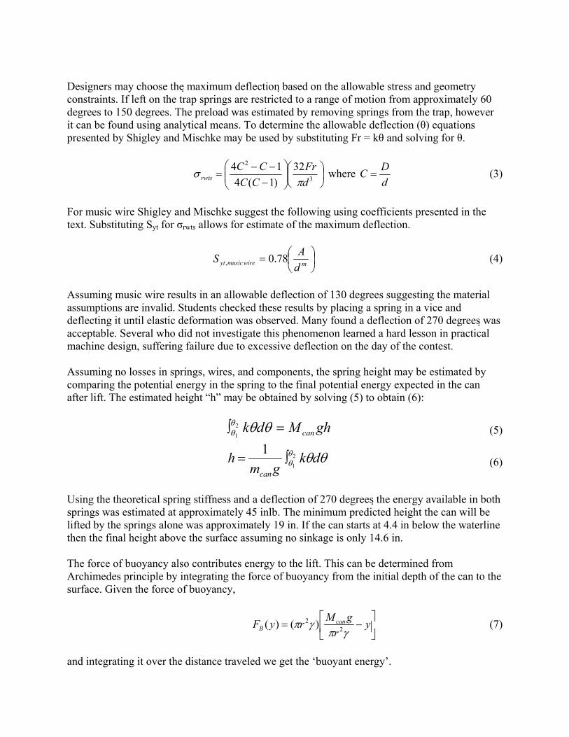
Designers may choose the 伊maximum deflection 伊based on the allowable stress and geometry constraints. If left on the trap springs are restricted to a range of motion from approximately 60 degrees to 150 degrees. The preload was estimated by removing springs from the trap, however it can be found using analytical means. To determine the allowable deflection (し) equations presented by Shigley and Mischke may be used by substituting Fr = kし and solving for し.
ÕÖÔ
ÄÅÃÕÕÖ
ÔÄÄÅ
Ã///
?3
2 32
)1(4
14
d
Fr
CC
CCrwts r
u where d
DC ? (3)
For music wire Shigley and Mischke suggest the following using coefficients presented in the text. Substituting Syt for jrwts allows for estimate of the maximum deflection.
ÕÖÔ
ÄÅÃ?
mwiremusicytd
AS 78.0, (4)
Assuming music wire results in an allowable deflection of 130 degrees suggesting the material assumptions are invalid. Students checked these results by placing a spring in a vice and deflecting it until elastic deformation was observed. Many found a deflection of 270 degrees 伊was acceptable. Several who did not investigate this phenomenon learned a hard lesson in practical machine design, suffering failure due to excessive deflection on the day of the contest. Assuming no losses in springs, wires, and components, the spring height may be estimated by comparing the potential energy in the spring to the final potential energy expected in the can after lift. The estimated height “h” may be obtained by solving (5) to obtain (6):
ghMdk can?Ð ssss
2
1 (5)
ssss dk
gmh
can
2
1
1Ð? (6)
Using the theoretical spring stiffness and a deflection of 270 degrees 伊the energy available in both springs was estimated at approximately 45 inlb. The minimum predicted height the can will be lifted by the springs alone was approximately 19 in. If the can starts at 4.4 in below the waterline then the final height above the surface assuming no sinkage is only 14.6 in. The force of buoyancy also contributes energy to the lift. This can be determined from Archimedes principle by integrating the force of buoyancy from the initial depth of the can to the surface. Given the force of buoyancy,
ÙÚ
×ÈÉ
Ç/? y
r
gMryF can
B irir
2
2 )()( (7)
and integrating it over the distance traveled we get the ‘buoyant energy’.

Ð ÙÚ
×ÈÉ
Ç/?
b
canB dyy
r
gMrE
0
2
2 )(ir
ir (8)
Assuming the can has a 4.0 in diameter and weighs 2.0 lb the final height estimate assuming the barge does not sink is 21.8 in. Through iterative calculation groups can estimate a reasonable boom height, complete stability calculations, determine barge sinkage, and refine the final height estimate. Changes in barge draft during lift can be significant. Results
The 10 senior design teams produced a diverse prototype fleet. The most successful were eccentric cam designs allowing optimal use of the varying spring torque. A photo of the winning design is shown. It used a lightweight cam machined from acrylic.
Figure 7 Winning senior design.
Another design utilizing a ratchet and pawl brake mechanism is shown below. This device incorporated a catamaran for increased stability with reduced foam volume.

Figure 8 A unique senior design. Teams were given only one run per competition making adherence to the rules and use of robust designs crucial. Lift heights for the first competition ranged from -4.5 in, for barges which failed to lift the can at all, to 22.5 in. During the second competition the range was -4.5 in to 14.5 in. High lift heights correlated strongly with a lack of rule violation suggesting teams which paid attention to detail also had the most efficient designs. It is worth noting that every team lifted the can out of the water in at least one competition. Differences in actual and predicted heights ranged from 1 in to 23 in indicating the challenge of estimating this parameter accurately given the potential for equipment failure. Reflections
Seniors initially expressed a concern that their project was ‘the same as’ that of the freshmen, yet they quickly realized the greater level of detail and effort required. Within the first week all senior groups set to the task of developing objectives consistent with the requirements. Since basic stability calculations and spring energy concepts were covered in previous courses seniors were immediately able to apply their analytical techniques from prior courses. Many groups focused on unique barge geometries requiring further research. Others focused on practical experimentation with springs to verify analytical results. By providing a scoring algorithm which did not reward or punish complexity groups were free to explore robust and effective concepts and still meet objectives being assessed for grading. Student feedback indicated this project was particularly useful in developing an understanding of stability, dynamics, and machine design concepts. Each group was required to derive the differential equations governing the motion of their respective device, and several developed Simulink models to assist in the solution of the resulting nonlinear differential equations. This provided an opportunity to relate the project to the Controls course which was taught concurrently with Machine Design. The author observed that groups who presented to freshmen expressed a greater appreciation for the benefits of the project than those who did not. Feedback from students who were not involved with freshmen indicated they felt the project was “contrived” and “like the freshman project”. Groups who took questions on their findings from freshmen expressed a greater degree of enthusiasm and appreciation for the complexities of the problem.

During the competitions the designs which prevailed were those from groups which demonstrated a greater level of engineering insight with respect to calculation and the design process. The scoring algorithm seemed to successfully reward those who correctly applied analytical tools. The best designs used eccentric cams to optimize the use of spring energy. The least successful designs were those which gave little consideration to mechanical advantage or the opportunity to wind the springs further by disassembling the trap. When asked which designs were the simplest most students identified those with the most sophisticated analysis and attention to project detail. Hence the most successful and elegant designs were also identified as the most simple. Voluntary feedback requested three months after the course ended indicated in a mix of reactions. Not all were positive. Some seniors felt the project was contrived and recommended developing a project with greater real world appeal. Several expressed that the project helped them realize the depth of what they learned. One student commented: “what Machine Design did for me was tie together all of the things that I had learned in previous classes such as SED, Strengths, Mat Sci, and Dynamics. It proved to me that I am prepared to be a Mechanical Engineer after attending the Coast Guard Academy”. Another commented the many other courses taken as a mechanical engineer “all seemed to come together in [Machine Design]”. One student noted, “I referred to my Strengths notes a lot and understood the value of that class a lot more because Machine Design pulled together a lot of components one would use in the real world”. Most comments identified that the project and course helped them the most with recalling Strengths of Materials, Statics, and Dynamics concepts. It is worth noting that 66% of the students who took this course took the FE exam in the following spring and all passed. Many commented to the author that the rigorous review of subjects during the Machine Design course helped them a great deal when preparing for the exam. 1 Shigley and Mischke. Mechanical Engineering Design. 5th ed. McGraw Hill. 1989.