ac and pulse double metallized polypropylene film ... · mmkp 383 vishay bccomponents ac and pulse...
TRANSCRIPT

Document Number: 28124 For technical questions, contact: [email protected] www.vishay.comRevision: 19-Mar-13 187
AC and Pulse Double Metallized Polypropylene Film Capacitors MMKP Radial Potted Type
MMKP 383Vishay BCcomponents
This document is subject to change without notice.THE PRODUCTS DESCRIBED HEREIN AND THIS DOCUMENT ARE SUBJECT TO SPECIFIC DISCLAIMERS, SET FORTH AT www.vishay.com/doc?91000
Not Recommended for New Design, Use New MMKP383
APPLICATIONS
Where steep pulses occur e.g. SMPS (switch mode powersupplies). Electronic lighting e.g. Ballast. Motor controlcircuits. S-correction. For flyback applications please use1400 V series.
REFERENCE SPECIFICATIONS
IEC 60384-17
MARKING
C-value; tolerance; rated voltage; sub-class; manufacturer’stype; code for dielectric material; code for factory of origin;manufacturer; year and week of manufacture
DIELECTRIC
Polypropylene film
ELECTRODES
Metallized
ENCAPSULATION
Flame retardant plastic case and epoxy resin
CONSTRUCTION
Internal serial construction
RATED (DC) VOLTAGE
250 V, 400 V, 630 V, 1000 V, 1400 V, 1600 V, 2000 V,2500 V
RATED (AC) VOLTAGE
125 V, 200 V, 220 V, 350 V, 500 V, 550 V, 700 V, 900 V
RATED PEAK-TO-PEAK VOLTAGE
350 V, 560 V, 630 V, 1000 V, 1400 V, 1600 V, 2000 V,2500 V
FEATURES
7.5 mm bent back pitch. 15 mm to 27.5 mm leadpitch. Low contact resistance. Low loss dielectric.Small dimensions for high density packaging.Supplied loose in box and taped on reel
Material categorization: For definitions of compliance please see www.vishay.com/doc?99912
ENCAPSULATION
Plastic case, epoxy resin sealed, flame retardantUL-class 94 V-0
CLIMATIC CATEGORY
55/105/56
CAPACITANCE RANGE (E24 SERIES)
0.001 µF to 2.7 µF
CAPACITANCE TOLERANCE
± 5 %
LEADS
Tinned wire
RATED (DC) TEMPERATURE
85 °C
RATED (AC) TEMPERATURE
105 °C
MAXIMUM APPLICATION TEMPERATURE
105 C
DETAIL SPECIFICATION
For more detailed data and test requirements contact:[email protected]
168x12(halfpage)168x12(halfpage)w
¯dt
l
P
h
lt
l
h h'
w
¯dtHF10
F'(1)
15
Dimensions in mm(1) F - F’ 0.3 mm
F = 7.5 + 0.6/- 0.1 mm

MMKP 383Vishay BCcomponents AC and Pulse Double Metallized Polypropylene
Film Capacitors MMKP Radial Potted Type
www.vishay.com For technical questions, contact: [email protected] Document Number: 28124188 Revision: 19-Mar-13
This document is subject to change without notice.THE PRODUCTS DESCRIBED HEREIN AND THIS DOCUMENT ARE SUBJECT TO SPECIFIC DISCLAIMERS, SET FORTH AT www.vishay.com/doc?91000
Not Recommended for New Design, Use New MMKP383
COMPOSITION OF CATALOG NUMBER
Note(1) For detailed tape specifications refer to “Packaging Information” www. vishay.com/doc?28139 or end of catalog
SPECIFIC REFERENCE DATA (250 Vdc)
(1) Old ordering code
BFC2 383 XX YY Y2222 (1) 383 XX YY Y
TYPE AND PITCHES
383
15.0 mm/7.5 mm
15.0 mm
22.5 mm
27.5 mm
TYPE PACKAGING LEAD CONFIGURATIONPREFERRED TYPES
C-TOL. 250 V 400 V 630 V 1000 V 1400 V 1600 V 2000 V 2500 V
383
Loose in box Lead length 3.5 mm ± 0.3 mm ± 5 % 00 10 20 30 40 50 60 70Taped on reel(bent back to 7.5 mm) (1)
H 16.0 mm; P0 15.0 mmreel diameter 500 mm ±5 %
03 13 23 33 43 53 63 -
Dimensions of this code numbers stay between brackets
ON REQUEST
383
Loose in boxLead length 5.0 mm ± 1.0 mm ±5 % 01 11 21 31 41 51 61 71Lead length 25.0 mm ± 2.0 mm ±5 % 04 14 24 34 44 54 64 74
Taped on reel (1) H 18.5 mm; P0 12.7 mm ±5 % 02 12 22 32 42 52 62 72
Taped on reel(bent back to 7.5 mm) (1)
H 16.0 mm; P0 15.0 mmreel diameter 356 mm ±5 %
05 15 25 35 45 55 65 -
Dimensions of this code numbers stay between brackets
Taped on reel(bent back to 10.0 mm) (1)
H 16.0 mm; P0 15.0 mmreel diameter 500 mm ±5 % 08 18 28 38 48 58 68 -
MULTIPLIER(nF)
0.1 2
1 3
10 4
100 5
CAPACITANCE(numerically)
Example:
104 10 x 10 100 nF
DESCRIPTION VALUETangent of loss angle: at 10 kHz at 100 kHzC 0.15 µF 5 x 10⁻⁴ 20 x 10-4
0.15 µF C 0.39 µF 5 x 10⁻⁴ 25 x 10-4
0.39 µF C 0.56 µF 10 x 10-4 25 x 10-4
0.56 µF C 0.82 µF 10 x 10-4 40 x 10-4
0.82 µF C 1.2 µF 10 x 10-4 50 x 10-4
1.2 µF C 1.8 µF 10 x 10-4 65 x 10-4
1.8 µF C 2.2 µF 15 x 10-4 75 x 10-4
2.2 µF C 2.7 µF 15 x 10-4 85 x 10-4
Rated voltage pulse slope (dU/dt)R:C 0.15 µF 450 V/µs0.15 µF C 0.39 µF 900 V/µs0.39 µF C 0.82 µF 290 V/µs0.82 µF C 2 µF 190 V/µs2 µF C 2.7 µF 130 V/µsR between leads, for C 1 µF at 100 V, 1 min 100 000 MRC between leads, for C 1 µF at 100 V, 1 min 100 000 sR between leads and case, 100 V, 1 min 30 000 MIonization (AC) voltage (typical value) at 50 pC peak discharge 220 VWithstanding (DC) voltage (cut off current 10 mA), rise time 100 V/s 400 V, 1 minWithstanding (DC) voltage between leads and case 2840 V, 1 minMaximum application temperature 105 °C

Document Number: 28124 For technical questions, contact: [email protected] www.vishay.comRevision: 19-Mar-13 189
MMKP 383AC and Pulse Double Metallized Polypropylene
Film Capacitors MMKP Radial Potted TypeVishay BCcomponents
This document is subject to change without notice.THE PRODUCTS DESCRIBED HEREIN AND THIS DOCUMENT ARE SUBJECT TO SPECIFIC DISCLAIMERS, SET FORTH AT www.vishay.com/doc?91000
Not Recommended for New Design, Use New MMKP383
URdc = 250 V; URac = 125 V; Upp = 350 V; C-tol. = ± 5 %
Notes(1) Net weight for short lead products only• SPQ = Standard Packaging Quantity
URdc = 250 V; URac = 125 V; Upp = 350 V; C-tol. = ± 5 %
Notes(1) Net weight for short lead products only• SPQ = Standard Packaging Quantity
C(µF)
DIMENSIONSw x h (h’) x l
(mm)
MASS(g) (1)
CATALOG NUMBER BFC2 383 XXYYY AND PACKAGINGLOOSE IN BOX REEL C-VALUE
Leads 3.5 ± 0.3 mm
Leads 25.0 ± 2.0 mm Original pitch Pitch = 7.5 mm (bent back)
..YYYØ 500 mm Ø 356 mmXX
(SPQ)XX
(SPQ)XX
(SPQ)XX
(SPQ)XX
(SPQ)
Pitch = 15 mm ± 0.4 mm; dt = 0.80 mm ± 0.08 mm Pitch = 15 mm Pitch = 7.5 mm (bent back)0.082
5.0 x 11.0 (13.0) x 17.5 1.100…
(1250) 04…
(1000) 02…
(1100) 03…(950)
05…(550)
8230.091 9130.1 1040.11
6.0 x 12.0 (14.0) x 17.5 1.400…
(1000) 04…
(1000) 02… (900)
03… (800)
05… (450)
1140.12 1240.13 1340.15 1540.16
7.0 x 13.5 (15.5) x 17.5 1.800… (750)
04… (500)
02… (800)
03… (700)
05…(400)
1640.18 1840.2 2040.22
8.5 x 15.0 (17.0) x 17.5 2.600… (750)
04… (500)
02…(650)
03…(550)
05…(300)
2240.24 2440.27 2740.3 3040.33
10.0 x 16.5 (18.5) x 17.5 3.300… (500)
04… (450)
02…(600)
03…(500)
05… (250)
3340.36 3640.39 394
C(µF)
DIMENSIONSw x h x l
(mm)
MASS(g) (1)
CATALOG NUMBER BFC2 383 XXYYY AND PACKAGINGLOOSE IN BOX REEL C-VALUE
Leads 3.5 ± 0.3 mm
Leads 25.0 ± 2.0 mm
Original pitch ..YYY
XX(SPQ)
XX(SPQ)
XX(SPQ)
Pitch = 22.5 mm ± 0.4 mm; dt = 0.80 mm ± 0.08 mm Pitch = 22.5 mm
0.43 7.0 x 116.5 x 26.0 3.000… (200)
04… (250)
02… (550)
434
0.47
8.5 x 18.0 x 26.0 4.200…(200)
04… (250)
02… (450)
4740.51 5140.56 5640.62 6240.68
10.0 x 19.5 x 26.0 5.300… (200)
04… (200)
02… (350)
6840.75 7540.82 824Pitch = 27.5 mm ± 0.4 mm; dt = 0.80 mm ± 0.08 mm Pitch = 27.5 mm 0.91
11.0 x 21.0 x 31.0 8.000… (750)
04… (125)
-
9141.0 1051.1 1151.2 1251.3
13.0 x 23.0 x 31.0 9.700… (500)
04…(125)
1351.5 1551.6 1651.8 15.0 x 25.0 x 31.0 12.6 00…
(100) 04… (125)
1852.0 2052.2
16.300… (100)
04… (100)
2252.4 18.0 x 28.0 x 31.0 2452.7 275

MMKP 383Vishay BCcomponents AC and Pulse Double Metallized Polypropylene
Film Capacitors MMKP Radial Potted Type
www.vishay.com For technical questions, contact: [email protected] Document Number: 28124190 Revision: 19-Mar-13
This document is subject to change without notice.THE PRODUCTS DESCRIBED HEREIN AND THIS DOCUMENT ARE SUBJECT TO SPECIFIC DISCLAIMERS, SET FORTH AT www.vishay.com/doc?91000
Not Recommended for New Design, Use New MMKP383
SPECIFIC REFERENCE DATA (400 Vdc)
URdc = 400 V; URac = 200 V; Upp = 560 V; C-tol. = ± 5 %
Notes(1) Net weight for short lead products only• SPQ = Standard Packaging Quantity
DESCRIPTION VALUETangent of loss angle: at 10 kHz at 100 kHzC 0.22 µF 5 x 10⁻⁴ 20 x 10-4
0.22 µF C 0.33 µF 10 x 10-4 35 x 10-4
0.33 µF C 0.43 µF 10 x 10-4 40 x 10-4
0.43 µF C 0.68 µF 10 x 10-4 50 x 10-4
0.68 µF C 0.82 µF 10 x 10-4 55 x 10-4
0.82 µF C 1.2 µF 10 x 10-4 60 x 104
1.2 µF C 1.5 µF 10 x 10-4 65 x 10-4
Rated voltage pulse slope (dU/dt)R:C 0.082 µF 600 V/µs0.082 µF C 0.22 µF 1200 V/µs0.22 µF C 0.43 µF 410 V/µs0.42 µF C 1.1 µF 260 V/µs1.1 µF C 1.5 µF 180 V/µsR between leads, for C 1 µF at 100 V, 1 min 100 000 MRC between leads, for C 1 µF at 100 V, 1 min 100 000 sR between leads and case, 100 V, 1 min 30 000 MIonization (AC) voltage (typical value) at 50 pC peak discharge 220 VWithstanding (DC) voltage (cut off current 10 mA), rise time 100 V/s 560 V, 1 minWithstanding (DC) voltage between leads and case 2840 V, 1 minMaximum aplication temperature 105 °C
C(µF)
DIMENSIONSw x h (h’) x l
(mm)
MASS(g) (1)
CATALOG NUMBER BFC2 383 XXYYY AND PACKAGINGLOOSE IN BOX REEL C-VALUE
Leads 3.5 ± 0.3 mm
Leads 25.0 ± 2.0 mm Original pitch
Pitch = 7.5 mm (bent back)
..YYYØ 500 mm Ø 356 mmXX
(SPQ)XX
(SPQ)XX
(SPQ)XX
(SPQ)XX
(SPQ)Pitch = 15 mm ± 0.4 mm; dt = 0.80 mm ± 0.08 mm Pitch = 15 mm Pitch = 7.5 mm (bent back)
0.0475.0 x 11.0 (13.0) x 17.5 1.1
10… (1250)
14… (1000)
12…(1100)
13…(950)
15…(550)
4730.051 5130.056 5630.062
6.0 x 12.0 (14.0) x 17.5 1.410…
(1000) 14…
(1000) 12… (900)
13… (800)
15…(450)
6230.068 6830.075 7530.082 8230.091
7.0 x 13.5 (15.5) x 17.5 1.810… (750)
14… (500)
12… (800)
13… (700)
15… (400)
9130.1 1040.11 1140.12
8.5 x 15.0 (17.0) x 17.5 2.510… (750)
14… (500)
12… (650)
13… (550)
15… (300)
1240.13 1340.15 1540.16 1640.18
10.0 x 16.5 (18.5) x 17.5 3.310…(500)
14…(450)
12… (600)
13… (500)
15… (250)
1840.2 2040.22 224

Document Number: 28124 For technical questions, contact: [email protected] www.vishay.comRevision: 19-Mar-13 191
MMKP 383AC and Pulse Double Metallized Polypropylene
Film Capacitors MMKP Radial Potted TypeVishay BCcomponents
This document is subject to change without notice.THE PRODUCTS DESCRIBED HEREIN AND THIS DOCUMENT ARE SUBJECT TO SPECIFIC DISCLAIMERS, SET FORTH AT www.vishay.com/doc?91000
Not Recommended for New Design, Use New MMKP383
URdc = 400 V; URac = 200 ; Up-p = 560 V; C-tol. = ± 5 %
Notes(1) Net weight for short lead products only• SPQ = Standard Packaging Quantity
SPECIFIC REFERENCE DATA (630 Vdc)
C(µF)
DIMENSIONSw x h x l
(mm)
MASS(g) (1)
CATALOG NUMBER BFC2 383 XXYYY AND PACKAGINGLOOSE IN BOX REEL C-VALUE
Leads 3.5 ± 0.3 mm
Leads 25.0 ± 2.0 mm Original pitch ..YYY
XX(SPQ)
XX(SPQ)
XX(SPQ)
Pitch = 22.5 mm ± 0.4 mm; dt = 0.80 mm ± 0.08 mm Pitch = 22.5 mm
0.24 7.0 x 116.5 x 26.0 3.0 10… (200)
14… (250)
12… (550)
244
0.278.5 x 18.0 x 26.0 4.2
10… (200)
14… (250)
12… (450)
2740.30 3040.33 3340.36
10.0 x 19.5 x 26.0 5.310… (200)
14…(200)
12… (350)
3640.39 3940.43 434Pitch = 27.5 mm ± 0.4 mm; dt = 0.80 mm ± 0.08 mm Pitch = 27.5 mm0.47
11.0 x 21.0 x 31.0 8.010… (100)
14… (125)
4740.51 5140.56 - 5640.62 6240.68
13.0 x 23.0 x 31.0 9.710… (100)
14… (125)
6840.75 7540.82 8240.91
15.0 x 25.0 x 31.0 12.610… (100)
14… (125)
9141. - 1051.1 1151.2
18.0 x 28.0 x 31.010… (100)
14… (100)
1251.3 16.3 1351.5 155
DESCRIPTION VALUETangent of loss angle: at 10 kHz at 100 kHzC 0.15 µF 5 x 10⁻⁴ 15 x 10-4
0.15 µF C 0.22 µF 8 x 10⁻⁴ 25 x 10-4
0.22 µF C 0.3 µF 8 x 10⁻⁴ 30 x 10-4
0.3 µF C 0.47 µF 10 x 10-4 40 x 10-4
0.47 µF C 0.68 µF 10 x 10-4 45 x 10-4
0.68 µF C 1.0 µF 10 x 10-4 50 x 10-4
Rated voltage pulse slope (dU/dt)R:C 0.056 µF 700 V/µs0.056 µF C 0.15 µF 1400 V/µs0.15 µF C 0.3 µF 470 V/µs0.3 µF C 0.75 µF 300 V/µs0.75 µF C 1.0 µF 210 V/µsR between leads, for C 1 µF at 100 V, 1 min 100 000 MR between leads and case, 100 V, 1 min 30 000 MIonization (AC) voltage (typical value) at 50 pC peak discharge 250 VWithstanding (DC) voltage (cut off current 10 mA), rise time 100 V/s 1000 V, 1 minWithstanding (DC) voltage between leads and case 2840 V, 1 minMaximum application temperature 105 °C

MMKP 383Vishay BCcomponents AC and Pulse Double Metallized Polypropylene
Film Capacitors MMKP Radial Potted Type
www.vishay.com For technical questions, contact: [email protected] Document Number: 28124192 Revision: 19-Mar-13
This document is subject to change without notice.THE PRODUCTS DESCRIBED HEREIN AND THIS DOCUMENT ARE SUBJECT TO SPECIFIC DISCLAIMERS, SET FORTH AT www.vishay.com/doc?91000
Not Recommended for New Design, Use New MMKP383
URdc = 630 V; URac = 220 V; Up-p = 630 V; C-tol. = ± 5 %
Notes(1) Net weight for short lead products only• SPQ = Standard Packaging Quantity
C(µF)
DIMENSIONSw x h (h’) x l
(mm)
MASS(g) (1)
CATALOG NUMBER BFC2 383 XXYYY AND PACKAGINGLOOSE IN BOX REEL C-VALUE
Leads 3.5 ± 0.3 mm
Leads 25.0 ± 2.0 mm Original pitch
Pitch = 7.5 mm (bent back)
..YYYØ 500 mm Ø 356 mmXX
(SPQ)XX
(SPQ)XX
(SPQ)XX
(SPQ)XX
(SPQ)Pitch = 15 mm ± 0.4 mm; dt = 0.80 mm ± 0.08 mm Pitch = 15 mm Pitch = 7.5 mm (bent back)0.03
5.0 x 11.0 (13.0) x 17.5 1.120…
(1250) 24…
(1000) 22…
(2200) 23… (950)
25… (550)
3030.033 3330.036 3630.039
6.0 x 12.0 (14.0) x 17.5 1.420…
(1000) 24…
(1000) 22… (900)
23…(800)
25… (450)
3930.043 4330.047 4730.051 5130.056 5630.062
7.0 x 13.5 (15.5) x 17.5 1.820… (750)
24… (500)
22… (800)
23…(700)
25… (400)
6230.068 6830.075 7530.082
8.5 x 15.0 (17.0) x 17.5 2.520… (750)
24…(500)
22… (650)
23… (550)
25… (300)
8230.091 9130.1 1040.11 1140.12
10.0 x 16.5 (18.5) x 17.5 3.320… (500)
24…(450)
22… (600)
23… (500)
25… (250)
1240.13 1340.15 154Pitch = 22.5 mm ± 0.4 mm; dt = 0.80 mm ± 0.08 mm Pitch = 22.5 mm 0.16
8.5 x 18.0 x 26.0 4.220… (200)
24… (250)
22… (450) - -
1640.18 1840.2 2040.22 2240.24
10.0 x 19.5 x 26.0 5.320… (200)
24…(200)
22… (350) - -
1740.27 3040.3Pitch = 27.5 mm ± 0.4 mm; dt = 0.80 mm ± 0.08 mm Pitch = 27.5 mm0.33
11.0 x 21.0 x 31.0 8.020…(750)
24… (125)
-
3340.36 3640.39 3940.43 4340.47
13.0 x 23.0 x 31.0 9.720… (500)
24…(125)
4740.51 5140.56 5640.62
15.0 x 25.0 x 31.0 12.620… (100)
24…(125)
6240.68 6840.75 7540.82
18.0 x 28.0 x 31.0 16.320… (100)
24… (100)
8240.91 9141.0 105

Document Number: 28124 For technical questions, contact: [email protected] www.vishay.comRevision: 19-Mar-13 193
MMKP 383AC and Pulse Double Metallized Polypropylene
Film Capacitors MMKP Radial Potted TypeVishay BCcomponents
This document is subject to change without notice.THE PRODUCTS DESCRIBED HEREIN AND THIS DOCUMENT ARE SUBJECT TO SPECIFIC DISCLAIMERS, SET FORTH AT www.vishay.com/doc?91000
Not Recommended for New Design, Use New MMKP383
SPECIFIC REFERENCE DATA (1000 Vdc)
URdc = 1000 V; URac = 350 V; Up-p = 1000 V; C-tol. = ± 5 %
DESCRIPTION VALUETangent of loss angle: at 10 kHz at 100 kHzC 0.062 µF 5 x 10⁻⁴ 15 x 10-4
0.062 µF C 0.13 µF 6 x 10⁻⁴ 20 x 10-4
0.13 µF C 0.22 µF 8 x 10⁻⁴ 25 x 10-4
0.22 µF C 0.33 µF 8 x 10⁻⁴ 30 x 10-4
0.33 µF C 0.47 µF 8 x 10⁻⁴ 35 x 10-4
Rated voltage pulse slope (dU/dt)R:C 0.024 µF 1700 V/µs0.024 µF C 0.062 µF 3300 V/µs0.062 µF C 0.13 µF 1200 V/µs0.13 µF C 0.33 µF 700 V/µs0.33 µF C 0.47 µF 470 V/µsR between leads, for C 1 µF at 500 V, 1 min 100 000 MR between leads and case, 500 V, 1 min 30 000 MIonization (AC) voltage (typical value) at 50 pC peak discharge 440 VWithstanding (DC) voltage (cut off current 10 mA), rise time 100 V/s 1600 V, 1 minWithstanding (DC) voltage between leads and case 2840 V, 1 minMaximum application temperature 105 °C
C(µF)
DIMENSIONSw x h (h’) x l
(mm)
MASS(g) (1)
CATALOG NUMBER BFC2 383 XXYYY AND PACKAGINGLOOSE IN BOX REEL C-VALUE
Leads 3.5 ± 0.3 mm
Leads 25.0 ± 2.0 mm Original pitch
Pitch = 7.5 mm (bent back)
..YYYØ 500 mm Ø 356 mmXX
(SPQ)XX
(SPQ)XX
(SPQ)XX
(SPQ)XX
(SPQ)Pitch = 15 mm ± 0.4 mm; dt = 0.80 mm ± 0.08 mm Pitch = 15 mm Pitch = 7.5 mm (bent back)
0.0043
5.0 x 11.0 (13.0) x 17.5 1.130…
(1250) 34…
(1000) 32…
(1100) 33… (950)
35… (550)
4320.0047 4720.0051 5120.0056 5620.0062 6220.0068 6820.0075 7520.0082 8220.0091 9120.01 1030.011 1130.012 1230.013 1330.015 1530.016 1630.018
6.0 x 12.0 (14.0) x 17.5 1.430…
(1000) 34…
(1000) 32… (900)
33…(800)
35… (450)
1830.02 2030.022 2230.024 2430.027
7.0 x 13.5 (15.5) x 17.5 1.830… (750)
34… (500)
32… (800)
33…(700)
35… (400)
2730.030 3030.033 3330.036
8.5 x 15.0 (17.0) x 17.5 2.530… (750)
34…(500)
32… (650)
33… (550)
35… (300)
3630.039 3930.043 4330.047 4730.051
10.0 x 16.5 (18.5) x 17.5 3.330… (500)
34…(450)
32… (600)
33… (500)
35… (250)
5130.056 5630.062 623
Notes(1) Net weight for short lead products only• SPQ = Standard Packaging Quantity
MMKP 383Vishay BCcomponents AC and Pulse Double Metallized Polypropylene
Film Capacitors MMKP Radial Potted Type
www.vishay.com For technical questions, contact: [email protected] Document Number: 28124194 Revision: 19-Mar-13
This document is subject to change without notice.THE PRODUCTS DESCRIBED HEREIN AND THIS DOCUMENT ARE SUBJECT TO SPECIFIC DISCLAIMERS, SET FORTH AT www.vishay.com/doc?91000
Not Recommended for New Design, Use New MMKP383
Notes(1) Net weight for short lead products only• SPQ = Standard Packaging Quantity
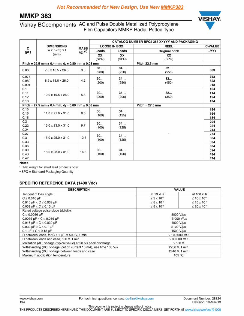
SPECIFIC REFERENCE DATA (1400 Vdc)
C(µF)
DIMENSIONSw x h (h’) x l
(mm)
MASS(g) (1)
CATALOG NUMBER BFC2 383 XXYYY AND PACKAGINGLOOSE IN BOX REEL C-VALUE
Leads Leads Original pitch ..YYYXX
(SPQ)XX
(SPQ)XX
(SPQ)Pitch = 22.5 mm ± 0.4 mm; dt = 0.80 mm ± 0.08 mm Pitch 22.5 mm
0.068 7.0 x 16.5 x 26.5 3.030 ...(200)
34… (250)
32… (550)
683
0.0758.5 x 18.0 x 26.0 4.2
30… (200)
34…(250)
32… (450)
7530.082 8230.091 9130.1
10.0 x 19.5 x 26.0 5.330… (200)
34…(200)
32… (350)
1040.11 1140.12 1240.13 134Pitch = 27.5 mm ± 0.4 mm; dt = 0.80 mm ± 0.08 mm Pitch = 27.5 mm 0.15
11.0 x 21.0 x 31.0 8.030… (100)
34… (125)
-
1540.16 1640.18 1840.2
13.0 x 23.0 x 31.0 9.730… (100)
34… (125)
2040.22 2240.24 2440.27
15.0 x 25.0 x 31.0 12.630… (100)
34… (125)
2740.3 3040.33 3340.36
18.0 x 28.0 x 31.0 16.330… (100)
34… (100)
3640.39 3940.43 4340.47 474
DESCRIPTION VALUETangent of loss angle: at 10 kHz at 100 kHzC 0.016 µF 5 x 10⁻⁴ 10 x 10-4
0.016 µF C 0.039 µF 5 x 10⁻⁴ 15 x 10-4
0.039 µF C 0.13 µF 5 x 10⁻⁴ 20 x 10-4
Rated voltage pulse slope (dU/dt)R:C 0.0056 µF 8000 V/µs0.0056 µF C 0.016 µF 15 000 V/µs0.016 µF C 0.039 µF 4000 V/µs0.039 µF C 0.1 µF 2100 V/µs0.1 µF C 0.13 µF 1500 V/µsR between leads, for C 1 µF at 500 V, 1 min 100 000 MR between leads and case, 500 V, 1 min 30 000 MIonization (AC) voltage (typical value) at 20 pC peak discharge 500 VWithstanding (DC) voltage (cut off current 10 mA), rise time 100 V/s 2250 V, 1 minWithstanding (DC) voltage between leads and case 2840 V, 1 minMaximum application temperature 105 °C
Document Number: 28124 For technical questions, contact: [email protected] www.vishay.comRevision: 19-Mar-13 195
MMKP 383AC and Pulse Double Metallized Polypropylene
Film Capacitors MMKP Radial Potted TypeVishay BCcomponents
This document is subject to change without notice.THE PRODUCTS DESCRIBED HEREIN AND THIS DOCUMENT ARE SUBJECT TO SPECIFIC DISCLAIMERS, SET FORTH AT www.vishay.com/doc?91000
Not Recommended for New Design, Use New MMKP383
URdc = 1400 V; URac = 500 V; Up-p = 1400 V; C-tol. = ± 5 %
Notes(1) Net weight for short lead products only• SPQ = Standard Packaging Quantity
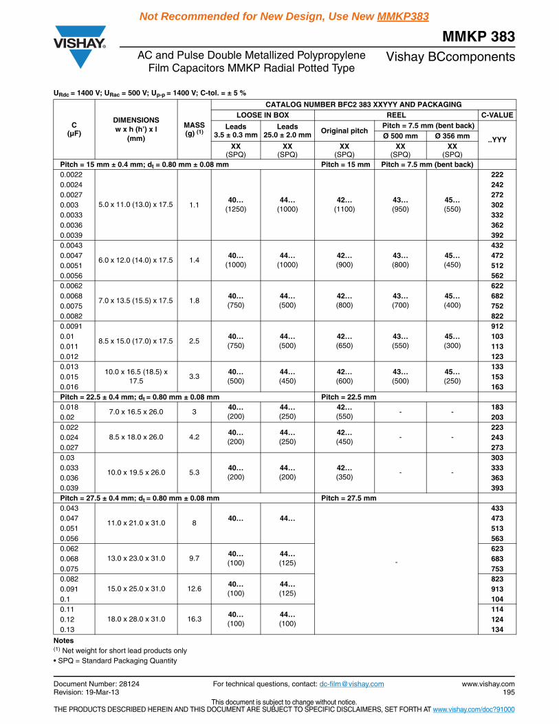
C(µF)
DIMENSIONSw x h (h’) x l
(mm)
MASS(g) (1)
CATALOG NUMBER BFC2 383 XXYYY AND PACKAGINGLOOSE IN BOX REEL C-VALUE
Leads 3.5 ± 0.3 mm
Leads 25.0 ± 2.0 mm Original pitch
Pitch = 7.5 mm (bent back)
..YYYØ 500 mm Ø 356 mmXX
(SPQ)XX
(SPQ)XX
(SPQ)XX
(SPQ)XX
(SPQ)Pitch = 15 mm ± 0.4 mm; dt = 0.80 mm ± 0.08 mm Pitch = 15 mm Pitch = 7.5 mm (bent back)0.0022
5.0 x 11.0 (13.0) x 17.5 40…
(1250) 44…
(1000) 42…
(1100) 43… (950)
45…(550)
2220.0024 2420.0027 2720.003 1.1 3020.0033 3320.0036 3620.0039 3920.0043
6.0 x 12.0 (14.0) x 17.5 1.440…
(1000) 44…
(1000) 42…(900)
43… (800)
45…(450)
4320.0047 4720.0051 5120.0056 5620.0062
7.0 x 13.5 (15.5) x 17.5 1.840… (750)
44… (500)
42… (800)
43… (700)
45…(400)
6220.0068 6820.0075 7520.0082 8220.0091
8.5 x 15.0 (17.0) x 17.5 2.540… (750)
44…(500)
42…(650)
43… (550)
45…(300)
9120.01 1030.011 1130.012 1230.013
10.0 x 16.5 (18.5) x 17.5
3.340… (500)
44…(450)
42…(600)
43… (500)
45… (250)
1330.015 1530.016 163Pitch = 22.5 ± 0.4 mm; dt = 0.80 mm ± 0.08 mm Pitch = 22.5 mm 0.018
7.0 x 16.5 x 26.0 340… (200)
44… (250)
42…(550)
- -183
0.02 2030.022
8.5 x 18.0 x 26.0 4.240… (200)
44… (250)
42… (450)
- -223
0.024 2430.027 2730.03
10.0 x 19.5 x 26.0 5.340… (200)
44…(200)
42…(350)
- -
3030.033 3330.036 3630.039 393Pitch = 27.5 ± 0.4 mm; dt = 0.80 mm ± 0.08 mm Pitch = 27.5 mm 0.043
11.0 x 21.0 x 31.0 8
-
4330.047 40… 44… 4730.051 5130.056 5630.062
13.0 x 23.0 x 31.0 9.740… (100)
44…(125)
6230.068 6830.075 7530.082
15.0 x 25.0 x 31.0 12.640…(100)
44… (125)
8230.091 9130.1 1040.11
18.0 x 28.0 x 31.0 16.340…(100)
44… (100)
1140.12 1240.13 134

MMKP 383Vishay BCcomponents AC and Pulse Double Metallized Polypropylene
Film Capacitors MMKP Radial Potted Type
www.vishay.com For technical questions, contact: [email protected] Document Number: 28124196 Revision: 19-Mar-13
This document is subject to change without notice.THE PRODUCTS DESCRIBED HEREIN AND THIS DOCUMENT ARE SUBJECT TO SPECIFIC DISCLAIMERS, SET FORTH AT www.vishay.com/doc?91000
Not Recommended for New Design, Use New MMKP383
SPECIFIC REFERENCE DATA (1600 Vdc)
URdc = 1600 V; URac = 550 V; Up-p = 1600 V; C-tol. = ± 5 %
DESCRIPTION VALUETangent of loss angle: at 10 kHz at 100 kHzC 0.015 µF 5 x 10⁻⁴ 15 x 10-4
0.015 µF C 0.15 µF 5 x 10⁻⁴ 20 x 10-4
Rated voltage pulse slope (dU/dt)R:C 0.0056 µF 8000 V/µs0.0056 µF C 0.0075 µF 15 000 V/µs0.0075 µF C 0.039 µF 3100 V/µs0.039 µF C 0.1 µF 1800 V/µs0.1 µF C 0.15 µF 1200 V/µsR between leads, for C 1 µF at 500 V, 1 min 100 000 MR between leads and case, 500 V, 1 min 30 000 MIonization (AC) voltage (typical value) at 20 pC peak discharge 660 VWithstanding (DC) voltage (cut off current 10 mA), rise time 100 V/s 2560 V, 1 minWithstanding (DC) voltage between leads and case 2840 V, 1 minMaximum aplication temperature 105 °C
C(µF)
DIMENSIONSw x h (h’) x l
(mm)
MASS(g) (1)
CATALOG NUMBER BFC2 383 XXYYY AND PACKAGINGLOOSE IN BOX REEL C-VALUE
Leads 3.5 ± 0.3
Leads 25.0 ± 2.0 Original pitch
Pitch = 7.5 mm (bent back)
..YYYØ 500 mm Ø 356 mmXX
(SPQ)XX
(SPQ)XX
(SPQ)XX
(SPQ)XX
(SPQ)Pitch = 15 mm ± 0.4 mm; dt = 0.80 mm ± 0.08 mm Pitch = 15 mm Pitch = 7.5 mm (bent back)0.0027
5.0 x 11.0 (13.0) x 17.5 1.150…
(1250) 54…
(1000) 52…
(1100) 53… (950)
55… (550)
2720.003 3020.0033 3320.0036 3620.0039 3920.0043
6.0 x 12.0 (14.0) x 17.5 1.450…
(1000) 54…
(1000) 52… (900)
53… (800)
55… (450)
4320.0047 4720.0051 5120.0056 5620.0062
7.0 x 13.5 (15.5) x 17.5 1.850… (750)
54… (500)
52…(800)
53… (700)
55… (400)
6220.0068 6820.0075 7520.0082
8.5 x 15.0 (17.0) x 17.5 2.550…(750)
54… (500)
52… (650)
53… (550)
55… (300)
8220.0091 9120.01 1030.011 1130.012
10.0 x 16.5 (18.5) x 17.5 3.350…(500)
54… (450)
52…(600)
53… (500)
55… (250)
1230.013 1330.015 153Pitch = 22.5 ± 0.4 mm; dt = 0.80 mm ± 0.08 mm Pitch = 22.5 mm 0.016
7.0 x 16.5 x 26.0 3.050…(200)
54…(250)
52… (550)
- -163
0.018 1830.02 2030.022
8.5 x 18.0 x 26.0 4.250… (200)
54… (250)
52…(450)
- -
2230.024 2430.027 2730.03 3030.033 10.0 x 19.5 x 26.0
5.3
50… (200)
54…(200)
52…(350)
- -333
0.036 3630.039 393
Notes(1) Net weight for short lead products only• SPQ = Standard Packaging Quantity

Document Number: 28124 For technical questions, contact: [email protected] www.vishay.comRevision: 19-Mar-13 197
MMKP 383AC and Pulse Double Metallized Polypropylene
Film Capacitors MMKP Radial Potted TypeVishay BCcomponents
This document is subject to change without notice.THE PRODUCTS DESCRIBED HEREIN AND THIS DOCUMENT ARE SUBJECT TO SPECIFIC DISCLAIMERS, SET FORTH AT www.vishay.com/doc?91000
Not Recommended for New Design, Use New MMKP383
Notes(1) Net weight for short lead products only• SPQ = Standard Packaging Quantity
SPECIFIC REFERENCE DATA (2000 Vdc)
URdc = 1600 V; URac = 550 V; Up-p = 1600 V; C-tol. = ± 5 %
C(µF)
DIMENSIONSw x h (h’) x l
(mm)
MASS(g) (1)
CATALOG NUMBER BFC2 383 XXYYY AND PACKAGINGLOOSE IN BOX REEL C-VALUE
Leads 3.5 ± 0.3
Leads 25.0 ± 2.0 Original pitch
Pitch = 7.5 mm (bent back)
..YYYØ 500 mm Ø 356 mmXX
(SPQ)XX
(SPQ)XX
(SPQ)XX
(SPQ)XX
(SPQ)
Pitch = 27.5 ± 0.4 mm; dt= 0.80 mm ± 0.08 mm Pitch = 27.5 mm
0.043
11.0 x 21.0 x 31.0 850…(100)
54…(125)
-
433
0.047 473
0.051 513
0.056 563
0.062
13.0 x 23.0 x 31.0 9.750… (100)
54…(125)
623
0.068 683
0.075 753
0.082
15.0 x 25.0 x 31.0 12.650… (100)
54… (125)
823
0.091 913
0.1 104
0.11
18.0 x 28.0 x 31.0 16.350… (100)
54… (100)
114
0.12 124
0.13 134
0.15 154
DESCRIPTION VALUETangent of loss angle: at 10 kHz at 100 kHzC 0.01 µF 5 x 10⁻⁴ 15 x 10-4
0.01 µF C 0.1 µF 10 x 10-4 18 x 10-4
Rated voltage pulse slope (dU/dt)R:C 0.0036 µF 11 000 V/µs0.0036 µF C 0.01 µF 20 000 V/µs0.01 µF C 0.024 µF 4400 V/µs0.024 µF C 0.068 µF 2500 V/µs0.068 µF C 0.1 µF 1800 V/µsR between leads, for C 1 µF at 500 V, 1 min 100 000 MR between leads and case, 500 V, 1 min 30 000 MIonization (AC) voltage (typical value) at 20 pC peak discharge 750 VWithstanding (DC) voltage (cut off current 10 mA), rise time 100 V/s 3200 V, 1 minWithstanding (DC) voltage between leads and case 2840 V, 1 minMaximum application temperature 105 °C

MMKP 383Vishay BCcomponents AC and Pulse Double Metallized Polypropylene
Film Capacitors MMKP Radial Potted Type
www.vishay.com For technical questions, contact: [email protected] Document Number: 28124198 Revision: 19-Mar-13
This document is subject to change without notice.THE PRODUCTS DESCRIBED HEREIN AND THIS DOCUMENT ARE SUBJECT TO SPECIFIC DISCLAIMERS, SET FORTH AT www.vishay.com/doc?91000
Not Recommended for New Design, Use New MMKP383
URdc = 2000 V; URac = 700 V; Up-p = 2000 V; C-tol. = ± 5 %
Notes(1) Net weight for short lead products only• SPQ = Standard Packaging Quantity
C(µF)
DIMENSIONSw x h (h’) x l
(mm)
MASS(g) (1)
CATALOG NUMBER BFC2 383 XXYYY AND PACKAGINGLOOSE IN BOX REEL C-VALUE
Leads 3.5 ± 0.3
Leads 25.0 ± 2.0 Original pitch
Pitch = 7.5 mm (bent back)
..YYYØ 500 mm Ø 356 mmXX
(SPQ)XX
(SPQ)XX
(SPQ)XX
(SPQ)XX
(SPQ)Pitch = 15 mm ± 0.4 mm; dt = 0.80 mm ± 0.08 mm Pitch = 15 mm Pitch = 7.5 mm (bent back)
0.001
5.0 x 11.0 (13.0) x 17.5 1.160…
(1250) 64…
(1000) 62…
(1100) 63… (950)
65… (550)
102
0.0011 112
0.0012 122
0.0013 132
0.0015 152
0.0016 162
0.0018 182
0.002 202
0.0022 222
0.0024 242
0.0027
6.0 x 12.0 (14.0) x 17.5 1.460…
(1000) 64…
(1000) 62… (900)
63…(800)
65… (450)
272
0.003 302
0.0033 332
0.0036 362
0.0039
7.0 x 13.5 (15.5) x 17.5 1.860…(750)
64… (500)
62…(800)
63… (700)
65… (400)
392
0.0043 432
0.0047 472
0.0051
8.5 x 15.0 (17.0) x 17.5 2.560… (750)
64…(500)
62… (650)
63… (550)
65…(300)
512
0.0056 562
0.0062 622
0.0068 682
0.0075
10.0 x 16.5 (18.5) x 17.5 3.360… (500)
64…(450)
62… (600)
63…(500)
65… (250)
752
0.0082 822
0.0091 912
0.01 103
Pitch = 22.5 mm ± 0.4 mm; dt = 0.80 mm ± 0.08 mm Pitch = 22.5 mm
0.011
7.0 x 16.5 x 26.0 3.060…(200)
64… (250)
62…(550)
113
0.012 - - 123
0.013 133
0.015
8.5 x 18.0 x 26.0 4.260…(200)
64… (250)
62… (450)
153
0.016 - - 163
0.018 183
0.02
10.0 x 19.5 x 26.0 5.360… (200)
64…(200)
62…(350)
203
0.022 - - 223
0.024 243
Pitch = 27.5 mm ± 0.4 mm; dt = 0.80 mm ± 0.08 mm Pitch = 27.5 mm
0.027
11.0 x 21.0 x 31.0 8.060… (100)
64… (125)
-
273
0.03 303
0.033 333
0.036 363
0.039 393

Document Number: 28124 For technical questions, contact: [email protected] www.vishay.comRevision: 19-Mar-13 199
MMKP 383AC and Pulse Double Metallized Polypropylene
Film Capacitors MMKP Radial Potted TypeVishay BCcomponents
This document is subject to change without notice.THE PRODUCTS DESCRIBED HEREIN AND THIS DOCUMENT ARE SUBJECT TO SPECIFIC DISCLAIMERS, SET FORTH AT www.vishay.com/doc?91000
Not Recommended for New Design, Use New MMKP383
Notes(1) Net weight for short lead products only• SPQ = Standard Packaging Quantity
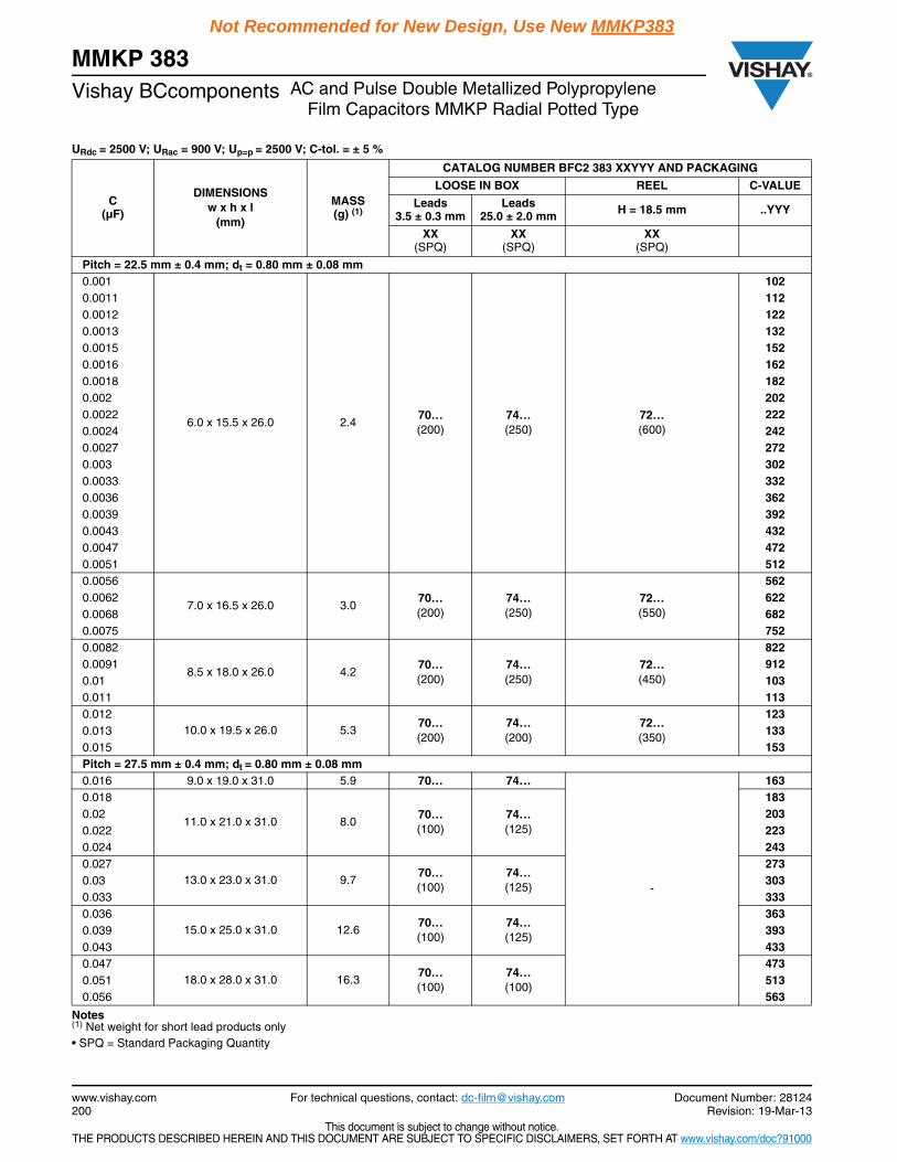
SPECIFIC REFERENCE DATA (2500 Vdc)
C(µF)
DIMENSIONSw x h (h’) x l
(mm)
MASS(g) (1)
CATALOG NUMBER BFC2 383 XXYYY AND PACKAGINGLOOSE IN BOX REEL C-VALUE
Leads 3.5 ± 0.3
Leads 25.0 ± 2.0 Original pitch
Pitch = 7.5 mm (bent back)
..YYYØ 500 mm Ø 356 mmXX
(SPQ)XX
(SPQ)XX
(SPQ)XX
(SPQ)XX
(SPQ)Pitch = 27.5 mm ± 0.4 mm; dt = 0.80 mm ± 0.08 mm Pitch = 27.5 mm
0.043
13.0 x 23.0 x 31.0 9.760… (100)
64… (125)
-
433
0.047 473
0.051 513
0.056
15.0 x 25.0 x 31.0 12.660… (100)
64… (125)
563
0.062 623
0.068 683
0.075
18.0 x 28.0 x 31.0 16.360… (100)
64… (100)
753
0.082 823
0.091 913
0.10 104
DESCRIPTION VALUETangent of loss angle: at 10 kHz at 100 kHz
C 0.015 µF 5 x 10⁻⁴ 10 x 10-4
0.015 µF C 0.056 µF 5 x 10⁻⁴ 15x 10-4
Rated voltage pulse slope (dU/dt)R:
C 0.015 µF 13 000 V/µs
0.015 µF C 0.043 µF 6000 V/µs
0.043 µF C 0.056 µF 4200 V/µs
R between leads, for C 1 µF at 500 V, 1 min 100 000 M
R between leads and case, 500 V, 1 min 30 000 M
Ionization (AC) voltage (typical value) at 20 pC peak discharge 1000 V
Withstanding (DC) voltage (cut off current 10 mA), rise time 100 V/s 3500 V, 1 min
Withstanding (DC) voltage between leads and case 2840 V, 1 min
Maximum application temperature 105 °C
MMKP 383Vishay BCcomponents AC and Pulse Double Metallized Polypropylene
Film Capacitors MMKP Radial Potted Type
www.vishay.com For technical questions, contact: [email protected] Document Number: 28124200 Revision: 19-Mar-13
This document is subject to change without notice.THE PRODUCTS DESCRIBED HEREIN AND THIS DOCUMENT ARE SUBJECT TO SPECIFIC DISCLAIMERS, SET FORTH AT www.vishay.com/doc?91000
Not Recommended for New Design, Use New MMKP383
URdc = 2500 V; URac = 900 V; Up=p = 2500 V; C-tol. = ± 5 %
Notes(1) Net weight for short lead products only• SPQ = Standard Packaging Quantity
C(µF)
DIMENSIONSw x h x l
(mm)
MASS(g) (1)
CATALOG NUMBER BFC2 383 XXYYY AND PACKAGING
LOOSE IN BOX REEL C-VALUE
Leads 3.5 ± 0.3 mm
Leads 25.0 ± 2.0 mm H = 18.5 mm ..YYY
XX(SPQ)
XX(SPQ)
XX(SPQ)
Pitch = 22.5 mm ± 0.4 mm; dt = 0.80 mm ± 0.08 mm0.001
6.0 x 15.5 x 26.0 2.470… (200)
74… (250)
72… (600)
1020.0011 1120.0012 1220.0013 1320.0015 1520.0016 1620.0018 1820.002 2020.0022 2220.0024 2420.0027 2720.003 3020.0033 3320.0036 3620.0039 3920.0043 4320.0047 4720.0051 5120.0056
7.0 x 16.5 x 26.0 3.070… (200)
74…(250)
72… (550)
5620.0062 6220.0068 6820.0075 7520.0082
8.5 x 18.0 x 26.0 4.270… (200)
74…(250)
72… (450)
8220.0091 9120.01 1030.011 1130.012
10.0 x 19.5 x 26.0 5.370… (200)
74… (200)
72… (350)
1230.013 1330.015 153Pitch = 27.5 mm ± 0.4 mm; dt = 0.80 mm ± 0.08 mm 0.016 9.0 x 19.0 x 31.0 5.9 70… 74…
-
1630.018
11.0 x 21.0 x 31.0 8.070… (100)
74…(125)
1830.02 2030.022 2230.024 2430.027
13.0 x 23.0 x 31.0 9.770… (100)
74… (125)
2730.03 3030.033 3330.036
15.0 x 25.0 x 31.0 12.670… (100)
74…(125)
3630.039 3930.043 4330.047
18.0 x 28.0 x 31.0 16.370… (100)
74… (100)
4730.051 5130.056 563

Document Number: 28124 For technical questions, contact: [email protected] www.vishay.comRevision: 19-Mar-13 201
MMKP 383AC and Pulse Double Metallized Polypropylene
Film Capacitors MMKP Radial Potted TypeVishay BCcomponents
This document is subject to change without notice.THE PRODUCTS DESCRIBED HEREIN AND THIS DOCUMENT ARE SUBJECT TO SPECIFIC DISCLAIMERS, SET FORTH AT www.vishay.com/doc?91000
Not Recommended for New Design, Use New MMKP383
MOUNTING
Normal UseThe capacitors are designed for mounting on printed-circuit boards. The capacitors packed in bandoliers are designed formounting on printed-circuit boards by means of automatic insertion machines.For detailed tape specifications refer to “Packaging Information” www.vishay.com/docs?28139
Specific Method of Mounting to Withstand Vibration and Shock
In order to withstand vibration and shock tests, it must be ensured that the stand-off pips are in good contact with theprinted-circuit board:
For original pitch 15 mmthe capacitors shall be mechanically fixed by the leads
For larger pitches the capacitors shall be mounted in the same way and the body clamped
Space Requirements on Printed-Circuit Board
The maximum length and width of film capacitors is shown in the drawing: Eccentricity as in drawing. The maximum eccentricity is smaller than or equal to the lead diameter of the product concerned
Product height with seating plane as given by “IEC 60717” as reference: hmax. h + 0.3 mm
Storage Temperature
Storage temperature: Tstg = - 25 °C to + 40 °C with RH maximum 80 % without condensation
Ratings and Characteristics Reference Conditions
Unless otherwise specified, all electrical values apply to an ambient free temperature of 23 °C ± 1 °C, an atmospheric pressureof 86 kPa to 106 kPa and a relative humidity of 50 % ± 2 %.
For reference testing, a conditioning period shall be applied over 96 h ± 4 h by heating the products in a circulating air oven atthe rated temperature and a relative humidity not exceeding 20 %.
Eccentricity
Imax. = I + 0.3 mm
bmax. = b + 0.3 mm
MMKP 383Vishay BCcomponents AC and Pulse Double Metallized Polypropylene
Film Capacitors MMKP Radial Potted Type
www.vishay.com For technical questions, contact: [email protected] Document Number: 28124202 Revision: 19-Mar-13
This document is subject to change without notice.THE PRODUCTS DESCRIBED HEREIN AND THIS DOCUMENT ARE SUBJECT TO SPECIFIC DISCLAIMERS, SET FORTH AT www.vishay.com/doc?91000
Not Recommended for New Design, Use New MMKP383
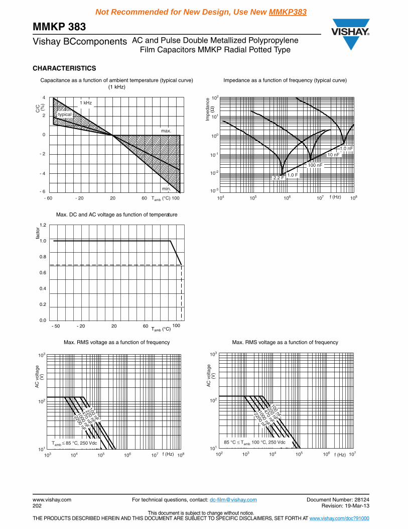
CHARACTERISTICS
Capacitance as a function of ambient temperature (typical curve) (1 kHz)
Impedance as a function of frequency (typical curve)
Max. DC and AC voltage as function of temperature
Max. RMS voltage as a function of frequency Max. RMS voltage as a function of frequency
typical
1 kHz
- 60
C/C
(%
)
4
0
- 2
- 4
- 6
2
- 20 20 60 100Tamb (°C)
min.
max.
2.2 F1.0 F
100 nF
10 nF1.0 nF
Impe
danc
e(Ω
)
102
101
100
10-1
10-2
10-3
f (Hz)104 105 106 107 108
fact
or
Tamb (°C)
1.0
0.8
0.6
0.4
0.0
0.2
1.2
- 50 - 20 60 100 20
103
102
101
f (Hz)104103 105 106 107 108
220 nF
470 nF
1000 nF
2200 nF100 nF
Tamb ≤ 85 °C, 250 Vdc
AC
vol
tage
(V)
103
102
101
f (Hz)103102 104 105 106 107
AC
vol
tage
(V)
220 nF
470 nF
1000 nF
2200 nF
100 nF
85 °C ≤ Tamb 100 °C, 250 Vdc

Document Number: 28124 For technical questions, contact: [email protected] www.vishay.comRevision: 19-Mar-13 203
MMKP 383AC and Pulse Double Metallized Polypropylene
Film Capacitors MMKP Radial Potted TypeVishay BCcomponents
This document is subject to change without notice.THE PRODUCTS DESCRIBED HEREIN AND THIS DOCUMENT ARE SUBJECT TO SPECIFIC DISCLAIMERS, SET FORTH AT www.vishay.com/doc?91000
Not Recommended for New Design, Use New MMKP383
Max. RMS voltage as a function of frequency Max. RMS voltage as a function of frequency
Max. RMS voltage as a function of frequency Max. RMS voltage as a function of frequency
Max. RMS voltage as a function of frequency Max. RMS voltage as a function of frequency
103
102
101
f (Hz)104103 105 106 107 108
AC
vol
tage
(V)
220 nF
470 nF
1000 nF100 nF
Tamb ≤ 85 °C, 400 Vdc
47 nF
103
102
101
f (Hz)103102 104 105 106 107
AC
vol
tage
(V)
220 nF
470 nF
1000 nF
85 °C < Tamb ≤ 100 °C, 400 Vdc
47 nF
100 nF
103
102
101
f (Hz)104103 105 106 107 108
AC
vol
tage
(V)
Tamb ≤ 85 °C, 630 Vdc
220 nF
470 nF
1000 nF100 nF47 nF
103
102
101
f (Hz)103102 104 105 106 107
AC
vol
tage
(V)
85 °C < Tamb ≤ 100 °C, 630 Vdc
220 nF
470 nF
1000 nF100 nF47 nF
103
102
101
f (Hz)104103 105 106 107 108
AC
vol
tage
(V)
Tamb ≤ 85 °C, 1000 Vdc
22 nF
47 nF
100 nF
220 nF
470 nF
10 nF4.7 nF
103
102
101
f (Hz)103102 104 105 106 107
AC
vol
tage
(V)
85 °C < Tamb ≤ 100 °C, 1000 Vdc
4.7 nF
220 nF
470 nF100 nF47 nF
22 nF10 nF

MMKP 383Vishay BCcomponents AC and Pulse Double Metallized Polypropylene
Film Capacitors MMKP Radial Potted Type
www.vishay.com For technical questions, contact: [email protected] Document Number: 28124204 Revision: 19-Mar-13
This document is subject to change without notice.THE PRODUCTS DESCRIBED HEREIN AND THIS DOCUMENT ARE SUBJECT TO SPECIFIC DISCLAIMERS, SET FORTH AT www.vishay.com/doc?91000
Not Recommended for New Design, Use New MMKP383
Max. RMS voltage as a function of frequency Max. RMS voltage as a function of frequency
Max. RMS voltage as a function of frequency Max. RMS voltage as a function of frequency
Max. RMS voltage as a function of frequency Max. RMS voltage as a function of frequency
2.2 nF
Tamb ≤ 85 °C, 1400 Vdc
47 nF22 nF
10 nF4.7 nF100 nF
103
102
101
f (Hz)104103 105 106 107 108
AC
vol
tage
(V)
85 °C < Tamb ≤ 105 °C, 1400 Vdc
2.2 nF47 nF22 nF
10 nF4.7 nF100 nF
103
102
101
f (Hz)103102 104 105 106 107
AC
vol
tage
(V)
103
102
101
f (Hz)104103 105 106 107 108
AC
vol
tage
(V)
Tamb ≤ 85 °C, 1600 Vdc4.7 nF47 nF
22 nF10 nF100 nF
103
102
101
f (Hz)103102 104 105 106 107
AC
vol
tage
(V)
85 °C < Tamb ≤ 100 °C, 1600 Vdc
4.7 nF47 nF22 nF
10 nF100 nF
103
102
101
f (Hz)104103 105 106 107 108
AC
vol
tage
(V)
Tamb ≤ 85 °C, 2000 Vdc
47 nF22 nF
10 nF4.7 nF100 nF
2.2 nF1.0 nF
103
102
101
f (Hz)103102 104 105 106 107
AC
vol
tage
(V)
85 °C < Tamb ≤ 100 °C, 2000 Vdc
1.0 nF
47 nF22 nF
10 nF4.7 nF100 nF
2.2 nF

Document Number: 28124 For technical questions, contact: [email protected] www.vishay.comRevision: 19-Mar-13 205
MMKP 383AC and Pulse Double Metallized Polypropylene
Film Capacitors MMKP Radial Potted TypeVishay BCcomponents
This document is subject to change without notice.THE PRODUCTS DESCRIBED HEREIN AND THIS DOCUMENT ARE SUBJECT TO SPECIFIC DISCLAIMERS, SET FORTH AT www.vishay.com/doc?91000
Not Recommended for New Design, Use New MMKP383
Max. RMS voltage as a function of frequency Max. RMS voltage as a function of frequency
Insulation resistance as a function of ambient temperature Max. allowed component temperature rise (T) as a function of the ambient temperature (Tamb)
Tamb ≤ 85 °C, 2500 Vdc
1.0 nF
47 nF22 nF
10 nF4.7 nF
2.2 nF
103
102
101
f (Hz)104103 105 106 107 108
AC
vol
tage
(V)
85 °C < Tamb ≤ 105 °C, 2500 Vdc
47 nF22 nF
10 nF4.7 nF
2.2 nF1.0 nF
103
102
101
f (Hz)103102 104 105 106 107
AC
vol
tage
(V)
106
105
104
0 20 40 60 80 100Tamb (°C)
RC
(s)
Tamb (°C)- 50 - 20 60 100 200
4
8
12
ΔT (
°C)

MMKP 383Vishay BCcomponents AC and Pulse Double Metallized Polypropylene
Film Capacitors MMKP Radial Potted Type
www.vishay.com For technical questions, contact: [email protected] Document Number: 28124206 Revision: 19-Mar-13
This document is subject to change without notice.THE PRODUCTS DESCRIBED HEREIN AND THIS DOCUMENT ARE SUBJECT TO SPECIFIC DISCLAIMERS, SET FORTH AT www.vishay.com/doc?91000
Not Recommended for New Design, Use New MMKP383
HEAT CONDUCTIVITY (G) AS A FUNCTION OF (ORIGINAL) PITCH AND CAPACITOR BODY THICKNESS IN mW/°C
Tangent of loss angle as a function of frequency (typical curve)
250 V 400 V 630 V 1000 VC 0.091 µF, curve 8 C 0.047 µF, curve 5 C 0.033 µF, curve 4 C 0.01 µF, curve 2C 0.015 µF, curve 9 C 0.068 µF, curve 6 C 0.068 µF, curve 5 C 0.027 µF, curve 3C 0.022 µF, curve 10 C 0.1 µF, curve 7 C 0.1 µF, curve 6 C 0.047 µF, curve 4C 0.027 µF, curve 11 C 0.2 µF, curve8 C 0.15 µF, curve 7 C 0.062 µF, curve 5C 0.033 µF, curve 12 C 0.24 µF, curve 12 C 0.22 µF, curve 11 C 0.075 µF, curve 6C 0.056 µF, curve 15 C 0.36 µF, curve 13 C 0.27 µF, curve 12 C 0.1 µF, curve 7C 0.082 µF, curve 16 C 0.43 µF, curve 14 C 0.47 µF, curve 15 C 0.15 µF, curve 8C 1.2 µF, curve 18 C 56 µF, curve 16 C 0.68 µF, curve 16 C 0.22 µF, curve 9C 1.61 µF, curve 19 C 1.1 µF, curve 17 C 0.3 µF, curve 10C 2.21 µF, curve 20 C 0.39 µF, curve 11
C 0.47 µF, curve 12
140 V 1600 V 2000 V 2500 VC 0.0047 µF, curve 1 C 0.0047 µF, curve 3 C 0.0047 µF, curve 2 C 0.0047 µF, curve 1C 0.016 µF, curve 2 C 0.0091 µF, curve 4 C 0.033 µF, curve 3 C 0.015 µF, curve 2C 0.033 µF, curve 3 C 0.068 µF, curve 5 C 0.1 µF, curve 4 C 0.056 µF, curve 3C 0.051 µF, curve 4 C 0.01 µF, curve 6C 0.068 µF, curve 5 C 0.15 µF, curve 7C 0.082 µF, curve 6C 0.1 µF, curve 7
Wmax.
(mm)HEAT CONDUCTIVITY (mW/°C)
PITCH 15 mm PITCH 22.5 mm PITCH 27.5 mm
4.0 - - -5.0 10 - -6.0 11 19 -7.0 12 21 -8.5 16 25 -
10.0 18 28 -11.0 - - 3613.0 - - 4215.0 - - 4818.0 - - 57
Dis
sipa
tion
fact
or (
x 10
-4) 103
102
100
101
(Hz) 103 102 104 105 106
20191817
16151413121110987654321

Document Number: 28124 For technical questions, contact: [email protected] www.vishay.comRevision: 19-Mar-13 207
MMKP 383AC and Pulse Double Metallized Polypropylene
Film Capacitors MMKP Radial Potted TypeVishay BCcomponents
This document is subject to change without notice.THE PRODUCTS DESCRIBED HEREIN AND THIS DOCUMENT ARE SUBJECT TO SPECIFIC DISCLAIMERS, SET FORTH AT www.vishay.com/doc?91000
Not Recommended for New Design, Use New MMKP383
POWER DISSIPATION AND MAXIMUM COMPONENT TEMPERATURE RISE
The power dissipation must be limited in order not to exceed the maximum allowed component temperature rise as a function ofthe free air ambient temperature.The power dissipation can be calculated according type detail specification “HQN-384-01/101: Technical Information FilmCapacitors”.The component temperature rise (T) can be measured (see section “Measuring the component temperature” for more details)or calculated by T = P/G:
T = Component temperature rise (°C)
P = Power dissipation of the component (mW)
G = Heat conductivity of the component (mW/°C)
MEASURING THE COMPONENT TEMPERATURE
A thermocouple must be attached to the capacitor body as in:
The temperature is measured in unloaded (Tamb) and maximum loaded condition (TC).The temperature rise is given by T = TC - Tamb.To avoid radiation or convection, the capacitor should be tested in a wind-free box.
APPLICATION NOTE AND LIMITING CONDITIONS
These capacitors are not suitable for mains applications as across-the-line capacitors without additional protection, as describedhereunder. These mains applications are strictly regulated in safety standards and therefore electromagnetic interferencesuppression capacitors conforming the standards must be used.
To select the capacitor for a certain application, the following conditions must be checked:
1. The peak voltage (UP) shall not be greater than the rated DC voltage (URdc)
2. The peak-to-peak voltage (UP-P) shall not be greater than 22 x URac to avoid the ionisation inception level
3. The voltage pulse slope (dU/dt) shall not exceed the rated voltage pulse slope in an RC-circuit at rated voltage and withoutringing. If the pulse voltage is lower than the rated DC voltage, the rated voltage pulse slope may be multiplied by URdc anddivided by the applied voltage.For all other pulses following equation must be fulfilled:
T is the pulse duration.
4. The maximum component surface temperature rise must be lower than the limits (see graph max. allowed componenttemperature rise).
5. Since in circuits used at voltages over 280 V peak-to-peak the risk for an intrinsically active flammability after a capacitorbreakdown (short circuit) increases, it is recommended that the power to the component is limited to 100 times the valuesmentioned in the table: “Heat Conductivity”
Thermocouple
2 dUdt-------- 2
0
T
dt URdcdUdt--------
rated

MMKP 383Vishay BCcomponents AC and Pulse Double Metallized Polypropylene
Film Capacitors MMKP Radial Potted Type
www.vishay.com For technical questions, contact: [email protected] Document Number: 28124208 Revision: 19-Mar-13
This document is subject to change without notice.THE PRODUCTS DESCRIBED HEREIN AND THIS DOCUMENT ARE SUBJECT TO SPECIFIC DISCLAIMERS, SET FORTH AT www.vishay.com/doc?91000
Not Recommended for New Design, Use New MMKP383
6. When using these capacitors as across-the-line capacitor in the input filter for mains applications or as series connected withan impedance to the mains the applicant must guarantee that the following conditions are fulfilled in any case (spikes andsurge voltages from the mains included).
Voltage Conditions for 6 Above
EXAMPLE
C = 4 nF - 1600 V used for the voltage signal shown in next drawing.UP-P = 1000 V; UP = 900 V; T1 = 12 µs; T2 = 64 µs; T3 = 4 µsThe ambient temperature is 80 °C. In case of failure, the oscillation is blocked.
Checking conditions:
1. The peak voltage UP = 900 V is lower than 1600 Vdc
2. The peak-to-peak voltage 1000 V is lower than 22 x 550 Vac = 1600 UP-P
3. The voltage pulse slope (dU/dt) = 1000 V/4 µs = 250 V/µsThis is lower than 8000 V/µs (see specific reference data for each version)
4. The dissipated power is 35 mW as calculated with fourier terms and typical tgd.The temperature rise for Wmax. = 6.0 mm and pitch = 15 mm will be 35 mW/11 mW/°C = 3.2 °CThis is lower than 10 °C temperature rise at 80 °C, according graph.
5. Oscillation is blocked6. Not applicable
Voltage Signal
ALLOWED VOLTAGES Tamb 85 °C 85 °C < Tamb 105 °C
Maximum continuous RMS voltage URac URac
Maximum temperature RMS-overvoltage (< 24 h) 1.25 x URac 1.25 x URac
Maximum peak voltage (VO-P) (< 2 s) 1.6 x URdc 1.1 x URdc
Voltage
Up
T3
T1
T2
Up-p
Time

Document Number: 28124 For technical questions, contact: [email protected] www.vishay.comRevision: 19-Mar-13 209
MMKP 383AC and Pulse Double Metallized Polypropylene
Film Capacitors MMKP Radial Potted TypeVishay BCcomponents
This document is subject to change without notice.THE PRODUCTS DESCRIBED HEREIN AND THIS DOCUMENT ARE SUBJECT TO SPECIFIC DISCLAIMERS, SET FORTH AT www.vishay.com/doc?91000
Not Recommended for New Design, Use New MMKP383
INSPECTION REQUIREMENTS
General Notes:Sub-clause numbers of tests and performance requirements refer to the “Sectional Specification, Publication IEC 60384-17 andSpecific Reference Data”.
Group C Inspection Requirements
SUB-CLAUSE NUMBER AND TEST CONDITIONS PERFORMANCE REQUIREMENTS
SUB-GROUP C1A PART OF SAMPLEOF SUB-GROUP C1
4.1 Dimensions (detail) As specified in chapters “General Data” of this specification
4.3.1 Initial measurements CapacitanceTangent of loss angle:
For C 1 µF at 100 kHz orfor C > 1 µF at 10 kHz
4.3 Robustness of terminations Tensile: Load 10 N; 10 sBending: Load 5 N; 4 x 90°
No visible damage
4.4 Resistance to soldering heat Method: 1ASolder bath: 280 °C ± 5 °CDuration: 10 s
4.14 Component solvent resistance Isopropylalcohol at room temperatureMethod: 2
Immersion time: 5 min ± 0.5 minRecovery time: Min. 1 h, max. 2 h
4.4.2 Final measurements Visual examination No visible damageLegible marking
Capacitance C/C| 1 % of the value measured initially
Tangent of loss angle Increase of tan 0.0005 for: C 100 nF or 0.001 for: 100 nF < C 470 nF or 0.0015 for: C 470 nF
Compared to values measured in 4.3.1
SUB-GROUP C1B OTHER PART OF SAMPLE OF SUB-GROUP C1
4.6.1 Initial measurements CapacitanceTangent of loss angle:
For C 1 µF at 100 kHz orfor C > 1 µF at 10 kHz
4.15 Solvent resistance of the marking Isopropylalcohol at room temperature Method: 1Rubbing material: cotton wool
No visible damageLegible marking
4.6 Rapid change of temperature Immersion time: 5.0 min ± 0.5 minA = - 55 °CB = + 105 °C5 cyclesDuration t = 30 min
4.7 Vibration Visual examinationMounting: see section “Mounting” for more informationProcedure B4
Frequency range: 10 Hz to 55 HzAmplitude: 0.75 mm orAcceleration 98 m/s² (whichever is less severe)Total duration 6 h
No visible damage

MMKP 383Vishay BCcomponents AC and Pulse Double Metallized Polypropylene
Film Capacitors MMKP Radial Potted Type
www.vishay.com For technical questions, contact: [email protected] Document Number: 28124210 Revision: 19-Mar-13
This document is subject to change without notice.THE PRODUCTS DESCRIBED HEREIN AND THIS DOCUMENT ARE SUBJECT TO SPECIFIC DISCLAIMERS, SET FORTH AT www.vishay.com/doc?91000
Not Recommended for New Design, Use New MMKP383
SUB-GROUP C1B OTHER PART OF SAMPLE OF SUB-GROUP C14.7.2 Final inspection Visual examination No visible damage4.9 Shock Mounting:
See section “Mounting” for more informationPulse shape: Half sineAcceleration: 490 m/s²Duration of pulse: 11 ms
4.9.3 Final measurements Visual examination No visible damageCapacitance C/C| 1 % of the value measured in 4.6.1Tangent of loss angle Increase of tan
0.0005 for: C 100 nF or 0.001 for: 100 nF < C 470 nF or 0.0015 for: C 470 nF
Compared to values measured in 4.6.1Insulation resistance As specified in section “Insulation
Resistance” of this specificationSUB-GROUP C1 COMBINED SAMPLE OF SPECIMENS OF SUB-GROUPS C1A AND C1B4.10 Climatic sequence4.10.2 Dry heat Temperature: + 105 °C
Duration: 16 h4.10.3 Damp heat cyclic
Test Db, first cycle4.10.4 Cold Temperature: - 55 °C
Duration: 2 h4.10.6 Damp heat cyclic
Test Db, remaining cycles4.10.6.2 Final measurements Voltage proof = URdc for 1 min within 15 min
after removal from testchamberNo breakdown of flash-over
Visual examination No visible damageLegible marking
Capacitance For original pitch = 22.5 mm and 27.5 mm:C/C| 3 % of the value measured in 4.4.2 or 4.9.3
Tangent of loss angle Increase of tan 0.0005 for: C 100 nF or 0.001 for: 100 nF < C 470 nF or 0.0015 for: C 470 nF
Compared to values measured in 4.3.1 or 4.6.1
Insulation resistance 50 % of values specified in section “Insulation Resistance” of this specification
SUB-GROUP C2
4.11 Damp heat steady state 56 days, 40 °C, 90 % to 95 % RH no load
4.11.1 Initial measurements CapacitanceTangent of loss angle at 1 kHz
4.11.3 Final measurements Voltage proof = URdc for 1 min within 15 min after removal from testchamber
No breakdown of flash-over
Visual examination No visible damageLegible marking
Capacitance |C/C| 1 % of the value measured in 4.11.1.
Tangent of loss angle Increase of tan 0.0005 for: C 100 nF or 0.001 for: 100 nF < C 470 nF or 0.0015 for: C 470 nF
Compared to values measured in 4.11.1Insulation resistance 50 % of values specified in section
“Insulation Resistance” of this specification
SUB-CLAUSE NUMBER AND TEST CONDITIONS PERFORMANCE REQUIREMENTS

Document Number: 28124 For technical questions, contact: [email protected] www.vishay.comRevision: 19-Mar-13 211
MMKP 383AC and Pulse Double Metallized Polypropylene
Film Capacitors MMKP Radial Potted TypeVishay BCcomponents
This document is subject to change without notice.THE PRODUCTS DESCRIBED HEREIN AND THIS DOCUMENT ARE SUBJECT TO SPECIFIC DISCLAIMERS, SET FORTH AT www.vishay.com/doc?91000
Not Recommended for New Design, Use New MMKP383
SUB-GROUP C3A
4.12.1 Endurance test at 50 Hz alternating voltage
Duration: 2000 h1.25 x URdc at 105 °C
4.12.1.1 Initial measurements CapacitanceTangent of loss angle:
For C 1 µF at 100 kHz orfor C > 1 µF at 10 kHz
4.12.1.3 Final measurements Visual examination No visible damageLegible marking
Capacitance |C/C| 5 % compared to values measured in 4.12.1.1
Tangent of loss angle Increase of tan 0.0005 for: C 100 nF or 0.001 for: 100 nF < C 470 nF or 0.0015 for: C 470 nF
Compared to values measured in 4.12.1.1
Insulation resistance 50 % of values specified in section “Insulation Resistance” of this specification
SUB-GROUP C4
4.2.6 Temperature charcteristicsInitial measurementsIntermediate measurements
Final measurements
Capacitance Capacitance at - 55 °CCapacitance at 20 °CCapacitance at + 105 °CCapacitance
Insulation resistance
For - 55 °C to + 20 °C:+ 1 % |C/C| 3.75 % or for 20 °C to 105 °C:- 6 % |C/C| 0 % As specified in section “Capacitance” of this specification.As specified in section “Insulation Resistance” of this specification
4.13 Charge and discharge 10 000 cyclesCharged to URdcDischarge resistance:
4.13.1 Initial measurements CapacitanceTangent of loss angle:
For C 1 µF at 100 kHz orfor C > 1 µF at 10 kHz
4.13.3 Final measurements Capacitance |C/C| 1 % compared to values measured in 4.13.1
Tangent of loss angle Increase of tan 0.0005 for: C 100 nF or 0.001 for: 100 nF < C 470 nF or 0.0015 for: C 470 nF
Compared to values measured in 4.13.1
Insulation resistance 50 % of values specified in section “Insulation Resistance” of this specification
SUB-CLAUSE NUMBER AND TEST CONDITIONS PERFORMANCE REQUIREMENTS
RURdc
5 x C x 2.5 x dU dt --------------------------------------------------------------=

Legal Disclaimer Noticewww.vishay.com Vishay
Revision: 08-Feb-17 1 Document Number: 91000
DisclaimerALL PRODUCT, PRODUCT SPECIFICATIONS AND DATA ARE SUBJECT TO CHANGE WITHOUT NOTICE TO IMPROVE RELIABILITY, FUNCTION OR DESIGN OR OTHERWISE.
Vishay Intertechnology, Inc., its affiliates, agents, and employees, and all persons acting on its or their behalf (collectively, “Vishay”), disclaim any and all liability for any errors, inaccuracies or incompleteness contained in any datasheet or in any other disclosure relating to any product.
Vishay makes no warranty, representation or guarantee regarding the suitability of the products for any particular purpose or the continuing production of any product. To the maximum extent permitted by applicable law, Vishay disclaims (i) any and all liability arising out of the application or use of any product, (ii) any and all liability, including without limitation special, consequential or incidental damages, and (iii) any and all implied warranties, including warranties of fitness for particular purpose, non-infringement and merchantability.
Statements regarding the suitability of products for certain types of applications are based on Vishay’s knowledge of typical requirements that are often placed on Vishay products in generic applications. Such statements are not binding statements about the suitability of products for a particular application. It is the customer’s responsibility to validate that a particular product with the properties described in the product specification is suitable for use in a particular application. Parameters provided in datasheets and / or specifications may vary in different applications and performance may vary over time. All operating parameters, including typical parameters, must be validated for each customer application by the customer’s technical experts. Product specifications do not expand or otherwise modify Vishay’s terms and conditions of purchase, including but not limited to the warranty expressed therein.
Except as expressly indicated in writing, Vishay products are not designed for use in medical, life-saving, or life-sustaining applications or for any other application in which the failure of the Vishay product could result in personal injury or death. Customers using or selling Vishay products not expressly indicated for use in such applications do so at their own risk. Please contact authorized Vishay personnel to obtain written terms and conditions regarding products designed for such applications.
No license, express or implied, by estoppel or otherwise, to any intellectual property rights is granted by this document or by any conduct of Vishay. Product names and markings noted herein may be trademarks of their respective owners.
© 2017 VISHAY INTERTECHNOLOGY, INC. ALL RIGHTS RESERVED