ac electrohydrodynamic landau–squire flows around a
TRANSCRIPT

J. Fluid Mech. (2021), vol. 925, A6, doi:10.1017/jfm.2021.656
AC electrohydrodynamic Landau–Squire flowsaround a conducting nanotip
Jyun-An Chen1, Touvia Miloh2, Watchareeya Kaveevivitchai1,3 andHsien-Hung Wei1,†1Department of Chemical Engineering, National Cheng Kung University, Tainan 701, Taiwan2School of Mechanical Engineering, University of Tel-Aviv, Tel-Aviv 69978, Israel3Hierarchical Green-Energy Materials (Hi-GEM) Research Center, National Cheng Kung University,Tainan 701, Taiwan
(Received 8 December 2020; revised 13 July 2021; accepted 18 July 2021)
Utilizing the joint singular natures of electric field and hydrodynamic flow around asharp nanotip, we report new electrohydrodynamic Landau–Squire-type flows under theactions of alternating current (AC) electric fields, markedly different from the classicalLandau–Squire flow generated by pump discharge using nanotubes or nanopores. Makinguse of the locally diverging electric field prevailing near the conical tip, we are ableto generate a diversity of AC electrohydrodynamic flows with the signature of a 1/rpoint-force-like decay at distance r from the tip. Specifically, we find AC electrothermaljet and Faradaic streaming out of the tip at applied frequencies in the MHz and 102 Hzregimes, respectively. Yet at intermediate frequencies of 1–100 kHz, the jet flow can bereversed to an AC electro-osmotic impinging flow. The characteristics of these AC jetflows are very distinct from AC flows over planar electrodes. For the AC electrothermaljet, we observe experimentally that its speed varies with the driving voltage V as V3,in contrast to the common V4 dependence according to the classical theory reportedby Ramos et al. (J. Phys. D: Appl. Phys, vol. 31, 1998, pp. 2338–2353). Additionally,the flow speed does not increase with the solution conductivity as commonly thought.These experimental findings can be rationalized by means of local Joule heating anddouble layer charging mechanisms in such a way that the nanotip actually becomesa local hotspot charged with heated tangential currents. The measured speed of theAC Faradaic streaming is found to vary as V3/2 logV, which can be interpreted bythe local Faradaic leakage in balance with tangential conduction. These unusual flowcharacteristics signify that a conical electrode geometry may fundamentally alter thefeatures of AC electrohydrodynamic flows. Such peculiar electrohydrodynamic flows may
† Email address for correspondence: [email protected]
© The Author(s), 2021. Published by Cambridge University Press. This is an Open Access article,distributed under the terms of the Creative Commons Attribution licence (http://creativecommons.org/licenses/by/4.0/), which permits unrestricted re-use, distribution, and reproduction in any medium,provided the original work is properly cited. 925 A6-1
Dow
nloa
ded
from
htt
ps://
ww
w.c
ambr
idge
.org
/cor
e. IP
add
ress
: 65.
21.2
28.1
67, o
n 07
Dec
202
1 at
09:
00:5
7, s
ubje
ct to
the
Cam
brid
ge C
ore
term
s of
use
, ava
ilabl
e at
htt
ps://
ww
w.c
ambr
idge
.org
/cor
e/te
rms.
htt
ps://
doi.o
rg/1
0.10
17/jf
m.2
021.
656
J.-A. Chen, T. Miloh, W. Kaveevivitchai and H.-H. Wei
also provide new avenues for expediting molecular sensing or sample transport in prevalentelectrochemical or microfluidic applications.
Key words: electrokinetic flows
1. Introduction
When pumping a fluid through a narrow tube into a large reservoir, one will generallyobserve a jet emerging from the end of the tube. Unlike a flow emanating from apoint-mass source, such a jet is discharged in a manner that the fluid momentum isconcentrated at the tip of the tube. When this momentum is released from the tip intothe vast bulk region, it will entrain and eject fluid around the edge, emitting a jet outof the tip. This is the well-known Landau–Squire (LS) jet driven by a point source of(constant) momentum. It has been shown that this particular jet flow admits an exact(self-similar) solution of the Navier–Stokes equation (Squire 1951; Landau & Lifshitz1959). The solution is constructed by assuming that the flow is symmetric about the polarangle in the direction of the jet. Expressed in axisymmetric spherical polar coordinates(r,θ ) with the tip as the origin, the fluid velocity (ur, uθ ) in the weak jet limit due to asmall point force F takes the following form (Landau & Lifshitz 1959):
(ur, uθ ) = F4πηr
(cos θ, −1
2sin θ
), (1.1)
where η denotes the dynamic viscosity of the fluid. The velocity (1.1) is shown to decayas 1/r away from the tip. From a dimensional point of view, this is the only plausiblesolution because the force F under the creeping flow condition is expressed as the productof viscosity, velocity and length scale.
Experimentally, LS flows are commonly realized by pressure discharge usingnanopipettes or conical nanopores that are able to render pressure buildup at their tips,as seen for example in nanovelocimetry or nanofluidic ionic diodes (Laohakunakorn et al.2013; Lan et al. 2016; Secchi et al. 2016; Wu, Rajasekaran & Martin 2016). In contrast tosuch familiar pump discharge LS flows at nanoscales, in this work we demonstrate bothexperimentally and theoretically that a new class of LS-type flow can be generated in apurely electrohydrodynamic (EHD) manner. This can be done by applying an ambientuniform AC electric field over a sharp conducting needle at microscales. The effect iscapable of producing not only a jet-like streaming from the tip but also a reverse flowpattern, which is very distinct from the classical LS flow. Prior to presenting our results,we explain below our incentives for studying such EHD LS-type flows.
The typical 1/r velocity field divergence of the LS flow at the discharge tip is a result ofthe point momentum exerted at the conical tip. This 1/r velocity dependence is exactly thesignature of the fundamental Stokeslet point-force solution of the Stokes equation underthe creeping flow condition (Kim & Karrila 1991). However, such a singular behaviour isnot limited only to hydrodynamic flows. It can also occur in electric fields by virtue of theanalogy between hydrodynamics and electrostatics. A well-known example is the stronglocal electric field induced by the presence of a conducting conical tip (Jackson 1998), asoccurs in a Taylor cone during electrospray ionization (Gañán-Calvo et al. 2018) or in anultra-sharp scanning probe in scanning tunnelling microscopy (STM) (Binnig & Rohrer1987).
925 A6-2
Dow
nloa
ded
from
htt
ps://
ww
w.c
ambr
idge
.org
/cor
e. IP
add
ress
: 65.
21.2
28.1
67, o
n 07
Dec
202
1 at
09:
00:5
7, s
ubje
ct to
the
Cam
brid
ge C
ore
term
s of
use
, ava
ilabl
e at
htt
ps://
ww
w.c
ambr
idge
.org
/cor
e/te
rms.
htt
ps://
doi.o
rg/1
0.10
17/jf
m.2
021.
656

AC electrohydrodynamic Landau–Squire flows
The present work is motivated by a possible issue arising from the use of a sharp metaltip for performing electrochemical STM (ECSTM) probing in an aqueous solution (Itaya& Tomita 1988). In such probing, the excess charges induced by the applied electric fieldmight generate nonlinear electrokinetic flows. Since such flows could be further amplifiednear the tip, these effects can strongly influence the sample transport and detection in thesolution.
How the strength of the local electric field E varies with the distance r from the tip canbe described as follows according to Jackson (1998):
E ∼ (V/r0)(r/r0)−n. (1.2)
Here V denotes the applied voltage, r0 is the local length scale around the tip (e.g. thecurvature of the tip), and n ( > 0) is an exponent depending on the opening angle 2θ0 ofthe cone. For a sharp (slender) cone with θ0 � 1, the exponent in (1.2) behaves as (Jackson1998)
n ≈ 1 − [2 ln(2/θ0)]−1, (1.3)
which approaches 1 as θ0 → 0. It means that E will change nearly as 1/r as the sharptip is approached, unlike the plasmonic 1/r3/2 decay when the sharp tip is subjected to atransverse electromagnetic field (Miloh 2016). The question one may ask then is: can sucha diverging electric field be effectively used to generate a LS-like flow?
We first inspect how the electric force near the tip behaves due to the local electric fieldE that changes nearly as 1/r. Since the electric (Columbic) force density f e = ρeE hasto acquire a non-zero charge density ρe resulting from charging by E, f e generally variesnonlinearly with E, decaying at a rate of at least 1/r2. If fe decays as 1/r3, the total electricforce F e = ∫
f e dV , defined over a volume V enclosing the tip, varies slowly with the sizeof V and hence is roughly a constant. In the case where f e happens to decay faster than1/r3 or to act within a region of a finite extent near the tip, F e will become a constantaround the tip. In either case, F e is concentrated at the tip (located at xtip), rendering afluid motion governed by the following point-force-driven Stokes equation:
− ∇p + η∇2v = −F eδ(x − xtip), (1.4)
where v is the fluid velocity field and p is the pressure. The flow field v around the tip canthen be described by the well-known Stokeslet solution (Kim & Karrila 1991):
v = F e
8πη·[
Ir
+ (x − xtip)(x − xtip)
r3
], (1.5)
making the fluid speed u = |v| ∝ 1/r. In other words, to realize a point-force-like flowu ∝ 1/r, f e has to decay as 1/r3 or faster.
Such EHD LS flows in character will be very distinct from the usual pump dischargeLS flows. First, they differ by how their velocities behave in terms of the driving force.Under the creeping flow assumption, because of the nonlinear dependence of f e on E,an EHD LS flow field will be generally nonlinear in E, in contrast to the usual LSvelocity field which is linear in the driving pressure head (Landau & Lifschitz 1959).Second, these effects can be manifested by imposing high-frequency AC electric fieldsunder which charge polarization can occur to render a field-dependent charge density ρeand hence a nonlinear f e needed for producing these EHD flows. In addition, by utilizingsuch nonlinear electric forcing, one is able to generate a variety of EHD flows such as ACelectro-osmosis (Ramos et al. 1999; González et al. 2000), AC Faradaic streaming (Olesen,
925 A6-3
Dow
nloa
ded
from
htt
ps://
ww
w.c
ambr
idge
.org
/cor
e. IP
add
ress
: 65.
21.2
28.1
67, o
n 07
Dec
202
1 at
09:
00:5
7, s
ubje
ct to
the
Cam
brid
ge C
ore
term
s of
use
, ava
ilabl
e at
htt
ps://
ww
w.c
ambr
idge
.org
/cor
e/te
rms.
htt
ps://
doi.o
rg/1
0.10
17/jf
m.2
021.
656

J.-A. Chen, T. Miloh, W. Kaveevivitchai and H.-H. Wei
Bruus & Ajdari 2006; García-Sánchez, Ramos & González 2011) and AC electrothermalflows (Ramos et al. 1998; Green et al. 2001; Gagnon & Chang 2009). Moreover, thecharacteristics of such EHD flows can be effectively tuned and controlled by adjustingAC frequencies, making EHD forcing more desirable compared with pressure forcing formore precise manipulations of fluid flows.
The present work is organized as follows. We begin with the experimental sectionin § 2 by detailing how we prepare the sharp nanotip and conduct the experiments. In§ 3, we provide an overview for the variety of EHD LS flow patterns observed in thiswork. In §§ 4–6, we present the detailed features for three distinct EHD LS flows: ACelectrothermal jet, AC electro-osmotic impinging flow and AC Faradaic streaming. Newphysical mechanisms and models are also proposed in line to account for these flows.Finally, § 7 summarizes our new findings in comparison with existing studies. Possibleimpacts on technological applications are also put forward.
2. Experimental section
In this work, we used tungsten wires (of 250 μm in diameter) to construct an electrodesystem for generating EHD LS flows. The electrode pair consisted of a conical needle anda cylindrical wire in an orthogonal arrangement of 180 μm in separation (see figure 1a).The conical needle was made by using the drop-off electrochemical etching technique (Ibeet al. 1990) with a strong electrolyte solution (1.5 M KOH). Specifically, having droppedoff a tungsten wire vertically through the centre of a film of the solution held by a metalcathodic ring (subjected to 3 Vrms under 50 Hz), an ultrasharp needle having an openingangle 2θ0 ∼ 10◦ (measured from the apparent opening angle of the microscopic spineshown in figure 1b) and a small tip of ∼25 nm in radius of curvature was readily produced(see figure 1c). The needle and another untreated wire were then inserted in precut cracksin a reservoir (of ∼4 mm in both diameter and depth) made of a PDMS block. How toposition the needle and the wire are described in more detail below.
We first inserted the wire into a vertical crack across the reservoir’s diameter. Then weplaced the needle over the wire in an orthogonal manner and had the former embeddedinto a horizontal crack along the central line of the reservoir on a glass slide. This stepwas a prepositioning between the needle and the wire. The entire body of the needle hadto be sufficiently long so that the other end of the needle was left outside the PDMS block.This allowed us to adjust the needle’s position by gently pulling the other end outward.After reaching the desired distance to the wire, we pressed the needle down by clampingthe two ends of the needle using separate forceps at the same time. One end remained onthe exterior side outside the PDMS block and the other lay on the interior side close tothe reservoir wall away from the tip. When both the needle and the vertical wire’s outlinecould be seen clearly on the same focal plane under a microscope, it could be assured thatthe needle was centred on the midplane through the wire’s diameter.
Both the needle and the vertical wire were placed at a distance from the bottom surfacewhich was approximately 1/3 the reservoir depth (∼4 mm). Further with proper sealingand wiring, the whole device was ready for the experiment (see figure 1d). Prior to theexperiment, we treated the entire device with O2 plasma for approximately 10 min, andthen injected the desired solution and tracer particles. We employed green fluorescentpolystyrene beads (of 0.92 μm in diameter, Thermo Fisher Scientific) to trace flowstreamlines and measure fluid speeds. Note that at the high AC frequencies of 102 Hz–MHzused here, the flows were not time oscillatory in synchronization with the applied AC field.
925 A6-4
Dow
nloa
ded
from
htt
ps://
ww
w.c
ambr
idge
.org
/cor
e. IP
add
ress
: 65.
21.2
28.1
67, o
n 07
Dec
202
1 at
09:
00:5
7, s
ubje
ct to
the
Cam
brid
ge C
ore
term
s of
use
, ava
ilabl
e at
htt
ps://
ww
w.c
ambr
idge
.org
/cor
e/te
rms.
htt
ps://
doi.o
rg/1
0.10
17/jf
m.2
021.
656

AC electrohydrodynamic Landau–Squire flows
(a) (b)
100 µm
Vertical wire
PDMS
block
Needle
0.5 cm
20 µm
(c) (d )
500 nmSU8010 10.0 kV 9.4 mm × 100k SE(U)
Figure 1. (a) The electrode pair made of a sharp tungsten needle in an orthogonal arrangement with anothertungsten wire. (b) The zoomed-in image of the highlighted area in (a), revealing the microscopic spine at thefront end of the needle. (c) A close-up view of the tip of a sharp tungsten needle, taken by SEM at × 105
magnification. (d) The needle-wire electrode system embedded in a PDMS block on a glass slide.
The reason is that the fluid motion was not driven by linear electric forces due to fixedcharge but by nonlinear electric forces due to induced charge polarization. Therefore, whatwe observed here were actually time-averaged flow phenomena driven by time-averagedelectric forces.
To make EHD LS flows more apparent, we mainly used relatively low conductivitysolutions such as deionized water and low concentration NaCl solutions (ofconductivity σ0 = 1.5 − 150 μS cm−1), so that the electric fields were less screenedby counterions because of the relatively thick double layer (of the Debye screeninglength λ0 = 7–70 nm according to λ0 ≈ (Dε0/σ0)
1/2, where ε0 is the solutionpermittivity and D is the ion diffusion coefficient of ∼10−5 cm2 s−1). Aftermaking the electrode system connected to a function generator (at 5–20 Vppand 100–10 MHz, Agilent 33220A), we observed fluid flows using an invertedmicroscope (Nikon TE2000S) with a fluorescent lamp (Nikon C-SHG1). The imageswere captured using a CCD camera (of 30 frames s−1 under the exposure time5–200 ms, CoolSNAP HQ2, Photometrics) though a × 20 or × 100 objective anda fluorescence filter (450–490 nm excitation/505 nm dichroic/520 nm emission).
925 A6-5
Dow
nloa
ded
from
htt
ps://
ww
w.c
ambr
idge
.org
/cor
e. IP
add
ress
: 65.
21.2
28.1
67, o
n 07
Dec
202
1 at
09:
00:5
7, s
ubje
ct to
the
Cam
brid
ge C
ore
term
s of
use
, ava
ilabl
e at
htt
ps://
ww
w.c
ambr
idge
.org
/cor
e/te
rms.
htt
ps://
doi.o
rg/1
0.10
17/jf
m.2
021.
656

J.-A. Chen, T. Miloh, W. Kaveevivitchai and H.-H. Wei
Fluid streamlines were obtained by tracking the movements of the tracer particles usingan image analysis software (Image-Pro Plus). Since our main interest here is to look ata LS-like flow near the tip, we focussed on the region (−90° <θ < 90°) ahead of the tipand measured how the fluid speed U (i.e. the magnitude of the fluid velocity) varied withdistance r to the tip. This was to prevent a possible intervention by the electrokinetic slipflow generated from the needle surface behind the tip. Such a procedure also helped toreduce the unwanted dielectrophoretic (DEP) effect on the tracer particles for preventingtheir trajectories from being deviated from streamlines. We have identified experimentallythat the tracer particles merely migrated at an order of 10 μm s−1 due to DEP, as seenat 10 MHz. Such DEP velocity was also consistent with the estimated DEP velocity scalefor micron-sized particles according to UDEP ∼ (a2/3η)ε0∇|E|2 (Morgan & Green 2003)with |E| ∼ V/L by applying voltage V ∼ 10 V over the typical electrode separation L ∼10 2 μm in an aqueous solution. This velocity was much slower than the typical fluid speedby an order of 102 μm s−1 observed in most of the situations. Electrophoresis due to nativesurface charge will not take place at all. This is because the system was operated underhigh frequency AC fields, so the time-averaged electrophoretic velocity was identicallyzero.
3. Distinct AC Landau–Squire flows
Figure 2 shows some representative images for the observed flow phenomena (figure 1a–e)together with the flow map (figure 2f ). There are mainly three types of EHD LS flows:AC electrothermal flow (ACET) (figure 2a), AC electro-osmotic flow (ACEO) (figure 2b)and AC Faradaic streaming (ACFS) (figure 2c), depending on the applied AC voltage andfrequency. All these flows display the signature of the classical LS flow pattern: i.e. anabrupt entrainment toward the tip followed by immediate ejection from the tip as tracerparticles are moving in and out of the region near the tip.
In terms of the appearance of these flows, they can take different forms and sometimesco-exist. For a given AC voltage, ACET and ACFS display the typical LS-like jetting fromthe tip, dominating respectively at high frequencies ( > 1 MHz) and at low frequencies(< 1 kHz). ACEO, on the contrary, appears as a reverse form impinging over the tip,occurring in the intermediate frequency regime (1–100 kHz). However, if the frequency isselected in the range near the borders between these flows, different flow types can emergejointly. Such mixed flows can happen in two ways. The first occurs at a frequency slightlylower than that of ACET, showing a suppression of the ACET jet by a much stronger ACEOimpinging flow (figure 2d). The second happens at a frequency slightly higher than thatof ACFS. This results in a violent ACFS jet opposed by an ACEO impinging flow, givingrise to a swirling flow around the tip (figure 2e). Note that because of the axisymmetricneedle geometry, such a swirling should appear as a single toroidal vortex.
While qualitatively these three EHD LS flow types appear in different forms, itis necessary to identify quantitatively whether they all exhibit the point-force-likeflow characteristic u ∝ 1/r described by (1.1). In the experiments, we used tracerparticles to determine their trajectories along LS-like streamlines (figure 2a–c) nearthe tip and measured the displacements between consecutive movements in the region(−90° < θ < 90°) ahead of the tip. The speed at a given value of r can readily bedetermined in a forward difference manner with the measured displacement divided bythe time interval.
925 A6-6
Dow
nloa
ded
from
htt
ps://
ww
w.c
ambr
idge
.org
/cor
e. IP
add
ress
: 65.
21.2
28.1
67, o
n 07
Dec
202
1 at
09:
00:5
7, s
ubje
ct to
the
Cam
brid
ge C
ore
term
s of
use
, ava
ilabl
e at
htt
ps://
ww
w.c
ambr
idge
.org
/cor
e/te
rms.
htt
ps://
doi.o
rg/1
0.10
17/jf
m.2
021.
656

AC electrohydrodynamic Landau–Squire flows
(a)
1 MHz 15 Vpp 1 kHz 5 Vpp100 µm 100 µm
100 Hz 15 Vpp 100 kHz 15 Vpp
ACET
20
15
10
V(Vpp)
5
101 102 103 104
ω (Hz)105 106 107
Ohmic ACEO
Ohmic ACEO
impinging
ACET jetting
Faradaic ACEO
100 µm
1 kHz 20 Vpp100 µm
100 µm
Faradaic jetting
(b)
(c)
(e) ( f )
(d )
Figure 2. Three typical types of AC Landau–Squire flows observed in the experiments: (a) AC electrothermal(ACET) jetting, (b) AC electro-osmotic (ACEO) impinging flow and (c) AC Faradaic streaming (ACFS). Mixedflows can also occur: panel (d) shows a suppression of (a) by (b), and panel (e) displays a concurrence of (b) and(c). Arrows indicate flow directions. These different flow patterns depend on the ranges of the applied voltageV (in peak-to-peak voltage Vpp) and frequency (ω), as shown in the flow map in panel ( f ). These images anddata are collected using deionized water.
The results are presented in figure 3 by plotting the measured speed U against distanceto the tip, r. Each set of data points for given applied voltage and frequency were takenfrom all measurable LS-like paths in the movie recorded under that condition. As shownin figure 3, the measured speeds for all the three flow types exhibited the point-force-like
925 A6-7
Dow
nloa
ded
from
htt
ps://
ww
w.c
ambr
idge
.org
/cor
e. IP
add
ress
: 65.
21.2
28.1
67, o
n 07
Dec
202
1 at
09:
00:5
7, s
ubje
ct to
the
Cam
brid
ge C
ore
term
s of
use
, ava
ilabl
e at
htt
ps://
ww
w.c
ambr
idge
.org
/cor
e/te
rms.
htt
ps://
doi.o
rg/1
0.10
17/jf
m.2
021.
656

J.-A. Chen, T. Miloh, W. Kaveevivitchai and H.-H. Wei
characteristic U ∝ 1/r. For the ACET jet (figure 3a), the 1/r decay only appeared in theregion near the tip. On the other hand, in the region far away from the tip, the velocitydecay became slower than 1/r, which may be a consequence of the global ACET set up bytemperature gradients in the bulk fluid. For the ACEO impinging flow (figure 3b) and theACFS jet (figure 3c), the 1/r decay prevailed, except in the region close to the tip wherethese trends were reversed. The slowdown in the ACEO impinging flow near the tip wasattributed to the co-existing micro ACET ejection from the tip. The adverse effect on theACFS jet was caused by positive DEP on the tracer particles. This DEP effect acted tooppose the jet and became stronger approaching toward the tip. The accumulation of thetracer particles near the tip was the evidence of such a DEP effect (see figure 2c). Despitethe above, the observed 1/r decay indicated the existence of localized electric forces aroundthe tip. The appearance of this point-force flow characteristic in all these three flow typesalso implied that it must be part of the universal singular features existing near the tip dueto the conical needle geometry albeit with different mechanisms governing these dissimilarflow types.
It is also worth mentioning that the dependence of the actual fluid velocity U on thepolar angle θ may not agree with the common LS solution given by (1.1). The reason isthat while each flow type is pre-dominated by the flow generated by the more intensifiedlocal electric force around the tip, it is often accompanied by an electrokinetic slip flow setup by an electric force acting over the thin electric double layer around the needle surfaceaway from tip. The latter may significantly change how the fluid velocity varies with θ .Nevertheless, this will not change the prevailing point-force flow characteristic u ∝ 1/r.
We should remark that these EHD LS flows were actually time-averaged nonlinearelectrokinetic phenomena arising from rapid charging and discharging by high-frequencyAC fields. Specifically, every one of them was driven by a non-zero time-averagedelectric force 〈 f e〉 = 〈ρeE〉, where the charge density ρe was field-dependent due tocharging/discharging by the applied electric field E. Similar nonlinear effects might ariseunder DC fields. But they will not display any frequency dependence like those in DCfields under which the amount of induced charges (i.e. ρe) can be further modulated bythe applied AC frequency. To see how each of these EHD LS flows arises under AC fields,in the subsequent sections we will provide a more in-depth account for the physics behindeach flow type.
4. AC electrothermal jet
4.1. Atypical ACET flowWe begin by inspecting the observed ACET jet in more detail. This flow typicallyoccurs at frequencies around the characteristic RC frequency near the tip ωtip =(2π)−1(σ0/ε0)(λ0/b0) (ranging from 100 kHz to 1 MHz) or higher, where σ 0 is thesolution conductivity, ε0 the permittivity, λ0 the corresponding electric double layer(Debye) thickness and b0 is the tip radius of curvature. The flow of this sort is identified tobe mainly driven by solution conductivity gradients caused by intense Joule heating aroundthe tip, in contrast to the ACET flow around a conical tip due to permittivity gradientswhich generally occur at much higher frequencies (Miloh 2016).
To identify the dependence of the ACET jet on the applied voltage V, we collectthe measured speed data at different positions at each value of V shown in figure 3(a)and convert them into the corresponding values of the force strength exerted on thejet, F = 4πηUr. Figure 4(a) plots F against V. It reveals that the data in the high
925 A6-8
Dow
nloa
ded
from
htt
ps://
ww
w.c
ambr
idge
.org
/cor
e. IP
add
ress
: 65.
21.2
28.1
67, o
n 07
Dec
202
1 at
09:
00:5
7, s
ubje
ct to
the
Cam
brid
ge C
ore
term
s of
use
, ava
ilabl
e at
htt
ps://
ww
w.c
ambr
idge
.org
/cor
e/te
rms.
htt
ps://
doi.o
rg/1
0.10
17/jf
m.2
021.
656

AC electrohydrodynamic Landau–Squire flows
(a)
(b)
(c)
20015 Vpp12.5 Vpp10 Vpp5 Vpp
12.5 Vpp
15 Vpp13 Vpp11 Vpp
10 Vpp7.5 Vpp
150
100
10 20 30
10
1
1
20 30
100 200r (µm)
U(µm s–1)
U(µm s–1)
50
100
50
U(µm s–1)
100
200
300
1
Figure 3. Plots of measured flow speed (U) against distance from the tip (r) in deionized water: (a) ACelectrothermal jet (at 1 MHz), (b) AC electro-osmotic impinging flow (at 1 kHz) and (c) AC Faradaic streaming(at 100 Hz). These plots basically display the point-force-like flow characteristic U ∝ 1/r. Exceptions occur inregions either far away from the tip (in (a)) or near the tip (in (b) and (c)) due to other co-existing AC effects.
925 A6-9
Dow
nloa
ded
from
htt
ps://
ww
w.c
ambr
idge
.org
/cor
e. IP
add
ress
: 65.
21.2
28.1
67, o
n 07
Dec
202
1 at
09:
00:5
7, s
ubje
ct to
the
Cam
brid
ge C
ore
term
s of
use
, ava
ilabl
e at
htt
ps://
ww
w.c
ambr
idge
.org
/cor
e/te
rms.
htt
ps://
doi.o
rg/1
0.10
17/jf
m.2
021.
656

J.-A. Chen, T. Miloh, W. Kaveevivitchai and H.-H. Wei
3
4
5 10 15 20
10
20
30
10
20
4050
30
V (Vpp)
5 10 15 20
V (Vpp)
F(pN)
F ×
ω(p
N ∙ M
Hz)
3
10–3M NaCl(aq)
DI water
4
(a)
(b)
Figure 4. (a) Replot of the data in figure 3(a) in terms of the force F = 4πηUr against the applied voltage Vfor AC electrothermal jet in deionized water (at 1 MHz) and 1 mM NaCl solution (at 6 MHz). The data in thehigh-V regime appear to be more in favour of F ∝ V3 than F ∝ V4, as predicted by the standard ACET theory.(b) Replot of the data in (a) with F × ω against V, showing a rough collapse of the data in the high-V regime.This indicates that F varies inversely with the applied field frequency ω regardless of solution conductivity.Multiple data points at a given value of V are the data points taken from different values of r shown infigure 3(a).
V ( > 10 Vpp) regime seem to be more in favour of F ∝ V3 than the V4 dependence aspredicted by the standard ACET theory (Ramos et al. 1998; Green et al. 2001). A departurefrom the V4 law has been observed for high-conductivity solutions ( > 104 μS cm−1)in planar microelectrode systems (Sin et al. 2010). Here we find that a discrepancybetween the experimental data and the V4 law can also occur in low-conductivity solutions( < 103 μS cm−1) using a conical needle. This discrepancy becomes even more evident inthe low V ( < 10 Vpp) regime in which F seems to be independent of V. Note that themeasured fluid speed U in this regime still behaves much like 1/r except for the region farfrom the tip (see figure 3a). The unmatched data trend with the V3 law seen in the low-Vregime is attributed to the fact that the selected AC frequency here is close to the valueof a transition to an ACEO impinging flow, which partially suppresses the ACET ejectionfrom the tip. Furthermore, the force in an aqueous solution of conductivity 100 times
925 A6-10
Dow
nloa
ded
from
htt
ps://
ww
w.c
ambr
idge
.org
/cor
e. IP
add
ress
: 65.
21.2
28.1
67, o
n 07
Dec
202
1 at
09:
00:5
7, s
ubje
ct to
the
Cam
brid
ge C
ore
term
s of
use
, ava
ilabl
e at
htt
ps://
ww
w.c
ambr
idge
.org
/cor
e/te
rms.
htt
ps://
doi.o
rg/1
0.10
17/jf
m.2
021.
656

AC electrohydrodynamic Landau–Squire flows
that of deionized water does not appear much greater than that in the latter case, ascan be seen in figure 4(b) in which the measured forces are normalized with respect tothe corresponding frequencies as F ×ω. This finding does not comply with the standardACET theory (Ramos et al. 1998) either since this theory predicts that the fluid speed isalways increased as solution conductivity is increased. In fact, from a dimensional point ofview, since this theory also predicts the V4 law, the fact that the measured force does notincrease with solution conductivity cannot be compatible with the V4 dependence. This isanother reason why we believe that the V3 law is more favoured than the V4 law in figure 4.Below we offer an alternative explanation to rationalize these atypical results observed inthe experiment.
Similar to the situation of a conducting liquid cone dispersed by electrospray (Crowley1977), the heat transfer around the needle tip in a low-conductivity solution is mainlythrough internal Joule heating effects by the needle and its dissipation to the bulk fluid bymeans of convection/conduction processes, as illustrated in figure 5(a). A simple energybalance over the conical needle allows us to determine the temperature rise (Tw − T∞)within the needle with respect to the bulk temperature T∞:
h(Tw − T∞)2πb = SohmA. (4.1)
Here Sohm = I2/σneedleA2 represents the Ohmic heat generation rate (per unit volume),taking place within the needle of conductivity σ needle and carrying an electric current Ithrough the local cross-sectional area A =πb2 of radius b = z tanθ0 at a distance z from thetip. Since b is assumed to be small, the heat transfer on the fluid side is mainly dominatedby conduction, thus yielding h ≈ k/b with k being the thermal conductivity of the fluid.Therefore, the temperature rise T ≡ Tw − T∞ can be taken as
T = I2
2π2kσneedleb2 . (4.2)
Since b = z tanθ0, T ∝ z−2 will grow very rapidly as the tip is approached, turning thetip into a local hotspot. Because the needle is generally covered by a thin oxide layer havingconductivity σneedle ≈ 6 S m−1, the temperature rise around the tip of b0 ≈ 25 nm in anaqueous solution with thermal conductivity like that of water (k ≈ 0.6 W m−1 K−1) canbe as high as T ∼ 20 °C when subjected to a typical electric current I ∼ μA carried bythe needle. Note also that such a local Joule heating by the needle can be manifested onlyin the region near the tip, where σ needle is significantly reduced due to the thin oxide layerthat is formed during the electrochemical etching process. As we move away from the tip,the influence of this thin oxide layer is gradually diminished, making σ needle approach thevalue of pure tungsten ∼107 S m−1 and hence rendering T ≈ 0.
Next, we consider the charge balance around the conical tip. Because of the slenderneedle geometry in the region close to the tip, the current on the needle surface actsvirtually in a direction parallel to the cone. Since the tip now serves as a hotspot, it willreceive a hotter tangential current density j//(T) = (σ0 + σ(T))E// with a conductivityincrement σ(T) = σ0βT where β = (1/σ0)(∂σ/∂T) (Ramos et al. 1998). On theother hand, the normal current density j⊥ = σ0E⊥ leaving out of this hotspot region isgenerally colder. As a result of these hot current charging and cold current discharging,there is a substantial buildup of coions within the hotspot (figure 5b). The surfaceheating by the needle also turns this local hotspot into a heated capacitor whose valueC(T) ≈ ε0/λ0(T) ≈ (ε0/λ0)(1 + βT)1/2 is increased due to a decrease in the Debyelength λ0(T) ≈ (Dε0/σ(T))1/2 = λ0(1 + βT)−1/2. Extending the study of Gagnon &Chang (2009), we adopt a heated resistive capacitive model: C(T)∂φ/∂t = j//(T) − j⊥,
925 A6-11
Dow
nloa
ded
from
htt
ps://
ww
w.c
ambr
idge
.org
/cor
e. IP
add
ress
: 65.
21.2
28.1
67, o
n 07
Dec
202
1 at
09:
00:5
7, s
ubje
ct to
the
Cam
brid
ge C
ore
term
s of
use
, ava
ilabl
e at
htt
ps://
ww
w.c
ambr
idge
.org
/cor
e/te
rms.
htt
ps://
doi.o
rg/1
0.10
17/jf
m.2
021.
656

J.-A. Chen, T. Miloh, W. Kaveevivitchai and H.-H. Wei
Cold
Cold
Hot
Hot
R
zb(z)
SohmI
j⊥
j//
j//λ0
λ0
EU
Fe +V
+V
(a)
(b)
(c)
Figure 5. Internal Joule heating and double layer charging mechanisms responsible for the observed ACETjet. (a) The heating is generated from the Joule current passing through the needle, making the needle hotterthan the fluid. (b) This internal Joule heating gets more intensified approaching toward the tip, which turnsthe tip into a local hotspot. As a result, the charging tangential current into the hotspot becomes hotter thanthe discharging current out of the hotspot, which causes a coion buildup within the hotspot. (c) The resultingelectric force is concentrated at the tip and pointing outward, thereby drawing fluid from the bulk toward thetip so as to produce an ACET jet emanating from the tip.
having an electric potential change φ across the double layer. Using this model, the localhotspot will undergo charging according to
(ε0/λ0)(1 + βT)1/2∂φ/∂t ∼ σ0βTE. (4.3)
Further making use of T ∝ I2 ∝ V2 from (4.2), we find φ ∝ ω−1σ0λ0V2 at sufficientlyhigh values of V. Having the charge density ρe ∼ ε0φ/λ2
0 within the double layer of theextent λ0(∝σ
−1/20 ), the electric force Fe ∼ ρeλ
30E ∼ ε0φλ0E is found to behave as
Fe ∝ ω−1σ 00 V3. (4.4)
925 A6-12
Dow
nloa
ded
from
htt
ps://
ww
w.c
ambr
idge
.org
/cor
e. IP
add
ress
: 65.
21.2
28.1
67, o
n 07
Dec
202
1 at
09:
00:5
7, s
ubje
ct to
the
Cam
brid
ge C
ore
term
s of
use
, ava
ilabl
e at
htt
ps://
ww
w.c
ambr
idge
.org
/cor
e/te
rms.
htt
ps://
doi.o
rg/1
0.10
17/jf
m.2
021.
656
AC electrohydrodynamic Landau–Squire flows
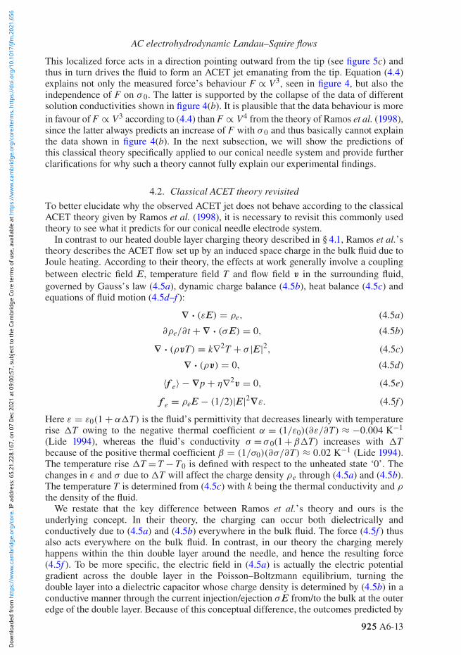
This localized force acts in a direction pointing outward from the tip (see figure 5c) andthus in turn drives the fluid to form an ACET jet emanating from the tip. Equation (4.4)explains not only the measured force’s behaviour F ∝ V3, seen in figure 4, but also theindependence of F on σ 0. The latter is supported by the collapse of the data of differentsolution conductivities shown in figure 4(b). It is plausible that the data behaviour is morein favour of F ∝ V3 according to (4.4) than F ∝ V4 from the theory of Ramos et al. (1998),since the latter always predicts an increase of F with σ 0 and thus basically cannot explainthe data shown in figure 4(b). In the next subsection, we will show the predictions ofthis classical theory specifically applied to our conical needle system and provide furtherclarifications for why such a theory cannot fully explain our experimental findings.
4.2. Classical ACET theory revisitedTo better elucidate why the observed ACET jet does not behave according to the classicalACET theory given by Ramos et al. (1998), it is necessary to revisit this commonly usedtheory to see what it predicts for our conical needle electrode system.
In contrast to our heated double layer charging theory described in § 4.1, Ramos et al.’stheory describes the ACET flow set up by an induced space charge in the bulk fluid due toJoule heating. According to their theory, the effects at work generally involve a couplingbetween electric field E, temperature field T and flow field v in the surrounding fluid,governed by Gauss’s law (4.5a), dynamic charge balance (4.5b), heat balance (4.5c) andequations of fluid motion (4.5d–f ):
∇ · (εE) = ρe, (4.5a)
∂ρe/∂t + ∇ · (σE) = 0, (4.5b)
∇ · (ρvT) = k∇2T + σ |E|2, (4.5c)
∇ · (ρv) = 0, (4.5d)
〈f e〉 − ∇p + η∇2v = 0, (4.5e)
f e = ρeE − (1/2)|E|2∇ε. (4.5f )
Here ε = ε0(1 + αT) is the fluid’s permittivity that decreases linearly with temperaturerise T owing to the negative thermal coefficient α = (1/ε0)(∂ε/∂T) ≈ −0.004 K−1
(Lide 1994), whereas the fluid’s conductivity σ = σ 0(1 + βT) increases with Tbecause of the positive thermal coefficient β = (1/σ0)(∂σ/∂T) ≈ 0.02 K−1 (Lide 1994).The temperature rise T = T − T0 is defined with respect to the unheated state ‘0’. Thechanges in ε and σ due to T will affect the charge density ρe through (4.5a) and (4.5b).The temperature T is determined from (4.5c) with k being the thermal conductivity and ρ
the density of the fluid.We restate that the key difference between Ramos et al.’s theory and ours is the
underlying concept. In their theory, the charging can occur both dielectrically andconductively due to (4.5a) and (4.5b) everywhere in the bulk fluid. The force (4.5f ) thusalso acts everywhere on the bulk fluid. In contrast, in our theory the charging merelyhappens within the thin double layer around the needle, and hence the resulting force(4.5f ). To be more specific, the electric field in (4.5a) is actually the electric potentialgradient across the double layer in the Poisson–Boltzmann equilibrium, turning thedouble layer into a dielectric capacitor whose charge density is determined by (4.5b) in aconductive manner through the current injection/ejection σE from/to the bulk at the outeredge of the double layer. Because of this conceptual difference, the outcomes predicted by
925 A6-13
Dow
nloa
ded
from
htt
ps://
ww
w.c
ambr
idge
.org
/cor
e. IP
add
ress
: 65.
21.2
28.1
67, o
n 07
Dec
202
1 at
09:
00:5
7, s
ubje
ct to
the
Cam
brid
ge C
ore
term
s of
use
, ava
ilabl
e at
htt
ps://
ww
w.c
ambr
idge
.org
/cor
e/te
rms.
htt
ps://
doi.o
rg/1
0.10
17/jf
m.2
021.
656

J.-A. Chen, T. Miloh, W. Kaveevivitchai and H.-H. Wei
these two theories will exhibit completely different dependences on the variables involved.In this subsection, we will employ Ramos et al.’s theory to describe the ACET around aconical needle. The focus here will be the use of this theory to demonstrate how the electricforce density f e in (4.5f ) varies with T and E so as to reveal how the fluid responds tothe time-averaged force density 〈f e〉 according to (4.5d) and (4.5e).
According to Ramos et al. (1998), because T is typically small and so are thepermittivity and conductivity variations ε and σ , the following assumptions can bemade to simplify (4.5a–f ): (i) variations of other fluid properties ρ, η and k due to T arenegligible; (ii) the electric field due to induced charges is much weaker than the appliedelectric field; (iii) the transport of mobile ions are influenced by their electromigrationfluxes much stronger than diffusive and convective fluxes; and (iv) convective heat transferis negligibly small. Since the density variation ρ is negligible according to (i), the fluidcan be deemed virtually incompressible with ∇·v = 0 from (4.5d). For the same reason,buoyancy and natural convection effects are not significant. Thus, (ii) allows a linearizationof (4.5a–c) and (4.5f ) with E coming mainly from the applied electric field. Together with(iii), how induced charges are built up with respect to time can then be determined solelyby the injection/ejection of the electric current σE, as described by (4.5b). Assumption(iv) implies that Joule heat generation is mainly dissipated by conduction (with constant kbecause of (i)) in (4.5c).
Using the above assumptions, Ramos et al. (1998) were able to come up with thefollowing general formula for the electrothermal force density:
f e = ε0(α − β)
1 + iωτDebye(∇T · E)E − 1
2ε0α|E|2∇T, (4.6)
where τDebye = ε0/σ0 represents the Debye relaxation time. Since (4.6) can be applied toany electrode geometries, the precise behaviours of ∇T and E that determine the behaviourof f e will also be geometry dependent. Ramos et al. (1998) used (4.6) to analyse ACETflows on planar electrodes. Here we extend the analysis for a conical needle to see how theneedle geometry influences the features of ACET.
4.3. Outer ACET around a conical needleWe first look at the region sufficiently away from the tip such that the electric field aroundthe needle at a distance r = (z2 + R2)1/2 to the tip behaves like the electric field generatedby a line charge (see figure 6a), where the cylindrical coordinates z and R denote theaxial and radial positions, respectively. Thus, one can employ the slender-body theory(Batchelor 1970) to describe the electric potential distribution Φ(z,R) around the needle as
Φ(z, R) = 14πε
∫ L
0
q(s) ds
[(z − s)2 + R2]1/2 , (4.7)
where q(z) is the unknown charge distribution (per unit length) along the needle of lengthL. For R � L, the integral in (4.7) can be approximated as q(z) ln[4z(L − z)/R2]. WithΦ = Vext denoting the potential exerted on the needle surface R = b(z), we find
q(z) ≈ 4πεVext[L(z)]−1, (4.8)
where L(z) = ln[4z(L − z)/b2(z)]. Following Batchelor (1970), we combine (4.7)and (4.8) to determine both the radial field ER = −∂Φ/∂R and the axial field
925 A6-14
Dow
nloa
ded
from
htt
ps://
ww
w.c
ambr
idge
.org
/cor
e. IP
add
ress
: 65.
21.2
28.1
67, o
n 07
Dec
202
1 at
09:
00:5
7, s
ubje
ct to
the
Cam
brid
ge C
ore
term
s of
use
, ava
ilabl
e at
htt
ps://
ww
w.c
ambr
idge
.org
/cor
e/te
rms.
htt
ps://
doi.o
rg/1
0.10
17/jf
m.2
021.
656

AC electrohydrodynamic Landau–Squire flows
+V
Cold
Hot
R
z
∇RT < 0
(a)
(b)
Figure 6. Schematic illustrations of how the electric field and temperature behave around the needle in theouter region sufficiently away from the tip. Their behaviours are the prerequisites of the use of the theory ofRamos et al. (1998) in explaining the ACET around a conical needle. (a) The electric field around the needleacts in a direction virtually perpendicular to the needle surface, as if the needle were a line charge. (b) Theconical geometry always makes the needle hotter than the fluid. Joule heating effects by the needle or/and bythe fluid will then create an outward temperature gradient dissipating heat into the fluid. The situation looks asif there is a line heat source placed along the central line of the needle.
Ez = −∂Φ/∂z as
ER ≈ 2Vext
R[L(z)]−1, Ez ≈ 0. (4.9a,b)
As the electric field given above essentially resembles that of a line source, we mayconclude that the temperature gradient ∇T in (4.6) is mainly due to its radial component∇RT.
Next, we consider the linearized heat conduction equation (4.5c) subject to Jouleheating:
k∇2T + σ0|E|2 = 0. (4.10)
Similar to the study on a Joule-heated slender conic nanopore (Pan et al. 2016), slenderbody theory implies that ∂/∂R � ∂/∂z and thus the conduction term in (4.10) is dominatedby the radial part k∇2T ≈ kR−1∂[R∂T/∂R]/∂R. Together with σ0|E|2 ≈ σ0E2
R, we solve(4.10) in the approximate form: kR−1∂[R∂T/∂R]/∂R + σ0E2
R = 0 with the boundarycondition T = Tw at R = b(z). Thus the temperature distribution around the needle surfacecan be determined as
T(R, b(z)) = Tw − TEX
2
(ln
Rb
)2
− TIN ln(
Rb
). (4.11)
Here TEX and TIN represent the effective temperatures respectively for external Jouleheating by the fluid and for internal Joule heating by the needle, defined as
TEX = 4(σ0/k)[Vext/L(z)]2, (4.12)
TIN = −b(∂T/∂R)R=b. (4.13)
925 A6-15
Dow
nloa
ded
from
htt
ps://
ww
w.c
ambr
idge
.org
/cor
e. IP
add
ress
: 65.
21.2
28.1
67, o
n 07
Dec
202
1 at
09:
00:5
7, s
ubje
ct to
the
Cam
brid
ge C
ore
term
s of
use
, ava
ilabl
e at
htt
ps://
ww
w.c
ambr
idge
.org
/cor
e/te
rms.
htt
ps://
doi.o
rg/1
0.10
17/jf
m.2
021.
656

J.-A. Chen, T. Miloh, W. Kaveevivitchai and H.-H. Wei
Note that TIN defined by (4.13) is essentially T given by (4.2) because kTIN /b = hT onthe conical surface. Also because of (4.2) and of h ≈ k/b, TIN ≈ T ∝ V2
ext/b2 grows aswe move toward the tip. Thus, (4.11) indicates that the needle is always hotter than thesurrounding fluid with a radial temperature gradient given by
∇RT = −TEX
Rln
(Rb
)− TIN
R. (4.14)
It is also worth noting that the needle geometry always makes ∇RT < 0 point outward andvary like 1/R, regardless of the amount of Joule heating generated from the needle or fromthe fluid. This excessive heat will be eventually dissipated into the fluid that is graduallycooled off with moving away from the needle. The situation looks as if there was a lineardistribution of heat sources placed along the central line of the needle, as illustrated infigure 6(b).
To identify which heating mechanism dominates, we use the following temperature ratioto reflect the importance of external heating compared with internal heating:
G = TEX/TIN . (4.15)
Since TIN ∝ V2ext/b2, G is proportional to b2, which indicates that external heating will be
gradually diminished as the tip is approached and the internal heating will become moreimportant. This may explain why the temperature rise in our experiment mainly arisesfrom the heating by the slender needle, as conjectured by (4.2).
Prior to examining how each heating mechanism impacts the flow, we first providethe proper scaling for the flow field v driven by a given local electric force density f e.Let fe = |f e| be the strength of the force density. Since the electric field mainly actsperpendicular to the needle surface in view of (4.9), it drives the fluid with the radialvelocity uR ∼ feR2/η and axial velocity uz ∼ −uR(z/R) ∼ −fezR/η due to the fluid’scontinuity ∇·v = 0 from (4.5d), namely,
(uR,, uz) ∼ fe(R2, −zR)/η. (4.16)
If G � 1, the heating is dominated by the needle with ∇RT ≈ −T/R ∝ 1/z2R.Together with ER ∼ Vext/R according to (4.9a,b), we have fe ∝ 1/z2R3 from (4.6). Since∇RT < 0, the electric force f e will be acting outward if it is generated by conductivitygradients, i.e. through the β term in (4.6). As this force will be pulling the fluid in the radialdirection and is becoming stronger as the tip is approached, an axial fluid entrainment fromthe thicker end of the needle toward the tip will concurrently be established to fulfil therequirement of fluid continuity. Following (4.16), the resulting fluid velocities behave as
(uR, uz) ∝ (1/z2R, −1/zR2). (4.17)
This indicates that both radial pulling and axial entrainment effects are getting strongeras the tip is approached, thereby producing a vortical flow sweeping toward the tip, asillustrated in figure 7(a). Because of the axisymmetric needle geometry assumed here, theresulting vortical flow should appear as a single toroidal vortex.
However, for G � 1 external Joule heating (4.14) results in ∇RT = −(TEX/R)ln(R/b) < 0 which varies roughly as 1/R but slowly increases in magnitude as approachingtoward the tip (due to the ln(R/b) term). The electric force density f e in (4.6) thereforevaries roughly as 1/R3 due to ER ∝ 1/R in (4.9a,b). Again, if f e is mainly sustained
925 A6-16
Dow
nloa
ded
from
htt
ps://
ww
w.c
ambr
idge
.org
/cor
e. IP
add
ress
: 65.
21.2
28.1
67, o
n 07
Dec
202
1 at
09:
00:5
7, s
ubje
ct to
the
Cam
brid
ge C
ore
term
s of
use
, ava
ilabl
e at
htt
ps://
ww
w.c
ambr
idge
.org
/cor
e/te
rms.
htt
ps://
doi.o
rg/1
0.10
17/jf
m.2
021.
656

AC electrohydrodynamic Landau–Squire flows
E
E
Cold
Cold
Cold
R
z
fe Hot
Hot
Hotter
Uσ−E
σ+E
+V
+V
(a)
(b)
Figure 7. Schematic illustrations of the use of the theory of Ramos et al. (1998) in explaining the ACETflows in both the outer and inner regions from the needle tip. (a) In the outer region, a fluid entrainment fromthe thicker end of the needle toward the tip can result from the outward temperature gradient, as depicted infigure 6(b). (b) In the inner region, the fluid can be pulled out of the hotspot tip to form a microjet and thusreinforce the outer fluid entrainment toward the tip shown in (a).
by conductivity gradients, it will be acting outward under ∇RT < 0, making the fluidvelocities (4.16) vary according to
(uR, uz) ∝ (1/R, −z/R2). (4.18)
As shown above, either internal or external Joule heating will result in a flow sweepingtoward the tip (figure 7a) due to the conductivity gradients caused by the outwardtemperature gradients ∇RT < 0. But in terms of the fluid velocities, the two cases varywith z at different rates. By comparing (4.17) and (4.18), it can be deduced that the axialvelocity for the internal heating case behaves as uz ∝ 1/zR2, whereas the external heatingcase renders uz ∝ z/R2. The former grows much more rapidly than the latter by a factorof 1/z2 moving toward the tip. This can be understood by recalling that the characteristictemperature due to internal heating varies as TIN ∝ 1/z2 according to (4.13) and (4.2),whereas that due to external heating TEX varies slowly with z in (4.12).
4.4. Inner ACET around a sharp conducting nanotipThe previous section merely describes the features of the outer ACET away from the tip inwhich the needle acts like a line charge with the electric field acting virtually normal to theneedle surface. While this can explain the observed flow sweeping and fluid entrainmenttoward the tip, it cannot explain the ACET jet emanating from the tip with the point-force
925 A6-17
Dow
nloa
ded
from
htt
ps://
ww
w.c
ambr
idge
.org
/cor
e. IP
add
ress
: 65.
21.2
28.1
67, o
n 07
Dec
202
1 at
09:
00:5
7, s
ubje
ct to
the
Cam
brid
ge C
ore
term
s of
use
, ava
ilabl
e at
htt
ps://
ww
w.c
ambr
idge
.org
/cor
e/te
rms.
htt
ps://
doi.o
rg/1
0.10
17/jf
m.2
021.
656

J.-A. Chen, T. Miloh, W. Kaveevivitchai and H.-H. Wei
1/r velocity decay seen in the experiment. So it is necessary to look at what happens in theinner region in the close proximity of the tip. The characteristics in the inner region willbe very distinct from those in the outer region. This is because not only will the electricfield become nearly parallel to the needle, but also the tip geometry will be critical to howthe electric and temperature fields behave around the tip.
In the inner region, we assume that the local electric field E =−∇Φ arises mainly fromthe electric potential Φ imposed by the needle satisfying ∇2Φ = 0, while the temperaturefield is still governed by (4.10). Our objective here is to determine the local electrothermalforce exerted on the fluid by the tip. We will also examine both external Joule heating bythe fluid and internal Joule heating by the needle to see which heating mechanism is morefavourable to driving the observed ACET jet.
According to Jackson (1998), the electric potential Φ and the components of the electricfield E = (Er, Eθ ) around a conical tip can be determined as
Φ = V0(r/r0)1−nP1−n(cos θ), (4.19a)
Er = −(1 − n)(V0/r0)(r/r0)−nP1−n(cos θ), (4.19b)
Eθ = (V0/r0)(r/r0)−n sin θP′
1−n(cos θ). (4.19c)
In the above, V0 represents the electric potential at the tip, scaled as Vext. The prime inthe Legendre function P1−n(x) stands for the derivative with respect to x = cos θ . Recallalso that when the tip’s opening angle 2θ0 is small, the exponent n in (4.19) can beapproximated as (1.2) and hence is close to unity.
4.4.1. External Joule heatingLet us first inspect the scenario driven by external Joule heating by the fluid, where the heattransfer is governed by (4.10). Since the expression for the Joule heat generation σ0(E2
r +E2
θ ) now involves [P1−n(cos θ)]2 and [sin θP′1−n(cos θ)]2 in view of (4.19b) and (4.19c), the
detailed temperature distribution for (4.10) cannot be solved analytically. Nevertheless, wecan take advantage of the fact that the actual electric field near the tip looks nearly radiallystraight toward or out of the tip. Following Miloh (2016), we can restrict our attention tothe near-tip region located along the symmetry axis of the needle. In this region, whereθ is sufficiently close to 0° or 180°, we have the anticipated field behaviour |Er| � |Eθ |according to (4.19). Also given that the exponent n is close to unity, the Joule heatinggeneration in (4.10) combined with (4.19) comes mainly from the radial field Er. Thus,letting σ0|E|2 ≈ σ0E2
r in (4.10) with Er ≈ −(1 − n)(V0/r0)(r/r0)−n from (4.19b), we can
solve (4.10) to obtain the temperature distribution around the tip as
T(r) = Ttip − (1/2)(1 − n)(3 − 2n)−1T∗EX(r/r0)
2(1−n). (4.20)
Here Ttip = T(r ≤ r0) denotes the temperature at the tip and
T∗EX = σ0V2
0/k, (4.21)
is the characteristic temperature scale due to external Joule heating by the fluid. As canbe clearly seen from (4.20), the tip is the hottest point having a diminishing temperaturemoving away from the tip, which imparts a temperature gradient ∇rT < 0 around the tip.If the electrothermal force is mainly sustained by conductivity gradients, the force density
925 A6-18
Dow
nloa
ded
from
htt
ps://
ww
w.c
ambr
idge
.org
/cor
e. IP
add
ress
: 65.
21.2
28.1
67, o
n 07
Dec
202
1 at
09:
00:5
7, s
ubje
ct to
the
Cam
brid
ge C
ore
term
s of
use
, ava
ilabl
e at
htt
ps://
ww
w.c
ambr
idge
.org
/cor
e/te
rms.
htt
ps://
doi.o
rg/1
0.10
17/jf
m.2
021.
656

AC electrohydrodynamic Landau–Squire flows
(4.6) with (4.20) and (4.19b) will be acting outward according to
f e ≈ ε0β(1 − n)4
1 + iωτDebye(3 − 2n)−1(T∗
EX/r0)(V0/r0)2(r/r0)
1−4ner. (4.22)
Carrying out the integral F e = 4π∫
fer2 drer taken over a region from r = r0 to a largevalue r∞(�r0), we find the electrothermal force to be
F e ≈ πε0β
1 + iωτDebye(3 − 2n)−1c[2 ln(2/θ0)]−3T∗
EXV20 er, (4.23)
wherein we use (1 − n) ≈ [2 ln(2/θ0)]−1 because of (1.2) and c = (r∞/r0)4(1−n) − 1.
Because n is close to unity here, the force given by (4.23) varies weakly with r∞ and hencecan be deemed as roughly a constant. It behaves like a point-like force acting outward andhence in turn draws a microjet from the tip.
4.4.2. Internal Joule heatingNext, we consider the case of internal Joule heating by the needle. Recall that this case isrelevant to why the measured ACET speed does not grow with the solution conductivityσ 0, as shown in figure 4(b). In this case, the distributions of the electric field componentsare still given by (4.19b) and (4.19c). The temperature field T(r,θ ) around the tip is nowgoverned by ∇2T = 0. According to (4.2), T ∼ 1/r2 so the appropriate solution shouldtake the following decaying form:
T = T∞ + T∗IN(r0/r)2 cos θ, (4.24)
where T∗IN can be defined by (4.2) at b0 = r0 sin θ0 as
T∗IN = T(b0) = I2
2π2kσneedleb20. (4.25)
As a result, the local temperature field given by (4.24) essentially acts like a potentialdipole cos θ/r2 = z/r3 placed at the tip r = 0 with strength (output) T∗
INr20. Therefore, the
temperature will grow rapidly approaching the tip, turning the tip into a hotspot of size r0(assuming cosθ0 ∼ 1) within which a finite temperature rise T(r = r0) − T∞ = T∗
IN givenby (4.25) can be assumed. Given that the finite-temperature hotspot poses an additionalpoint-like heat source with a temperature distribution (4.24), it may be more appropriateto express the actual temperature distribution around the tip as
T = T∞ + c1T∗IN(r/r0)
−1 + c2T∗IN(r/r0)
−2 cos θ + · · · , (4.26)
where the coefficients c1 and c2 (< c1) are positive to ensure outward heat flows from boththe hotspot and the heated cone.
Substituting (4.19b) in (4.6) by taking P1−n(cos θ) ≈ 1 (since cos θ ∼ 1 near the axis),the resulting radial force density can be evaluated as
f e ≈ ε0β(1 − n)2
1 + iωτDebye(T∗
IN/r0)(V0/r0)2[c1 + 2c2(r0/r) cos θ ](r0/r)2(1+n)er, (4.27)
which indicates that the dominant contribution is the hotspot source term c1(r0/r)2(1+n).This hotspot-induced force density is always acting outward, whereas the heating dipolec2 term can be acting inward when θ > 90°. In fact, the latter force distribution is nearly
925 A6-19
Dow
nloa
ded
from
htt
ps://
ww
w.c
ambr
idge
.org
/cor
e. IP
add
ress
: 65.
21.2
28.1
67, o
n 07
Dec
202
1 at
09:
00:5
7, s
ubje
ct to
the
Cam
brid
ge C
ore
term
s of
use
, ava
ilabl
e at
htt
ps://
ww
w.c
ambr
idge
.org
/cor
e/te
rms.
htt
ps://
doi.o
rg/1
0.10
17/jf
m.2
021.
656

J.-A. Chen, T. Miloh, W. Kaveevivitchai and H.-H. Wei
antisymmetric with respect to the tip (because θ ∈ [θ0, π] with θ0 being usually verysmall) and hence contributes a little inward force (of O(θ2
0 ) smaller than the former) towardthe tip after performing a volume integration for f e.
In a similar manner to (4.23), one can deduce that the electrothermal force generated by(4.27) will be concentrated at the near-tip hotspot of size r0 according to
F e ≈ 4πε0β
1 + iωτDebyec1[2ln(2/θ0)]−2(2n − 1)−1T∗
INV20 er. (4.28)
This relation will again furnish a point-like force to draw and eject the fluid near thetip according to (1.5). Compared with (4.23) with T∗
EX∼10−2 ◦C (according to (4.21) withσ0 ∼ 1 μS cm−1 for deionized water), the force (4.28) due to internal heating with a muchhigher temperature rise T∗
IN∼10 ◦C (according to (4.25)) is much stronger in magnitude bya factor
[2ln(2/θ0)]T∗
INT∗
EX. (4.29)
This force will generally render a much faster fluid ejection from the tip, and hencereinforce the fluid entrainment in the outer region (figure 7a), as illustrated in figure 7(b).
As such, either external or internal Joule heating in the vicinity of the tip can make thetip hotter than the surrounding fluid to furnish a point-like electrothermal force and henceresult in a LS jetting phenomenon exhibiting a point-force velocity (1.5). Given that theratio (4.29) of internal to external heating in the inner region is much greater than unityand so is 1/G in the outer region according to (4.15), we may conclude that internal Jouleheating by the needle will play a more dominant role compared with external Joule heatingby the fluid. Since the former can also cause a much stronger fluid entrainment toward thetip in the outer region behind the tip, this together with the local fluid ejection from thetip in the inner region may qualitatively explain the peculiar ACET flow pattern observednear the tip, as shown in figure 2(a).
Yet, from a quantitative perspective, the present bulk charging model within the classicalframework of Ramos et al. (1998) still predicts the ACET velocity scaling u ∝ V4
according to (4.6), which cannot account for the V3 dependence for the measured fluidspeed U observed in the experiment (see figure 4a). In addition, if the heating is generatedmerely by the bulk fluid, this classical theory predicts that u will at least increase linearlywith the fluid conductivity σ 0 because T∗
EX∝σ0 and 1/τDebye ∝ σ0 in (4.23). Yet theserelations cannot explain why U is not increased by increasing σ 0 (see figure 4b). Therefore,to rationalize these disagreements with the classical theory, not only is a new heatedcapacitive charging model (4.3) proposed, but also the surface heating by the needle (4.1)is taken into account.
5. AC electro-osmotic impinging flow
When lowering the frequency below ωtip, the flow will be reversed to an ACEO that acts toimpinge over the tip. This flow can persist at a frequency as low as another characteristicRC frequency ωspine = (2π)−1(σ0/ε0)(λ0/R0) (ranging from 500 Hz to 5 kHz) based onthe microscopic spine at the sharp end of the needle, where R0 ∼ 5 μm is the base radiusof the spine. The measured force F = 4πηUr in this case is found to vary as V2, like thatin the standard ACEO theory (González et al. 2000), as shown in figure 8(a). Hence, thecharge balance within the double layer having a surface charge density qs can be described
925 A6-20
Dow
nloa
ded
from
htt
ps://
ww
w.c
ambr
idge
.org
/cor
e. IP
add
ress
: 65.
21.2
28.1
67, o
n 07
Dec
202
1 at
09:
00:5
7, s
ubje
ct to
the
Cam
brid
ge C
ore
term
s of
use
, ava
ilabl
e at
htt
ps://
ww
w.c
ambr
idge
.org
/cor
e/te
rms.
htt
ps://
doi.o
rg/1
0.10
17/jf
m.2
021.
656

AC electrohydrodynamic Landau–Squire flows
E
U
– – ––
–
+Vλ0
5 10 15 20 25
10
20
F(pN)
V(Vpp)
210–3M NaCl(aq)
DI water
Fe
(a)
(b)
Figure 8. (a) Plot of the measured force F = 4πηUr against the applied voltage V for AC electro-osmoticimpinging flow in deionized water (at 80 kHz) and 1 mM NaCl solution (at 100 kHz), which shows F ∝V2. Multiple data points at a given value of V are the data points taken from different values of r shown infigure 3(b). (b) Illustration of the flow mechanism, driven by an electric force within the double layer.
by the common capacitive model charged by the normal current (González et al. 2000):
∂qs/∂t = σ0E⊥, (5.1)
which yields qs ∼ ω−1σ0E⊥. For a conical region of length �(�λ0) near the tip(figure 8b), the electric force Fe ∼ ∫
qsE//b dr ∝ V2 ln(�/λ0) varies weakly with �, thusproducing a point-force-like flow around the tip with U ∝ 1/r, in contrast to U ∝ 1/r2 ora much faster velocity decay for typical ACEO vortices generated by planar electrodes. Inaddition, we notice in figure 9 that while most of the flow is driven by ACEO, a tiny ACETjetting may still exist in the proximity of the tip, which takes the form of a mass plumeejecting from the tip. A reasonable explanation for this phenomenon may be connected toour finding that the force driving an ACET jet is more concentrated at the tip comparedwith the force driving ACEO. Therefore, as the tip is approached, it is more likely that anACET jet discharging from the tip will be observed. Such a fluid ejection due to ACET issimilar to a jet flow emerging from an open conical nanopipette due to a pressure forcingconcentrated at the tip (Secchi et al. 2017).
925 A6-21
Dow
nloa
ded
from
htt
ps://
ww
w.c
ambr
idge
.org
/cor
e. IP
add
ress
: 65.
21.2
28.1
67, o
n 07
Dec
202
1 at
09:
00:5
7, s
ubje
ct to
the
Cam
brid
ge C
ore
term
s of
use
, ava
ilabl
e at
htt
ps://
ww
w.c
ambr
idge
.org
/cor
e/te
rms.
htt
ps://
doi.o
rg/1
0.10
17/jf
m.2
021.
656

J.-A. Chen, T. Miloh, W. Kaveevivitchai and H.-H. Wei
100 µm
Figure 9. While the flow is dominated by AC electro-osmotic impinging flow over the tip, a mass plume(illuminated by fluorescence-tagged DNA) can sometimes be ejected from the tip, incited by the local ACelectrothermal jetting.
6. AC Faradaic streaming
At frequencies lower than ωspine, especially near the inverse of the time scale associatedwith the charge transfer from the Faradaic electrode reaction, Faradaic leakage currents canbe substantially enhanced by the applied field to cause a coion buildup within the doublelayer. Such an effect reverses the ACEO impinging flow to an ACFS jet emanating from thetip. We find that the measured point-force F = 4πηUr appears to vary at rates ranging fromV2 to V4, as shown in figure 10(a). Olesen et al. (2006) showed in their analysis for planarelectrodes that the ACFS velocity can vary as (logV)2 when V exceeds the thermal voltagekBT/e = 25 mV. Their result was obtained by using the standard normal charging modelin which the Faradaic leakage current is balanced by the Ohmic current in the directionnormal to the electrode surface. Replotting the data by plotting F/logV against logV infigure 10(b), we find that the measured point force F also seems to vary quadratically withlogV. However, because of the slender needle geometry, the Faradaic charging over thesharp tip may be mainly sustained by the tangential current, as illustrated in figure 11(a).Below we propose an alternative model to account for this tangential Faradaic charging.
First of all, the tangential current can be modelled as KsE///� in terms of surfaceconductance Ks ≈ 4λ0σ sinh2(ζ/4kBT) (Lyklema 1995) and the size � of the chargingzone near the tip, wherein ζ is the zeta potential across the Debye diffuse layer and kBT isthe thermal energy. This current sustains the Faradaic current density jF leaked from theneedle surface:
KsE///� ∼ jF. (6.1)
Here we model jF by the following Bulter–Volmer equation (with the transfer coefficientα = 1/2) for the one-step, one-electron redox process (Olesen et al. 2006):
jF = j0 e−eς/2kBT2 sinh[
eφ
2kBT
], (6.2)
where j0 denotes the characteristic exchange current.Secondly, an occurrence of Faradaic reaction is typically realized at relatively
high potentials, i.e. e|φ|/kBT � 1 within the Stern layer (of thickness λs) adjacentto the electrode surface. Therefore, the potential drop φ ≈ qStern/Cs is mainly
925 A6-22
Dow
nloa
ded
from
htt
ps://
ww
w.c
ambr
idge
.org
/cor
e. IP
add
ress
: 65.
21.2
28.1
67, o
n 07
Dec
202
1 at
09:
00:5
7, s
ubje
ct to
the
Cam
brid
ge C
ore
term
s of
use
, ava
ilabl
e at
htt
ps://
ww
w.c
ambr
idge
.org
/cor
e/te
rms.
htt
ps://
doi.o
rg/1
0.10
17/jf
m.2
021.
656

AC electrohydrodynamic Landau–Squire flows
100
200
300
4
2
F(pN)
10–3M NaCl(aq)
DI water
F/lo
g(V
)
(pN
/log V
pp)
F/lo
g(V
)
(pN
/log V
pp)
V (Vpp)
10
50
100
150
200
3/2
50
0
100
150
200
15 20 25
10 15 20 25
10 15 20 25
(a)
(b)
(c)
Figure 10. (a) Plot of the measured force F = 4πηUr against the applied voltage V for AC Faradaic jetting byreplotting the data in figure 3(c) for deionized water (at 100 Hz) and 1 mM NaCl solution (at 1 kHz). Multipledata points at a given value of V are the data points taken from different values of r shown in figure 3(c). Theresult shows that F seems to vary between V2 and V4. (b) Presenting the data by plotting F/log(V) againstlog(V) shows that F varies roughly quadratically with log(V), as indicated by the dashed-line linear fit. (c) Areplot of (b) by plotting F/log(V) against V in a log–log plot, which shows that the data can also behave asF/ log(V) ∝ V3/2.
taking place across the Stern layer with a capacitance Cs = ε0/λs. Using chargeconservation qStern = −qDebye and assuming that the surface charge density qDebye =−(ε0/λ0)(2kBT/e) sinh(eζ/2kBT) within the Debye layer can be described by the classicalGouy–Chapman–Stern model (Lyklema 1995), we obtain
eφ/kBT ≈ δexp(eζ/2kBT). (6.3)
925 A6-23
Dow
nloa
ded
from
htt
ps://
ww
w.c
ambr
idge
.org
/cor
e. IP
add
ress
: 65.
21.2
28.1
67, o
n 07
Dec
202
1 at
09:
00:5
7, s
ubje
ct to
the
Cam
brid
ge C
ore
term
s of
use
, ava
ilabl
e at
htt
ps://
ww
w.c
ambr
idge
.org
/cor
e/te
rms.
htt
ps://
doi.o
rg/1
0.10
17/jf
m.2
021.
656

J.-A. Chen, T. Miloh, W. Kaveevivitchai and H.-H. Wei
E
+V
+V
E
U
λ0
jF
j+//
j –//
Fe
�∗
(a)
(b)
Figure 11. (a) Charging mechanism for AC Faradaic jetting, involving a balance of Faradaic leakage totangential conduction. (b) The resulting electric force tends to drive the fluid away from the tip, thus producinga jet-like streaming.
Equation (6.3) holds for a large positive value of eζ/kBT on the anode, where δ = λs/λ0is the thickness ratio of the Stern layer to the Debye layer. Next, substituting (6.2) into(6.1) with (6.3) for the ζ term and recognizing that eφ/2kBT � ln(eφ/kBT) foreφ/kBT � 1, we can approximately express φ in terms of E// as a Tafel-like equation:
φ ∼ 2(kBT/e) ln[KsE///�δj0]. (6.4)
Since E// ∼ V/� at a distance � from the tip, (6.4) indicates that the Faradaic currentwill become stronger with increasing |φ| as the tip is approached, thereby setting upa violent ACFS jet emitting from the needle tip, as illustrated in figure 11(b). Given thateφ/kBT � 1 in (6.4), the Faradaic charging will be also confined within a near-tip regionof size � much smaller than the critical value
�∗ ∼ (KsV/j0δ)1/2, (6.5)
beyond which the Faradaic reaction will no longer be sustained by the applied electricfield. It follows then that the electric force Fe ∼ qStern�
∗2E// ∼ qStern�∗V over that region
is practically localized near the conical tip. With qStern ≈ −Csφ ∝ log V taken from(6.4), Fe is found to vary with V according to
Fe ∝ V3/2 log V. (6.6)
Figure 10(c) is a replot of figure 10(b) to depict how F/logV varies with V on a logarithmicscale. While either (logV)2 or (6.6) can roughly capture the data trend, the data seem tobe more in favour of (6.6), especially in the high-V regime where the local tangentialFaradaic charging is more prevalent than the normal Faradaic charging to generate theLS-like streaming observed in figure 2(c).
925 A6-24
Dow
nloa
ded
from
htt
ps://
ww
w.c
ambr
idge
.org
/cor
e. IP
add
ress
: 65.
21.2
28.1
67, o
n 07
Dec
202
1 at
09:
00:5
7, s
ubje
ct to
the
Cam
brid
ge C
ore
term
s of
use
, ava
ilabl
e at
htt
ps://
ww
w.c
ambr
idge
.org
/cor
e/te
rms.
htt
ps://
doi.o
rg/1
0.10
17/jf
m.2
021.
656

AC electrohydrodynamic Landau–Squire flows
AC electrothermal jetAC electro-osmotic
impinging flow AC faradaic streaming
Frequency range ω > ωtip ωspine < ω < ωtip ω < ωspineCharging mechanism Tangential double layer
charging to the hotspottip due to internal Jouleheating
Normal chargingwithin the Debyediffuse layer
Tangential Faradaiccharging within theStern layer
Voltage dependence V3 V2 V3/2 log V
Table 1. Summary of the physical features of the three AC Landau–Squire flows observed in theexperiments. The occurrences of these flows are separated by two characteristic RC frequencies: ωtip =(2π)−1(σ0/ε0)(λ0/b0) based on the nanoscale tip, and ωspine = (2π)−1(σ0/ε0)(λ0/R0) based on themicroscale spine at the front end of the needle, which characterize the high- and low-frequency regimes,respectively.
7. Concluding remarks
In conclusion, utilizing the locally diverging electric field prevailing around a sharpconducting nanotip, we discover a new class of Landau–Squire-type flows that can berealized in a purely electrohydrodynamic manner under the actions of ambient AC electricfields. We identify that the flow fields can display the signature of a point-force-like 1/rdecay, as in the classical pressure discharge Landau–Squire flow. But unlike the latter,these AC flows are distinct and can behave rather differently, depending on the specificAC forcing mechanisms. We find that a jet-like streaming from the needle tip can beformed due to local Joule heating effects or to Faradaic reactions. Such a jet-like flowpattern can be also reversed into an impinging flow over the tip as a result of the inducedAC electro-osmotic flow. In the former case, in particular, the measured fluid velocitiesfor the AC electrothermal jet and the AC Faradaic streaming can display distinctivedependences on the applied voltage due to the conical needle geometry, very differentfrom those observed when using planar electrodes. Yet another distinctive feature of theseAC Landau–Squire flows is that they can be manipulated by the applied AC frequencyω according to two characteristic frequencies: ωtip based on the nanoscale tip and ωspinebased on the microscale spine at the sharp end of the needle. The former controls theoccurrence of an AC electrothermal jet whereas the latter determines the reversal of ACelectro-osmotic impinging flow to AC Faradaic streaming. Since these two frequencies arecontrolled by the nanoscopic and microscopic length scales of the needle and are wellseparated, one may be able to design the needle geometry to tailor the frequency ranges ofthese AC flows. Table 1 summarizes these findings, which indicates that a conical electrodegeometry may fundamentally change the main features of AC Landau–Squire flows in thesense that tangential charging might play a more dominant role than normal charging thatcommonly rules in common planar electrode systems. Similar characteristic changes dueto a conical geometry can also affect the ionic transport within a conical nanopore, whichexhibits nonlinear current responses to the applied pressure (Jubin et al. 2018).
It is also worth mentioning that the new AC Landau–Squire-type flow patterns reportedhere are distinct from those observed around nearly insulated dielectric corners (Thamida& Chang 2002; Zehavi & Yossifon 2014; Zehavi, Boymelgreen & Yossifon 2016).The main differences are probably related to distinctive polarization mechanisms – thelatter’s flows are mostly triggered by dielectric polarization whereas the present ones arepredominantly driven by conductive polarization. As for the reported AC electrothermal
925 A6-25
Dow
nloa
ded
from
htt
ps://
ww
w.c
ambr
idge
.org
/cor
e. IP
add
ress
: 65.
21.2
28.1
67, o
n 07
Dec
202
1 at
09:
00:5
7, s
ubje
ct to
the
Cam
brid
ge C
ore
term
s of
use
, ava
ilabl
e at
htt
ps://
ww
w.c
ambr
idge
.org
/cor
e/te
rms.
htt
ps://
doi.o
rg/1
0.10
17/jf
m.2
021.
656

J.-A. Chen, T. Miloh, W. Kaveevivitchai and H.-H. Wei
jet, we find that it cannot be satisfactorily explained by using the fluid Joule heating modelof Ramos et al. (1998). Instead, it can be reasonably accounted for by incorporating thelocal Joule heating inside the needle in conjunction with the familiar capacitive chargingmodel within the double layer. This implies that even in the case of planar electrodes,such a local heating effect might play a role in regions near electrode corners or edgesand hence give rise to a possible enhancement of local electrothermal ejection. As such ajet-like streaming can also be triggered by a Faradaic reaction within the Stern layer on theneedle surface, the features of these jet flows may also be sensitive to the surface conditionsof the tip, depending on the material used or detailed procedures for preparing the tip. Wehave done some tests and found that using different etching conditions or plasma exposuretimes may change these jet flows both qualitatively and quantitatively. How these factorsimpact the features of such flows would require more systematic investigations, which willbe tackled in our future study.
From a technological perspective, as the present various nanotip-based ACLandau–Squire flows can be precisely controlled by the applied AC voltage and frequency,they could be well utilized to expedite fluid pumping or sample mixing in microfluidicdevices. Since the nanotip itself can also be employed to trap nanosized substances, itis possible to turn such a tip into a molecular sensor like that in an ECSTM probe. Thenewly reported AC flows may be able to facilitate the capture of selected target moleculesand hence improve the detection capability in such applications. Our study is also quiterelevant to the use of an atomic force microscopy tip in promoting trapping and assemblyof molecules or nanoparticles under ambient AC electric fields (Freedman et al. 2016;Zhou et al. 2017). With the aid of the amplified electric field near the tip, such a processis commonly achieved using DEP. Since AC Landau–Squire flows can also be present atthe same time, one may be able to utilize these flows to enhance the DEP trapping at thetip. The reason is that convective effects by such flows are typically long-range because ofthe slow 1/r decay in velocity. Therefore, samples in the bulk fluid can be rapidly broughttoward the tip, increasing their chance to be captured by the tip through DEP.
Acknowledgements. We thank Prof Y.-L. Lee and C.-C. Liu for their assistance with the drop-offelectrochemical etching technique for making sharp tungsten tips. We also would like to thank T.-I. Lin andC.-Y. Chen for helping with the preparation and revision of the figures.
Funding. This work is supported by the Ministry of Science and Technology of Taiwan under the grants107-2221-E-006-109-MY3 and 110-2221-E-006-021-MY3 of H.-H.W.
Declaration of interests. The authors report no conflict of interest.
Author ORCIDs.Hsien-Hung Wei https://orcid.org/0000-0002-8608-0296.
REFERENCES
BATCHELOR, G.K. 1970 Slender-body theory for particles of arbitrary cross-section in Stokes flow. J. FluidMech. 44, 419–440.
BINNIG, G. & ROHRER, H. 1987 Scanning tunneling microscopy from birth to adolescence. Rev. Mod. Phys.59, 615–625.
CROWLEY, J.M. 1977 Role of Joule heating in the electrostatic spraying of liquids. J. Appl. Phys. 48, 145–147.FREEDMAN, K.J., OTTO, L.M., IVANOV, A.P., BARIK, A., OH, S.-H. & EDEL, J.B. 2016 Nanopore sensing
at ultra-low concentrations using single-molecule dielectrophoretic trapping. Nat. Commun. 7, 10217.GAGNON, Z.R. & CHANG, H.-C. 2009 Electrothermal AC electro-osmosis. Appl. Phys. Lett. 94, 024101.GAÑÁN-CALVO, A.M., LÓPEZ-HERRERA, J.M., HERRADA, M.A., RAMOS, A. & MONTANERO, J.M.
2018 Review on the physics of electrospray: from electrokinetics to the operating conditions of single andcoaxial Taylor cone-jets, and AC electrospray. J. Aerosol Sci. 125, 32–56.
925 A6-26
Dow
nloa
ded
from
htt
ps://
ww
w.c
ambr
idge
.org
/cor
e. IP
add
ress
: 65.
21.2
28.1
67, o
n 07
Dec
202
1 at
09:
00:5
7, s
ubje
ct to
the
Cam
brid
ge C
ore
term
s of
use
, ava
ilabl
e at
htt
ps://
ww
w.c
ambr
idge
.org
/cor
e/te
rms.
htt
ps://
doi.o
rg/1
0.10
17/jf
m.2
021.
656

AC electrohydrodynamic Landau–Squire flows
GARCÍA-SÁNCHEZ, P., RAMOS, A. & GONZÁLEZ, A. 2011 Effects of Faradaic currents on AC electroosmoticflows with coplanar symmetric electrodes. Colloids Surf. A: Physicochem. Engng Aspects 376, 47–52.
GONZÁLEZ, A., RAMOS, A., GREEN, N.G., CASTELLANOS, A. & MORGAN, H. 2000 Fluid flow inducedby nonuniform AC electric fields in electrolytes on microelectrodes. II. A linear double-layer analysis. Phys.Rev. E 61, 4019–4028.
GREEN, N.G., RAMOS, A., GONZÁLEZ, A., CASTELLANOS, A. & MORGAN, H. 2001 Electrothermallyinduced fluid flow on micro-electrodes. J. Electrost. 53, 71–87.
IBE, J.P., BEY, P.P., BRANDOW, S.L., BRIZZOLARA, R.A., BURNHAM, N.A., DILELLA, D.P., LEE, K.P.,MARRIAN, C.R.K. & COLTON, R.J. 1990 On the electrochemical etching of tips for scanning tunnelingmicroscopy. J. Vac. Sci. Technol. A 8, 3570–3575.
ITAYA, K. & TOMITA, E. 1988 Scanning tunneling microscope for electrochemistry - a new concept for the insitu scanning tunneling microscope in electrolyte solutions. Surface Sci. 201, L507–L512.
JACKSON, J.D. 1998 Classical Electrodynamics. Wiley.JUBIN, L., POGGIOLI, A., SIRIA, A. & BOCQUET, L. 2018 Dramatic pressure-sensitive ion conduction in
conical nanopores. Proc. Natl Acad. Sci. USA 115, 4063–4068.KIM, S. & KARRILA, S.J. 1991 Microhydrodynamics: Principles and Selected Applications. Butterworth-
Heinemann.LAN, W.-J., EDWARDS, M.A., LUO, L., PERERA, R.T., WU, X., MARTIN, C.R. & WHITE, H.S. 2016
Voltage-rectified current and fluid flow in conical nanopores. Acc. Chem. Res. 49, 2605–2613.LANDAU, L.D. & LIFSHITZ, E.M. 1959 Fluid Mechanics Vol.6 of Course of Theoretical Physics. Pergamon
Press.LAOHAKUNAKORN, N., GOLLNICK, B., MORENO-HERRERO, F., AARTS, D.G.A.L., DULLENS, R.P.A.,
GHOSAL, S. & KEYSER, U.F. 2013 A Landau–Squire nanojet. Nano Lett. 13, 5141–5146.LIDE, D.R. 1994 CRC Handbook of Chemistry and Physics, 74th ed. CRC.LYKLEMA, J. 1995 Fundamentals of Interface and Colloid Science, vol. II. Academic Press.MILOH, T. 2016 Opto-electro-fluidics and tip coax conical surface plasmons. Phys. Rev. Fluids 1, 044105.MORGAN, H. & GREEN, N.G. 2003 AC Electrokinetics: Colloids and Nanoparticles. Research Studies Press
Ltd.OLESEN, L.H., BRUUS, H. & AJDARI, A. 2006 AC electrokinetic micropumps: the effect of geometrical
confinement, Faradaic current injection, and nonlinear surface capacitance. Phys. Rev. E 73, 056313.PAN, Z., WANG, C., LI, M. & CHANG, H.-C. 2016 Universal scaling of robust thermal hot spot and ionic
current enhancement. Phys. Rev. Lett. 117, 134301.RAMOS, A., MORGAN, H., GREEN, N.G. & CASTELLANOS, A. 1998 AC electrokinetics: a review of forces
in microelectrode structures. J. Phys. D: Appl. Phys. 31, 2338–2353.RAMOS, A., MORGAN, H., GREEN, N.G. & CASTELLANOS, A. 1999 AC electric-field-induced fluid flow in
microelectrodes. J. Colloid Interface Sci. 217, 420–422.SECCHI, E., MARBACH, S., NIGUÈS, A., SIRIA, A. & BOCQUET, L. 2017 The Landau–Squire plume.
J. Fluid Mech. 826, R3.SECCHI, E., MARBACH, S., NIGUÈS, A., STEIN, D., SIRIA, A. & BOCQUET, L. 2016 Massive
radius-dependent flow slippage in carbon nanotubes. Nature 537, 210–213.SIN, M.L., GAU, V., LIAO, J.C. & WONG, P.K. 2010 Electrothermal fluid manipulation of high-conductivity
samples for laboratory automation applications. J. Lab. Autom. 15, 426–432.SQUIRE, H.B. 1951 The round laminar jet. Q. J. Mech. Appl. Maths 4, 321–329.THAMIDA, S.K. & CHANG, H.-C. 2002 Nonlinear electrokinetic ejection and entrainment due to polarization
at nearly wedges. Phys. Fluids 14, 4315–4328.WU, X., RAJASEKARAN, P.R. & MARTIN, R. 2016 An alternating current electroosmotic pump based on
conical nanopore membranes. ACS Nano 10, 4637–4643.ZEHAVI, M., BOYMELGREEN, A. & YOSSIFON, G. 2016 Competition between induced-charge
electro-osmosis and electrothermal effects at low frequencies around a weakly polarizable microchannelcorner. Phys. Rev. Appl. 5, 044013.
ZEHAVI, M. & YOSSIFON, G. 2014 Particle dynamics and rapid trapping in electro-osmotic flow around asharp micro-channel corner. Phys. Fluids 26, 082002.
ZHOU, P., YU, H., YANG, W., WEN, Y., WANG, Z., LI, W.J. & LIU, L. 2017 Spatial manipulation andassembly of nanoparticles by atomic force microscopy tip-induced dielectrophoresis. ACS Appl. Mater.Interfaces 9, 16715–16724.
925 A6-27
Dow
nloa
ded
from
htt
ps://
ww
w.c
ambr
idge
.org
/cor
e. IP
add
ress
: 65.
21.2
28.1
67, o
n 07
Dec
202
1 at
09:
00:5
7, s
ubje
ct to
the
Cam
brid
ge C
ore
term
s of
use
, ava
ilabl
e at
htt
ps://
ww
w.c
ambr
idge
.org
/cor
e/te
rms.
htt
ps://
doi.o
rg/1
0.10
17/jf
m.2
021.
656