ac-f4x and ac-g4x family manual - abk lock & safe information ac-f4x and ac-g4x family manual...
TRANSCRIPT
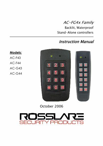
AC-FG4x Family Backlit, Waterproof
Stand-Alone controllers
Instruction Manual
Models: AC-F43 AC-F44 AC-G43 AC-G44
October 2006

Table of Contents
AC-F4x and AC-G4x Family Manual Page ii
Table of Contents 1. General Information ..................................................................... 4
1.1 INTRODUCTION ............................................................................... 4 1.2 CONTROLLER TYPES...................................................................... 4 1.3 BOX CONTENT ................................................................................. 5 1.4 ANCILLARY EQUIPMENT .............................................................. 5 1.5 TECHNICAL SPECIFICATIONS...................................................... 6 1.6 KEY FEATURES ................................................................................ 7 1.7 FRONT PANEL DESCRIPTION ....................................................... 8
2. Installation ..................................................................................... 9 2.1 MOUNTING THE CONTROLLER ................................................... 9 2.2 WIRING THE CONTROLLER ........................................................ 10
3. Operation ..................................................................................... 14 3.1 MODES OF OPERATION................................................................ 14 3.1.1 Normal Mode (Default) ................................................................. 14 3.1.2 Secure Mode .................................................................................. 14 3.1.3 Bypass Mode.................................................................................. 15 3.2 USER LEVELS ................................................................................. 15 3.2.1 Normal User................................................................................... 15 3.2.2 Secure User .................................................................................... 16 3.2.3 Master User .................................................................................... 16 3.3 SWITCHING OPERATIONAL MODES......................................... 16 3.3.1 From Normal to Secure Mode ....................................................... 16 3.3.2 From Secure to Normal Mode ....................................................... 17 3.3.3 From Normal to Bypass Mode....................................................... 17 3.3.4 From Bypass to Normal Mode....................................................... 18 3.4 SPECIAL OPERATIONAL FEATURES......................................... 18 3.4.1 Auxiliary Input & Output............................................................... 18 3.4.2 Request to Exit Button (REX) ....................................................... 18 3.4.3 Tamper Feature .............................................................................. 19 3.4.4 Lockout Feature (Keypad / Card Tamper)..................................... 19 3.4.5 BL-D40 External Sounder ............................................................. 20
Table of Contents
AC-F4x and AC-G4x Family Manual Page iii
4. Programming............................................................................... 21 4.1 INTRODUCTION ............................................................................. 21 4.1.1 Entering the Programming Mode .................................................. 23 4.1.2 Exiting the Programming Mode .................................................... 23 4.2 CHANGING THE OPEN CODE...................................................... 24 4.3 CHANGING THE AUXILIARY CODE .......................................... 24 4.4 CHANGING THE PROGRAMMING CODE.................................. 25 4.5 CHANGING THE NORMAL/SECURE CODE .............................. 26 4.6 CHANGING THE NORMAL/BYPASS CODE............................... 26 4.7 SETTING FAILSAFE/SECURE OPERATION............................... 27 4.8 SETTING AUXILIARY MODES .................................................... 28 4.8.1 General ........................................................................................... 28 4.8.2 Quick Reference Guide for Auxiliary Mode Setting..................... 30 4.8.3 Detailed Reference Guide .............................................................. 31 4.9 SETTING THE LOCKOUT FEATURE........................................... 36 4.10 BACKLIGHT and LED BEHAVIOR ............................................... 37 4.11 ENROLLING CODES ...................................................................... 37 4.11.1 Primary Codes Definition .............................................................. 37 4.11.2 Secondary Codes Definition .......................................................... 38 4.11.3 Primary and Secondary Codes Enrolling Methods........................ 38 4.11.4 Standard Method for Codes Enrolling ........................................... 39 4.11.5 Search Method for Codes Enrolling .............................................. 40 4.12 DELETING CODES.......................................................................... 40 4.12.1 Standard Method for Deleting Codes ............................................ 41 4.12.2 Search Method for Deleting Codes................................................ 41 4.13 RELAY CODES ASSIGNMENT ..................................................... 43 4.13.1 Relay Code Assignment using Standard Method .......................... 43 4.13.2 Relay Code Assignment using Search Method ............................. 44 4.14 PIN CODE LENGTH / FACTORY DEFAULT SETTINGS........... 45 4.15 REPLACING A PROGRAMMING CODE...................................... 46 4.16 REPLACING A NORMAL/SECURE CODE .................................. 46
Appendix A. Limited Warranty.................................................. 47 Appendix B. Technical Support.................................................. 49
General Information
AC-F4x and AC-G4x Family Manual Page 4
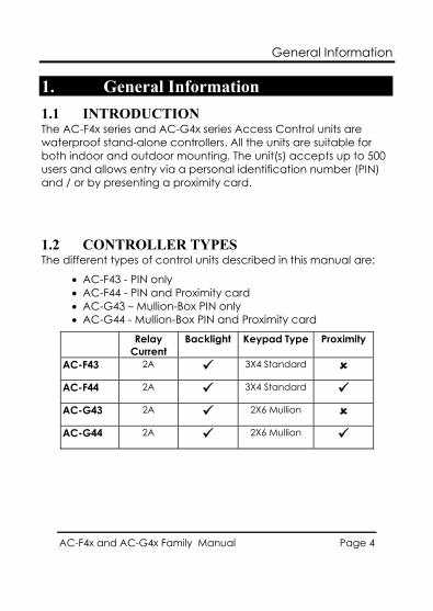
1. General Information 1.1 INTRODUCTION The AC-F4x series and AC-G4x series Access Control units are waterproof stand-alone controllers. All the units are suitable for both indoor and outdoor mounting. The unit(s) accepts up to 500 users and allows entry via a personal identification number (PIN) and / or by presenting a proximity card.
1.2 CONTROLLER TYPES The different types of control units described in this manual are:
• AC-F43 - PIN only • AC-F44 - PIN and Proximity card • AC-G43 – Mullion-Box PIN only • AC-G44 - Mullion-Box PIN and Proximity card
Relay Current
Backlight Keypad Type Proximity
AC-F43 2A 3X4 Standard AC-F44 2A 3X4 Standard AC-G43 2A 2X6 Mullion AC-G44 2A 2X6 Mullion
General Information
AC-F4x and AC-G4x Family Manual Page 5
1.3 BOX CONTENT Before beginning verify that all of the following is in the box, if anything is missing please report the discrepancy to your nearest Rosslare Office.
• One unit • One Drilling Template (Label/Sticker) • One security spline key • One security hex screw • Four mounting screws and wall plugs
1.4 ANCILLARY EQUIPMENT The following ancillary equipment may be required to complete your installation:
• Electric Lock Strike Mechanism - fail safe (power to lock) or fail secure (power to open).
• Power Supply with Backup Battery - 12 to 24 VDC (from a regulated power supply) or 16 to 24 VAC (from a transformer).
• Request to Exit (REX) Button (optional) - normally open type; switch is closed when pressed.
• BL-D40 External Sounder (optional) - provides siren, bell, and chime.
• Magnetic Contact (optional) - installed for door monitor capabilities.
Other Rosslare accessories can be found at Rosslare's Web Site:
www.rosslaresecurity.com

General Information
AC-F4x and AC-G4x Family Manual Page 6
1.5 TECHNICAL SPECIFICATIONS AC-F43 AC-F44 AC-G43 AC-G44
VDC 12-24 V DC Input Voltage
VAC 16-24 V AC
Maximum Input Current (12VDC) 125mA 160mA 125mA 160mA
Standby Input Current (12VDC) 75mA 95mA 75mA 95mA
Maximum Relay Current 2A
REX Input Normally Open (Dry Contact)
Aux. Input Normally Open (Dry Contact)
Max. Proximity read range N/A 75 mm (2.95") N/A 80 mm (3.15")
Proximity Modulation N/A ASK at125 KHz N/A ASK at 125 KHz
Proximity card compatibility N/A 26 Bits EM cards N/A 26 Bits EM cards
LED Indicators Two 3 colored LED (Mode and Door)
Operating Temperatures -22° F to 150° F (-30° C to 65° C)
Operating humidity 0 to 95% (Non-Condensing)
Outdoor Usage Weather resistant, meets IP-65, Epoxy potted
Size H4.72" x W2.80" x D1.17" H120.9 x W71.1 x D29.7 mm
H5.33" x W1.74" x D1.12" H135.4 x W44.2 x D28.5 mm
Weight 0.54 lbs (244g) 0.39 lbs (178g)
General Information
AC-F4x and AC-G4x Family Manual Page 7
1.6 KEY FEATURES • 500 Users • Water resistant • Programmable Backlight and active LED control • Three user levels: normal; secure; master • Three modes of operation: normal; bypass; secure • Integrated keypad for PIN entry • Integrated proximity card reader (F44 and G44 only) • Selectable PIN code length up to 8 digits • Auxiliary input and auxiliary output • Ten auxiliary modes including: door ajar; forced door;
shunt; door monitor; normal / secure; LED control • Input for Request to Exit (REX) button • Code search feature for easy maintenance of user codes • Internal buzzer • Vandal proof screw (special tool supplied) • Two tri-color LED indicators for status / programming
Interface • Built-in case and back tamper protection • Lockout feature on wrong entries (Keypad / Card Tamper) • Bell, chime, siren and strobe features available with BL-D40 • Programmable siren time (with BL-D40) • Programmable lock strike release time. • Supplied with mounting template for easy installation
General Information
AC-F4x and AC-G4x Family Manual Page 8
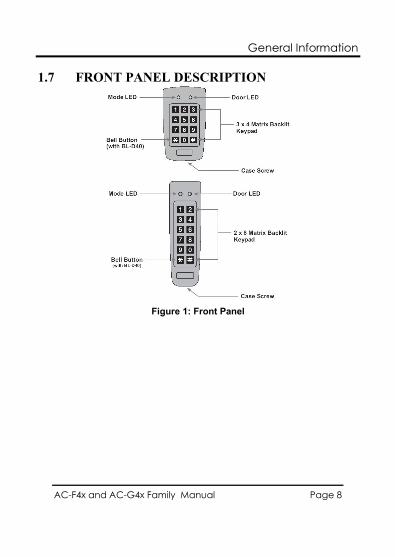
1.7 FRONT PANEL DESCRIPTION
Figure 1: Front Panel
Installation
AC-F4x and AC-G4x Family Manual Page 9
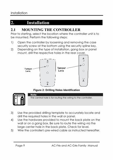
2. Installation 2.1 MOUNTING THE CONTROLLER Prior to starting, select the location where the controller unit is to be mounted. Perform the following steps:
1) Open the controller by loosening and removing the case security screw at the bottom using the security spline key.
2) Depending on the type of installation, gang box or panel mount, drill the respective holes in the rear cover.
Figure 2: Drilling Holes Identification
Note: The central hole is for routing the wiring to the controller.
3) Use the provided drilling template to accurately locate and drill the required holes in the wall or panel.
4) Use the hardware provided to mount the back plate on the wall or on a gang box. Be sure to route the wiring via the large center hole in the back plate. Check for level.
5) Wire the controller's pre-wired cable as instructed hereafter.
Installation
AC-F4x and AC-G4x Family Manual Page 10
6) Once wired, replace the controller back onto its back plate and secure using tamper-proof screw and special tool, supplied with the hardware.
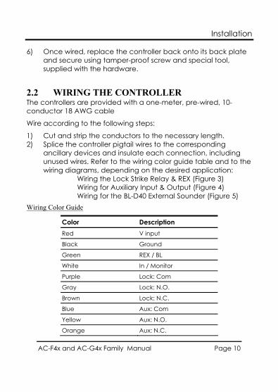
2.2 WIRING THE CONTROLLER The controllers are provided with a one-meter, pre-wired, 10-conductor 18 AWG cable
Wire according to the following steps:
1) Cut and strip the conductors to the necessary length. 2) Splice the controller pigtail wires to the corresponding
ancillary devices and insulate each connection, including unused wires. Refer to the wiring color guide table and to the wiring diagrams, depending on the desired application:
Wiring the Lock Strike Relay & REX (Figure 3) Wiring for Auxiliary Input & Output (Figure 4) Wiring for the BL-D40 External Sounder (Figure 5)
Wiring Color Guide
Color Description Red V input
Black Ground
Green REX / BL
White In / Monitor
Purple Lock: Com
Gray Lock: N.O.
Brown Lock: N.C.
Blue Aux: Com
Yellow Aux: N.O.
Orange Aux: N.C.
Installation
AC-F4x and AC-G4x Family Manual Page 11
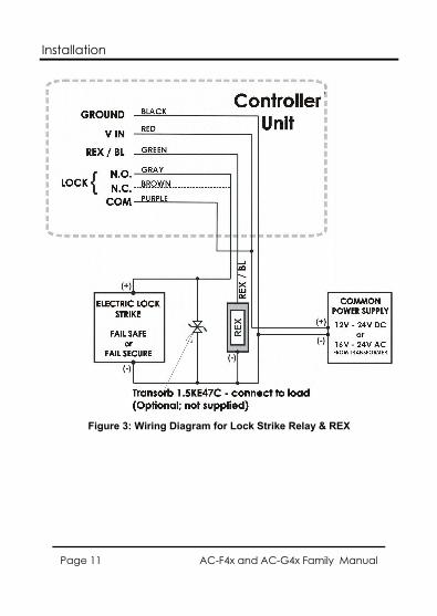
Figure 3: Wiring Diagram for Lock Strike Relay & REX
Installation
AC-F4x and AC-G4x Family Manual Page 12
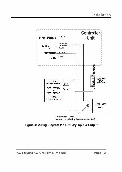
Figure 4: Wiring Diagram for Auxiliary Input & Output
Installation
AC-F4x and AC-G4x Family Manual Page 13
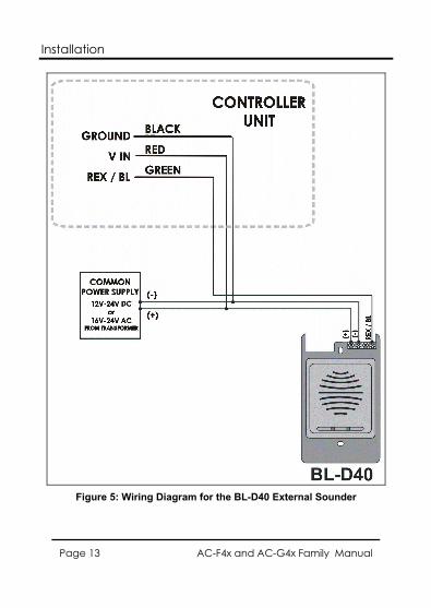
Figure 5: Wiring Diagram for the BL-D40 External Sounder
Operation
AC-F4x and AC-G4x Family Manual Page 14
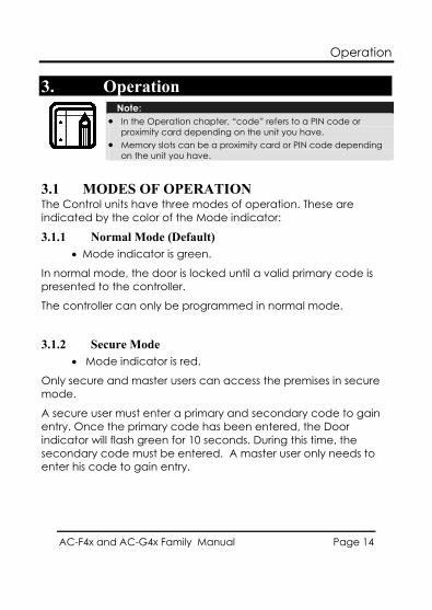
3. Operation
Note: • In the Operation chapter, “code” refers to a PIN code or
proximity card depending on the unit you have. • Memory slots can be a proximity card or PIN code depending
on the unit you have.
3.1 MODES OF OPERATION The Control units have three modes of operation. These are indicated by the color of the Mode indicator:
3.1.1 Normal Mode (Default) • Mode indicator is green.
In normal mode, the door is locked until a valid primary code is presented to the controller.
The controller can only be programmed in normal mode.
3.1.2 Secure Mode • Mode indicator is red.
Only secure and master users can access the premises in secure mode.
A secure user must enter a primary and secondary code to gain entry. Once the primary code has been entered, the Door indicator will flash green for 10 seconds. During this time, the secondary code must be entered. A master user only needs to enter his code to gain entry.
Operation
AC-F4x and AC-G4x Family Manual Page 15
3.1.3 Bypass Mode • Mode indicator is orange.
In bypass mode, access to the premises is dependent on the Lock Strike relays; that is, if the relay is programmed for failsafe operation or fail-secure operation.
When the Lock Strike relay is programmed for fail secure operation, the door is locked until the star button ( ) is depressed.
When the Lock Strike relay is programmed for failsafe operation, the door is constantly unlocked.
In case of power failure, once the power is restored, the controller will return to normal mode, for security reasons.
3.2 USER LEVELS The AC-F4x and AC-G4x series Access Control units accept up to 500 users and provide entry via the use of codes. Each user is allocated two memory slots: Memory Slot 1 (primary code) and Memory Slot 2 (secondary code).
The way in which the two memory slots are programmed, determines a user’s access level. It also establishes what access is granted for each of the three modes of operation.
There are three user levels:
3.2.1 Normal User A normal user only has a primary code and is granted access only when the controller is in its normal or bypass mode.
Operation
AC-F4x and AC-G4x Family Manual Page 16
3.2.2 Secure User A secure user must have a primary and secondary code assigned, and the two codes must not be the same. The secure user can gain access in any mode of operation. In normal mode the secure user must use the primary code to gain entry. In secure mode, the secure user must first enter the primary and then the secondary code, in order to gain entry.
3.2.3 Master User A master user must have identical primary and secondary codes assigned. The codes are entered with the same proximity card or the same PIN. The master user can gain access during any mode of operation by entering their code only once.
3.3 SWITCHING OPERATIONAL MODES The three modes of operation defined above, can be changed with a few simple steps.
3.3.1 From Normal to Secure Mode The default factory setting for the normal / secure code is 3838.
1) Enter the normal / secure code • Mode indicator will flash red
2) Depress the # key to confirm the Mode change. • Mode indicator is red.
The auxiliary input of the controller can also be used to switch the mode of operation from secure to normal and vice versa, if the auxiliary input is selected it de-activates the Norma/Secure mode code. Refer to Setting the Auxiliary Mode, paragraph 4.8.
Mode Door Red
Mode Door Green
Mode Door Red
Operation
AC-F4x and AC-G4x Family Manual Page 17
3.3.2 From Secure to Normal Mode The default factory setting for the normal / secure code is 3838.
1) Enter the normal / secure code. • Mode indicator will flash green.
2) Depress the # key to confirm the Mode change. • Mode indicator will turn green.
The auxiliary input of the controller can also be used to switch the mode of operation from secure to normal and vice versa, if the auxiliary input is selected it de-activates the Norma/Secure mode code. Refer to Setting the Auxiliary Mode, paragraph 4.8.
3.3.3 From Normal to Bypass Mode By default, there is no normal / bypass code. The normal / bypass code must first be programmed to use this function. Refer to paragraph 4.6 to create / modify the normal / bypass code.
1) Enter the normal / bypass code.
• Mode indicator will flash orange.
2) Depress the # key to confirm the mode change. • Mode indicator will turn orange.
Mode Door Red
Mode Door Green
Mode Door Green
Mode Door Green
Mode Door
Orange
Mode Door Orange
Operation
AC-F4x and AC-G4x Family Manual Page 18
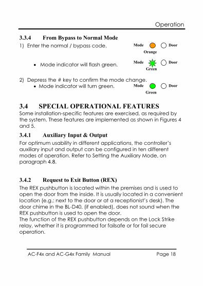
3.3.4 From Bypass to Normal Mode 1) Enter the normal / bypass code.
• Mode indicator will flash green.
2) Depress the # key to confirm the mode change. • Mode indicator will turn green.
3.4 SPECIAL OPERATIONAL FEATURES Some installation-specific features are exercised, as required by the system. These features are implemented as shown in Figures 4 and 5.
3.4.1 Auxiliary Input & Output For optimum usability in different applications, the controller’s auxiliary input and output can be configured in ten different modes of operation. Refer to Setting the Auxiliary Mode, on paragraph 4.8.
3.4.2 Request to Exit Button (REX) The REX pushbutton is located within the premises and is used to open the door from the inside. It is usually located in a convenient location (e.g.: next to the door or at a receptionist’s desk). The door chime in the BL-D40, (if enabled), does not sound when the REX pushbutton is used to open the door. The function of the REX pushbutton depends on the Lock Strike relay, whether it is programmed for failsafe or for fail secure operation.
Mode Door
Orange
Mode Door Green
Mode Door Green
Operation
AC-F4x and AC-G4x Family Manual Page 19
Fail Secure Operation: from the moment the REX pushbutton is depressed, the door will be unlocked until the Lock Strike release time has elapsed. After this time, the door will be locked, even if the REX pushbutton has not been released.
Failsafe Operation: from the moment the REX pushbutton is depressed, the door will be unlocked until the REX pushbutton is released. In this case, the Lock Strike relay only begins its countdown once the REX pushbutton has been released. This feature is designed to keep the door open, when used in conjunction with fire systems.
3.4.3 Tamper Feature In case the controller is forcibly opened or the controller is removed from the wall, a tamper event is triggered. A tamper signal is sent to the BL-D40.
If the BL-D40 External Sounder receives a tamper event signal, it will activate a tamper output and a strobe light. The siren time can be easily programmed in the controller from 0 to 9 minutes.
The tamper event can activate the auxiliary output if the controller is in Auxiliary Mode 3. Refer to the Quick Reference Guide for Auxiliary Mode Setting table in paragraph 4.8.2 below.
3.4.4 Lockout Feature (Keypad / Card Tamper) In case the controller is presented with wrong codes, (PIN or Card) consecutively several times the unit goes into lockout mode.
When a lockout occurs, the controller's keypad and card reader are de-activated so no codes can be entered until the preset lockout period expires.
During Lockout, Mode LED is Off, Door LED flashes Red, and the controller beeps every two seconds.
Refer to programming menu 6 for detailed programming of this feature.
Operation
AC-F4x and AC-G4x Family Manual Page 20
3.4.5 BL-D40 External Sounder The BL-D40 External Sounder is designed for indoor use only and installed within the secured premises. The Sounder can be powered by a 12 to 24 VDC power supply or by a 16VAC transformer. The BL-D40 is capable of emitting four different types of audible and visual alerts: bell, chime, siren and strobe light.
• The bell sounds when the controller’s bell button is depressed.
• The door chime can be programmed to sound whenever a valid code is entered as well as for a door held open alert.
• The siren can be programmed to sound when the controller is tampered with (opened or removed from the wall). The length of the siren can also be programmed in the controller.
The controller communicates with the BL-D40 via a Rosslare proprietary protocol. If the BL-D40 receives an unrecognized code over its communication line or communications between the controller and the BL-D40 are severed, the strobe will flash repeatedly, until the communication problem has been resolved.
Programming
AC-F4x and AC-G4x Family Manual Page 21
4. Programming
Note: • In the Programming chapter, “code” refers to a PIN code or
proximity card depending on the unit you have. • When entering a PIN or presenting a proximity card is
mentioned, the meaning may vary between units.
4.1 INTRODUCTION Programming the Access Control unit is done solely via the unit’s keypad-driven Programming Menu System. To reach the Programming Menu System, the controller must first be placed into Programming Mode. Refer to Entering Programming Mode, paragraph 4.1.1
During the manufacturing process, certain codes and settings are pre-programmed. These settings are the called default factory settings.
Programming
AC-F4x and AC-G4x Family Manual Page 22
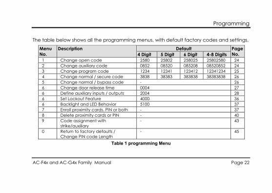
The table below shows all the programming menus, with default factory codes and settings.
Default Menu No.
Description 4 Digit 5 Digit 6 Digit 4-8 Digits
Page No.
1 Change open code 2580 25802 258025 25802580 24 2 Change auxiliary code 0852 08520 085208 08520852 24 3 Change program code 1234 12341 123412 12341234 25 4 Change normal / secure code 3838 38383 383838 38383838 26 5 Change normal / bypass code - 26 6 Change door release time 0004 27 6 Define auxiliary inputs / outputs 2004 28 6 Set Lockout Feature 4000 36 6 Backlight and LED Behavior 5100 37 7 Enroll proximity cards, PIN or both - 37 8 Delete proximity cards or PIN - 40 9 Code assignment with
strike/auxiliary - 43
0 Return to factory defaults / Change PIN code Length
- 45
Table 1 programming Menu
Programming
AC-F4x and AC-G4x Family Manual Page 23
Mode Door Red
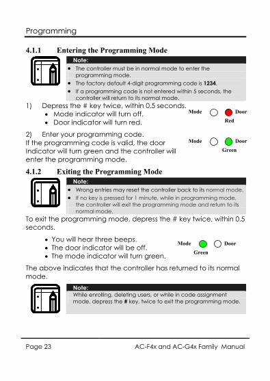
4.1.1 Entering the Programming Mode
Note: • The controller must be in normal mode to enter the
programming mode. • The factory default 4-digit programming code is 1234. • If a programming code is not entered within 5 seconds, the
controller will return to its normal mode. 1) Depress the # key twice, within 0.5 seconds.
• Mode indicator will turn off. • Door indicator will turn red.
2) Enter your programming code. If the programming code is valid, the door Indicator will turn green and the controller will enter the programming mode.
4.1.2 Exiting the Programming Mode
Note: • Wrong entries may reset the controller back to its normal mode. • If no key is pressed for 1 minute, while in programming mode,
the controller will exit the programming mode and return to its normal mode.
To exit the programming mode, depress the # key twice, within 0.5 seconds.
• You will hear three beeps. • The door indicator will be off. • The mode indicator will turn green.
The above indicates that the controller has returned to its normal mode.
Note: While enrolling, deleting users, or while in code assignment mode, depress the # key, twice to exit the programming mode.
Mode Door
Green
Mode Door Green
Programming
AC-F4x and AC-G4x Family Manual Page 24
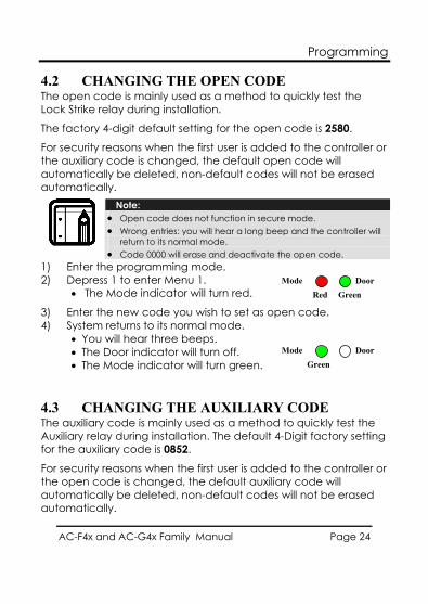
4.2 CHANGING THE OPEN CODE The open code is mainly used as a method to quickly test the Lock Strike relay during installation.
The factory 4-digit default setting for the open code is 2580.
For security reasons when the first user is added to the controller or the auxiliary code is changed, the default open code will automatically be deleted, non-default codes will not be erased automatically.
Note: • Open code does not function in secure mode. • Wrong entries: you will hear a long beep and the controller will
return to its normal mode. • Code 0000 will erase and deactivate the open code.
1) Enter the programming mode. 2) Depress 1 to enter Menu 1.
• The Mode indicator will turn red.
3) Enter the new code you wish to set as open code. 4) System returns to its normal mode.
• You will hear three beeps. • The Door indicator will turn off. • The Mode indicator will turn green.
4.3 CHANGING THE AUXILIARY CODE The auxiliary code is mainly used as a method to quickly test the Auxiliary relay during installation. The default 4-Digit factory setting for the auxiliary code is 0852.
For security reasons when the first user is added to the controller or the open code is changed, the default auxiliary code will automatically be deleted, non-default codes will not be erased automatically.
Mode Door Red Green
Mode Door Green
Programming
AC-F4x and AC-G4x Family Manual Page 25
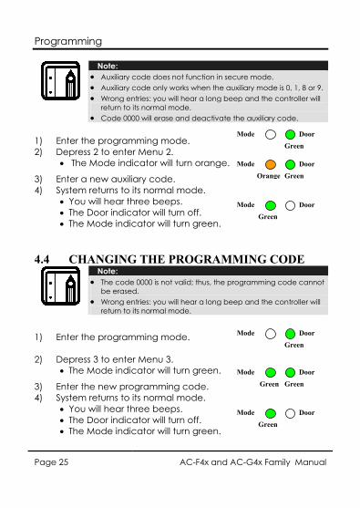
Note: • Auxiliary code does not function in secure mode. • Auxiliary code only works when the auxiliary mode is 0, 1, 8 or 9. • Wrong entries: you will hear a long beep and the controller will
return to its normal mode. • Code 0000 will erase and deactivate the auxiliary code.
1) Enter the programming mode. 2) Depress 2 to enter Menu 2.
• The Mode indicator will turn orange.
3) Enter a new auxiliary code. 4) System returns to its normal mode.
• You will hear three beeps. • The Door indicator will turn off. • The Mode indicator will turn green.
4.4 CHANGING THE PROGRAMMING CODE
Note: • The code 0000 is not valid; thus, the programming code cannot
be erased. • Wrong entries: you will hear a long beep and the controller will
return to its normal mode.
1) Enter the programming mode.
2) Depress 3 to enter Menu 3. • The Mode indicator will turn green.
3) Enter the new programming code. 4) System returns to its normal mode.
• You will hear three beeps. • The Door indicator will turn off. • The Mode indicator will turn green.
Mode Door
Green
Mode Door Orange Green
Mode Door Green
Mode Door
Green
Mode Door Green Green
Mode Door Green
Programming
AC-F4x and AC-G4x Family Manual Page 26
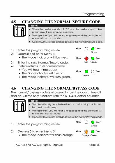
4.5 CHANGING THE NORMAL/SECURE CODE
Note: • When the auxiliary mode is 1, 2, 3 or 4, the auxiliary input takes
priority over the normal/secure code. • Wrong entries: you will hear a long beep and the controller will
return to its normal mode. • Code 0000 will erase and deactivate the normal/secure code.
1) Enter the programming mode. 2) Depress 4 to enter Menu 4.
• The Mode indicator will flash red.
3) Enter the new Normal/Secure code. 4) System returns to its normal mode.
• You will hear three beeps. • The Door indicator will turn off. • The Mode indicator will turn green.
4.6 CHANGING THE NORMAL/BYPASS CODE The normal / bypass code is also used to turn the door chime off and on. Chime only functions with the BL-D40 External Sounder.
Note: • The chime is only heard when the Lock Strike relay is activated
by a valid code entry. • Wrong entries: you will hear a long beep and the controller will
return to its normal mode. • Code 0000 will erase and deactivate the normal/bypass code.
1) Enter the programming mode.
2) Depress 5 to enter Menu 5. • The Mode indicator will flash orange.
Mode Door
Green
Mode Door Red Green
Mode Door Green
Mode Door
Green
Mode Door Orange Green
Programming
AC-F4x and AC-G4x Family Manual Page 27
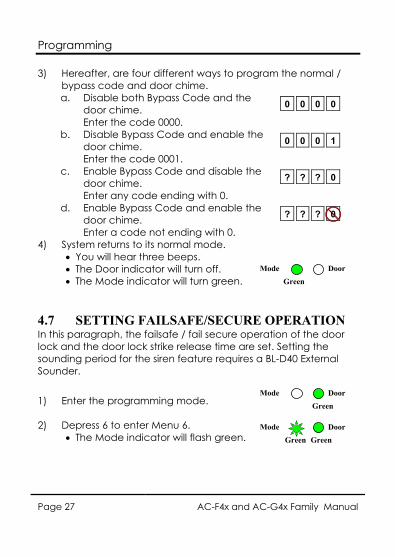
3) Hereafter, are four different ways to program the normal / bypass code and door chime. a. Disable both Bypass Code and the
door chime. Enter the code 0000.
b. Disable Bypass Code and enable the door chime. Enter the code 0001.
c. Enable Bypass Code and disable the door chime. Enter any code ending with 0.
d. Enable Bypass Code and enable the door chime. Enter a code not ending with 0.
4) System returns to its normal mode. • You will hear three beeps. • The Door indicator will turn off. • The Mode indicator will turn green.
4.7 SETTING FAILSAFE/SECURE OPERATION In this paragraph, the failsafe / fail secure operation of the door lock and the door lock strike release time are set. Setting the sounding period for the siren feature requires a BL-D40 External Sounder.
1) Enter the programming mode.
2) Depress 6 to enter Menu 6. • The Mode indicator will flash green.
0 0 0 0
0 0 0 1
? ? ? 0
? ? ? 0
Mode Door Green
Mode Door Green Green
Mode Door
Green
Programming
AC-F4x and AC-G4x Family Manual Page 28
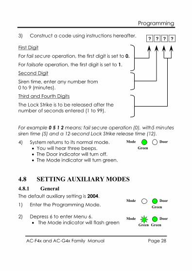
3) Construct a code using instructions hereafter. First Digit
For fail secure operation, the first digit is set to 0. For failsafe operation, the first digit is set to 1.
Second Digit
Siren time, enter any number from 0 to 9 (minutes).
Third and Fourth Digits
The Lock Strike is to be released after the number of seconds entered (1 to 99).
For example 0 5 1 2 means: fail secure operation (0), with5 minutes siren time (5) and a 12-second Lock Strike release time (12).
4) System returns to its normal mode. • You will hear three beeps. • The Door indicator will turn off. • The Mode indicator will turn green.
4.8 SETTING AUXILIARY MODES 4.8.1 General The default auxiliary setting is 2004.
1) Enter the Programming Mode.
2) Depress 6 to enter Menu 6. • The Mode indicator will flash green
? ? ? ?
Mode Door Green
Mode Door Green Green
Mode Door
Green
Programming
AC-F4x and AC-G4x Family Manual Page 29
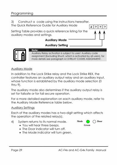
3) Construct a code using the instructions hereafter. The Quick Reference Guide for Auxiliary Mode
Setting Table provides a quick reference listing for the auxiliary modes and settings.
Auxiliary Mode Auxiliary Setting
Note: Auxiliary Relay activation is subject to users' Auxiliary code assignment (Excluding Shunt, which is activated by all users), for more details see paragraph 4.13 RELAY CODES ASSIGNMENT.
Auxiliary Mode
In addition to the Lock Strike relay and the Lock Strike REX, the controller features an auxiliary output relay and an auxiliary input, whose function is established by the auxiliary mode selection (0 thru 9).
The auxiliary mode also determines if the auxiliary output relay is set for failsafe or for fail secure operation.
For a more detailed explanation on each auxiliary mode, refer to the Auxiliary Mode Reference table below.
Auxiliary Settings
Each of the auxiliary modes has a two-digit setting which affects the operation of the related relay(s).
4) System returns to its normal mode. • You will hear three beeps. • The Door indicator will turn off. • The Mode indicator will turn green.
2 ? ? ?
Mode Door
Green
Programming
AC-F4x and AC-G4x Family Manual Page 30
4.8.2 Quick Reference Guide for Auxiliary Mode Setting Auxiliary
Mode Auxiliary Input
Function Auxiliary Output
Activated by
Auxiliary Relay
Auxiliary Settings (in seconds)
0 AUX REX Valid code or AUX REX
N.O. 01 to 99 Aux. relay release time 00 Aux. relay toggle
1 Normal/Secure switch
Valid code N.O. 01 to 99 Aux. relay release time 00 Aux. relay toggle
2 Normal/Secure switch
Star button ( ) N.O. 01 to 99 Aux. relay release time 00 Aux. relay toggle
3 Normal/Secure switch
Tamper event N.C. 01 to 99 Aux. relay release time 00 Aux. relay tamper activated
4 Normal/Secure switch
Direct shunt N.O. 01 to 99 Shunt time
5 Door Monitor Shunt N.C. 01 to 99 Maximum shunt time 6 Door Monitor Forced door N.C. 01 to 99 Forced delay 7 Door Monitor Door ajar N.C. 01 to 99 Ajar delay 8 LED control –
Green Valid code N.O. 01 to 99 Aux. relay release time
00 Aux. relay toggle 9 LED control - Red Valid code N.O. 01 to 99 Aux. relay release time
00 Aux. relay toggle
Programming
AC-F4x and AC-G4x Family Manual Page 31
4.8.3 Detailed Reference Guide The following are brief descriptions of each auxiliary mode. To implement the features of each mode, refer to Setting the Auxiliary Mode, paragraph 4.8.1. AUXILIARY MODE 0
Auxiliary input function: Activates the auxiliary output
Auxiliary output activated by: Valid user code, Auxiliary code, Auxiliary input
E.g. In auxiliary mode 0, the controller can function as a two-door controller. The auxiliary relay is to be attached to the lock on the second door. The auxiliary setting defines the door open time for the second door. The auxiliary input is to be attached to the REX pushbutton for the second door. Door Monitor input feature for the second door is not enabled when using this mode.
AUXILIARY MODE 1
Auxiliary input function: Toggles normal/secure modes
Auxiliary output activated by: Valid user code, Auxiliary code
E.g. In auxiliary mode 1, the controller can function as a two-door controller. The auxiliary relay is to be attached to the lock on the second door. REX feature for the second door is not enabled when using this mode.
The auxiliary setting defines the door open time for the second door. The auxiliary input can switch the mode of operation of the controller between normal and secure mode. By connecting a switch timer or alarm system output to the auxiliary input, the controller can be automatically switched from normal mode (during office hours) to secure mode (after office hours).
Programming
AC-F4x and AC-G4x Family Manual Page 32
AUXILIARY MODE 2
Auxiliary input function: Toggles normal/secure modes
Auxiliary output activated by: Star Button (*)
E.g. In auxiliary mode 2, the auxiliary relay can function as a general purpose time switch that can be activated when the star button ( ) is depressed. The auxiliary setting establishes for how long the auxiliary relay is to be activated. The auxiliary input can switch the mode of operation of the controller between normal and secure mode. By connecting a switch timer or alarm system output to the auxiliary input, the controller can be automatically switched from normal mode (during office hours) to secure mode (after office hours).
AUXILIARY MODE 3
Auxiliary input function: Toggles normal/secure modes
Auxiliary output activated by: Alarms
E.g. In auxiliary mode 3, the auxiliary output is activated if the controller is tampered; that is, if the case is forcibly opened or removed from the wall. The auxiliary input can switch the mode of operation of the controller between normal and secure mode. By connecting a switch timer or alarm system output to the auxiliary input, the controller can be automatically switched from normal mode (during office hours) to secure mode (after office hours).
Programming
AC-F4x and AC-G4x Family Manual Page 33
AUXILIARY MODE 4
Auxiliary input function: Toggles normal/secure modes
Auxiliary output activated by: direct shunt (explanation below)
E.g. In auxiliary mode 4, the controller is capable of bypassing an alarm zone by shunting an alarm system’s door sensor. The auxiliary output is to be wired in parallel to the door sensor output. When in use, the auxiliary output is normally open and the door sensor functions normally. When a valid code is entered, the auxiliary relay shunts the door sensor for the duration of the shunt time, as defined by the auxiliary setting. If the door is left open longer than the shunt time, an alarm will be triggered.
AUXILIARY MODE 5
Auxiliary input function: Door Monitor Auxiliary output activated by: Shunt (explanation below)
E.g. In auxiliary mode 5, the controller is capable of shunting an alarm system. In this mode, the auxiliary input is to be wired to the magnetic contact switch on the door. The auxiliary relay is wired to the alarm system. Without a valid code entered, the auxiliary relay will match the condition of the magnetic contact switch; if the door opens, the auxiliary relay will open; if the door closes, the auxiliary relay will close. When a valid code is entered, a count down for maximum shunt time, as defined by the auxiliary setting, begins; if the door is not closed before the maximum shunt time, the alarm will be triggered.
Programming
AC-F4x and AC-G4x Family Manual Page 34
AUXILIARY MODE 6
Auxiliary input function: Door Monitor Auxiliary output activated by: Forced entry
E.g. In auxiliary mode 6, the controller can trigger the auxiliary relay if the door has been forced. If the Siren Settings is enabled the siren will be activated.
In this mode, the auxiliary input functions as a door monitor switch and is wired to the magnetic contact switch on the door. The auxiliary relay is to be wired to the alarm system. If the door is forced open, the controller will wait for the period of the forced door delay time to elapse and then, it will activate the auxiliary relay. The auxiliary setting sets the forced door delay period.
AUXILIARY MODE 7
Auxiliary input function: Door Monitor Auxiliary output activated by: Door Ajar (door held open)
E.g. In auxiliary mode 7, the controller can trigger the auxiliary relay, if it detects that the door has been held open (ajar) too long. In this mode the auxiliary input functions as a door monitor switch and is wired to the magnetic contact switch on the door. The auxiliary relay is to be wired to the alarm system. If the door is opened, the controller will wait for the door ajar delay time to elapse and if the door does not close prior to the end of this period, the controller will activate the auxiliary relay. The auxiliary setting defines the door-ajar time.
If the BL-D40 External Sounder is connected in the system and a door-ajar event occurs, the BL-D40 will chime every few seconds for 1 minute or until the door is closed.
Programming
AC-F4x and AC-G4x Family Manual Page 35
AUXILIARY MODE 8
Auxiliary input function: Green LED control Auxiliary output activated by: Valid user code, Auxiliary code
E.g. In auxiliary mode 8, the controller can function as a two-door controller and also provide indicator functionality control. The auxiliary relay is connected to the lock on the second door. The auxiliary setting defines the door open time for the second door. The auxiliary input is used to control the Door indicator. If the auxiliary input is open, the indicator will flash green; if the auxiliary input is closed, the Door indicator will flash red.
Note: This mode takes control of the Door indicator LED. The indicator LED will not be lit when: 1. A valid code is entered 2. While in secure mode, when waiting for a secondary code.
AUXILIARY MODE 9
Auxiliary input function: Red LED control Auxiliary output activated by: Valid user code, Auxiliary code
E.g. In auxiliary mode 9, the controller can function as a two-door controller and also provide indicator functionality control. The auxiliary relay is connected to the lock on the second door. The auxiliary setting defines the door open time for the second door. The auxiliary input is used to control the indicator. If the auxiliary input is open the Door indicator will flash red; if the auxiliary input is closed the Door indicator will flash green.
Note: This mode takes control of the Door indicator LED. The indicator LED will not be lit when: 1. A valid code is entered 2. While in secure mode, when waiting for a secondary code.
Programming
AC-F4x and AC-G4x Family Manual Page 36
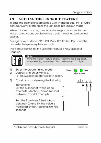
4.9 SETTING THE LOCKOUT FEATURE In case the controller is presented with wrong codes, (PIN or Card) consecutively several times the unit goes into lockout mode.
When a lockout occurs, the controller keypad and reader are locked so no codes can be entered until the set lockout period expires.
During Lockout, Mode LED is Off, Door LED flashes Red, and the controller beeps every two seconds.
The default setting for the Lockout Feature is 4000 (Lockout Disabled)
Note: Using the lockout feature is highly recommended, especially when selecting to use short PIN code length (4 or 5 digits).
1) Enter the programming mode. 2) Depress 6 to enter Menu 6.
• The Mode indicator will flash green.
3) Construct a code using the following
instructions: Set the number of wrong code attempts, which will cause Lockout between 0 and 9 attempts. Sets the Duration of the lockout, between 00 and 99, the value is multiplied by ten, resulting in 0-990 seconds
4 ? ? ?
Mode Door Green Green
Programming
AC-F4x and AC-G4x Family Manual Page 37
4.10 BACKLIGHT and LED BEHAVIOR The controller allows you to define the way the units' Backlight as well as the Mode and Door LEDs will work.
To define the Backlight and LEDs operation:
1) Enter the programming mode. 2) Depress 6 to enter Menu 6.
• The Mode indicator will flash green.
3) Construct a code using the following instructions: the first digit is five indicating the backlight and Led option the second key can be 0-3 indicating the type of activity • Option 0 - LED Active / Backlight Off • Option 1 - LED Active / Backlight On
(default) • Option 2 - LED and Backlight Off, both
activated on any key press for ten seconds. • Option 3 - LED Active / Backlight Dimmed,
backlight activated on any key press for ten seconds.
4.11 ENROLLING CODES 4.11.1 Primary Codes Definition
• Primary codes can only be enrolled to an empty user slot, a slot with no existing primary code in the controller’s memory.
• A primary code must be unique; for instance, one user’s primary code may not be the same as that of another user.
5 ? 0 0
Mode Door Green Green
Programming
AC-F4x and AC-G4x Family Manual Page 38
• Primary codes cannot be the same as system codes, such as the normal / secure code or the open code.
• Users possessing a primary code can gain entry during normal and bypass modes.
4.11.2 Secondary Codes Definition • Secondary codes can only be enrolled to a user slot that
already includes a primary code. • A Secondary code need not be unique; for instance, one
user’s Secondary code may be the same as that of another user.
• Secondary codes cannot be the same as any system codes, such as: the normal / secure code or the open code.
• Users possessing secondary codes can gain entry in any mode of operation.
• A Secondary code can be the same as the primary code of any user.
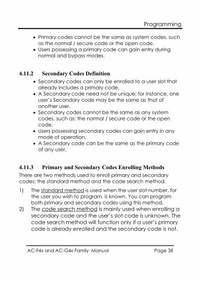
4.11.3 Primary and Secondary Codes Enrolling Methods There are two methods used to enroll primary and secondary codes: the standard method and the code search method.
1) The standard method is used when the user slot number, for the user you wish to program, is known. You can program both primary and secondary codes using this method.
2) The code search method is mainly used when enrolling a secondary code and the user’s slot code is unknown. The code search method will function only if a user’s primary code is already enrolled and the secondary code is not.
Programming
AC-F4x and AC-G4x Family Manual Page 39
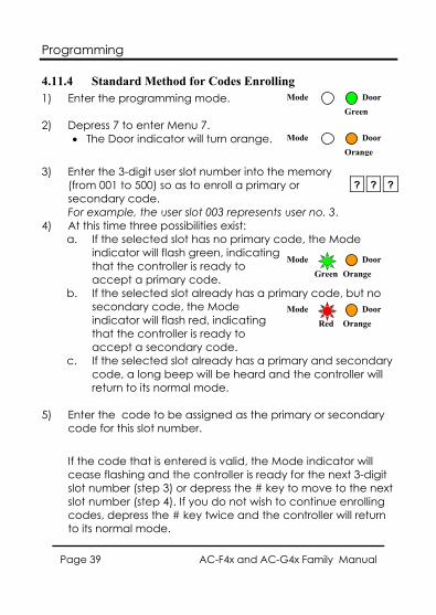
4.11.4 Standard Method for Codes Enrolling 1) Enter the programming mode.
2) Depress 7 to enter Menu 7.
• The Door indicator will turn orange.
3) Enter the 3-digit user slot number into the memory (from 001 to 500) so as to enroll a primary or secondary code. For example, the user slot 003 represents user no. 3.
4) At this time three possibilities exist: a. If the selected slot has no primary code, the Mode
indicator will flash green, indicating that the controller is ready to accept a primary code.
b. If the selected slot already has a primary code, but no secondary code, the Mode indicator will flash red, indicating that the controller is ready to accept a secondary code.
c. If the selected slot already has a primary and secondary code, a long beep will be heard and the controller will return to its normal mode.
5) Enter the code to be assigned as the primary or secondary code for this slot number.
If the code that is entered is valid, the Mode indicator will cease flashing and the controller is ready for the next 3-digit slot number (step 3) or depress the # key to move to the next slot number (step 4). If you do not wish to continue enrolling codes, depress the # key twice and the controller will return to its normal mode.
? ? ?
Mode Door
Green
Mode Door
Orange
Mode Door Green Orange
Mode Door Red Orange
Programming
AC-F4x and AC-G4x Family Manual Page 40
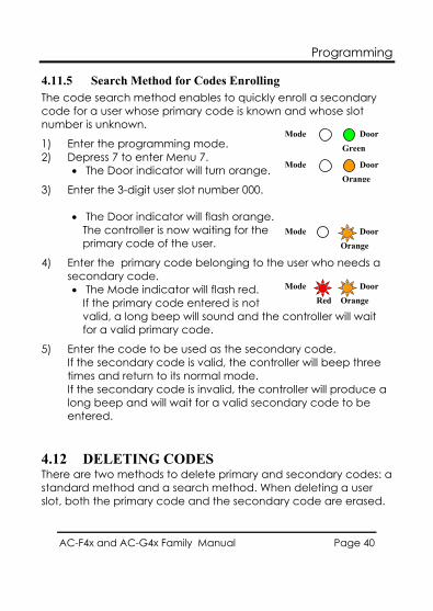
4.11.5 Search Method for Codes Enrolling The code search method enables to quickly enroll a secondary code for a user whose primary code is known and whose slot number is unknown.
1) Enter the programming mode. 2) Depress 7 to enter Menu 7.
• The Door indicator will turn orange.
3) Enter the 3-digit user slot number 000. • The Door indicator will flash orange.
The controller is now waiting for the primary code of the user.
4) Enter the primary code belonging to the user who needs a secondary code. • The Mode indicator will flash red.
If the primary code entered is not valid, a long beep will sound and the controller will wait for a valid primary code.
5) Enter the code to be used as the secondary code. If the secondary code is valid, the controller will beep three times and return to its normal mode. If the secondary code is invalid, the controller will produce a long beep and will wait for a valid secondary code to be entered.
4.12 DELETING CODES There are two methods to delete primary and secondary codes: a standard method and a search method. When deleting a user slot, both the primary code and the secondary code are erased.
Mode Door
Green
Mode Door
Orange
Mode Door
Orange
Mode Door Red Orange
Programming
AC-F4x and AC-G4x Family Manual Page 41
Note: It is recommended that a record be kept of added and deleted users. This makes it easier to keep track of user slots’ status (empty or not)
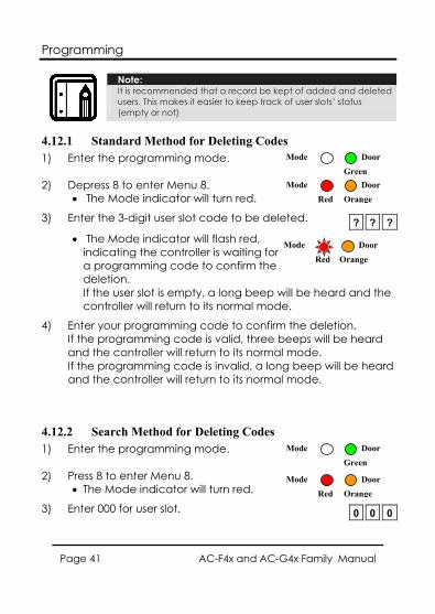
4.12.1 Standard Method for Deleting Codes 1) Enter the programming mode.
2) Depress 8 to enter Menu 8.
• The Mode indicator will turn red.
3) Enter the 3-digit user slot code to be deleted.
• The Mode indicator will flash red, indicating the controller is waiting for a programming code to confirm the deletion. If the user slot is empty, a long beep will be heard and the controller will return to its normal mode.
4) Enter your programming code to confirm the deletion. If the programming code is valid, three beeps will be heard and the controller will return to its normal mode. If the programming code is invalid, a long beep will be heard and the controller will return to its normal mode.
4.12.2 Search Method for Deleting Codes 1) Enter the programming mode.
2) Press 8 to enter Menu 8.
• The Mode indicator will turn red.
3) Enter 000 for user slot.
? ? ?
0 0 0
Mode Door
GreenMode Door
Red Orange
Mode Door Red Orange
Mode Door
Green
Mode Door Red Orange
Programming
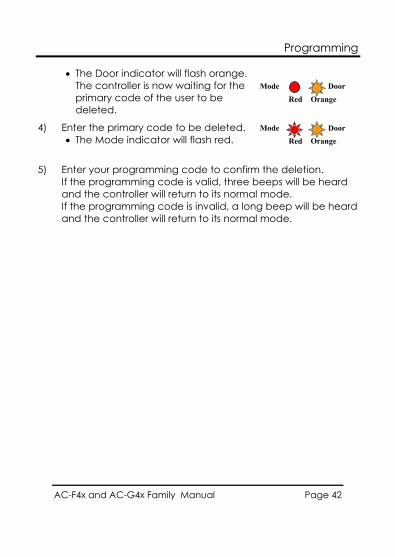
AC-F4x and AC-G4x Family Manual Page 42
• The Door indicator will flash orange. The controller is now waiting for the primary code of the user to be deleted.
4) Enter the primary code to be deleted. • The Mode indicator will flash red.
5) Enter your programming code to confirm the deletion. If the programming code is valid, three beeps will be heard and the controller will return to its normal mode. If the programming code is invalid, a long beep will be heard and the controller will return to its normal mode.
Mode Door Red Orange
Mode Door Red Orange
Programming
AC-F4x and AC-G4x Family Manual Page 43
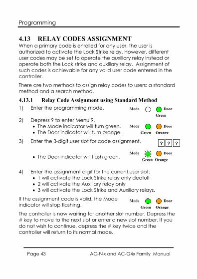
4.13 RELAY CODES ASSIGNMENT When a primary code is enrolled for any user, the user is authorized to activate the Lock Strike relay. However, different user codes may be set to operate the auxiliary relay instead or operate both the Lock strike and auxiliary relay. Assignment of such codes is achievable for any valid user code entered in the controller.
There are two methods to assign relay codes to users: a standard method and a search method.
4.13.1 Relay Code Assignment using Standard Method 1) Enter the programming mode.
2) Depress 9 to enter Menu 9.
• The Mode indicator will turn green. • The Door indicator will turn orange.
3) Enter the 3-digit user slot for code assignment.
• The Door indicator will flash green.
4) Enter the assignment digit for the current user slot: • 1 will activate the Lock Strike relay only deafult • 2 will activate the Auxiliary relay only • 3 will activate the Lock Strike and Auxiliary relays.
If the assignment code is valid, the Mode indicator will stop flashing.
The controller is now waiting for another slot number. Depress the # key to move to the next slot or enter a new slot number. If you do not wish to continue, depress the # key twice and the controller will return to its normal mode.
? ? ?
Mode Door
Green
Mode Door Green Orange
Mode Door Green Orange
Mode Door Green Orange
Programming
AC-F4x and AC-G4x Family Manual Page 44
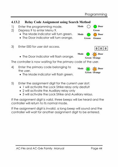
4.13.2 Relay Code Assignment using Search Method 1) Enter the programming mode. 2) Depress 9 to enter Menu 9.
• The Mode indicator will turn green. • The Door indicator will turn orange.
3) Enter 000 for user slot access.
• The Door indicator will flash orange.
The controller is now waiting for the primary code of the user.
4) Enter the primary code belonging to the user. • The Mode indicator will flash green.
5) Enter the assignment digit for the current user slot: • 1 will activate the Lock Strike relay only deafult • 2 will activate the Auxiliary relay only • 3 will activate the Lock Strike and Auxiliary relays.
If the assignment digit is valid, three beeps will be heard and the controller will return to its normal mode.
If the assignment digit is invalid, a long beep will sound and the controller will wait for another assignment digit to be entered.
0 0 0
Mode Door
Green
Mode Door Green Orange
Mode Door Green Orange
Mode Door Green Orange
Programming
AC-F4x and AC-G4x Family Manual Page 45
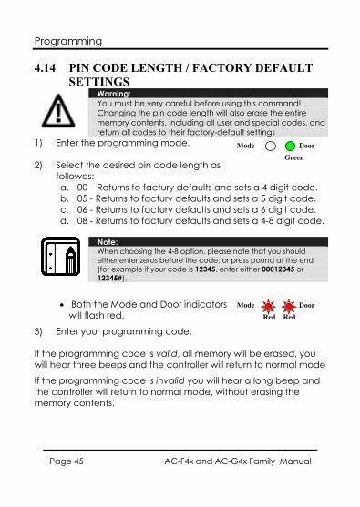
4.14 PIN CODE LENGTH / FACTORY DEFAULT SETTINGS
Warning: You must be very careful before using this command! Changing the pin code length will also erase the entire memory contents, including all user and special codes, and return all codes to their factory-default settings
1) Enter the programming mode.
2) Select the desired pin code length as followes: a. 00 – Returns to factury defaults and sets a 4 digit code. b. 05 - Returns to factury defaults and sets a 5 digit code. c. 06 - Returns to factury defaults and sets a 6 digit code. d. 08 - Returns to factury defaults and sets a 4-8 digit code.
Note: When choosing the 4-8 option, please note that you should either enter zeros before the code, or press pound at the end (for example if your code is 12345, enter either 00012345 or 12345#).
• Both the Mode and Door indicators will flash red.
3) Enter your programming code.
If the programming code is valid, all memory will be erased, you will hear three beeps and the controller will return to normal mode
If the programming code is invalid you will hear a long beep and the controller will return to normal mode, without erasing the memory contents.
Mode Door
Green
Mode Door Red Red
Programming
AC-F4x and AC-G4x Family Manual Page 46
4.15 REPLACING A PROGRAMMING CODE
Note: The controller must be in its normal mode for the procedure to work. Insure that the Mode indicator is green before proceeding.
1) Remove power from the controller. 2) Depress and hold the REX pushbutton. 3) Apply power to the unit with the REX pushbutton depressed. 4) Release the REX pushbutton. 5) You now have 15 seconds to program a new programming
code into the unit using the initial default code, before the controller reverts to the existing code. the deafult code depends on the pin length selected, reffer to the programming Menu table on page 22.
4.16 REPLACING A NORMAL/SECURE CODE
Note: The controller must be in its secure mode for the procedure to work. Insure that the Mode indicator is red before proceeding.
1) Remove power from the controller. 2) Depress and hold the REX pushbutton. 3) Apply power to the unit with the REX pushbutton depressed. 4) Release the REX pushbutton. 5) You now have 15 seconds to use the normal/secure code to
return to the normal mode. Once in the normal mode, enter the programming mode to program a new normal/secure code. the deafult code depends on the pin length selected, reffer to the programming Menu table on page 22.
Limited Warranty
AC-F4x and AC-G4x Family Manual Page 47
Appendix A. Limited Warranty ROSSLARE ENTERPRISES LIMITED S (Rosslare) FIVE YEARS LIMITED WARRANTY is applicable worldwide. This warranty supersedes any other warranty. Rosslare's FIVE YEARS LIMITED WARRANTY is subject to the following conditions:
Warranty Warranty of Rosslare's products extends to the original purchaser (Customer) of the Rosslare product and is not transferable.
Products Covered By This Warranty and Duration ROSSLARE ENTERPRISES LTD. AND / ORSUBSIDIARIES (ROSSLARE) warrants that the AC-F4x and AC-G4x, stand alone controller family as listed above, to be free from defects in materials and assembly in the course of normal use and service. The warranty period commences with the date of shipment to the original purchaser and extends for a period of 5 years (60 Months).
Warranty Remedy Coverage In the event of a breach of warranty, ROSSLARE will credit Customer with the price of the Product paid by Customer, provided that the warranty claim is delivered to ROSSLARE by the Customer during the warranty period in accordance with the terms of this warranty. Unless otherwise requested by ROSSLARE ENTERPRISES LTD. AND / OR SUBSIDIARIES representative, return of the failed product(s) is not immediately required. If ROSSLARE has not contacted the Customer within a sixty (60) day holding period following the delivery of the warranty claim, Customer will not be required to return the failed product(s). All returned Product(s), as may be requested at ROSSLARE ENTERPRISES LTD. AND /OR SUBSIDIARY’S sole discretion, shall become the property of ROSSLARE ENTERPRISES LTD. AND /OR SUBSIDIARIES. To exercise the warranty, the user must contact Rosslare Enterprises Ltd. to obtain an RMA number after which, the product must be returned to the Manufacturer freight prepaid and insured In the event ROSSLARE chooses to perform a product evaluation within the sixty (60) day holding period and no defect is found, a minimum US$ 50.00 or equivalent charge will be applied to each Product for labor required in the evaluation. Rosslare will repair or replace, at its discretion, any product that under normal conditions of use and service proves to be defective in material or workmanship. No charge will be applied for labor or parts with respect to defects covered by this warranty, provided that the work is done by Rosslare or a Rosslare authorized service center.
Limited Warranty
AC-F4x and AC-G4x Family Manual Page 48
Exclusions and Limitations ROSSLARE shall not be responsible or liable for any damage or loss resulting from the operation or performance of any Product or any systems in which a Product is incorporated. This warranty shall not extend to any ancillary equipment not furnished by ROSSLARE, which is attached to or used in conjunction with a Product, nor to any Product that is used with any ancillary equipment, which is not furnished by ROSSLARE. This warranty does not cover expenses incurred in the transportation, freight cost to the repair center, removal or reinstallation of the product, whether or not proven defective. Specifically excluded from this warranty are any failures resulting from Customer's improper testing, operation, installation, or damage resulting from use of the Product in other than its normal and customary manner, or any maintenance, modification, alteration, or adjustment or any type of abuse, neglect, accident, misuse, improper operation, normal wear, defects or damage due to lightning or other electrical discharge. This warranty does not cover repair or replacement where normal use has exhausted the life of a part or instrument, or any modification or abuse of, or tampering with, the Product if Product disassembled or repaired in such a manner as to adversely affect performance or prevent adequate inspection and testing to verify any warranty claim. ROSSLARE does not warrant the installation, maintenance, or service of the Product. Service life of the product is dependent upon the care it receives and the conditions under which it has to operate. In no event shall Rosslare be liable for incidental or consequential damages.
Limited Warranty Terms THIS WARRANTY SETS FORTH THE FULL EXTENT OF ROSSLARE ENTERPRISES LTD. AND IT’S SUBSIDIARIES’S WARRANTY THE TERMS OF THIS WARRANTY MAY NOT BE VARIED BY ANY PERSON, WHETHER OR NOT PURPORTING TO REPRESENT OR ACT ON BEHALF OF ROSSLARE. THIS LIMITED WARRANTY IS PROVIDED IN LIEU OF ALL OTHER WARRANTIES. ALL OTHER WARRANTIES EXPRESSED OR IMPLIED, INCLUDING WITHOUT LIMITATION, IMPLIED WARRANTIES OF MERCHANTABILITY AND FITNESS FOR A PARTICULAR PURPOSE, ARE SPECIFICALLY EXCLUDED. IN NO EVENT SHALL ROSSLARE BE LIABLE FOR DAMAGES IN EXCESS OF THE PURCHASE PRICE OF THE PRODUCT, OR FOR ANY OTHER INCIDENTAL, CONSEQUENTIAL OR SPECIAL DAMAGES, INCLUDING BUT NOT LIMITED TO LOSS OF USE, LOSS OF TIME, COMMERCIAL LOSS, INCONVENIENCE, AND LOSS OF PROFITS, ARISING OUT OF THE INSTALLATION, USE, OR INABILITY TO USE SUCH PRODUCT, TO THE FULLEST EXTENT THAT ANY SUCH LOSS OR DAMAGE MAY BE DISCLAIMED BY LAW. THIS WARRANTY SHALL BECOME NULL AND VOID IN THE EVENT OF A VIOLATION OF THE PROVISIONS OF THIS LIMITED WARRANTY.
Technical Support
AC-F4x and AC-G4x Family Manual Page 49
Appendix B. Technical Support Asia Pacific, Middle East, Africa
Rosslare Security Products Headquarters 905-912 Wing Fat Industrial Bldg, 12 Wang Tai Road, Kowloon Bay Hong Kong Tel: +852 2795-5630 Fax: +852 2795-1508 E-mail: [email protected]
United States and Canada 1600 Hart Court, Suite 103 Southlake, TX, USA 76092 Toll Free:+1-866-632-1101 Local:+1-817-305-0006 Fax: +1-817-305-0069 E-mail: [email protected]
Europe Global Technical Support & Training Center HaMelecha 22 Rosh HaAyin, Israel 48091 Tel: +972 3 938-6838 Fax: +972 3 938-6830 E-mail: [email protected]
South America Pringles 868, 1640 Martinez Buenos Aires Argentina Tel: +54 11 4798-0095 Fax: +54 11 4798-2228 E-mail: [email protected]
Web Site: www.rosslaresecurity.com

0706
-096
0101
+01
www.rosslaresecurity.com