ac generator.pdf
TRANSCRIPT

TITLE PAGE, 1HAMILTON SUNDSTRAND ORIGINAL ISSUE MAR 15/68CAGE CODE 99167 REVISION 11 FEB 26/0724-20-76
COMPONENT MAINTENANCE MANUALWITH ILLUSTRATED PARTS LIST
© 1968, 1973, 1975, 1980, 1983, 1984, 1994, 1995, 1997, 2000, 2003, 2007 Hamilton Sundstrand Corporation
PROPRIETARY
THIS DOCUMENT AND THE INFORMATION CONTAINED HEREIN ARE THE PROPERTY OF HAMILTON SUNDSTRAND CORPORATION (HSC). RECIPIENT AGREES TO HOLD ALL SUCH INFORMATION IN CONFIDENCE AND AGREES IT SHALL BE USED ONLY FOR RECIPIENT’S INTERNAL PURPOSES TO MAINTAIN RECIPIENT’S EQUIPMENT OR AS MAY OTHERWISE BE PERMITTED IN AN APPLICABLE AGREEMENT BETWEEN RECIPIENT AND HSC. THIS DOCUMENT AND THE INFORMATION CONTAINED HEREIN SHALL NOT BE USED FOR ANY OTHER PURPOSE, INCLUDING THE CREATION, MANUFACTURE, DEVELOPMENT, OR DERIVATION OF ANY REPAIRS, MODIFICATIONS, SPARE PARTS, DESIGN, OR CONFIGURATION CHANGES, OR TO OBTAIN FAA OR ANY OTHER GOVERNMENT OR REGULATORY APPROVAL FOR SAME. RECIPIENT AGREES NOT TO DISCLOSE SUCH INFORMATION TO ANY THIRD PARTY, EXCEPT AS MAY OTHERWISE BE PROVIDED FOR IN AN APPLICABLE AGREEMENT BETWEEN RECIPIENT AND HSC. COPYING OR DISCLOSURE OF THIS DOCUMENT AND THE INFORMATION CONTAINED HEREIN BY ANYONE WITHOUT HSC’S PRIOR WRITTEN PERMISSION IS NOT AUTHORIZED AND MAY RESULT IN CRIMINAL AND/OR CIVIL LIABILITY.
AC GENERATOR
PART NUMBERS
976J497-1976J597-1
NOTICE• THE DATA IN THIS DOCUMENT WERE DEVELOPED ONLY TO MAINTAIN SYSTEMS AND/OR PARTS MANUFACTURED
BY OR FOR HAMILTON SUNDSTRAND OR APPROVED BY HAMILTON SUNDSTRAND. THE DATA MAY NOT BEAPPLICABLE TO ANY OTHER SYSTEMS AND/OR PARTS, REGARDLESS OF THEIR APPARENT SIMILARITY TOSYSTEMS AND/OR PARTS MANUFACTURED BY OR FOR HAMILTON SUNDSTRAND OR APPROVED BY HAMILTONSUNDSTRAND. DO NOT RELY IN ANY WAY ON DATA IN THIS DOCUMENT TO MAINTAIN OR OTHERWISE SUPPORTSYSTEMS AND/OR PARTS THAT WERE NOT MANUFACTURED BY OR FOR HAMILTON SUNDSTRAND OR APPROVEDBY HAMILTON SUNDSTRAND WITHOUT EVIDENCE THAT THE FEDERAL AVIATION ADMINISTRATION OR OTHERREGULATORY AGENCY HAS DETERMINED THAT THE DATA IN THIS DOCUMENT IS VALID FOR SUCH USE.
• HAMILTON SUNDSTRAND ASSUMES NO LIABILITY WHATSOEVER, WHETHER CONTRACTUAL, WARRANTY, TORT OR OTHERWISE, FOR UNAUTHORIZED ALTERATIONS OR ALTERATIONS NOT PERFORMED IN ACCORDANCE WITH HAMILTON SUNDSTRAND APPROVED PROCEDURES.
Information Subject to Export Control LawsExport Permitted Under NLR


HAMILTON SUNDSTRANDCOMPONENT MAINTENANCE MANUALPART NUMBER 976J497 AND 976J597
HIGHLIGHTS
Page 124-20-76
TO ALL HOLDERS OF HAMILTON SUNDSTRAND’SCOMPONENT MAINTENANCE MANUAL 24-20-76
APPLICABILITY: Boeing 737
THIS SHEET TRANSMITS REVISION NO. 11 DATED FEB 26/07
HIGHLIGHTS
We recommend that you put this revision into your manual without delay. After you have put the revised pages in your manual, mark the Record of Revisions sheet with the new revision number and date, and write the date that you insert the revised pages into your manual and your initials on the Record of Revisions sheet in the appropriate spaces.
The revised pages of this manual were reprinted. Please replace these pages of your manual with the pages of this revision. General format and layout changes were made in addition to these technical changes.
If you have questions about this manual, you can contact Technical Publications by email at mailto:[email protected] or fax at (860) 660-9014.
The changes made to the manual during this revision are described in the table that follows.
NOTE: We constantly monitor our parts cataloging system to standardize names and other data that is common to a part wherever it is used. The changes made by this activity will have change bars but will not be specifically identified in the Highlights descriptions.
PAGE NUMBER DESCRIPTION OF CHANGE
All affected pages Updated warnings. Added metric conversions.
Safety Advisory, 1, 2
Updated the Safety Advisory.
Introduction, 2 Added paragraph 4.
105 Revised the Test Record, Figure 103 (Sheet 2 of 2).
107, 108 Revised paragraphs 1.B.(9)(b) and 1.B.(9)(c).
501 Revised Figure 501 to show Impedance Bridge P/N TS460/u as being no longer manufactured. Added Digibridge 1750 LCR Tester. Deleted and added a note.
505, 507, 510, 512 Changed "Miami Repair Center" to "Shannon Repair Center" and added corresponding address.
506 Revised paragraph 2.D.(2).
511 Revised paragraph 3.A.(4).
Feb 26/07

HAMILTON SUNDSTRANDCOMPONENT MAINTENANCE MANUALPART NUMBER 976J497 AND 976J597
HIGHLIGHTS
Page 224-20-76
The following Hamilton Sundstrand internal documents were included in this revision:
HCO-0010200914, SZA-0107251212, IH-041025-135044, NPC 93-0262 (IH-041026-93441), C6032-AI37847 (C6038-A35762), NPC C06-0004-R (IH-06727-14292), SZA-0105241402.
Repair, 601 Added the NOTEs after paragraph 1.C. Added the NOTE after paragraph 1.D.
602 Changed "Miami Repair Center" to "Shannon Repair Center" and added corresponding address.
604, 605 Added a Military Spec for Commercial Tape and revised the Federal Specification for Isopropyl Alcohol. Added CAGE Codes where applicable in Figure 602. Revised the title of Figure 603.
Repair No. 5, 601 Changed "Miami Repair Center" to "Shannon Repair Center".
603, 604 Replaced the sealer in steps 2.J. and 2.T.
701 Added NOTEs after paragraphs 1.B and 1.C.
702, 703 Removed addresses and added CAGE Codes to Figure 701.
901, 903, 904 Added the NOTE after paragraph 1.A. Revised Figure 901 (Sheet 1 of 4) to show Impedance Bridge P/N TS460/u as being no longer manufactured. Added Digibridge 1750 LCR Tester. Removed addresses in the Vendor Code section of Figure 901. Added a note. Revised company name in note.
1001 Added paragraphs 1.B. and 1.C.
1003 Added paragraph 2.G.
1016 through 1031 Moved IPL Figure 1 to IPL Figure 1A to accommodate top assembly item numbers. Deleted item 30 and added item 30A in IPL Figure 1A.
1033 through 1035 Moved IPL Figure 2 to IPL Figure 2A to accommodate top assembly item numbers. Deleted item 430 and added item 430A in IPL Figure 1A.
1036 through 1042 Moved IPL Figure 3 to IPL Figure 3A to accommodate top assembly item numbers. Deleted items 70 and 70C and added items 70A and 70D in IPL Figure 3A.
1045 through 1050 Moved IPL Figure 4 to IPL Figure 4A to accommodate top assembly item numbers. Deleted items 60 and 130 and added items 60A and 130A in IPL Figure 4A.
PAGE NUMBER DESCRIPTION OF CHANGE
Feb 26/07

HAMILTON SUNDSTRANDCOMPONENT MAINTENANCE MANUALPART NUMBER 976J497 AND 976J597
SAFETY ADVISORY
Page 124-20-76
SAFETY ADVISORY
1. Scope
A. This publication describes processes that may require the use of chemicals, solvents, paints, or other materials that can affect a person’s health or safety. It may also cover high energy procedures that can affect a person’s health or safety. Warnings are placed just ahead of these procedures to bring attention to the existence of a procedure or material that can be dangerous.
2. Significance of Material Safety Data Sheets (MSDS) and How to Obtain MSDS
WARNING: BEFORE USING ANY OF THE MATERIALS SPECIFIED IN HAMILTON SUNDSTRAND MAINTENANCE PUBLICATIONS, BE AWARE OF ALL HANDLING, STORAGE, AND DISPOSAL PRECAUTIONS RECOMMENDED BY THE MANUFACTURER OR SUPPLIER. FAILURE TO COMPLY WITH MANUFACTURER'S OR SUPPLIER'S RECOMMENDATIONS MAY RESULT IN PERSONAL INJURY OR DISEASE.
THE USER OF THIS PUBLICATION SHOULD OBTAIN THE MATERIAL SAFETY DATA SHEETS (OCCUPATIONAL SAFETY AND HEALTH ACT (OSHA) FORM 20 OR EQUIVALENT) FROM THE MANUFACTURERS OR SUPPLIERS OF MATERIALS TO BE USED. THE USER MUST BECOME COMPLETELY FAMILIAR WITH THE MANUFACTURER OR SUPPLIER INFORMATION AND ADHERE TO THE PROCEDURES, RECOMMENDATIONS, WARNINGS, AND CAUTIONS OF THE MANUFACTURER OR SUPPLIER FOR THE SAFE USE, HANDLING, STORAGE, AND DISPOSAL OF THESE MATERIALS.
A. Refer to the materials list at the beginning of each section of this manual for materials used to repair and maintain the covered equipment.
B. If you do not have a copy of the manufacturer’s MSDS for the materials covered in the materials list, contact the manufacturer and request that a MSDS be supplied before you use the material.
3. Purpose
A. The warnings bring your attention to the existence of a procedure that can affect a person’s health or safety.
B. Short warnings are provided in this maintenance publication to alert operating and maintenance personnel of potential hazards that could result in personal injury or health hazards. The warnings do not replace the manufacturer's recommendations. When there is a reference to the Warnings Registry 341-006, that publication will provide more information about the dangers of the material. The information contained in the Warnings Registry is a summary of the manufacturer’s MSDS. The full-length warnings provide three principle parts of safety: (1) a listing of the known dangers, (2) what is needed to do to protect you from the dangers, and (3) what to do if the dangers occur.
Feb 26/07

HAMILTON SUNDSTRANDCOMPONENT MAINTENANCE MANUALPART NUMBER 976J497 AND 976J597
SAFETY ADVISORY
Page 224-20-76
C. The detailed warnings in Warnings Registry 341-006 are a summary of the manufacturer’s MSDS and are not intended to replace the material on the sheet, but are intended to supplement them.
D. Cautions are provided in the maintenance publication or service bulletin to alert operating and maintenance personnel to conditions that could result in equipment damage.
4. Definitions Applying to Warnings
A. Flammable: a material that can catch fire easily and can be explosive. These materials are labeled according to the flash point of the material.
B. Flash Point: the lowest temperature at which a flammable liquid gives off fumes that can burn.
C. Ignition Source: includes flames, sparks, or heat.
(1) Flames: materials that are burning such as lit matches, propane torches, or pilot lights.
(2) Sparks: materials such as lighted cigarettes, electrical motors, or static electricity.
(3) Heat: any source of energy that will raise the temperature of a flammable material to its flash point and could include hot parts, heated tools, or direct sunlight.
D. Corrosive: acidic or alkaline material that will remove human tissue or create chemical reactions with other materials.
E. Toxic: material that is poisonous.
F. Reactive: material that will make fumes, burn, or can be explosive when mixed with certain other materials.
G. Shock (Electrical): the result of any source of electricity more than 50 volts that causes current to flow through a person and can result in dangerous burns to human tissues or death.
H. Exposure: contact with the material or physical process without protection. Contact may be by the eyes, breathing, touch, skin absorption, or swallowing.
I. Irritation: any sense of pain, soreness, rash, or general discomfort.
5. Reporting Materials or Processes Not Covered
A. You may contact Technical Publications personnel by email at mailto:[email protected] or fax at (860) 660-9014 if you find a material in a Hamilton Sundstrand maintenance document that is known to be covered by a material safety data sheet (MSDS), but is not covered by a warning in the procedure.
Feb 26/07

HAMILTON SUNDSTRANDCOMPONENT MAINTENANCE MANUALPART NUMBER 976J497 AND 976J597
RECORD OF REVISIONS
Page 1
24-20-76
RECORD OF REVISIONS
REV NO.
ISSUE DATE
DATE INSERTED BY
REV NO.
ISSUE DATE
DATE INSERTED BY
REV NO.
ISSUE DATE
DATE INSERTED BY
1 Sep 1/73 Sep 1/73 S
2 Sep 15/75 Sep 15/75 S
3 Jun 1/80 Jun 1/80 S
4 Aug 15/83 Aug 15/83 S
5 May 1/84 May 1/84 S
6 Nov 1/94 Nov 15/94 S
7 Dec 15/95 Dec 30/95 S
8 May 1/97 May 15/97 S
9 Jun 1/00 Jun 23/00 HS
Jun 1/00
10 Feb 25/03 Feb 26/03 HS
11 Feb 26/07 Feb 27/07 HS


HAMILTON SUNDSTRANDCOMPONENT MAINTENANCE MANUALPART NUMBER 976J497 AND 976J597
RECORD OF TEMPORARY REVISIONS
Page 124-20-76
RECORD OF TEMPORARY REVISIONS
TEMPORARY REV. NO.
PAGE NUMBER
ISSUEDATE BY
DATE REMOVED BY
Jun 1/00


HAMILTON SUNDSTRANDCOMPONENT MAINTENANCE MANUALPART NUMBER 976J497 AND 976J597
SERVICE BULLETIN LIST
Page 124-20-76
SERVICE BULLETIN LIST
The Service Bulletin List identifies the service bulletin number and revision number, if applicable, the date of the service bulletin, and the date the service bulletin was incorporated in the manual (manual revision date).
SB REF NO.
SERVICE BULLETINNUMBER (REVISION NO.)
SERVICEBULLETIN DATE
DATE INCORPORATED
70-103 Oct 30/70 Sep 1/72
71-103 Rev. 1 Oct 1/72 Apr 15/75
72-101 Mar 15/72 Apr 15/75
78-103 Rev. 1 Feb 1/80 Mar 1/80
79-103 Nov 1/79 Mar 1/80
Service News Letter
45 Sep 26/72 Apr 15/75
48 Oct 30/73 Apr 15/75
Jun 1/00


HAMILTON SUNDSTRANDCOMPONENT MAINTENANCE MANUALPART NUMBER 976J497 AND 976J597
LIST OF EFFECTIVE PAGES
Page 124-20-76
LIST OF EFFECTIVE PAGES
Subject Page Date Subject Page Date
Title Page 1 Feb 26/07
Highlights 1 Feb 26/072 Feb 26/07
Safety Advisory 1 Feb 26/072 Feb 26/07
Record of Revisions 1 Jun 1/00
Record of Temporary 1 Jun 1/00Revisions
Service Bulletin List 1 Jun 1/00
List of Effective Pages 1 Feb 26/072 Feb 26/07
Table of Contents 1 Jun 1/00
Introduction 1 Feb 26/072 Feb 26/07
Description and 1 Jun 1/00 Operation 2 Jun 1/00
Testing and 101 Jun 1/00 Fault Isolation 102 Jun 1/00
103 Jun 1/00104 Jun 1/00105 Feb 26/07106 Jun 1/00107 Feb 26/07108 Feb 26/07
Automatic Test 201 Jun 1/00Requirements
Disassembly 301 Jun 1/00302 Jun 1/00303 Jun 1/00304 Jun 1/00
Cleaning 401 Jun 1/00
Check 501 Feb 26/07502 Feb 26/07503 Feb 26/07504 Jun 1/00505 Feb 26/07506 Feb 26/07507 Feb 26/07508 Jun 1/00509 Jun 1/00
Check (Continued) 510 Feb 26/07511 Feb 26/07512 Feb 26/07513 Feb 26/07514 Jun 1/00515 Jun 1/00516 Jun 1/00517 Jun 1/00518 Jun 1/00519 Jun 1/00520 Jun 1/00521 Jun 1/00522 Jun 1/00523 Jun 1/00524 Jun 1/00525 Jun 1/00526 Jun 1/00
Repair 601 Feb 26/07602 Feb 26/07603 Feb 26/07604 Feb 26/07605 Feb 26/07
Repair No. 1 601 Jun 1/00
Repair No. 2 601 Jun 1/00602 Jun 1/00603 Jun 1/00604 Jun 1/00605 Jun 1/00
Repair No. 3 601 Jun 1/00602 Jun 1/00603 Jun 1/00
Repair No. 4 601 Jun 1/00602 Jun 1/00603 Jun 1/00
Repair No. 5 601 Feb 26/07602 Jun 1/00603 Feb 26/07604 Feb 26/07605 Jun 1/00
Repair No. 6 601 Jun 1/00602 Jun 1/00
Feb 26/07

HAMILTON SUNDSTRANDCOMPONENT MAINTENANCE MANUALPART NUMBER 976J497 AND 976J597
LIST OF EFFECTIVE PAGES
Page 224-20-76
Subject Page Date Subject Page DateRepair No. 7 601 Jun 1/00
Repair No. 8 601 Jun 1/00602 Jun 1/00
Repair No. 9 601 Jun 1/00
Repair No. 10 601 Jun 1/00602 Jun 1/00
Repair No. 11 601 Jun 1/00602 Jun 1/00603 Jun 1/00
Assembly 701 Feb 26/07702 Feb 26/07703 Feb 26/07704 Feb 26/07705 Feb 26/07706 Feb 26/07707 Feb 26/07708 Feb 26/07
Fits and Clearances 801 Jun 1/00802 Jun 1/00803 Jun 1/00
Special Tools, 901 Feb 26/07 Fixtures, and 902 Feb 26/07 Equipment 903 Feb 26/07
904 Feb 26/07905 Jun 1/00906 Jun 1/00907 Jun 1/00908 Jun 1/00909 Jun 1/00
Illustrated Parts List 1001 Feb 26/071002 Feb 26/071003 Feb 26/071004 Feb 26/071005 Feb 26/071006 Feb 26/071007 Feb 26/071008 Feb 26/071009 Feb 26/071010 Feb 26/071011 Feb 26/071012 Feb 26/071013 Feb 26/071014 Feb 26/071015 Feb 26/07
Illustrated Parts List 1016 Feb 26/07(Continued) 1017 Feb 26/07
1018 Feb 26/071019 Feb 26/071020 Feb 26/071021 Feb 26/071022 Feb 26/071023 Feb 26/071024 Feb 26/071025 Feb 26/071026 Feb 26/071027 Feb 26/071028 Feb 26/071029 Feb 26/071030 Feb 26/071031 Feb 26/071032 Feb 26/071033 Feb 26/071034 Feb 26/071035 Feb 26/071036 Feb 26/071037 Feb 26/071038 Feb 26/071039 Feb 26/071040 Feb 26/071041 Feb 26/071042 Feb 26/071043 Feb 26/071044 Feb 26/071045 Feb 26/071046 Feb 26/071047 Feb 26/071048 Feb 26/071049 Feb 26/071050 Feb 26/07
Feb 26/07

HAMILTON SUNDSTRANDCOMPONENT MAINTENANCE MANUALPART NUMBER 976J497 AND 976J597
TABLE OF CONTENTS
Page 124-20-76
TABLE OF CONTENTS
Subject Page
Description and Operation .......................................................................................................... 1
Testing and Fault Isolation ...................................................................................................... 101
Automatic Test Requirements ................................................................................................. 201
Disassembly ........................................................................................................................... 301
Cleaning .................................................................................................................................. 401
Check ...................................................................................................................................... 501
Repair ..................................................................................................................................... 601
Assembly (Including Storage) ................................................................................................. 701
Fits and Clearances ................................................................................................................ 801
Special Tools, Fixtures, and Equipment .................................................................................. 901
Illustrated Parts List .............................................................................................................. 1001
Jun 1/00


HAMILTON SUNDSTRANDCOMPONENT MAINTENANCE MANUALPART NUMBER 976J497 AND 976J597
INTRODUCTION
Page 124-20-76
INTRODUCTION
1. General
A. This manual contains maintenance information for generators 976J497-1 and 976J597-1. The AC Generator is manufactured by Hamilton Sundstrand, a United Technologies Company, 4747 Harrison Ave., P.O. Box 7002, Rockford, IL 61125-7002, U.S.A.
2. Configuration Differences
A. Differences among the various generator part numbers are listed below:
(1) Generator 976J497-1 has rotor and stator laminations made from conventional silicon steel (AISI M-15). Generator 976J597-1 has rotor and stator laminations made from CUBEX electrical sheet steel. The CUBEX steel parts are no longer available. Reference Service News Letters 45 and 48 for discontinuance of this generator.
3. List of Abbreviations
ABBREVIATION DEFINITION ABBREVIATION DEFINITION AC Alternating Current HP Horsepower
Hz Hertz CCW Counterclockwise IPL Illustrated Parts List CFM Cubic Feet Per Minute kVA Kilovolt Ampere CT Current Transformer L-N Line-to-Neutral CW Clockwise mA Milliampere DC Direct Current MAX Maximum EFA Exciter Field Current MIN Minimum EFR Exciter Field Resistance Vdc Volts Direct CurrentEFV Exciter Field Voltage GCU Generator Control Unit
Feb 26/07

HAMILTON SUNDSTRANDCOMPONENT MAINTENANCE MANUALPART NUMBER 976J497 AND 976J597
INTRODUCTION
Page 224-20-76
4. Statement of Verification
SECTION METHOD DATE Testing and Troubleshooting Review of source documentation ---Disassembly Review of source documentation ---Assembly Review of source documentation ---
Feb 26/07

HAMILTON SUNDSTRANDCOMPONENT MAINTENANCE MANUALPART NUMBER 976J497 AND 976J597
DESCRIPTION AND OPERATION
Page 124-20-76
DESCRIPTION AND OPERATION
1. Description
A. The generator is a self-excited, air cooled, brushless machine designed for use in aero-space applications to provide alternating current power for aircraft electrical systems. It consists of an exciter rotating armature, exciter stationary field, alternating current station-ary armature, main rotating field, a three-phase full-wave rectifier bridge and a capacitor. It is driven and held within the speed range by a constant speed transmission, which is in turn driven by the aircraft engine.
B. Specifications of the generator are shown in Figure 1 below.
Rating . . . . . . . . . . . . . . . . . . . . . . . . . . . . . . . . . . . . . . . . . . . . . . . . . . . . . . . . . . . . . . . . . .30 kVA Voltage . . . . . . . . . . . . . . . . . . . . . . . . . . . . . . . . . . . . . . . . . . . . . . . . . . . . . . . . . 120/208 Volts AC Frequency. . . . . . . . . . . . . . . . . . . . . . . . . . . . . . . . . . . . . . . . . . . . . . . . . . . . . . . . . 380/420 Hertz Current . . . . . . . . . . . . . . . . . . . . . . . . . . . . . . . . . . . . . . . . . . . . . . . . . . . . . . . . . . . . 83.3 Amperes Phase . . . . . . . . . . . . . . . . . . . . . . . . . . . . . . . . . . . . . . . . . . . . . . . . . . . . . . . . . . . . . . . . . . . . . . . 3 Power Factor . . . . . . . . . . . . . . . . . . . . . . . . . . . . . . . . . . . . . . . . . . . . . . . . . . . . . . . . . . . . . . 0.75 Speed . . . . . . . . . . . . . . . . . . . . . . . . . . . . . . . . . . . . . . . . . . . . . . . . . . . . . . . . . . . . 5700/6300 rpm Rotation (facing end opposite drive) . . . . . . . . . . . . . . . . . . . . . . . . . . . . . . . . . . . . . . . . CCW/CW Phase Rotation . . . . . . . . . . . . . . . . . . . . . . . . . . . . . . . . . . . . . . . . . . . . . . . T1, T2, T3/T2, T1, T3 Outline (Installation Drawing) . . . . . . . . . . . . . . . . . . . . . . . . . . . . . . . . . . . . . . . . . . . . . . . 915F316 Size: Maximum Length From Mounting Flange . . . . . . . . . . . . . . . . . . . . . . . . . . . 11.82 in. (300.22 mm) Maximum Height . . . . . . . . . . . . . . . . . . . . . . . . . . . . . . . . . . . . . . . . . . . . . . 11.00 in. (279.40 mm) Maximum Weight for 976J497-1 . . . . . . . . . . . . . . . . . . . . . . . . . . . . . . . . . . . . . . 70 lbs (31.75 kg) Maximum Weight for 976J597-1 . . . . . . . . . . . . . . . . . . . . . . . . . . . . . . . . . . . . 67.5 lbs (30.62 kg)
SpecificationsFigure 1
2. Operation
A. The stationary exciter winding has permanent magnets between the coils. These perma-nent magnets provide a minimum residual voltage from the generator to the regulator to assure buildup under all conditions. Turning the rotor produces a voltage buildup as a result of the residual magnetism or flux from the permanent magnets. This produced volt-age is fed to the voltage regulator.
The voltage regulator rectifies the voltage signal and returns a controlled signal to the gen-erator through pins A- and F. This voltage excites the exciter field and produces a three-phase alternating current voltage in the rotating exciter armature. This is then fed to the three-phase full-wave rotating rectifier where it is rectified to direct current. This current excites the main rotating field where it sets up a magnetic flux in the field poles. The mag-netic field, cutting conductors in the stationary armature produces three-phase alternating current output to the main terminals.
Jun 1/00

HAMILTON SUNDSTRANDCOMPONENT MAINTENANCE MANUALPART NUMBER 976J497 AND 976J597
DESCRIPTION AND OPERATION
Page 224-20-76
B. The exciter, which provides power for the rotating field, uses a stationary direct current field and a rotating alternating current armature. The stationary field has two windings in parallel. A thermistor (negative temperature coefficient resistor) is placed, in series, with one of the windings in order to provide near constant exciter field resistance over the tem-perature range encountered by the generator. The alternating current armature is designed to have a high reactance so that its excitation requirements are dependent on exciter load current rather than on exciter load voltage.
C. The rotating rectifier consists of six silicon power diodes connected in a three-phase full-wave bridge. The diodes have a reverse voltage rating equal to 150 percent of the mea-sured transient overvoltage under the most severe operating conditions. A capacitor is connected across the direct current output of the full-wave bridge to provide transient volt-age suppression. This is used to reduce the commutation voltage and to control other overvoltages caused by system transients which could subject the diodes to excessive peak reverse voltage.
D. The main rotating field consists of eight sets of field coils, connected in series with alter-nate polarities. The coils are mounted on eight poles which are each an integral portion of the main laminated or stacked core rotor. Each set of coils consists of two coils, a larger and a smaller, which are assembled concentrically on a single pole and connected in like polarity. Direct current excitation current from the rotating rectifier produces a flux in the eight poles which in turn induces output voltage in the main stator windings. Amortisseur (damper) windings are provided in longitudinal slots in the pole faces. Heavy, wedge shaped amortisseur windings are mounted between the pole faces. They also function as wedges to retain the field windings in place. These amortisseur windings are intercon-nected by circular copper rings on both sides of the rotor. The copper rings are reinforced by steel bands fitted over them.
E. In isolated generator operation, the amortisseur windings serve to reduce excessively high voltage transients caused by the line-to-line system faults, to damp out torsional vibration originating in the generator drive, and to decrease voltage unbalance during unbalanced loads.
F. The output windings or stationary armature of the main generator consist of lap wound coil groups arranged in 120 degree phase belt windings on a slotted laminated stator. These windings are wye connected, providing a three-phase alternating current output voltage of 208 volts line-to-line and 120 volts line-to-neutral at a frequency of 400 hertz with a nomi-nal input speed of 6000 revolutions per minute. Both ends of each of the three phase windings are brought out to a terminal board mounted externally on the generator frame. The leads from the three stator phases are brought directly to the upper surface of the ter-minal board, thus aircraft wiring can be clamped directly against them without current passing through the terminal studs.
Jun 1/00

HAMILTON SUNDSTRANDCOMPONENT MAINTENANCE MANUALPART NUMBER 976J497 AND 976J597
TESTING AND FAULT ISOLATION
Page 10124-20-76
TESTING AND FAULT ISOLATION
1. Test
WARNING: THE TEST PROCEDURES OUTLINED IN THIS SECTION INVOLVE HIGH VOLTAGE CIRCUITS. CARE SHOULD BE TAKEN TO AVOID CONTACT WITH CONDUCTING PARTS OF THE CIRCUIT.
A. Preparation and Conditions for Test (See Figures 101 and 102)
(1) The generator shall be mounted on a test stand having an intermittent four hour rat-ing of not less than 65 horsepower at 6000 revolutions per minute and a maximum acceleration rate of 1500 revolutions per minute per second. The stand shall permit generator flange mounting in accordance with AND10266, Type XVI-C, with rotor axis horizontal.
(2) Cooling air shall be provided to the generator through adapter 938D844-3. The air supply shall be capable of supplying up to 250 cubic feet per minute (118 liters per second) and be adjusted to provide a constant head pressure of two inches (498 pascals) of water measured at the adapter.
(3) The ambient temperature in the test area shall be 10 to 40 degrees Celsius (50 to 104 degrees Fahrenheit). The cooling air supply, measured at the adapter, shall not be more than 10 degrees Celsius (18 degrees Fahrenheit) higher or lower than the ambient temperature.
(4) The load bank should be located so as not to appreciably affect the ambient temper-ature or cooling air temperature.
(5) Provisions shall be made for a three-phase short circuit impedance sufficiently low so that the voltage measured at the generator terminals does not exceed 15 volts line-to-neutral. The impedance shall be balanced to obtain equal short circuit cur-rents in each phase.
(6) Before connecting the generator to the test stand, perform a continuity check between generator terminals T1 and T4, T2 and T5, T3 and T6, and F and A-.
(7) Check the resistance values between S and A-. It shall be 461 to 509 ohms for gen-erators 976J497 and 446 to 494 for generator 976J597.
B. Test Procedure
The following tests are to be run in the sequence shown.
NOTE: During all tests, the three line-to-neutral load voltages shall be balanced within one volt. The line voltage shall remain stable under both load switching and steady state conditions.
(1) Mount the generator on the test stand and connect to load bank metering and con-trol circuits (See Figures 101 and 102) for connections to the regulator or generator control unit being used for testing.
Jun 1/00

HAMILTON SUNDSTRANDCOMPONENT MAINTENANCE MANUALPART NUMBER 976J497 AND 976J597
TESTING AND FAULT ISOLATION
Page 10224-20-76
A-67163CB1 - Circuit Breaker, 3 phase, 3 pole, 220 volt, 400 hertz.CB2 - Circuit Breaker, 3 phase, 3 pole, 220 volt, Nema size 4, 50 horsepower.M1 - Voltmeter, 0 to 50 volts direct current, ± 3 percent or better.M2 - Phase sequence indicator, 400 hertz, 115 volts line-to-neutral.M3 - Oscilloscope, 10 kilohertz bandwidth or better.*M4 - Voltmeter, 0 to 30, 0 to 150, 0 to 300, alternating current average or root-mean- square,
400 hertz ± 2 percent or better.M5 - Ammeter, 600 Amperes, 400 hertz average or root-mean-square, ± 2 percent or better.M6 - Ammeter, 0 to 5 amperes direct current, ± 2 percent or better.R1 - Resistor, 0.5 ± 1 percent ohms, 25 watt.S1 - Switch, selector, 1 pole, 3 position, 2 ampere.S2 - Switch, SPST, ON-OFF, 15 ampere at 125 volts, 10 amperes at 250 volts.Load Bank - 3 phase, 1 percent balance, 30 kilowatts resistive.Load Metering - Metering, transformers and switches to read up to 50 kilowatts total load and
individual phase currents up to 150 amperes.* Leave oscilloscope ungrounded when testing with regulator 939D150.
Generator Test CircuitFigure 101
Jun 1/00

HAMILTON SUNDSTRANDCOMPONENT MAINTENANCE MANUALPART NUMBER 976J497 AND 976J597
TESTING AND FAULT ISOLATION
Page 10324-20-76
Connections to Test CircuitFigure 102
(2) The normal phase sequence for connecting the generator shall be T1, T2, T3 for counterclockwise rotation, as viewed from the end opposite the mounting flange. For clockwise rotation change the generator connections to T1, T3, T2. In either case, phase sequence at the regulator or generator control unit terminals shall be T1, T2, T3.
(2A) Optional, based on local requirements. Make a copy of Figure 103 and use the copy to record test results. This record shall be retained in accordance with airwor-thiness authority requirements.
NOTE: During all tests, the rotational speed of the generator shall be maintained within ± 15 RPM of that specified. The total KW load shall be within ± 2.25 % and the average three phase load current shall be within ± 3% of that specified.
(3) Test 1 - Warm-Up
(a) Operate the generator at 6000 revolutions per minute, close the field switch and apply 30 kilowatt load, 83.3 line amperes.
(b) Allow the generator to stabilize for 20 minutes.
(4) Test 2 - EFA, EFV Resistance Limits and Diode Check
(a) After the generator has stabilized at 6000 revolutions per minute, 30 kilowatt, unity power factor, check the exciter field current on M6. The current shall not exceed 1.7 amperes maximum.
Test CircuitLeads
Regulator905D977-3*
Regulator939D150*
GCU Regulator915F212 **
T1 T1 1 A39 T2 T2 3 A41 T3 T3 5 A40
CT1 CT1 12 A42 CT2 CT2 13 A44 CT3 CT3 14 A43
F F 19 B9 A- A- 28 B3 S S -- --
GND G 7 -- CURRENT
TRANSFORMER 25B8904-2 OR950D968-3***
906D896-3***
* Connect a 1.0 ohm resistor across terminals X1 and X2 of Regulator 905D977-3 or terminals 15 and 16 of Regulator 939D150. ** Make certain the GCR is closed in generator control unit before connecting into test circuit. *** If CT package is used, short out all transformers that are not used.
Jun 1/00

HAMILTON SUNDSTRANDCOMPONENT MAINTENANCE MANUALPART NUMBER 976J497 AND 976J597
TESTING AND FAULT ISOLATION
Page 10424-20-76
Continuity Check T1 - T4 (OK) S/N T2 - T5 (OK)T3 - T6 (OK) ORDER_________(F) - (A-) (OK)
Resistance (S) - (A-) (461/509 OHMS) (P/N 976J497) (S) - (A-) (446/494 OHMS) (P/N 976J597)
Rotation (CW) ONLY
Phase Sequence (T1-T2-T3)
* Output voltages should be balanced within 1.0 volt.
NOTES A - Close field switch and allow 20 minutes warm-up under full load, then record readings. Observe
oscilloscope trace and record condition of diode assembly by comparing trace to Figures 104 and 105.
CAUTION: FAILURE TO OBSERVE NOTE B MAY RESULT IN DAMAGE TO THE MAIN ARMATURE AND STATOR WINDINGS.
B - The three phase short circuit is to be on for 5 seconds maximum. Only the voltage and current for phase A is to be measured and recorded.
C - Overspeed test is to be run only if armature rotor assembly has been replaced or repaired. Test is to be performed with field switch open.
D - Stabilize for 5 minutes and then read meters.
E - Residual voltage test is run with field switch open and no load.
Test RecordFigure 103 (Sheet 1 of 2)
TEST PHASE VOLTS *
LINE KILO- EFA EFV EFR RECORD
NO φA φB φC AMPS WATTS AMPS VOLTS OHMS RPM NOTES ACTUAL1 & 2 6000 A
120 83.3 30 1.7 MAX 6.2/8.03 0 ---- ---- ---- 6000 B Phase
15 max 250 MIN
A Only
4 0 0 0 ---- ---- ---- C9000
5 6000 D120 83.3 30 1.7 MAX 6.2/8.0
6 0 0 ---- ---- ---- 6000 E12/19
(16/20 ccw)
Jun 1/00

HAMILTON SUNDSTRANDCOMPONENT MAINTENANCE MANUALPART NUMBER 976J497 AND 976J597
TESTING AND FAULT ISOLATION
Page 10524-20-76
DIODE TEST OK REJECT
Dielectric Test (Reference Paragraph B.9AC Windings to Ground - 900 Vac, 60 Hz (OK)
Phase to Phase - 900 Vac - 60 Hz
T1 - T2 (OK) S/N T2 - T3 (OK)T1 - T3 (OK) ORDER
This unit meets test criteria.
*TESTER *Q.C. Acceptance
* Date & Sign
Test RecordFigure 103 (Sheet 2 of 2)
Feb 26/07

HAMILTON SUNDSTRANDCOMPONENT MAINTENANCE MANUALPART NUMBER 976J497 AND 976J597
TESTING AND FAULT ISOLATION
Page 10624-20-76
(b) The exciter field resistance shall be between 6.2 and 8.0 ohms when calcu-lated by dividing the exciter field voltage on M1 by the exciter field current.
(c) The exciter field current shall appear as shown in Figure 104. If it appears as shown in Figure 105, a defective diode or open exciter armature winding is indicated. Diode test set 939D192-1, may be used as an alternate method of checking the diodes.
A-67164
Oscilloscope View of Exciter Current (EFA), GoodFigure 104
A-67165
Oscilloscope View of Exciter Current (EFA), BadFigure 105
(5) Test 3 - Short Circuit Capacity
(a) Operate the generator at 6000 revolutions per minute and apply a short circuit on the generator by closing CB2 for 5 seconds.
(b) The line voltages, measured at the generator terminals, shall not exceed 15 volts and the short circuit current on M5 shall not be less than 250 amperes per phase.
Jun 1/00

HAMILTON SUNDSTRANDCOMPONENT MAINTENANCE MANUALPART NUMBER 976J497 AND 976J597
TESTING AND FAULT ISOLATION
Page 10724-20-76
(6) Test 4 - Overspeed (Optional - required only if the armature-rotor assembly has been replaced or if major repairs have been made on the rotor windings.)
(a) Operate the generator at 9000 revolutions per minute for 5 minutes, with the field circuit open and no load on the generator. After 5 minutes reduce generator speed to 5,700 revolutions per minute.
(b) The generator shall show no signs of mechanical or electrical failure.
(7) Test 5 - Recheck of Short Circuit Capacity
(a) Stabilize at 6000 revolutions per minute for 5 minutes to recheck the generator following short circuit and overspeed tests.
(b) Repeat Test 2.
(8) Test 6 - Residual Voltage
(a) Operate the generator at 6000 revolutions per minute, no load, with the field switch open.
NOTE: Clockwise rotational check is only required for older applications (707 or 720) where the generator operates clockwise.
(b) The generator terminal voltage (residual) on M4 shall be 12 to 19 for clockwise rotation and 16 to 20 for counterclockwise rotation.
(9) Dielectric Test
(a) Before preceding with this test, remove the generator from the test stand and disconnect all wires. Make the following tests.
WARNING: ELECTRIC SHOCK CAN OCCUR WHEN USING A HIGH POTENTIAL TESTER. DO NOT TOUCH EXPOSED UNINSULATED CONNECTIONS, COMPONENETS BEING TESTED OR THE TESTING SURFACE. PERSONNEL WORKING WITH ELECTRICITY SHALL HAVE ANOTHER PERSON SKILLED IN MODERN METHODS OF FIRST AID AND RESUSCITATION NEAR BY.
CAUTION: DO NOT REMOVE OR APPLY THE PROBES OF THE INSULATION BREAKDOWN TEST SET EXCEPT AT ZERO VOLTAGE.
(b) Connect the AC terminals T4, T5, and T6 together and use insulation breakdown test set 103MP-2.5DJU, 13700-1C, 60B4-1or 2512 to ground check between the terminals and the frame. Apply a test potential of 900 volts root-mean-square, 60 hertz, for one minute. Slowly increase test potential from zero at a rate not to exceed 500 volts per second. Reduce at same rate before removing connections. There shall be no breakdown in insulation.
Feb 26/07

HAMILTON SUNDSTRANDCOMPONENT MAINTENANCE MANUALPART NUMBER 976J497 AND 976J597
TESTING AND FAULT ISOLATION
Page 10824-20-76
(c) Remove jumper from T4, T5, and T6. Use insulation breakdown test set and the same rate of application to check for phase-to-phase shorts by applying a test potential of 900 volts root-mean-square, 60 hertz, for one minute between phases as follows:
Terminals T1 and T2Terminals T2 and T3Terminals T1 and T3
There shall be no more than 5 milliamperes compensated current leakage breakdown in insulation.
NOTE: Proper compensation requires adjusting the Control Knob on the Slaughter test set for the lowest microampere indication possible with the windings connected to the test lead.
(10) Final Inspection
(a) Carefully inspect the generator and determine that all screws (inside and out) are safety wired or otherwise securely locked.
2. Fault Isolation
A. General
(1) Locate fault symptom, probable cause, and corrective action in Figure 106.
Troubleshooting ChartFigure 106
FAULT SYMPTOM PROBABLE CAUSE CORRECTIVE ACTION
No voltage buildup. 1. Sheared generator spindle.2. Faulty external connections.3. Exciter Winding.4. Exciter Armature.5. Rotating Field.
1. Replace spindle.2. Check connections.3. Check for opens or shorts.4. Check for opens or shorts.5. Check for opens or shorts.
High exciter field current. Shorted diode in rectifier assembly.
See CHECKS.
Waveforms for field current not as shown.
1. Faulty diodes.2. Fault exciter armature.
1. See CHECKS.2. See CHECKS.
Low residual voltage Faulty permanent magnets Replace exciter stator.
Feb 26/07

HAMILTON SUNDSTRANDCOMPONENT MAINTENANCE MANUALPART NUMBER 976J497 AND 976J597
AUTOMATIC TEST REQUIREMENTS (ATLAS)
Page 20124-20-76
AUTOMATIC TEST REQUIREMENTS (ATLAS)
1. General
There are no (ATLAS) requirements for AC Generators P/N 976J497-1 or 976J597-1.
Jun 1/00


HAMILTON SUNDSTRANDCOMPONENT MAINTENANCE MANUALPART NUMBER 976J497 AND 976J597
DISASSEMBLY
Page 30124-20-76
DISASSEMBLY
1. General
This section contains disassembly procedures. When necessary, disassembly illustrations are also provided. References to item numbers in the text and accompanying illustrations are iden-tical to those in the ILLUSTRATED PARTS LIST. Refer to Standard Practices Manual, 24-10-00, DISASSEMBLY, for general disassembly procedures. Refer to FITS AND CLEAR-ANCES for summarized disassembly information.
NOTE: Reference to item numbers in text implies that alpha variant items listed in the IPL may be used as determined by the effect code for that item. For example, reference to item (1) means that procedures also apply to alpha variant items (-1A, -1B, and -1C).
A. An AC generator that is in for overhaul (approximately 6,000 operational hours) should be disassembled to the complete extent of DISASSEMBLY, thoroughly cleaned, checked, and have the bearings replaced.
B. An AC generator removed for fault prior to the overhaul interval should be visually exam-ined for for obvious damage. The input shaft should turn freely and with no excess noise. If no fault is found the AC generator should be tested to verify that a fault exists before starting disassembly. Disassemble the AC generator only to the extent required to correct faults.
C. Special tools used for disassembly are listed in Figure 301. Equivalent tools may be used.
D. Parts recommended for discard are listed in Figure 302.
Special Tools and EquipmentFigure 301
Tool Number Description
908C714-1 Spline Wrench 910C176-1 Mechanical Puller 916B366-11 Step Plate 916B366-17 Step Plate 918B448-1 Adapter 922B865-2 Spanner Wrench See Figure 901 Generator Support See Figure 902 Cradle Fixture See Figure 903 End Bell Removal Tool
Jun 1/00

HAMILTON SUNDSTRANDCOMPONENT MAINTENANCE MANUALPART NUMBER 976J497 AND 976J597
DISASSEMBLY
Page 30224-20-76
Parts Recommended for DiscardFigure 302
2. Disassembly
A. Place AC generator on its side in a horizontal position.
B. Remove retaining ring (2, IPL Figure 1) using retaining ring plier.
C. Remove spindle cover (1) carefully using a pick or scribe to lift around the outside diame-ter of the spindle cover. Remove and discard packing (3).
D. Remove machine screw (6) using spline wrench 908C714-1 to hold spline adapter (4).
E. Remove spline adapter (4), shouldered washer (5), and packing (7).
CAUTION: DO NOT REMOVE THE SIX SCREWS THAT HAVE EPOXY COMPOUND IN THEIR HEADS. THESE SCREWS HOLD THE END BELL TOGETHER AND SHOULD NEVER BE REMOVED.
F. Remove six screws (9) and backing ring (8).
NOTE: Do not use an allen wrench with ball head or chamfered head to remove screws (9A) as these types of wrench heads cause the wrenching surface of the screws to distort and make it difficult to obtain the correct torque and will make it difficult to remove these screws.
G. Place the AC generator drive end down on generator support (See Figure 901).
IPL Figure Nomenclature and Item Number
1 Preformed Packing (3) 1 Machine Screw (6)
1 Preformed Packing (7)
1 Screw (9 or 9A)
1 Bearings (36)
1 Shields (37)
1 Screw (54 or -54A)
1 Key Washer (39)
3 Preformed Packing (6)
3 Preformed Packing (7)
Jun 1/00

HAMILTON SUNDSTRANDCOMPONENT MAINTENANCE MANUALPART NUMBER 976J497 AND 976J597
DISASSEMBLY
Page 30324-20-76
H. Remove end bell (30) using puller 910C176-1 and adapter 918B448-1.
NOTE: Do not use an allen wrench with ball head or chamfered head to remove screws (10) as these types of wrench heads cause the wrenching surface of the screws to distort and make it difficult to obtain the correct torque and will make it difficult to remove these screws.
I. Remove screws (11), washers (12), and bearing cover (10).
J. Lift AC generator so that the armature-rotor spindle rests on the generator support (not in the hole) and press down on generator stator until the drive end bearing (36) is pressed out of end bell (52).
CAUTION: DO NOT SET ROTATING COMPONENTS DIRECTLY ON THE WORK BENCH AS THEY MAY ROLL OFF THE BENCH AND THUS BE DAMAGED.
K. Remove rotating parts (36 through 42) and set in cradle fixture (See Figure 902).
WARNING: WEAR GOGGLES WHEN REMOVING LOCKWIRE.
L. Cut and remove lockwire from screws (54).
NOTE: Do not use an allen wrench with ball head or chamfered head to remove screws (54) as these types of wrench heads cause the wrenching surface of the screws to distort and make it difficult to obtain the correct torque and will make it difficult to remove these screws.
M. Remove screws (54), and washers (53).
CAUTION: DO NOT TAP END BELL TOO HARD AS IT MAY DISTORT THE END BELL WHICH CAN CAUSE SUBSEQUENT BEARING DAMAGE.
N. Remove end bell (52) using end bell removal tool (See Figure 903) to gently tap around inside of the end bell outside diameter.
NOTE: The tool must be slightly curved in order to reach under the stator windings and out to the outside diameter of the end bell.
O. Remove retaining ring (38) using retaining ring plier.
P. Remove one shield (37).
Q. Remove drive-end bearing (36) using step plate 916B366-11 and puller 910C176-1.
R. Remove one shield (37) and bearing cover (41).
S. Bend tab of key washer (39) out of nut (40).
T. Remove nut (40) using spanner wrench 922B865-2.
U. Remove key washer (39) and one shield (37).
Jun 1/00

HAMILTON SUNDSTRANDCOMPONENT MAINTENANCE MANUALPART NUMBER 976J497 AND 976J597
DISASSEMBLY
Page 30424-20-76
V. Remove antidrive-end bearing (36) using step plate 916B366-17 and puller 910C176-1.
W. Remove one shield (37) and bearing cover (41).
X. Remove screws (2, IPL Figure 3).
Y. Remove stub shaft (1) using a rawhide or soft-faced mallet to tap around the flange of the stub shaft.
Z. Remove retaining ring (5) using retaining ring plier.
AA. Remove spindle (3) and retainer seal (4) using a rawhide or soft-faced mallet to tap on the spindle.
NOTE: No farther disassembly is required at overhaul unless checks indicate a defective part. For further disassembly, refer to REPAIR.
Jun 1/00

HAMILTON SUNDSTRANDCOMPONENT MAINTENANCE MANUALPART NUMBER 976J497 AND 976J597
CLEANING
Page 40124-20-76
CLEANING
1. General
Refer to Standard Practices Manual, 24-10-00, CLEANING, for the general procedures used to clean parts. Special instructions to clean parts are given in paragraph 2. Refer to Figure 201 for materials used to clean parts.
Cleaning MaterialsFigure 401
WARNING: WHEN USING COMPRESSED AIR FOR CLEANING OR DRYING, REGULATE PRESSURE TO 29 POUNDS PER SQUARE INCH (200 KILOPASCALS) OR LESS. WEAR GOGGLES OR FACE SHIELD TO PROTECT EYES.
NOTE: Remove particles from the permanent magnet poles with pressure-sensitive tape or with compressed air.
2. Ultrasonic Cleaning - Alternate Method
Refer to Standard Practices Manual, 24-10-00, CLEANING, for Ultrasonic Cleaning method.
Material Source
Detergent Commercially Available
Water, Soft Commercially Available
Tape, Pressure Sensitive Commercially Available
Ultrasonic Cleaning Equipment or equivalent
Hamilton Sundstrand4747 Harrison Ave.P.O. Box 7002Rockford, IL 61125-7002
Indicator papers or pH meter Commercially Available
Jun 1/00


HAMILTON SUNDSTRANDCOMPONENT MAINTENANCE MANUALPART NUMBER 976J497 AND 976J597
CHECK
Page 50124-20-76
CHECK
1. General
A. Visually check all parts for obvious wear or damage. Refer to Standard Practices Manual 24-10-00, CHECK, for general check information. See FITS AND CLEARANCES for applicable wear tolerances. Special tools and equipment required for checks are listed in Figure 501.
NOTE: Reference to item numbers in text implies that alpha-variant items listed in the IPL may be used as determined by the effect code for that item. For example, reference to item (1) means that procedures also apply to alpha-variant items (-1A, -1B, and -1C).
B. Special tools, fixtures, and equipment used in this section are listed in Figure 501. Refer to Standard Practices Manual, 24-10-00, STANDARD TOOLS, FIXTURES, AND EQUIPMENT for general equipment information.
NOTE: Equivalent tools, fixtures, and equipment can be used provided they meet the requirements of ARINC Report 668.
Check Special Tools and EquipmentFigure 501
NUMBER DESCRIPTION
60087019 Air Snap Gage 60060562 Master Setting Disks with Hose Assembly 903J801-1 Checking Fixture 4286 Kelvin Bridge (Note 1) 976J552-4 Surge Comparison Test Set 103MP-2.5DJU Insulation Breakdown Test Set (Note 2)60B4-1 Insulation Breakdown Test Set 13700-C1 Insulation Breakdown Test Set 2512 Insulation Breakdown Test SetTS460/u Impedance Bridge, Type 1650A (Note 2)Digibridge 1750 LCR Tester Quad Tech Digibridge 1750 LCR Tester *
* Replaces Impedance Bridge, Type 1650AH20B Dynamic Balancing Machine 5220A Direct Current Hypot 1700 Digital Converter (Note 1) 1701B Low Ohm Meter, Plug-In Model (Note 1) Model 78 Multimeter NOTE 1: Use Electro Scientific Industries Low Ohm Meter, Plug-in Model 1701B, and Digital
Converter 1700, as preferred option to Kelvin Bridge 4286. NOTE 2: No longer manufactured, continued use authorized by Hamilton Sundstrand.
Feb 26/07

HAMILTON SUNDSTRANDCOMPONENT MAINTENANCE MANUALPART NUMBER 976J497 AND 976J597
CHECK
Page 50224-20-76
2. Overhaul Check
A. Visually check all components for structural damage such as cracks, bends, worn parts, stripped threads, frayed wires, corrosion, and obstructed air passages. Inspect the leads for damaged insulation or broken conductors.
NOTE: See FITS AND CLEARANCES for complete listing of all mechanical fits and clearances called for in this section.
B. Check adapter (4, IPL Figure 1), spindle (3, IPL Figure 3), and stub shaft (1, IPL Figure 3) for spline wear as follows:
NOTE: Splined parts must be thoroughly cleaned to remove all traces of lubrication, corrosion, or other foreign matter prior to inspection.
NOTE: Since mating splines tend to wear evenly, it is not desirable to replace one spline without replacing the mating spline.
(1) Preferred Method
(a) Place appropriate size pins between teeth 180 degrees apart. Using standard micrometers, measure diameter (Refer to FITS AND CLEARANCES).
(2) Alternate Method
(a) Check splines visually using a 5 to 10 power magnifying glass (or precision magnifying-measuring equipment, if available). Determine the percentage of wear on the original spline width outer diameter face as shown in "enlarged view of spline,” Figure 502.
Feb 26/07

HAMILTON SUNDSTRANDCOMPONENT MAINTENANCE MANUALPART NUMBER 976J497 AND 976J597
CHECK
Page 50324-20-76
A-67166
Typical Example of Spline WearFigure 502
(3) Visually check for pitting or rough finish in accordance with Hamilton Sundstrand Standard Practices Manual 24-10-00 General Check Procedures and Spline Inspection. Replace if drive surface condition exceeds limits in FITS AND CLEARANCES.
C. Check armature-rotor (42, IPL Figure 1) as follows:
(1) Use air snap gage 60087019, and masting setting disks with the hose assembly 60060562, to check the anti-drive end bearing shaft journals for wear (see Figure 503).
NOTE: As an alternate method, use a standard micrometer and check journals.
Feb 26/07

HAMILTON SUNDSTRANDCOMPONENT MAINTENANCE MANUALPART NUMBER 976J497 AND 976J597
CHECK
Page 50424-20-76
A-67167-1
Armature-Rotor Check CriteriaFigure 503 (Sheet 1 of 2)
Jun 1/00

HAMILTON SUNDSTRANDCOMPONENT MAINTENANCE MANUALPART NUMBER 976J497 AND 976J597
CHECK
Page 50524-20-76
A-73038
Armature-Rotor Check CriteriaFigure 503 (Sheet 2 of 2)
(2) Place rotor in checking fixture 903J801-1, and check concentricity of rotor cores with respect to bearing journals (see Figure 503).
NOTE: Armature-rotors requiring repair can be sent to the Hamilton Sundstrand Shannon Repair Center at the following address:
Hamilton Sundstrand Shannon Repair CenterWorld Aviation ParkShannon, Co. ClareIreland
(3) Optional, check holding wedges (See View A-A, Top View of Holding Wedge, and View B-B) as follows:
(a) Hairline cracks that extend completely through the thickness of the holding wedge or extend from the stamped area to the edge of the holding wedge are not allowed.
Feb 26/07

HAMILTON SUNDSTRANDCOMPONENT MAINTENANCE MANUALPART NUMBER 976J497 AND 976J597
CHECK
Page 50624-20-76
(b) Ridges, die, or draw marks are allowed on the stamped areas as long as they are not in the range defined in step (3)(a).
NOTE: If is recommended that when a holding wedge is suspected to be faulty, that the armature-rotor be returned to Hamilton Sundstrand for evaluation and possible repair. Holding wedges can not be removed without damaging the armature-rotor insulation to the extent of requiring a complete rewind. Attempts at braze repair will result in temperatures that take the holding wedges out of the required hardness range and result in eventual failure of the armature rotor.
D. Check Generator Stator (55, IPL Figure 1) as follows:
(1) Check the resistance between terminals T1 and T4, T2 and T5, and T3 and T6 with Electro-Scientific meters 1700 and 1701B or optional Kelvin Bridge 4286. These resistance values should be 0.039 to 0.047 ohms (for 976J497-1) and 0.038 to 0.046 ohms (for 976J597-1) per phase at 25 degrees Celsius (77 degrees Fahrenheit).
NOTE: As an alternate method, the generator stator can be checked by comparison to a new generator stator using surge comparison test set 976J552-4.
WARNING: ELECTRIC SHOCK CAN OCCUR WHEN USING A HIGH POTENTIAL TESTER. DO NOT TOUCH EXPOSED UNINSULATED CONNECTIONS, COMPONENTS BEING TESTED OR THE TESTING SURFACE. PERSONNEL WORKING WITH ELECTRICITY SHALL HAVE ANOTHER PERSON SKILLED IN MODERN METHODS OF FIRST AID AND RESUSCITATION NEAR BY.
(2) Tie terminals T4, T5, and T6 together and connect to insulation breakdown test set 103MP-2.5DJU, 13700-1C, 60B4-1 or 2512. Connect the frame of the stator to the other terminal of the test set. Apply a test potential of 900 volts rms, 60 hertz, starting from zero, at a rate not to exceed 500 volts per second, for one minute. Reduce voltage to zero at the same rate before disconnecting.
There shall be no more than 5 milliamperes compensated current leakage breakdown in insulation.
(3) Remove jumper from T4, T5, and T6. Check for phase-to-phase faults by applying 900 volts rms, 60 hertz, for one minute between the phases as follows:
Terminals T1 and T2Terminals T2 and T3Terminals T1 and T3
(4) Check the terminal studs (51, IPL Figure 1) for mounting looseness in the terminal board (48).
(5) Check for frayed, worn, or missing insulation or ties.
Feb 26/07

HAMILTON SUNDSTRANDCOMPONENT MAINTENANCE MANUALPART NUMBER 976J497 AND 976J597
CHECK
Page 50724-20-76
(6) Check for cracked, cut, or degraded insulation sleeves (61, 62, or 63).
CAUTION: NO WELD REPAIRS OF THE LUG HOLES IS ALLOWED. THE HEAT FROM WELDING REDUCES THE REQUIRED STRENGTH OF THE FLANGE.
(7) Check mounting lug holes for cracks. There shall be no more than three holes with cracks and no two may be in lug holes next to each other (see Figure 504).
(8) Check the inside diameter of the stator for evidence of rubs from the armature-rotor. If present, check critical diameters (see Figure 504).
(9) Check the mounting diameter dimension (see Figure 504) at several points around the outside diameter. Measurements exceeding the maximum diameter indicate an out-of-round frame.
(10) Check stator leads for cracks or breaks near to braze joint. If cracks or breaks exist, the stator must be replaced or rewound.
(11) If the generator stator has any of the above faults, they must be corrected in accordance with REPAIR or replaced.
NOTE: Generator stators may be rewound or have the frames replaced at the Hamilton Sundstrand Shannon Repair Center at the following address:
Hamilton Sundstrand Shannon Repair CenterWorld Aviation ParkShannon, Co. ClareIreland
E. Check end bell (52, IPL Figure 1) as follows:
(1) Visually check end bell diaphragm for bends or dents which would affect concentricity or axial run-out.
(2) Check for any cracks or breaks.
(3) Check bearing insert for 2.4407 to 2.4412 in. (61.9938 to 62.0065 mm) using air gage set. Rotate gage to check entire diameter.
NOTE: As an alternate method, use a standard micrometer to check bearing insert, making sure to check entire diameter.
F. Check end bell (30, IPL Figure 1) and exciter stator (27, IPL Figure 1) as follows:
NOTE: If the end bell or exciter stator assembly fails to meet any of the following checks, disassemble and repair in accordance with REPAIR.
(1) Push and pull exciter stator assembly to determine any axial or radial movement with respect to the end bell. No movement shall be detected.
(2) Check exciter stator mounting screws (28) for 45 to 55 lb-in. (5.1 to 6.2 N•m) torque. Screws shall not move more than 1/4 turn.
(3) Check exciter field coils for movement with respect to the field poles. Check field poles for movement with respect to the exciter stator ring. No movement shall be detected.
Feb 26/07

HAMILTON SUNDSTRANDCOMPONENT MAINTENANCE MANUALPART NUMBER 976J497 AND 976J597
CHECK
Page 50824-20-76
WARNING: EPOXY RESIN IS TOXIC AND FLAMMABLE. DO NOT BREATHE VAPORS. USE IN WELL VENTILATED AREA FREE FROM SPARKS, FLAME OR HOT SURFACES. WEAR SPLASH GOGGLES, SOLVENT-RESISTANT GLOVES AND OTHER PROTECTIVE GEAR. IN CASE OF EYE CONTACT, FLUSH WITH WATER FOR 15 MINUTES AND SEEK MEDICAL ATTENTION. IN CASE OF SKIN CONTACT, WASH WITH SOAP AND WATER.
(4) Check the condition of the epoxy coating on anti-drive end of the coils. If coating shows signs of severe wear, refer to REPAIR.
(5) Check exciter terminal board (20) for cracks and stripped threads.
(6) Check bearing insert bore for 2.4407 to 2.4412 in. (61.9938 to 62.0065 mm) using an air gage set. Rotate gage to check entire diameter.
NOTE: As an alternate method, use a standard micrometer to check bearing insert, making sure to check entire diameter.
Jun 1/00

HAMILTON SUNDSTRANDCOMPONENT MAINTENANCE MANUALPART NUMBER 976J497 AND 976J597
CHECK
Page 50924-20-76
A-67168
Generator Stator Check CriteriaFigure 504
Jun 1/00

HAMILTON SUNDSTRANDCOMPONENT MAINTENANCE MANUALPART NUMBER 976J497 AND 976J597
CHECK
Page 51024-20-76
(7) Check the resistance of the coils in exciter stator by placing a jumper around the thermistor to shunt it out. The resistance between A- (black) and F (yellow), as read on an impedance bridge TS460/u, shall be 5.0 to 6.1 ohms (for 976J497-1) and 5.6 to 6.7 ohms (for 976J597-1). With jumper removed, the resistance shall increase slightly (1.0 to 2.0 ohms at 77 degrees Fahrenheit [25 degrees Celsius]). The resistance of the stabilizing winding, S (red), and A- (black), shall be between 450 and 560 ohms (for 976J497-1) and 423 to 517 ohms (for 976J597-1).
NOTE: Exciter stators may be repaired at the Hamilton Sundstrand Shannon Repair Center at the following address:
Hamilton Sundstrand Shannon Repair CenterWorld Aviation ParkShannon, Co. ClareIreland
(8) Dielectric check excitor stator at 900 volts, rms, 60 hertz for one minute. Check from any lead to the stator frame. Make sure no terminal is touching the frame during this test.
3. Optional Checks
The optional checks may facilitate troubleshooting and repair procedures. See Figure 505 for a schematic.
A. Check rotor windings resistance and dielectric as follows:
(1) Disconnect rotor winding leads (two direct current field and three alternating current armature) from the semiconductor device set by removing the screws, washers, and bushings (9, 10, 11, and 12, IPL Figure 3) before checking resistance or dielectric of the windings.
A-67169
SchematicFigure 505
Feb 26/07

HAMILTON SUNDSTRANDCOMPONENT MAINTENANCE MANUALPART NUMBER 976J497 AND 976J597
CHECK
Page 51124-20-76
(2) Use Electro Scientific Industries meters 1700 and 1701B or optional Kelvin Bridge 4286, and check the resistance across two direct current field leads. Resistance shall be 0.176 to 0.214 ohms (for 976J497-1) and 0.165 to 0.201 ohms (for 976J597-1).
(3) Using Electro Scientific Industries meters 1700 and 1701B or optional Kelvin Bridge 4286, check resistance across each pair (1 - 2, 2 - 3, 1 - 3) of three alternating current armature leads. Phase-to-phase resistance (each pair) must be 0.057 to 0.070 ohms (for 976J497-1) and 0.052 to 0.064 ohms (for 976J597-1).
WARNING: DO NOT TOUCH THE EXPOSED UNINSULATED CONNECTIONS, THE COMPONENTS TO BE TESTED OR THE TESTING SURFACE WHEN YOU USE A DIELECTRIC TESTER. ELECTRIC SHOCK CAN OCCUR. PERSONEL WORKING WITH ELECTRICITY SHALL HAVE ANOTHER PERSON SKILLED IN MODERN METHODS OF FIRST AID AND RESUSCITATION NEARBY.
CAUTION: BEFORE DIELECTRIC CHECK, BE SURE WINDING LEADS ARE ALL DISCONNECTED FROM SEMICONDUCTOR DEVICE SET OR RECTIFIER ASSEMBLY AS HIGH CURRENT MAY BURN OUT THE DIODES.
(4) Using insulation breakdown test set 103MP-2.5DJU, 13700-1C, 60B4-1or 2512 dielectric check from direct current windings to rotor shaft. Starting from zero, increase voltage to 900 volts, rms, 60 hertz, at a rate not to exceed 500 volts per second, for one minute. Reduce voltage to zero at same rate before disconnecting leads. Repeat for alternating current windings.
There shall be no more than 5 milliamperes compensated current leakage breakdown in insulation.
B. Check armature-rotor dynamic balance as follows:
NOTE: This check shall be performed if: stub shaft (1, IPL Figure 3), or exciter armature (13) has been replaced; the semiconductor device set or rectifier assembly (8 or 8A) has been removed and reinstalled; or the main rotor (42, IPL Figure 1) windings have been repaired.
(1) Use dynamic balancing machine, Type H20B, or equivalent.
(2) Support the rotor assembly on its bearing journals. Balance in both planes (each end of main direct current field) using balance weights (14, 15, 16, IPL Figure 3) at a balancing speed of 1800 revolutions per minute. Balance one plane at a time by treating each correction plane as a single plane problem using the nearest bearing journal for the vibration readings. The remaining unbalance limit is 0.30 ounce-inch (216 gram-millimeter) square maximum.
Feb 26/07

HAMILTON SUNDSTRANDCOMPONENT MAINTENANCE MANUALPART NUMBER 976J497 AND 976J597
CHECK
Page 51224-20-76
(3) Before inserting balance weights, clean out holes in wedges to 0.135 in. (3.429 mm) maximum for holes numbered 1 and 6, which use weights (14, IPL Figure 3); 0.147 inch (3.773 mm) maximum for holes numbered 2 and 5, which use weights (15, IPL Figure 3); and 0.188 inch (4.775 mm) maximum for holes numbered 3 and 4, which use weights (16, IPL Figure 3). Weights shall not extend beyond face of wedge. Stake balance weights across ends after insertion to prevent loosening and falling out.
(4) To calibrate the balancing machine, begin with a perfectly balanced rotor where no unbalance can be measured. Add a balance weight (14, IPL Figure 3) in each correction plane 180 degrees apart. The reading in each plane will indicate an unbalance of 0.30 oz-in. (216 gram-millimeter) squared.
C. Check semiconductor device set or rectifier assembly (8 or 8A, IPL Figure 3) as follows:
NOTE: Semiconductor device set or rectifier assembly may be repaired at the Hamilton Sundstrand Shannon Repair Center at the following address:
Hamilton Sundstrand Shannon Repair CenterWorld Aviation ParkShannon, Co. ClareIreland
(1) Remove the semiconductor device set (8 or -8A, IPL Figure 3) from the armature-rotor (42, IPL Figure 1) in accordance with REPAIR.
(2) Disconnect one of the soldered connections to the capacitor.
(a) Check the capacitance of the capacitor by connecting a Fluke 87 True RMS Multimeter between the disconnected capacitor lead and DC - (terminal 4). (Refer to Figure 506.)
A-67170
Semiconductor Device Set or Rectifier Assembly Electrical Connection TerminalsFigure 506
Feb 26/07

HAMILTON SUNDSTRANDCOMPONENT MAINTENANCE MANUALPART NUMBER 976J497 AND 976J597
CHECK
Page 51324-20-76
(b) The capacitor should measure 0.22 +20 percent to -10 percent microfarads.
(c) If the capacitance is out-of-limits, move the one meter probe from the DC - connection to the DC + (terminal 2) connection. If the capacitor is still out limits, replace the capacitor.
(d) If the capacitor checks good, then check continuity between the other side of the unsoldered connection and the appropriate direct current terminal. (Refer to Figure 507.)
(e) Then leave the capacitor disconnected for the following checks.
(3) Check forward voltage drop as follows:
(a) Connect positive lead of the DC current supply to DC - (terminal 4).
(b) Connect negative lead to the AC (terminal 1).
(c) Connect the positive lead of DC voltmeter (Fluke 8026B) to DC - (terminal 4).
(d) Connect negative lead to the AC (terminal 1).
(e) Turn on the direct current supply and increase the current to 10.0 ± 0.20 amperes.
Feb 26/07

HAMILTON SUNDSTRANDCOMPONENT MAINTENANCE MANUALPART NUMBER 976J497 AND 976J597
CHECK
Page 51424-20-76
A-67171
A-67172Diode Continuity Check
Figure 507
Jun 1/00

HAMILTON SUNDSTRANDCOMPONENT MAINTENANCE MANUALPART NUMBER 976J497 AND 976J597
CHECK
Page 51524-20-76
(f) Observe the voltage reading on the DC voltmeter then immediately decrease the current to zero. The forward voltage drop should be 1.0 volts direct current maximum.
(g) Move the negative leads of the direct current supply and the DC voltmeter to the AC (terminal 3). Repeat steps e and f.
(h) Move the negative leads of the direct current supply and the DC voltmeter to the AC (terminal 5). Repeat steps e and f.
(i) Connect the negative lead of the direct current supply to the DC + (terminal 2), and connect positive lead to the AC (terminal 1). Connect the negative
lead of DC voltmeter to the DC + (terminal 2) and connect positive lead to the AC (terminal 1). Repeat steps e and f.
(j) Move the positive leads of the direct current supply and DC voltmeter to the AC (terminal 3). Repeat steps e and f.
(k) Move the positive leads of the direct current supply and the DC voltmeter to the AC (terminal 5). Repeat steps e and f.
(4) Check reverse voltage leakage current as follows:
(a) Connect the DC Hypot high voltage lead (positive lead) to the DC + (terminal 2), and connect the “metered return” lead to the AC point (terminal 1).
(b) Connect the positive lead of DC voltmeter to the DC + (terminal 2).
(c) Connect the negative lead to the AC (terminal 1).
(d) Connect (safety ground) terminal to building ground.
NOTE: Leave the “Bypass Return” terminal and the “Ground” terminal uncon-nected.
NOTE: Follow the manufacturers operating directions to turn on and warm up DC hypot.
WARNING: ELECTRIC SHOCK CAN OCCUR WHEN USING A VOLTME-TER. DO NOT TOUCH EXPOSED UNINSULATED CONNEC-TIONS, COMPONENTS TO BE TESTED OR THE TESTING SURFACE. PERSONNEL WORKING WITH ELECTRICITY SHALL HAVE ANOTHER PERSON SKILLED IN MODERN METHODS OF FIRST AID AND RESUSCITATION NEAR BY.
CAUTION: DO NOT APPLY MORE THAN THE SPECIFIED DC VOLTAGE TO DIODES OR THEY MAY BE DAMAGED. DO NOT APPLY ALTERNATING CURRENT.
(e) With the kilovolts switch in the low position, and with the voltage control knob in the full counterclockwise position and the current range in the 2000μ A posi-tion, slowly turn the knob clockwise until the voltmeter reads 390 volts mini-mum to 400 volts maximum.
Jun 1/00

HAMILTON SUNDSTRANDCOMPONENT MAINTENANCE MANUALPART NUMBER 976J497 AND 976J597
CHECK
Page 51624-20-76
NOTE: After making the voltage setting, remove the voltmeter or the leakage current reading will be erroneously high. The voltmeter must be re-connected for each diode to check on the voltage setting, but the volt-meter must not be connected while a leakage current reading is being taken.
(f) Change the current range as required to obtain a leakage current reading. The limit is 75 microamperes maximum.
(g) Remove the voltage by turning the high voltage switch off. Do not touch the voltage control knob.
(h) Move the “metered return” lead to the AC (terminal 3), and put the current range switch in the 2000μ A position.
(i) Turn the high voltage switch on. Change the current range as required to obtain a leakage current reading. The limit is 75 microamperes maximum.
(j) Turn the high voltage switch off.
(k) Move the “metered return” lead to the AC (terminal 5), and put the current range switch in the 2000μ A position.
(l) Repeat steps i and j.
(m) Move the “metered return” lead to the DC - (terminal 4), and move the high voltage lead to the AC (terminal 1). Put the current range switch in the 2000μ A position.
(n) Repeat steps i and j.
(o) Move the high voltage lead to the AC (terminal 3), and put the current range switch in the 2000μ A position.
(p) Repeat steps i and j.
(q) Move the high voltage lead to the AC (terminal 5), and put the current range switch in the 2000μ A position.
(5) Repeat steps i and j. Check individual diodes before they are installed or if they are removed for suspected defect for forward voltage drop as follows:
(a) Connect the positive lead of the direct current supply to the anode of the diode, and connect the negative lead to the cathode of the diode (refer to Figures 508 and 509).
Jun 1/00

HAMILTON SUNDSTRANDCOMPONENT MAINTENANCE MANUALPART NUMBER 976J497 AND 976J597
CHECK
Page 51724-20-76
A-67173Diode Polarity
Figure 508
(b) Connect the positive lead of the DC voltmeter to the anode of the diode, and connect the negative lead to the cathode of the diode.
(c) Turn on the DC current supply and increase the current to 10.00 ± 0.20 amperes.
(d) Observe the voltage reading on the DC voltmeter, then immediately decrease the current to zero. The forward voltage drop should be 1.0 volt direct current maximum.
A-67174
Schematic for Checking Forward Voltage Drop Across DiodeFigure 509
Jun 1/00

HAMILTON SUNDSTRANDCOMPONENT MAINTENANCE MANUALPART NUMBER 976J497 AND 976J597
CHECK
Page 51824-20-76
(6) Check individual diodes before they are installed or if they are removed for sus-pected defect for reverse voltage leakage current as follows:
(a) Connect the DC Hypot high voltage lead (positive lead) to the cathode of the diode, and connect the “metered return” lead to the end of the diode (refer to Figure 508 and 510).
(b) Connect the positive lead of the DC voltmeter to the cathode of the diode, and connect the negative lead to the anode of the diode.
NOTE: Leave the “Bypass Return” terminal and the “Ground” terminal uncon-nected.
NOTE: Follow the manufacturers operating instructions to turn on and warm up DC Hypot.
WARNING: ELECTRIC SHOCK CAN OCCUR WHEN USING A VOLTME-TER. DO NOT TOUCH EXPOSED UNINSULATED CONNEC-TIONS, COMPONENTS BEING TESTED OR THE TESTING SURFACE. PERSONNEL WORKING WITH ELECTRICITY SHALL HAVE ANOTHER PERSON SKILLED IN MODERN METHODS OF FIRST AID AND RESUSCITATION NEAR BY.
CAUTION: DO NOT APPLY MORE THAN THE SPECIFIED DC VOLTAGE TO DIODES OR THEY MAY BE DAMAGED. DO NOT APPLY ALTERNATING CURRENT.
(c) With the kilovolts switch in the low position, the voltage control knob in the full counterclockwise position, and the current range in the 2000μ A position, slowly turn the knob clockwise until the voltmeter reads 390 volts minimum to 400 volts maximum.
NOTE: After making this voltage setting, remove the voltmeter or the leakage current reading will be erroneously high.
Jun 1/00

HAMILTON SUNDSTRANDCOMPONENT MAINTENANCE MANUALPART NUMBER 976J497 AND 976J597
CHECK
Page 51924-20-76
A-67175-1
Schematic for Checking Leakage Current Through DiodeFigure 510
(d) Change the current range as required to obtain a leakage current reading. The limit is 50 microamperes maximum.
(e) Remove the voltage by turning the high voltage switch off.
(7) Reconnect any leads that were disconnected.
(8) Using the test set-up of Figure 512, run steps (a) through (c) in sequence.
NOTE: During either of the alternate tests, the three-phase alternating current input voltages shall be balanced within one volt (line-to-neutral). Supply cooling air to the semiconductor device set/ rectifier assembly by blowing a minimum of 20 cubic feet per minute (9.44 liters per second) of air at room temperature across the cooling fins of the device.
(a) Apply 9.8 ± 1 volt line-to-neutral (17 ± 1 volts line-to-line) to the input terminals of the unit under test. Measure input voltage on M1.
(b) Close S2 and measure the direct current amperes on M2. The current shall be between 17.9 and 22.6 amperes.
Jun 1/00

HAMILTON SUNDSTRANDCOMPONENT MAINTENANCE MANUALPART NUMBER 976J497 AND 976J597
CHECK
Page 52024-20-76
(c) Measure the unit under test output on M3. The output shall appear as shown in Figure 513. If it appears as shown in Figure 514 or 515, one or more diodes may be defective and the unit under test shall be rejected. For rejected units, repeat as required steps 1 through 7.
WARNING: ELECTRIC SHOCK CAN OCCUR WHEN USING A HIGH POTEN-TIAL TESTER. DO NOT TOUCH EXPOSED UNINSULATED CON-NECTIONS BEING TESTED OR THE TESTING SURFACE. PERSONNEL WORKING WITH ELECTRICITY SHALL HAVE ANOTHER PERSON SKILLED IN MODERN METHODS OF FIRST AID AND RESUSCITATION NEAR BY.
(9) Check the capacitor at 1000 hertz, 25 degrees Celsius (77 degrees Fahrenheit) for 0.22, -10 percent, +20 percent microfarads. Capacitor rating is 400 working volts direct current at 85 degrees Celsius (185 degrees Fahrenheit). Refer to Figure 511 for values.
Capacitor ValuesFigure 511
D. Check end bell (30, IPL Figure 1) and exciter stator (27, IPL Figure 1) as follows:
(1) Remove exciter stator from end bell in accordance with REPAIR.
(2) Disassemble the thermistor (see IPL Figure 2) and check element (1). Discard if any cracks are visible.
WARNING: ELECTRIC SHOCK CAN OCCUR WHEN USING A HIGH POTEN-TIAL TESTER. DO NOT TOUCH EXPOSED UNINSULATED CON-NECTIONS BEING TESTED OR THE TESTING SURFACE. PERSONNEL WORKING WITH ELECTRICITY SHALL HAVE ANOTHER PERSON SKILLED IN MODERN METHODS OF FIRST AID AND RESUSCITATION NEAR BY.
(3) Connect one lead from insulation breakdown test set 103MP-2.5DJU, 13700-1C 60B4-1 or 2512 to the A- terminal and the other to the frame of the stator. Apply 600 volts rms, starting from zero, at a rate not to exceed 500 volts per second, for one minute. Reduce voltage to zero at same rate before disconnecting.
(4) Check the inside diameter of the exciter stator (ground surface of main poles) and mounting tab outside diameter (see Figure 516).
(5) Use an indicator and check the runout of the mating surface of tabs on exciter stator in relation to bore (see Figure 516).
Microfarads at 1000 Hz (25° C) Tolerance % WVDC at 85° C
0.22 -10, +20 400
Jun 1/00

HAMILTON SUNDSTRANDCOMPONENT MAINTENANCE MANUALPART NUMBER 976J497 AND 976J597
CHECK
Page 52124-20-76
(6) Check the inside diameter of the end bell at mounting pads (see Figure 517).
(7) Use an indicator to check the six mounting pads in the end bell for runout. Check from the end bell generator stator mating fit to the pads (see Figure 517).
E. Check Dimensions as follows:
(1) Check the outside diameter of the main rotating field of armature-rotor (42, IPL Fig-ure 1) for minimum diameter (see Figure 503).
(2) Check the outside diameter of the exciter armature (13, IPL Figure 3) for minimum diameter (see Figure 503).
(3) Check the inside diameter of the generator stator (55, IPL Figure 1) for maximum diameter (see Figure 504).
Jun 1/00

HAMILTON SUNDSTRANDCOMPONENT MAINTENANCE MANUALPART NUMBER 976J497 AND 976J597
CHECK
Page 52224-20-76
A-67176-1
PS1 - Power Supply 1; 3-phase alternating current; 400 hertz; 20 amperes; 20 volts or 3-phase, 200/110 volt, 50 or 60 hertz stepped down with a variac to 20 volts at 20 amperes.
S1 - Switch 1, selector; 1 pole, 3 positionS2 - Switch 2, on-off; SPSTM1 - Metering 1, voltmeter; 0 to 30 alternating current root-mean-square, 400 hertz ± 2 percent.M2 - Metering 2, ammeter; 0 to 30 amperes direct current ± 2 percentM3 - Metering 3, oscilloscope; 10 kilohertz or betterR1 - Resistor 1, 1.0 ± 0.1 ohms, 575 watt (minimum)
NOTE: Switch ratings to be selected for proper operation.
NOTE: The oscilloscope ground shall be isolated from the alternating current power supply ground.
NOTE: The unit under test is to be cooled by blowing a minimum of 20 cubic feet per minute (9.44 liters per second) of air at room temperature across the device.
Semiconductor Device Set or Rectifier AssemblyFigure 512
Jun 1/00

HAMILTON SUNDSTRANDCOMPONENT MAINTENANCE MANUALPART NUMBER 976J497 AND 976J597
CHECK
Page 52324-20-76
A-66110
Waveform for Good Semiconductor Device Set or Rectifier AssemblyFigure 513
A-66111
Waveform for Semiconductor Device Set or Rectifier Assemblywith an Open Diode or Rectifier
Figure 514
Jun 1/00

HAMILTON SUNDSTRANDCOMPONENT MAINTENANCE MANUALPART NUMBER 976J497 AND 976J597
CHECK
Page 52424-20-76
A-66112
Waveform for Semiconductor Device Set or Rectifier Assembly with a ShortFigure 515
Jun 1/00

HAMILTON SUNDSTRANDCOMPONENT MAINTENANCE MANUALPART NUMBER 976J497 AND 976J597
CHECK
Page 52524-20-76
A-67177
Exciter Stator Check CriteriaFigure 516
Jun 1/00

HAMILTON SUNDSTRANDCOMPONENT MAINTENANCE MANUALPART NUMBER 976J497 AND 976J597
CHECK
Page 52624-20-76
A-67178
Stator Exciter End Bell Check CriteriaFigure 517
Jun 1/00

HAMILTON SUNDSTRANDCOMPONENT MAINTENANCE MANUALPART NUMBER 976J497 AND 976J597
REPAIR
Page 60124-20-76
REPAIR
1. General
A. This section contains repair procedures required to return the generator assembly to ser-viceable condition. Replace all parts that do not meet requirements after repair. Refer to Standard Practices Manual, 24-10-00, REPAIR, for general repair information.
NOTE: Reference to item numbers in text implies that alpha variant items listed in the IPL may be used as determined by the effect code for that item. For example, reference to item (1) means that procedures also apply to alpha variant items (-1A, -1B, and -1C).
B. A list of repairs is provided in Figure 601.
C. Materials required for repair are listed in Figure 602.
NOTE: Maintenance personnel must use the specified consumable material for the specified task. These consumable materials are known to align with all of the design and qualification requirements. Only approved materials engineering can make equivalent consumable material decisions and these materials are used at the risk of the organization who makes the decision.
NOTE: The full address and other information regarding vendors or suppliers listed in Figure 602 can be obtained by using the World Wide Web (www) at the following URL http://www.bpn.gov/bincs/begin_search.asp. Other CAGE Code sites are also available on the web.
D. Special tools, fixtures, and equipment required for repair are listed in Figure 603.
NOTE: Equivalent tools, fixtures, and equipment can be used if they align with the requirements of ARINC Report 668.
Feb 26/07

HAMILTON SUNDSTRANDCOMPONENT MAINTENANCE MANUALPART NUMBER 976J497 AND 976J597
REPAIR
Page 60224-20-76
E. Refer to Hamilton Sundstrand Standard Practices Manual 24-10-00 for replacement of helical inserts.
NOTE: Install helical insert (3M, IPL Figure 3) into the drive-end (smaller spline) of generator spindle (3) with the drive tang out. Be sure to carefully remove drive tang after helical insert is installed.
NOTE: Hamilton Sundstrand Shannon Repair Center has developed a series of proprietary repairs for armature-rotor part numbers 915F306-1 and 915F508-1; exciter stator part number 915F262-1 and 915F511-1; stator 915F469-1, 915F469-2, and 915F512-2; semiconductor devise set 946F177-1.
For an incoming inspection and written quote, send parts requiring repair or rewind to:
Hamilton Sundstrand Shannon Repair CenterWorld Aviation ParkShannon, Co. ClareIreland
For example; the rotor repair typically includes stripping, pre-wind inspection, rewind, pre-dip inspection, varnish dip and bake, dynamic balance of complete rotor, paint, final inspection and certification, and polyurethane foam export pack for shipping.
2. Repair
A. Perform repair of components listed in Figure 601 that do not meet requirements in CHECK according to the specified repair number.
Feb 26/07

HAMILTON SUNDSTRANDCOMPONENT MAINTENANCE MANUALPART NUMBER 976J497 AND 976J597
REPAIR
Page 60324-20-76
Repair ListFigure 601
REPAIR NO. TITLE DESCRIPTION
1 End bell and exciter stator (13 through 35, IPL Figure 1)
Replacement of damaged or missing termi-nal parts (13 through 23, IPL Figure 1)
2 End bell and exciter stator (13 through 35, IPL Figure 1)
Replacement of exciter stator (24 through 29A, IPL Figure 1)
3 End bell (30 or -30A) and exciter stator (13 through 35, IPL Figure 1)
Replacement of bearing insert (30F), retainer, and screws (24 through 29A, IPL Figure 1)
4 Exciter stator Replacement of thermal resistance element, terminals, and insulation (1 through 11, IPL Figure 2)
5 Armature-rotor (42, -42A, or -42B, IPL Figure 1)
Repair or replacement of semiconductor device set or rectifier assembly (8 or -8A, IPL Figure 3)
6 Armature-rotor (42 or -42A, IPL Figure 1)
Replacement of wound armature (9 through 13M, IPL Figure 3)
7 Stator terminal Replacement of damaged or missing stator terminal parts (43 through 51, IPL Figure 1)
8 Stator Replacement of electrical terminals, insula-tion, screws, and helical inserts (56 through 66, IPL Figure 1)
9 Stator Identification plate (-67A through 69)
10 Terminal Board (48, IPL Fig-ure 1)
Repair of terminal block separators
11 Wound Armature (13 or -13A, IPL Figure 3)
Wound Armature (13 or -13A, IPL Figure 3).
Feb 26/07

HAMILTON SUNDSTRANDCOMPONENT MAINTENANCE MANUALPART NUMBER 976J497 AND 976J597
REPAIR
Page 60424-20-76
Repair MaterialsFigure 602 (Sheet 1 of 2)
MATERIAL SOURCE
Resin, Scotchcast 253 3M3M CenterSt. Paul, MN 55101
Resin, Epoxy, D-163B (replacement for Resin, Scotchcast 253)
Nu-Brite Chemical Co. Inc.Sterling Division
CAGE Code: 78580Lockwire, MS20995C32 Commercially Available
Chemical Film (MIL-C-5541, Class 3) Commercially Available Adhesive A701 Resin Technology Group, Inc.
CAGE Code: 0JVX9
Brazing Alloy (Federal Specification QQ-B-654, Grade III)
Commercially Available
Pure Tin Solder and Flux, (Military Specification MIL-F-14256, Type A) (99.75% Pure Tin)
Commercially Available
Sealer, Glyptal 1201EW Brownell Electro, Inc.Subsidiary of Avnet Inc.
CAGE Code: 2Y601
Lacing Tape 0.015 by 0.125 inch (0.381 by 3.175 mm)and
0.010 by 0.048 inch (0.254 by 1.219 mm)
Arkins and Pearce Mfg. Co.537 East Pearl StreetCincinnati, Ohio 45202
Silicone Rubber Sealant (Military Specification MIL-L-46106, Type I)
Commercially Available
Commercial Tape (Military Specification MIL-Y-1140, Type ECC-A, Form 5, 450 Yarn) 0.007 x 0.500 inch (0.177 x 12.700 mm)
Commercially Available
Oil, Lubricating (Military Specification MIL-L-46014, Type II)
British Petroleum Oil Co.
CAGE Code: 0D3L4
Silver Solder (Federal Specification QQ-S-571, Type Sn96Ag04WRMAP3)
Commercially Available
Dry Ice Commercially Available
Feb 26/07

HAMILTON SUNDSTRANDCOMPONENT MAINTENANCE MANUALPART NUMBER 976J497 AND 976J597
REPAIR
Page 60524-20-76
Repair MaterialsFigure 602 (Sheet 2 of 2)
Special Tools, Fixtures, and EquipmentFigure 603
MATERIAL SOURCE
Zinc Chromate Primer (Military Specification MIL-P-15328)
Commercially Available
Brazing Rod (Military Specification MIL-B-7883) Alloy QQ-B-654, CL BCUP-5
Commercially Available
Alcohol, Isopropyl (Federal Specification ASTM-D770) Commercially Available
Insulation Sleeving, (Military Specification MIL-I-23053, Class 1) 0.187 inch minimum I.D., BlackP/N M23053/6-105-0
Commercially Available
Fluoropolymer-Insulated Electrical Wire (Military Specification MIL-W-22759) Black P/N M22759/7-12-0
Commercially Available
Epoxide Resin, available from the following:Shell Epon 828 or 8280 Shell Chemical Company
A Division of Shell Oil Co.
CAGE Code: 86961
Araldite 6010 or GY2600 Ciba-Geigy Corp.
CAGE Code: 5S850
DER 331 Dow Corning Corporation
CAGE Code: 71984
Reactive Polyamide Resin, Versamid 125 Henkel Corp., Polymers Div.
CAGE Code: 1U766
TOOL NUMBER DESCRIPTION
Type 12-062 or 12-064 Brazing Set
909C499-1 Curing Fixture
928A903-3 Adapter Set
Feb 26/07


HAMILTON SUNDSTRANDCOMPONENT MAINTENANCE MANUALPART NUMBER 976J497 AND 976J597
REPAIR
Page 60124-20-76
PROCEDURE
1. Disassembly
NOTE: Remove only those parts necessary to replace damaged part or to replace missing parts.
A. Remove screws (14, IPL Figure 1), washers (15), and terminal board cover (13).
B. Remove self-locking nuts (16), lock washers (17), washers (16), and lift terminal lugs (29A) from stud terminals (23).
C. Remove screws (21), washers (22), and terminal board (20).
D. Remove nuts (19) to remove stud terminals (23).
2. Assembly
A. Install stud terminals (23) through the bottom of terminal board (20).
B. Lubricate threads with lubricating oil and install nuts (19). Torque nuts 5 to 10 lb-in. (0.6 to 1.1 N•m).
C. Install terminal board (20), washers (22), and screws (21). Torque screws 16 to 20 lb-in. (1.9 to 2.2 N•m).
D. Install terminal lug (29A) with black lead to stud marked "A-", yellow lead to stud marked "F", and red lead to stud marked "S".
NOTE: These connections are from left to right when the AC generator is viewed from the anti-drive end with the terminal block at the twelve o'clock position. The fourth stud is not used for these AC generators.
E. Install washers (18), lock washers (17), and self-locking nuts (16). Do not torque the nuts, aircraft or test stand connections will be made after assembly.
F. Install terminal board cover (13), washers (15), and screws (14). Do not torque the screws, aircraft or test stand connections will be made after assembly.
Jun 1/00
Replacement of Damaged or Missing ExciterStator Terminal Parts Repair No. 1


HAMILTON SUNDSTRANDCOMPONENT MAINTENANCE MANUALPART NUMBER 976J497 AND 976J597
REPAIR
Page 60124-20-76
PROCEDURE
1. Disassembly
A. Remove parts (13 through 18, IPL Figure 1) in accordance with procedures in Repair Number 1 and lift terminal lugs (29A) from terminal studs (23).
B. Push the three exciter stator leads through grommet (24) to the inside of end bell (30 or -30A).
WARNING: WEAR GOGGLES WHEN REMOVING LOCKWIRE.
C. Cut and remove lockwire from screws (28).
D. Remove screws (28) and washers (29).
WARNING: WEAR THERMALLY INSULATED GLOVES AND OTHER SUITABLE PRO-TECTION TO
WARNING: PREVENT BURNS WHEN HANDLING HEATED PARTS.
E. Heat unit to 93 to 121 degrees Celsius (200 to 250 degrees Fahrenheit) to help remove exciter stator (27 or -27A) from end bell (30 or -30A).
2. Assembly
WARNING: PRIMER IS TOXIC AND FLAMMABLE. DO NOT BREATHE VAPORS. USE IN WELL VENTILATED AREA FREE FROM SPARKS OR FLAME. IN CASE OF EYE CONTACT, FLUSH WITH WATER FOR 15 MINUTES AND SEEK MEDICAL ATTENTION. IN CASE OF SKIN CONTACT, WASH WITH SOAP AND WATER.
A. If the zinc chromate primer on the inside diameter has been worn away or removed, apply a coating of primer as follows:
NOTE: Quantity of primer to be mixed should be determined by how much will be used under the either of the following conditions. If the temperature is under 32 degrees Celsius (90 degrees Fahrenheit) the primer must be used within 4 hours. If the temperature is above 32 degrees Celsius the primer must be used within 2 hours.
(1) Clean the exciter stator in accordance with CLEANING.
(2) Mask areas that are not to be coated.
(3) Obtain 4 parts by volume of the resin component, 1 part by volume of the acid com-ponent, and 2 parts alcohol.
(4) Stir the resin component thoroughly.
NOTE: The acid component is not a thinner, it is a necessary activator and must be used in exact proportions indicated above.
(5) Then slowly add the acid component while stirring.
(6) Then slowly add the alcohol while stirring.
(7) Spray a thin film of primer on surfaces shown. The film should be 0.0003 to 0.0005 in. (0.0076 to 0.0127 mm) thick when dry.
Jun 1/00
Repair or Replacement of End Bell Components(Sheet 1 of 5) Repair No. 2

HAMILTON SUNDSTRANDCOMPONENT MAINTENANCE MANUALPART NUMBER 976J497 AND 976J597
REPAIR
Page 60224-20-76
(8) Air dry for 1 hour but not more than 4 hours if more coats of primer need to be applied.
(9) Remove masking materials.
(10) Check that the coating does not exceed the minimum inside clearance requirement shown.
B. Check the condition of the resin coating on the anti-drive end of three coils of the exciter stator.
WARNING: EPOXY RESIN IS TOXIC AND FLAMMABLE. DO NOT BREATHE VAPORS. USE IN WELL VENTILATED AREA FREE FROM SPARKS, FLAME OR HOT SURFACES. WEAR SPLASH GOGGLES, SOLVENT-RESISTANT GLOVES AND OTHER PROTECTIVE GEAR. IN CASE OF EYE CONTACT, FLUSH WITH WATER FOR 15 MINUTES AND SEEK MEDICAL ATTENTION. IN CASE OF SKIN CONTACT, WASH WITH SOAP AND WATER.
C. If resin shows signs of deterioration, apply a coat of Sterling D163B Epoxy Resin (Scotch-cast 253 Resin can be used until supply is exhausted) to antidrive end of the coil with two thermistor leads and the coils shown as follows:
CAUTION: DO NOT FLUSH PART WITH SOLVENT.
(1) Clean any dirt of grease from the area to be coated in accordance with CLEANING.
WARNING: WEAR THERMALLY INSULATED GLOVES AND OTHER SUITABLE PRO-TECTION TO PREVENT BURNS WHEN HANDLING HEATED PARTS.
(2) Preheat the exciter stator at 145 ± 8 degrees Celsius (293 ± 15 degrees Fahrenheit for 1 hour minimum.
(3) Cool the heated parts to 38 to 60 degrees Celsius (100 to 140 degrees Fahrenheit) and hold them at that temperature until the Epoxy Resin is applied.
WARNING: EPOXY RESIN IS TOXIC AND FLAMMABLE. DO NOT BREATHE VAPORS. USE IN WELL VENTILATED AREA FREE FROM SPARKS, FLAME OR HOT SURFACES. WEAR SPLASH GOG-GLES, SOLVENT-RESISTANT GLOVES AND OTHER PROTECTIVE GEAR. IN CASE OF EYE CONTACT, FLUSH WITH WATER FOR 15 MINUTES AND SEEK MEDICAL ATTENTION. IN CASE OF SKIN CONTACT, WASH WITH SOAP AND WATER.
(4) Remove the Epoxy Resin from the freezer and allow it to come to room temperature.
(5) Stir the Epoxy Resin thoroughly before applying it.
NOTE: Apply resin to anti-drive end of coils only. The other coils do not get coated.
(6) Using a spatula or brush cover the connection between the indicated coils.
(7) Cure the Epoxy Resin by baking at 142 to 158 degrees Celsius (288 to 316 degrees Fahrenheit) for 7 ± 1/2 hours.
D. Reassemble the exciter stator in the end bell in accordance with the following instructions:
Jun 1/00
Repair or Replacement of End Bell Components(Sheet 2 of 5) Repair No. 2

HAMILTON SUNDSTRANDCOMPONENT MAINTENANCE MANUALPART NUMBER 976J497 AND 976J597
REPAIR
Page 60324-20-76
WARNING: WEAR INSULATED GLOVES AND OTHER SUITABLE PROTECTION WHEN HANDLING HEATED PARTS.
CAUTION: MAKE CERTAIN THAT BURRS OR FOREIGN MATTER DO NOT PREVENT SEATING OF THE SIX STATOR MOUNTING TABS ON THE MATING SUR-FACES OF THE END BELL. IF THE STATOR IS NOT PROPERLY SEATED IT MAY RUB AGAINST THE ROTOR CAUSING ELECTRICAL FAILURE.
(1) Heat the end bell (30, IPL Figure 1) to 93 to 121 degrees Celsius (200 to 250 degrees Fahrenheit).
CAUTION: DO NOT INTERCHANGE EXCITER STATOR OF GENERATOR 976J598-1 (CUBEX STEEL) WITH PARTS OF ANY OTHER GENERA-TORS COVERED IN THIS MANUAL (REFERENCE SERVICE NEWS LETTER 45 THE CUBEX PARTS ARE SHORTER IN LENGTH THAN THE OTHER PARTS AND THIS DIFFERENCE IN LENGTH CAUSES CIRCULATING CURRENTS IN THE ROTOR BANDS THAT RESULT IN OVERHEATING THAT CAN DAMAGE THE GENERATOR.
(2) Install exciter stator (27 or 27A) with mounting tabs down and carefully align bolt holes with end bell mounting holes.
WARNING: WEAR GOGGLES WHEN INSTALLING LOCKWIRE.
(3) Install washers (29) and screws (28). Torque screws 45 to 55 lb-in. (5.1 to 6.2 N•m) and install lockwire.
E. Install grommet (24) in end bell (30 or -30A).
F. Insert exciter stator leads through the grommet.
G. Install parts (13 through 18, IPL Figure 1) in accordance with procedures in Repair Num-ber 1 and place terminal lugs (29A) on terminal studs (23).
Jun 1/00
Repair or Replacement of End Bell Components(Sheet 3 of 5) Repair No. 2

HAMILTON SUNDSTRANDCOMPONENT MAINTENANCE MANUALPART NUMBER 976J497 AND 976J597
REPAIR
Page 60424-20-76
A-67983-1
Jun 1/00
Repair or Replacement of End Bell Components(Sheet 4 of 5) Repair No. 2

HAMILTON SUNDSTRANDCOMPONENT MAINTENANCE MANUALPART NUMBER 976J497 AND 976J597
REPAIR
Page 60524-20-76
A-67984-1
Jun 1/00
Repair or Replacement of End Bell Components(Sheet 5 of 5) Repair No. 2


HAMILTON SUNDSTRANDCOMPONENT MAINTENANCE MANUALPART NUMBER 976J497 AND 976J597
REPAIRRepair No. 3
Page 60124-20-76
PROCEDURE
1. Disassembly
A. Place end bell (30 or -30A) in an oven for one hour at 175 ± 5 degrees Celsius (350 ± 10 degrees Fahrenheit).
WARNING: WEAR INSULATED GLOVES AND OTHER SUITABLE PROTECTION WHEN HANDLING HEATED OR COOLED PARTS.
B. Remove end bell (30 or -30A) from oven and press out bearing insert (30F).
2. Assembly
A. Install new bearing insert (30F) in accordance with the following instructions:
(1) Place end bell (30 or -30A) in an oven for 1 hour at 175 ± 5 degrees Celsius (350 ± 100 degrees Fahrenheit).
NOTE: The bearing insert can be cooled with dry ice or a deep freeze unit to help with assembly.
(2) Press bearing insert (30F) into end bell (30 or -30A) until it is seated tight against the end bell rib areas.
(3) Check that a 0.003 in. (0.076 mm) feeler gage can not enter between bearing insert flange and end bell at any rib areas.
(4) Hold insert in place under pressure a minimum of 30 seconds.
(5) Allow end bell to cool for a minimum of 1 hour at -50 ± 5 degrees Celsius (-60 ± 10 degrees Fahrenheit) before machining to stabilize steel contraction and expansion.
3. Machining Procedure
A. Finish machine inside diameter of bearing insert in accordance with dimensions.
B. Drill six holes in bearing insert in accordance with dimensions.
C. Penetrant check.
D. Clean thoroughly.
E. Check according to notes and dimensions.
F. After machining, touch up nicks and scratches on surface of end bell with chemical film (MIL-C-5541, Class 3).
Jun 1/00
Replacement of Bearing Insert (30F, IPL Figure 1)
Sheet 1 of 3)

HAMILTON SUNDSTRANDCOMPONENT MAINTENANCE MANUALPART NUMBER 976J497 AND 976J597
REPAIRRepair No. 3
Page 60224-20-76
A-67181
Jun 1/00
Replacement of Bearing Insert (30F, IPL Figure 1)
(Sheet 2 of 3)

HAMILTON SUNDSTRANDCOMPONENT MAINTENANCE MANUALPART NUMBER 976J497 AND 976J597
REPAIRRepair No. 3
Page 60324-20-76
A-67182
Jun 1/00
Replacement of Bearing Insert (30F, IPL Figure 1)
(Sheet 3 of 3)


HAMILTON SUNDSTRANDCOMPONENT MAINTENANCE MANUALPART NUMBER 976J497 AND 976J597
REPAIRRepair No. 4
Page 60124-20-76
PROCEDURE
1. Disassembly
A. Remove screw (2, IPL Figure 2), spring tension washer (3), washer (4), insulator washer (5), terminal lug (6), flat washer (7), thermal resistance element (1), terminal lug (6), and insulator washer (5).
B. Check the condition of terminal lugs (6, 9, and 11) and insulation sleeves (10). Replace if damaged or loose.
2. Assembly
A. If damaged or missing replace insulation sleeves (10). Terminal lugs (6, 9, and 11) must be tightly crimped to retain them on the appropriate lead.
NOTE: It may be desirable to install terminal lugs (11) after the exciter stator has been installed in the end bell.
B. Install insulation bushing (8), insulator washer (5), black lead terminal lug (6), flat washer (7), thermal resistance element (1), flat washer (7), terminal lug (6), insulator washer (5), washer (4), spring tension washer (3), and screw (2).
WARNING: WEAR INSULATED GLOVES AND OTHER SUITABLE PROTECTION WHEN HANDLING HEATED PARTS.
C. Place terminal lugs (6) as shown. Be sure necessary clearance between terminal lugs (6) and terminal lugs (9) exist and braze the lugs together. Torque screw (2) 12 to 14 lb-in. (1.4 to 1.5 N•m).
Jun 1/00
Repair of Replacement of Exciter Stator Components(Sheet 1 of 3)

HAMILTON SUNDSTRANDCOMPONENT MAINTENANCE MANUALPART NUMBER 976J497 AND 976J597
REPAIRRepair No. 4
Page 60224-20-76
A-67985-1
Jun 1/00
Repair of Replacement of Exciter Stator Components(Sheet 2 of 3)

HAMILTON SUNDSTRANDCOMPONENT MAINTENANCE MANUALPART NUMBER 976J497 AND 976J597
REPAIRRepair No. 4
Page 60324-20-76
A-67986-1
Jun 1/00
Repair of Replacement of Exciter Stator Components(Sheet 3 of 3)


HAMILTON SUNDSTRANDCOMPONENT MAINTENANCE MANUALPART NUMBER 976J497 AND 976J597
REPAIRRepair No. 5
Page 60124-20-76
PROCEDURE
1. Disassembly
NOTE: Original 915F199-1 is a cemented assembly without a snap ring (1, IPL Figure 4). If repair is required, modify to 946F177-1 in accordance with Service Bulletin 71-103.
NOTE: Due to the complexity and the special equipment and tooling required to repair Semiconductor Device Set 949F283-1, it is recommended that repair of this item be accomplished by the Hamilton Sundstrand Shannon Repair Center.
A. Remove screws (9, IPL Figure 3), washers (10), and bushings (11 and 12).
B. Disconnect rotor winding leads (two DC field and three AC armature leads) from the semiconductor device set.
C. Lightly tap the semiconductor device set (8) out of the armature-rotor shaft with a 3/4 inch (19 millimeter) diameter phenolic rod and a soft-faced mallet.
D. To remove assembled items (4 through -15F, IPL Figure 4) from insulating tube (18) proceed as follows:
(1) Cut the lacing tape holding capacitor leads to capacitor fixture (15) and unsolder the capacitor connections.
(2) Remove retaining ring (1) and spacer (2).
NOTE: It may be necessary to use a sharp pointed instrument to cut holding material for spacer (2).
(3) Remove assembled items (4 through -15F) from insulating tube (18).
E. Remove lead connections to bus ring tube (3) using brazing set, Type 12-062 or 12-064, to heat the brazed joint.
F. Remove diodes (4 and 5) and holders (8) can be removed from bus ring tube (3).
G. Remove nuts (6), washers (7), and diodes (4 or 5).
NOTE: The diodes are numbered consecutively from 1 to 6 beginning at the capacitor end.
H. To remove the lead from a diode, drill out rivet (13) with a Number 35 drill.
Feb 26/07
Semiconductor Device Set(Sheet 1 of 5)

HAMILTON SUNDSTRANDCOMPONENT MAINTENANCE MANUALPART NUMBER 976J497 AND 976J597
REPAIRRepair No. 5
Page 60224-20-76
2. Assembly
CAUTION: TO PREVENT DAMAGE TO THE DIODE WHEN RIVETING, HOLD DIODE BY RIVET TERMINAL NOT BY THE CASE.
A. If missing or damaged, attach new leads (9 through 12) to diodes (4 and 5) using rivets (13) and spring washers (14)
B. Install diodes (4 or 5) in holder (8) and attach with washer (7) and nut (6). Torque nut 25 to 30 lb-in. (2.9 to 3.3 N•m).
C. Bend terminal of bus ring tube as shown in illustration. This is to provide clearance between lead wires and insulating tube (3), also provide clearance with spacer (2).
WARNING: WEAR INSULATED GLOVES AND OTHER SUITABLE PROTECTION WHEN HANDLING HEATED PARTS.
D. Braze the diode leads to bus ring tube (3) using brazing set, Type 12-062 or 12-064. Braze in accordance with Military Standard MIL-B-7883. Hold the assembly with diode position 6 at the end near you and with the split in bus ring tube (3 or -3A) at the twelve o'clock position (refer to illustrations) connect leads as follows:
NOTE: Diodes in positions 1, 2, and 3 have black leads and connect to the bus tabs clos-est to the capacitor end. Diodes in positions 4, 5, and 6 have white leads and connect to the bus tabs farthest from the capacitor end. Diodes in positions 1 and 4 have two leads, the smaller lead is for connection to the capacitor.
(1) Braze larger lead from diode in position 4 to the terminal at twelve o'clock position on the near end of bus ring tube (3 or -3A).
(2) Braze larger lead from diode in position 1 to the terminal at twelve o'clock position on the far end of bus ring tube (3 or -3A).
(3) Braze lead from diode in position 5 to the terminal at four o'clock position on the near end of bus ring tube (3 or -3A).
(4) Braze lead from diode in position 2 to the terminal at four o'clock position on the far end of bus ring tube (3 or -3A).
(5) Braze lead from diode in position 6 to the terminal at eight o'clock position on the near end of bus ring tube (3 or -3A).
(6) Braze lead from diode in position 3 to the terminal at eight o'clock position on the far end of bus ring tube (3 or -3A).
(7) Perform a continuity check for proper diode polarity and/or shorts.
Jun 1/00
Semiconductor Device Set(Sheet 2 of 5)

HAMILTON SUNDSTRANDCOMPONENT MAINTENANCE MANUALPART NUMBER 976J497 AND 976J597
REPAIRRepair No. 5
Page 60324-20-76
E. If necessary to replace ring (16), capacitor fixture (15), or insulating tube (18), bond as fol-lows:
WARNING: ADHESIVE, STRUCTURAL, IS TOXIC. USE IN WELL-VENTILATED AREA. PREVENT EYE AND SKIN CONTACT AND DO NOT BREATHE VAPORS. IN CASE OF EYE CONTACT, FLUSH WITH WATER FOR 15 MINUTES AND SEEK MEDICAL ATTENTION. IN CASE OF SKIN CONTACT, WASH WITH SOAP AND WATER.
(1) Apply adhesive A701 to ring (16) and capacitor fixture (15) to insulating tube (18).
(2) Install parts in curing fixture 909C499-1.
(3) At the capacitor end, bond insulating tube (18) to capacitor fixture (15) at the 0.12 in. (3.04 mm) diameter holes in the tube.
(4) No adhesive is to extend above the outside diameter of the tube. The diameter of the ring, tube, and capacitor must be concentric within 0.020 in. (0.508 mm) total indicated reading (See flag note 1 of illustration).
WARNING: PUT ON THERMALLY INSULATED GLOVES AND OTHER SUITABLE PROTECTION TO PREVENT BURNS WHEN LOADING PARTS INTO A PREHEATED OVEN OR HANDLING HEATED OR CHILLED PARTS.
(5) Cure adhesive at 150 degrees Celsius (300 degrees Fahrenheit) for 6 hours.
F. Install assembled parts (4 through -15F) into insulating tube (18), aligning five swage nuts of bus ring tube (3) and holders (8) with five 0.496 to 0.510 in. (12.598 to 12.954 mm) holes in insulating tube (18).
G. Install insulation sleeve (-15F) over capacitor leads.
H. Solder capacitor leads in accordance with Military Standard MIL-S-6872 using pure tin solder.
I. Slide sleeving (-15F) over connection and tie to leg of capacitor fixture (15) with lacing tape (0.015 by 0.125 in. [0.381 by 3.175 mm]). Leads must not protrude outside capacitor holder leg more than 0.06 in. (1.52 mm).
WARNING: ENAMEL IS TOXIC AND FLAMMABLE. DO NOT BREATHE VAPORS. USE IN WELL-VENTILATED AREA FREE FROM SPARKS, FLAME, OR HOT SURFACES. PUT ON SPLASH GOGGLES, SOLVENT-RESISTANT GLOVES, AND OTHER PROTECTIVE GEAR. IN CASE OF EYE CONTACT, FLUSH WITH WATER FOR 15 MINUTES AND SEEK MEDICAL ATTENTION. IN CASE OF SKIN CONTACT, WASH WITH SOAP AND WATER.
J. Apply a coating of Glyptal 1201EW Sealer over the taped connection.
Feb 26/07
Semiconductor Device Set(Sheet 3 of 5)

HAMILTON SUNDSTRANDCOMPONENT MAINTENANCE MANUALPART NUMBER 976J497 AND 976J597
REPAIRRepair No. 5
Page 60424-20-76
CAUTION: DO NOT ROUTE ANY LEAD DIRECTLY UNDER A SWAGE NUT OR AGAINST THE HEX BASE OF A DIODE BECAUSE THE LEAD MAY FRAY AND SHORT IN SERVICE.
K. Where capacitor leads must pass by a swage nut, bond the lead to the holder with a small amount of silicone rubber sealant.
L. Bond holders (8) to insulating tube (18) in locations and lengths shown in illustration
M. Temporarily insert spacer (2) and retaining ring (1). The spacer must be tight against holder (8) when retaining ring is in place.
N. Remove retaining ring (1) and spacer (3).
O. Place a small amount of silicone rubber sealant to spacer (2) in three equally spaced places. Install spacer (2) and retaining ring (1).
P. Check repaired semiconductor device set in accordance with CHECK.
Q. Assemble semiconductor device set (8, IPL Figure 3) into armature-rotor shaft by pressing on metal end ring until the holes in the semiconductor device set or rectifier assembly line up with the holes in the shaft.
R. Install bushings (11 and 12) washers (10), and screws (9).
S. Shape lead from the exciter armature to be under the end turns of the exciter armature before tightening screws (9). Torque screws 15 to 17 lb-in. (1.7 to 1.9 N•m). Be sure screws are fully seated, check for clearance with a 0.001 in. (0.025 mm) feeler gauge.
WARNING: ENAMEL IS TOXIC AND FLAMMABLE. DO NOT BREATHE VAPORS. USE IN WELL-VENTILATED AREA FREE FROM SPARKS, FLAME, OR HOT SURFACES. PUT ON SPLASH GOGGLES, SOLVENT-RESISTANT GLOVES, AND OTHER PROTECTIVE GEAR. IN CASE OF EYE CONTACT, FLUSH WITH WATER FOR 15 MINUTES AND SEEK MEDICAL ATTENTION. IN CASE OF SKIN CONTACT, WASH WITH SOAP AND WATER.
T. Tie leads from AC Generator rotating field to shaft using commercial tape, 0.007 x 0.500 in. (0.177 x 12.700 mm). Coat tape with Glyptal 1201EW Sealer.
3. After complete assembly of the rotor-armature, perform a dynamic balance in accordance with CHECK.
Feb 26/07
Semiconductor Device Set(Sheet 4 of 5)

HAMILTON SUNDSTRANDCOMPONENT MAINTENANCE MANUALPART NUMBER 976J497 AND 976J597
REPAIRRepair No. 5
Page 60524-20-76
A-67186
Jun 1/00
Semiconductor Device Set(Sheet 5 of 5)


HAMILTON SUNDSTRANDCOMPONENT MAINTENANCE MANUALPART NUMBER 976J497 AND 976J597
REPAIRRepair No. 6
Page 60124-20-76
PROCEDURE
1. Disassembly
A. To remove wound armature (13 or -13A), disconnect the armature-rotor leads in accor-dance with CHECK.
B. Use adapter set 928A903-3, to press off wound armature (13 or -13A)as follows:
NOTE: The adapter set contains a base support, adapter plate, and press adapter to facilitate exciter removal.
(1) Place base support 944B450-2, on an arbor press and place padding in the bottom to protect the armature-rotor.
(2) Place armature-rotor (IPL Figure 3)into base support with drive end down.
(3) Lift the armature-rotor out of the base support high enough to slide adapter 944B451-2 between the exciter winding and the main alternating current winding. The armature-rotor will now rest on the base support and the adapter.
(4) Place press adapter 909C497-1, on anti-drive end of armature-rotor and press off wound armature (13 or -13A).
2. Assembly
CAUTION: DO NOT INTERCHANGE WOUND ARMATURE (EXCITER) OF GENERATOR 976J598-1 (CUBEX STEEL) WITH PARTS OF ANY OTHER GENERATORS COV-ERED IN THIS MANUAL (REFERENCE SERVICE NEWS LETTER 45). THE CUBEX PARTS ARE SHORTER IN LENGTH THAN THE OTHER PARTS AND THIS DIFFERENCE IN LENGTH CAUSES CIRCULATING CURRENTS IN THE ROTOR BANDS THAT RESULT IN OVERHEATING THAT CAN DAMAGE THE GENERATOR.
A. Use adapter set 928A903-3, to assemble wound armature (13 or -13A) on armature- rotor shaft as follows:
NOTE: The adapter set contains a base support and a press adapter to facilitate wound armature (13 or -13A) installation.
(1) Place armature-rotor on base support 909C498-1, with drive end towards support.
CAUTION: DO NOT INTERCHANGE WOUND ARMATURE (EXCITER) OF GEN-ERATOR 976J598-1 (CUBEX STEEL) WITH PARTS OF ANY OTHER GENERATORS COVERED IN THIS MANUAL (REFERENCE SERVICE NEWS LETTER 45). THE CUBEX PARTS ARE SHORTER IN LENGTH THAN THE OTHER PARTS AND THIS DIFFERENCE IN LENGTH CAUSES CIRCULATING CURRENTS IN THE ROTOR BANDS THAT RESULT IN OVERHEATING THAT CAN DAMAGE THE GENERATOR.
(2) Heat wound armature (13 or -13A) to 160 ± 10 degrees Celsius (325 ± 25 degrees Fahrenheit).
Jun 1/00
Wound Armature Replacement(Sheet 1 of 2)

HAMILTON SUNDSTRANDCOMPONENT MAINTENANCE MANUALPART NUMBER 976J497 AND 976J597
REPAIRRepair No. 6
Page 60224-20-76
WARNING: WEAR INSULATED GLOVES AND OTHER SUITABLE PROTEC-TION WHEN HANDLING HEATED PARTS.
CAUTION: BE SURE ADAPTER IS PRESSING ON THE STEEL CORE WHEN PRESSING ON THE WOUND ARMATURE.
(3) Set wound armature (13 or -13A) on shaft while it is still hot, aligning the three leads with the three terminal connection points. Press the wound armature onto the shaft with press adapter 962C206-1, until it bottoms against the shoulder of the armature-rotor shaft.
(4) Grind outside diameter of wound armature to 3.850 to 3.854 in. (97.790 to 97.890 mm). Maximum run out of cores must be within 0.002 in. (0.050 mm) total indicated reading from the bearing journals.
WARNING: ZINC CHROMATE PRIMER IS TOXIC AND FLAMMABLE. DO NOT BREATHE VAPORS. USE IN WELL VENTILATED AREA FREE FROM SPARKS, FLAME OR HOT SURFACES. WEAR SPLASH GOGGLES, SOLVENT RESISTANT GLOVES AND OTHER PRO-TECTIVE GEAR. IN CASE OF EYE CONTACT, FLUSH WITH WATER FOR 15 MINUTES AND SEEK MEDICAL ATTENTION. IN CASE OF SKIN CONTACT, WASH WITH SOAP AND WATER.
(5) After grinding wound armature (13), apply one coat of MIL-P-15328 (zinc chromate primer finish) to the outside diameter. The outside diameter shall not exceed 3.855 in. (97.917 mm) diameter after application. Over spray is permissible on all areas except bearing journals.
(6) Install items (9 through 12, IPL Figure 3) in accordance with Repair 6.
(7) Check armature-rotor balance in accordance with CHECK.
Jun 1/00
Wound Armature Replacement(Sheet 2 of 2)

HAMILTON SUNDSTRANDCOMPONENT MAINTENANCE MANUALPART NUMBER 976J497 AND 976J597
REPAIRRepair No. 7
Page 60124-20-76
PROCEDURE
1. Disassembly
A. Remove terminal board cover (43, IPL Figure 1).
B. Remove screws (49) and washers (50).
C. Remove self-locking nuts (44), lock washers (45), flat washers (46), and square shoul-dered washers (47) from any stud (51) that is to be removed.
NOTE: The studs are assembled from the underside of the terminal board and the stud heads are bonded in place (on underside only).
WARNING: WEAR INSULATED GLOVES AND OTHER SUITABLE PROTECTION WHEN HANDLING HEATED PARTS.
D. To replace a stud (51), heat the terminal board at 150 degrees Celsius (300 degrees Fahr-enheit) until the bonding material is soft and the stud can be pressed out of the terminal board.
2. Assembly
A. Apply A701 adhesive around head of stud (51), completely covering the head. The threads must be free of any adhesive.
WARNING: WEAR INSULATED GLOVES AND OTHER SUITABLE PROTECTION WHEN HANDLING HEATED PARTS.
NOTE: Parts may be preheated to 65 degrees Celsius (150 degrees Fahrenheit) to aid the flow of adhesive.
B. Install stud (51) through the bottom of terminal board (48 or -48A).
WARNING: WEAR INSULATED GLOVES AND OTHER SUITABLE PROTECTION WHEN HANDLING HEATED PARTS.
C. Cure by baking at 150 degrees Celsius (300 degrees Fahrenheit) for 6 hours.
D. After the assembly has cooled, check that studs (51) are securely bonded into terminal board (48).
E. Install square shouldered washers (47), flat washers (46), lock washers (45), and self-locking nuts (44) on stud (51). Do not torque self-locking screws, they are tightened after either test leads or aircraft leads are installed.
NOTE: Screws attaching terminal board have lockwire holes, but do not need to be wired since they go into self-locking helical inserts.
F. Install terminal board (48) on generator stator (55) with washers (50) and screws (49). Torque screws 30 to 36 lb-in. (3.4 to 4.0 N•m).
Jun 1/00
Repair of Stator Terminal


HAMILTON SUNDSTRANDCOMPONENT MAINTENANCE MANUALPART NUMBER 976J497 AND 976J597
REPAIRRepair No. 8
Page 60124-20-76
PROCEDURE
1. DisassemblyWARNING: WEAR INSULATED GLOVES AND OTHER SUITABLE PROTECTION WHEN
HANDLING HEATED PARTS.A. Using localized heat (refer to Hamilton Sundstrand Standard Practices Manual 24-10-00)
disconnect brazed lead from any defective terminal (56 through 60, IPL Figure 1).B. Remove terminal and insulating sleeve (61 through 63)
2. AssemblyA. Install the appropriate insulation sleeve (61 through 63) for the the terminal (56 through
60) that is being replaced.B. Install terminal in stator (55) to the height and clearance shown. For terminal T4, bend the
terminal as shown to provide later assembly clearance.WARNING: WEAR INSULATED GLOVES AND OTHER SUITABLE PROTECTION
WHEN HANDLING HEATED PARTS.C. Braze lead to terminal lug in accordance with Military Standard MIL-B-7883.
WARNING: PRIMER IS TOXIC AND FLAMMABLE. DO NOT BREATHE VAPORS. USE IN WELL-VENTILATED AREA FREE FROM SPARKS, FLAME, OR HOT SURFACES. WEAR SPLASH GOGGLES, SOLVENT-RESISTANT GLOVES, AND OTHER PROTECTIVE GEAR. IN CASE OF EYE CON-TACT, FLUSH WITH WATER FOR 15 MINUTES AND SEEK MEDICAL ATTENTION. IN CASE OF SKIN CONTACT, WASH WITH SOAP AND WATER.
D. If the primer on the inside diameter has been worn away or removed, apply a 0.001 to 0.003 in. (0.025 to 0.076 mm) thick coating of primer. Do not exceed the minimum inside clearance requirement shown.
E. If damaged or missing, replace helical inserts (64 and 65) in accordance with Hamilton Sundstrand Standard Practices Manual 24-10-00.
F. If damaged or missing, replace screw (66) as follows:(1) Using an 82 degree countersink remove any burrs from old staking of the screw.(2) Lubricate screw threads with lubricating oil and install screw. Torque screw to 140
lb-in. (15.9 N•m).(3) Stake the screw so that a minimum of 0.016 in. (0.406 mm) of stator housing mate-
rial is displaced into the screw slot.WARNING: CHEMICAL CONVERSION COATING IS CORROSIVE TO HUMAN TIS-
SUE. DO NOT BREATHE VAPORS. USE IN WELL-VENTILATED AREA. WEAR SPLASH GOGGLES, SOLVENT-RESISTANT GLOVES, AND OTHER PROTECTIVE GEAR. IN CASE OF EYE CONTACT, FLUSH WITH WATER FOR 15 MINUTES AND SEEK MEDICAL ATTENTION. IN CASE OF SKIN CONTACT, WASH WITH SOAP AND WATER. RINSE APPLICA-TOR WITH WATER BEFORE DISPOSAL. THE COATING RESIDUE MAYBE EASILY IGNITED WHEN DRY.
G. Touch up any bare or scratched metal by applying chemical conversion coating in accor-dance with MIL-C-5541, Class 3.
Jun 1/00
Repair of Stator(Sheet 1 of 2)

HAMILTON SUNDSTRANDCOMPONENT MAINTENANCE MANUALPART NUMBER 976J497 AND 976J597
REPAIRRepair No. 8
Page 60224-20-76
A-67187
Jun 1/00
Repair of Stator(Sheet 2 of 2)

HAMILTON SUNDSTRANDCOMPONENT MAINTENANCE MANUALPART NUMBER 976J497 AND 976J597
REPAIRRepair No. 9
Page 60124-20-76
PROCEDURE
1. Disassembly
A. Remove screws (68), washers (69), and identification plate (67).
B. Mark the new identification plate (-67A) with all information such as serial number using either steel stamps or vibro-etch method.
2. Assembly
A. Lubricate threads of screws (68) with lubricating oil.
B. Install identification plate (-67A), washers (69), and screws (68). Torque screws 4 to 5 lb-in. (0.4 to 0.5 N•m).
Jun 1/00
Replacement of Identification Plate


HAMILTON SUNDSTRANDCOMPONENT MAINTENANCE MANUALPART NUMBER 976J497 AND 976J597
REPAIRRepair No. 10
Page 60124-20-76
A-69060
Jun 1/00
Repair of Terminal Block Separators(Sheet 1 of 2)

HAMILTON SUNDSTRANDCOMPONENT MAINTENANCE MANUALPART NUMBER 976J497 AND 976J597
REPAIRRepair No. 10
Page 60224-20-76
PROCEDURE
1. Repair terminal block separators as follows:
WARNING: ISOPROPYL ALCOHOL IS TOXIC AND FLAMMABLE. DO NOT BREATHE VAPORS. USE IN WELL VENTILATED AREA FREE FROM SPARKS, FLAME, OR HOT SURFACES. WEAR SPLASH GOGGLES, SOLVENT-RESISTANT GLOVES, AND OTHER PROTECTIVE GEAR. IN CASE OF EYE CONTACT, FLUSH WITH WATER FOR 15 MINUTES AND SEEK MEDICAL ATTENTION. IN CASE OF SKIN CONTACT, WASH WITH SOAP AND WATER.
NOTE: The following procedure can only be used on the separators of the terminal block. The base of the rib must be intact. Broken sections and chips can be bonded to the separa-tor. Missing pieces with an area of 0.3 square inch (193.5 mm) or less each can be built up to the original contour.
A. If necessary, remove any glossy or shiny finish from the terminal block separators with fine sandpaper. Clean the terminal block with isopropyl alcohol to remove dirt, grease, and oil. Allow the part to dry.
WARNING: REACTIVE POLYAMIDE RESIN AND EPOXIDE RESIN ARE TOXIC AND FLAMMABLE. DO NOT BREATHE VAPORS. USE IN WELL VENTILATED AREA FREE FROM SPARKS, FLAME, OR HOT SURFACES. WEAR SPLASH GOGGLES, SOLVENT-RESISTANT GLOVES, AND OTHER PRO-TECTIVE GEAR. IN CASE OF EYE CONTACT, FLUSH WITH WATER FOR 15 MINUTES AND SEEK MEDICAL ATTENTION. IN CASE OF SKIN CON-TACT, WASH WITH SOAP AND WATER.
B. Mix 30 parts by weight of Reactive Polyamide Resin with 70 parts by weight of epoxide resin. Stir the mixture gently until the color is uniform.
NOTE: The pot life of the mixture is approximately 30 minutes.
C. Apply the epoxy mixture with a brush or spatula as necessary to seal cracks, bond broken pieces, or build up the separator to the original contour.
WARNING: WEAR INSULATED GLOVES AND OTHER SUITABLE PROTECTION WHEN HANDLING HEATED PARTS.
D. Cure the terminal block in an oven at 149 ± 15 degrees Fahrenheit (65 ± 8 degrees Cel-sius) for 2 hours minimum, or at 176 ± 15 degrees Fahrenheit (80 ± 8 degrees Celsius) for 30 minutes minimum.
NOTE: Cure time begins after the part reaches oven temperature.
E. Check (refer to the view).
F. If necessary, use sandpaper to restore the contour of the repaired area.
Jun 1/00
Repair of Terminal Block Separators(Sheet 2 of 2)

HAMILTON SUNDSTRANDCOMPONENT MAINTENANCE MANUALPART NUMBER 976J497 AND 976J597
REPAIRRepair No. 11
Page 60124-20-76
A-71618
Jun 1/00
Wound Armature Lead Wire Repair(Sheet 1 of 3)

HAMILTON SUNDSTRANDCOMPONENT MAINTENANCE MANUALPART NUMBER 976J497 AND 976J597
REPAIRRepair No. 11
Page 60224-20-76
PROCEDURE
1. Remove wound armature (13 or -13A) in accordance with Repair No. 7.
2. Locate broken lead and cut it as close as possible to the break.
NOTE: There must be a minimum of 1 in. (25.4 mm) of lead extending from wound armature (13 or -13A). Also allow a minimum of 1 in. (25.4 mm) length of new lead.
3. Strip insulation from existing lead to dimension shown in accordance with Hamilton Sundstrand Standard Practice Manual, 24-10-00, repair number SP R9.
4. Prepare the replacement lead to achieve the total lead length shown.
5. Strip insulation from both ends of the new lead to dimension shown in accordance with Hamilton Sundstrand Standard Practice Manual, 24-10-00, repair number SP R9.
WARNING: ISOPROPYL ALCOHOL IS TOXIC AND FLAMMABLE. DO NOT BREATHE VAPORS. USE IN WELL VENTILATED AREA FREE FROM SPARKS, FLAME OR HOT SURFACES. WEAR SPLASH GOGGLES, SOLVENT-RESISTANT GLOVES, AND OTHER PROTECTIVE GEAR. IN CASE OF EYE CONTACT, FLUSH WITH WATER FOR 15 MINUTES AND SEEK MEDICAL ATTENTION. IN CASE OF SKIN CONTACT, WASH WITH SOAP AND WATER.
6. Clean bare wires with cotton swabs soaked with isopropyl alcohol and allow to air-dry.
CAUTION: WEAR CLEAN GLOVES TO HANDLE THE CLEANED WIRE. DO NOT TOUCH THE CLEANED WIRES WITH BARE SKIN AS OILS IN THE SKIN MAY WEAKEN THE BRAZED OR SILVER SOLDERED JOINT.
7. Clamp the bare wire of the new lead to the bare wire of the existing lead.
8. Verify the length of the combined leads will meet the dimension shown.
WARNING: WEAR INSULATED GLOVES AND OTHER SUITABLE PROTECTION WHEN HANDLING HEATED PARTS.
9. Braze the wires together in accordance with Military Specification MIL-B-7883 or silver solder in accordance with Hamilton Sundstrand Standard Practices Manual, 24-10-00, repair number SP R10.
10. Install an appropriate length of insulation sleeving (heat shrink tubing) over the solder joint and shrink tubing using a heat gun at 230 to 275 degrees Fahrenheit (110 to 135 degrees Celcius) for approximately 10 seconds until the sleeving is snug.
11. Install lug terminal (13M, IPL Figure 3) and crimp onto the lead wire using appropriate crimping tool.
12. If the tape used to secure the lead where it exits the coil has been removed or damaged, apply new adhesive glass tape as shown.
Jun 1/00
Wound Armature Lead Wire Repair(Sheet 2 of 3)

HAMILTON SUNDSTRANDCOMPONENT MAINTENANCE MANUALPART NUMBER 976J497 AND 976J597
REPAIRRepair No. 11
Page 60324-20-76
WARNING: WEAR INSULATED GLOVES AND OTHER SUITABLE PROTECTION WHEN HANDLING HEATED PARTS.
13. If new tape was installed, place wound armature (13 or -13A) in a preheated electric oven at 477 to 487 degrees Fahrenheit (247 to 253 degrees Celsius) for 2 hours maximum.
14. Remove wound armature (13 or -13A) from the oven and allow it to cool to room temperature.
15. Check the tape, it should be hard.
16. Perform a dielectric check in accordance with CHECK section.
17. Install wound armature (13 or -13A) in accordance with Repair No. 6.
Jun 1/00
Wound Armature Lead Wire Repair(Sheet 3 of 3)


HAMILTON SUNDSTRANDCOMPONENT MAINTENANCE MANUALPART NUMBER 976J497 AND 976J597
ASSEMBLY
Page 70124-20-76
ASSEMBLY
1. General
A. This section contains assembly procedures. When necessary, assembly illustrations are also provided. Reference to item numbers in the text and accompanying illustrations are identical to those in the ILLUSTRATED PARTS LIST. Refer to Standard Practices Manual 24-10-00, ASSEMBLY, for general assembly procedures. Refer to FITS AND CLEARANCES for summarized assembly procedures and torque values. Storage instructions are also included in this section.
NOTE: Reference to item numbers in text implies that alpha variant items listed in the IPL may be used as determined by the effect code for that item. For example, reference to item (1) means that procedures also apply to alpha variant items (-1A, -1B, and -1C).
CAUTION: DO NOT INTERCHANGE ROTOR-ARMATURE (COMPLETE ASSEMBLY), WOUND ARMATURE (EXCITER), EXCITER STATOR, OR GENERATOR STATOR OF GENERATOR 976J598-1 (CUBEX STEEL) WITH PARTS OF ANY OTHER GENERATORS COVERED IN THIS MANUAL (REFERENCE SERVICE NEWS LETTER 45). THE CUBEX PARTS ARE SHORTER IN LENGTH THAN THE OTHER PARTS AND THIS DIFFERENCE IN LENGTH CAN CAUSE CIRCULATING CURRENTS IN THE ROTOR BANDS WITH RESULTANT HEATING IN THE BANDS THAT CAN DAMAGE THE GENERATOR.
B. Materials required for assembly are listed in Figure 701.
NOTE: Maintenance personnel must use the specified consumable material for the specified task. These consumable materials are known to align with all of the design and qualification requirements. Only approved materials engineering can make equivalent consumable material decisions and these materials are used at the risk of the organization who makes the decision.
NOTE: The full address and other information regarding vendors or suppliers listed in Figure 701 can be obtained by using the World Wide Web (www) at the following URL http://www.bpn.gov/bincs/begin_search.asp. Other CAGE Code sites are also available on the web.
C. Special tools and equipment used for assembly are listed in Figure 702.
NOTE: Equivalent tools, fixtures, and equipment can be used if they align with the requirements of ARINC Report 668.
2. Assembly of Semiconductor Device Set or Rectifier Assembly (IPL Figure 4)
NOTE: Refer to REPAIR for assembly of Semiconductor Device Set or Rectifier Assembly.
3. Assembly of Armature-Rotor (IPL Figure 3)
NOTE: For replacement of parts not covered in the following assembly procedures, refer to REPAIR.
Feb 26/07

HAMILTON SUNDSTRANDCOMPONENT MAINTENANCE MANUALPART NUMBER 976J497 AND 976J597
ASSEMBLY
Page 70224-20-76
A. Place armature-rotor components (8 through 16, IPL Figure 3) in adapter 919B555-1.
B. Lubricate packings (6 and 7) with preformed packing lubricant.
NOTE: The “O” ring guide should be used to prevent cutting the packing while installing it over splines.
C. Install packing (6) on generator spindle (3) using “O” ring guide 919B555-1 until the packing is in the groove next to the large spline.
MATERIAL SOURCE Preformed Packing Lubricant NS6074R Syn-Tech Limited
CAGE Code: 53592or
Preformed Packing Lubricant Assembly Fluid No. 1
Ultrachem, Incorporated
CAGE Code: 56385 or
Preformed Packing LubricantRoyco HF825
Royal Lubricants Company, Inc.
CAGE Code: ER096 Lubricant, Grease Aero Shell No. 14 MIL-G-25537
Shell Oil Co.
CAGE Code: 3L586 and
Lubricant, Molybdenum Disulfide MIL-M-7866 Dow Corning Corp.
CAGE Code: 71984 or
Antifretting Compound, Part Number 730691730691-1 = 5cc tubes730691-2 = 16 oz container730691-3 = 5 cc polyethylene bag730691-4 = 24 oz cartridge730691-5 = 25 cc tube730691-6 = 30 cc plastic syringe
Hamilton Sundstrand
CAGE Code: 99167
Wire, Lock, 0.032 inch diameter, MS20995C32 Commercially Available Compound, Antiseize Compound(C-6380) MIL-T-22361
Federal-Mogul Corp.Fel-Pro Gasket Division
CAGE Code: 73165
Assembly MaterialsFigure 701 (Sheet 1 of 2)
Feb 26/07

HAMILTON SUNDSTRANDCOMPONENT MAINTENANCE MANUALPART NUMBER 976J497 AND 976J597
ASSEMBLY
Page 70324-20-76
Assembly MaterialsFigure 701 (Sheet 2 of 2)
D. Install packing (7) on seal retainer (4).
E. Prepare antifretting compound by thoroughly mixing equal parts by weight of molybdenum disulfide and lubricant (MIL-G-25537).
F. Fill splines of stub shaft (1) and generator spindle (3) with antifretting compound. Be sure all voids are filled with antifretting compound.
G. Install generator spindle (3), packing (7), seal retainer (4) into stub shaft (1).
Assembly Special Tools and EquipmentFigure 702
H. Install retaining ring (5) using retaining ring plier so that the sharp outside diameter of the ring faces away from the spindle.
NOTE: Some stub shafts may have a slight interference fit.
I. Be sure that stub shaft (1) screw holes are aligned with screw holes in the armature-rotor and if necessary use a soft-faced mallet to tap stub shaft into armature-rotor.
J. Lightly coat screws (2) with anti-seize compound and install. Torque screws 40 to 50 lb-in. (4.6 to 5.6 N•m).
WARNING: WEAR GOGGLES WHEN INSTALLING LOCKWIRE.
K. Install lockwire on screws (2).
L. Balance the armature in accordance with procedure in CHECK.
MATERIAL SOURCE Resin, Scotchcast 253 3M
CAGE Code: 76381 Resin, Epoxy D-163B (replacement for Resin, Scotchcast 253)
Nu-Brite Chemical Co., Inc.Sterling Division
CAGE Code: 78580
NUMBER DESCRIPTION918B450-1 Adapter (2 required) 919B555-1 "O" Ring Guide 922B865-2 Spanner Wrench
See Figure 901 Generator Support See Figure 905 Alignment Pin See Figure 906 Alignment Pin
Feb 26/07

HAMILTON SUNDSTRANDCOMPONENT MAINTENANCE MANUALPART NUMBER 976J497 AND 976J597
ASSEMBLY
Page 70424-20-76
4. Assembly of Exciter Stator (IPL Figure 2)
NOTE: Refer to REPAIR for assembly of Exciter Stator.
5. Assembly of AC Generator (IPL Figure 1)
NOTE: For replacement of parts not covered in the following assembly procedures, refer to REPAIR.
NOTE: Armature-rotor (42) can only be used for generator 976J497-1. Armature-rotor (-42A) can only be used on Cubex generator 976J597-1.
CAUTION: DO NOT INTERCHANGE ROTOR-ARMATURE (COMPLETE ASSEMBLY) OR WOUND ARMATURE (EXCITER) OF GENERATOR 976J598-1 (CUBEX STEEL) WITH PARTS OF ANY OTHER GENERATORS COVERED IN THIS MANUAL (REFERENCE SERVICE NEWS LETTER 45). THE CUBEX PARTS ARE SHORTER IN LENGTH THAN THE OTHER PARTS AND THIS DIFFERENCE IN LENGTH CAN CAUSE CIRCULATING CURRENTS IN THE ROTOR BANDS WITH RESULTANT HEATING IN THE BANDS THAT CAN DAMAGE THE GENERATOR.
A. Install bearing cover (41) on drive-end shaft of armature-rotor (42 or -42A).
B. Install one bearing shield (37) as shown in Figure 703.
A-73037
Installation of Bearing ShieldFigure 703
Feb 26/07

HAMILTON SUNDSTRANDCOMPONENT MAINTENANCE MANUALPART NUMBER 976J497 AND 976J597
ASSEMBLY
Page 70524-20-76
C. Apply a thin coat of antifretting compound to both the inner and outer races of bearing (36).
CAUTION: BE SURE BEARING STARTS SQUARE ON THE SHAFT. IF THE BEARING IS NOT SQUARE TO THE SHAFT IT MAY BIND AND REQUIRE EXCESS FORCE THAT CAN DAMAGE THE BEARING. IF FORCE IS HIGH, STOP AND REMOVE BEARING APPLYING REMOVAL FORCE ONLY TO THE INNER RACE.
D. Place bearing (36) in the second adapter 918B450-1. Position bearing (36) squarely on armature-rotor shaft and press until seated against shoulder of the shaft. Remove adapter 918B450-1.
E. Install a second bearing shield (37) as shown in Figure 703.
F. Install bowed retaining ring (38) using retaining ring plier so that the tang of the bowed retaining ring contacts bearing shield (37).
G. Turn armature-rotor (42 or -42A) so that drive-end is in adapter 918B450-1.
H. Install bearing cover (41) on shaft of armature-rotor (42 or -42A).
I. Install one bearing shield (37) as shown in Figure 703.
J. Apply a thin coat of a mixture of antifretting compound to both the inner and outer races of bearing (36).
CAUTION: BE SURE BEARING STARTS SQUARE ON THE SHAFT. IF THE BEARING IS NOT SQUARE TO THE SHAFT IT MAY BIND AND REQUIRE EXCESS FORCE THAT CAN DAMAGE THE BEARING. IF FORCE IS HIGH, STOP AND REMOVE BEARING APPLYING REMOVAL FORCE ONLY TO THE INNER RACE.
K. Place bearing (36) in the second adapter 918B450-1. Position bearing (36) squarely on armature-rotor shaft and press until seated against shoulder of the shaft.
L. Install a second bearing shield (37) as shown in Figure 703.
M. Install key washer (39) with inside tab aligned with slot in armature-rotor (42 or -42A) shaft and outside tabs away from bearing (36).
N. Apply a thin coat of antifretting compound to the chamfered face and threads of nut (40).
O. Install nut (40) with chamfered face toward bearing (36).
P. Torque nut (40) 43 to 53 lb-ft. (59 to 71 N•m) using spanner wrench 922B865-2 while aligning one outside tab of key washer (39) with slot on side of the nut.
Q. Bend one tab of key washer (39) into a slot on the side of nut (40).
R. Install two alignment pins (see Figure 905) on bearing cover (41).
NOTE: End bell (30) can only be used with generator stator (55).
Feb 26/07

HAMILTON SUNDSTRANDCOMPONENT MAINTENANCE MANUALPART NUMBER 976J497 AND 976J597
ASSEMBLY
Page 70624-20-76
S. Align the screw holes in end bell (30 or -30A) over the alignment pins in bearing cover (41) and install it on armature-rotor (42 or -42A).
T. Lightly coat threads of screws (-11A) with lubricating oil.
NOTE: Do not use allen wrench with ball head or chamfered head to install screws (11A) as these types of wrench heads cause the wrenching surface of the screws to distort and make it difficult to obtain the correct torque and will make it difficult to remove these screws.
NOTE: If cover (10) has not been modified to cover (-10A) refer to Service Bulletin 79-103.
U. Install cover (-10A), four washers (12), and four screws (-11A).
WARNING: WEAR GOGGLES WHEN INSTALLING LOCKWIRE.
V. Remove the two alignment pins and install the remaining washers (12) and screws (-11A). Torque screws 30 to 36 lb-in. (3.4 to 4.0 N•m). Install lockwire on screws.
NOTE: Generator stator (55) can only be used with end bell (30) - Generator 976J497-1. Generator stator (-55A) can only be used with armature-rotor (-42A) - Generator 976J597-1 Cubex.
CAUTION: DO NOT INTERCHANGE ROTOR-ARMATURE (COMPLETE ASSEMBLY), WOUND ARMATURE (EXCITER), EXCITER STATOR, OR GENERATOR STATOR OF GENERATOR 976J598-1 (CUBEX STEEL) WITH PARTS OF ANY OTHER GENERATORS COVERED IN THIS MANUAL (REFERENCE SERVICE NEWS LETTER 45). THE CUBEX PARTS ARE SHORTER IN LENGTH THAN THE OTHER PARTS AND THIS DIFFERENCE IN LENGTH CAN CAUSE CIRCULAT-ING CURRENTS IN THE ROTOR BANDS WITH RESULTANT HEATING IN THE BANDS THAT CAN DAMAGE THE GENERATOR.
W. Place generator stator (55, -55A, or -55B) with terminal end up on generator support (see Figure 901).
CAUTION: DO NOT ALLOW SURFACES OF THE ROTOR TO TOUCH SURFACES OF THE STATOR AS IT MAY DAMAGE PROTECTIVE COATINGS ON EITHER PART RESULTING IN ELECTRICAL DAMAGE DURING OPERATION.
X. Carefully align and lower assembled components (-10A through -42A) into generator stator (55, -55A, or -55B).
Y. Lightly coat threads of screws (25) with lubricating oil.
WARNING: WEAR GOGGLES WHEN INSTALLING LOCKWIRE.
Z. Install washers (-26A) and screws (-25A). Torque screws 27 to 33 lb-in. (3.1 to 3.7 N•m). Install lockwire on screws.
AA. Turn the AC generator so the drive-end is up.
Feb 26/07

HAMILTON SUNDSTRANDCOMPONENT MAINTENANCE MANUALPART NUMBER 976J497 AND 976J597
ASSEMBLY
Page 70724-20-76
AB. Install two alignment pins (see Figure 905) on bearing cover (41) 180 degrees apart.
AC. Install two alignment pins (see Figure 906) on generator stator (55, -55A or -55B) 180 degrees apart.
CAUTION: FAILURE TO USE PROPER TOOL TO POSITION AND SEAT END BELL PROPERLY BEFORE TIGHTENING SCREWS CAN RESULT IN STRESSES IN THE END BELL WHICH COULD LEAD TO FAILURE OF THE END BELL OR THE BEARINGS.
AD. Align end bell (52 or 52A) over the four alignment pins and using end bell assembly tool (see Figure 904) installed over the end bell, gently tap around the outside diameter until the end bell is fully seated in generator stator (55, -55A, or -55B) and over bearing (36).
AE. Lightly coat threads of screws (-54A) with lubricating oil.
NOTE: Do not use allen wrench with ball head or chamfered head to install screws (-54A) as these types of wrench heads cause the wrenching surface of the screws to distort and make it difficult to obtain the correct torque and will make it difficult to remove these screws.
AF. Install at least two washers (-53A) and screws (-54A). Remove alignment pins from bearing cover (41) and generator stator (55, -55A, or -55B).
AG. Install remaining washers (-53A) and screws (-54A). Torque screws 30 to 36 lb-in. (3.4 to 4.0 N•m).
AH. Lightly coat threads of screws (9 or 9A) with lubricating oil.
NOTE: If end bell (52) is used install backing ring (8) and screws (9). If end bell (52A) is used install screws (9A).
NOTE: Do not use allen wrench with ball head or chamfered head to install screws (9A) as these types of wrench heads cause the wrenching surface of the screws to distort and make it difficult to obtain the correct torque and will make it difficult to remove these screws.
AI. Torque screws (9) 30 to 36 lb-in. (3.4 to 4.0 N•m). Torque screws (9A) 45 to 55 lb-in. (5.1 to 6.2 N•m).
WARNING: WEAR GOGGLES WHEN INSTALLING LOCKWIRE.
AJ. Install lockwire on screws (54 or -54A) and (9 or 9A).
AK. Lightly coat packing (7) with performed packing lubricant and install on the armature-rotor (42 or -42A) shaft using "O" ring guide 919B555-1.
AL. Apply a thin coat of anitfretting compound to the splines of adapter (4).
Feb 26/07

HAMILTON SUNDSTRANDCOMPONENT MAINTENANCE MANUALPART NUMBER 976J497 AND 976J597
ASSEMBLY
Page 70824-20-76
AM. Install adapter (4), washer (5), and screw (6). Torque screw 83 to 103 lb-in. (9.4 to 11.6 N•m).
AN. Lightly coat packing (3) with performed packing lubricant and install on cover (1).
AO. Install cover (1) and retaining ring (2) using retaining ring plier.
Feb 26/07

HAMILTON SUNDSTRANDCOMPONENT MAINTENANCE MANUALPART NUMBER 976J497 AND 976J597
FITS AND CLEARANCES
Page 80124-20-76
FITS AND CLEARANCES
1. General
This section contains dimensional requirements and wear tolerances. Summarized disassem-bly and assembly views are also provided for the mechanic experienced in component mainte-nance procedures. Numerical notes referenced in the summarized views refer to notes provided in the CHECK and REPAIR sections. Item numbers used are identical to those shown in the referenced Illustrated Parts List Figure. The summarized views may also be used to check torque values and special maintenance procedures.
2. Reference CHECK. (Refer to Figures 801 and 802).
Pin diameter for spline adapter (internal) is 0.0720 in. (1.8288 mm). All other parts require pin diameter of 0.0864 in. (2.1946 mm).
Wear Limit Chart - Splined PartsFigure 801
Time tonext
overhaul
1000hrs orless
1500hrs
2000hrs
3000hrs
4000hrs
6000hrs
Spline Adapter % wear 25 22.5 20 14 10 0
(Internal) max inch (mm)
0.7680 (19.5072
mm)
0.7639 (19.4031
mm)
0.7598 (19.2989
mm)
0.7498 (19.0449
mm)
0.7432(18.8773
mm)
0.7267(18.4582
mm)
Spline Adapter % wear 25 22.5 20 14 10 0
(External) max inch (mm)
1.2781 (32.4637
mm)
1.2810(32.5374
mm)
1.2853(32.6466
mm)
1.2906(32.7812
mm)
1.2966 (32.9336
mm)
1.308033.2232
mm)
Spindle % wear 25 22.5 20 14 10 0
16 Teeth max inch(mm)
0.8787(22.3190
mm)
0.8815(22.3901
mm)
0.8842(22.4587
mm)
0.8907(22.6238
mm)
0.8951(22.7355
mm)
0.9060(23.0124
mm)
Spindle % wear 25 22.5 20 14 10 0
24 Teeth max inch(mm)
1.2781(32.4637
mm)
1.2810(32.5374
mm)
1.2853(32.6466
mm)
1.2906(32.7812
mm)
1.2966(32.9336
mm)
1.3080(33.2232
mm)
Stub Shaft % wear 25 22.5 20 14 10 0
max inch(mm)
1.1242(28.5547
mm)
1.1204(28.4582
mm)
1.1160(28.3464
mm)
1.1074(28.1280
mm)
1.1013(27.9730
mm)
1.0860(27.5844
mm)
Jun 1/00

HAMILTON SUNDSTRANDCOMPONENT MAINTENANCE MANUALPART NUMBER 976J497 AND 976J597
FITS AND CLEARANCES
Page 80224-20-76
Wear Limit Chart - Critical DiametersFigure 802
2. Other Diameters (Refer to Figure 803 and REPAIR)
3. Torque Values
Reference Figure 804 for the torque values required for assembly. (See CHECK and ASSEM-BLY AND STORAGE.)
Wear Limit Chart - Repair DiametersFigure 803
Item Checked Dimensions
1. Bearing Shaft Journals 1.1809/1.1814 in. (29.9949/30.0076 mm)2. Rotor Core Concentricity Within 0.002 T.I.R.* (0.050 mm)
3. Bearing Inserts 2.4407/2.4412 in. (61.9938/62.0065 mm)
* See CHECK.
Item Checked Dimensions 1. Armature - Rotor Dynamic Balance 0.30 ounce-inch square (216 gram-millimeter) 2. Exciter Stator I.D. 3.901 to 3.903 inches (99.085 to 99.136 mm)3. Exciter Stator Mounting Tab O.D. 7.609 to 7.611 inches (193.268 to 193.319 mm)4. Exciter Stator Mounting Tab Runout 0.005 inch T.I.R. (0.127 mm)5. Anti-Drive End Bell I.D. for Exciter Stator Fit 7.611 to 7.613 inches (193.319 to 193.370 mm)6. Main Rotating Field O.D. 6.922 inches minimum (175.818 mm)7. Exciter Armature O.D. 3.850 to 3.854 inches (97.790 to 97.891 mm)
(3.855 inches [97.917 mm] over paint) 8. AC Stator I.D. 6.974 inches maximum (177.139 mm)
Jun 1/00

HAMILTON SUNDSTRANDCOMPONENT MAINTENANCE MANUALPART NUMBER 976J497 AND 976J597
FITS AND CLEARANCES
Page 80324-20-76
Torque ValuesFigure 804
IPL Figure& Item No.
Item Torque
1 - 6 Screw 83 - 103 lb-in. (9.4 to 11.6 N•m)1 - 9 Screw 30 - 36 lb-in. (3.4 to 4.0 N•m)1 - 9A Screw 45 - 55 lb-in. (5.1 to 6.2 N•m)1 - 11 Screw 30 - 36 lb-in. (3.4 to 4.0 N•m)1 - 11A Screw 30 - 36 lb-in. (3.4 to 4.0 N•m)1 - 14 Screw No torque at this level of maintenance 1 - 14A Screw No torque at this level of maintenance 1 - 16 Nut No torque at this level of maintenance 1 - 21 Screw 16 - 20 lb-in. (1.9 to 2.2 N•m)1 - 25 Screw 27 - 33 lb-in. (3.1 to 3.7 N•m)1 - 25A Screw 27 - 33 lb-in. (3.1 to 3.7 N•m)1 - 28 Screw 45 - 55 lb-in. (5.1 to 6.2 N•m)1 - 40 Nut 43 - 53 lb-in. (4.9 to 5.9 N•m)1 - 49 Screw 30 - 36 lb-in. (3.4 to 4.0 N•m)1 - 54 Screw 30 - 36 lb-in. (3.4 to 4.0 N•m)1 - 54A Screw 36 - 40 lb-in. (4.1 to 4.5 N•m)1 - 66 Screw To 140 lb-in. (15.9 N•m)1 - 68 Screw 4 - 5 lb-in. (0.4 to 0.5 N•m)2 - 2 Screw 12 - 14 lb-in. (1.4 to 1.5 N•m)3 - 2 Screw 40 - 50 lb-in. (4.6 to 5.6 N•m)3 - 9 Screw 15 to 17 lb-in. (1.7 to 1.9 N•m)4 - 6 Nut 25 - 30 lb-in. (2.9 to 3.3 N•m)
Jun 1/00


HAMILTON SUNDSTRANDCOMPONENT MAINTENANCE MANUALPART NUMBER 976J497 AND 976J597
SPECIAL TOOLS, FIXTURES AND EQUIPMENT
Page 90124-20-76
SPECIAL TOOLS, FIXTURES AND EQUIPMENT
1. General
A. Special tools, fixtures, and equipment used in this manual are listed in Figure 901. Refer to Standard Practices Manual, 24-10-00, STANDARD TOOLS, FIXTURES, AND EQUIPMENT for general equipment information.
NOTE: Equivalent tools, fixtures, and equipment can be used provided they meet the requirements of ARINC Report 668.
2. Test Equipment
A. Requirements for test equipment are listed in TESTING AND TROUBLESHOOTING. This list includes information about equipment requirements, accuracy, and sources.
3. Environmental Conditions
A. The environmental conditions present in any certified aircraft turbine engine overhaul shop are acceptable for reconditioning of the ac generator.
Special Tools, Fixtures, and EquipmentFigure 901 (Sheet 1 of 4)
PART NUMBER NOMENCLATURE SUPPLIERModel 5220A Hypot Tester 04237 Model 78 Multimeter 89536 Model 1700 Digital Converter 8M267 Model 1701B Plug-In low Ohm Meter 8M267 933A819 Ultrasonic Cleaner (CLEANING) H20B Balancing Machine (CHECK) 30218 TS460/u Impedance Bridge, Type 1650A*
* No longer manufactured. Continued use authorized by Hamilton Sundstrand. Replaced by Quad Tech Digibridge 1750 LCR Tester.
24655
12-062 or 12-064 Brazing Set (REPAIR) 30119 L-2926 . Electrodes 12-066 . Lead Set 12-068 . Fork Attachment
1227-6 Extraction Tool (REPAIR) 26344 3581-3 Breakoff Tool (REPAIR) 26344 4286 Kelvin Bridge (CHECK)* 31922 60B4-1 Insulation Test Set (CHECK & TESTING)* 19315 * No longer manufactured. Continued use
authorized by Hamilton Sundstrand.
Model 2512 Insulation Test Set 05611
Feb 26/07

HAMILTON SUNDSTRANDCOMPONENT MAINTENANCE MANUALPART NUMBER 976J497 AND 976J597
SPECIAL TOOLS, FIXTURES AND EQUIPMENT
Page 90224-20-76
Special Tools, Fixtures, and EquipmentFigure 901 (Sheet 2 of 4)
PART NUMBER NOMENCLATURE SUPPLIER103MP-2.5DJU Insulation Test Set* 05611
* No longer manufactured. Continued use authorized by Hamilton Sundstrand.
7552-3 Installation Tool (REPAIR) 91767 903J801-1 Checking Fixture (CHECK) 908C714-1 Wrench (DISASSEMBLY) 909C499-1 Curing Fixture (REPAIR) 910C176-1 Mechanical Puller (DISASSEMBLY) 916B366-11 Step Plate (DISASSEMBLY) 916B366-17 Step Plate (DISASSEMBLY) 918B448-1 Adapter (DISASSEMBLY) 918B450-1 Adapter (ASSEMBLY) (2 required) 919B555-1 Sleeve Tool (ASSEMBLY)
S-171 Riveting Tool (ASSEMBLY) 42838 922B865-2 Spanner Wrench (DISASSEMBLY & ASSEMBLY) 928A903-3 Adapter Set (REPAIR) 944B450-2 . Base Support 944B451-2 . Adapter Plate 909C497-1 . Adapter 962C206-1 . Adapter 909C498-1 . Support 938D844-3 Adapter - Gen. to Air Duct (TESTING) 939D192-1 Diode Test Set (TESTING) *
* No longer manufactured. Continued use authorized by Hamilton Sundstrand.
948F859-1 Diode Test Set (TESTING) with Harness 4401B51-2 976J552-4 Surge Comparison Test Set (CHECK)*
* No longer manufactured. Continued use authorized by Hamilton Sundstrand.
6910 with opt, model TS-10
Surge Tester (with optional 3-phase switch) (CHECK)
Figure 902 Support - Generator (DISASSEMBLY & ASSEMBLY) Figure 903 Cradle Fixture (DISASSEMBLY) Figure 904 End Bell Removal Tool (DISASSEMBLY) Figure 905 End Bell Assembly Tool (ASSEMBLY) Figure 906 Alignment Pin (2 required) Figure 907 Alignment Pins (2 required) Figure 908 Alignment Pins (6 required)
Feb 26/07

HAMILTON SUNDSTRANDCOMPONENT MAINTENANCE MANUALPART NUMBER 976J497 AND 976J597
SPECIAL TOOLS, FIXTURES AND EQUIPMENT
Page 90324-20-76
Special Tools, Fixtures, and EquipmentFigure 901 (Sheet 3 of 4)
PART NUMBER NOMENCLATURE SUPPLIER Air Gage Set (CHECK) 54465 60109148 . Single Column 601091052 . Double Column 60069565 . Hose Assembly - Spindle 60102149 . Connector 60069562 . Hose Assembly Air Snap 60102175 . Handle 60107601 . Spindle (2.4407/2.4411) 60087019 . Air Snap Gage None . High Speed Steel Gage Measuring Wire (0.0720 in. dia.
and 0.0864 in. dia.) 62679
None . Master Setting Ring (2.4407 diameter)None . Master Setting Ring (2.4411 diameter)*
* After the setting of 2.4411 has been determined on Column, 60106869, raise the scale marker on the column 0.0003 in. (0.0076 mm) for upper limit.
None . Master Setting Disk (1.1809 diameter)None . Master Setting Disk (1.1814 diameter)
(Above no P/N's made from AGD Cylindrical Class XX Steel)
Digibridge 1750 LCR Tester
Quad Tech Digibridge 1750 LCR Tester ** Replaces Impedance Bridge, Type 1650A
0H4A4
Feb 26/07

HAMILTON SUNDSTRANDCOMPONENT MAINTENANCE MANUALPART NUMBER 976J497 AND 976J597
SPECIAL TOOLS, FIXTURES AND EQUIPMENT
Page 90424-20-76
Special Tools, Fixtures, and EquipmentFigure 901 (Sheet 4 of 4)
CAGE CODE SUPPLIER
04237 Associated Research Inc.
05611 Slaughter Company
0H4A4 Quad Technologies
24655 Genrad Inc.
26344 New Haven Mfg. Corp.
30119 Ideal Industries
30218 Schenk Corp.
31922 Leeds and Northrup Co.
42838 National Rivet & Mfg. Co.
54465 Warner and Swasey Co.Sheffield Measurement Div.
56477 P J Electronics Inc.
62679 Van Keuren Co.
8M267 Electro Scientific Industries Inc.
89536 Fluke Corp.
NOTE: Unless otherwise noted (CAGE Code Listed), the drawings for the tools listed above are available from Hamilton Sundstrand on request. Forward requests for the drawings to the local Hamilton Sundstrand field service representative or request drawings from Hamilton Sundstrand, 4747 Harrison Avenue, P.O. Box 7002, Rockford, IL 61125-7002, Attention: Contract Data Management, Dept. 775.
When you order a special tool listed above, you may get hardware with a build letter suffix added to the tool part number (e.g. AGEXXXXXA). This hardware is the newest tool/equipment design and is equivalent to, or better than, the part number in the list above.
NOTE: To request a quotation for Ground Support Equipment, use the online order request website listed here: http://www.hamiltonsundstrand.com/gse.
NOTE: The full address and other information regarding vendors or suppliers listed above can be obtained by using the World Wide Web (www) at the following URL http://www.bpn.gov/bincs/begin_search.asp. Other CAGE Code sites are also available on the web.
Feb 26/07
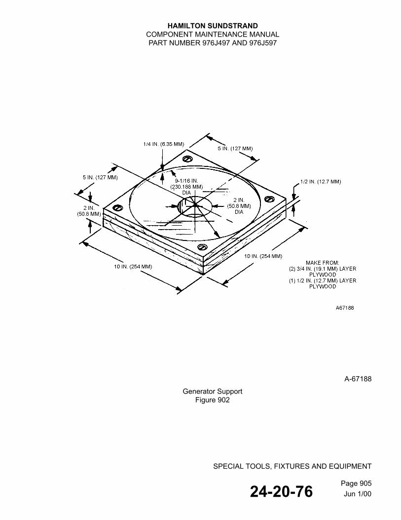
HAMILTON SUNDSTRANDCOMPONENT MAINTENANCE MANUALPART NUMBER 976J497 AND 976J597
SPECIAL TOOLS, FIXTURES AND EQUIPMENT
Page 90524-20-76
A-67188
Generator SupportFigure 902
Jun 1/00

HAMILTON SUNDSTRANDCOMPONENT MAINTENANCE MANUALPART NUMBER 976J497 AND 976J597
SPECIAL TOOLS, FIXTURES AND EQUIPMENT
Page 90624-20-76
A-67189
Cradle FixtureFigure 903
Jun 1/00

HAMILTON SUNDSTRANDCOMPONENT MAINTENANCE MANUALPART NUMBER 976J497 AND 976J597
SPECIAL TOOLS, FIXTURES AND EQUIPMENT
Page 90724-20-76
A-67190
End Bell Removal ToolFigure 904
Jun 1/00

HAMILTON SUNDSTRANDCOMPONENT MAINTENANCE MANUALPART NUMBER 976J497 AND 976J597
SPECIAL TOOLS, FIXTURES AND EQUIPMENT
Page 90824-20-76
A-67191End Bell Assembly Tool
Figure 905
A-67192Alignment Pin
Figure 906
Jun 1/00

HAMILTON SUNDSTRANDCOMPONENT MAINTENANCE MANUALPART NUMBER 976J497 AND 976J597
SPECIAL TOOLS, FIXTURES AND EQUIPMENT
Page 90924-20-76
A-67193
Alignment PinFigure 907
A-67194
Alignment PinFigure 908
Jun 1/00


HAMILTON SUNDSTRANDCOMPONENT MAINTENANCE MANUALPART NUMBER 976J497 AND 976J597
ILLUSTRATED PARTS LIST
Page 100124-20-76
ILLUSTRATED PARTS LIST
1. Introduction
A. The Illustrated Parts List (IPL) provides a breakdown of the equipment covered by this manual. All parts are listed in order of disassembly, showing relationships to higher and lower assemblies, and are identified by corresponding index numbers on board-layout and exploded view illustrations.
B. The part numbers identified in this Illustrated Parts List have been shown to comply with the applicable Federal Aviation Regulations and, when purchased from Hamilton Sundstrand, are FAA-approved under a Hamilton Sundstrand FAA Production Certificate (PC), Technical Standard Order (TSO), or Parts Manufacture Approval (PMA) for use in the component listed.
C. This IPC (or IPL) does not constitute a grant of direct-ship authority, or otherwise confer FAA-approval under FAR 21.303 for parts and assemblies purchased directly from a listed vendor. Installation eligibility of all parts and assemblies purchased directly from a listed vendor must be supported by the vendor's Parts Manufacture Approval (PMA).
D. All items are assigned an item number. Items listed but not illustrated are identified by a dash (-) preceding the item number.
E. For identification of detail parts and assemblies, the NOMENCLATURE column employs the indenture system. Each assembly is listed with its detailed parts list in the next indenture below and to the right. Conversely, the next higher assembly of any detail part may be determined by its location in the indenture above and to the left.
F. Attaching parts immediately follow the part or assembly which they attach and have the same indenture. They are preceded by the words ATTACHING PARTS and are followed by three asterisks (* * *).
G. Effectivity codes (A, B, C...) are assigned and listed in the EFF CODE column, when two or more similar assemblies are broken down in the same IPL figure. These codes show that a part of subassembly is used only on the assembly(ies) with the same effectivity code(s). A part or subassembly with no effectivity code is used on all of the assemblies listed in that figure.
Although the same effectivity codes may be used in more than one IPL figure, there is no relation between the codes of one figure and the codes of any other figure.
To determine end-item effectivity (on which end item a part, subassembly, or assembly is used when multiple end items are listed), find the effectivity code(s) of the item in question. This lead to the assembly(ies) on which the item is used, to the next higher assembly (NHA), and subsequently to the end-item figure and the end item(s).
Feb 26/07

HAMILTON SUNDSTRANDCOMPONENT MAINTENANCE MANUALPART NUMBER 976J497 AND 976J597
ILLUSTRATED PARTS LIST
Page 100224-20-76
H. Unless otherwise indicated by a vendor code number in parentheses following the part name in the parts list, all parts are either commercial standard, military standard, or Hamilton Sundstrand parts.
2. Definitions
The following is a list of terms, their abbreviations (if applicable), and interpretations of how they are used in the IPL of this manual.
If the usage of any of the following terms is the result of a service bulletin, it is noted in the NOMENCLATURE column preceding the term statement. Example: (PRE SB 4)(SUPSD BY XX) or (POST SB 4) (SUPSDS XX).
A. ALTERNATE (ALT). Indicates a part, subassembly, or assembly that fully meets required functional and structural specifications but differs in overall dimensions, connections, installation, or mounting provision, and requires modification to install in a specific application. An alternate item is listed in the FIG-ITEM column as a variant and identified in the NOMENCLATURE column as “(ALT TO XX).”
B. OPTIONAL (OPT). Indicates a choice of interchangeable parts, subassemblies, assemblies, or units that meet or exceed required functional and structural specifications for a given application. Overall dimensions and connections may vary, provided that installation or mounting does not require rework or modification.
An option item is listed in the FIG-ITEM column as a variant and identified in the NOMENCLATURE column as “(OPT TO XX)” or “(VXXXXX) OPTIONAL.”
C. REPLACES/REPLACED (REPLS/REPLD). A part, subassembly, assembly, or unit is replaced when a new part is considered to have superior qualities. Old parts may be used until stock is depleted. A replaced item is listed in the FIG-ITEM column as a variant and identified in the NOMENCLATURE column as “(REPLD BY XX).” The replacing item is listed in the FIG-ITEM column as a variant and identified in the NOMENCLATURE column as “(REPLS XX).”
D. SUPERSEDES/SUPERSEDED (SUPSDS/SUPSD). A part, subassembly, assembly, or unit is superseded when it is not of an alternate or optional nature with the new one. It is due to a design change and is no longer required at the specific application. Old item stock may not be used for replacement. A superseded item is listed in the FIG-ITEM column as a variant and identified in the NOMENCLATURE column as “(SUPSD BY XX).” The superseding item is listed in the FIG-ITEM column as a variant and identified in the NOMENCLATURE column as “(SUPSDS XX).”
E. DELETED. A deleted part, subassembly, assembly, or unit is one which has been removed from a specific application, and no replacement is required. The Figure-Item number and part number of a deleted part are retained in their respective columns. NOMENCLATURE and UNIT/ASSY column information is removed and the word “DELETED” is added to the NOMENCLATURE column.
Feb 26/07

HAMILTON SUNDSTRANDCOMPONENT MAINTENANCE MANUALPART NUMBER 976J497 AND 976J597
ILLUSTRATED PARTS LIST
Page 100324-20-76
CAUTION: ELECTROSTATIC DISCHARGE SENSITIVE (ESDS) ITEMS ARE SUBJECT TO DAMAGE BY EXCESSIVE LEVELS OF VOLTAGE. REFER TO DOD-HDBK-263 FOR PROPER HANDLING PROCEDURES.
F. ELECTROSTATIC DISCHARGE SENSITIVE (ESDS) DEVICES. Electronic parts, assemblies, and equipment that are susceptible to damage from electrostatic discharge. Electrostatic discharge sensitive devices are identified in the NOMENCLATURE column as “(ESDS)”. Refer to REPAIR for information on ESDS.
G. IDENT AS. When a part number is either too long (exceeds fifteen characters) or is not compliant with ATA specifications (contains a slash or other symbols that are not recognized); such as M83248/1-905, the part number would be modified to M83248-1-905 in the part number column and the following would appear in the nomenclature column “IDENT. AS M83248/1-905”.
3. Equipment Designator Index
A. This index contains the reference designators for components shown in the schematic diagrams. The designators are arranged in alphanumerical order and the IPL Figure- Item number(s) are provided.
4. Numerical Index
A. The numerical index is a complete alphanumeric list of all part numbers in the IPL. The Figure-Item number and quantity used at each location are included.
5. Manufacturers' Code, Name, and Address
A. The following list contains the codes, names, and addresses of manufacturers as listed in the Defense Logistics Agency Cataloging Handbook H4/H8, Commercial and Government Entity (CAGE) (formerly FSCM). The CAGE code is a vendor (V) code listed in parentheses in the NOMENCLATURE column of the parts list.
00779 AMP Inc.2800 Fulling Mill RoadP.O. Box 3608Harrisburg, PA 17105-3608
78189 Illinois Tool Works, Inc.Shakeproof DivisionSt. Charles RoadElgin, IL 60120
04866 N-D Industries, Inc.1893 Barrett Rd.Troy, MI 48084
79568 Whittet-Higgins Co.33 Higginson Ave.P.O. Box 8Falls, RI 02863
16941 Long-Lok Fasteners Corp.10630 Chester Rd.Cincinnati, OH 45215-1206
80205 National Aerospace StandardsCommittee
Aerospace Industries Association1250 Eye St. NWWashington, DC 20005
Feb 26/07

HAMILTON SUNDSTRANDCOMPONENT MAINTENANCE MANUALPART NUMBER 976J497 AND 976J597
ILLUSTRATED PARTS LIST
Page 100424-20-76
42838 National Rivet & Mfg Co.1-21 East Jefferson St.Waupun, WI 53963-2038
81349 Military StandardsPromulgated by MilitaryDepartments/Agenciesunder authority of Defense
Standardization Manual 41203-M
45681 Parker-Hannifin Corp.17325 Euclid Ave.Cleveland, OH 44112-1209
83186 Victory Engineering Corp.Victory Rd.Springfield, NJ 07081-1314
50157 Therm-O-Disk Inc.Subsidiary of Emerson Electric Co.1981 Port City Blvd.P.O. Box 787Muskegon, MI 49443
21335 Torrington Co. Fafnir Bearings Div.59 Field St.Torrington, CT 06790-1008
70472 Barnes Group Inc.123 Main St.Bristol, CT 06010-6307
86579 Precision Rubber Products Corp.Dayton, OH 45401
73682 Garrett George K. Co.Div. MSL Industries Inc.Philadelphia, PA 19092
88044 Aeronautical Standards GroupDept. of Navy and Air Force
91265 Goshen Rubber Co., Inc.1525 S. 10th St.P.O. Box 517Goshen, IN 46526-4505
96906 Military StandardsPromulgated by Military
Departments/Agenciesunder authority of Defense
Standardization Manual 41203-M
99167 Hamilton Sundstrand4747 Harrison AvenueP.O. Box 7002Rockford, IL 61125-7002
Feb 26/07

HAMILTON SUNDSTRANDCOMPONENT MAINTENANCE MANUALPART NUMBER 976J497 AND 976J597
NUMERICAL INDEX
Page 100524-20-76
NUMERICAL INDEX
PART NUMBERAIRLINE
PART NO. FIG. ITEMTTLREQ
A116COMPSR277-20 1A 30A 1A116COMP-SR277-70 1 3 1
1A 30AN500A8-7 1 24G 6
1A 240G 6AN502-10-10 1 28 6
1 49 4 1A 280 61A 490 4
AN502-10-12 1 9 6 1A 90 6
AN502-10-14 1 9A 6 1A 90A 6
AN502-10-6 1 54 8 1A 540 8
AN503-8-10 1 11A 6 1 21A 2 1 25A 12
1A 110A 61A 210A 21A 250A 12
AN503-8-12 1 21 2 3 9 5
1A 210 23A 90 5
AN960-10 1 50 4 1 53 8
1A 500 41A 530 8
AN960-10L 1 18 4 1A 180 4
AN960-416L 4 7 6 4A 70 6
AN960-616 1 46 6 1A 460 6
AN960-8 1 15 2 1 22 2 1 24K 6 3 10 5
1A 150 21A 220 21A 240K 63A 100 5
GRC513-215COMP 3A 70A 1GRC513-215-COMP-PV1504 3 7 1
3A 70 1
Feb 26/07

HAMILTON SUNDSTRANDCOMPONENT MAINTENANCE MANUALPART NUMBER 976J497 AND 976J597
NUMERICAL INDEX
Page 100624-20-76
PART NUMBERAIRLINE
PART NO. FIG. ITEMTTLREQ
L591-19357 1 7 1 3 6 1
1A 70 13A 60 1
LP500-8-6 1 14A 2 1A 140A 2
M83248-1-116 1 3C 1 1A 30D 1
MS122159 1 65 12 1A 650 12
MS124655 1 64 8 1A 640 8
MS16625-1093 1 2 1 1A 20 1
MS16625-1131 3 5 1 3A 50 1
MS16625-1168 4 1 1 4A 10 1
MS16628-4118 1 38 1 1A 380 1
MS21042-L4 4 6 6 4A 60 6
MS21042L4 4A 60A 6MS21208F1-20 1 32 6
1A 320 6MS21209C0-815 1 31 4
1A 310 4MS21209F1-15 1 11B 6
1 33 6 1A 110B 61A 330 6
MS24677-16 1 11 6 1 25 12
1A 110 61A 250 12
MS24678-9 1 54A 8 1A 540A 8
MS24678-15 1A 110B 6MS25036-108 1 29A 3
2 11 3 1A 290A 32A 110 3
MS25036-56 3 13M 3 3A 130M 3
MS35338-40 1 69 4 1A 690 4
MS35338-43 1 17 4 1A 170 4
Feb 26/07

HAMILTON SUNDSTRANDCOMPONENT MAINTENANCE MANUALPART NUMBER 976J497 AND 976J597
NUMERICAL INDEX
Page 100724-20-76
PART NUMBERAIRLINE
PART NO. FIG. ITEMTTLREQ
MS35338-46 1 45 6 1A 450 6
MS35458-30 1 6 1 1A 60 1
MS35650-305T 1 19 4 1A 190 4
NAS679A3W 1 16 4 1A 160 4
NAS679A6 1 44A 6 1A 440A 6
NAS679A6W 1 44 1A 440
NK500-8-6CC 1 14 2 1A 140 2
PMW206PPC4FA-52695S8 1 36 1A 360
TC1-6-ST 4 13 6 4A 130 6
TC1-6ST 4A 130A 6W-06 1 39 1
1A 390 1109P938 1 67A 1
1A 670A 1109P938-1 1A 670B 1116COMP17107 1 3A 1
1A 30B 111X1 2 1B 1
2A 10B 114C4796-7 SEE W-0615C7989-2 SEE MS24677-1615C7989-38 SEE MS24678-915C7989-45 SEE AN503-8-1015C8030-7 1 40 1
1A 400 115C8095-55 SEE MS35458-3018B1766-18 SEE MS16625-109318B1766-23 SEE MS16625-113118B1766-24 SEE MS16625-116819C8355-33 SEE TC1-6-ST2-116COMPV747 1 3B 1
1A 30C 12-215-V747 3 7B 1
3A 70C 12-215V747 3A 70D 1215COMP19357 3 7A 1
3A 70B 128B8800-3 1 68 4
1A 680 4
Feb 26/07

HAMILTON SUNDSTRANDCOMPONENT MAINTENANCE MANUALPART NUMBER 976J497 AND 976J597
NUMERICAL INDEX
Page 100824-20-76
PART NUMBERAIRLINE
PART NO. FIG. ITEMTTLREQ
28B8802-33 SEE AN503-8-1228B8802-34 SEE AN503-8-1028B8802-6 1 35 2
1A 350 228B8802-9 2 2 1
2A 20 128B8803-45 SEE MS24677-1628B8803-90 SEE AN502-10-1228B8803-91 SEE AN502-10-1428B8803-93 SEE AN502-10-1028B8803-99 SEE AN502-10-628B9560-3 SEE NK500-8-6CC
SEE LP500-8-62W756 2 1 1
2A 10 12WD1007501 2 1A 1
2A 10A 13-243650-2-323 2 3 1
2A 30 131398 2 9 2
2A 90 23530-05-03 4 14 6
4A 140 65908349 4 4A 3
4A 40A 35908350 4 5A 3
4A 50A 35911588 4 4B 3
4A 40B 35911589 4 5B 3
4A 50B 362276 1 67 1
1A 670 1769450 3 1B 1
3A 10B 18C7714-34 1 36A 2
1A 360A 2908C828-1 1 13 1
1A 130 1908C832-1 1 20 1
1A 200 1908D049-1 1 43 1
1A 430 1908D049-2 1A 430A 1910C331-10 SEE AN960-10910C331-11 SEE AN960-416L910C331-16 SEE AN960-616910C331-8 SEE AN960-8910C331-9 SEE AN960-10L
Feb 26/07

HAMILTON SUNDSTRANDCOMPONENT MAINTENANCE MANUALPART NUMBER 976J497 AND 976J597
NUMERICAL INDEX
Page 100924-20-76
PART NUMBERAIRLINE
PART NO. FIG. ITEMTTLREQ
910C605-1 1 4 1 1A 40 1
910C886-1 SEE A116COMP-SR277-SEE 116COMP17107SEE M83248-1-116SEE 2-116COMPV747
911C207-15 SEE MS35338-46911C207-3 SEE MS35338-40911C207-9 SEE MS35338-43915F262-1 1 27 1
1A 270 12 RF
2A 1 RF915F306-1 1 42 1
1A 420 13 RF
3A 1 RF915F306-2 1 42B 1
1A 420B 13 RF
3A 1B RF915F469-1 1 55 1
1A 550 1915F469-2 1 55A 1
1A 550A 1915F508-1 1 42A 1
1A 420A 13 RF
3A 1A RF915F511-1 1 27A 1
1A 270A 12 RF
2A 1A RF915F512-2 1 55B 1
1A 550B 1916B631-1 SEE MS21209F1-15916B631-2 SEE MS21209C0-815916B631-3 3 3M 1
3A 30M 1916B821-1 2 4 1
2A 40 1916B822-1 2 7 2
2A 70 2916B825-2 SEE 2W756
SEE 2WD1007501SEE 11X1
917B106-1 SEE 31398917B119-11 SEE MS122159917B119-3 SEE MS124655917B119-6 SEE MS21208F1-20917B453-5 SEE MS16628-4118
Feb 26/07

HAMILTON SUNDSTRANDCOMPONENT MAINTENANCE MANUALPART NUMBER 976J497 AND 976J597
NUMERICAL INDEX
Page 101024-20-76
PART NUMBERAIRLINE
PART NO. FIG. ITEMTTLREQ
917B579-1 1 23 4 1A 230 4
917B596-1 2 6 2 2A 60 2
917B597-1 SEE 3-243650-2-323917B599-1 1 24 1
1A 240 1917B621-1 2 10 3
2 10A 2 2A 100 32A 100A 2
918B105-2 SEE NAS679A3W918B105-4 SEE NAS679A6W919B113-1 1 1 1
1A 10 1920B836-1 1 37 4
1A 370 49206WX7C0XG-29 1 36B 2
1A 360B 2922B314-1 1 5 1
1A 50 1927A402-19 SEE MS25036-108927A402-25 SEE MS25036-56929A939-1 1 26 6
1 26A 12 1A 260 61A 260A 12
931A052-1 4 15E 2 4A 150E 2
931A052-2 4 15F 2 4A 150F 2
936C235-1 1 10 1 1A 100 1
938D679-11 4 4 3 4A 40 3
938D679-12 4 5 3 4A 50 3
939D982-1 3 2 8 3A 20 8
940D366-1 3 1 1 3A 10 1
941D586-2 3 13 1 3A 130 1
942D262-2 3 13A 1 3A 130A 1
943D450-1 1 30A 1 1A 300A 1
944B718-1 1 8 1 1A 80 1
944B791-1 1 47 6 1A 470 6
Feb 26/07

HAMILTON SUNDSTRANDCOMPONENT MAINTENANCE MANUALPART NUMBER 976J497 AND 976J597
NUMERICAL INDEX
Page 101124-20-76
PART NUMBERAIRLINE
PART NO. FIG. ITEMTTLREQ
944B851-1 2 8 1 2A 80 1
944B852-1 2 5 2 2A 50 2
945B161-1 1 7A 1 1A 70A 13 6A 1
3A 60A 1SEE L591-19357
945B477-1 1 30F 1 1A 300F 1
945B527-1 3 3 1 3A 30 1
945B527-2 3 3A 13A 30A 1
945B550-1 3 4 1 3A 40 1
945B985-1 1 51 6 1A 510 6
946F177-1 3 8 1 3A 80 14 RF
4A 1 RF946F177-3 3 8A 1
3A 80A 14 RF
4A 1A RF947B438-1 3 13R 16
3A 130R 16947B449-1 3 12 5
3A 120 5947B450-1 3 11 5
3A 110 5947B451-1 4 3M 2
4A 30M 2947B473-1 4 8 3
4A 80 3947B495-1 1 12 6
1A 120 6947B529-1 1 61 2
1A 610 2947B529-6 1 63 1
1A 630 1947B529-7 1 62 3
1A 620 3947B872-2 4 14A
4A 140ASEE 947B872-2SEE 3530-05-03
Feb 26/07

HAMILTON SUNDSTRANDCOMPONENT MAINTENANCE MANUALPART NUMBER 976J497 AND 976J597
NUMERICAL INDEX
Page 101224-20-76
PART NUMBERAIRLINE
PART NO. FIG. ITEMTTLREQ
948B029-1 1 12A 6 1 29 6 1 53A 8
1A 120A 61A 290 61A 530A 8
948B031-1 4 12 2 4A 120 AR
948B032-1 4 9 2 4A 90 AR
948B034-1 4 10 1 4A 100 1
948B212-1 1 57 1 1A 570 1
948B213-1 1 60 1 1A 600 1
948B214-1 1 58 2 1A 580 2
948B215-1 1 59 1 1A 590 1
948B216-1 1 56 1 1A 560 1
949B105-3 3 14 AR 3A 140 AR
949B105-5 3 15 AR 3A 150 AR
949B105-6 3 16 AR 3A 160 AR
949B352-1 4 2 1 4A 20 1
949B362-1 4 11 1 4A 110 AR
949B363-1 4 10B 14A 100B AR
949F308-1 3 1A 13A 10A 1
949F363-1 4 10A 4A 100A
955C170-86 1 66 3 1A 660 3
955C551-14 SEE MS35650-305T959C442-2 SEE GRC513-215-COMP-
SEE 215COMP19357SEE 2-215-V747
959C711-5 SEE MS21042-L4961C451-1 4 15 1
4A 150 1961C730-1 1 52 1
1A 520 1
Feb 26/07

HAMILTON SUNDSTRANDCOMPONENT MAINTENANCE MANUALPART NUMBER 976J497 AND 976J597
NUMERICAL INDEX
Page 101324-20-76
PART NUMBERAIRLINE
PART NO. FIG. ITEMTTLREQ
962C235-3 1 10A 1 1A 100A 1
962C261-1 1 41 2 1A 410 2
962C265-1 4 3 1 4A 30 1
962C279-1 1 24D 1 1A 240D 1
963C047-1 1 30 1 1A 300 1
963C054-1 1 48 1 1A 480 1
963C055-1 1 34 1 1A 340 1
964C157-2 4 16 1 4A 160 1
964C592-1 4 18 1 4A 180 1
966C576-1 1 52A 1 1A 520A 1
976J497-1 1 RF 1A 1 RF
976J597-1 1 RF 1A 1A RF
Feb 26/07

HAMILTON SUNDSTRANDCOMPONENT MAINTENANCE MANUALPART NUMBER 976J497 AND 976J597
ILLUSTRATED PARTS LIST
Page 101424-20-76
A-68064AC Generator
Figure 1 (Sheet 1 of 2)
Feb 26/07

HAMILTON SUNDSTRANDCOMPONENT MAINTENANCE MANUALPART NUMBER 976J497 AND 976J597
ILLUSTRATED PARTS LIST
Page 101524-20-76
A-67987
AC GeneratorFigure 1 (Sheet 2 of 2)
Feb 26/07

HAMILTON SUNDSTRANDCOMPONENT MAINTENANCE MANUALPART NUMBER 976J497 AND 976J597
ILLUSTRATED PARTS LIST
Page 101624-20-76
FIG.ITEM
PARTNUMBER 1 2 3 4 5 6 7 NOMENCLATURE
EFFCODE
UNITSPER
ASSY1 976J497-1 GENERATOR, AC
(MOVED TO ITEM 1 IPL FIGURE 1A)A RF
976J597-1 GENERATOR, AC (MOVED TO ITEM 1A IPL FIGURE 1A)
B RF
1 919B113-1 • COVER, SPINDLE (MOVED TO ITEM 10 IPL FIGURE 1A)
1
ATTACHING PARTS 2 MS16625-1093 • RING, RETAINING
(MOVED TO ITEM 20 IPL FIGURE 1A) 1
-----*----- 3 A116COMP-SR277-70 • PACKING, PREFORMED
(MOVED TO ITEM 30 IPL FIGURE 1A) 1
-3A 116COMP17107 • PACKING, PREFORMED (MOVED TO ITEM 30B IPL FIGURE 1A)
1
-3B 2-116COMPV747 • PACKING, PREFORMED (MOVED TO ITEM 30C IPL FIGURE 1A)
1
-3C M83248-1-116 • PACKING, PREFORMED (MOVED TO ITEM 30D IPL FIGURE 1A)
1
4 910C605-1 • ADAPTER, SPLINE (MOVED TO ITEM 40 IPL FIGURE 1A)
1
ATTACHING PARTS 5 922B314-1 • WASHER, SHOULDERED
(MOVED TO ITEM 50 IPL FIGURE 1A) 1
6 MS35458-30 • SCREW, MACHINE (MOVED TO ITEM 60 IPL FIGURE 1A)
1
-----*----- 7 L591-19357 • PACKING, PREFORMED
(MOVED TO ITEM 70 IPL FIGURE 1A) 1
-7A 945B161-1 • PACKING, PREFORMED (MOVED TO ITEM 70A IPL FIGURE 1A)
1
8 944B718-1 • RING, BACKING (MOVED TO ITEM 80 IPL FIGURE 1A)
1
ATTACHING PARTS 9 AN502-10-12 • SCREW
(MOVED TO ITEM 90 IPL FIGURE 1A) 6
-----*----- 9A AN502-10-14 • SCREW
(MOVED TO ITEM 90A IPL FIGURE 1A) 6
Feb 26/07
- ITEM NOT ILLUSTRATED

HAMILTON SUNDSTRANDCOMPONENT MAINTENANCE MANUALPART NUMBER 976J497 AND 976J597
ILLUSTRATED PARTS LIST
Page 101724-20-76
FIG.ITEM
PARTNUMBER 1 2 3 4 5 6 7 NOMENCLATURE
EFFCODE
UNITSPER
ASSY1 10 936C235-1 • COVER, BEARING
(MOVED TO ITEM 100 IPL FIGURE 1A) 1
-10A 962C235-3 • COVER, BEARING (MOVED TO ITEM 100A IPL FIGURE 1A)
1
ATTACHING PARTS 11 MS24677-16 • SCREW
(MOVED TO ITEM 110 IPL FIGURE 1A) 6
-11A AN503-8-10 • SCREW(MOVED TO ITEM 110A IPL FIGURE 1A)
6
-11B MS24678-15 • SCREW(MOVED TO ITEM 110B IPL FIGURE 1A)
6
12 947B495-1 • WASHER, FLAT(MOVED TO ITEM 120 IPL FIGURE 1A)
6
-12A 948B029-1 • WASHER, FLAT(MOVED TO ITEM 120A IPL FIGURE 1A)
6
-----*----- 13 908C828-1 • COVER, TERMINAL BOARD
(MOVED TO ITEM 130 IPL FIGURE 1A) 1
ATTACHING PARTS 14 NK500-8-6CC • SCREW, SELF LOCKING, MACH., 8-32
UNC-2A X 0.375 CD PL (MOVED TO ITEM 140 IPL FIGURE 1A)
2
-14A LP500-8-6 • SCREW, SELF LOCKING, MACH., 8-32 UNC-2A X 0.375 CD PL (MOVED TO ITEM 140A IPL FIGURE 1A)
2
15 AN960-8 • WASHER, FLAT(MOVED TO ITEM 150 IPL FIGURE 1A)
2
-----*----- 16 NAS679A3W • NUT, SELF LOCKING
(MOVED TO ITEM 160 IPL FIGURE 1A) 4
17 MS35338-43 • WASHER, LOCK(MOVED TO ITEM 170 IPL FIGURE 1A)
4
18 AN960-10L • WASHER, FLAT (MOVED TO ITEM 180 IPL FIGURE 1A)
4
19 MS35650-305T • NUT, PLAIN HEX(MOVED TO ITEM 190 IPL FIGURE 1A)
4
Feb 26/07
- ITEM NOT ILLUSTRATED

HAMILTON SUNDSTRANDCOMPONENT MAINTENANCE MANUALPART NUMBER 976J497 AND 976J597
ILLUSTRATED PARTS LIST
Page 101824-20-76
FIG.ITEM
PARTNUMBER 1 2 3 4 5 6 7 NOMENCLATURE
EFFCODE
UNITSPER
ASSY1 20 908C832-1 • TERMINAL BOARD
(MOVED TO ITEM 200 IPL FIGURE 1A) 1
ATTACHING PARTS 21 AN503-8-12 • SCREW, MACHINE
(MOVED TO ITEM 210 IPL FIGURE 1A)A 2
21A AN503-8-10 • SCREW, MACHINE (MOVED TO ITEM 210A IPL FIGURE 1A)
B 2
22 AN960-8 • WASHER, FLAT (MOVED TO ITEM 220 IPL FIGURE 1A)
2
-----*----- 23 917B579-1 • TERMINAL, STUD
(MOVED TO ITEM 230 IPL FIGURE 1A) 4
24 917B599-1 • GROMMET (MOVED TO ITEM 240 IPL FIGURE 1A)
1
-24D 962C279-1 • FLANGE (NP) (MOVED TO ITEM 240D IPL FIGURE 1A)
A 1
ATTACHING PARTS -24G AN500A8-7 • SCREW, MACH, FIL H
(MOVED TO ITEM 240G IPL FIGURE 1A)A 6
-24K AN960-8 • WASHER (MOVED TO ITEM 240K IPL FIGURE 1A)
A 6
-----*-----
25 MS24677-16 • SCREW, MACH(MOVED TO ITEM 250 IPL FIGURE 1A)
12
-25A AN503-8-10 • SCREW, MACHINE(MOVED TO ITEM 250A IPL FIGURE 1A)
12
26 929A939-1 • WASHER (MOVED TO ITEM 260 IPL FIGURE 1A)
6
26A 929A939-1 • WASHER, FLAT (MOVED TO ITEM 260A IPL FIGURE 1A)
12
27 915F262-1 • STATOR, EXCITER (MOVED TO ITEM 270 IPL FIGURE 1A)
A 1
Feb 26/07
-ITEM NOT ILLUSTRATED

HAMILTON SUNDSTRANDCOMPONENT MAINTENANCE MANUALPART NUMBER 976J497 AND 976J597
ILLUSTRATED PARTS LIST
Page 101924-20-76
FIG.ITEM
PARTNUMBER 1 2 3 4 5 6 7 NOMENCLATURE
EFFCODE
UNITSPER
ASSY1 -27A 915F511-1 • STATOR, EXCITER (CUBEX)
(MOVED TO ITEM 270A IPL FIGURE 1A)B 1
ATTACHING PARTS
28 AN502-10-10 • SCREW, MACHINE(MOVED TO ITEM 280 IPL FIGURE 1A)
6
29 948B029-1 • WASHER, FLAT (MOVED TO ITEM 290 IPL FIGURE 1A)
6
-----*----- 29A MS25036-108 • TERMINAL LUG
(MOVED TO ITEM 290A IPL FIGURE 1A) 3
30 963C047-1 • END BELL, ELEC. ROTATING (MOVED TO ITEM 300 IPL FIGURE 1A)
A 1
-30A 943D450-1 • END BELL, ELEC. ROTATING (MOVED TO ITEM 300A IPL FIGURE 1A)
B 1
30F 945B477-1 • • INSERT, BEARING (MOVED TO ITEM 300F IPL FIGURE 1A)
1
31 MS21209C0-815 • • INSERT, SCREW THREAD(MOVED TO ITEM 310 IPL FIGURE 1A)
4
32 MS21208F1-20 • • INSERT, SCREW THREAD (MOVED TO ITEM 320 IPL FIGURE 1A)
6
33 MS21209F1-15 • • INSERT, SCREW THREAD (MOVED TO ITEM 330 IPL FIGURE 1A)
6
34 963C055-1 • • RETAINER (MOVED TO ITEM 340 IPL FIGURE 1A)
1
ATTACHING PARTS 35 28B8802-6 • • SCREW, FIL H 8-32 UNC-2A X 0.44 CD PL
(MOVED TO ITEM 350 IPL FIGURE 1A) 2
-----*----- 36 PMW206PPC4FA-
52695S8 DELETED (BEARING, BALL)
(MOVED TO ITEM 360 IPL FIGURE 1A)
-36A 8C7714-34 • BEARING, BALL (MOVED TO ITEM 360A IPL FIGURE 1A)
2
-36B 9206WX7C0XG-29 • BEARING, BALL(MOVED TO ITEM 360B IPL FIGURE 1A)
2
Feb 26/07
- ITEM NOT ILLUSTRATED

HAMILTON SUNDSTRANDCOMPONENT MAINTENANCE MANUALPART NUMBER 976J497 AND 976J597
ILLUSTRATED PARTS LIST
Page 102024-20-76
FIG.ITEM
PARTNUMBER 1 2 3 4 5 6 7 NOMENCLATURE
EFFCODE
UNITSPER
ASSY1 37 920B836-1 • SHIELD, BEARING
(MOVED TO ITEM 370 IPL FIGURE 1A) 4
ATTACHING PARTS 38 MS16628-4118 • RING, RETAINING
(MOVED TO ITEM 380 IPL FIGURE 1A) 1
39 W-06 • WASHER, KEY (MOVED TO ITEM 390 IPL FIGURE 1A)
1
40 15C8030-7 • NUT, PLAIN, ROUND (MOVED TO ITEM 400 IPL FIGURE 1A)
1
-----*----- 41 962C261-1 • COVER, BEARING
(MOVED TO ITEM 410 IPL FIGURE 1A) 2
42 915F306-1 • ARMATURE-ROTOR (MOVED TO ITEM 420 IPL FIGURE 1A)
A 1
-42A 915F508-1 • ARMATURE-ROTOR (CUBEX) (NP) (MOVED TO ITEM 420A IPL FIGURE 1A)
B 1
-42B 915F306-2 • ARMATURE-ROTOR (MOVED TO ITEM 420B IPL FIGURE 1A)
A 1
43 908D049-1 • COVER, TERMINAL BOARD (MOVED TO ITEM 430 IPL FIGURE 1A)
1
44 NAS679A6W • DELETED (NUT)(MOVED TO ITEM 440 IPL FIGURE 1A)
-44A NAS679A6 • NUT, SELF LOCK (MOVED TO ITEM 440A IPL FIGURE 1A)
6
45 MS35338-46 • WASHER, LOCK(MOVED TO ITEM 450 IPL FIGURE 1A)
6
46 AN960-616 • WASHER, FLAT (MOVED TO ITEM 460 IPL FIGURE 1A)
6
47 944B791-1 • WASHER, SHOULDERED, SQUARE (MOVED TO ITEM 470 IPL FIGURE 1A)
6
48 963C054-1 • TERMINAL BOARD (MOVED TO ITEM 480 IPL FIGURE 1A)
1
ATTACHING PARTS 49 AN502-10-10 • SCREW, MACHINE
(MOVED TO ITEM 490 IPL FIGURE 1A) 4
50 AN960-10 • WASHER, FLAT(MOVED TO ITEM 500 IPL FIGURE 1A)
4
-----*-----
Feb 26/07
- ITEM NOT ILLUSTRATED

HAMILTON SUNDSTRANDCOMPONENT MAINTENANCE MANUALPART NUMBER 976J497 AND 976J597
ILLUSTRATED PARTS LIST
Page 102124-20-76
FIG.ITEM
PARTNUMBER 1 2 3 4 5 6 7 NOMENCLATURE
EFFCODE
UNITSPER
ASSY1 51 945B985-1 • • STUD, MACHINE, HEX HD
(MOVED TO ITEM 510 IPL FIGURE 1A) 6
52 961C730-1 • END BELL, ELEC. ROTATING (MOVED TO ITEM 520 IPL FIGURE 1A)
1
52A 966C576-1 • END BELL, ELEC. ROTATING (MOVED TO ITEM 520A IPL FIGURE 1A)
1
ATTACHING PARTS 53 AN960-10 • WASHER
(MOVED TO ITEM 530 IPL FIGURE 1A) 8
-53A 948B029-1 • WASHER, FLAT (MOVED TO ITEM 530A IPL FIGURE 1A)
8
54 AN502-10-6 • SCREW (MOVED TO ITEM 540 IPL FIGURE 1A)
8
-54A MS24678-9 • SCREW(MOVED TO ITEM 540A IPL FIGURE 1A)
8
-----*----- 55 915F469-1 • STATOR, GENERATOR
(MOVED TO ITEM 550 IPL FIGURE 1A)A 1
-55A 915F469-2 • STATOR, GENERATOR (MOVED TO ITEM 550A IPL FIGURE 1A)
A 1
-55B 915F512-2 • STATOR, GENERATOR (CUBEX) (NP)(MOVED TO ITEM 550B IPL FIGURE 1A)
B 1
56 948B216-1 • • TERMINAL, ELECTRICAL (MOVED TO ITEM 560 IPL FIGURE 1A)
1
57 948B212-1 • • TERMINAL, ELECTRICAL (MOVED TO ITEM 570 IPL FIGURE 1A)
1
58 948B214-1 • • TERMINAL, ELECTRICAL (MOVED TO ITEM 580 IPL FIGURE 1A)
2
59 948B215-1 • • TERMINAL, ELECTRICAL (MOVED TO ITEM 590 IPL FIGURE 1A)
1
60 948B213-1 • • TERMINAL, ELECTRICAL (MOVED TO ITEM 600 IPL FIGURE 1A)
1
61 947B529-1 • • INSULATION, SLEEVING (MOVED TO ITEM 610 IPL FIGURE 1A)
2
62 947B529-7 • • INSULATION, SLEEVING (MOVED TO ITEM 620 IPL FIGURE 1A)
3
63 947B529-6 • • INSULATION, SLEEVING (MOVED TO ITEM 630 IPL FIGURE 1A)
1
64 MS124655 • • INSERT (MOVED TO ITEM 640 IPL FIGURE 1A)
8
65 MS122159 • • INSERT (MOVED TO ITEM 650 IPL FIGURE 1A)
12
Feb 26/07
- ITEM NOT ILLUSTRATED

HAMILTON SUNDSTRANDCOMPONENT MAINTENANCE MANUALPART NUMBER 976J497 AND 976J597
ILLUSTRATED PARTS LIST
Page 102224-20-76
FIG.ITEM
PARTNUMBER 1 2 3 4 5 6 7 NOMENCLATURE
EFFCODE
UNITSPER
ASSY1 66 955C170-86 • • SCREW
(MOVED TO ITEM 660 IPL FIGURE 1A) 3
67 62276 • PLATE, IDENTIFICATION (NP) (MOVED TO ITEM 670 IPL FIGURE 1A)
1
-67A 109P938 • PLATE, IDENTIFICATION(MOVED TO ITEM 670A IPL FIGURE 1A)
1
-67B 109P938-1 • PLATE, IDENTIFICATION (MOVED TO ITEM 670B IPL FIGURE 1A)
1
ATTACHING PARTS 68 28B8800-3 • SCREW, MACHINE, FIL HD STL,
CD PL 4-40 X 1/4 INCH LG (MOVED TO ITEM 680 IPL FIGURE 1A)
4
69 MS35338-40 • WASHER, LOCK (MOVED TO ITEM 690 IPL FIGURE 1A)
4
-----*-----
Feb 26/07

HAMILTON SUNDSTRANDCOMPONENT MAINTENANCE MANUALPART NUMBER 976J497 AND 976J597
ILLUSTRATED PARTS LIST
Page 102324-20-76
THIS PAGE INTENTIONALLY LEFT BLANK
Feb 26/07

HAMILTON SUNDSTRANDCOMPONENT MAINTENANCE MANUALPART NUMBER 976J497 AND 976J597
ILLUSTRATED PARTS LIST
Page 102424-20-76
HE-242076-68064-A
AC GeneratorFigure 1A (Sheet 1 of 2)
Feb 26/07

HAMILTON SUNDSTRANDCOMPONENT MAINTENANCE MANUALPART NUMBER 976J497 AND 976J597
ILLUSTRATED PARTS LIST
Page 102524-20-76
HE-242076-67987-A
AC GeneratorFigure 1A (Sheet 2 of 2)
Feb 26/07

HAMILTON SUNDSTRANDCOMPONENT MAINTENANCE MANUALPART NUMBER 976J497 AND 976J597
ILLUSTRATED PARTS LIST
Page 102624-20-76
FIG.ITEM
PARTNUMBER 1 2 3 4 5 6 7 NOMENCLATURE
EFFCODE
UNITSPER
ASSY1A -1 976J497-1 GENERATOR, AC A RF -1A 976J597-1 GENERATOR, AC B RF 10 919B113-1 • COVER, SPINDLE 1 ATTACHING PARTS 20 MS16625-1093 • RING, RETAINING
(18B1766-18) 1
-----*----- 30 A116COMP-SR277-70 DELETED (PACKING, PREFORMED) -30A A116COMPSR277-70 • PACKING, PREFORMED
(V95272) (910C886-1)IDENT AS A116COMP-SR277-70
1
-30B 116COMP17107 • PACKING, PREFORMED (V25184) (910C886-1)
1
-30C 2-116COMPV747 • PACKING, PREFORMED (V45681) (910C886-1)
1
-30D M83248-1-116 • PACKING, PREFORMED (910C886-1)
1
40 910C605-1 • ADAPTER, SPLINE 1 ATTACHING PARTS 50 922B314-1 • WASHER, SHOULDERED 1 60 MS35458-30 • SCREW, MACHINE
(15C8095-55) 1
-----*----- 70 L591-19357 • PACKING, PREFORMED
(V86579) (945B161-1) 1
-70A 945B161-1 • PACKING, PREFORMED (V45681)
1
Feb 26/07
- ITEM NOT ILLUSTRATED

HAMILTON SUNDSTRANDCOMPONENT MAINTENANCE MANUALPART NUMBER 976J497 AND 976J597
ILLUSTRATED PARTS LIST
Page 102724-20-76
FIG.ITEM
PARTNUMBER 1 2 3 4 5 6 7 NOMENCLATURE
EFFCODE
UNITSPER
ASSY1A 80 944B718-1 • RING, BACKING
(USED WITH END BELL 961C730-1, ITEM 520. END BELL AND RING REPLD BY 966C576-1, ITEM 520A. USE UP SPARES) (S.B. 78-103)
1
ATTACHING PARTS 90 AN502-10-12 • SCREW (28B8803-90)
(USED WITH ITEMS 520 AND 80. REPLD BY ITEM 520A. SCREWS REPLD BY ITEM 90A.) (S.B. 78-103)
6
-----*----- 90A AN502-10-14 • SCREW (28B8803-91)
(USED WITH ITEM 520A.) (S.B. 78-103)
6
100 936C235-1 • COVER, BEARING (REPLD BY ITEM -100A) (S.B. 79-103)
1
-100A 962C235-3 • COVER, BEARING (REPLS ITEM 100) (S.B. 79-103)
1
ATTACHING PARTS 110 MS24677-16 • SCREW
(28B8803-45) (REPLD BY ITEM 110A)(S.B. 84-103)
6
-110A AN503-8-10 • SCREW (15C7989-45) (REPLS ITEM 110)(REPLD BY ITEM 110B)
6
-110B MS24678-15 • SCREW (15C7989) (REPLS ITEM 110A)
6
120 947B495-1 • WASHER, FLAT (REPLD BY ITEM -120A) (S.B. 84-103)
6
-120A 948B029-1 • WASHER, FLAT (REPLS ITEM 120)
6
-----*-----
Feb 26/07
- ITEM NOT ILLUSTRATED

HAMILTON SUNDSTRANDCOMPONENT MAINTENANCE MANUALPART NUMBER 976J497 AND 976J597
ILLUSTRATED PARTS LIST
Page 102824-20-76
FIG.ITEM
PARTNUMBER 1 2 3 4 5 6 7 NOMENCLATURE
EFFCODE
UNITSPER
ASSY1A 130 908C828-1 • COVER, TERMINAL BOARD 1 ATTACHING PARTS 140 NK500-8-6CC • SCREW, SELF LOCKING, MACH., 8-32
UNC-2A X 0.375 CD PL (V04866) (28B9560-3)
2
-140A LP500-8-6 • SCREW, SELF LOCKING, MACH., 8-32 UNC-2A X 0.375 CD PL (V16941) (28B9560-3)
2
150 AN960-8 • WASHER, FLAT (910C331-8)
2
-----*----- 160 NAS679A3W • NUT, SELF LOCKING
(918B105-2) 4
170 MS35338-43 • WASHER, LOCK (911C207-9)
4
180 AN960-10L • WASHER, FLAT (910C331-9)
4
190 MS35650-305T • NUT, PLAIN HEX (955C551-14)
4
200 908C832-1 • TERMINAL BOARD 1 ATTACHING PARTS 210 AN503-8-12 • SCREW, MACHINE
(28B8802-33) A 2
-210A AN503-8-10 • SCREW, MACHINE (28B8802-34)
B 2
220 AN960-8 • WASHER, FLAT (910C331-8)
2
-----*----- 230 917B579-1 • TERMINAL, STUD 4 240 917B599-1 • GROMMET 1 -240D 962C279-1 • FLANGE (NP) A 1 ATTACHING PARTS -240G AN500A8-7 • SCREW, MACH, FIL H A 6 -240K AN960-8 • WASHER A 6 -----*----- -250 MS24677-16 • SCREW, MACH
(15C7989-2) 12
250A AN503-8-10 • SCREW, MACHINE (28B8802-34)
12
Feb 26/07
- ITEM NOT ILLUSTRATED

HAMILTON SUNDSTRANDCOMPONENT MAINTENANCE MANUALPART NUMBER 976J497 AND 976J597
ILLUSTRATED PARTS LIST
Page 102924-20-76
FIG.ITEM
PARTNUMBER 1 2 3 4 5 6 7 NOMENCLATURE
EFFCODE
UNITSPER
ASSY1A -260 929A939-1 • WASHER 6 260A 929A939-1 • WASHER, FLAT 12 270 915F262-1 • STATOR, EXCITER
(SEE IPL FIGURE 2A FOR DETAILS.) A 1
-270A 915F511-1 • STATOR, EXCITER (CUBEX) (SEE IPL FIGURE 2A FOR DETAILS.)
B 1
ATTACHING PARTS
280 AN502-10-10 • SCREW, MACHINE (28B8803-93) 6 290 948B029-1 • WASHER, FLAT 6 -----*----- 290A MS25036-108 • TERMINAL LUG (927A402-19) 3 300 963C047-1 • END BELL, ELEC. ROTATING A 1 -300A 943D450-1 • END BELL, ELEC. ROTATING B 1 300F 945B477-1 • • INSERT, BEARING 1 310 MS21209C0-815 • • INSERT, SCREW THREAD
(V96906) (916B631-2) 4
320 MS21208F1-20 • • INSERT, SCREW THREAD (V96906) (917B119-6)
6
330 MS21209F1-15 • • INSERT, SCREW THREAD (V96906) (916B631-1)
6
340 963C055-1 • • RETAINER 1
ATTACHING PARTS 350 28B8802-6 • • SCREW, FIL H 8-32 UNC-2A X 0.44 CD PL 2 -----*----- 360 PMW206PPC4FA-
52695S8 DELETED (BEARING, BALL)
-360A 8C7714-34 • BEARING, BALL 2 -360B 9206WX7C0XG-29 • BEARING, BALL 2370 920B836-1 • SHIELD, BEARING 4 ATTACHING PARTS 380 MS16628-4118 • RING, RETAINING (917B453-5) 1 390 W-06 • WASHER, KEY
(V79568) (14C4796-7) 1
400 15C8030-7 • NUT, PLAIN, ROUND 1 -----*----- 410 962C261-1 • COVER, BEARING 2
Feb 26/07
- ITEM NOT ILLUSTRATED

HAMILTON SUNDSTRANDCOMPONENT MAINTENANCE MANUALPART NUMBER 976J497 AND 976J597
ILLUSTRATED PARTS LIST
Page 103024-20-76
FIG.ITEM
PARTNUMBER 1 2 3 4 5 6 7 NOMENCLATURE
EFFCODE
UNITSPER
ASSY1A 420 915F306-1 • ARMATURE-ROTOR
(SEE IPL FIGURE 3A FOR DETAILS.) (SEE SERVICE NEWS LETTER 48.)
A 1
-420A 915F508-1 • ARMATURE-ROTOR (CUBEX) (SEE IPL FIGURE 3A FOR DETAILS.) (SEE SERVICE NEWS LETTER 48.) (NP)
B 1
-420B 915F306-2 • ARMATURE-ROTOR (SEE IPL FIGURE 3A FOR DETAILS)
A 1
430 908D049-1 • COVER, TERMINAL BOARD REPLD BY ITEM 430A
1
-430A 908D049-2 • COVER, TERMINAL BOARD REPLS ITEM 430
1
440 NAS679A6W • DELETED (NUT) -440A NAS679A6 • NUT, SELF LOCK
(918B105-4) 6
450 MS35338-46 • WASHER, LOCK (911C207-15)
6
460 AN960-616 • WASHER, FLAT (910C331-16)
6
470 944B791-1 • WASHER, SHOULDERED, SQUARE 6 480 963C054-1 • TERMINAL BOARD 1 ATTACHING PARTS 490 AN502-10-10 • SCREW, MACHINE
(28B8803-93) 4
500 AN960-10 • WASHER, FLAT (910C331-10)
4
-----*----- 510 945B985-1 • • STUD, MACHINE, HEX HD 6 520 961C730-1 • END BELL, ELEC. ROTATING
(USED WITH ITEM 80) (REPLD BY ITEM 520A. USE UP SPARES.) (S.B. 78-103)
1
520A 966C576-1 • END BELL, ELEC. ROTATING (REPLS ITEM 520 AND ITEM 80) (S.B. 78-103)
1
ATTACHING PARTS 530 AN960-10 • WASHER (910C331-10)
(USED WITH ITEM 520) (REPLD BY ITEM -530A) (S.B. 78-103)
8
Feb 26/07
- ITEM NOT ILLUSTRATED

HAMILTON SUNDSTRANDCOMPONENT MAINTENANCE MANUALPART NUMBER 976J497 AND 976J597
ILLUSTRATED PARTS LIST
Page 103124-20-76
FIG.ITEM
PARTNUMBER 1 2 3 4 5 6 7 NOMENCLATURE
EFFCODE
UNITSPER
ASSY1A -530A 948B029-1 • WASHER, FLAT
(REPLS ITEM 530) (S.B. 78-103)
8
540 AN502-10-6 • SCREW (28B8803-99) (REPLD BY ITEM -540A)
8
-540A MS24678-9 • SCREW (15C7989-38) (REPLS ITEM 540)
8
-----*----- 550 915F469-1 • STATOR, GENERATOR A 1 -550A 915F469-2 • STATOR, GENERATOR A 1 -550B 915F512-2 • STATOR, GENERATOR (CUBEX) (NP)
(SEE SERVICE NEWS LETTER 48) B 1
560 948B216-1 • • TERMINAL, ELECTRICAL 1 570 948B212-1 • • TERMINAL, ELECTRICAL 1 580 948B214-1 • • TERMINAL, ELECTRICAL 2 590 948B215-1 • • TERMINAL, ELECTRICAL 1 600 948B213-1 • • TERMINAL, ELECTRICAL 1 610 947B529-1 • • INSULATION, SLEEVING 2 620 947B529-7 • • INSULATION, SLEEVING 3 630 947B529-6 • • INSULATION, SLEEVING 1 640 MS124655 • • INSERT
(917B119-3) 8
650 MS122159 • • INSERT (917B119-11)
12
660 955C170-86 • • SCREW 3 670 62276 • PLATE, IDENTIFICATION (NP)
(REPLD BY ITEM 670A) 1
-670A 109P938 • PLATE, IDENTIFICATION (REPLS ITEM 670) (REPLD BY ITEM 670B)
1
-670B 109P938-1 • PLATE, IDENTIFICATION (REPLS ITEM 670A)
1
ATTACHING PARTS 680 28B8800-3 • SCREW, MACHINE, FIL HD STL, CD PL 4-40
X 1/4 INCH LG 4
690 MS35338-40 • WASHER, LOCK (911C207-3)
4
-----*-----
Feb 26/07
- ITEM NOT ILLUSTRATED

HAMILTON SUNDSTRANDCOMPONENT MAINTENANCE MANUALPART NUMBER 976J497 AND 976J597
ILLUSTRATED PARTS LIST
Page 103224-20-76
A-67988
Exciter StatorFigure 2
Feb 26/07

HAMILTON SUNDSTRANDCOMPONENT MAINTENANCE MANUALPART NUMBER 976J497 AND 976J597
ILLUSTRATED PARTS LIST
Page 103324-20-76
FIG.ITEM
PARTNUMBER 1 2 3 4 5 6 7 NOMENCLATURE
EFFCODE
UNITSPER
ASSY2 915F262-1 STATOR, EXCITER
(MOVED TO ITEM 1 IPL FIGURE 2A)AC RF
915F511-1 STATOR, EXCITER (CUBEX) (MOVED TO ITEM 1A IPL FIGURE 2A)
B RF
1 2W756 • RESISTANCE ELEMENT, THERMAL (MOVED TO ITEM 10 IPL FIGURE 2A)
1
-1A 2WD1007501 • RESISTANCE ELEMENT, THERMAL (MOVED TO ITEM 10A IPL FIGURE 2A)
1
-1B 11X1 • RESISTANCE ELEMENT, THERMAL (MOVED TO ITEM 10B IPL FIGURE 2A)
1
ATTACHING PARTS 2 28B8802-9 • SCREW, MACHINE, FIL HD STL, CD PL, 8-32
X 5/8 INCH LG (MOVED TO ITEM 20 IPL FIGURE 2A)
1
3 3-243650-2-323 • WASHER, SPRING TENSION (MOVED TO ITEM 30 IPL FIGURE 2A)
1
4 916B821-1 • WASHER, FLAT (MOVED TO ITEM 40 IPL FIGURE 2A)
1
5 944B852-1 • INSULATOR, WASHER (MOVED TO ITEM 50 IPL FIGURE 2A)
2
6 917B596-1 • TERMINAL, LUG (MOVED TO ITEM 60 IPL FIGURE 2A)
2
7 916B822-1 • WASHER, FLAT (MOVED TO ITEM 70 IPL FIGURE 2A)
2
8 944B851-1 • INSULATOR, BUSHING (MOVED TO ITEM 80 IPL FIGURE 2A)
1
-----*----- 9 31398 • TERMINAL, LUG
(MOVED TO ITEM 90 IPL FIGURE 2A) 2
10 917B621-1 • INSULATION, SLEEVING (MOVED TO ITEM 100 IPL FIGURE 2A)
AC 3
-10A 917B621-1 • INSULATION, SLEEVING (MOVED TO ITEM 100A IPL FIGURE 2A)
B 2
11 MS25036-108 • TERMINAL, LUG (MOVED TO ITEM 110 IPL FIGURE 2A)
B 3
Feb 26/07
- ITEM NOT ILLUSTRATED

HAMILTON SUNDSTRANDCOMPONENT MAINTENANCE MANUALPART NUMBER 976J497 AND 976J597
ILLUSTRATED PARTS LIST
Page 103424-20-76
HE-242076-67988-A
Exciter StatorFigure 2A
Feb 26/07

HAMILTON SUNDSTRANDCOMPONENT MAINTENANCE MANUALPART NUMBER 976J497 AND 976J597
ILLUSTRATED PARTS LIST
Page 103524-20-76
FIG.ITEM
PARTNUMBER 1 2 3 4 5 6 7 NOMENCLATURE
EFFCODE
UNITSPER
ASSY2A -1 915F262-1 STATOR, EXCITER
(SEE ITEM 270, IPL FIGURE 1A FOR NHA) A RF
-1A 915F511-1 STATOR, EXCITER (CUBEX) (SEE ITEM 270A, IPL FIGURE 1A FOR NHA)
B RF
10 2W756 • RESISTANCE ELEMENT, THERMAL (V50157) (916B825-2) (REPLD BY ITEM -10A)
1
-10A 2WD1007501 • RESISTANCE ELEMENT, THERMAL (V50157) (916B825-2) (REPLS ITEM 10)
1
-10B 11X1 • RESISTANCE ELEMENT, THERMAL (V83186) (916B825-2) (ALTERNATE TO ITEM -10A)
1
ATTACHING PARTS 20 28B8802-9 • SCREW, MACHINE, FIL HD STL, CD PL, 8-32
X 5/8 INCH LG 1
30 3-243650-2-323 • WASHER, SPRING TENSION (V73682) (917B597-1)
1
40 916B821-1 • WASHER, FLAT 1 50 944B852-1 • INSULATOR, WASHER 2 60 917B596-1 • TERMINAL, LUG 2 70 916B822-1 • WASHER, FLAT 2 80 944B851-1 • INSULATOR, BUSHING 1 -----*----- 90 31398 • TERMINAL, LUG
(V00779) (917B106-1) 2
100 917B621-1 • INSULATION, SLEEVING A 3 -100A 917B621-1 • INSULATION, SLEEVING B 2 110 MS25036-108 • TERMINAL, LUG
(927A402-19) B 3
Feb 26/07
- ITEM NOT ILLUSTRATED

HAMILTON SUNDSTRANDCOMPONENT MAINTENANCE MANUALPART NUMBER 976J497 AND 976J597
ILLUSTRATED PARTS LIST
Page 103624-20-76
A-67989Armature-Rotor
Figure 3
FIG.ITEM
PARTNUMBER 1 2 3 4 5 6 7 NOMENCLATURE
EFFCODE
UNITSPER
ASSY3 915F306-1 ARMATURE-ROTOR
(MOVED TO ITEM 1 IPL FIGURE 3A)A RF
915F508-1 ARMATURE-ROTOR (CUBEX) (MOVED TO ITEM 1A IPL FIGURE 3A)
B RF
915F306-2 ARMATURE-ROTOR (MOVED TO ITEM 1B IPL FIGURE 3A)
C RF
1 940D366-1 • SHAFT, STUB (MOVED TO ITEM 10 IPL FIGURE 3A)
1
-1A 949F308-1 • SHAFT, STUB (MOVED TO ITEM 10A IPL FIGURE 3A)
1
-1B 769450 • SHAFT, STUB (MOVED TO ITEM 10B IPL FIGURE 3A)
1
ATTACHING PARTS 2 939D982-1 • SCREW, CAP, HEX HD, DRILLED
(MOVED TO ITEM 20 IPL FIGURE 3A) 8
-----*-----
Feb 26/07
- ITEM NOT ILLUSTRATED

HAMILTON SUNDSTRANDCOMPONENT MAINTENANCE MANUALPART NUMBER 976J497 AND 976J597
ILLUSTRATED PARTS LIST
Page 103724-20-76
FIG.ITEM
PARTNUMBER 1 2 3 4 5 6 7 NOMENCLATURE
EFFCODE
UNITSPER
ASSY3 3 945B527-1 • SPINDLE, GENERATOR
(MOVED TO ITEM 30 IPL FIGURE 3A) 1
3M 916B631-3 • • INSERT, SCREW THREAD (MOVED TO ITEM 30M IPL FIGURE 3A)
1
4 945B550-1 • RETAINER, SEAL (MOVED TO ITEM 40 IPL FIGURE 3A)
1
ATTACHING PARTS 5 MS16625-1131 • RING, RETAINING
(MOVED TO ITEM 50 IPL FIGURE 3A) 1
-----*----- 6 L591-19357 • PACKING, PREFORMED
(MOVED TO ITEM 60 IPL FIGURE 3A) 1
-6A 945B161-1 • PACKING, PREFORMED(MOVED TO ITEM 60A IPL FIGURE 3A)
1
7 GRC513-215-COMP-PV1504
• PACKING, PREFORMED (MOVED TO ITEM 70 IPL FIGURE 3A)
1
-7A 215COMP19357 • PACKING, PREFORMED(MOVED TO ITEM 70B IPL FIGURE 3A)
1
-7B 2-215-V747 • PACKING, PREFORMED (MOVED TO ITEM 70C IPL FIGURE 3A)
1
8 946F177-1 • SEMICONDUCTOR DEVICE SET (MOVED TO ITEM 80 IPL FIGURE 3A)
1
-8A 946F177-3 • SEMICONDUCTOR DEVICE SET (MOVED TO ITEM 80A IPL FIGURE 3A)
1
ATTACHING PARTS 9 AN503-8-12 • SCREW, FIL HD
(MOVED TO ITEM 90 IPL FIGURE 3A) 5
10 AN960-8 • WASHER, FLAT (MOVED TO ITEM 100 IPL FIGURE 3A)
5
11 947B450-1 • BUSHING, INSULATION (MOVED TO ITEM 110 IPL FIGURE 3A)
5
12 947B449-1 • BUSHING (MOVED TO ITEM 120 IPL FIGURE 3A)
5
-----*----- 13 941D586-2 • ARMATURE, WOUND
(MOVED TO ITEM 130 IPL FIGURE 3A)A 1
-13A 942D262-2 • ARMATURE, WOUND (CUBEX) (NP) (MOVED TO ITEM 130A IPL FIGURE 3A)
B 1
13M MS25036-56 • • TERMINAL, LUG (927A402-25) (MOVED TO ITEM 130M IPL FIGURE 3A)
3
Feb 26/07
- ITEM NOT ILLUSTRATED

HAMILTON SUNDSTRANDCOMPONENT MAINTENANCE MANUALPART NUMBER 976J497 AND 976J597
ILLUSTRATED PARTS LIST
Page 103824-20-76
FIG.ITEM
PARTNUMBER 1 2 3 4 5 6 7 NOMENCLATURE
EFFCODE
UNITSPER
ASSY3 13R 947B438-1 • • WEDGE
(MOVED TO ITEM 130R IPL FIGURE 3A) 16
14 949B105-3 • WEIGHT, BALANCING (MOVED TO ITEM 140 IPL FIGURE 3A)
AR
15 949B105-5 • WEIGHT, BALANCING (MOVED TO ITEM 150 IPL FIGURE 3A)
AR
16 949B105-6 • WEIGHT, BALANCING (MOVED TO ITEM 160 IPL FIGURE 3A)
AR
Feb 26/07
- ITEM NOT ILLUSTRATED

HAMILTON SUNDSTRANDCOMPONENT MAINTENANCE MANUALPART NUMBER 976J497 AND 976J597
ILLUSTRATED PARTS LIST
Page 103924-20-76
THIS PAGE INTENTIONALLY LEFT BLANK
Feb 26/07

HAMILTON SUNDSTRANDCOMPONENT MAINTENANCE MANUALPART NUMBER 976J497 AND 976J597
ILLUSTRATED PARTS LIST
Page 104024-20-76
HE-242076-67989-A
Armature-RotorFigure 3A
Feb 26/07

HAMILTON SUNDSTRANDCOMPONENT MAINTENANCE MANUALPART NUMBER 976J497 AND 976J597
ILLUSTRATED PARTS LIST
Page 104124-20-76
FIG.ITEM
PARTNUMBER 1 2 3 4 5 6 7 NOMENCLATURE
EFFCODE
UNITSPER
ASSY3A -1 915F306-1 ARMATURE-ROTOR
(SEE ITEM 420, IPL FIGURE 1A FOR NHA) A RF
-1A 915F508-1 ARMATURE-ROTOR (CUBEX) (SEE ITEM -420A, IPL FIGURE 1A FOR NHA)(SEE SERVICE NEWS LETTER 48.)
B RF
-1B 915F306-2 ARMATURE-ROTOR (SEE ITEM -420B, IPL FIGURE 1A FOR NHA)
C RF
10 940D366-1 • SHAFT, STUB (REPLD BY ITEM -10A)
1
-10A 949F308-1 • SHAFT, STUB (REPLD BY ITEM -10B)
1
-10B 769450 • SHAFT, STUB (REPLS ITEM -10A)
1
ATTACHING PARTS 20 939D982-1 • SCREW, CAP, HEX HD, DRILLED 8 -----*----- 30 945B527-1 • SPINDLE, GENERATOR 1 30M 916B631-3 • • INSERT, SCREW THREAD 1 40 945B550-1 • RETAINER, SEAL 1 ATTACHING PARTS 50 MS16625-1131 • RING, RETAINING
(18B1766-23) 1
-----*----- 60 L591-19357 • PACKING, PREFORMED
(V86579) (945B161-1) 1
-60A 945B161-1 • PACKING, PREFORMED (V45681)
1
70 GRC513-215-COMP-PV1504
DELETED (PACKING, PREFORMED)
-70A GRC513-215COMP • PACKING, PREFORMED (V91265) (959C442-2) IDENT AS GRC513-215-COMP-PV1504
1
-70B 215COMP19357 • PACKING, PREFORMED (V86579) (959C442-2)
1
-70C 2-215-V747 DELETED (PACKING, PREFORMED) -70D 2-215V747 • PACKING, PREFORMED
(V45681) (959C442-2) IDENT AS 2-215-V747
1
Feb 26/07
- ITEM NOT ILLUSTRATED

HAMILTON SUNDSTRANDCOMPONENT MAINTENANCE MANUALPART NUMBER 976J497 AND 976J597
ILLUSTRATED PARTS LIST
Page 104224-20-76
FIG.ITEM
PARTNUMBER 1 2 3 4 5 6 7 NOMENCLATURE
EFFCODE
UNITSPER
ASSY3A 80 946F177-1 • SEMICONDUCTOR DEVICE SET
(SEE IPL FIGURE 4A FOR DETAILS.) (S.B. 71-103) (FORMERLY 915F199-1. USE UP SPARES.)
1
-80A 946F177-3 • SEMICONDUCTOR DEVICE SET (SEE IPL FIGURE 4A FOR DETAILS.)
1
ATTACHING PARTS 90 AN503-8-12 • SCREW, FIL HD
(28B8802-33) 5
100 AN960-8 • WASHER, FLAT (910C331-8)
5
110 947B450-1 • BUSHING, INSULATION 5 120 947B449-1 • BUSHING 5 -----*----- 130 941D586-2 • ARMATURE, WOUND A 1 -130A 942D262-2 • ARMATURE, WOUND (CUBEX) (NP) B 1 130M MS25036-56 • • TERMINAL, LUG
(927A402-25) 3
130R 947B438-1 • • WEDGE 16 140 949B105-3 • WEIGHT, BALANCING AR 150 949B105-5 • WEIGHT, BALANCING AR 160 949B105-6 • WEIGHT, BALANCING AR
Feb 26/07
- ITEM NOT ILLUSTRATED

HAMILTON SUNDSTRANDCOMPONENT MAINTENANCE MANUALPART NUMBER 976J497 AND 976J597
ILLUSTRATED PARTS LIST
Page 104324-20-76
THIS PAGE INTENTIONALLY LEFT BLANK
Feb 26/07

HAMILTON SUNDSTRANDCOMPONENT MAINTENANCE MANUALPART NUMBER 976J497 AND 976J597
ILLUSTRATED PARTS LIST
Page 104424-20-76
A-67199
Semiconductor Device SetFigure 4
Feb 26/07

HAMILTON SUNDSTRANDCOMPONENT MAINTENANCE MANUALPART NUMBER 976J497 AND 976J597
ILLUSTRATED PARTS LIST
Page 104524-20-76
FIG.ITEM
PARTNUMBER 1 2 3 4 5 6 7 NOMENCLATURE
EFFCODE
UNITSPER
ASSY4 946F177-1 SEMICONDUCTOR DEVICE SET
(MOVED TO ITEM 1 IPL FIGURE 4A) RF
946F177-3 SEMICONDUCTOR DEVICE SET (MOVED TO ITEM 1A IPL FIGURE 4A)
RF
1 MS16625-1168 • RING, RETAINING (MOVED TO ITEM 10 IPL FIGURE 4A)
1
2 949B352-1 • SPACER (MOVED TO ITEM 20 IPL FIGURE 4A)
1
3 962C265-1 • TUBE, BUS RING (MOVED TO ITEM 30 IPL FIGURE 4A)
1
3M 947B451-1 • • BUSHING (MOVED TO ITEM 30M IPL FIGURE 4A)
2
4 938D679-11 • SEMICONDUCTOR DEVICE, DIODE (MOVED TO ITEM 40 IPL FIGURE 4A)
3
-4A 5908349 • SEMICONDUCTOR DEVICE, DIODE (MOVED TO ITEM 40A IPL FIGURE 4A)
3
-4B 5911588 • SEMICONDUCTOR DEVICE, DIODE (MOVED TO ITEM 40B IPL FIGURE 4A)
3
5 938D679-12 • SEMICONDUCTOR DEVICE, DIODE (MOVED TO ITEM 50 IPL FIGURE 4A)
3
-5A 5908350 • SEMICONDUCTOR DEVICE, DIODE (MOVED TO ITEM 50A IPL FIGURE 4A)
3
-5B 5911589 • SEMICONDUCTOR DEVICE, DIODE (MOVED TO ITEM 50B IPL FIGURE 4A)
3
ATTACHING PARTS FOR ITEMS 4 & 5 6 MS21042-L4 • NUT, SELF LOCK
(MOVED TO ITEM 60 IPL FIGURE 4A) 6
7 AN960-416L • WASHER, FLAT (MOVED TO ITEM 70 IPL FIGURE 4A)
6
-----*----- 8 947B473-1 • HOLDER, DIODE
(MOVED TO ITEM 80 IPL FIGURE 4A) 3
9 948B032-1 • LEAD, ELECTRICAL (MOVED TO ITEM 90 IPL FIGURE 4A)
AR
10 948B034-1 • LEAD, ELECTRICAL (MOVED TO ITEM 100 IPL FIGURE 4A)
1
-10A 949F363-1 DELETED (LEAD, ELECTRICAL) (MOVED TO ITEM 100A IPL FIGURE 4A)
-10B 949B363-1 • LEAD, ELECTRICAL (MOVED TO ITEM 100B IPL FIGURE 4A)
AR
11 949B362-1 • LEAD, ELECTRICAL (S.B. 71-103) (MOVED TO ITEM 110 IPL FIGURE 4A)
AR
Feb 26/07
- ITEM NOT ILLUSTRATED

HAMILTON SUNDSTRANDCOMPONENT MAINTENANCE MANUALPART NUMBER 976J497 AND 976J597
ILLUSTRATED PARTS LIST
Page 104624-20-76
FIG.ITEM
PARTNUMBER 1 2 3 4 5 6 7 NOMENCLATURE
EFFCODE
UNITSPER
ASSY4 12 948B031-1 • LEAD, ELECTRICAL
(MOVED TO ITEM 120 IPL FIGURE 4A) AR
ATTACHING PARTS FOR ITEMS 9, 10, 11 &
12
13 TC1-6-ST • RIVET, TUBULAR(MOVED TO ITEM 130 IPL FIGURE 4A)
6
14 3530-05-03 • WASHER, SPRING(MOVED TO ITEM 140 IPL FIGURE 4A)
6
-14A 947B872-2 DELETED (SPRING, WASHER)(MOVED TO ITEM 140A IPL FIGURE 4A)
-----*----- 15 961C451-1 • CAPACITOR FIXTURE
(MOVED TO ITEM 150 IPL FIGURE 4A) 1
15E 931A052-1 • INSULATION, SLEEVING (MOVED TO ITEM 150E IPL FIGURE 4A)
2
-15F 931A052-2 • INSULATION, SLEEVING(MOVED TO ITEM 150F IPL FIGURE 4A)
2
16 964C157-2 • RING (MOVED TO ITEM 160 IPL FIGURE 4A)
1
17 DELETED (MOVED TO ITEM 170 IPL FIGURE 4A) 18 964C592-1 • TUBE, INSULATING
(MOVED TO ITEM 180 IPL FIGURE 4A) 1
Feb 26/07
- ITEM NOT ILLUSTRATED

HAMILTON SUNDSTRANDCOMPONENT MAINTENANCE MANUALPART NUMBER 976J497 AND 976J597
ILLUSTRATED PARTS LIST
Page 104724-20-76
THIS PAGE INTENTIONALLY LEFT BLANK
Feb 26/07

HAMILTON SUNDSTRANDCOMPONENT MAINTENANCE MANUALPART NUMBER 976J497 AND 976J597
ILLUSTRATED PARTS LIST
Page 104824-20-76
HE-242076-67199-ASemiconductor Device Set
Figure 4A
Feb 26/07

HAMILTON SUNDSTRANDCOMPONENT MAINTENANCE MANUALPART NUMBER 976J497 AND 976J597
ILLUSTRATED PARTS LIST
Page 104924-20-76
FIG.ITEM
PARTNUMBER 1 2 3 4 5 6 7 NOMENCLATURE
EFFCODE
UNITSPER
ASSY4A -1 946F177-1 SEMICONDUCTOR DEVICE SET
(SEE ITEM 80, IPL FIGURE 3A FOR NHA) (S.B. 71-103)
A RF
-1A 946F177-3 SEMICONDUCTOR DEVICE SET (SEE ITEM -80A, IPL FIGURE 3A FOR NHA)
B RF
10 MS16625-1168 • RING, RETAINING (18B1766-24) (S.B. 71-103)
1
20 949B352-1 • SPACER (S.B. 71-103)
1
30 962C265-1 • TUBE, BUS RING 1 30M 947B451-1 • • BUSHING 2 40 938D679-11 • SEMICONDUCTOR DEVICE, DIODE
(S.B. 71-103) (REPLD BY ITEM -40A)
3
-40A 5908349 • SEMICONDUCTOR DEVICE, DIODE (REPLS ITEM 40) (REPLD BY ITEM 4B)
3
-40B 5911588 • SEMICONDUCTOR DEVICE, DIODE (REPLS ITEM 40A)
3
50 938D679-12 • SEMICONDUCTOR DEVICE, DIODE (S.B. 71-103) (REPLD BY ITEM -50A)
3
-50A 5908350 • SEMICONDUCTOR DEVICE, DIODE (REPLS ITEM 50) (REPLD BY ITEM 50B)
3
-50B 5911589 • SEMICONDUCTOR DEVICE, DIODE (REPLS ITEM 50A)
3
ATTACHING PARTS FOR ITEMS 40 & 50 60 MS21042-L4 DELETED (NUT, SELF LOCK) -60A MS21042L4 • NUT, SELF LOCK
(959C711-5) IDENT AS MS21042-L4
6
70 AN960-416L • WASHER, FLAT (910C331-11)
6
-----*----- 80 947B473-1 • HOLDER, DIODE 3 90 948B032-1 • LEAD, ELECTRICAL
(REPLD BY MIL-SPEC WIRE) AR
100 948B034-1 • LEAD, ELECTRICAL (REPLD BY ITEM -100A)
1
Feb 26/07
- ITEM NOT ILLUSTRATED

HAMILTON SUNDSTRANDCOMPONENT MAINTENANCE MANUALPART NUMBER 976J497 AND 976J597
ILLUSTRATED PARTS LIST
Page 105024-20-76
FIG.ITEM
PARTNUMBER 1 2 3 4 5 6 7 NOMENCLATURE
EFFCODE
UNITSPER
ASSY4A -100A 949F363-1 DELETED (LEAD, ELECTRICAL) -100B 949B363-1 • LEAD, ELECTRICAL
(REPLS ITEM 100) (REPLD BY MIL-SPEC WIRE)
AR
110 949B362-1 • LEAD, ELECTRICAL (S.B. 71-103) (REPLD BY MIL-SPEC WIRE)
AR
120 948B031-1 • LEAD, ELECTRICAL (REPLD BY MIL-SPEC WIRE)
AR
ATTACHING PARTS FOR ITEMS 90, 100, 110
& 120
130 TC1-6-ST DELETED (RIVET, TUBULAR) -130A TC1-6ST • RIVET, TUBULAR
(V42838) (19C8355-33) IDENT AS TC1-6-ST
6
140 3530-05-03 • WASHER, SPRING (V78189)
6
-140A 947B872-2 DELETED (SPRING, WASHER) -----*----- 150 961C451-1 • CAPACITOR FIXTURE 1 150E 931A052-1 • INSULATION, SLEEVING
(REPLD BY ITEM -150F. DISCARD ANY REMAINING STOCK AND USE ITEM -150F).
2
-150F 931A052-2 • INSULATION, SLEEVING (REPLS ITEM 150E)
2
160 964C157-2 • RING (S.B. 71-103)
1
-170 DELETED 180 964C592-1 • TUBE, INSULATING
(S.B. 71-103) 1
Feb 26/07
- ITEM NOT ILLUSTRATED