ac variable speed drive for 3 phase induction...
TRANSCRIPT
www.controltechniques.com
Getting Started Guide
Model sizes 2 to 6
AC variable speed drive for 3 phase induction motors
Part Number: 0472-0064-08Issue: 8
Commander SK

General InformationThe manufacturer accepts no liability for any consequences resulting from inappropriate, negligent or incorrect installation or adjustment of the optional operating parameters of the equipment or from mismatching the variable speed drive with the motor.The contents of this guide are believed to be correct at the time of printing. In the interests of a commitment to a policy of continuous development and improvement, the manufacturer reserves the right to change the specification of the product or its performance, or the contents of the guide, without notice.All rights reserved. No parts of this guide may be reproduced or transmitted in any form or by any means, electrical or mechanical including photocopying, recording or by an information storage or retrieval system, without permission in writing from the publisher.Drive software versionThis product is supplied with the latest software version. If this drive is to be connected to an existing system or machine, all drive software versions should be verified to confirm the same functionality as drives of the same model already present. This may also apply to drives returned from a Control Techniques Service Centre or Repair Centre. If there is any doubt please contact the supplier of the product.The software version of the drive can be checked by looking at Pr 11.29 and Pr 11.34. This takes the form of xx.yy.zz where Pr 11.29 displays xx.yy and Pr 11.34 displays zz. (e.g. for software version 01.01.00, Pr 11.29 = 1.01 and Pr 11.34 displays 0).Environmental statementControl Techniques is committed to minimising the environmental impacts of its manufacturing operations and of its products throughout their life cycle. To this end, we operate an Environmental Management System (EMS) which is certified to the International Standard ISO 14001. Further information on the EMS, our Environmental Policy and other relevant information is available on request, or can be found at www.greendrives.com.The electronic variable-speed drives manufactured by Control Techniques have the potential to save energy and (through increased machine/process efficiency) reduce raw material consumption and scrap throughout their long working lifetime. In typical applications, these positive environmental effects far outweigh the negative impacts of product manufacture and end-of-life disposal.Nevertheless, when the products eventually reach the end of their useful life, they must not be discarded but should instead be recycled by a specialist recycler of electronic equipment. Recyclers will find the products easy to dismantle into their major component parts for efficient recycling. Many parts snap together and can be separated without the use of tools, whilst other parts are secured with conventional fasteners. Virtually all parts of the product are suitable for recycling.Product packaging is of good quality and can be re-used. Large products are packed in wooden crates, while smaller products come in strong cardboard cartons which themselves have a high recycled fibre content. If not re-used, these containers can be recycled. Polythene, used on the protective film and bags for wrapping product, can be recycled in the same way. Control Techniques' packaging strategy prefers easily-recyclable materials of low environmental impact, and regular reviews identify opportunities for improvement.When preparing to recycle or dispose of any product or packaging, please observe local legislation and best practice.
REACH legislationEC Regulation 1907/2006 on the Registration, Evaluation, Authorisation and restriction of Chemicals (REACH) requires the supplier of an article to inform the recipient if it contains more than a specified proportion of any substance which is considered by the European Chemicals Agency (ECHA) to be a Substance of Very High Concern (SVHC) and is therefore listed by them as a candidate for compulsory authorisation.
For current information on how this requirement applies in relation to specific Control Techniques products, please approach your usual contact in the first instance. Control Techniques position statement can be viewed at:
http://www.controltechniques.com/REACH
Copyright © March 2011 Control Techniques Ltd.
Issue Number:8
Software: 01.08.01 onwards
Commander SK Size 2 to 6 Getting Started GuideIssue Number: 8 www.controltechniques.com
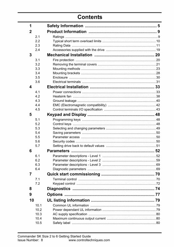
Contents1 Safety Information .............................................................. 52 Product Information ........................................................... 9
2.1 Ratings ....................................................................................................92.2 Typical short term overload limits ..........................................................102.3 Rating Data ...........................................................................................112.4 Accessories supplied with the drive ......................................................19
3 Mechanical Installation .................................................... 203.1 Fire protection .......................................................................................203.2 Removing the terminal covers ...............................................................213.3 Mounting methods .................................................................................233.4 Mounting brackets .................................................................................283.5 Enclosure ..............................................................................................303.6 Electrical terminals ................................................................................31
4 Electrical Installation ........................................................ 334.1 Power connections ................................................................................334.2 Heatsink fan ..........................................................................................384.3 Ground leakage .....................................................................................404.4 EMC (Electromagnetic compatibility) ....................................................424.5 Control terminals I/O specification ........................................................43
5 Keypad and Display .......................................................... 485.1 Programming keys ................................................................................485.2 Control keys ..........................................................................................485.3 Selecting and changing parameters ......................................................495.4 Saving parameters ................................................................................505.5 Parameter access .................................................................................505.6 Security codes .......................................................................................505.7 Setting drive back to default values ......................................................51
6 Parameters ........................................................................ 526.1 Parameter descriptions - Level 1 ..........................................................526.2 Parameter descriptions - Level 2 ..........................................................596.3 Parameter descriptions - Level 3 ..........................................................696.4 Diagnostic parameters ..........................................................................69
7 Quick start commissioning .............................................. 707.1 Terminal control ....................................................................................707.2 Keypad control ......................................................................................72
8 Diagnostics ....................................................................... 749 Options .............................................................................. 7710 UL listing information ....................................................... 79
10.1 Common UL information .......................................................................7910.2 Power dependant UL information ..........................................................7910.3 AC supply specification .........................................................................8010.4 Maximum continuous output current .....................................................8010.5 Safety label ...........................................................................................80
4 Commander SK Size 2 to 6 Getting Started Guidewww.controltechniques.com Issue Number: 8
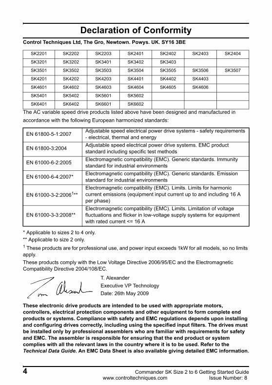
Declaration of ConformityControl Techniques Ltd, The Gro, Newtown. Powys. UK. SY16 3BE
The AC variable speed drive products listed above have been designed and manufactured in accordance with the following European harmonized standards:
* Applicable to sizes 2 to 4 only.** Applicable to size 2 only.1 These products are for professional use, and power input exceeds 1kW for all models, so no limits apply.These products comply with the Low Voltage Directive 2006/95/EC and the Electromagnetic Compatibility Directive 2004/108/EC.
These electronic drive products are intended to be used with appropriate motors, controllers, electrical protection components and other equipment to form complete end products or systems. Compliance with safety and EMC regulations depends upon installing and configuring drives correctly, including using the specified input filters. The drives must be installed only by professional assemblers who are familiar with requirements for safety and EMC. The assembler is responsible for ensuring that the end product or system complies with all the relevant laws in the country where it is to be used. Refer to the Technical Data Guide. An EMC Data Sheet is also available giving detailed EMC information.
SK2201 SK2202 SK2203 SK2401 SK2402 SK2403 SK2404
SK3201 SK3202 SK3401 SK3402 SK3403
SK3501 SK3502 SK3503 SK3504 SK3505 SK3506 SK3507
SK4201 SK4202 SK4203 SK4401 SK4402 SK4403
SK4601 SK4602 SK4603 SK4604 SK4605 SK4606
SK5401 SK5402 SK5601 SK5602
SK6401 SK6402 SK6601 SK6602
EN 61800-5-1:2007 Adjustable speed electrical power drive systems - safety requirements - electrical, thermal and energy
EN 61800-3:2004 Adjustable speed electrical power drive systems. EMC product standard including specific test methods
EN 61000-6-2:2005 Electromagnetic compatibility (EMC). Generic standards. Immunity standard for industrial environments
EN 61000-6-4:2007* Electromagnetic compatibility (EMC). Generic standards. Emission standard for industrial environments
EN 61000-3-2:20061**Electromagnetic compatibility (EMC). Limits. Limits for harmonic current emissions (equipment input current up to and including 16 A per phase)
EN 61000-3-3:2008**Electromagnetic compatibility (EMC). Limits. Limitation of voltage fluctuations and flicker in low-voltage supply systems for equipment with rated current <= 16 A
T. AlexanderExecutive VP TechnologyDate: 26th May 2009
Safety Inform
ationProduct
Information
Mechanical
InstallationElectrical
InstallationKeypad and
Display
Parameters
Quick start
comm
issioningD
iagnosticsO
ptionsU
L listing inform
ation
1 Safety Information
1.1 Warnings, Cautions and Notes
1.2 Electrical safety - general warningThe voltages used in the drive can cause severe electrical shock and/or burns, and could be lethal. Extreme care is necessary at all times when working with or adjacent to the drive.Specific warnings are given at the relevant places in this Guide.
1.3 System design and safety of personnelThe drive is intended as a component for professional incorporation into complete equipment or system. If installed incorrectly, the drive may present a safety hazard.The drive uses high voltages and currents, carries a high level of stored electrical energy, and is used to control equipment which can cause injury.System design, installation, commissioning / start-up and maintenance must be carried out by personnel who have the necessary training and experience. They must read this safety information and this guide carefully.The STOP and START controls or electrical inputs of the drive must not be relied upon to ensure safety of personnel. They do not isolate dangerous voltages from the output of the drive or from any external option unit. The supply must be disconnected by an approved electrical isolation device before gaining access to the electrical connections.The drive is not intended to be used for safety-related functions.Careful consideration must be given to the function of the drive which might result in a hazard, either through its intended behaviour or through incorrect operation due to a fault. In any application where a malfunction of the drive or its control system could lead to or allow damage, loss or injury, a risk analysis must be carried out, and where necessary, further measures taken to reduce the risk - for example, an over-speed protection device in case of failure of the speed control, or a fail-safe mechanical brake in case of loss of motor braking.
A Warning contains information, which is essential for avoiding a safety hazard.WARNING
A Caution contains information, which is necessary for avoiding a risk of damage to the product or other equipment.
CAUTION
A Note contains information which helps to ensure correct operation of the product.NOTE
Commander SK Size 2 to 6 Getting Started Guide 5Issue Number: 8 www.controltechniques.com
1.4 Environmental limitsInstructions within the supplied data and information within the Commander SK Technical Data Guide regarding transport, storage, installation and the use of the drive must be complied with, including the specified environmental limits. Drives must not be subjected to excessive physical force.
1.5 AccessAccess must be restricted to authorized personnel only. Safety regulations which apply at the place of use must be complied with.The IP (Ingress Protection) rating of the drive is installation dependant. For further information, refer to the Commander SK Technical Data Guide.
1.6 Fire protectionThe drive enclosure is not classified as a fire enclosure. A separate fire enclosure must be provided. For further information, refer to section 3.1 Fire protection on page 20.
1.7 Compliance with regulationsThe installer is responsible for complying with all relevant regulations, such as national wiring regulations, accident prevention regulations and electromagnetic compatibility (EMC) regulations. Particular attention must be given to the cross-sectional areas of conductors, the selection of fuses and other protection, and protective ground (earth) connections.The Commander SK Technical Data Guide contains instructions for achieving compliance with specific EMC standards.Within the European Union, all machinery in which this product is used must comply with the following directives:
2006/42/EC: Safety of machinery2004/108/EC: Electromagnetic compatibility
1.8 MotorEnsure the motor is installed in accordance with the manufacturer's recommendations. Ensure the motor shaft is not exposed.Standard squirrel cage induction motors are designed for single speed operation. If it is intended to use the capability of a drive to run a motor at speeds above its designed maximum, it is strongly recommended that the manufacturer is consulted first.Low speeds may cause the motor to overheat because the cooling fan becomes less effective. The motor should be installed with a protection thermistor. If necessary, an electric force vent fan should be used.The values of the motor parameters set in the drive affect the protection of the motor. The default values in the drive should not be relied upon.It is essential that the correct value is entered into parameter 06, motor rated current. This affects the thermal protection of the motor.
6 Commander SK Size 2 to 6 Getting Started Guidewww.controltechniques.com Issue Number: 8
Safety Inform
ationProduct
Information
Mechanical
InstallationElectrical
InstallationKeypad and
Display
Parameters
Quick start
comm
issioningD
iagnosticsO
ptionsU
L listing inform
ation
1.9 Mechanical brake controlThe brake control functions are provided to allow well co-ordinated operation of an external brake with the drive. While both hardware and software are designed to high standards of quality and robustness, they are not intended for use as safety functions, i.e. where a fault or failure would result in a risk of injury. In any application where the incorrect operation of the brake release mechanism could result in injury, independent protection devices of proven integrity must also be incorporated.
1.10 Adjusting parametersSome parameters have a profound effect on the operation of the drive. They must not be altered without careful consideration of the impact on the controlled system. Measures must be taken to prevent unwanted changes due to error or tampering.
1.11 Electrical installation1.11.1 Electric shock risk
The voltages present in the following locations can cause severe electric shock and may be lethal:• AC supply cables and connections• DC bus, dynamic brake cables and connections• Output cables and connections• Many internal parts of the drive, and external option unitsUnless otherwise indicated, control terminals are single insulated and must not be touched.
1.11.2 Isolation device The AC supply must be disconnected from the drive using an approved isolation device before any cover is removed from the drive or before any servicing work is performed.
1.11.3 STOP functionThe STOP function does not remove dangerous voltages from the drive, the motor or any external option units.
1.11.4 Stored chargeThe drive contains capacitors that remain charged to a potentially lethal voltage after the AC supply has been disconnected. If the drive has been energized, the AC supply must be isolated at least ten minutes before work may continue.Normally, the capacitors are discharged by an internal resistor. Under certain, unusual fault conditions, it is possible that the capacitors may fail to discharge, or be prevented from being discharged by a voltage applied to the output terminals. If the drive has failed in a manner that causes the display to go blank immediately, it is possible the capacitors will not be discharged. In this case, consult Control Techniques or their authorized distributor.
1.11.5 Equipment supplied by plug and socketSpecial attention must be given if the drive is installed in equipment which is connected to the AC supply by a plug and socket. The AC supply terminals of the drive are connected to the internal capacitors through rectifier diodes which are not intended to give safety isolation. If the plug terminals can be touched when the plug is disconnected from the socket, a means of automatically isolating the plug from the drive must be used (e.g. a latching relay).
Commander SK Size 2 to 6 Getting Started Guide 7Issue Number: 8 www.controltechniques.com
1.11.6 Ground leakage currentThe drive is supplied with an internal EMC filter capacitor installed. If the input voltage to the drive is supplied through an ELCB or RCD, these may trip due to the ground leakage current. See section 4.3.1 Internal EMC filter on page 40 for further information and how to disconnect the internal EMC capacitor.
1.12 Mechanical installation1.12.1 Lifting the drive
The weights of the model sizes 4, 5 and 6 are as follows:Size 4: 30kg (66Ibs)Size 5: 55kg (121Ibs)Size 6: 75kg (165Ibs)Use appropriate safeguards when lifting these models.
8 Commander SK Size 2 to 6 Getting Started Guidewww.controltechniques.com Issue Number: 8
Safety Information
Product Inform
ationM
echanical Installation
Electrical Installation
Keypad and D
isplayParam
etersQ
uick start com
missioning
Diagnostics
Options
UL listing
information
2 Product Information
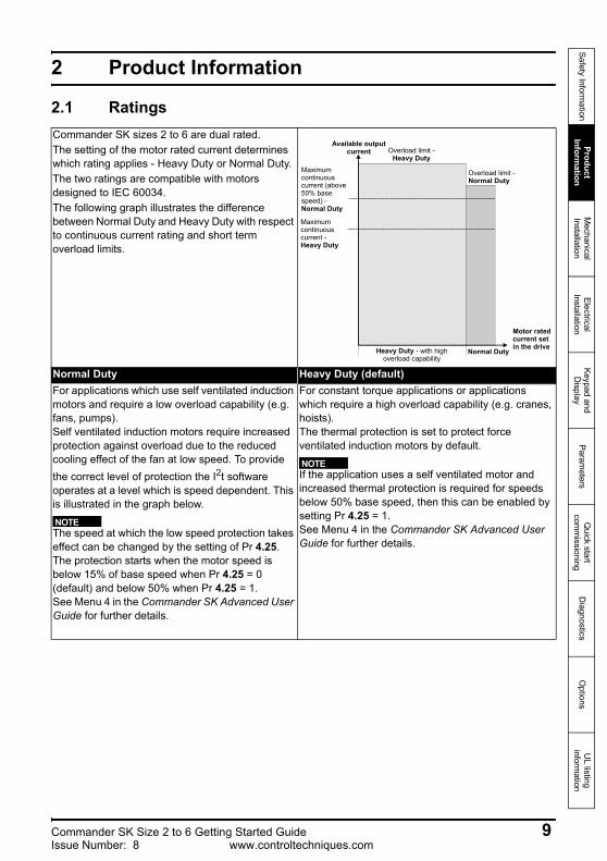
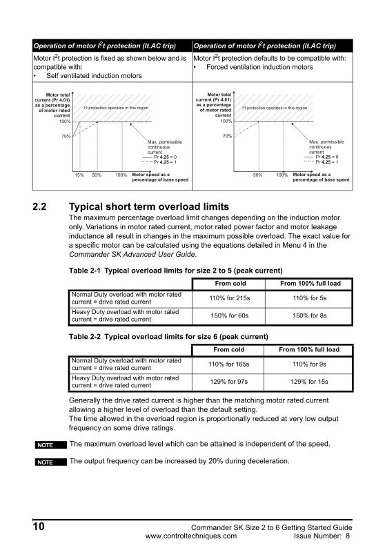
2.1 RatingsCommander SK sizes 2 to 6 are dual rated.The setting of the motor rated current determines which rating applies - Heavy Duty or Normal Duty.The two ratings are compatible with motors designed to IEC 60034.The following graph illustrates the difference between Normal Duty and Heavy Duty with respect to continuous current rating and short term overload limits.
Normal Duty Heavy Duty (default)For applications which use self ventilated induction motors and require a low overload capability (e.g. fans, pumps).Self ventilated induction motors require increased protection against overload due to the reduced cooling effect of the fan at low speed. To provide the correct level of protection the I2t software operates at a level which is speed dependent. This is illustrated in the graph below.
The speed at which the low speed protection takes effect can be changed by the setting of Pr 4.25. The protection starts when the motor speed is below 15% of base speed when Pr 4.25 = 0 (default) and below 50% when Pr 4.25 = 1.See Menu 4 in the Commander SK Advanced User Guide for further details.
For constant torque applications or applications which require a high overload capability (e.g. cranes, hoists).The thermal protection is set to protect force ventilated induction motors by default.
If the application uses a self ventilated motor and increased thermal protection is required for speeds below 50% base speed, then this can be enabled by setting Pr 4.25 = 1.See Menu 4 in the Commander SK Advanced User Guide for further details.
Available outputcurrent Overload limit -
Heavy DutyMaximum continuous current (above50% base speed) -Normal Duty
Maximum continuous current - Heavy Duty
Motor ratedcurrent setin the driveHeavy Duty - with high
overload capabilityNormal Duty
Overload limit -Normal Duty
NOTE
NOTE
Commander SK Size 2 to 6 Getting Started Guide 9Issue Number: 8 www.controltechniques.com
2.2 Typical short term overload limitsThe maximum percentage overload limit changes depending on the induction motor only. Variations in motor rated current, motor rated power factor and motor leakage inductance all result in changes in the maximum possible overload. The exact value for a specific motor can be calculated using the equations detailed in Menu 4 in the Commander SK Advanced User Guide.
Table 2-1 Typical overload limits for size 2 to 5 (peak current)
Table 2-2 Typical overload limits for size 6 (peak current)
Generally the drive rated current is higher than the matching motor rated current allowing a higher level of overload than the default setting. The time allowed in the overload region is proportionally reduced at very low output frequency on some drive ratings.
Operation of motor I2t protection (It.AC trip) Operation of motor I2t protection (It.AC trip)
Motor I2t protection is fixed as shown below and is compatible with:• Self ventilated induction motors
Motor I2t protection defaults to be compatible with:• Forced ventilation induction motors
Motor totalcurrent (Pr 4.01)as a percentage
of motor ratedcurrent
Motor speed as a percentage of base speed
100%
Max. permissiblecontinuouscurrent
100%
I t protection operates in this region2
70%
50%15%
Pr = 0Pr = 1
4.254.25
Motor totalcurrent (Pr 4.01)as a percentage
of motor ratedcurrent
Motor speed as a percentage of base speed
100%
Max. permissiblecontinuouscurrent
100%
I t protection operates in this region2
70%
50%
Pr = 0Pr = 1
4.254.25
From cold From 100% full loadNormal Duty overload with motor rated current = drive rated current 110% for 215s 110% for 5s
Heavy Duty overload with motor rated current = drive rated current 150% for 60s 150% for 8s
From cold From 100% full loadNormal Duty overload with motor rated current = drive rated current 110% for 165s 110% for 9s
Heavy Duty overload with motor rated current = drive rated current 129% for 97s 129% for 15s
The maximum overload level which can be attained is independent of the speed.NOTE
The output frequency can be increased by 20% during deceleration.NOTE
10 Commander SK Size 2 to 6 Getting Started Guidewww.controltechniques.com Issue Number: 8
Safety Information
Product Inform
ationM
echanical Installation
Electrical Installation
Keypad and D
isplayParam
etersQ
uick start com
missioning
Diagnostics
Options
UL listing
information
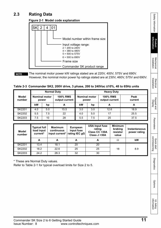
2.3 Rating DataFigure 2-1 Model code explanation
Table 2-3 Commander SK2, 200V drive, 3 phase, 200 to 240Vac ±10%, 48 to 65Hz units
* These are Normal Duty values.Refer to Table 2-1 for typical overload limits for Size 2 to 5.
SK 2 4 01
Model number within frame size
Input voltage range:2 = 200 to 240V4 = 380 to 480V5 = 500 to 575V6 = 500 to 690V
Frame size
Commander SK product range
The nominal motor power kW ratings stated are at 220V, 400V, 575V and 690V. However, the nominal motor power hp ratings stated are at 230V, 460V, 575V and 690V.
NOTE
Model number
Normal Duty Heavy Duty
Nominal motor power
100% RMS output current
Nominal motor power
100% RMS output current
Peak current
kW hp A kW hp A ASK2201 4.0 5.0 15.5 3.0 3.0 12.6 18.9SK2202 5.5 7.5 22 4.0 5.0 17 25.5SK2203 7.5 10 28 5.5 7.5 25 37.5
Model number
Typical full load input current*
Maximum continuous
input current*
European input fuse
rating IEC gG
USA Input fuse rating
Class CC <30AClass J >30A
Minimum braking resistor
value
Instantaneous power rating
A A A A Ω kWSK2201 13.4 18.1 20 20
18 8.9SK2202 18.2 22.6 25 25SK2203 24.2 28.3 32 30
Commander SK Size 2 to 6 Getting Started Guide 11Issue Number: 8 www.controltechniques.com
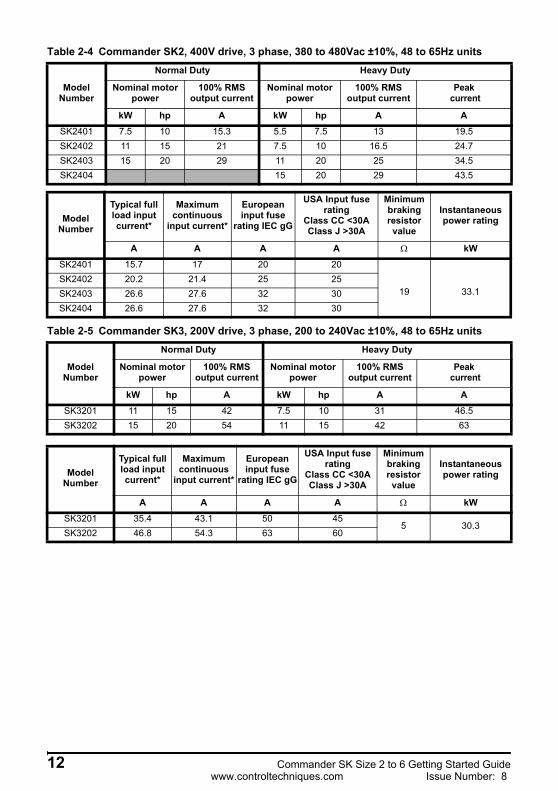
Table 2-4 Commander SK2, 400V drive, 3 phase, 380 to 480Vac ±10%, 48 to 65Hz units
Table 2-5 Commander SK3, 200V drive, 3 phase, 200 to 240Vac ±10%, 48 to 65Hz units
Model Number
Normal Duty Heavy Duty
Nominal motor power
100% RMS output current
Nominal motor power
100% RMS output current
Peak current
kW hp A kW hp A ASK2401 7.5 10 15.3 5.5 7.5 13 19.5SK2402 11 15 21 7.5 10 16.5 24.7SK2403 15 20 29 11 20 25 34.5SK2404 15 20 29 43.5
Model Number
Typical full load input current*
Maximum continuous
input current*
European input fuse
rating IEC gG
USA Input fuse rating
Class CC <30AClass J >30A
Minimum braking resistor
value
Instantaneous power rating
A A A A Ω kWSK2401 15.7 17 20 20
19 33.1SK2402 20.2 21.4 25 25SK2403 26.6 27.6 32 30SK2404 26.6 27.6 32 30
Model Number
Normal Duty Heavy Duty
Nominal motor power
100% RMS output current
Nominal motor power
100% RMS output current
Peak current
kW hp A kW hp A ASK3201 11 15 42 7.5 10 31 46.5SK3202 15 20 54 11 15 42 63
Model Number
Typical full load input current*
Maximum continuous
input current*
European input fuse
rating IEC gG
USA Input fuse rating
Class CC <30AClass J >30A
Minimum braking resistor
value
Instantaneous power rating
A A A A Ω kWSK3201 35.4 43.1 50 45
5 30.3SK3202 46.8 54.3 63 60
12 Commander SK Size 2 to 6 Getting Started Guidewww.controltechniques.com Issue Number: 8
Safety Information
Product Inform
ationM
echanical Installation
Electrical Installation
Keypad and D
isplayParam
etersQ
uick start com
missioning
Diagnostics
Options
UL listing
information
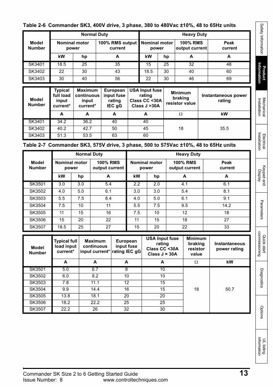
Table 2-6 Commander SK3, 400V drive, 3 phase, 380 to 480Vac ±10%, 48 to 65Hz units
Table 2-7 Commander SK3, 575V drive, 3 phase, 500 to 575Vac ±10%, 48 to 65Hz units
Model Number
Normal Duty Heavy Duty
Nominal motor power
100% RMS output current
Nominal motor power
100% RMS output current
Peak current
kW hp A kW hp A ASK3401 18.5 25 35 15 25 32 48SK3402 22 30 43 18.5 30 40 60SK3403 30 40 56 22 30 46 69
Model Number
Typical full load
input current*
Maximum continuous
input current*
European input fuse
rating IEC gG
USA Input fuse rating
Class CC <30AClass J >30A
Minimum braking
resistor value Instantaneous power
rating
A A A A Ω kWSK3401 34.2 36.2 40 40
18 35.5SK3402 40.2 42.7 50 45SK3403 51.3 53.5 63 60
Model Number
Normal Duty Heavy Duty
Nominal motor power
100% RMS output current
Nominal motor power
100% RMS output current
Peak current
kW hp A kW hp A ASK3501 3.0 3.0 5.4 2.2 2.0 4.1 6.1SK3502 4.0 5.0 6.1 3.0 3.0 5.4 8.1SK3503 5.5 7.5 8.4 4.0 5.0 6.1 9.1SK3504 7.5 10 11 5.5 7.5 9.5 14.2SK3505 11 15 16 7.5 10 12 18SK3506 15 20 22 11 15 18 27SK3507 18.5 25 27 15 20 22 33
Model Number
Typical full load input current*
Maximum continuous
input current*
European input fuse
rating IEC gG
USA Input fuse rating
Class CC <30AClass J = 30A
Minimum braking resistor value
Instantaneous power rating
A A A A Ω kWSK3501 5.0 6.7 8 10
18 50.7
SK3502 6.0 8.2 10 10SK3503 7.8 11.1 12 15SK3504 9.9 14.4 16 15SK3505 13.8 18.1 20 20SK3506 18.2 22.2 25 25SK3507 22.2 26 32 30
Commander SK Size 2 to 6 Getting Started Guide 13Issue Number: 8 www.controltechniques.com

Table 2-8 Commander SK4, 200V drive, 3 phase, 200 to 240Vac ±10%, 48 to 65Hz units
Table 2-9 Commander SK4, 400V drive, 3 phase, 380 to 480Vac ±10%, 48 to 65Hz units
* These are Normal Duty values.** Semi conductor fuse in series with HRC fuse or circuit breaker.
Model number
Normal Duty Heavy Duty
Nominal motor power
100% RMS output current Nominal motor power 100% RMS
output currentPeak
current
kW hp A kW hp A ASK4201 18.5 25 68 15 20 56 84SK4202 22 30 80 18.5 25 68 102SK4203 30 40 104 22 30 80 120
Model number
Typical full load
input current*
Maximum continuous
input current*
Fuse option 1 Fuse option 2**Minimum braking resistor value
Instantaneous power rating
European input fuse
rating IEC gR
USA Input fuse rating Ferraz HSJ
HRCIEC class
gGUL class J
Semi-conductorIEC class
aR
A A A A A A Ω kWSK4201 62.1 68.9 100 90 90 160
5 30.3SK4202 72.1 78.1 100 100 100 160SK4203 94.5 99.9 125 125 125 200
Model number
Normal Duty Heavy Duty
Nominal motor power
100% RMS output current Nominal motor power 100% RMS
output currentPeak
current
kW hp A kW hp A ASK4401 37 50 68 30 50 60 90SK4402 45 60 83 37 60 74 111SK4403 55 75 104 45 75 96 144
Model number
Typical full load
input current*
Maximum continuous
input current*
Fuse option 1 Fuse option 2**Minimum braking resistor value
Instantaneous power rating
European input fuse
rating IEC gR
USA Input fuse rating Ferraz HSJ
HRCIEC class
gGUL class J
Semi-conductorIEC class
aR
A A A A A A Ω kWSK4401 61.2 62.3 80 80 80 160
11 55.3SK4402 76.3 79.6 110 110 100 200SK4403 94.1 97.2 125 125 125 200 9 67.6
The Commander SK size 4 to 6 cannot be used on single-phase supplies due to the half-controlled input stage on these drives.
NOTE
14 Commander SK Size 2 to 6 Getting Started Guidewww.controltechniques.com Issue Number: 8
Safety Information
Product Inform
ationM
echanical Installation
Electrical Installation
Keypad and D
isplayParam
etersQ
uick start com
missioning
Diagnostics
Options
UL listing
information
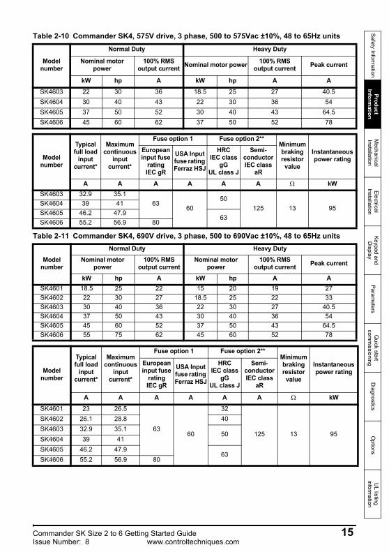
Table 2-10 Commander SK4, 575V drive, 3 phase, 500 to 575Vac ±10%, 48 to 65Hz units
Table 2-11 Commander SK4, 690V drive, 3 phase, 500 to 690Vac ±10%, 48 to 65Hz units
Model number
Normal Duty Heavy Duty
Nominal motor power
100% RMS output current Nominal motor power 100% RMS
output current Peak current
kW hp A kW hp A ASK4603 22 30 36 18.5 25 27 40.5SK4604 30 40 43 22 30 36 54SK4605 37 50 52 30 40 43 64.5SK4606 45 60 62 37 50 52 78
Model number
Typical full load
input current*
Maximum continuous
input current*
Fuse option 1 Fuse option 2**Minimum braking resistor value
Instantaneous power rating
European input fuse
rating IEC gR
USA Input fuse rating Ferraz HSJ
HRCIEC class
gGUL class J
Semi-conductorIEC class
aR
A A A A A A Ω kWSK4603 32.9 35.1
6360
50125 13 95
SK4604 39 41SK4605 46.2 47.9
63SK4606 55.2 56.9 80
Model number
Normal Duty Heavy DutyNominal motor
power100% RMS
output currentNominal motor
power100% RMS
output current Peak current
kW hp A kW hp A ASK4601 18.5 25 22 15 20 19 27SK4602 22 30 27 18.5 25 22 33SK4603 30 40 36 22 30 27 40.5SK4604 37 50 43 30 40 36 54SK4605 45 60 52 37 50 43 64.5SK4606 55 75 62 45 60 52 78
Model number
Typical full load
input current*
Maximum continuous
input current*
Fuse option 1 Fuse option 2**Minimum braking resistor value
Instantaneous power rating
European input fuse
rating IEC gR
USA Input fuse rating Ferraz HSJ
HRCIEC class
gGUL class J
Semi-conductorIEC class
aR
A A A A A A Ω kWSK4601 23 26.5
6360
32
125 13 95
SK4602 26.1 28.8 40SK4603 32.9 35.1
50SK4604 39 41SK4605 46.2 47.9
63SK4606 55.2 56.9 80
Commander SK Size 2 to 6 Getting Started Guide 15Issue Number: 8 www.controltechniques.com

Table 2-12 Commander SK5, 400V drive, 3 phase, 380 to 480Vac ±10%, 48 to 65Hz units
Table 2-13 Commander SK5, 575V drive, 3 phase, 500 to 575Vac ±10%, 48 to 65Hz units
* These are Normal Duty values.** Semi conductor fuse in series with HRC fuse or circuit breaker.
Model number
Normal Duty Heavy Duty
Nominal motor power
100% RMS output current Nominal motor power 100% RMS output
current Peak current
kW hp A kW hp A ASK5401 75 100 138 55 100 124 186SK5402 90 125 168 75 125 156 234
Model number
Typical full load
input current*
Maximum continuous
input current*
Fuse option 1 Fuse option 2**Minimum braking resistor value
Instantaneous power rating
European input fuse
rating IEC gR
USA Input fuse rating Ferraz HSJ
HRCIEC class
gGUL class J
Semi-conductorIEC class
aR
A A A A A A Ω kWSK5401 126 131 200 175 160 200
7 86.9SK5402 152 156 250 225 200 250
Model number
Normal Duty Heavy Duty
Nominal motor power
100% RMS output current Nominal motor power 100% RMS output
current Peak current
kW hp A kW hp A ASK5601 55 75 84 45 60 63 93SK5602 75 100 99 55 75 85 126
Model number
Typical full load
input current*
Maximum continuous
input current*
Fuse option 1 Fuse option 2**Minimum braking resistor value
Instantaneous power rating
European input fuse
rating IEC gR
USA Input fuse rating Ferraz HSJ
HRCIEC class
gGUL class J
Semi-conductorIEC class
aR
A A A A A A Ω kWSK5601 75.5 82.6
125 10090
160 10 125.4SK5602 89.1 94.8 125
16 Commander SK Size 2 to 6 Getting Started Guidewww.controltechniques.com Issue Number: 8

Safety Information
Product Inform
ationM
echanical Installation
Electrical Installation
Keypad and D
isplayParam
etersQ
uick start com
missioning
Diagnostics
Options
UL listing
information
Table 2-14 Commander SK5, 690V drive, 3 phase, 500 to 690Vac ±10%, 48 to 65Hz units
Table 2-15 Commander SK6, 400V drive, 3 phase, 380 to 480Vac ±10%, 48 to 65Hz units
Model number
Normal Duty Heavy Duty
Nominal motor power
100% RMS output current Nominal motor power 100% RMS output
current Peak current
kW hp A kW hp A ASK5601 75 100 84 55 75 63 93SK5602 90 125 99 75 100 85 126
Model number
Typical full load
input current*
Maximum continuous
input current*
Fuse option 1 Fuse option 2**Minimum braking resistor value
Instantaneous power rating
European input fuse
rating IEC gR
USA Input fuse rating Ferraz HSJ
HRCIEC class
gGUL class J
Semi-conductorIEC class
aR
A A A A A A Ω kWSK5601 75.5 82.6
125 10090
160 10 125.4SK5602 89.1 94.8 125
Model number
Normal Duty Heavy Duty
Nominal motor power
100% RMS output current Nominal motor power 100% RMS
output current Peak current
kW hp A kW hp A ASK6401 110 150 205 90 150 180 231SK6402 132 200 236 110 150 210 270
Model number
Typical full load
input current*
Maximum continuous
input current*
Fuse option 1 Fuse option 2**Minimum braking resistor value
Instantaneous power rating
European input fuse
rating IEC gR
USA Input fuse rating Ferraz HSJ
HRCIEC class
gGUL class J
Semi-conductorIEC class
aR
A A A A A A Ω kWSK6401 224 241 315 300 250 315
5 121.7SK6402 247 266 315 300 300 350
Commander SK Size 2 to 6 Getting Started Guide 17Issue Number: 8 www.controltechniques.com
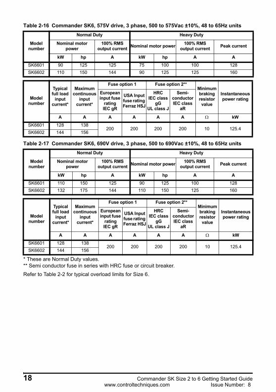
Table 2-16 Commander SK6, 575V drive, 3 phase, 500 to 575Vac ±10%, 48 to 65Hz units
Table 2-17 Commander SK6, 690V drive, 3 phase, 500 to 690Vac ±10%, 48 to 65Hz units
* These are Normal Duty values.** Semi conductor fuse in series with HRC fuse or circuit breaker.Refer to Table 2-2 for typical overload limits for Size 6.
Model number
Normal Duty Heavy Duty
Nominal motor power
100% RMS output current Nominal motor power 100% RMS
output current Peak current
kW hp A kW hp A ASK6601 90 125 125 75 100 100 128SK6602 110 150 144 90 125 125 160
Model number
Typical full load
input current*
Maximum continuous
input current*
Fuse option 1 Fuse option 2**Minimum braking resistor value
Instantaneous power rating
European input fuse
rating IEC gR
USA Input fuse rating Ferraz HSJ
HRCIEC class
gGUL class J
Semi-conductorIEC class
aR
A A A A A A Ω kWSK6601 128 138
200 200 200 200 10 125.4SK6602 144 156
Model number
Normal Duty Heavy Duty
Nominal motor power
100% RMS output current Nominal motor power 100% RMS
output current Peak current
kW hp A kW hp A ASK6601 110 150 125 90 125 100 128SK6602 132 175 144 110 150 125 160
Model number
Typical full load
input current*
Maximum continuous
input current*
Fuse option 1 Fuse option 2**Minimum braking resistor value
Instantaneous power rating
European input fuse
rating IEC gR
USA Input fuse rating Ferraz HSJ
HRCIEC class
gGUL class J
Semi-conductorIEC class
aR
A A A A A A Ω kWSK6601 128 138
200 200 200 200 10 125.4SK6602 144 156
18 Commander SK Size 2 to 6 Getting Started Guidewww.controltechniques.com Issue Number: 8
Safety Information
Product Inform
ationM
echanical Installation
Electrical Installation
Keypad and D
isplayParam
etersQ
uick start com
missioning
Diagnostics
Options
UL listing
information
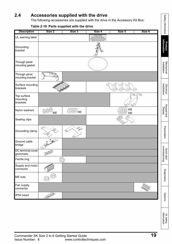
2.4 Accessories supplied with the driveThe following accessories are supplied with the drive in the Accessory Kit Box:
Table 2-18 Parts supplied with the driveDescription Size 2 Size 3 Size 4 Size 5 Size 6
UL warning label
Grounding bracket
Through panel mounting gasket
Through panel mounting bracket
Surface mounting brackets
Top surface mounting brackets
Nylon washers
Sealing clips
Grounding clamp
Ground cable bridge
DC terminal cover grommets
Ferrite ring
Supply and motor connector
M5 nuts
Fan supply connector
IP54 insert
CAUTIONRisk of Electric Shock
Power down unit 10minutesbefore removing cover
M6 M6 M6M8
Commander SK Size 2 to 6 Getting Started Guide 19Issue Number: 8 www.controltechniques.com
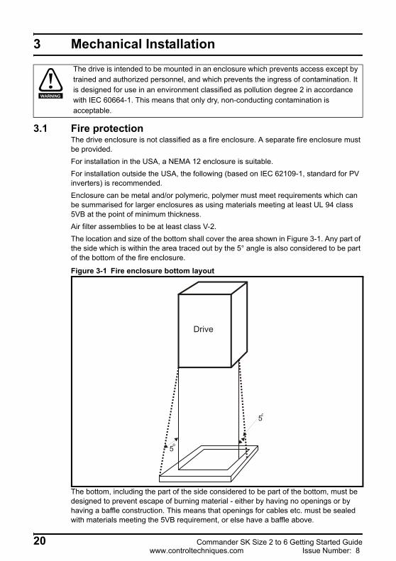
3 Mechanical Installation
3.1 Fire protectionThe drive enclosure is not classified as a fire enclosure. A separate fire enclosure must be provided.For installation in the USA, a NEMA 12 enclosure is suitable.For installation outside the USA, the following (based on IEC 62109-1, standard for PV inverters) is recommended.Enclosure can be metal and/or polymeric, polymer must meet requirements which can be summarised for larger enclosures as using materials meeting at least UL 94 class 5VB at the point of minimum thickness.Air filter assemblies to be at least class V-2.The location and size of the bottom shall cover the area shown in Figure 3-1. Any part of the side which is within the area traced out by the 5° angle is also considered to be part of the bottom of the fire enclosure.
Figure 3-1 Fire enclosure bottom layout
The bottom, including the part of the side considered to be part of the bottom, must be designed to prevent escape of burning material - either by having no openings or by having a baffle construction. This means that openings for cables etc. must be sealed with materials meeting the 5VB requirement, or else have a baffle above.
The drive is intended to be mounted in an enclosure which prevents access except by trained and authorized personnel, and which prevents the ingress of contamination. It is designed for use in an environment classified as pollution degree 2 in accordance with IEC 60664-1. This means that only dry, non-conducting contamination is acceptable.
WARNING
Drive
5o
5o
20 Commander SK Size 2 to 6 Getting Started Guidewww.controltechniques.com Issue Number: 8
Safety Information
Product Inform
ationM
echanical Installation
Electrical Installation
Keypad and D
isplayParam
etersQ
uick start com
missioning
Diagnostics
Options
UL listing
information
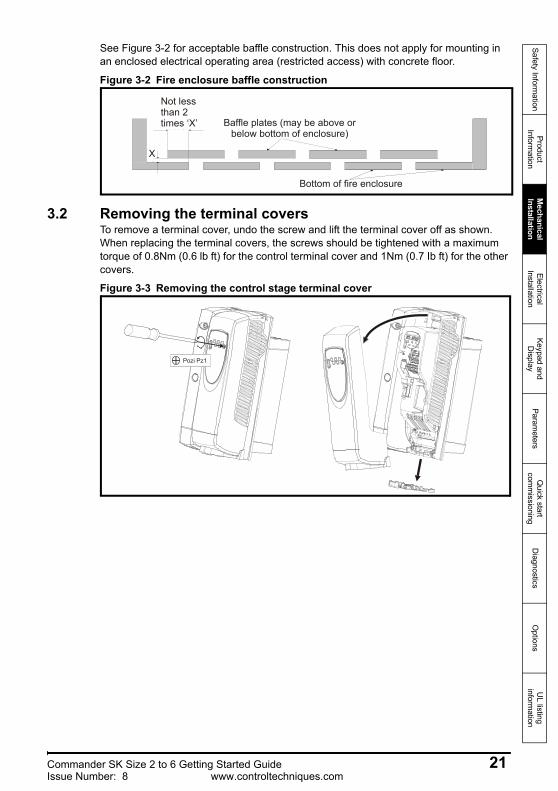
See Figure 3-2 for acceptable baffle construction. This does not apply for mounting in an enclosed electrical operating area (restricted access) with concrete floor.
Figure 3-2 Fire enclosure baffle construction
3.2 Removing the terminal coversTo remove a terminal cover, undo the screw and lift the terminal cover off as shown. When replacing the terminal covers, the screws should be tightened with a maximum torque of 0.8Nm (0.6 lb ft) for the control terminal cover and 1Nm (0.7 Ib ft) for the other covers.
Figure 3-3 Removing the control stage terminal cover
N o t l e s st h a n 2 X B a f f l e p l a t e s ( m a y b e
a b o v e o r b e l o w b o t t o mo f e n c l o s u r e )
X
B o t t o m o f f i r ee n c l o s u r e
Not lessthan 2 times ‘X’ Baffle plates (may be above or
below bottom of enclosure)
Bottom of fire enclosure
X
Pozi Pz1
Commander SK Size 2 to 6 Getting Started Guide 21Issue Number: 8 www.controltechniques.com
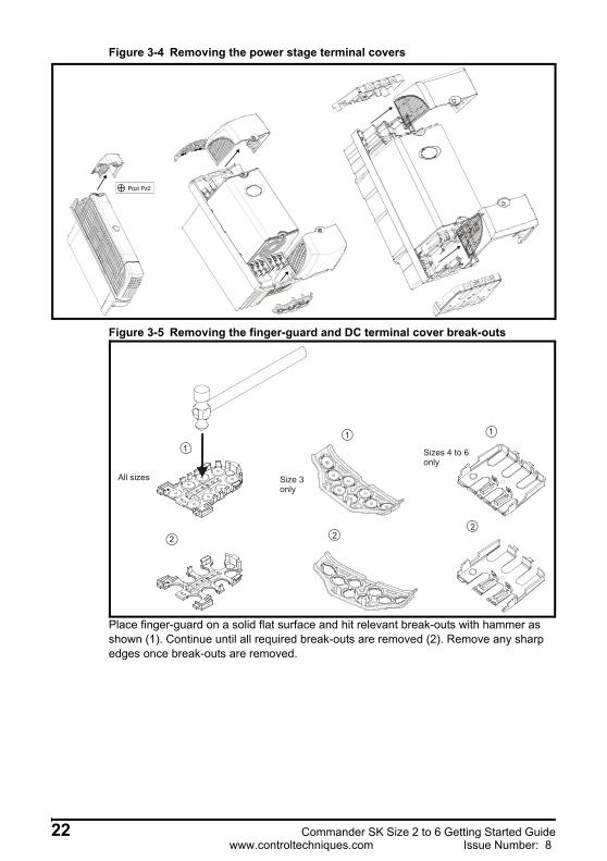
Figure 3-4 Removing the power stage terminal covers
Figure 3-5 Removing the finger-guard and DC terminal cover break-outs
Place finger-guard on a solid flat surface and hit relevant break-outs with hammer as shown (1). Continue until all required break-outs are removed (2). Remove any sharp edges once break-outs are removed.
Pozi Pz2
1
2
All sizes Size 3only
1
22
1
Sizes 4 to 6only
22 Commander SK Size 2 to 6 Getting Started Guidewww.controltechniques.com Issue Number: 8
Safety Information
Product Inform
ationM
echanical Installation
Electrical Installation
Keypad and D
isplayParam
etersQ
uick start com
missioning
Diagnostics
Options
UL listing
information
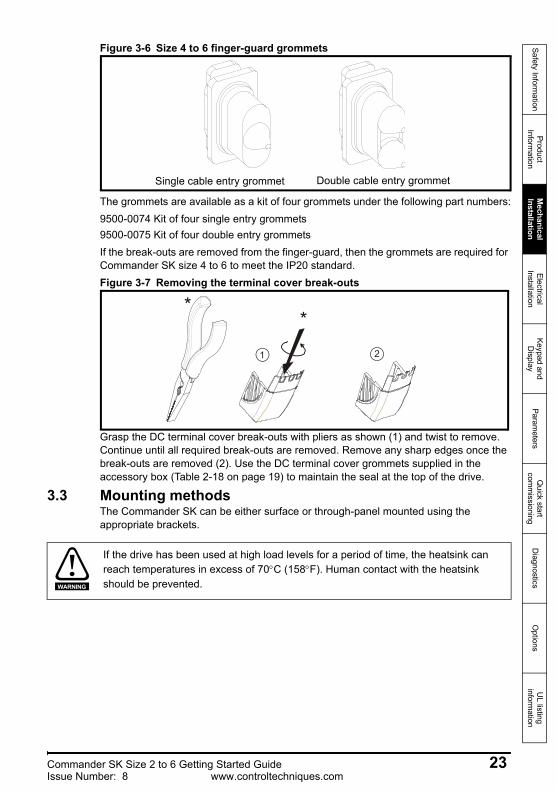
Figure 3-6 Size 4 to 6 finger-guard grommets
The grommets are available as a kit of four grommets under the following part numbers:9500-0074 Kit of four single entry grommets9500-0075 Kit of four double entry grommetsIf the break-outs are removed from the finger-guard, then the grommets are required for Commander SK size 4 to 6 to meet the IP20 standard.Figure 3-7 Removing the terminal cover break-outs
Grasp the DC terminal cover break-outs with pliers as shown (1) and twist to remove. Continue until all required break-outs are removed. Remove any sharp edges once the break-outs are removed (2). Use the DC terminal cover grommets supplied in the accessory box (Table 2-18 on page 19) to maintain the seal at the top of the drive.
3.3 Mounting methodsThe Commander SK can be either surface or through-panel mounted using the appropriate brackets.
Single cable entry grommet Double cable entry grommet
1 2
**
If the drive has been used at high load levels for a period of time, the heatsink can reach temperatures in excess of 70°C (158°F). Human contact with the heatsink should be prevented.WARNING
Commander SK Size 2 to 6 Getting Started Guide 23Issue Number: 8 www.controltechniques.com
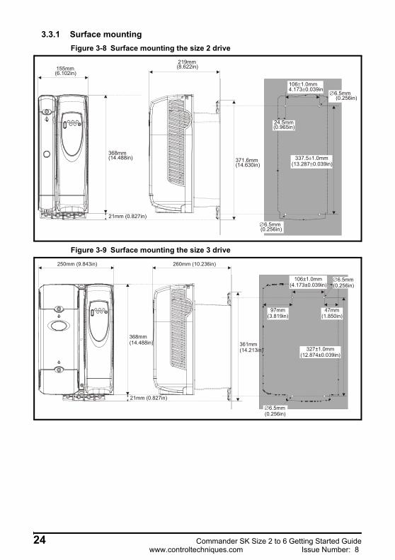
3.3.1 Surface mountingFigure 3-8 Surface mounting the size 2 drive
Figure 3-9 Surface mounting the size 3 drive
155mm(6.102in)
368mm(14.488in)
219mm(8.622in)
371.6mm(14.630in)
∅ 6.5mm (0.256in)
∅ 6.5mm (0.256in)
21mm (0.827in)
337.5 1.0mm±(13.287 0.039in)±
106 1.0mm±4.173 0.039in±
24.5mm(0.965in)
250mm (9.843in)
368mm(14.488in)
260mm (10.236in)
361mm(14.213in)
21mm (0.827in)
97mm(3.819in)
47mm(1.850in)
106±1.0mm(4.173±0.039in)
∅6.5mm(0.256in)
327±1.0mm(12.874±0.039in)
∅6.5mm(0.256in)
24 Commander SK Size 2 to 6 Getting Started Guidewww.controltechniques.com Issue Number: 8
Safety Information
Product Inform
ationM
echanical Installation
Electrical Installation
Keypad and D
isplayParam
etersQ
uick start com
missioning
Diagnostics
Options
UL listing
information
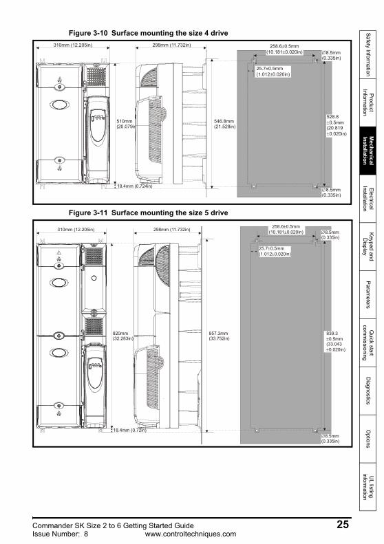
Figure 3-10 Surface mounting the size 4 drive
Figure 3-11 Surface mounting the size 5 drive
310mm (12.205in)
510mm(20.079in)
298mm (11.732in) 258.6 0.5mm(10.181 0.020in)
±±
528.80.5mm
(20.8190.020in)
±
±
546.8mm(21.528in)
18.4mm (0.724in)
25.7 0.5mm(1.012 0.020in)
±±
∅8.5mm(0.335in)
∅8.5mm(0.335in)
258.6 0.5mm(10.181 0.020in)
±±
25.7 0.5mm(1.012 0.020in)
±±
839.30.5mm
(33.0430.020in)
±
±
310mm (12.205in) 298mm (11.732in)
857.3mm(33.752in)
820mm(32.283in)
18.4mm (0.72in)
∅8.5mm(0.335in)
∅8.5mm(0.335in)
Commander SK Size 2 to 6 Getting Started Guide 25Issue Number: 8 www.controltechniques.com
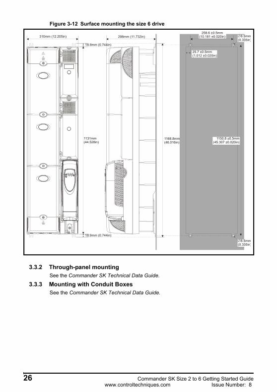
Figure 3-12 Surface mounting the size 6 drive
3.3.2 Through-panel mountingSee the Commander SK Technical Data Guide.
3.3.3 Mounting with Conduit BoxesSee the Commander SK Technical Data Guide.
310mm (12.205in)
18.9mm (0.744in)
18.9mm (0.744in)
1131mm(44.528in)
298mm (11.732in)
1168.8mm(46.016in)
25.7 0.5mm(1.012 0.020in)
±±
258.6 0.5mm(10.181 0.020in)
±± ∅8.5mm
(0.335in)
∅8.5mm(0.335in)
1150.8 ±0.5mm(45.307 0.020in)±
26 Commander SK Size 2 to 6 Getting Started Guidewww.controltechniques.com Issue Number: 8
Safety Information
Product Inform
ationM
echanical Installation
Electrical Installation
Keypad and D
isplayParam
etersQ
uick start com
missioning
Diagnostics
Options
UL listing
information
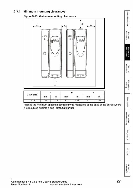
3.3.4 Minimum mounting clearancesFigure 3-13 Minimum mounting clearances
*This is the minimum spacing between drives measured at the base of the drives where it is mounted against a back plate/flat surface.
Drive sizeA B C
mm in mm in mm in2 to 6 30 1.18 30* 1.18* 100 3.94
BA A
C
C
Commander SK Size 2 to 6 Getting Started Guide 27Issue Number: 8 www.controltechniques.com
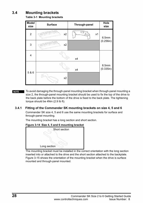
3.4 Mounting bracketsTable 3-1 Mounting brackets
3.4.1 Fitting of the Commander SK mounting brackets on size 4, 5 and 6Commander SK size 4, 5 and 6 use the same mounting brackets for surface and through-panel mounting.The mounting bracket has a long section and short section.
Figure 3-14 Size 4, 5 and 6 mounting bracket
The mounting bracket must be installed in the correct orientation with the long section inserted into or attached to the drive and the short section attached to the backplate. Figure 3-15 shows the orientation of the mounting bracket when the drive is surface mounted and through-panel mounted.
Model size Surface Through-panel Hole
size
2 x2 x16.5mm
(0.256in)3 x2
4x4
8.5mm(0.335in)
5 & 6x4
x2
To avoid damaging the through-panel mounting bracket when through-panel mounting a size 2, the through-panel mounting bracket should be used to fix the top of the drive to the back plate before the bottom of the drive is fixed to the back plate. The tightening torque should be 4Nm (2.9 Ib ft).
NOTE
Short section
Long section
28 Commander SK Size 2 to 6 Getting Started Guidewww.controltechniques.com Issue Number: 8
Safety Information
Product Inform
ationM
echanical Installation
Electrical Installation
Keypad and D
isplayParam
etersQ
uick start com
missioning
Diagnostics
Options
UL listing
information
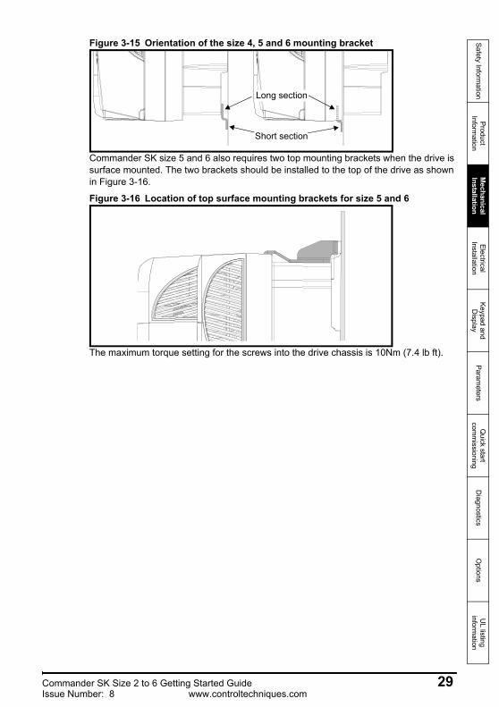
Figure 3-15 Orientation of the size 4, 5 and 6 mounting bracket
Commander SK size 5 and 6 also requires two top mounting brackets when the drive is surface mounted. The two brackets should be installed to the top of the drive as shown in Figure 3-16.
Figure 3-16 Location of top surface mounting brackets for size 5 and 6
The maximum torque setting for the screws into the drive chassis is 10Nm (7.4 lb ft).
Short section
Long section
Commander SK Size 2 to 6 Getting Started Guide 29Issue Number: 8 www.controltechniques.com
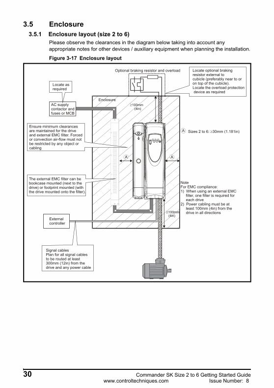
3.5 Enclosure3.5.1 Enclosure layout (size 2 to 6)
Please observe the clearances in the diagram below taking into account any appropriate notes for other devices / auxiliary equipment when planning the installation.
Figure 3-17 Enclosure layout
≥100mm(4in)
EnclosureAC supply contactor and fuses or MCB
Locate asrequiredLocate as required
Externalcontroller
Signal cablesPlan for all signal cablesto be routed at least300mm (12in) from thedrive and any power cable
Ensure minimum clearancesare maintained for the drive and external EMC filter. Forcedor convection air-flow must notbe restricted by any object orcabling
≥100mm(4in)
Optional braking resistor and overload Locate optional braking resistor external to cubicle (preferably near to or on top of the cubicle).Locate the overload protection device as required
The external EMC filter can be bookcase mounted (next to the drive) or footprint mounted (with the drive mounted onto the filter).
NoteFor EMC compliance:1) When using an external EMC filter, one filter is required for each drive2) Power cabling must be at least 100mm (4in) from the drive in all directions
A
A Sizes 2 to 6: 30mm (1.181in)≥
A
30 Commander SK Size 2 to 6 Getting Started Guidewww.controltechniques.com Issue Number: 8
Safety Information
Product Inform
ationM
echanical Installation
Electrical Installation
Keypad and D
isplayParam
etersQ
uick start com
missioning
Diagnostics
Options
UL listing
information
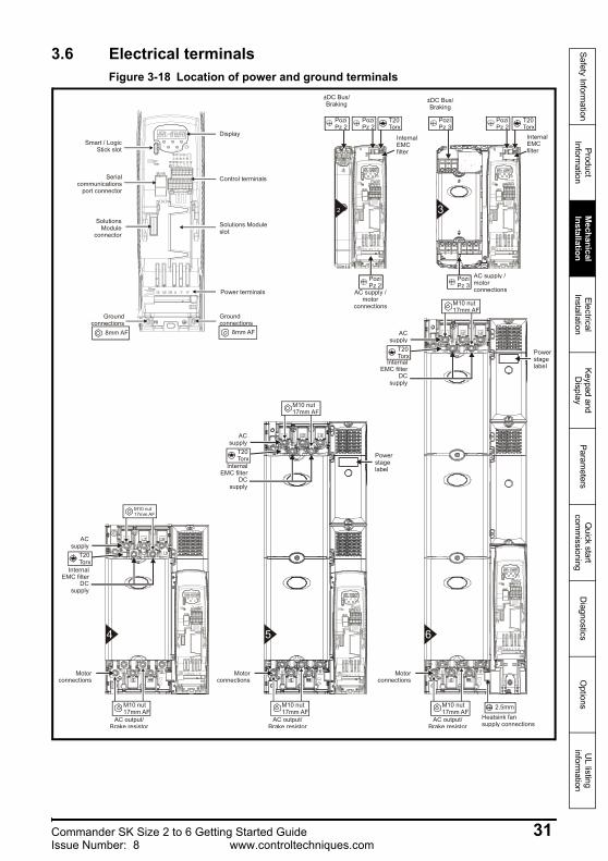
3.6 Electrical terminalsFigure 3-18 Location of power and ground terminals
2
Smart / LogicStick slot
Serial communications
port connector
Solutions Module
connector
AC supply / motor
connections
InternalEMCfilter
InternalEMCfilter
4
Motorconnections
AC supply
InternalEMC filter
DC supply
5
Motorconnections
6
Motorconnections
Heatsink fansupply connections
3
Powerstagelabel
Powerstagelabel
Groundconnections
8mm AF
Solutions Moduleslot
Display
Power terminals
Control terminals
Groundconnections
8mm AF
PoziPz 2
PoziPz 2
T20Torx
PoziPz 2
PoziPz 2PoziPz 3
PoziPz 2
T20Torx
PoziPz 2PoziPz 2
AC supply / motor connections
PoziPz 2PoziPz 3
M10 nut17mm AF
M10 nut17mm AF
M10 nut17mm AF
M10 nut17mm AF
AC output/Brake resistor
M10 nut17mm AF
AC output/Brake resistor
M10 nut17mm AF
AC output/Brake resistor
T20Torx
AC supply
InternalEMC filter
DC supply
T20Torx
AC supply
InternalEMC filter
DC supply
T20Torx
2.5mm
±DC Bus/Braking ±DC Bus/
Braking
Commander SK Size 2 to 6 Getting Started Guide 31Issue Number: 8 www.controltechniques.com
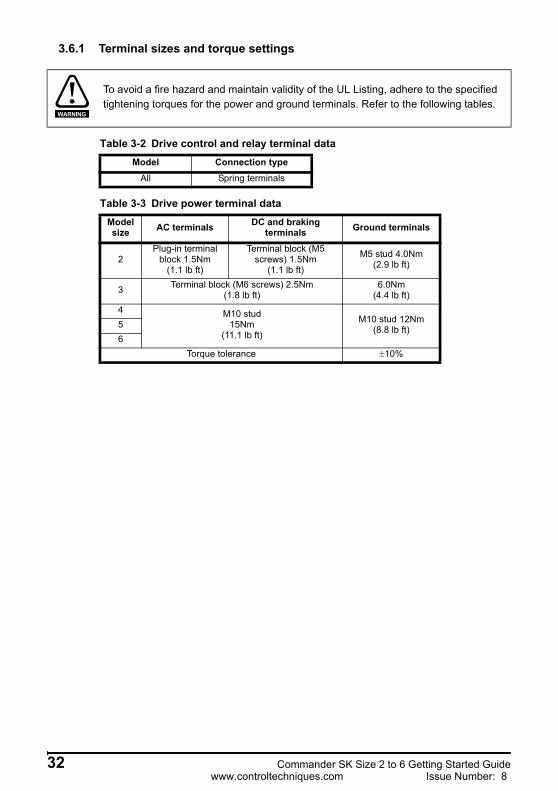
3.6.1 Terminal sizes and torque settings
Table 3-2 Drive control and relay terminal data
Table 3-3 Drive power terminal data
To avoid a fire hazard and maintain validity of the UL Listing, adhere to the specified tightening torques for the power and ground terminals. Refer to the following tables.
WARNING
Model Connection typeAll Spring terminals
Model size AC terminals DC and braking
terminals Ground terminals
2Plug-in terminal
block 1.5Nm(1.1 lb ft)
Terminal block (M5 screws) 1.5Nm
(1.1 lb ft)
M5 stud 4.0Nm(2.9 lb ft)
3 Terminal block (M6 screws) 2.5Nm(1.8 lb ft)
6.0Nm(4.4 lb ft)
4 M10 stud15Nm
(11.1 lb ft)
M10 stud 12Nm(8.8 lb ft)5
6Torque tolerance ±10%
32 Commander SK Size 2 to 6 Getting Started Guidewww.controltechniques.com Issue Number: 8
Safety Information
Product Inform
ationM
echanical Installation
Electrical Installation
Keypad and D
isplayParam
etersQ
uick start com
missioning
Diagnostics
Options
UL listing
information
4 Electrical Installation4.1 Power connections
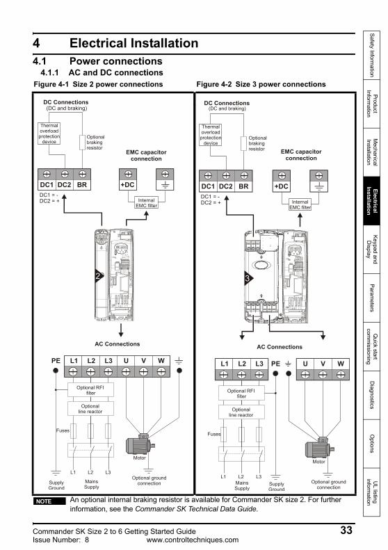
4.1.1 AC and DC connectionsFigure 4-1 Size 2 power connections Figure 4-2 Size 3 power connections
An optional internal braking resistor is available for Commander SK size 2. For further information, see the Commander SK Technical Data Guide.
L1 L2
L2L1 L3 U V W
Optional RFI filter
Optionalline reactor
Fuses
L3
MainsSupply
Motor
Optional groundconnectionSupply
Ground
PE
AC Connections
BR
Thermaloverloadprotection
device
DC1 DC2
DC Connections(DC and braking)
+DC
EMC capacitorconnection
InternalEMC filter
DC1 = -DC2 = +
2
L1 L2
L2L1 L3 U V W
Optional RFI filter
Optionalline reactor
Fuses
L3MainsSupply
Motor
Optional groundconnection
SupplyGround
PE
AC Connections
BRDC1 DC2
DC Connections(DC and braking)
+DC
EMC capacitor connection
InternalEMC filter
DC1 = -DC2 = +
3
Thermaloverloadprotection
device
NOTE
Commander SK Size 2 to 6 Getting Started Guide 33Issue Number: 8 www.controltechniques.com

Figure 4-3 Size 4, 5 and 6 power connections
*See section 4.1.3 Ground connections on page 36. ** See section 4.2.2 Heatsink fan supply on page 38 for more information.
U V W
Motor
Optional groundconnection
+DC BR
Thermaloverloadprotection
device
Output connections
Input connectionsMainsSupply
L1 L2
Optionalline reactor
OptionalRFI filter
Fuses
L3
L1 L2 L3
+DC -DCInternal
EMC filter
PE
Supplyground
*
*
4 5 6
Size 6 only:Heatsink fan supply connections**
34 Commander SK Size 2 to 6 Getting Started Guidewww.controltechniques.com Issue Number: 8
Safety Information
Product Inform
ationM
echanical Installation
Electrical Installation
Keypad and D
isplayParam
etersQ
uick start com
missioning
Diagnostics
Options
UL listing
information
4.1.2 Starts per hourElectric startsWith the supply permanently connected the number of electronic motor starts per hour is only limited by motor and drive thermal limits.
Power startsThe number of starts by connection of the AC supply is limited. The start up circuit will allow for three consecutive starts at 3 second intervals on initial power up. Exceeding the rated number of starts per hour, presented in the table below, could result in damage to the start up circuit.
Frame size Maximum AC line starts per hour evenly spaced in time
2 to 6 20
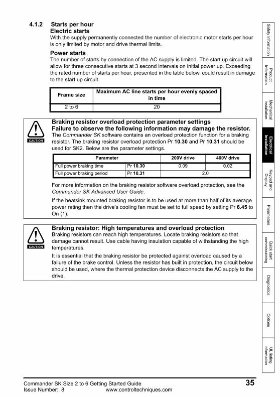
Braking resistor overload protection parameter settingsFailure to observe the following information may damage the resistor.The Commander SK software contains an overload protection function for a braking resistor. The braking resistor overload protection Pr 10.30 and Pr 10.31 should be used for SK2. Below are the parameter settings.
For more information on the braking resistor software overload protection, see the Commander SK Advanced User Guide.If the heatsink mounted braking resistor is to be used at more than half of its average power rating then the drive's cooling fan must be set to full speed by setting Pr 6.45 to On (1).
CAUTION
Parameter 200V drive 400V driveFull power braking time Pr 10.30 0.09 0.02Full power braking period Pr 10.31 2.0
Braking resistor: High temperatures and overload protectionBraking resistors can reach high temperatures. Locate braking resistors so that damage cannot result. Use cable having insulation capable of withstanding the high temperatures.It is essential that the braking resistor be protected against overload caused by a failure of the brake control. Unless the resistor has built in protection, the circuit below should be used, where the thermal protection device disconnects the AC supply to the drive.
CAUTION
Commander SK Size 2 to 6 Getting Started Guide 35Issue Number: 8 www.controltechniques.com
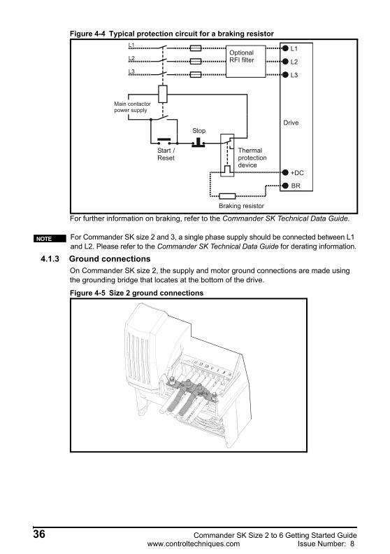
Figure 4-4 Typical protection circuit for a braking resistor
For further information on braking, refer to the Commander SK Technical Data Guide.
4.1.3 Ground connectionsOn Commander SK size 2, the supply and motor ground connections are made using the grounding bridge that locates at the bottom of the drive.
Figure 4-5 Size 2 ground connections
Optional RFI filter
Stop
Start / Reset
Thermal protection device
Braking resistor
Drive
Main contactorpower supply
+DC
BR
For Commander SK size 2 and 3, a single phase supply should be connected between L1 and L2. Please refer to the Commander SK Technical Data Guide for derating information.
NOTE
36 Commander SK Size 2 to 6 Getting Started Guidewww.controltechniques.com Issue Number: 8
Safety Information
Product Inform
ationM
echanical Installation
Electrical Installation
Keypad and D
isplayParam
etersQ
uick start com
missioning
Diagnostics
Options
UL listing
information
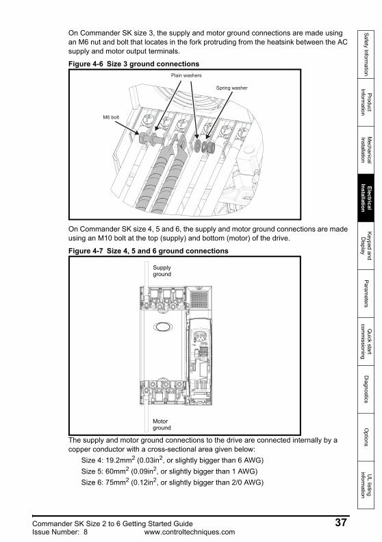
On Commander SK size 3, the supply and motor ground connections are made using an M6 nut and bolt that locates in the fork protruding from the heatsink between the AC supply and motor output terminals.
Figure 4-6 Size 3 ground connections
On Commander SK size 4, 5 and 6, the supply and motor ground connections are made using an M10 bolt at the top (supply) and bottom (motor) of the drive.
Figure 4-7 Size 4, 5 and 6 ground connections
The supply and motor ground connections to the drive are connected internally by a copper conductor with a cross-sectional area given below:
Size 4: 19.2mm2 (0.03in2, or slightly bigger than 6 AWG)Size 5: 60mm2 (0.09in2, or slightly bigger than 1 AWG)Size 6: 75mm2 (0.12in2, or slightly bigger than 2/0 AWG)
Plain washers
Spring washer
M6 bolt
Supplyground
Motorground
Commander SK Size 2 to 6 Getting Started Guide 37Issue Number: 8 www.controltechniques.com
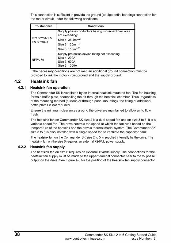
This connection is sufficient to provide the ground (equipotential bonding) connection for the motor circuit under the following conditions:
If the necessary conditions are not met, an additional ground connection must be provided to link the motor circuit ground and the supply ground.
4.2 Heatsink fan 4.2.1 Heatsink fan operation
The Commander SK is ventilated by an internal heatsink mounted fan. The fan housing forms a baffle plate, channelling the air through the heatsink chamber. Thus, regardless of the mounting method (surface or through-panel mounting), the fitting of additional baffle plates is not required.Ensure the minimum clearances around the drive are maintained to allow air to flow freely.The heatsink fan on Commander SK size 2 is a dual speed fan and on size 3 to 6, it is a variable speed fan. The drive controls the speed at which the fan runs based on the temperature of the heatsink and the drive's thermal model system. The Commander SK size 3 to 6 is also installed with a single speed fan to ventilate the capacitor bank.The heatsink fan on the Commander SK size 2 to 5 is supplied internally by the drive. The heatsink fan on the size 6 requires an external +24Vdc power supply.
4.2.2 Heatsink fan supplyThe heatsink fan on size 6 requires an external +24Vdc supply. The connections for the heatsink fan supply must be made to the upper terminal connector near to the W phase output on the drive. See Figure 4-8 for the position of the heatsink fan supply connector.
To standard Conditions
IEC 60204-1 & EN 60204-1
Supply phase conductors having cross-sectional area not exceeding:Size 4: 38.4mm2
Size 5: 120mm2
Size 6: 150mm2
NFPA 79
Supply protection device rating not exceeding:Size 4: 200ASize 5: 600ASize 6: 1000A
38 Commander SK Size 2 to 6 Getting Started Guidewww.controltechniques.com Issue Number: 8
Safety Information
Product Inform
ationM
echanical Installation
Electrical Installation
Keypad and D
isplayParam
etersQ
uick start com
missioning
Diagnostics
Options
UL listing
information
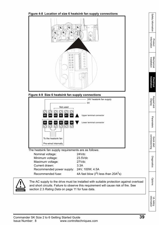
Figure 4-8 Location of size 6 heatsink fan supply connections
Figure 4-9 Size 6 heatsink fan supply connections
The heatsink fan supply requirements are as follows:Nominal voltage: 24VdcMinimum voltage: 23.5VdcMaximum voltage: 27VdcCurrent drawn: 3.3ARecommended power supply: 24V, 100W, 4.5ARecommended fuse: 4A fast blow (I2t less than 20A2s)
55 54 53 52 51 50
65 64 63 62 61 60
To the heatsink fan
Pre-wired internally
Not used
0V24V heatsink fan supply
Upper terminal connector
Lower terminal connector
The AC supply to the drive must be installed with suitable protection against overload and short circuits. Failure to observe this requirement will cause risk of fire. See section 2.3 Rating Data on page 11 for fuse data.WARNING
Commander SK Size 2 to 6 Getting Started Guide 39Issue Number: 8 www.controltechniques.com
4.3 Ground leakage The ground leakage current depends upon the internal EMC filter being installed. The drive is supplied with the filter installed. Instructions on removal of the internal EMC filter are given in section 4.3.1 Internal EMC filter on page 40.
With internal EMC filter installedSize 2 and 3
28mA* AC at 400V, 50Hz30μA DC with 600V DC bus (10MΩ)
Size 4 to 656mA* at 400V, 50Hz18μA DC with 600V DC bus (33MΩ)
*Proportional to the supply voltage and frequency.
With internal EMC filter removed<1mA
4.3.1 Internal EMC filterIt is recommended that the internal EMC filter be kept in place unless there is a specific reason for removing it.
For instructions on removal, refer to Figure 4-10.
The drive must be grounded by a conductor sufficient to carry the prospective fault current in the event of a fault. See also the warning in section 4.3 Ground leakage relating to ground leakage current.WARNING
The above leakage currents are just the leakage currents of the drive with the internal EMC filter connected and do not take into account any leakage currents of the motor or motor cables.
NOTE
In both cases, there is an internal voltage surge protection device connected to ground. Under normal circumstances this carries negligible current.
NOTE
When the internal EMC filter is installed, the leakage current is high. In this case, a permanent fixed ground connection must be provided, or suitable measures taken to prevent a safety hazard occurring if the connection is lost.WARNING
On Commander SK size 3, 4, 5 and 6, when used with ungrounded (IT) supplies, the internal EMC filter must be removed unless additional motor ground fault protection is installed or, in the case of size 3 only, the external EMC filter is also used.WARNING
40 Commander SK Size 2 to 6 Getting Started Guidewww.controltechniques.com Issue Number: 8
Safety Information
Product Inform
ationM
echanical Installation
Electrical Installation
Keypad and D
isplayParam
etersQ
uick start com
missioning
Diagnostics
Options
UL listing
information
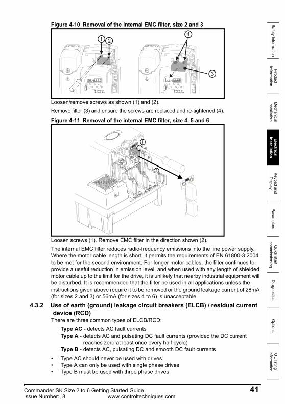
Figure 4-10 Removal of the internal EMC filter, size 2 and 3
Loosen/remove screws as shown (1) and (2).Remove filter (3) and ensure the screws are replaced and re-tightened (4).
Figure 4-11 Removal of the internal EMC filter, size 4, 5 and 6
Loosen screws (1). Remove EMC filter in the direction shown (2).The internal EMC filter reduces radio-frequency emissions into the line power supply. Where the motor cable length is short, it permits the requirements of EN 61800-3:2004 to be met for the second environment. For longer motor cables, the filter continues to provide a useful reduction in emission level, and when used with any length of shielded motor cable up to the limit for the drive, it is unlikely that nearby industrial equipment will be disturbed. It is recommended that the filter be used in all applications unless the instructions given above require it to be removed or the ground leakage current of 28mA (for sizes 2 and 3) or 56mA (for sizes 4 to 6) is unacceptable.
4.3.2 Use of earth (ground) leakage circuit breakers (ELCB) / residual current device (RCD)
There are three common types of ELCB/RCD:Type AC - detects AC fault currentsType A - detects AC and pulsating DC fault currents (provided the DC current
reaches zero at least once every half cycle)Type B - detects AC, pulsating DC and smooth DC fault currents
• Type AC should never be used with drives• Type A can only be used with single phase drives• Type B must be used with three phase drives
1 2
3
4
1
2
Commander SK Size 2 to 6 Getting Started Guide 41Issue Number: 8 www.controltechniques.com
4.3.3 Further EMC precautionsFurther EMC precautions are required if more stringent EMC emission requirements apply:• Operation in the first environment• Conformity to the generic emission standards• Equipment which is sensitive to electrical interference operating nearbyIn this case it is necessary to use:
The optional external EMC filterA shielded motor cable, with the shield clamped to the grounded metal panelA shielded control cable, with the shield clamped to the grounded metal panelFull instructions are given in the Commander SK Technical Data Guide
A full range of external EMC filters is also available for use with Commander SK.
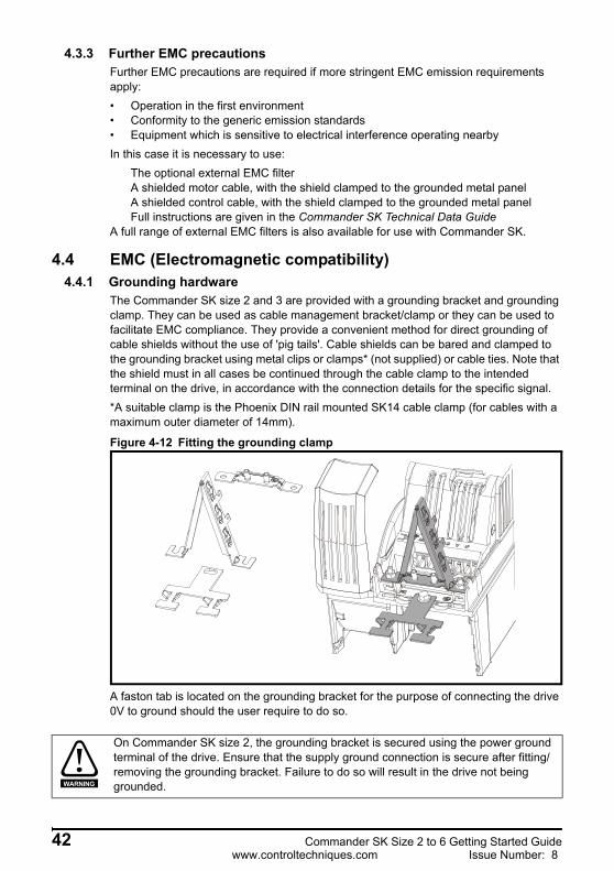
4.4 EMC (Electromagnetic compatibility)4.4.1 Grounding hardware
The Commander SK size 2 and 3 are provided with a grounding bracket and grounding clamp. They can be used as cable management bracket/clamp or they can be used to facilitate EMC compliance. They provide a convenient method for direct grounding of cable shields without the use of 'pig tails'. Cable shields can be bared and clamped to the grounding bracket using metal clips or clamps* (not supplied) or cable ties. Note that the shield must in all cases be continued through the cable clamp to the intended terminal on the drive, in accordance with the connection details for the specific signal.*A suitable clamp is the Phoenix DIN rail mounted SK14 cable clamp (for cables with a maximum outer diameter of 14mm).
Figure 4-12 Fitting the grounding clamp
A faston tab is located on the grounding bracket for the purpose of connecting the drive 0V to ground should the user require to do so.
On Commander SK size 2, the grounding bracket is secured using the power ground terminal of the drive. Ensure that the supply ground connection is secure after fitting/removing the grounding bracket. Failure to do so will result in the drive not being grounded.WARNING
42 Commander SK Size 2 to 6 Getting Started Guidewww.controltechniques.com Issue Number: 8
Safety Information
Product Inform
ationM
echanical Installation
Electrical Installation
Keypad and D
isplayParam
etersQ
uick start com
missioning
Diagnostics
Options
UL listing
information
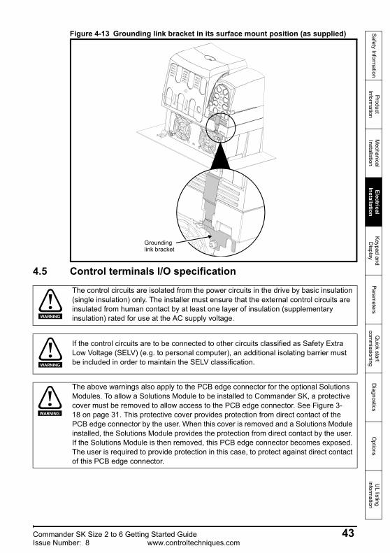
Figure 4-13 Grounding link bracket in its surface mount position (as supplied)
4.5 Control terminals I/O specification
Grounding link bracket
The control circuits are isolated from the power circuits in the drive by basic insulation (single insulation) only. The installer must ensure that the external control circuits are insulated from human contact by at least one layer of insulation (supplementary insulation) rated for use at the AC supply voltage.WARNING
If the control circuits are to be connected to other circuits classified as Safety Extra Low Voltage (SELV) (e.g. to personal computer), an additional isolating barrier must be included in order to maintain the SELV classification.WARNING
The above warnings also apply to the PCB edge connector for the optional Solutions Modules. To allow a Solutions Module to be installed to Commander SK, a protective cover must be removed to allow access to the PCB edge connector. See Figure 3-18 on page 31. This protective cover provides protection from direct contact of the PCB edge connector by the user. When this cover is removed and a Solutions Module installed, the Solutions Module provides the protection from direct contact by the user. If the Solutions Module is then removed, this PCB edge connector becomes exposed. The user is required to provide protection in this case, to protect against direct contact of this PCB edge connector.
WARNING
Commander SK Size 2 to 6 Getting Started Guide 43Issue Number: 8 www.controltechniques.com

User interface terminals can only be considered safe to touch if double insulation is present and the terminals are SELV compliant.
The voltage which is present between 0V and ground / earth is due to capacitive coupling between the power and control circuits in the inverter. The stray capacitance between the power and control circuits results in a high frequency leakage current flowing. The current, which flows is dependent on the level of capacitance present. Note that because of the high frequency content it cannot be measured correctly by a DVM.The size 3 drive has a relatively high capacitance compared to size 2 and the current can cause a painful shock, which is not directly hazardous, but could result in an accident.The voItage present between the 0V terminal and earth / ground may damage external equipment connected to the drive’s 0V terminal. On the Commander SK the serial communications port is not double insulated and thus the serial communications 0V is connected directly to the control 0V therefore equipment connected via serial communications can also be affected. The following precautions should be implemented. This can be easily completed in two ways:1. Connecting the 0V directly to the triangular grounding bracket supplied with the
drive.2. Connecting the 0V directly to earth / ground using the M5 ground connection.
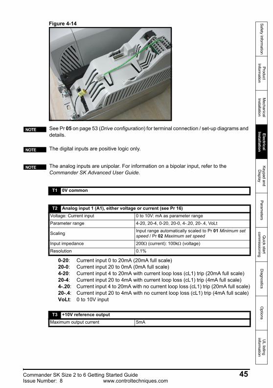
If it is required for the 0V to remain floating with respect to earth, such as when a 4-20mA reference is being used, then this connection can be made using a capacitor of 15nF or higher (600Vdc). However, it should be recognized that there is only single isolation, and the appropriate access protection should be facilitated. The same part is available to order from your drive supplier for the Commander SK if required, the part number is: 9500-0083. It should be connected as shown in Figure 4-14.
Electric shock riskThe voltages present in the following locations can cause severe electric shock and may be lethal:• AC supply cables and connections• DC and brake cables, and connections• Output cables and connections• Many internal parts of the drive, and external option unitsUnless otherwise indicated, control terminals are single insulated and must not be touched.
WARNING
It has come to our attention that not all users are following this advice and that on touching the 0V connection on a size 3 drive an electric shock has been experienced. WARNING
44 Commander SK Size 2 to 6 Getting Started Guidewww.controltechniques.com Issue Number: 8
Safety Information
Product Inform
ationM
echanical Installation
Electrical Installation
Keypad and D
isplayParam
etersQ
uick start com
missioning
Diagnostics
Options
UL listing
information
Figure 4-14
0-20: Current input 0 to 20mA (20mA full scale)20-0: Current input 20 to 0mA (0mA full scale)4-20: Current input 4 to 20mA with current loop loss (cL1) trip (20mA full scale)20-4: Current input 20 to 4mA with current loop loss (cL1) trip (4mA full scale)4-.20: Current input 4 to 20mA with no current loop loss (cL1) trip (20mA full scale)20-.4: Current input 20 to 4mA with no current loop loss (cL1) trip (4mA full scale)VoLt: 0 to 10V input
See Pr 05 on page 53 (Drive configuration) for terminal connection / set-up diagrams and details.
NOTE
The digital inputs are positive logic only.NOTE
The analog inputs are unipolar. For information on a bipolar input, refer to the Commander SK Advanced User Guide.
NOTE
T1 0V common
T2 Analog input 1 (A1), either voltage or current (see Pr 16)Voltage: Current input 0 to 10V: mA as parameter rangeParameter range 4-20, 20-4, 0-20, 20-0, 4-.20, 20-.4, VoLt
Scaling Input range automatically scaled to Pr 01 Minimum set speed / Pr 02 Maximum set speed
Input impedance 200Ω (current): 100kΩ (voltage)Resolution 0.1%
T3 +10V reference outputMaximum output current 5mA
Commander SK Size 2 to 6 Getting Started Guide 45Issue Number: 8 www.controltechniques.com
T4 Analog input 2 (A2), either voltage or digital inputVoltage: Digital input 0 to +10V: 0 to +24V
Scaling (as voltage input) Input range automatically scaled to Pr 01 Minimum set speed / Pr 02 Maximum set speed
Resolution 0.1%Input impedance 100kΩ (voltage): 6k8 (digital input)Normal threshold voltage (as digital input) +10V (positive logic only)
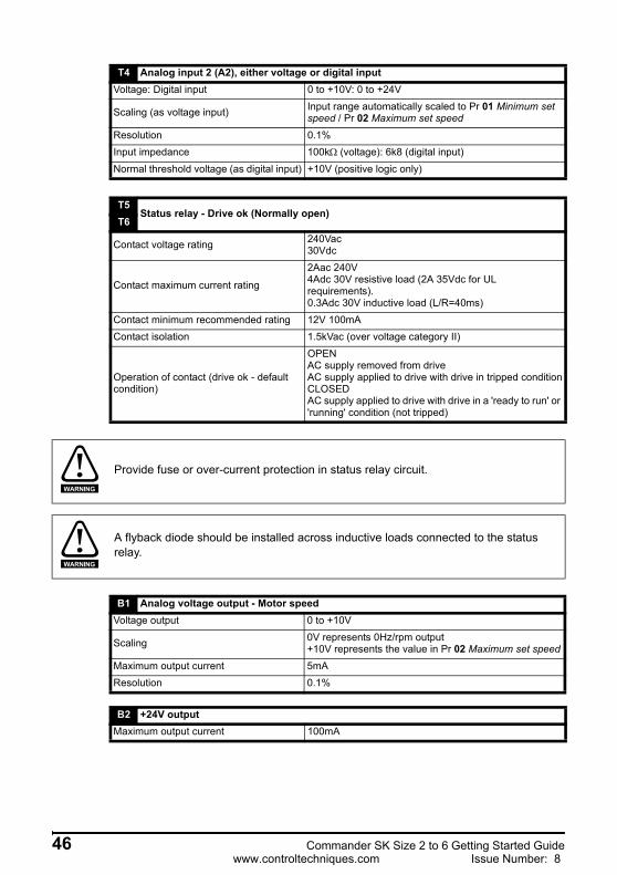
T5Status relay - Drive ok (Normally open)
T6
Contact voltage rating 240Vac30Vdc
Contact maximum current rating
2Aac 240V4Adc 30V resistive load (2A 35Vdc for UL requirements).0.3Adc 30V inductive load (L/R=40ms)
Contact minimum recommended rating 12V 100mAContact isolation 1.5kVac (over voltage category II)
Operation of contact (drive ok - default condition)
OPENAC supply removed from driveAC supply applied to drive with drive in tripped conditionCLOSEDAC supply applied to drive with drive in a 'ready to run' or 'running' condition (not tripped)
Provide fuse or over-current protection in status relay circuit.WARNING
A flyback diode should be installed across inductive loads connected to the status relay.
WARNING
B1 Analog voltage output - Motor speedVoltage output 0 to +10V
Scaling 0V represents 0Hz/rpm output+10V represents the value in Pr 02 Maximum set speed
Maximum output current 5mAResolution 0.1%
B2 +24V outputMaximum output current 100mA
46 Commander SK Size 2 to 6 Getting Started Guidewww.controltechniques.com Issue Number: 8
Safety Information
Product Inform
ationM
echanical Installation
Electrical Installation
Keypad and D
isplayParam
etersQ
uick start com
missioning
Diagnostics
Options
UL listing
information
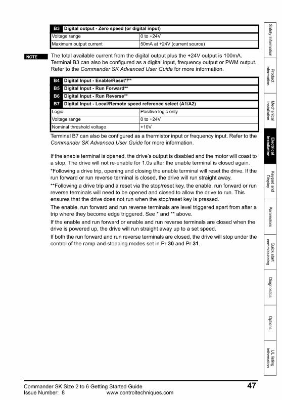
Terminal B7 can also be configured as a thermistor input or frequency input. Refer to the Commander SK Advanced User Guide for more information.
If the enable terminal is opened, the drive’s output is disabled and the motor will coast to a stop. The drive will not re-enable for 1.0s after the enable terminal is closed again.*Following a drive trip, opening and closing the enable terminal will reset the drive. If the run forward or run reverse terminal is closed, the drive will run straight away.**Following a drive trip and a reset via the stop/reset key, the enable, run forward or run reverse terminals will need to be opened and closed to allow the drive to run. This ensures that the drive does not run when the stop/reset key is pressed. The enable, run forward and run reverse terminals are level triggered apart from after a trip where they become edge triggered. See * and ** above.If the enable and run forward or enable and run reverse terminals are closed when the drive is powered up, the drive will run straight away up to a set speed.If both the run forward and run reverse terminals are closed, the drive will stop under the control of the ramp and stopping modes set in Pr 30 and Pr 31.
B3 Digital output - Zero speed (or digital input)Voltage range 0 to +24VMaximum output current 50mA at +24V (current source)
The total available current from the digital output plus the +24V output is 100mA. Terminal B3 can also be configured as a digital input, frequency output or PWM output. Refer to the Commander SK Advanced User Guide for more information.
NOTE
B4 Digital Input - Enable/Reset*/**B5 Digital Input - Run Forward**B6 Digital Input - Run Reverse**B7 Digital Input - Local/Remote speed reference select (A1/A2)
Logic Positive logic onlyVoltage range 0 to +24VNominal threshold voltage +10V
Commander SK Size 2 to 6 Getting Started Guide 47Issue Number: 8 www.controltechniques.com
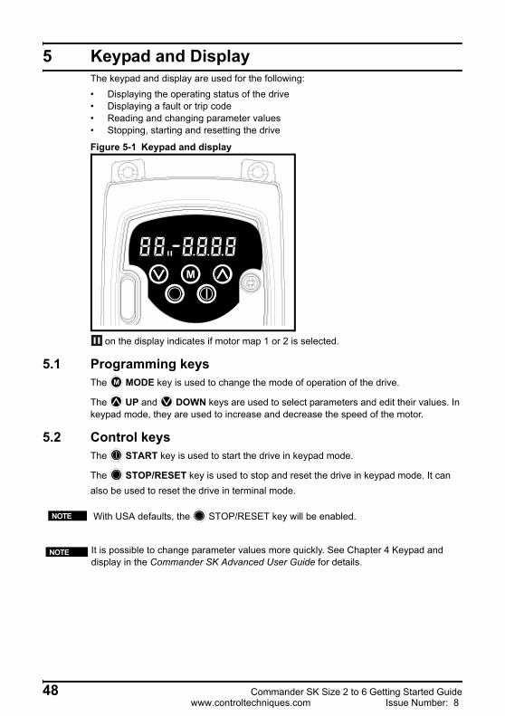
5 Keypad and DisplayThe keypad and display are used for the following:• Displaying the operating status of the drive• Displaying a fault or trip code• Reading and changing parameter values• Stopping, starting and resetting the drive
Figure 5-1 Keypad and display
on the display indicates if motor map 1 or 2 is selected.
5.1 Programming keysThe MODE key is used to change the mode of operation of the drive.
The UP and DOWN keys are used to select parameters and edit their values. In keypad mode, they are used to increase and decrease the speed of the motor.
5.2 Control keysThe START key is used to start the drive in keypad mode.
The STOP/RESET key is used to stop and reset the drive in keypad mode. It can also be used to reset the drive in terminal mode.N
N
M
M
With USA defaults, the STOP/RESET key will be enabled.NOTE
It is possible to change parameter values more quickly. See Chapter 4 Keypad and display in the Commander SK Advanced User Guide for details.
NOTE
48 Commander SK Size 2 to 6 Getting Started Guidewww.controltechniques.com Issue Number: 8
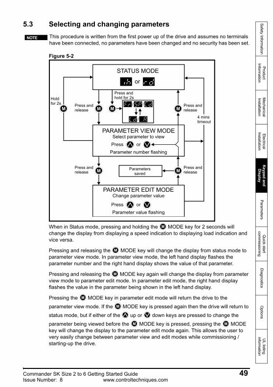
Safety Information
Product Inform
ationM
echanical Installation
Electrical Installation
Keypad and D
isplayParam
etersQ
uick start com
missioning
Diagnostics
Options
UL listing
information
5.3 Selecting and changing parameters
Figure 5-2
When in Status mode, pressing and holding the MODE key for 2 seconds will change the display from displaying a speed indication to displaying load indication and vice versa.
Pressing and releasing the MODE key will change the display from status mode to parameter view mode. In parameter view mode, the left hand display flashes the parameter number and the right hand display shows the value of that parameter.
Pressing and releasing the MODE key again will change the display from parameter view mode to parameter edit mode. In parameter edit mode, the right hand display flashes the value in the parameter being shown in the left hand display.
Pressing the MODE key in parameter edit mode will return the drive to the
parameter view mode. If the MODE key is pressed again then the drive will return to
status mode, but if either of the up or down keys are pressed to change the
parameter being viewed before the MODE key is pressed, pressing the MODE key will change the display to the parameter edit mode again. This allows the user to very easily change between parameter view and edit modes while commissioning / starting-up the drive.
This procedure is written from the first power up of the drive and assumes no terminals have been connected, no parameters have been changed and no security has been set.
NOTE
M
STATUS MODE
or
PARAMETER VIEW MODESelect parameter to view
orPressParameter number flashing
PARAMETER EDIT MODEChange parameter value
orPressParameter value flashing
M M
Press and hold for 2s
M MParameterssaved
Press and releaseM
Holdfor 2s
4 minstimeout
/
/
/ Press and release
Press and release
Press and release
M
M
M
M
M
M M
Commander SK Size 2 to 6 Getting Started Guide 49Issue Number: 8 www.controltechniques.com
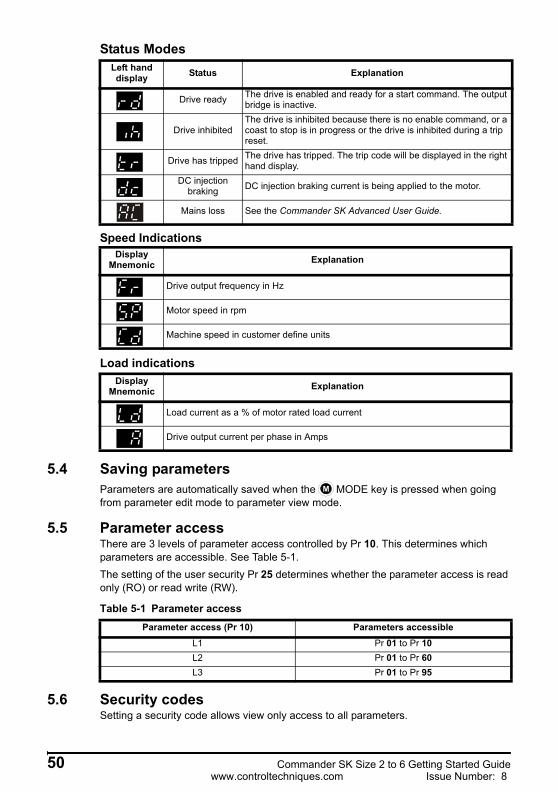
Status Modes
Speed Indications
Load indications
5.4 Saving parametersParameters are automatically saved when the MODE key is pressed when going from parameter edit mode to parameter view mode.
5.5 Parameter accessThere are 3 levels of parameter access controlled by Pr 10. This determines which parameters are accessible. See Table 5-1.The setting of the user security Pr 25 determines whether the parameter access is read only (RO) or read write (RW).
Table 5-1 Parameter access
5.6 Security codesSetting a security code allows view only access to all parameters.
Left hand display Status Explanation
Drive ready The drive is enabled and ready for a start command. The output bridge is inactive.
Drive inhibitedThe drive is inhibited because there is no enable command, or a coast to stop is in progress or the drive is inhibited during a trip reset.
Drive has tripped The drive has tripped. The trip code will be displayed in the right hand display.
DC injection braking DC injection braking current is being applied to the motor.
Mains loss See the Commander SK Advanced User Guide.
Display Mnemonic Explanation
Drive output frequency in Hz
Motor speed in rpm
Machine speed in customer define units
Display Mnemonic Explanation
Load current as a % of motor rated load current
Drive output current per phase in Amps
M
Parameter access (Pr 10) Parameters accessibleL1 Pr 01 to Pr 10L2 Pr 01 to Pr 60L3 Pr 01 to Pr 95
50 Commander SK Size 2 to 6 Getting Started Guidewww.controltechniques.com Issue Number: 8
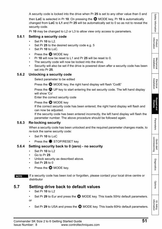
Safety Information
Product Inform
ationM
echanical Installation
Electrical Installation
Keypad and D
isplayParam
etersQ
uick start com
missioning
Diagnostics
Options
UL listing
information
A security code is locked into the drive when Pr 25 is set to any other value than 0 and
then LoC is selected in Pr 10. On pressing the MODE key, Pr 10 is automatically changed from LoC to L1 and Pr 25 will be automatically set to 0 so as not to reveal the security code.Pr 10 may be changed to L2 or L3 to allow view only access to parameters.
5.6.1 Setting a security code• Set Pr 10 to L2.• Set Pr 25 to the desired security code e.g. 5• Set Pr 10 to LoC.
• Press the MODE key• Pr 10 will now be reset to L1 and Pr 25 will be reset to 0.• The security code will now be locked into the drive.• Security will also be set if the drive is powered down after a security code has been
set into Pr 25.5.6.2 Unlocking a security code
Select parameter to be edited
Press the MODE key, the right hand display will flash 'CodE'
Press the UP key to start entering the set security code. The left hand display will show 'Co'Enter the correct security code
Press the MODE keyIf the correct security code has been entered, the right hand display will flash and can now be adjusted.If the security code has been entered incorrectly, the left hand display will flash the parameter number. The above procedure should be followed again.
5.6.3 Re-locking securityWhen a security code has been unlocked and the required parameter changes made, to re-lock the same security code:• Set Pr 10 to LoC
• Press the STOP/RESET key5.6.4 Setting security back to 0 (zero) - no security
• Set Pr 10 to L2• Go to Pr 25• Unlock security as described above.• Set Pr 25 to 0
• Press the MODE key.
5.7 Setting drive back to default values• Set Pr 10 to L2
• Set Pr 29 to Eur and press the MODE key. This loads 50Hz default parameters.or
• Set Pr 29 to USA and press the MODE key. This loads 60Hz default parameters.
M
M
M
M
M
If a security code has been lost or forgotten, please contact your local drive centre or distributor
NOTE
M
M
Commander SK Size 2 to 6 Getting Started Guide 51Issue Number: 8 www.controltechniques.com
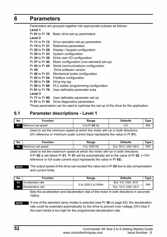
6 ParametersParameters are grouped together into appropriate subsets as follows:Level 1Pr 01 to Pr 10: Basic drive set-up parametersLevel 2Pr 11 to Pr 12: Drive operation set-up parametersPr 15 to Pr 21: Reference parametersPr 22 to Pr 29: Display / keypad configurationPr 30 to Pr 33: System configurationPr 34 to Pr 36: Drive user I/O configurationPr 37 to Pr 42: Motor configuration (non-standard set-up)Pr 43 to Pr 44: Serial communications configurationPr 45: Drive software versionPr 46 to Pr 51: Mechanical brake configurationPr 52 to Pr 54: Fieldbus configurationPr 55 to Pr 58: Drive trip logPr 59 to Pr 60: PLC ladder programming configurationPr 61 to Pr 70: User definable parameter areaLevel 3Pr 71 to Pr 80: User definable parameter set-upPr 81 to Pr 95: Drive diagnostics parametersThese parameters can be used to optimise the set-up of the drive for the application.
6.1 Parameter descriptions - Level 1
Used to set the minimum speed at which the motor will run in both directions. (0V reference or minimum scale current input represents the value in Pr 01).
Used to set the maximum speed at which the motor will run in both directions.If Pr 02 is set below Pr 01, Pr 01 will be automatically set to the value of Pr 02. (+10V reference or full scale current input represents the value in Pr 02).
Sets the acceleration and deceleration rate of the motor in both directions in seconds/100Hz.
No Function Range Defaults Type01 Minimum set speed 0 to Pr 02 Hz 0.0 RW
No Function Range Defaults Type02 Maximum set speed 0 to 1500 Hz Eur: 50.0, USA: 60.0 RW
The output speed of the drive can exceed the value set in Pr 02 due to slip compensation and current limits.
No Function Range Defaults Type03 Acceleration rate
0 to 3200.0 s/100HzEur: 5.0, USA: 33.0
RW04 Deceleration rate Eur: 10.0, USA: 33.0
NOTE
If one of the standard ramp modes is selected (see Pr 30 on page 62), the deceleration rate could be extended automatically by the drive to prevent over voltage (OV) trips if the load inertia is too high for the programmed deceleration rate.
NOTE
52 Commander SK Size 2 to 6 Getting Started Guidewww.controltechniques.com Issue Number: 8
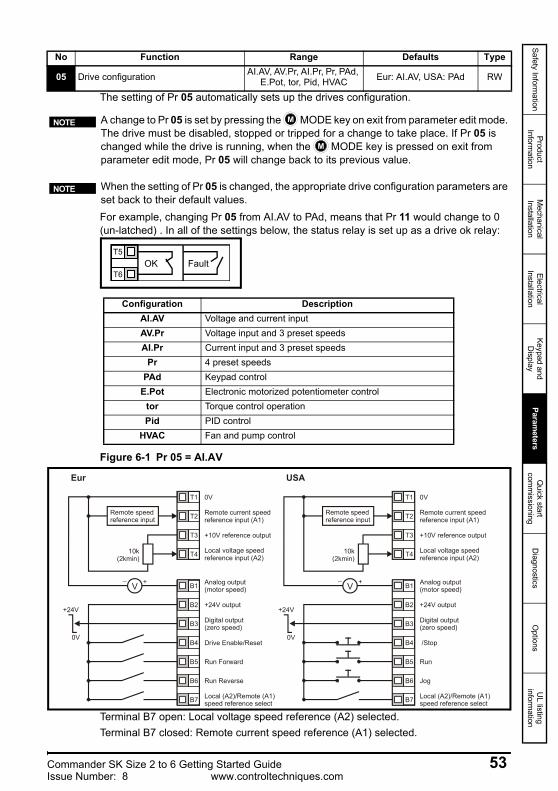
Safety Information
Product Inform
ationM
echanical Installation
Electrical Installation
Keypad and D
isplayParam
etersQ
uick start com
missioning
Diagnostics
Options
UL listing
information
The setting of Pr 05 automatically sets up the drives configuration.
For example, changing Pr 05 from AI.AV to PAd, means that Pr 11 would change to 0 (un-latched) . In all of the settings below, the status relay is set up as a drive ok relay:
Figure 6-1 Pr 05 = AI.AV
Terminal B7 open: Local voltage speed reference (A2) selected.Terminal B7 closed: Remote current speed reference (A1) selected.
No Function Range Defaults Type
05 Drive configuration AI.AV, AV.Pr, AI.Pr, Pr, PAd, E.Pot, tor, Pid, HVAC Eur: AI.AV, USA: PAd RW
A change to Pr 05 is set by pressing the MODE key on exit from parameter edit mode. The drive must be disabled, stopped or tripped for a change to take place. If Pr 05 is changed while the drive is running, when the MODE key is pressed on exit from parameter edit mode, Pr 05 will change back to its previous value.
NOTE M
M
When the setting of Pr 05 is changed, the appropriate drive configuration parameters are set back to their default values.
NOTE
T5
T6OK Fault
Configuration DescriptionAI.AV Voltage and current inputAV.Pr Voltage input and 3 preset speedsAI.Pr Current input and 3 preset speeds
Pr 4 preset speedsPAd Keypad control
E.Pot Electronic motorized potentiometer controltor Torque control operationPid PID control
HVAC Fan and pump control
T1
T2
T3
T4
0V
Remote current speedreference input (A1)
+10V reference output
Local voltage speed reference input (A2)
B1
B2
B3
B4
B5
B6
B7
+24V output
Drive Enable/Reset
Run Forward
Run Reverse
Local (A2)/Remote (A1)speed reference select
Remote speedreference input
V_ +
10k(2kmin)
+24V
0V
Eur
0V
Remote current speedreference input (A1)
+10V reference output
Local voltage speed reference input (A2)
+24V output
/Stop
Run
Jog
Local (A2)/Remote (A1)speed reference select
Remote speedreference input
V_ +
10k(2kmin)
USA
Analog output (motor speed)
Digital output (zero speed)
Analog output (motor speed)
Digital output (zero speed)
+24V
0V
T1
T2
T3
T4
B1
B2
B3
B4
B5
B6
B7
Commander SK Size 2 to 6 Getting Started Guide 53Issue Number: 8 www.controltechniques.com
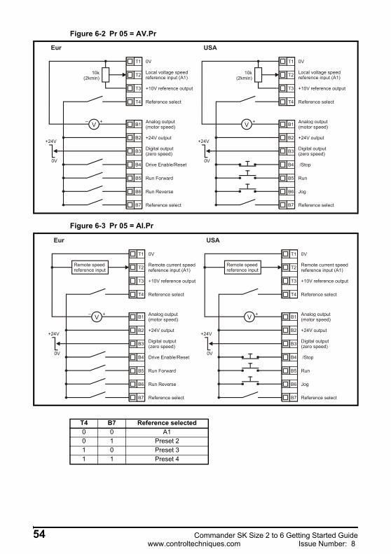
Figure 6-2 Pr 05 = AV.Pr
Figure 6-3 Pr 05 = AI.Pr
0V
Local voltage speedreference input (A1)
+10V reference output
+24V output
Drive Enable/Reset
Run Forward
Run Reverse
V_ +
+24V
0V
Eur USA
Analog output (motor speed)
Digital output (zero speed)
Reference select
Reference select
10k(2kmin)
0V
Local voltage speedreference input (A1)
+10V reference output
+24V output
/Stop
Run
Jog
V_ +
+24V
0V
Analog output (motor speed)
Digital output (zero speed)
Reference select
Reference select
10k(2kmin)
T1
T2
T3
T4
B1
B2
B3
B4
B5
B6
B7
T1
T2
T3
T4
B1
B2
B3
B4
B5
B6
B7
0V
Remote current speedreference input (A1)
+10V reference output
+24V output
Drive Enable/Reset
Run Forward
Run Reverse
Remote speedreference input
V_ +
+24V
0V
Eur USA
Analog output (motor speed)
Digital output (zero speed)
Reference select
Reference select
0V
Remote current speedreference input (A1)
+10V reference output
+24V output
/Stop
Run
Jog
Remote speedreference input
V_ +
+24V
0V
Analog output (motor speed)
Digital output (zero speed)
Reference select
Reference select
T1
T2
T3
T4
B1
B2
B3
B4
B5
B6
B7
T1
T2
T3
T4
B1
B2
B3
B4
B5
B6
B7
T4 B7 Reference selected0 0 A10 1 Preset 21 0 Preset 31 1 Preset 4
54 Commander SK Size 2 to 6 Getting Started Guidewww.controltechniques.com Issue Number: 8
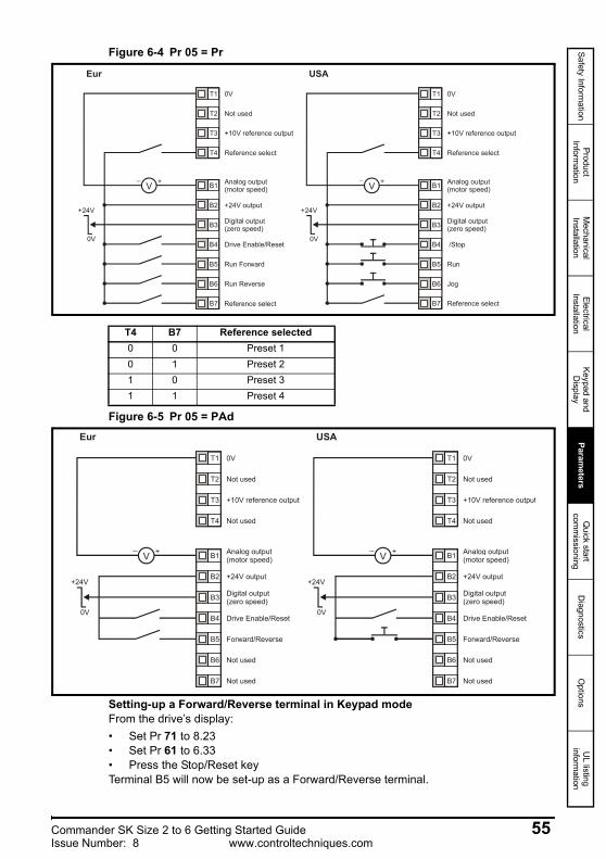
Safety Information
Product Inform
ationM
echanical Installation
Electrical Installation
Keypad and D
isplayParam
etersQ
uick start com
missioning
Diagnostics
Options
UL listing
information
Figure 6-4 Pr 05 = Pr
Figure 6-5 Pr 05 = PAd
Setting-up a Forward/Reverse terminal in Keypad modeFrom the drive’s display:• Set Pr 71 to 8.23• Set Pr 61 to 6.33• Press the Stop/Reset keyTerminal B5 will now be set-up as a Forward/Reverse terminal.
0V
+10V reference output
+24V output
Drive Enable/Reset
Run Forward
Run Reverse
V_ +
+24V
0V
Eur USA
Analog output (motor speed)
Digital output (zero speed)
Reference select
Reference select
0V
+10V reference output
+24V output
/Stop
Run
Jog
V_ +
+24V
0V
Analog output (motor speed)
Digital output (zero speed)
Not used Not used
Reference select
Reference select
T1
T2
T3
T4
B1
B2
B3
B4
B5
B6
B7
T1
T2
T3
T4
B1
B2
B3
B4
B5
B6
B7
T4 B7 Reference selected0 0 Preset 10 1 Preset 21 0 Preset 31 1 Preset 4
0V
+10V reference output
+24V output
Drive Enable/Reset
V_ +
+24V
0V
Eur USA
Analog output (motor speed)
Digital output (zero speed)
Not used
Not used
Not used
Not used
0V
+10V reference output
+24V output
Drive Enable/Reset
V_ +
+24V
0V
Analog output (motor speed)
Digital output (zero speed)
Not used
Not used
Not used
Not used
T1
T2
T3
T4
B1
B2
B3
B4
B5
B6
B7
T1
T2
T3
T4
B1
B2
B3
B4
B5
B6
B7
Forward/Reverse Forward/Reverse
Commander SK Size 2 to 6 Getting Started Guide 55Issue Number: 8 www.controltechniques.com
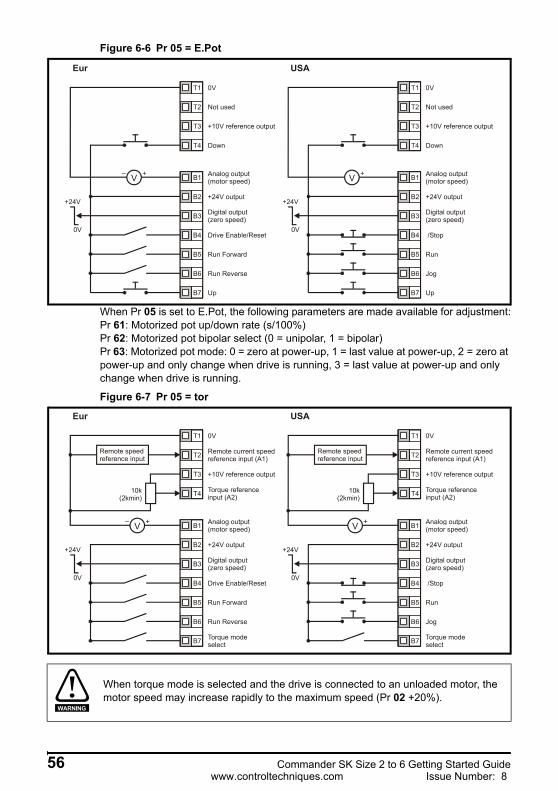
Figure 6-6 Pr 05 = E.Pot
When Pr 05 is set to E.Pot, the following parameters are made available for adjustment:Pr 61: Motorized pot up/down rate (s/100%)Pr 62: Motorized pot bipolar select (0 = unipolar, 1 = bipolar)Pr 63: Motorized pot mode: 0 = zero at power-up, 1 = last value at power-up, 2 = zero at power-up and only change when drive is running, 3 = last value at power-up and only change when drive is running.
Figure 6-7 Pr 05 = tor
0V
+10V reference output
+24V output
Drive Enable/Reset
Run Forward
Run Reverse
V_ +
+24V
0V
Eur USA
Analog output (motor speed)
Digital output (zero speed)
Down
Up
Not used
0V
+10V reference output
+24V output
/Stop
Run
Jog
V_ +
+24V
0V
Analog output (motor speed)
Digital output (zero speed)
Down
Up
Not used
T1
T2
T3
T4
B1
B2
B3
B4
B5
B6
B7
T1
T2
T3
T4
B1
B2
B3
B4
B5
B6
B7
0V
Remote current speedreference input (A1)
+10V reference output
Torque reference input (A2)
+24V output
Drive Enable/Reset
Run Forward
Run Reverse
Torque modeselect
Remote speedreference input
V_ +
10k(2kmin)
+24V
0V
Eur USA
Analog output (motor speed)
Digital output (zero speed)
0V
Remote current speedreference input (A1)
+10V reference output
Torque reference input (A2)
+24V output
/Stop
Run
Jog
Torque modeselect
Remote speedreference input
V_ +
10k(2kmin)
+24V
0V
Analog output (motor speed)
Digital output (zero speed)
T1
T2
T3
T4
B1
B2
B3
B4
B5
B6
B7
T1
T2
T3
T4
B1
B2
B3
B4
B5
B6
B7
When torque mode is selected and the drive is connected to an unloaded motor, the motor speed may increase rapidly to the maximum speed (Pr 02 +20%).
WARNING
56 Commander SK Size 2 to 6 Getting Started Guidewww.controltechniques.com Issue Number: 8
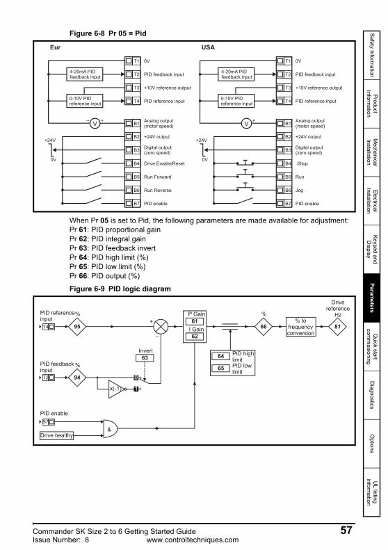
Safety Information
Product Inform
ationM
echanical Installation
Electrical Installation
Keypad and D
isplayParam
etersQ
uick start com
missioning
Diagnostics
Options
UL listing
information
Figure 6-8 Pr 05 = Pid
When Pr 05 is set to Pid, the following parameters are made available for adjustment:Pr 61: PID proportional gainPr 62: PID integral gainPr 63: PID feedback invertPr 64: PID high limit (%)Pr 65: PID low limit (%)Pr 66: PID output (%)
Figure 6-9 PID logic diagram
0V
+10V reference output
+24V output
Drive Enable/Reset
Run Forward
Run Reverse
4-20mA PIDfeedback input
V_ +
+24V
0V
Eur USA
Analog output (motor speed)
Digital output (zero speed)
PID feedback input
PID reference input
PID enable
0-10V PIDreference input
0V
+10V reference output
+24V output
/Stop
Run
Jog
4-20mA PIDfeedback input
V_ +
+24V
0V
Analog output (motor speed)
Digital output (zero speed)
PID reference input
PID enable
0-10V PIDreference input
PID feedback input
T1
T2
T3
T4
B1
B2
B3
B4
B5
B6
B7
T1
T2
T3
T4
B1
B2
B3
B4
B5
B6
B7
95
94
%
T4
T2
x(-1)
63Invert
61P Gain
62I Gain
PID referenceinput
%PID feedbackinput
B7PID enable
&Drive healthy
64 PID highlimit
65 PID low limit
66
%
81
Drivereference
Hz% to
frequencyconversion
+
_
Commander SK Size 2 to 6 Getting Started Guide 57Issue Number: 8 www.controltechniques.com

Figure 6-10 Pr 05 = HVAC terminal configuration
Enter the motor current rating (taken from the motor name plate).
Enter the rated full load speed of the motor (taken from the motor name plate).The motor rated speed is used to calculate the correct slip speed for the motor.
Enter the motor rated voltage (taken from the motor name plate).This is the voltage applied to the motor at base frequency.
No Function Range Defaults Type06 Motor rated current 0 to Drive rated current A Drive rating RW
0V
Remote current speedreference input (A1)
+10V reference output
Not used
+24V output
Drive enable / reset
Run reverse
Referenceselect
Remote speedreference input
V_ +
Eur + USA
Analog output (motor speed)
Digital output (zero speed)
T1
T2
T3
T4
B1
B2
B3
B4
B5
B6
B7
+24V
0V
Autorun
Hand/Off/Autoswitch
H
A
A
Run forward
H: Contacts made in 'hand' position -Keypad controlA: Contacts made in 'auto' position - Remote current speed reference input
Pr 06 Motor rated current must be set correctly to avoid a risk of fire in the event of a motor overload.
No Function Range Defaults Type07 Motor rated speed 0 to 9999 rpm Eur: 1500, USA: 1800 RW
WARNING
A value of zero entered into Pr 07 means slip compensation is disabled. Slip compensation should be disabled when using Commander SK on a high inertia load, e.g. fan.
NOTE
If the full load speed of the motor is above 9999rpm, enter a value of 0 in Pr 07. This will disable slip compensation as values >9999 cannot be entered into this parameter.
NOTE
No Function Range Defaults Type
08 Motor rated voltage 0 to 240V, 0 to 480V, 0 to 575V, 0 to 690V
Eur: 230/400/575/690USA: 230/460/575/690 RW
58 Commander SK Size 2 to 6 Getting Started Guidewww.controltechniques.com Issue Number: 8
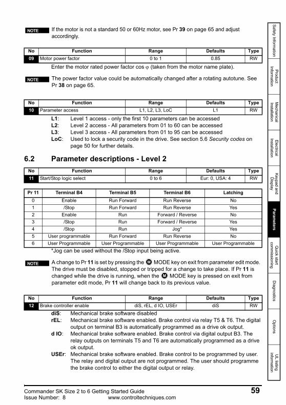
Safety Information
Product Inform
ationM
echanical Installation
Electrical Installation
Keypad and D
isplayParam
etersQ
uick start com
missioning
Diagnostics
Options
UL listing
information
Enter the motor rated power factor cos ϕ (taken from the motor name plate).
L1: Level 1 access - only the first 10 parameters can be accessedL2: Level 2 access - All parameters from 01 to 60 can be accessedL3: Level 3 access - All parameters from 01 to 95 can be accessedLoC: Used to lock a security code in the drive. See section 5.6 Security codes on
page 50 for further details.
6.2 Parameter descriptions - Level 2
*Jog can be used without the /Stop input being active.
diS: Mechanical brake software disabledrEL: Mechanical brake software enabled. Brake control via relay T5 & T6. The digital
output on terminal B3 is automatically programmed as a drive ok output.d IO: Mechanical brake software enabled. Brake control via digital output B3. The
relay outputs on terminals T5 and T6 are automatically programmed as a drive ok output.
USEr: Mechanical brake software enabled. Brake control to be programmed by user. The relay and digital output are not programmed. The user should programme the brake control to either the digital output or relay.
If the motor is not a standard 50 or 60Hz motor, see Pr 39 on page 65 and adjust accordingly.
No Function Range Defaults Type09 Motor power factor 0 to 1 0.85 RW
NOTE
The power factor value could be automatically changed after a rotating autotune. See Pr 38 on page 65.
NOTE
No Function Range Defaults Type10 Parameter access L1, L2, L3, LoC L1 RW
No Function Range Defaults Type11 Start/Stop logic select 0 to 6 Eur: 0, USA: 4 RW
Pr 11 Terminal B4 Terminal B5 Terminal B6 Latching0 Enable Run Forward Run Reverse No1 /Stop Run Forward Run Reverse Yes2 Enable Run Forward / Reverse No3 /Stop Run Forward / Reverse Yes4 /Stop Run Jog* Yes5 User programmable Run Forward Run Reverse No6 User Programmable User Programmable User Programmable User Programmable
A change to Pr 11 is set by pressing the MODE key on exit from parameter edit mode. The drive must be disabled, stopped or tripped for a change to take place. If Pr 11 is changed while the drive is running, when the MODE key is pressed on exit from parameter edit mode, Pr 11 will change back to its previous value.
NOTE M
M
No Function Range Defaults Type12 Brake controller enable diS, rEL, d IO, USEr diS RW
Commander SK Size 2 to 6 Getting Started Guide 59Issue Number: 8 www.controltechniques.com
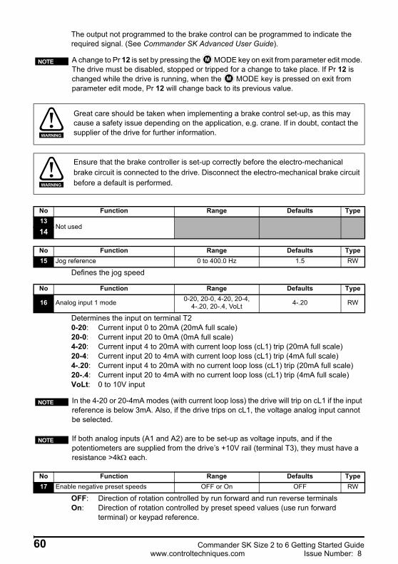
The output not programmed to the brake control can be programmed to indicate the required signal. (See Commander SK Advanced User Guide).
Defines the jog speed
Determines the input on terminal T20-20: Current input 0 to 20mA (20mA full scale)20-0: Current input 20 to 0mA (0mA full scale)4-20: Current input 4 to 20mA with current loop loss (cL1) trip (20mA full scale)20-4: Current input 20 to 4mA with current loop loss (cL1) trip (4mA full scale)4-.20: Current input 4 to 20mA with no current loop loss (cL1) trip (20mA full scale)20-.4: Current input 20 to 4mA with no current loop loss (cL1) trip (4mA full scale)VoLt: 0 to 10V input
OFF: Direction of rotation controlled by run forward and run reverse terminalsOn: Direction of rotation controlled by preset speed values (use run forward
terminal) or keypad reference.
A change to Pr 12 is set by pressing the MODE key on exit from parameter edit mode. The drive must be disabled, stopped or tripped for a change to take place. If Pr 12 is changed while the drive is running, when the MODE key is pressed on exit from parameter edit mode, Pr 12 will change back to its previous value.
NOTE M
M
Great care should be taken when implementing a brake control set-up, as this may cause a safety issue depending on the application, e.g. crane. If in doubt, contact the supplier of the drive for further information.WARNING
Ensure that the brake controller is set-up correctly before the electro-mechanical brake circuit is connected to the drive. Disconnect the electro-mechanical brake circuit before a default is performed.WARNING
No Function Range Defaults Type13
Not used14
No Function Range Defaults Type15 Jog reference 0 to 400.0 Hz 1.5 RW
No Function Range Defaults Type
16 Analog input 1 mode 0-20, 20-0, 4-20, 20-4, 4-.20, 20-.4, VoLt 4-.20 RW
In the 4-20 or 20-4mA modes (with current loop loss) the drive will trip on cL1 if the input reference is below 3mA. Also, if the drive trips on cL1, the voltage analog input cannot be selected.
NOTE
If both analog inputs (A1 and A2) are to be set-up as voltage inputs, and if the potentiometers are supplied from the drive’s +10V rail (terminal T3), they must have a resistance >4kΩ each.
No Function Range Defaults Type17 Enable negative preset speeds OFF or On OFF RW
NOTE
60 Commander SK Size 2 to 6 Getting Started Guidewww.controltechniques.com Issue Number: 8

Safety Information
Product Inform
ationM
echanical Installation
Electrical Installation
Keypad and D
isplayParam
etersQ
uick start com
missioning
Diagnostics
Options
UL listing
information
Defines preset speeds 1 to 4.
Ld: Active current as a % of motor rated active currentA: Drive output current per phase in Amps
Fr: Drive output frequency in HzSP: Motor speed in rpmCd: Machine speed in customer defined units (See Pr 24).
Multiplying factor on motor speed (rpm) to give customer defined units.
Used to set-up a user security code. See section 5.6 Security codes on page 50.
0: keypad reference is zeroLASt: keypad reference is last value selected before the drive was powered downPrS1: keypad reference is copied from preset speed 1
no: no actionrEAd: program the drive with the contents of the SmartStickProg: program the SmartStick with the current drive settingsboot: SmartStick becomes read only. The contents of the SmartStick will be copied to
the drive every time the drive is powered up.
No Function Range Defaults Type18 Preset speed 1
±1500 Hz(Limited by setting of Pr 02
Maximum set speed)0.0 RW
19 Preset speed 220 Preset speed 321 Preset speed 4
No Function Range Defaults Type22 Load display units Ld, A Ld RW
No Function Range Defaults Type23 Speed display units Fr, SP, Cd Fr RW
No Function Range Defaults Type24 Customer defined scaling 0 to 9.999 1.000 RW
No Function Range Defaults Type25 User security code 0 to 999 0 RW
No Function Range Defaults Type26 Not used
No Function Range Defaults Type27 Power up keypad reference 0, LASt, PrS1 0 RW
No Function Range Defaults Type28 Parameter copying no, rEAd, Prog, boot no RW
Before setting boot mode, the current drive settings must be stored in the SmartStick by using Prog mode, otherwise the drive will trip on C.Acc at power-up.Parameter copying is initiated by pressing the MODE key on exit from parameter edit mode after Pr 28 has been set to rEAd, Prog or boot.
NOTE
M
If parameter copying is enabled when no SmartStick is installed in the drive, the drive will trip on C.Acc.
NOTE
Commander SK Size 2 to 6 Getting Started Guide 61Issue Number: 8 www.controltechniques.com
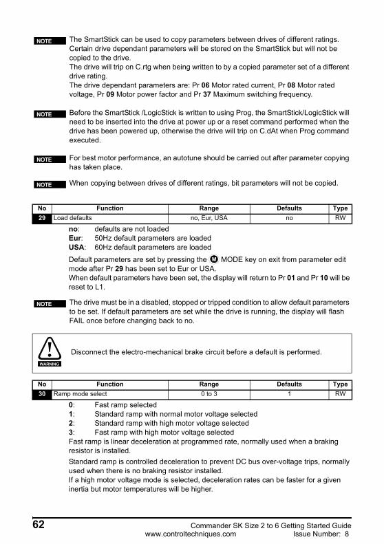
no: defaults are not loadedEur: 50Hz default parameters are loadedUSA: 60Hz default parameters are loaded
Default parameters are set by pressing the MODE key on exit from parameter edit mode after Pr 29 has been set to Eur or USA.When default parameters have been set, the display will return to Pr 01 and Pr 10 will be reset to L1.
0: Fast ramp selected1: Standard ramp with normal motor voltage selected2: Standard ramp with high motor voltage selected3: Fast ramp with high motor voltage selectedFast ramp is linear deceleration at programmed rate, normally used when a braking resistor is installed.Standard ramp is controlled deceleration to prevent DC bus over-voltage trips, normally used when there is no braking resistor installed.If a high motor voltage mode is selected, deceleration rates can be faster for a given inertia but motor temperatures will be higher.
The SmartStick can be used to copy parameters between drives of different ratings. Certain drive dependant parameters will be stored on the SmartStick but will not be copied to the drive.The drive will trip on C.rtg when being written to by a copied parameter set of a different drive rating.The drive dependant parameters are: Pr 06 Motor rated current, Pr 08 Motor rated voltage, Pr 09 Motor power factor and Pr 37 Maximum switching frequency.
NOTE
Before the SmartStick /LogicStick is written to using Prog, the SmartStick/LogicStick will need to be inserted into the drive at power up or a reset command performed when the drive has been powered up, otherwise the drive will trip on C.dAt when Prog command executed.
NOTE
For best motor performance, an autotune should be carried out after parameter copying has taken place.
NOTE
When copying between drives of different ratings, bit parameters will not be copied.
No Function Range Defaults Type29 Load defaults no, Eur, USA no RW
NOTE
M
The drive must be in a disabled, stopped or tripped condition to allow default parameters to be set. If default parameters are set while the drive is running, the display will flash FAIL once before changing back to no.
NOTE
Disconnect the electro-mechanical brake circuit before a default is performed.WARNING
No Function Range Defaults Type30 Ramp mode select 0 to 3 1 RW
62 Commander SK Size 2 to 6 Getting Started Guidewww.controltechniques.com Issue Number: 8

Safety Information
Product Inform
ationM
echanical Installation
Electrical Installation
Keypad and D
isplayParam
etersQ
uick start com
missioning
Diagnostics
Options
UL listing
information
0: Coast to stop selected1: Ramp to stop selected2: Ramp to stop with 1 second DC injection braking3: DC injection braking with detection of zero speed4: Timed DC injection brakingSee the Commander SK Advanced User Guide.
OFF: Fixed linear voltage to frequency ratio (constant torque - standard load)On: Voltage to frequency ratio dependant on load current. This gives a higher motor
efficiency.
0: Disabled1: Detect positive and negative frequencies2: Detect positive frequencies only3: Detect negative frequencies onlyIf the drive is to be configured in fixed boost mode (Pr 41 = Fd or SrE) with catch a spinning motor software enabled, an autotune (see Pr 38 on page 65) must be carried out to measure the motor’s stator resistance beforehand. If a stator resistance is not measured, the drive may trip on OV or OI.AC while trying to catch a spinning motor.
dig: Digital inputth: Motor thermistor input, connect as per diagram belowFr: Frequency input. See Commander SK Advanced User Guide.Fr.hr: High resolution frequency input. See Commander SK Advanced User Guide.
Figure 6-11
Trip resistance: 3kΩReset resistance: 1k8
When standard ramp mode is used, the output frequency can be increased by 20% during deceleration.
NOTE
No Function Range Defaults Type31 Stop mode select 0 to 4 1 RW
No Function Range Defaults Type32 Dynamic V to f select OFF or On OFF RW
No Function Range Defaults Type33 Catch a spinning motor select 0 to 3 0 RW
No Function Range Defaults Type34 Terminal B7 mode select dig, th, Fr, Fr.hr dig RW
0V
Motor thermistorinput
T1
B7
If Pr 34 is set to th so that terminal B7 is used as a motor thermistor, the functionality of terminal B7 as set-up with Pr 05, drive configuration, will be disabled. Analog reference 2 will no longer be selected as the speed reference. Analog reference 1 should be used.
NOTE
When Pr 34 is set to th, the mode button will need to be pressed four times to return the drive display to status mode.
NOTE
Commander SK Size 2 to 6 Getting Started Guide 63Issue Number: 8 www.controltechniques.com

n=0: At zero speedAt.SP: At speedLo.SP: At minimum speedhEAL: Drive okAct: Drive activeALAr: General drive alarmI.Lt: Current limit activeAt.Ld: At 100% loadUSEr: User programmable
Fr: Voltage proportional to motor speedLd: Voltage proportional to motor loadA: Voltage proportional to output currentPor: Voltage proportional to output powerUSEr: User programmable
3: 3kHz6: 6kHz12: 12kHz
See the Commander SK Technical Data Guide for drive derating data.
No Function Range Defaults Type
35 Digital output control (terminal B3) n=0, At.SP, Lo.SP, hEAL, Act, ALAr, I.Lt, At.Ld, USEr n=0 RW
This parameter is automatically changed by the setting of Pr 12. When Pr 12 automatically controls the setting of this parameter, this parameter cannot be changed.
NOTE
A change to Pr 35 is set by pressing the MODE key on exit from parameter edit mode. See the Commander SK Advanced User Guide.
NOTE M
Terminal B3 can also be configured as a digital input, frequency output or PWM output. Refer to the Commander SK Advanced User Guide. for more information.
No Function Range Defaults Type36 Analog output control (terminal B1) Fr, Ld, A, Por, USEr Fr RW
NOTE
A change to Pr 36 is set by pressing the MODE key on exit from parameter edit mode. See the Commander SK Advanced User Guide..
NOTE M
No Function Range Defaults Type37 Maximum switching frequency 3, 6, 12 3 RW
Drive size Voltage rating 3kHz 6kHz 12kHz2 All √ √ √
3
SK320X √ √ √SK3401 & SK3402 √ √ √
SK3403 √ √ √SK350X √ √
4 All √ √5 All √ √6 All √ √
64 Commander SK Size 2 to 6 Getting Started Guidewww.controltechniques.com Issue Number: 8
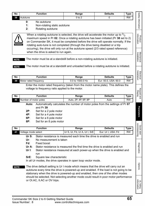
Safety Information
Product Inform
ationM
echanical Installation
Electrical Installation
Keypad and D
isplayParam
etersQ
uick start com
missioning
Diagnostics
Options
UL listing
information
0: No autotune1: Non-rotating static autotune2: Rotating autotune
Enter the motor rated frequency (taken from the motor name plate). This defines the voltage to frequency ratio applied to the motor.
Auto: Automatically calculates the number of motor poles from the settings of Pr 07 and Pr 39
2P: Set for a 2 pole motor4P: Set for a 4 pole motor6P: Set for a 6 pole motor8P: Set for an 8 pole motor
Ur S: Stator resistance is measured each time the drive is enabled and runUr: No measurement is takenFd: Fixed boostUr A: Stator resistance is measured the first time the drive is enabled and runUr I: Stator resistance measured at each power-up when the drive is enabled and
runSrE: Square law characteristicIn all Ur modes, the drive operates in open loop vector mode.
No Function Range Defaults Type38 Autotune 0 to 2 0 RW
When a rotating autotune is selected, the drive will accelerate the motor up to 2/3 maximum speed in Pr 02. Once a rotating autotune has been initiated (Pr 38 set to 2) on Commander SK, it must be completed before the drive will operate normally. If the rotating auto-tune is not completed (through the drive being disabled or a trip occuring), the drive will only run at the autotune speed (2/3 rated speed reference) when the drive is asked to run again.
WARNING
The motor must be at a standstill before a non-rotating autotune is initiated.
The motor must be at a standstill and unloaded before a rotating autotune is initiated.
NOTE
NOTE
No Function Range Defaults Type39 Motor rated frequency 0.0 to 1500.0 Hz Eur: 50.0, USA: 60.0 RW
No Function Range Defaults Type40 Number of motor poles Auto, 2P, 4P, 6P, 8P Auto RW
No Function Range Defaults Type41 Voltage mode select Ur S, Ur, Fd, Ur A, Ur l, SrE Eur: Ur I, USA: Fd RW
The drive default setting is Ur I mode which means that the drive will carry out an autotune every time the drive is powered-up and enabled. If the load is not going to be stationary when the drive is powered-up and enabled, then one of the other modes should be selected. Not selecting another mode could result in poor motor performance or OI.AC, It.AC or OV trips.
NOTE
Commander SK Size 2 to 6 Getting Started Guide 65Issue Number: 8 www.controltechniques.com
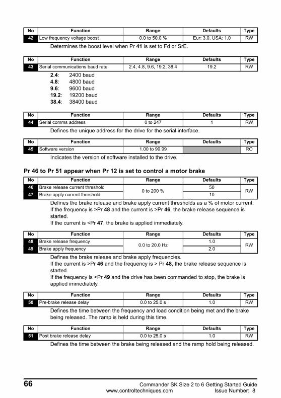
Determines the boost level when Pr 41 is set to Fd or SrE.
2.4: 2400 baud4.8: 4800 baud9.6: 9600 baud19.2: 19200 baud38.4: 38400 baud
Defines the unique address for the drive for the serial interface.
Indicates the version of software installed to the drive.
Pr 46 to Pr 51 appear when Pr 12 is set to control a motor brake
Defines the brake release and brake apply current thresholds as a % of motor current.If the frequency is >Pr 48 and the current is >Pr 46, the brake release sequence is started.If the current is <Pr 47, the brake is applied immediately.
Defines the brake release and brake apply frequencies.If the current is >Pr 46 and the frequency is > Pr 48, the brake release sequence is started.If the frequency is <Pr 49 and the drive has been commanded to stop, the brake is applied immediately.
Defines the time between the frequency and load condition being met and the brake being released. The ramp is held during this time.
Defines the time between the brake being released and the ramp hold being released.
No Function Range Defaults Type42 Low frequency voltage boost 0.0 to 50.0 % Eur: 3.0, USA: 1.0 RW
No Function Range Defaults Type43 Serial communications baud rate 2.4, 4.8, 9.6, 19.2, 38.4 19.2 RW
No Function Range Defaults Type44 Serial comms address 0 to 247 1 RW
No Function Range Defaults Type45 Software version 1.00 to 99.99 RO
No Function Range Defaults Type46 Brake release current threshold
0 to 200 %50
RW47 Brake apply current threshold 10
No Function Range Defaults Type48 Brake release frequency
0.0 to 20.0 Hz1.0
RW49 Brake apply frequency 2.0
No Function Range Defaults Type50 Pre-brake release delay 0.0 to 25.0 s 1.0 RW
No Function Range Defaults Type51 Post brake release delay 0.0 to 25.0 s 1.0 RW
66 Commander SK Size 2 to 6 Getting Started Guidewww.controltechniques.com Issue Number: 8
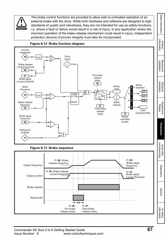
Safety Information
Product Inform
ationM
echanical Installation
Electrical Installation
Keypad and D
isplayParam
etersQ
uick start com
missioning
Diagnostics
Options
UL listing
information
Figure 6-12 Brake function diagram
Figure 6-13 Brake sequence
The brake control functions are provided to allow well co-ordinated operation of an external brake with the drive. While both hardware and software are designed to high standards of quality and robustness, they are not intended for use as safety functions, i.e. where a fault or failure would result in a risk of injury. In any application where the incorrect operation of the brake release mechanism could result in injury, independent protection devices of proven integrity must also be incorporated.
WARNING
Current magnitude
Brake releasecurrent threshold
Brake applycurrent threshold
46
47
+_
Motorfrequency
Brake releasefrequency
Brake applyfrequency
48
49
+_
+_
Referenceenabled
Latch
Driveactive
In Out
Reset
Pre-brake releasedelay
50
Post brake releasedelay
51Brake
release
Brakecontrollerenable
12
T5
T6
B3
Userprogrammable
BrakedisabledRamp
hold
88
85
91
Pr Brake release frequency
48:
Pr : Brake releasecurrent threshold
46
Ramp hold
Pr :Brake applyfrequency
49
Pr :Pre brake
release delay
50 Pr :Post brake release delay
51
Brake release
Output current
Output frequency
Pr :47Brake apply current threshold
Commander SK Size 2 to 6 Getting Started Guide 67Issue Number: 8 www.controltechniques.com
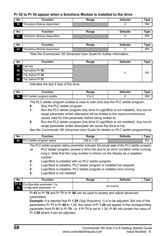
Pr 52 to Pr 54 appear when a Solutions Module is installed to the drive
*See the Commander SK Advanced User Guide for further information.
Indicates the last 4 trips of the drive.
The PLC ladder program enable is used to start and stop the PLC ladder program.0: Stop the PLC ladder program1: Run the PLC ladder program (trip drive if LogicStick is not installed). Any out-of-
range parameter writes attempted will be limited to the maximum/minimum values valid for that parameter before being written to.
2: Run the PLC ladder program (trip drive if LogicStick is not installed). Any out-of-range parameter writes attempted will cause the drive to trip.
See the Commander SK Advanced User Guide for details on PLC ladder programming.
The PLC ladder program status parameter indicates the actual state of the PLC ladder program.-n: PLC ladder program caused a drive trip due to an error condition while running
rung n. Note that the rung number is shown on the display as a negative number.
0: LogicStick is installed with no PLC ladder program1: LogicStick is installed, PLC ladder program is installed but stopped2: LogicStick is installed, PLC ladder program is installed and running3: LogicStick is not installed
Pr 61 to Pr 70 and Pr 71 to Pr 80 can be used to access and adjust advanced parameters.Example: It is desired that Pr 1.29 (Skip frequency 1) is to be adjusted. Set one of the parameters Pr 71 to Pr 80 to 1.29, the value of Pr 1.29 will appear in the corresponding parameter from Pr 61 to Pr 70. I.e. if Pr 71 is set to 1.29, Pr 61 will contain the value of Pr 1.29 where it can be adjusted.
No Function Range Defaults Type52 *Solutions Module dependant 0 RW
No Function Range Defaults Type53 *Solutions Module dependant 0 RW
No Function Range Defaults Type54 *Solutions Module dependant 0 RW
No Function Range Defaults Type55 Last trip
0 RO56 Trip before Pr 5557 Trip before Pr 5658 Trip before Pr 57
No Function Range Defaults Type59 PLC ladder program enable 0 to 2 0 RW
No Function Range Defaults Type60 PLC ladder program status -128 to +127 RO
No Function Range Defaults Type61 to Configurable parameter 1 to
configurable parameter 10 As source70
68 Commander SK Size 2 to 6 Getting Started Guidewww.controltechniques.com Issue Number: 8
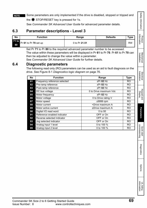
Safety Information
Product Inform
ationM
echanical Installation
Electrical Installation
Keypad and D
isplayParam
etersQ
uick start com
missioning
Diagnostics
Options
UL listing
information
6.3 Parameter descriptions - Level 3
Set Pr 71 to Pr 80 to the required advanced parameter number to be accessed.The value within these parameters will be displayed in Pr 61 to Pr 70. Pr 61 to Pr 70 can then be adjusted to change the value within a parameter.See Commander SK Advanced User Guide for further details.
6.4 Diagnostic parametersThe following read only (RO) parameters can be used as an aid to fault diagnosis on the drive. See Figure 8-1 Diagnostics logic diagram on page 76.
Some parameters are only implemented if the drive is disabled, stopped or tripped and
the STOP/RESET key is pressed for 1s.See Commander SK Advanced User Guide for advanced parameter details.
NOTE
No Function Range Defaults Type71 to
Pr 61 to Pr 70 set up 0 to Pr 21.51 RW80
No Function Range Type81 Frequency reference selected ±Pr 02 Hz RO82 Pre-ramp reference ±Pr 02 Hz RO83 Post-ramp reference ±Pr 02 Hz RO84 DC bus voltage 0 to Drive maximum Vdc RO85 Motor frequency ±Pr 02 Hz RO86 Motor voltage 0 to Drive rating V RO87 Motor speed ±9999 rpm RO88 Motor current +Drive maximum A RO89 Motor active current ±Drive maximum A RO90 Digital I/O read word 0 to 95 RO91 Reference enabled indicator OFF or On RO92 Reverse selected indicator OFF or On RO93 Jog selected indicator OFF or On RO94 Analog input 1 level 0 to 100 % RO95 Analog input 2 level 0 to 100 % RO
Commander SK Size 2 to 6 Getting Started Guide 69Issue Number: 8 www.controltechniques.com
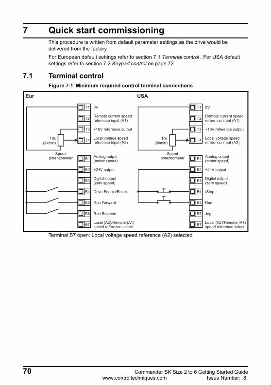
7 Quick start commissioningThis procedure is written from default parameter settings as the drive would be delivered from the factory.For European default settings refer to section 7.1 Terminal control . For USA default settings refer to section 7.2 Keypad control on page 72.
7.1 Terminal controlFigure 7-1 Minimum required control terminal connections
Terminal B7 open: Local voltage speed reference (A2) selected
0V
Remote current speedreference input (A1)
+10V reference output
Local voltage speedreference input (A2)
+24V output
Drive Enable/Reset
Run Forward
Run Reverse
Local (A2)/Remote (A1)speed reference select
10k(2kmin)
Eur USA
Analog output (motor speed)
Digital output (zero speed)
Speedpotentiometer
0V
Remote current speedreference input (A1)
+10V reference output
Local voltage speedreference input (A2)
+24V output
/Stop
Run
Jog
Local (A2)/Remote (A1)speed reference select
10k(2kmin)
Analog output (motor speed)
Digital output (zero speed)
Speedpotentiometer
T1
T2
T3
T4
B1
B2
B3
B4
B5
B6
B7
T1
T2
T3
T4
B1
B2
B3
B4
B5
B6
B7
70 Commander SK Size 2 to 6 Getting Started Guidewww.controltechniques.com Issue Number: 8
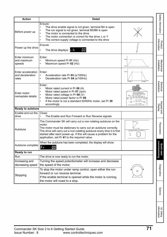
Safety Information
Product Inform
ationM
echanical Installation
Electrical Installation
Keypad and D
isplayParam
etersQ
uick start com
missioning
Diagnostics
Options
UL listing
information
Action Detail
Before power up
Ensure:• The drive enable signal is not given, terminal B4 is open• The run signal is not given, terminal B5/B6 is open• The motor is connected to the drive• The motor connection is correct for the drive Δ or Y• The correct supply voltage is connected to the drive
Power up the driveEnsure:
• The drive displays:
Enter minimum and maximum speeds
Enter:• Minimum speed Pr 01 (Hz)• Maximum speed Pr 02 (Hz)
Enter acceleration and deceleration rates
Enter:• Acceleration rate Pr 03 (s/100Hz)• Deceleration rate Pr 04 (s/100Hz)
Enter motor nameplate details
Enter:• Motor rated current in Pr 06 (A)• Motor rated speed in Pr 07 (rpm)• Motor rated voltage in Pr 08 (V)• Motor rated power factor in Pr 09• If the motor is not a standard 50/60Hz motor, set Pr 39
accordinglyReady to autotuneEnable and run the drive
Close:• The Enable and Run Forward or Run Reverse signals
Autotune
The Commander SK will carry out a non-rotating autotune on the motor.The motor must be stationary to carry out an autotune correctly.The drive will carry out a non-rotating autotune every time it is first started after each power-up. If this will cause a problem for the application, set Pr 41 to the required value.
Autotune completeWhen the autotune has been completed, the display will show:
Ready to runRun The drive is now ready to run the motor.Increasing and decreasing speed
Turning the speed potentiometer will increase and decrease the speed of the motor.
Stopping
To stop the motor under ramp control, open either the run forward or run reverse terminal.If the enable terminal is opened while the motor is running, the motor will coast to a stop.
Pr 02
tPr 01
100Hz
Pr 03t
Pr 04
Mot X XXXXXXXXXNo XXXXXXXXXX kg
IP55 I.cl F C 40 s S1°V Hz min-1 kW cosφ A230400
50 1445 2.20 0.80 8.504.90
CN = 14.5Nm240415
50 1445 2.20 0.76 8.504.90
CN = 14.4NmCTP- VEN 1PHASE 1=0,46A P=110W R.F 32MN I.E
.C 3
4 1(
87)
cos ∅
σLS
RS
Commander SK Size 2 to 6 Getting Started Guide 71Issue Number: 8 www.controltechniques.com
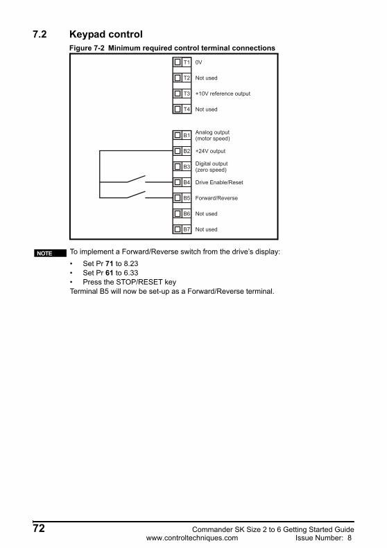
7.2 Keypad controlFigure 7-2 Minimum required control terminal connections
0V
+10V reference output
+24V output
Drive Enable/Reset
Forward/Reverse
Analog output (motor speed)
Digital output (zero speed)
Not used
Not used
Not used
Not used
T1
T2
T3
T4
B1
B2
B3
B4
B5
B6
B7
To implement a Forward/Reverse switch from the drive’s display:• Set Pr 71 to 8.23• Set Pr 61 to 6.33• Press the STOP/RESET keyTerminal B5 will now be set-up as a Forward/Reverse terminal.
NOTE
72 Commander SK Size 2 to 6 Getting Started Guidewww.controltechniques.com Issue Number: 8
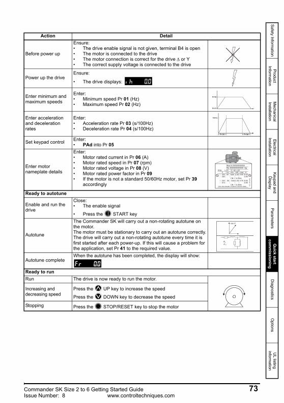
Safety Information
Product Inform
ationM
echanical Installation
Electrical Installation
Keypad and D
isplayParam
etersQ
uick start com
missioning
Diagnostics
Options
UL listing
information
Action Detail
Before power up
Ensure:• The drive enable signal is not given, terminal B4 is open• The motor is connected to the drive• The motor connection is correct for the drive Δ or Y• The correct supply voltage is connected to the drive
Power up the driveEnsure:
• The drive displays:
Enter minimum and maximum speeds
Enter:• Minimum speed Pr 01 (Hz)• Maximum speed Pr 02 (Hz)
Enter acceleration and deceleration rates
Enter:• Acceleration rate Pr 03 (s/100Hz)• Deceleration rate Pr 04 (s/100Hz)
Set keypad control Enter:• PAd into Pr 05
Enter motor nameplate details
Enter:• Motor rated current in Pr 06 (A)• Motor rated speed in Pr 07 (rpm)• Motor rated voltage in Pr 08 (V)• Motor rated power factor in Pr 09• If the motor is not a standard 50/60Hz motor, set Pr 39
accordingly
Ready to autotune
Enable and run the drive
Close:• The enable signal
• Press the START key
Autotune
The Commander SK will carry out a non-rotating autotune on the motor. The motor must be stationary to carry out an autotune correctly.The drive will carry out a non-rotating autotune every time it is first started after each power-up. If this will cause a problem for the application, set Pr 41 to the required value.
Autotune completeWhen the autotune has been completed, the display will show:
Ready to runRun The drive is now ready to run the motor.
Increasing and decreasing speed
Press the UP key to increase the speed
Press the DOWN key to decrease the speed
Stopping Press the STOP/RESET key to stop the motor
Pr 02
tPr 01
100Hz
Pr 03t
Pr 04
Mot X XXXXXXXXXNo XXXXXXXXXX kg
IP55 I.cl F C 40 s S1°V Hz min-1 kW cosφ A230400
50 1445 2.20 0.80 8.504.90
CN = 14.5Nm240415
50 1445 2.20 0.76 8.504.90
CN = 14.4NmCTP- VEN 1PHASE 1=0,46A P=110W R.F 32MN I.E.C
34
1(87
)
cos ∅
σLS
RS
Commander SK Size 2 to 6 Getting Started Guide 73Issue Number: 8 www.controltechniques.com
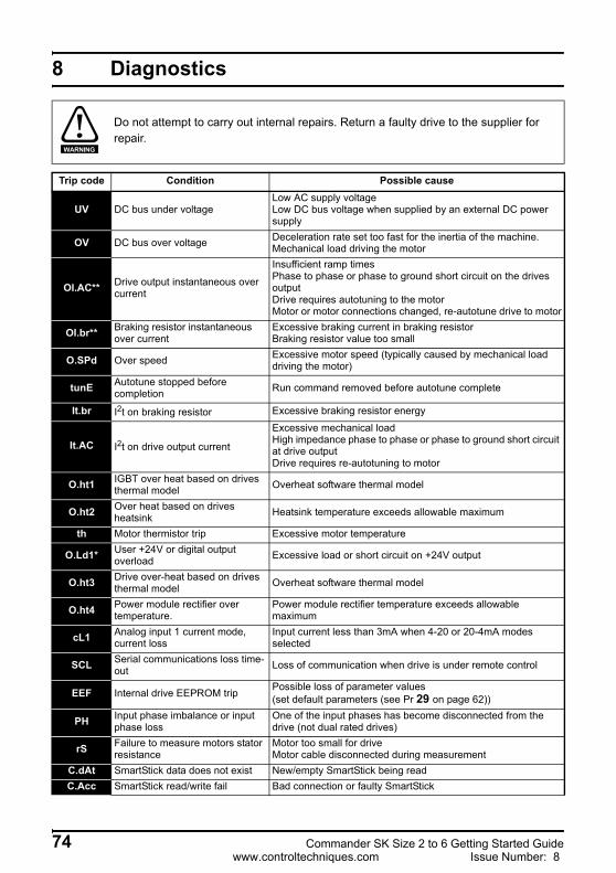
8 Diagnostics
Do not attempt to carry out internal repairs. Return a faulty drive to the supplier for repair.
WARNING
Trip code Condition Possible cause
UV DC bus under voltageLow AC supply voltageLow DC bus voltage when supplied by an external DC power supply
OV DC bus over voltage Deceleration rate set too fast for the inertia of the machine. Mechanical load driving the motor
OI.AC** Drive output instantaneous over current
Insufficient ramp timesPhase to phase or phase to ground short circuit on the drives outputDrive requires autotuning to the motorMotor or motor connections changed, re-autotune drive to motor
OI.br** Braking resistor instantaneous over current
Excessive braking current in braking resistorBraking resistor value too small
O.SPd Over speed Excessive motor speed (typically caused by mechanical load driving the motor)
tunE Autotune stopped before completion Run command removed before autotune complete
It.br I2t on braking resistor Excessive braking resistor energy
It.AC I2t on drive output current
Excessive mechanical loadHigh impedance phase to phase or phase to ground short circuit at drive outputDrive requires re-autotuning to motor
O.ht1 IGBT over heat based on drives thermal model Overheat software thermal model
O.ht2 Over heat based on drives heatsink Heatsink temperature exceeds allowable maximum
th Motor thermistor trip Excessive motor temperature
O.Ld1* User +24V or digital output overload Excessive load or short circuit on +24V output
O.ht3 Drive over-heat based on drives thermal model Overheat software thermal model
O.ht4 Power module rectifier over temperature.
Power module rectifier temperature exceeds allowable maximum
cL1 Analog input 1 current mode, current loss
Input current less than 3mA when 4-20 or 20-4mA modes selected
SCL Serial communications loss time-out Loss of communication when drive is under remote control
EEF Internal drive EEPROM trip Possible loss of parameter values(set default parameters (see Pr 29 on page 62))
PH Input phase imbalance or input phase loss
One of the input phases has become disconnected from the drive (not dual rated drives)
rS Failure to measure motors stator resistance
Motor too small for driveMotor cable disconnected during measurement
C.dAt SmartStick data does not exist New/empty SmartStick being readC.Acc SmartStick read/write fail Bad connection or faulty SmartStick
74 Commander SK Size 2 to 6 Getting Started Guidewww.controltechniques.com Issue Number: 8
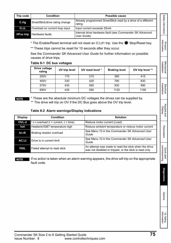
Safety Information
Product Inform
ationM
echanical Installation
Electrical Installation
Keypad and D
isplayParam
etersQ
uick start com
missioning
Diagnostics
Options
UL listing
information
* The Enable/Reset terminal will not reset an O.Ld1 trip. Use the Stop/Reset key.** These trips cannot be reset for 10 seconds after they occur.See the Commander SK Advanced User Guide for further information on possible causes of drive trips.Table 8-1 DC bus voltages
Table 8-2 Alarm warnings/Display indications
C.rtg SmartStick/drive rating change Already programmed SmartStick read by a drive of a different rating
O.cL Overload on current loop input Input current exceeds 25mA
HFxx trip Hardware faults Internal drive hardware fault (see Commander SK Advanced User Guide)
Trip code Condition Possible cause
Drive voltage rating UV trip level UV reset level * Braking level OV trip level **
200V 175 215 390 415400V 330 425 780 830575V 435 590 930 990690V 435 590 1120 1190
* These are the absolute minimum DC voltages the drives can be supplied by.** The drive will trip on OV if the DC Bus goes above the OV trip level.
NOTE
Display Condition SolutionOVL.d I x t overload (I = current, t = time) Reduce motor current (Load)
hot Heatsink/IGBT temperature high Reduce ambient temperature or reduce motor current
br.rS Braking resistor overload See Menu 10 in the Commander SK Advanced User Guide
AC.Lt Drive is in current limit See Menu 10 in the Commander SK Advanced User Guide
FAIL Failed attempt to read stick An attempt was made to read the stick when the drive was not disabled or tripped, or the stick is read only
If no action is taken when an alarm warning appears, the drive will trip on the appropriate fault code.
NOTE
Commander SK Size 2 to 6 Getting Started Guide 75Issue Number: 8 www.controltechniques.com
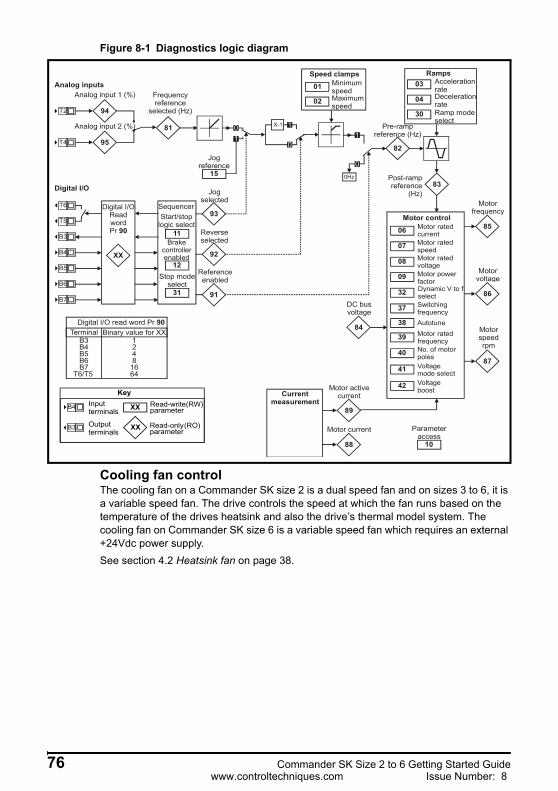
Figure 8-1 Diagnostics logic diagram
Cooling fan controlThe cooling fan on a Commander SK size 2 is a dual speed fan and on sizes 3 to 6, it is a variable speed fan. The drive controls the speed at which the fan runs based on the temperature of the drives heatsink and also the drive’s thermal model system. The cooling fan on Commander SK size 6 is a variable speed fan which requires an external +24Vdc power supply.See section 4.2 Heatsink fan on page 38.
Analog inputs
94
95
81
Analog input 1 (%)
Analog input 2 (%)
Digital I/O
XX
Digital I/OReadwordPr 90
Sequencer
92
93
91
Jogselected
Reverse selected
Referenceenabled
X-1 1
0
01
0
1
0Hz
82
Pre-rampreference (Hz)
84
DC busvoltage
42
41
40
39
38
37
32
09
08
07
06 Motor rated currentMotor rated speedMotor rated voltageMotor power factorDynamic V to fselectSwitching frequencyAutotuneMotor rated frequencyNo. of motorpolesVoltage mode selectVoltage boost
Motor control
03 AccelerationrateDecelerationrate
Ramps
02
01 MinimumspeedMaximumspeed
Speed clamps
83Post-rampreference
(Hz)
85
Motor frequency
86
Motor voltage
87
Motor speedrpm
88
89
Motor current
15
Jogreference
Digital I/O read word Pr 90Terminal Binary value for XX
B3 1B4 2B5 4B6 8B7 16
T6/T5 64
Frequency reference
selected (Hz)04
T2
T4
T6
T5
B3
B4
B5
B6
B7
XX
XX
KeyRead-write (RW) parameter
Read-only (RO)parameter
Inputterminals
Outputterminals
B3
B4
11
12
Start/stoplogic select
Brakecontrollerenabled
31
Stop modeselect
Ramp modeselect
30
Motor activecurrentCurrent
measurement
10
Parameteraccess
76 Commander SK Size 2 to 6 Getting Started Guidewww.controltechniques.com Issue Number: 8
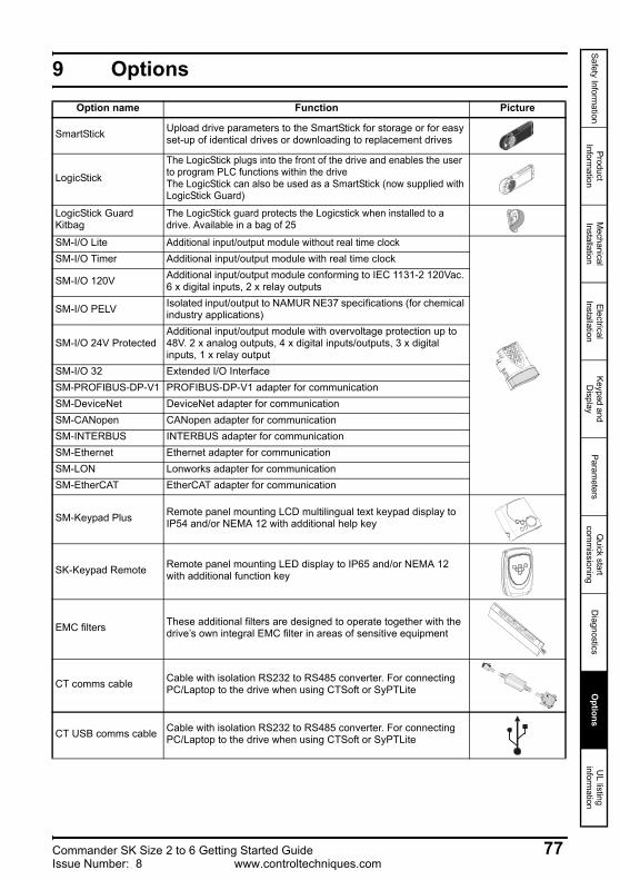
Safety Information
Product Inform
ationM
echanical Installation
Electrical Installation
Keypad and D
isplayParam
etersQ
uick start com
missioning
Diagnostics
Options
UL listing
information
9 OptionsOption name Function Picture
SmartStick Upload drive parameters to the SmartStick for storage or for easy set-up of identical drives or downloading to replacement drives
LogicStick
The LogicStick plugs into the front of the drive and enables the user to program PLC functions within the driveThe LogicStick can also be used as a SmartStick (now supplied with LogicStick Guard)
LogicStick Guard Kitbag
The LogicStick guard protects the Logicstick when installed to a drive. Available in a bag of 25
SM-I/O Lite Additional input/output module without real time clockSM-I/O Timer Additional input/output module with real time clock
SM-I/O 120V Additional input/output module conforming to IEC 1131-2 120Vac. 6 x digital inputs, 2 x relay outputs
SM-I/O PELV Isolated input/output to NAMUR NE37 specifications (for chemical industry applications)
SM-I/O 24V ProtectedAdditional input/output module with overvoltage protection up to 48V. 2 x analog outputs, 4 x digital inputs/outputs, 3 x digital inputs, 1 x relay output
SM-I/O 32 Extended I/O InterfaceSM-PROFIBUS-DP-V1 PROFIBUS-DP-V1 adapter for communicationSM-DeviceNet DeviceNet adapter for communicationSM-CANopen CANopen adapter for communicationSM-INTERBUS INTERBUS adapter for communicationSM-Ethernet Ethernet adapter for communicationSM-LON Lonworks adapter for communicationSM-EtherCAT EtherCAT adapter for communication
SM-Keypad Plus Remote panel mounting LCD multilingual text keypad display to IP54 and/or NEMA 12 with additional help key
SK-Keypad Remote Remote panel mounting LED display to IP65 and/or NEMA 12 with additional function key
EMC filters These additional filters are designed to operate together with the drive’s own integral EMC filter in areas of sensitive equipment
CT comms cable Cable with isolation RS232 to RS485 converter. For connecting PC/Laptop to the drive when using CTSoft or SyPTLite
CT USB comms cable Cable with isolation RS232 to RS485 converter. For connecting PC/Laptop to the drive when using CTSoft or SyPTLite
Commander SK Size 2 to 6 Getting Started Guide 77Issue Number: 8 www.controltechniques.com

Details of all the above options can be found at www.controltechniques.com and on the CD supplied with the drive.
Conduit box Top and bottom metal gland plates to allow the drive to comply with the requirements of UL type 1
AC input line reactors To reduce supply harmonics
CTSoft Software for PC or Laptop which allows the user to commission and store parameter settings
SyPTLite Software for PC or Laptop which allows the user to program PLC functions within the drive
Braking resistor Optional internal braking resistor for Commander SK size 2 (see Commander SK Technical Data Guide for further details).
Option name Function Picture
78 Commander SK Size 2 to 6 Getting Started Guidewww.controltechniques.com Issue Number: 8
Safety Information
Product Inform
ationM
echanical Installation
Electrical Installation
Keypad and D
isplayParam
etersQ
uick start com
missioning
Diagnostics
Options
UL listing
information
10 UL listing informationThe Control Techniques UL file number is E171230. Confirmation of UL listing can be found on the UL website: www.ul.com.
10.1 Common UL informationConformityThe drive conforms to UL listing requirements only when the following are observed:• The drive is installed in a type 1 enclosure, or better, as defined by UL50• The ambient temperature does not exceed 40°C (104°F) when the drive is
operating• The terminal tightening torques specified in section 3.6.1 Terminal sizes and torque
settings on page 32.Motor overload protectionThe drive provides motor overload protection. The default overload protection level is no higher than 150% of full-load current (FLC) of the drive. It is necessary for the motor rated current to be entered into Pr 06 (or Pr 5.07) for the protection to operate correctly. The protection level may be adjusted below 150% if required. The drive also provides motor thermal protection, refer to Pr 4.15, Pr 4.19 and Pr 4.25 in the Commander SK Advanced User Guide. Overspeed protectionThe drive provides overspeed protection. However, it does not provide the level of protection afforded by an independent high integrity overspeed protection device.
10.2 Power dependant UL informationConformityThe drive conforms to UL listing requirements only when the following is observed:
Fuses Size 2 to 3• The correct UL-listed high speed/fast acting fuses (class CC or class J up to 30A
and class J above 30A), e.g. Bussman Limitron KTK series, Gould Amp-Trap ATM series or equivalent, are used in the AC supply. The drive does not comply with UL if MCBs are used in place of fuses.
For further details on fusing, refer to section 2.3 Rating Data on page 11.Size 4 to 6• The UL-listed Ferraz HSJ (High speed J class) fuses are used in the AC supply. The
drive does not comply with UL if any other fuses or MCBs are used in place of those stated.
For further details on fusing, refer to section 2.3 Rating Data on page 11.
Field wiringSize 2 to 4• Class 1 60/75°C (140/167°F) copper wire only is used in the installationSize 5 and 6• Class 1 75°C (167°F) copper wire only is used in the installation
Field wiring connectorsSizes 4 to 6• UL listed wire connectors are used for terminating power circuit field wiring, e.g.
Ilsco TA series
Commander SK Size 2 to 6 Getting Started Guide 79Issue Number: 8 www.controltechniques.com
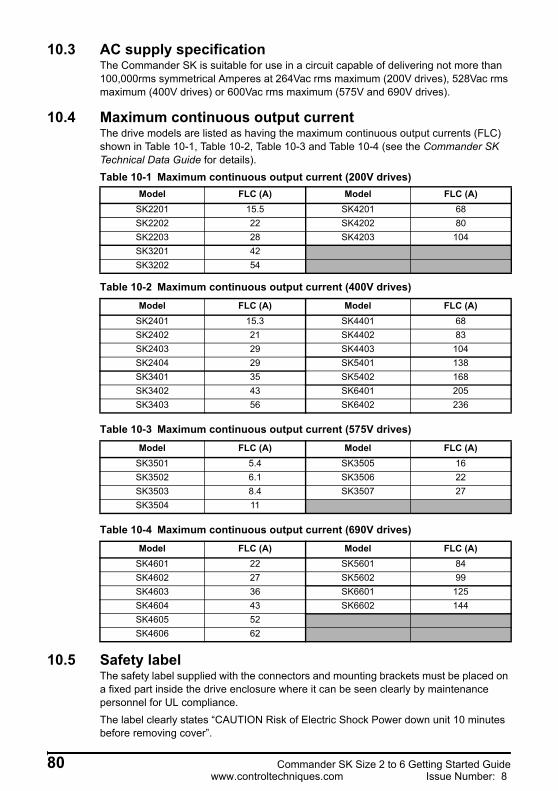
10.3 AC supply specificationThe Commander SK is suitable for use in a circuit capable of delivering not more than 100,000rms symmetrical Amperes at 264Vac rms maximum (200V drives), 528Vac rms maximum (400V drives) or 600Vac rms maximum (575V and 690V drives).
10.4 Maximum continuous output currentThe drive models are listed as having the maximum continuous output currents (FLC) shown in Table 10-1, Table 10-2, Table 10-3 and Table 10-4 (see the Commander SK Technical Data Guide for details).Table 10-1 Maximum continuous output current (200V drives)
Table 10-2 Maximum continuous output current (400V drives)
Table 10-3 Maximum continuous output current (575V drives)
Table 10-4 Maximum continuous output current (690V drives)
10.5 Safety labelThe safety label supplied with the connectors and mounting brackets must be placed on a fixed part inside the drive enclosure where it can be seen clearly by maintenance personnel for UL compliance.The label clearly states “CAUTION Risk of Electric Shock Power down unit 10 minutes before removing cover”.
Model FLC (A) Model FLC (A)SK2201 15.5 SK4201 68SK2202 22 SK4202 80SK2203 28 SK4203 104SK3201 42SK3202 54
Model FLC (A) Model FLC (A)SK2401 15.3 SK4401 68SK2402 21 SK4402 83SK2403 29 SK4403 104SK2404 29 SK5401 138SK3401 35 SK5402 168SK3402 43 SK6401 205SK3403 56 SK6402 236
Model FLC (A) Model FLC (A)SK3501 5.4 SK3505 16SK3502 6.1 SK3506 22SK3503 8.4 SK3507 27SK3504 11
Model FLC (A) Model FLC (A)SK4601 22 SK5601 84SK4602 27 SK5602 99SK4603 36 SK6601 125SK4604 43 SK6602 144SK4605 52SK4606 62
80 Commander SK Size 2 to 6 Getting Started Guidewww.controltechniques.com Issue Number: 8

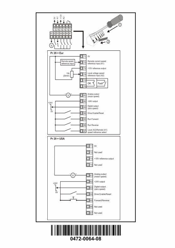
0472-0064-08
T1
T2
T3
T4
0V
Remote current speedreference input (A1)
+10V reference output
Local voltage speed reference input (A2)
B1
B2
B3
B4
B5
B6
B7
+24V output
Drive Enable/Reset
Run Forward
Run Reverse
Local (A2)/Remote (A1)speed reference select
Remote speedreference input
V_ +
10k(2kmin)
+24V
0V
Pr 29 = Eur
Analog output (motor speed)
Digital output (zero speed)
T5
T6OK Fault
Pr 29 = USA
T3 T4 T5 T6T1 T2
B3 B4 B5 B6B1 B2 B7
0V A1 +10V
A2
1
2V
0V
+10V reference output
+24V output
Drive Enable/Reset
V_ +
+24V
0V
Analog output (motor speed)
Digital output (zero speed)
Not used
Not used
Not used
Not used
T1
T2
T3
T4
B1
B2
B3
B4
B5
B6
B7
Forward/Reverse