accelerating 3d printing process using an extended ant
TRANSCRIPT

Accelerating 3D Printing Process Using anExtended Ant Colony Optimization Algorithm
Kai-Yin Fok†∗, Chi-Tsun Cheng†, Nuwan Ganganath‡, Herbert Ho-Ching Iu‡, and Chi K. Tse††Dept. of Electronic and Information Eng., The Hong Kong Polytechnic University, Hung Hom, Hong Kong
‡School Electrical, Electronic and Computer Eng., The University of Western Australia, Crawley, WA, AustraliaEmail: ∗[email protected]
Abstract—Ant colony optimization (ACO) algorithms havebeen widely adopted in solving combinatorial problems, like thetraveling salesman problem (TSP). Nevertheless, with a propertransformation to TSP, ACO is capable of solving undirectedrural postman problems (URPP) as well. In fact, nozzle pathplanning problems in 3D printing can be represented as URPP.Therefore, in this work, ACO is utilized as a URPP solver toaccelerate the printing process in fused deposition modelingapplications. Furthermore, mechanisms which exploit uniqueproperties in 3D models are proposed to further extend the ACOin the above optimization process. These mechanisms are capableof accelerating ACO by adaptively adjusting its number ofiterations on-the-fly. Simulation results using real-life 3D modelsshow that the proposed extensions can accelerate ACO withoutaffecting the quality of its solutions significantly.
Index Terms—Ant colony optimization, Additive manufactur-ing, 3D printing, Undirected rural postman problem
I. INTRODUCTION
Additive manufacturing is the terminology refers to thefabrication of 3D models by depositing materials in a layerby layer manner. A typical example of additive manufacturingis fused deposition modeling (FDM) which is more widelyknown as 3D printing. To print a computer-aided design(CAD) model, the model is first sliced into multiple thin layersusing a slicer software. In each layer, the model is representedusing large volumes of print segments. The segments arethen converted into control codes by the slicer. A 3D printeris then instructed to perform the corresponding machiningmotions according to the control codes. When the nozzletraverses a print segment, its extruder injects filament towardthe reservoir of the nozzle and causes the molten filament to bedeposited to the desired location on a print bed. The printingnozzle traverses to the next print segments and repeats theprocess until all print segments on the current layer have beendeposited. The print bed is then descended and the printingprocess of the next layer proceeds by depositing material ontop of the layers underneath additively.
The build time of a model mainly comprises the timespent on depositing print segments and maneuvering a nozzlebetween segments known as transitions. The time spent ondepositing material is restricted by the specifications of a3D printer, such as its filament flow rate and the rating ofits heating element. However, the time spent on traversingbetween print segments can be shortened by carefully planningthe path of the nozzle. In this work, the routing problem
of the printing nozzle is formulated as an undirected ruralpostman problem (URPP) [1]. Given a set of edges E (i.e.print segments and transitions) and a set of required edgesEr ∈ E (i.e. print segments only), the objective is to find afast path that traverses all Er at least once. URPP is provento be NP-hard if the subgraph induced by the required edgesare not connected [2].
Researches have been carried out to improve the perfor-mance of 3D printing applications in many different aspects.Wang et al. [3] studied the visual quality of printed objects.They proposed an adaptive slicing scheme which is ableto adjust layer thickness according to the structures of 3Dmodels. They showed that the corresponding build time canbe reduced by using their method while a high visual qualitycan still be preserved. Ezair et al. [4] studied the generation ofsupporting structures in 3D printing. In order to minimize theamount of materials used to form the supporting structures,they proposed an algorithm which can select an appropriateorientation according to the model to be built. In [5], Fok etal. proposed a print plan optimizer based on a deterministicmethod by which sub-optimum solutions were obtained with areasonable computational cost. Recently, they formulated thenozzle path planning problem in 3D printing applications intoa URPP [6]. They modified an existing URPP solver whichsuccessfully shorten the build time by eliminating unnecessarymovements of the printing nozzle.
An ant colony optimization (ACO) algorithm is utilized inthis work as a path optimizer for 3D printing applications.ACO is a nature-inspired meta-heuristic that was proposed byDorigo [7] and first used to solve traveling salesmen problems(TSPs). Nowadays, ACO is applied to solve many other com-binatorial optimization problems such as path planning andnetworking problems [8]–[10]. Extensive researches have beenconducted to improve the performance of ACO. Zheng et al.[11] proposed a parameter-adaptive strategy for ACO. In theirwork, control parameters can be adjusted dynamically duringthe optimization process. Mahia et al. [12] utilized a particleswarm optimization (PSO) method to optimize the parametersin ACO according to the quality of solutions generated bythe artificial ants. Skinderowicz [13] proposed several parallelversions of ACO which utilized graphics processing units(GPUs).
In this work, two mechanisms are proposed to extend ACOfor 3D printing applications. The proposed mechanisms ac-
This is the Pre-Published Version.
The following publication Fok, K. Y., Cheng, C. T., Ganganath, N., Iu, H. H. C., & Chi, K. T. (2018, May). Accelerating 3D Printing Process Using an Extended Ant Colony Optimization Algorithm. In 2018 IEEE International Symposium on Circuits and Systems (ISCAS) (pp. 1-5). IEEE is available at https://dx.doi.org/10.1109/ISCAS.2018.8351113
© 2018 IEEE. Personal use of this material is permitted. Permission from IEEE must be obtained for all other uses, in any current or future media, including reprinting/republishing this material for advertising or promotional purposes, creating new collective works, for resale or redistribution to servers or lists, or reuse of any copyrighted component of this work in other works.

celerate ACO by adaptively adjusting its number of iterationson-the-fly according to the unique properties in the givensliced 3D models. The rest of the paper is arranged as follow.Section II provides the problem formulation. The proposedmechanisms are developed based on unique properties foundin 3D printing. Details of the properties and the correspondingmechanisms are elaborated in Section III. Performances ofthe extended ACO were evaluated using computer simula-tions. Settings and discussions regarding the simulations arepresented in Section IV followed by the simulation results.Finally, Section V concludes the whole paper.
II. PROBLEM FORMULATION
In this work, the printing nozzle path planning problem ineach layer of a sliced model is formulated as a URPP. An over-all optimized print plan can later be obtained by connecting theoptimized paths on different layers successively. In a URPP, aconnected and undirected graph is denoted as G = (V,E). Theaim is to find a fast tour, which can visit all the required edgesEr ∈ E. Under the URPP formulation, print segments areregarded as the required edges Er. All vertices correspondingto edges in Er form a vertex set V . The superset E is formedby including other edges that connecting every vertex pair inV . The set of transitions can therefore be denoted as E \ Er.The objective is to find a fast tour which traverses all Er on G.Since the total time required by the printing nozzle to traverseall the print segments in the model is a constant, during theoptimization process, only the cost associated with transitionswill be considered. In this work, a valid solution representsa route traversing all print segments. The fitness value of asolution is denoted as the time required for the printing nozzleto traverse all the associated transitions on a valid solution.
A. Ant Colony OptimizationACO has been widely used to solve TSP, which artificial
ants are used to find routes that traverse all required vertices.Information exchanges among ants are achieved via depositingartificial pheromone on the graph. In [14], it has been demon-strated that ACO is also capable of solving URPP by firsttransforming the problem into TSP. In this work, the printingnozzle path planning problem is first formulated as a URPP,then transformed to TSP, and finally optimized using ACO.
The amount of pheromone deposited on an edge is inverselyproportional to the cost of the intermediate routing solutions.Therefore, at the end of each iteration, a pheromone matrix isupdated based on the solutions generated by the ants. Here, τi,jrepresents the pheromone level on an edge (i, j), where i andj are the two endpoints of that edge. Apart from pheromoneinformation, a heuristic information ηi,j , is also imposed onedge (i, j), which is inversely proportional to the cost ofthat edge. When an ant searches iteratively for a solution,both heuristic and pheromone information are considered.Assuming the kth ant is now at vertex i, the probability for itto choose (i, j) in its next step is expressed as [8]
pki,j(t) =[τi,j(t)]
α[ηi,j ]β∑
l∈Nki
[τi,l(t)]α[ηi,l]β. (1)
Here, Nki is a set of vertices that have valid paths with vertex
i and are not yet visited by the kth ant. The parameters α andβ are for controlling the behavior of the ants. A detail studyon the selection of α and β can be found in [12].
To avoid local optimum points and premature convergences,an operation called evaporation is used in ACO. It reducespheromone concentrations of all edges proportionally at theend of each iteration. Therefore, at the end of the tth iteration,the pheromone level τi,j on the edge (i, j) is updated as
τi,j(t+ 1) = (1− ρ)τi,j(t) +
m∑k=1
∆τki,j(t).
Here, m denotes the number of ants utilized in the ACO.Nevertheless, ∆τki,j(t) represents the amount of pheromonedeposits by the kth ant on edge (i, j) in the tth iteration. Thepheromone evaporation rate is controlled by ρ ∈ (0, 1). Whilethe search process continues iteratively, pheromone on edgesincluded in poor solutions will receive significant evaporationand will be eliminated in long run.
III. PROPOSED METHOD
In this paper, ACO is used to optimize print plans of 3Dmodels by reducing their corresponding total transition lengthsuch that their build times can be shortened. An extended ACOis proposed in this work, specifically for 3D printing applica-tions, which exploits unique properties in typical sliced 3Dmodels. In this section, the properties and the correspondingmechanisms are introduced.
As mentioned before, a CAD model is first decomposedinto many thin layers. In order to print the model with highvisual quality, accuracy, and fidelity, layers have to be thin.As an example, the commercial slicing software in [15] hasits default layer thickness equals 0.1 mm. Thinner layers aresometimes required to build models with finer details. Undersuch conditions, any two adjacent layers of a sliced modelusually share similar structures as the shape of a 3D modelnormally changes gradually. Figs. 1(a) and 1(b) illustrate twoadjacent layers of a model “TortureTestV2” [16].
According to Figs. 1(a) and 1(b), it can be observed thatlocations and orientations of print segments on these twoadjacent layers are quite similar. Shapes in the two layers arehighly comparable except the orientations of some infillinglines. The proposed method utilizes this property, which adja-cent layers usually have similar structures, to extend genericACO for optimizing print plans.
To ease reading, some terminologies used in this work areintroduced as follows. In ACO, ants search iteratively fora fast route for the nozzle to traverse all print segments.The number of iterations to be executed, namely Nite, isa tuning parameter which is defined by the user and itsvalue is normally fixed throughout the whole optimizationprocess. ACO uses a stochastic mechanism to search forimprovements. It is possible that no further improvement canbe found in some of the iterations. For convenience, the termeffective iteration is introduced in this paper to indicate aniteration in which possible improvements can be found. When
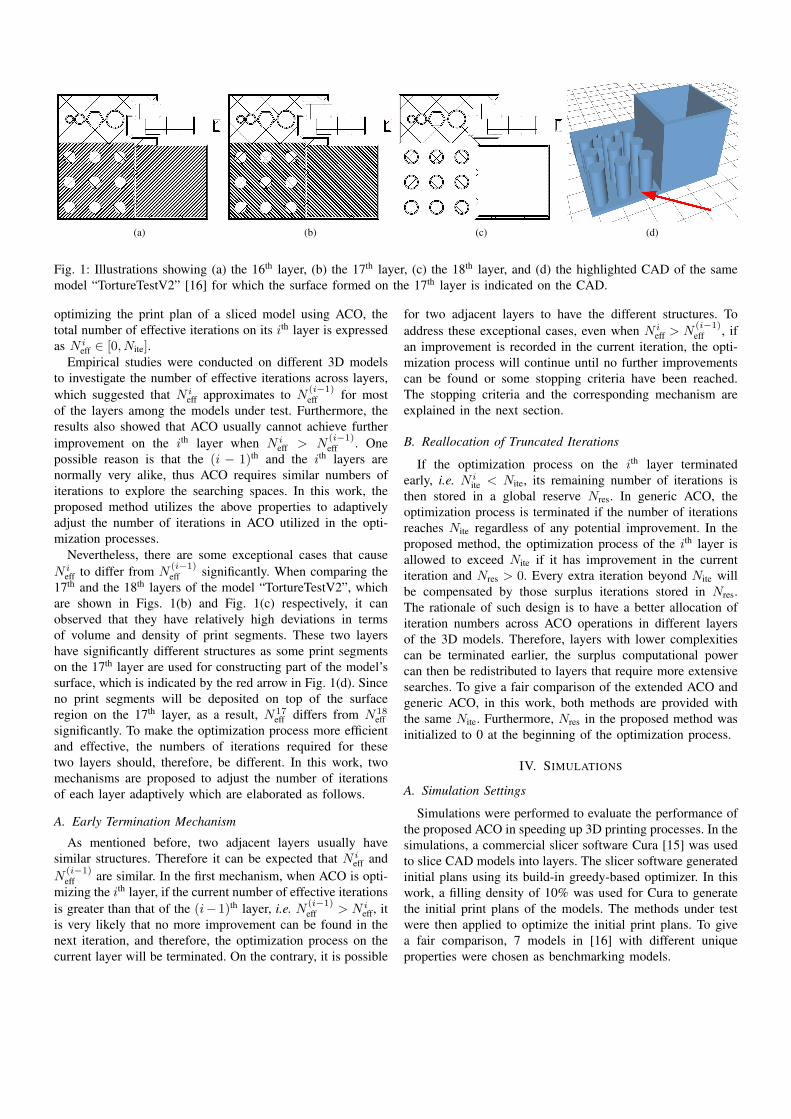
(a) (b) (c) (d)
Fig. 1: Illustrations showing (a) the 16th layer, (b) the 17th layer, (c) the 18th layer, and (d) the highlighted CAD of the samemodel “TortureTestV2” [16] for which the surface formed on the 17th layer is indicated on the CAD.
optimizing the print plan of a sliced model using ACO, thetotal number of effective iterations on its ith layer is expressedas N i
eff ∈ [0, Nite].Empirical studies were conducted on different 3D models
to investigate the number of effective iterations across layers,which suggested that N i
eff approximates to N(i−1)eff for most
of the layers among the models under test. Furthermore, theresults also showed that ACO usually cannot achieve furtherimprovement on the ith layer when N i
eff > N(i−1)eff . One
possible reason is that the (i − 1)th and the ith layers arenormally very alike, thus ACO requires similar numbers ofiterations to explore the searching spaces. In this work, theproposed method utilizes the above properties to adaptivelyadjust the number of iterations in ACO utilized in the opti-mization processes.
Nevertheless, there are some exceptional cases that causeN i
eff to differ from N(i−1)eff significantly. When comparing the
17th and the 18th layers of the model “TortureTestV2”, whichare shown in Figs. 1(b) and Fig. 1(c) respectively, it canobserved that they have relatively high deviations in termsof volume and density of print segments. These two layershave significantly different structures as some print segmentson the 17th layer are used for constructing part of the model’ssurface, which is indicated by the red arrow in Fig. 1(d). Sinceno print segments will be deposited on top of the surfaceregion on the 17th layer, as a result, N17
eff differs from N18eff
significantly. To make the optimization process more efficientand effective, the numbers of iterations required for thesetwo layers should, therefore, be different. In this work, twomechanisms are proposed to adjust the number of iterationsof each layer adaptively which are elaborated as follows.
A. Early Termination Mechanism
As mentioned before, two adjacent layers usually havesimilar structures. Therefore it can be expected that N i
eff andN
(i−1)eff are similar. In the first mechanism, when ACO is opti-
mizing the ith layer, if the current number of effective iterationsis greater than that of the (i− 1)th layer, i.e. N (i−1)
eff > N ieff, it
is very likely that no more improvement can be found in thenext iteration, and therefore, the optimization process on thecurrent layer will be terminated. On the contrary, it is possible
for two adjacent layers to have the different structures. Toaddress these exceptional cases, even when N i
eff > N(i−1)eff , if
an improvement is recorded in the current iteration, the opti-mization process will continue until no further improvementscan be found or some stopping criteria have been reached.The stopping criteria and the corresponding mechanism areexplained in the next section.
B. Reallocation of Truncated Iterations
If the optimization process on the ith layer terminatedearly, i.e. N i
ite < Nite, its remaining number of iterations isthen stored in a global reserve Nres. In generic ACO, theoptimization process is terminated if the number of iterationsreaches Nite regardless of any potential improvement. In theproposed method, the optimization process of the ith layer isallowed to exceed Nite if it has improvement in the currentiteration and Nres > 0. Every extra iteration beyond Nite willbe compensated by those surplus iterations stored in Nres.The rationale of such design is to have a better allocation ofiteration numbers across ACO operations in different layersof the 3D models. Therefore, layers with lower complexitiescan be terminated earlier, the surplus computational powercan then be redistributed to layers that require more extensivesearches. To give a fair comparison of the extended ACO andgeneric ACO, in this work, both methods are provided withthe same Nite. Furthermore, Nres in the proposed method wasinitialized to 0 at the beginning of the optimization process.
IV. SIMULATIONS
A. Simulation Settings
Simulations were performed to evaluate the performance ofthe proposed ACO in speeding up 3D printing processes. In thesimulations, a commercial slicer software Cura [15] was usedto slice CAD models into layers. The slicer software generatedinitial plans using its build-in greedy-based optimizer. In thiswork, a filling density of 10% was used for Cura to generatethe initial print plans of the models. The methods under testwere then applied to optimize the initial print plans. To givea fair comparison, 7 models in [16] with different uniqueproperties were chosen as benchmarking models.

TABLE I: ESTIMATED BUILD TIME (s) OF PRINT PLANS OBTAINED USING DIFFERENT OPTIMIZERS.
Models CuraACO Extended ACO
Mean Max Min SD Mean Max Min SD
3DHackerTest 6551.09 5421.05 5431.65 5412.64 5.16 5418.07 5433.83 5403.67 9.89
ctrlV 3D test 4620.90 4095.21 4115.61 4075.04 14.77 4093.67 4106.78 4076.74 8.15
Debailey x10 5263.32 4725.00 4745.07 4703.78 12.03 4725.65 4759.24 4697.79 22.73
dragon 65 tilted large 3812.74 3083.51 3099.22 3060.56 10.64 3086.78 3099.42 3076.83 7.58
testModel 2537.31 2470.38 2480.27 2461.47 6.48 2479.86 2491.55 2469.29 7.78
TortureTestV2 9951.90 8835.38 8842.75 8829.67 4.32 8835.07 8845.25 8815.06 8.77
UltimakerRobot support 2015 1829.68 1663.11 1670.60 1645.64 7.09 1664.16 1675.37 1655.34 5.05
TABLE II: POST-PROCESSING TIME (s) OF PRINTPLANS OBTAINED USING DIFFERENT OPTIMIZERS.
Models ACO Extended ACO
3DHackerTest 465.73 456.94
ctrlV 3D test 170.73 159.12
Debailey x10 194.91 173.50
dragon 65 tilted large 211.85 199.15
testModel 27.61 24.38
TortureTestV2 221.47 204.51
UltimakerRobot support 2015 122.96 107.74
To evaluate the performance of the proposed method, ageneric ACO with a constant iteration number was alsoincluded in the tests. Both methods were implemented on aGPU-accelerated TSP solver [13] via a URPP to TSP trans-formation. In both optimizers, the values of α, β, and ρ werechosen as 1, 3, and 0.2 respectively as in [13]. Furthermore,Nite = 100 for all the layers. While in the extended ACO, theactual utilized number of iterations in each layer was adjustedby the two proposed mechanisms adaptively on-the-fly.
The optimized plans were evaluated using an open-source3D printing simulator [17]. Each method under test was usedto optimize each model 10 times to obtain the correspondingaverage estimate build time and post-processing time, whichis the time required to further optimize a given print plan. Thesimulations were conducted on a computer with Intel Core i7processors, 16 GB RAM, GeForce GT 750M, Ubuntu 16.04,and CUDA 8.0.61. Simulation results are shown in TABLE Iand TABLE II.
B. Results and Discussion
According to TABLE I, the generic ACO and the extendedACO can always yield solutions with shorter estimated buildtime when compared with those obtained from Cura. Ingeneral, the generic ACO and the extended ACO can onaverage reduce 11.56% and 11.50% of the estimated build timerespectively when comparing to the initial plan generated byCura.
The generic ACO and the extended ACO can reduce theestimated build time of the model “3DHackerTest” by 17.25%and 17.30% respectively at maximum. One possible reason isthat there is a larger number of print segments and irregular
shapes in such model when comparing with the others. There-fore, there are more rooms for ACO to optimize the print plan.Furthermore, the generic ACO and the extended ACO can bothdeliver similar performances on reducing the estimated buildtime of all the 7 models.
According to TABLE II, the extended ACO required shorterpost-processing time when compared with the generic ACO.The proposed method required on average 8.20% less timethan that of the generic ACO. Nevertheless, the proposedmethod can at maximum save 12.38% of post-processing timecomparing to the generic ACO in optimizing the model “Ul-timakerRobot support 2015”. One possible reason is that thestructure of such model is quite uniform across its layers, suchthat, the proposed method was capable to adjust the number ofiterations effectively without degrading its solution quality. Onthe other hand, such improvement gap was reduced to 1.87%for model “3DHackerTest”. As mentioned before, such modelis populated with irregular shapes. The proposed method canstill adaptively reallocate iterations across layers even when thestructures of adjacent layers are having significant deviationsby adopting the mechanism mentioned in Section III.
V. CONCLUSION
In this paper, an extended version of ACO for accelerating3D printing applications is presented. By exploiting the uniqueproperties between adjacent layers in sliced CAD models,the proposed method can adaptively adjust the number ofiterations in ACO on-the-fly. Computer simulations were con-ducted to evaluate its performances. Simulation results showthat the proposed method can significantly accelerate both theoptimization and printing processes without compromising thequality of solutions.
ACKNOWLEDGMENT
This work is supported by the Department of Electronicand Information Engineering, the Hong Kong PolytechnicUniversity (Projects RU9D and G-YBXK).
REFERENCES
[1] C. Orloff, “A fundamental problem in vehicle routing,” Networks, vol. 4,no. 1, pp. 35–64, 1974.
[2] J. K. Lenstra and A. Kan, “On general routing problems,” Networks,vol. 6, no. 3, pp. 273–280, 1976.
[3] W. Wang, H. Chao, J. Tong, Z. Yang, X. Tong, H. Li, X. Liu, and L. Liu,“Saliency-preserving slicing optimization for effective 3D printing,” inComputer Graphics Forum, vol. 34, no. 6. Wiley Online Library, 2015,pp. 148–160.
[4] B. Ezair, F. Massarwi, and G. Elber, “Orientation analysis of 3D objectstoward minimal support volume in 3D-printing,” Computers & Graphics,vol. 51, pp. 117–124, 2015.
[5] K.-Y. Fok, C.-T. Cheng, C. K. Tse, and N. Ganganath, “A relaxationscheme for TSP-based 3D printing path optimizer,” in InternationalConference on Cyber-Enabled Distributed Computing and KnowledgeDiscovery (CyberC 2016), October 2016, pp. 382–385.
[6] K.-Y. Fok, C.-T. Cheng, and C. K. Tse, “A refinement process for nozzlepath planning in 3D printing,” in 2017 IEEE International Symposiumon Circuits and Systems (ISCAS 2017), May 2017, pp. 1–4.
[7] M. Dorigo and G. Di Caro, “Ant colony optimization: a new meta-heuristic,” in Proceedings of the 1999 Congress on Evolutionary Com-putation (CEC99), vol. 2. IEEE, 1999, pp. 1470–1477.
[8] M. Dorigo, M. Birattari, and T. Stutzle, “Ant colony optimization,” IEEEcomputational intelligence magazine, vol. 1, no. 4, pp. 28–39, 2006.
[9] N. Ganganath and C.-T. Cheng, “A 2-dimensional ACO-based pathplanner for off-line robot path planning,” in International Conferenceon Cyber-Enabled Distributed Computing and Knowledge Discovery(CyberC 2013). IEEE, 2013, pp. 302–307.
[10] N. Ganganath, C.-T. Cheng, and C. K. Tse, “An ACO-based off-line pathplanner for nonholonomic mobile robots,” in 2014 IEEE InternationalSymposium on Circuits and Systems (ISCAS 2014). IEEE, 2014, pp.1038–1041.
[11] F. Zheng, A. Zecchin, J. Newman, H. Maier, and G. Dandy, “An adaptiveconvergence-trajectory controlled ant colony optimization algorithmwith application to water distribution system design problems,” IEEETransactions on Evolutionary Computation, March 2017.
[12] M. Mahi, O. K. Baykan, and H. Kodaz, “A new hybrid method basedon particle swarm optimization, ant colony optimization and 3-optalgorithms for traveling salesman problem,” Applied Soft Computing,vol. 30, pp. 484–490, 2015.
[13] R. Skinderowicz, “The GPU-based parallel ant colony system,” Journalof Parallel and Distributed Computing, vol. 98, pp. 48–60, 2016.
[14] M.-L. Perez-Delgado, “Solving an arc-routing problem using artificialants with a graph transformation,” Advances in Practical Applicationsof Agents and Multiagent Systems, pp. 241–246, 2010.
[15] Ultimaker, “Cura 3D printing slicing software,” (Accessed: 2017-02-20).[Online]. Available: https://ultimaker.com/en/products/cura-software
[16] Ultimaker, “GitHub - Ultimaker/CuraEngine,” (Accessed: 2017-02-22).[Online]. Available: https://github.com/Ultimaker/CuraEngine
[17] K.-Y. Fok, “GCodeAnalysor-1.0 by kyfok - Thin-giverse,” (Accessed: 2016-11-9). [Online]. Available:http://www.thingiverse.com/thing:1870254