acceleration sensor-based first resonance … · acceleration sensor-based first resonance...
TRANSCRIPT

Acceleration Sensor-based First ResonanceVibration Suppression of a Double-clampedPiezoelectric BeamZhi-cheng QiuSchool of Mechanical and Automotive Engineering, South China University of Technology, Guangzhou 510641,PR ChinaState Key Laboratory of Robotics, Shenyang Institute of Automation, Chinese Academy of Sciences, Shenyang110016, PR China
Fan-kong MengSchool of Mechanical and Automotive Engineering, South China University of Technology, Guangzhou 510641,PR China
Jian-da Han and Jin-guo LiuState Key Laboratory of Robotics, Shenyang Institute of Automation, Chinese Academy of Sciences, Shenyang110016, PR China
(Received 13 November 2013; accepted 12 March 2014)
This paper investigates resonance vibration suppression under persistent excitation near the first structural reso-nant frequency of a clamped-clamped (doubly-clamped) piezoelectric flexible beam. In this study, an accelerationsensor is used to measure the resonant vibration. Firstly, the finite element method (FEM) is utilized to derivethe dynamics model of the system, and modal analysis is carried out. Secondly, an acceleration feedback-basedproportional-integral control algorithm and variable structure control algorithms are designed, and a numericalsimulation is performed. Finally, a doubly-clamped piezoelectric flexible beam experimental setup is constructed.Experiments are conducted on resonant vibration suppression using the designed control algorithms. The numer-ical simulation and experimental results demonstrate that the resonant vibration can be suppressed by using thedesigned control methods, and the improved variable structure control method shows better control performancein suppressing the resonant vibration.
1. INTRODUCTION
Flexible beam structures are characterized by light weight,low structural damping, and low modal frequencies, and theyare one of the main structure types used in the engineering fieldand aerospace structures.1 Vibrations are easily caused whenflexible beams are subjected to heavy loads or affected by avariety of unexpected external factors in the course of theirwork. Furthermore, these vibrations will last for a long time.If the vibrations are not suppressed effectively, the prolongedvibrations will reduce the working accuracy and working lifeof large and complex structures, such as space crafts and spacerobot manipulators. Moreover, if the structure is excited at itsresonance frequencies, it will be seriously damaged.2 There-fore, active vibration control of flexible structures is an impor-tant concern.
During the past few decades, a considerable amount of studyin the area of active vibration control of flexible structures hasbeen conducted by many researchers. In their investigations,piezoelectric materials (such as PZT, PVDF) are widely usedin active vibration control for flexible structures. They provideinexpensive, reliable, and non-intrusive means of actuating andsensing vibrations in flexible structures.4 Wang, et al.,5 con-ducted a study on the vibration control of smart piezoelectriccomposite plates; they investigated the effect of the stretching-
bending coupling of the piezoelectric sensor and actuator pairson the system stability of smart composite plates. The classi-cal negative velocity feedback control method was adopted forthe active vibration control analysis of smart composite plateswith bonded distributed piezoelectric sensors and actuators intheir study. Sabatini, et al.,6 studied active damping strategiesand relevant devices that could be used to reduce the structuralvibrations of a space manipulator with flexible links during itsin orbit operations. They proposed an optimized adaptive vi-bration control via piezoelectric devices. Carlos, et al.,7 con-ducted an experimental study into the control of a cantileverbeam, which had a PZT patch bonded to it as an actuator anda collocated PVDF patch which was used as the sensor. Theirexperimental results demonstrated the effectiveness of the ac-tive vibration control method. Direct output feedback-basedactive vibration control has been implemented on a smart can-tilever beam at its resonant frequency using PZT sensors andactuators by Parameswaran, et al.,8 They compared the perfor-mance of the conventional PC-based control and a dedicatedreal-time control at resonance, and their experimental resultsdemonstrated that the implementation of real-time control pro-vides a much more controlled response of the system with anexcellent transient response, as well as a highly reliable steadystate response.
International Journal of Acoustics and Vibration, Vol. 21, No. 1, 2016 (pp. 11–23) http://dx.doi.org/10.20855/ijav.2016.21.1391 11

Z. Qiu, et al.: ACCELERATION SENSOR-BASED FIRST RESONANCE VIBRATION SUPPRESSION OF A DOUBLE-CLAMPED PIEZOELECTRIC. . .
What’s more, the acceleration sensor-based control strat-egy is an effective control method used in vibration suppres-sion.9–11 Its best feature is that acceleration is used as the feed-back signal, which can be directly measured by accelerom-eters. In addition, acceleration is easier to measure thanstrain, displacement, or velocity.9, 12 Considerable works havebeen done using the acceleration sensor-based feedback con-trol strategy, showing that acceleration feedback control is ef-fective and robust in vibration measurement and active con-trol.12–17
Mahmoodi, et al.,9 used an active vibration control methodcalled modified acceleration feedback for vibration control ofplate structures as an extension of modified positive positionfeedback. PZT patches were utilized to suppress the vibra-tion of the plate, and the method was successfully verified ona test plate in the laboratory. Preumont, et al.,12 proposed alocal control scheme using acceleration feedback and a col-located proof-mass actuator for active damping of beam-likestructures. They conducted experimental investigations of vi-bration suppression under resonant excitations. Gatti, et al.,13
conducted a theoretical and experimental study of the activevibration control of a simply supported beam using a piezo-electric patch actuator and a physically collocated accelerome-ter. Shin, et al.,14 proposed an active vibration control methodof clamped-clamped beams using acceleration feedback con-trollers with a non-collocated sensor and a moment pair ac-tuator configuration. Qiu, et al.,15, 16 presented an accelera-tion sensor-based active vibration control for a cantilever beamand a cantilever plate with bonded piezoelectric patches. Thephenomenon of phase hysteresis and time delay were consid-ered in their work. The PD control method, a nonlinear con-trol method and acceleration signal-based sliding mode con-trol algorithm were utilized to suppress vibration. Chatterjee17
presented a theoretical basis of time-delayed acceleration feed-back control of linear and nonlinear vibrations of mechanicaloscillators.
In this paper, active vibration control of a doubly-clampedflexible beam with bonded discrete PZT actuators and mountedaccelerometer is investigated. The FEM method is utilizedto model the system, and the acceleration feedback-basedproportional-integral controller and the acceleration feedback-based variable structure controller are designed. Both theo-retical and experimental studies were undertaken to verify thepresented methods.
The original contributions of this paper are detailed as fol-lows: (a) The model of a piezoelectric clamped-clamped beamwith an accelerometer is obtained by FEM. The FEM modelis used for simulations of acceleration feedback control algo-rithms. (b) Acceleration sensor-based proportional and inte-gral control and variable structure control are designed. (c)Simulations and experiments are conducted to validate the ef-fectiveness of the designed controllers in suppressing the reso-nant vibration of the clamped-clamped beam under persistentexcitation.
This article is organized as follows: In Section 2, the dy-namic model of a doubly-clamped piezoelectric beam bondedwith piezoelectric actuators and an accelerometer is derived byusing the finite element method. In Section 3, the accelerationfeedback-based proportional-integral control algorithm and theacceleration feedback based variable structure control methodare proposed, and a numerical simulation is carried out. In
(a) The x− z plane
(b) The x− y plane
Figure 1. Schematic diagram of a doubly-clamped piezoelectric flexible beam.
Section 4, a doubly-clamped piezoelectric flexible beam ex-perimental system is constructed. Experiments are conductedby using the proposed control algorithms. Finally, the conclu-sion is drawn in Section 5.
2. SYSTEM MODELLING
In this section, a mathematical model is derived for adoubly-clamped piezoelectric beam structure equipped withan acceleration sensor and PZT actuators. The finite elementmethod is used to build the dynamics model. The four-noderectangle plate element is utilized. The state-space representa-tion form of the dynamics model is obtained, including accel-eration sensing and piezoelectric driving. Modal analyses areperformed.
2.1. The Doubly-clamped PiezoelectricFlexible Beam
The doubly-clamped piezoelectric flexible beam is schemat-ically depicted in Fig. 1. The flexible beam is bonded with PZTpatches and an accelerometer. Eight PZT patches are bondedon both surfaces of the flexible beam. The patches are dividedinto two groups, and are used as the excited actuator and con-trol actuator. Each group is composed of four piezoelectricpatches, symmetrically bonded on both surfaces close to bothclamped sides. Either group can be used as a one-channel ac-tuator by parallel connection. The left group is used as the ac-tuator to excite the vibration of the beam, and the right groupis used to suppress the vibration of the beam.
As shown in Fig. 1, the accelerometer is located in the in-termediate position of the flexible beam, used to detect the vi-bration of the beam. The length, width, and thickness of theflexible beam structure are lb = 600 mm, wb = 120 mm,and tb = 2 mm, respectively. Those of the PZT patches arelp = 50 mm, wp = 15 mm, and tp = 1 mm, respectively.The diameter and height of the accelerometer are da = 18 mmand ha = 22 mm, respectively. The location of the piezoelec-
12 International Journal of Acoustics and Vibration, Vol. 21, No. 1, 2016

Z. Qiu, et al.: ACCELERATION SENSOR-BASED FIRST RESONANCE VIBRATION SUPPRESSION OF A DOUBLE-CLAMPED PIEZOELECTRIC. . .
Figure 2. Four-node rectangle plate element.
tric actuators and the accelerometer are shown in Fig. 1, wherexp1 = xp2 = 50 mm, yp1 = yp2 = 15 mm, and xa = 300 mm.
2.2. The Element Dynamics EquationThe beam is discretized by using the four-node rectangle
plate element, as shown in Fig. 2. There are three degrees offreedom at each node of the four-node rectangle plate element,described as w, θx, and θy , respectively. The element nodaldisplacement vector can be expressed as
de =[w1 θx1 θy1 w2 θx2 θy2w3 θx3 θy3 w4 θx4 θy4]
T .(1)
The transverse displacement of any point in the element canbe expressed as18
w(x, y) = Nde; (2)
where N ∈ R1×12 is the displacement shape function.The element strain matrix can be expressed using the ele-
ment nodal displacement vector18, 19
ε = zBde; (3)
where B is a matrix representing the relationship between theelement strain matrix and element nodal displacement vector,and z is the variable in the thickness direction.
The dynamics equation of the four-node rectangle plate ele-ment can be written as20
mebd
e + kebd
e = feext; (4)
where meb is the element mass matrix, ke
b is the element stiff-ness matrix, de is the element nodal acceleration vector, de isthe element nodal displacement vector, and feext is the elementexternal force vector.
In Eq. (4), meb =
∫Vb
ρbNTNdV , ke
b =∫Vb
z2BTDbBdV , in
which ρb represents the material densities of the flexible beam,Vb is the element volumes of the rectangle plate element, Db
is the elastic modulus matrix of the rectangle plate element, zrepresents the variable in the thickness direction, and its rangeis [−tb/2 tb/2].
In this investigation, the piezoelectric element is regarded asan ordinary rectangle plate element, so the piezoelectric ele-ment mass matrix me
p =∫Vp
ρpNTNdV , and the piezoelectric
element stiffness matrix is kep =
∫Vp
z2BTDpBdV , in which
ρp denotes the densities of the piezoelectric material, Vp isthe element volumes of the piezoelectric element, Dp is theelastic modulus matrix of the piezoelectric material, z repre-sent the variable in the thickness direction, and its range is[−tp/2 tp/2].
As shown in Fig. 1, PZT patches are used as actuators toexcite or suppress the vibration of the doubly-clamped piezo-electric beam. When a PZT patch is applied to a voltage onlyin the thickness direction, the stress matrix is21
σ = −eTEz; (5)
where σ represents the stress matrix in the piezoelectric actua-tor caused by the electric field, e is the piezoelectric stress con-stant vector, and Ez is the strength of the electric field withinthe piezoelectric actuator.
When the input voltage of the piezoelectric actuator is Va,the strength of the electric field within the piezoelectric actua-tor is22
Ez =Vata
; (6)
where ta is the thickness of the piezoelectric actuator.Substituting Eq. (6) into Eq. (5), the stress matrix in the
piezoelectric actuator is obtained as
σ = −eT Vata. (7)
The driving force of PZT actuators demands that the stresswithin the piezoelectric element is uniformly distributed alongthe thickness direction of the piezoelectric patches. The torquegenerated by the stress is
Ma =
ta+tb/2∫tb/2
σzdz = −ta+tb/2∫tb/2
eTEzdz = zaeTVa; (8)
where Ma is the torque caused by the PZT actuator, and za =(tb+ta)/2 denotes the distance the centreline of the PZT patchto the centreline of the beam.
When a voltage is applied, the work done by the PZT actua-tor is
Fead
e =
∫ ∫ [θx θy θxy
]Madxdy
=
∫Sa
BT zaeTVad
edS = fectrl · Vade; (9)
where Fea is the equivalent nodal load generated by the PZT
actuator, fectrl is the piezoelectric element driving force coef-ficient vector, θxy is the torsional angle corresponding to boththe x- and y- axes, and fectrl =
∫ ∫BT zae
T dxdy.
2.3. State-space Form of the System ModelThe element meshing and numbering of nodes and elements
for the doubly-clamped beam is shown in Fig. 3. The numberin parentheses indicates the element number, and the numbersnear the element node indicate the node numbers. There are24 elements along the length direction and 8 elements along
International Journal of Acoustics and Vibration, Vol. 21, No. 1, 2016 13

Z. Qiu, et al.: ACCELERATION SENSOR-BASED FIRST RESONANCE VIBRATION SUPPRESSION OF A DOUBLE-CLAMPED PIEZOELECTRIC. . .
Figure 3. Meshing and numbering of the elements and nodes for the doubly-clamped piezoelectric beam.
the width direction, so the flexible beam is divided into 192elements and the number of nodes is 225. The length of theelement is 25 mm, and the width of the element is 15 mm. Eachof the PZT patches is divided into two parts in the x direction,and one part in the y direction. After applying the boundarycondition to the beam, the number of the free nodes of thebeam is 207.
The accelerometer is mounted in the intermediate positionof the flexible beam, i.e. the node in the middle position of thebeam structure numbered 113 is regarded as the observationnode of acceleration output. When the finite element method isused to model the dynamics model of the flexible beam system,the effect of the accelerometer on the structural characteristicsshould be considered. Here, the effect of the mounted acceler-ation sensor on the overall stiffness of the structure is ignored;while the mass of the accelerometer cannot be neglected. Itsmass is evenly assigned to the four adjacent elements, so theelement numbers are 92, 93, 100, and 101.
After assembling the element mass matrix, the element stiff-ness matrix and the exciting force coefficient vector of thepiezoelectric element, one can obtain the global mass ma-trix, global stiffness matrix and global control force coeffi-cient vector. The boundary conditions of the flexible beamare two clamped sides. Therefore, the corresponding rowsand columns should be deleted in the global mass and stiffnessmatrices, and in the global exciting and control force vectors.Considering the Rayleigh damping effect, the dynamics equa-tion of the piezoelectric flexible beam structure can be writtenas
Md(t) + Cd(t) + Kd(t) = Fa · Va(t) + Fc · Vc(t); (10)
where M ∈ R3m×3m and K ∈ R3m×3m are the globalmass matrix and global stiffness matrix, respectively; C =αM + βK is the damping matrix, in which α and β areRayleigh damping constants respectively; d(t) ∈ R3m×1,d(t) ∈ R3m×1, and d(t) ∈ R3m×1 are the global nodal ac-celeration vector, the global nodal velocity vector, and globalnodal displacement vector, respectively; Fa ∈ R3m×1 andFc ∈ R3m×1 are the global active force vector used to excitethe vibration of the flexible beam and the global control forcevector that suppresses the vibration of the beam, respectively;
Va(t) is the excitation voltage applied on the vibration excita-tion piezoelectric actuators; Vc(t) is the control voltage appliedon the vibration suppression piezoelectric actuators; and m isthe total number of nodes, where m = 207 after applying theboundary conditions.
The output vibration signal measured by the accelerationsensor is12
ya(t) = Td(t); (11)
where ya(t) is the measured output of the acceleration sensor;T ∈ R1×3m is the acceleration output matrix corresponding tothe observation position; d(t) is the global nodal accelerationvector; and m is the total number of the nodes.
For the convenience of numerical simulation,Eqs. (10) and (11) should be converted into a state-spaceform. By using a modal transformation d = Φg, thedynamics equations of the system can be written as23
Mg(t) + Cg(t) + Kg(t) = Fa · Va(t) + Fc · Vc(t); (12)
andya(t) = TΦg(t); (13)
where Φ is the modal matrix; g is the modal coordinate vector,M = ΦTMΦ is the generalized mass matrix; C = ΦTCΦ isthe generalized damping matrix; K = ΦTKΦ is the general-ized stiffness matrix; Fa is the generalized vibration excitationforce vector; and Fc is the generalized vibration control forcevector.
The state-space representation of Eqs. (12) and (13) is ex-pressed as{
X(t) = AX(t) + BaVa(t) + BcVc(t)ya(t) = CX(t) + DaVa(t) + DcVc(t)
; (14)
where X = [g(t) g(t)]T is the state vector; A =[0 I
−M−1
K −M−1
C
]is the system matrix, Ba =
[0
M−1
ΦT Fa
]is the vibration excitation force matrix; Bc =
[0
M−1
ΦT Fc
]is
the vibration control force matrix; C = −TΦ [M−1
K M−1
C ]
is the acceleration output matrix; and Da = TΦM−1
ΦTFa
and Dc = TΦM−1
ΦTFc are direct transfer coefficients.
14 International Journal of Acoustics and Vibration, Vol. 21, No. 1, 2016

Z. Qiu, et al.: ACCELERATION SENSOR-BASED FIRST RESONANCE VIBRATION SUPPRESSION OF A DOUBLE-CLAMPED PIEZOELECTRIC. . .
Table 1. The modal frequencies of the first four modes of the doubly-clampedbeam.
Order ANSYS software FEM model Relative error(Hz) (Hz)
1 21.453 21.8914 2.04%2 67.212 66.7915 -0.65%3 81.231 81.3994 0.21%4 116.33 116.6680 0.32%
(a) The first mode
(b) The second mode
Figure 4. The first four vibration modes of the doubly-clamped beam obtainedby employing ANSYS software.
2.4. Modal Analysis of the System
The geometrical size of the beam, the PZT patch, andthe accelerometer can be seen in section 2.1. The flexi-ble beam is made of epoxy resin. Young’s modulus, Pois-son’s ratio, and the mass density of the beam structure areEb = 34.64 Gpa, νb = 0.33 and ρb = 1865 Kg/m3, respec-tively. Young’s modulus, Poisson’s ratio, and the mass den-sity of the PZT patches are Ep = 63 Gpa, νp = 0.33, andρp = 7650 Kg/m3, respectively, and the piezoelectric strainconstant is d31 = 166×10−12. The mass of the accelerometeris 38 g, and Young’s modulus, Poisson’s ratio, and the massdensity are Eb = 210 Gpa, νb = 0.3 and ρb = 7850 Kg/m3,respectively.
The model of the doubly-clamped beam system can be ob-tained by using the finite element modelling method, and onecan also get modal frequencies and modal shapes of the sys-tem by using ANSYS software. When ANSYS software isemployed to carry out modal analyses, the SHELL63 elementis used to generate mesh of the beam, and the SOLID45 ele-ment is used to generate mesh of the PZT patches and the ac-celerometer. The modal frequencies of the flexible beam sys-tem are listed in Table 1, calculated by using the FEM methodand ANSYS, respectively. The relative errors between the twomethods are less than 3%. Comparison of the results demon-strates the correctness of the model built by using the FEM.Figures 4 (a) and (b) illustrate the mode shapes of the first twomodes obtained by ANSYS.
3. CONTROL ALGORITHM ANDNUMERICAL SIMULATION
3.1. Acceleration Feedback-basedProportional-Integral Control
In order to suppress the vibration under resonant excita-tion of a doubly-clamped beam effectively, active control al-gorithms need to be designed. During this investigation, thesystem output is the acceleration in the middle of the beammeasured by the accelerometer. The measured signals of ac-celeration sensors generally comprise a large amount of noises,and the derivative of such signals will cause a much largeramount of noises. Since the integration of the measured ac-celeration signals will attenuate the measured noises, the ac-celeration sensor-based proportional-integral feedback controlalgorithm is utilized. To filter out the high frequency noises,a band-pass filter is applied to process the signals measuredby the acceleration sensor before the controller design. Thecentral frequency of the designed filter is 21.8914 Hz, and itsbandwidth is 30 rad/s in the numerical simulation.
The acceleration sensor-based proportional-integral feed-back control algorithm is
u(k) = −Kpyacc(k)−KI
k∑j=1
yacc(j); (15)
where k is the serial number of the sampling time points;yacc(k) is the acceleration signal at the sampling instants; u(k)is the control output; KP is the proportional gain; and KI isthe integral gain.
3.2. Acceleration Feedback-based VariableStructure Control
The variable structure control (VSC) algorithm is easily im-plemented, including selecting the switching function and thecontrol law.24, 25 When sliding mode variable structure controlmethods are designed to suppress the vibration of the doubly-clamped beam, the switching function of the VSC is composedof both the acceleration signal and its integration. The switch-ing function is expressed as
s(k) = −c1yacc(k)− c2k∑
j=0
yacc(j); (16)
where yacc(k) is the acceleration signal at the sampling in-stants, and c1 and c2 are constants greater than 0.
When the switch variable structure control is designed, theswitching function at the sampling interval is selected as aswitch to determine the controller’s output. Therefore, theacceleration-based switch variable structure control law uv(k)is written as
uv(k) = Asgn[s(k)]; (17)
where A is a positive constant, denoting the control amplitude;sgn(·) is the sign function; and it is
sgn [s(k)] =
{1, s(k) ≥ 0−1, s(k) < 0
. (18)
However, to realize the switch variable structure control,VSC requires high switching frequency associated with large
International Journal of Acoustics and Vibration, Vol. 21, No. 1, 2016 15

Z. Qiu, et al.: ACCELERATION SENSOR-BASED FIRST RESONANCE VIBRATION SUPPRESSION OF A DOUBLE-CLAMPED PIEZOELECTRIC. . .
(a) Resonant vibration before and after control (b) Zoom in on the time axis of Fig. 5 (a)
(c) Control voltage (d) Zoom in on the time axis of Fig. 5 (a)
Figure 5. Simulation results of acceleration based proportional-integral control.
control gains, which in practice may cause chattering and ex-cite the high frequency vibration of the system. To avoid theproblem of this switching method, the switch surface slaw(k)is selected as
slaw(k) = −εsgn [s(k)]− qs(k); (19)
where s(k) is the switching function mentioned above, and εand q are positive constants.
Then, the control law of the improved VSC ur(k) is
ur(k) = Asgn [slaw(k)] . (20)
3.3. Numerical Simulation Results
In this section, numerical simulations are carried out toevaluate the effectiveness of the algorithms designed insection 3.1 and section 3.2. The structural size and me-chanical properties of the flexible beam, the PZT patchesand the accelerometer are described in the previous section.By using the FEM method, the matrices correspond-ing to the first two modes model are obtained as A =
0 0 1 00 0 0 1
−1.8919× 10⁴ 1.1126× 10⁻⁶ −1.2379 01.1726× 10⁻⁶ −1.1612× 10⁵ 0 −2.5180
,
Ba =
00
0.00420.0012
, Bc =
00
0.0042−0.0012
, C =
[4.99× 10⁴ −8.91× 10⁻⁶ 3.2715 0
], Da = −0.011,
Dc = −0.011.
In the simulation research, the sampling period is specifiedas Ts = 3 ms. By converting the continuous-time model tothe discrete-time one, the coefficient matrices of the discrete-time system are obtained. The numerical simulation can becarried out by using the coefficient matrices of the discrete-time system. The excited signal actuated on the actuators isa sinusoidal signal, and the frequency of the excited signal is21.8914 Hz, with an amplitude of 130 V.
The control gains of the acceleration sensor-basedproportional-integral feedback control algorithm are chosen asKp = 1.0, KI = 0.01. The control action is applied at the
16 International Journal of Acoustics and Vibration, Vol. 21, No. 1, 2016

Z. Qiu, et al.: ACCELERATION SENSOR-BASED FIRST RESONANCE VIBRATION SUPPRESSION OF A DOUBLE-CLAMPED PIEZOELECTRIC. . .
(a) Resonant vibration before and after control (b) Zoom in on the time axis of Fig. 6 (a)
(c) Control voltage (d) Zoom in on the time axis of Fig. 6 (c)
Figure 6. Simulation results of switch variable structure control.
moment of t = 4.5 s. The time-domain resonant vibrationresponse before and after control is shown in Fig. 5 (a), andthe control voltage applied on the PZT actuators is plottedin Fig. 5 (c). Figures 5 (b) and (d) are the enlarged view ofFigs. 5 (a) and (c) from 4 seconds to 8 seconds, respectively.As depicted in Figs. 5 (a) and (b), when the control action is notapplied, the vibration amplitude is about 7 V. After applyingthe active control, the vibration is suppressed, and the vibrationamplitude will gradually become smaller. When the vibrationresponse is stable, the vibration amplitude is about 2.2 V. Asdepicted in Fig. 5 (c), when the control action is not applied,the control voltage is 0 V. When the active control is applied,the control voltage reaches saturation in a short time, and thendecreases in stable amplitude. From the simulation results, itcan be seen that the amplitude of the control voltage and thecontrolled vibration response can stay at a constant level whenapplying the proportional plus integral control algorithm.
When using the switch variable structure control algorithm,the control gain is specified as A = 5, and the constants areselected as c1 = 0.65, c2 = 0.01. Figure 6 (a) shows the time-domain resonant vibration response before and after control.
Figure 6 (c) shows the control voltage applied on the PZT actu-ators. Figures 6 (b) and (d) are the enlarged view of Figs. 6 (a)and (c) from 4 seconds to 8 seconds, respectively. When thecontrol action is not applied, the vibration amplitude is about7 V. When the active control is applied, the vibration is sup-pressed. When the vibration response is stable, the vibrationamplitude increases and decreases periodically; the maximumvibration amplitude is about 1.5 V. As depicted in Figs. 6 (c)and (d), the control voltage is saturated continuously at a highfrequency switching once the active control is applied.
When using the improved variable structure control algo-rithm, the parameters are chosen as A = 5, c1 = 0.7,c2 = 0.02, ε = 2.5, and q = 1.2. Fig. 7 (a) shows thetime-domain resonant vibration response before and after con-trol. Figure 7 (c) shows the control voltage applied on thePZT actuators. Figures 7 (b) and (d) are the enlarged viewof Figs. 7 (a) 7 (c) from 4 seconds to 8 seconds, respectively.When the active control is applied, the vibration is suppressedsignificantly. When the vibration is stable, the vibration ampli-tude increases and decreases periodically, and the maximumvibration amplitude is about 0.9 V. As depicted in Fig. 7 (c),
International Journal of Acoustics and Vibration, Vol. 21, No. 1, 2016 17

Z. Qiu, et al.: ACCELERATION SENSOR-BASED FIRST RESONANCE VIBRATION SUPPRESSION OF A DOUBLE-CLAMPED PIEZOELECTRIC. . .
(a) Resonant vibration before and after control (b) Zoom in on the time axis of Fig. 7 (a)
(c) Control voltage (d) Zoom in on the time axis of Fig. 7 (c)
Figure 7. Simulation results of improved variable structure control.
once the active control is applied, the control voltage is satu-rated continuously. The reason that plots 7 (c) and (d) haveseveral intervals is that a building time is needed; thus, theswitch does not happen.
From Figs. 6 and 7, one can see that the control voltageamplitude of the variable structure control is the maximumvalue. This can provide the maximum control energy to sup-press the periodical vibration. The vibration response ampli-tudes change periodically. This is because the following rea-sons: if the vibration amplitude is suppressed to become muchsmaller, the control value stays for a smaller time. Then thevibration amplitude will be increased. After the vibration be-comes larger, the control effects are applied rapidly. Thus, thevibration amplitude will decrease.
From the simulation results, one can see that the accelerationfeedback-based control algorithm can suppress the resonant vi-bration effectively. The amplitudes of resonant vibrations arereduced much better than with PI control, as compared to thoseof the designed variable control algorithms. Furthermore, theimproved variable structure control algorithm shows the bestcontrol performance among the three methods.
4. EXPERIMENTS
In order to verify the effectiveness of the designed accelera-tion sensor based vibration control method, a doubly-clampedpiezoelectric flexible beam experimental system was devel-oped. Experiments on modal identification and resonant vibra-tion suppression of the piezoelectric flexible beam were con-ducted.
4.1. Introduction of the Experimental SetupThe schematic diagram of the doubly-clamped piezoelectric
beam experimental system is illustrated in Fig. 8. The ex-perimental setup constitutes a doubly-clamped flexible beamstructure bond with PZT patches bonded on both sides, and anaccelerometer (type: CA-YD-127) is mounted in the interme-diate position of the beam.
The photograph of the experimental setup is shown in Fig. 9.The practical locations of the PZT patches and the accelerom-eter sensor are schematically illustrated in Fig. 1. The di-mensions and material properties of the beam, piezoelectricpatches, and the accelerometer are given in Section 2.4. A
18 International Journal of Acoustics and Vibration, Vol. 21, No. 1, 2016

Z. Qiu, et al.: ACCELERATION SENSOR-BASED FIRST RESONANCE VIBRATION SUPPRESSION OF A DOUBLE-CLAMPED PIEZOELECTRIC. . .
Figure 8. Schematic diagram of the doubly-clamped piezoelectric beam ex-periment system.
Figure 9. Experimental setup of the doubly-clamped beam.
signal generator (type: SP-F05) is used to generate sinusoidalexcitation signals. The generated excitation signal is ampli-fied by a piezoelectric amplifier (APEX PA240CX) to excitethe resonant vibration of the beam by using the excited piezo-electric actuator. The piezoelectric amplifier used for vibrationexcitation can amplify the excitation sinusoidal signal from alow voltage range, from -5 V to +5 V to a high voltage range,from -130 V to +130 V. The piezoelectric acceleration sensor’ssignal is amplified by charge amplifiers (YE5850) to the volt-age range of -10 V to +10 V, and converted into digital datathrough an A/D (analog to digital) chip (AD7862, 4-channel,12 Bit). The output of the controller is sent to the piezoelectricamplifier used for vibration suppression through a D/A (digitalto analog) converter (AD7847, 2-channel 12-bit). The vibra-tion suppression piezoelectric actuators are driven by a high-voltage amplifier APEX PA241DW, which amplifies the signalfrom a low voltage range, from -5 V to +5 V, to high voltagerange, from -260 V to +260 V). An ARM board keeps commu-nicating with a personal computer (PC), which is used as thesignal processing and control system. The sampling period ofthe control experiments is selected as 3 ms.
(a) The excited swept sine signal and time-domain responseof the flexible beam.
(b) Frequency response
Figure 10. Acceleration sensor measured swept sine vibration response ex-cited by PZT actuators.
4.2. Modal Frequency Identification of theFlexible Beam
To identify the practical modal frequencies of the doubly-clamped piezoelectric beam, excitation analyses are used. Theswept sine signal is generated by a signal generator SP-F05,ranging from 0.5 Hz to 50 Hz, and the exciting time and am-plitude is 50 s and 4 V, respectively. Then, it is amplified bya high-voltage amplifier APEX PA240CX and applied to thevibration excitation PZT actuators. Thus, the swept frequencyresponse is obtained. Figure 10 (a) shows the excited sweptsinusoidal signal and the time-domain response signal mea-sured by the piezoelectric acceleration sensor. By employingfast Fourier transform (FFT), one can obtain the frequency re-sponse as shown in Fig. 10 (b). From Fig. 10 (b), it can beknown that the first modal frequency of the doubly-clampedbeam is 21.0 Hz.
In practice, the measured signals of acceleration sensorsgenerally comprise a large amount of noises when the vibra-tion of the first mode of the doubly-clamped beam is excited
International Journal of Acoustics and Vibration, Vol. 21, No. 1, 2016 19

Z. Qiu, et al.: ACCELERATION SENSOR-BASED FIRST RESONANCE VIBRATION SUPPRESSION OF A DOUBLE-CLAMPED PIEZOELECTRIC. . .
(a) Resonant vibration before and after control (b) Zoom in on the time axis of Fig. 11 (a)
(c) Control voltage (d) Zoom in on the time axis of Fig. 11 (c)
Figure 11. Experimental result of acceleration-based proportional-integral control.
by PZT actuators. To filter out the high frequency noises ofthe measured signal, a band-pass filter must be applied to con-troller design, and the central frequency of the filter is 21.0 Hzand its bandwidth is 30 rad/s in the experimental investigation.
4.3. Experiment Results on ResonantVibration Suppression
For resonant vibration suppression of the first vibrationmode, the sinusoidal excitation signal is generated by the sig-nal generator SP-F05. The amplitude and frequency of thesinusoidal excitation signal are 4 V and 21.0 Hz, respec-tively. The frequency is the same as that of the first vibra-tion mode. Firstly, the acceleration sensor-based proportional-integral feedback control method is used to suppress the vibra-tion under resonant excitation.
The control gains of the acceleration sensor-basedproportional-integral feedback control algorithms are speci-fied as Kp = 1.1, KI = 0.02. The control parameters be-tween simulations and experiments are a little different. Thisis the reason why the parameters used in the simulation are notprecisely consistent with those of the flexible physical beam,
which was used perfectly in the experimental material. Thephysical parameters of the flexible plate, such as the mate-rial density, Young’s modulus, uniformity, etc., cannot be pre-cisely calculated. Moreover, the mass of the glue and the con-nected signal wires of the PZT patches are not considered inthe model. These factors will affect the characteristics of thesystem. Therefore, the control parameters are inconsistentlyselected.
The control action is applied at the moment of t = 4.5 s.The time-domain resonant vibration responses before and af-ter control and control voltage are applied on the PZT actuatorsare shown in Figs. 11 (a) and (c), respectively. Figures 11 (b)and (d) are the enlarged view of Figs. 11 (a) and (c) from4 seconds to 8 seconds. As depicted in Fig. 11 (a), when thecontrol action is not applied, the vibration amplitude is about7 V. After the active control is applied, the control voltagereaches saturation abruptly. The beam’s large amplitude vi-bration is suppressed to a small amplitude vibration quickly,and the control voltage is decreased accordingly. When thevibration is stable, the vibration amplitude is about 2.5 V,and the amplitude of the control voltage is almost unchanged.
20 International Journal of Acoustics and Vibration, Vol. 21, No. 1, 2016

Z. Qiu, et al.: ACCELERATION SENSOR-BASED FIRST RESONANCE VIBRATION SUPPRESSION OF A DOUBLE-CLAMPED PIEZOELECTRIC. . .
(a) Resonant vibration before and after control (b) Zoom in on the time axis of Fig. 12 (a)
(c) Control voltage (d) Zoom in on the time axis of Fig. 12 (c)
Figure 12. Experimental result of switch variable structure control.
This is the difference between the acceleration sensor-basedproportional-integral feedback control algorithm and the sub-sequent variable structure control algorithm. The experimen-tal results demonstrate the effectiveness of the accelerationsensor-based proportional-integral feedback control algorithmcontroller. Furthermore, the experimental results are in goodaccordance with the simulation results to some extent.
When using the switch variable structure control algorithmto suppress the resonant vibration, the constants are chosen asc1 = 0.8, c2 = 0.02. Figure 12 (a) shows the time-domain res-onant vibration response before and after control. Figure 12 (c)shows the control voltage applied on the PZT actuators. Fig-ures 12 (b) and (d) are the enlarged view of Figs. 12 (a) and (c)from 4 seconds to 8 seconds, respectively. When the controlaction is not applied, the vibration amplitude is about 7 V.After the active control is applied, the vibration is suppressedquickly. When the vibration is stable, the vibration amplitudeincreases and decreases periodically. The maximum vibrationamplitude of the stable vibration response is about 2.5 V. Asdepicted in Fig. 12 (c), when the active control is applied, the
control voltage is saturated continuously at a high frequency.
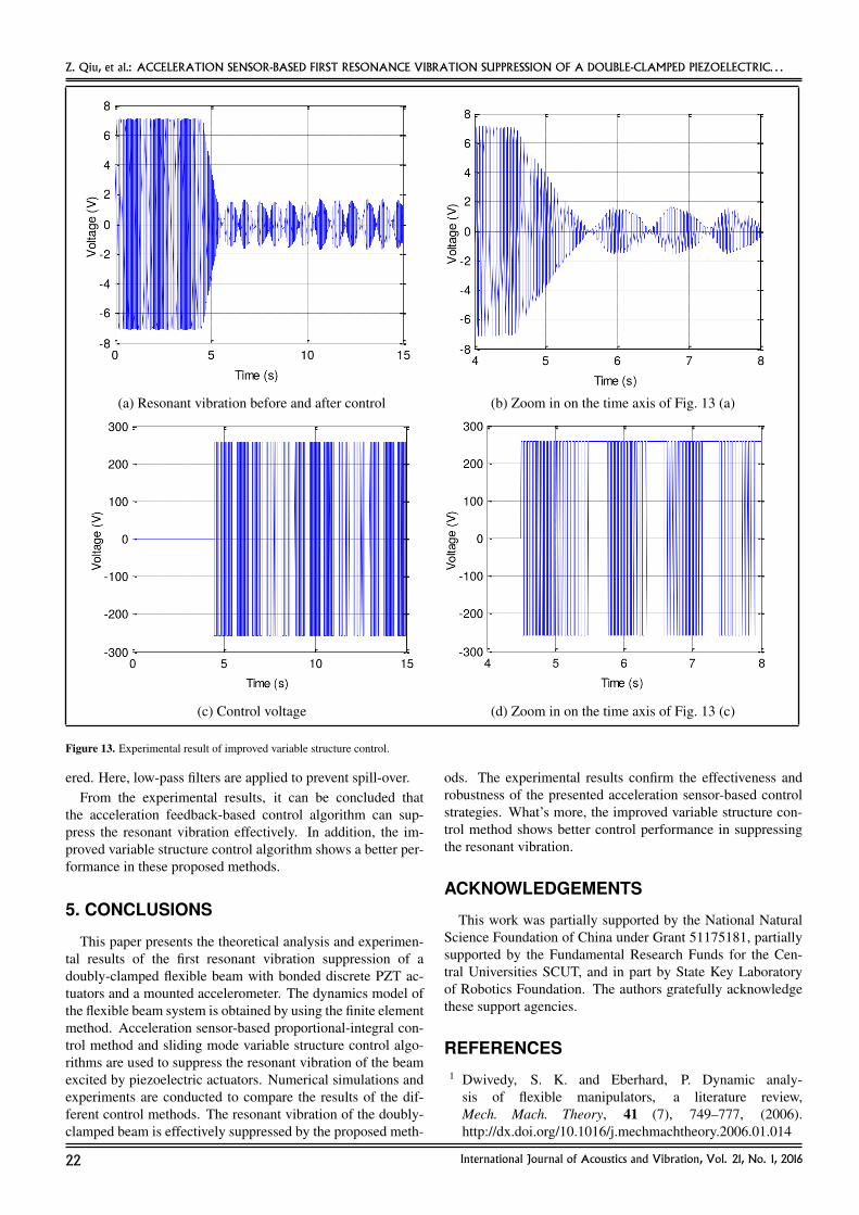
When using the improved variable structure control algo-rithm, the parameters are selected as c1 = 0.6, c2 = 0.04,ε = 2.5, and q = 1.8. Figure 13 (a) shows the time-domain res-onant vibration response before and after control. Figure 13 (c)shows the control voltage applied on the PZT actuators. Fig-ures 13 (b) and 13 (d) are the enlarged view of Figs. 13 (a) and(c) from 4 seconds to 8 seconds, respectively. After the activecontrol is applied, the vibration is suppressed. When the vibra-tion is stable, the vibration amplitude increases and decreasesperiodically, and the maximum vibration amplitude is 1.6 V. Asdepicted in Fig. 13 (c), when the active control is applied, thecontrol voltage is saturated continuously. This is why there is abuilding time where switch does not happen. The experimen-tal results are in good accordance with the simulation resultsto some degree.
Remarks: The parameters of the designed controllers areprovided by trial and error method in simulations and exper-iments. To guarantee the stability conditions of the controllers,control spill-over for higher-mode vibrations should be consid-
International Journal of Acoustics and Vibration, Vol. 21, No. 1, 2016 21
Z. Qiu, et al.: ACCELERATION SENSOR-BASED FIRST RESONANCE VIBRATION SUPPRESSION OF A DOUBLE-CLAMPED PIEZOELECTRIC. . .
(a) Resonant vibration before and after control (b) Zoom in on the time axis of Fig. 13 (a)
(c) Control voltage (d) Zoom in on the time axis of Fig. 13 (c)
Figure 13. Experimental result of improved variable structure control.
ered. Here, low-pass filters are applied to prevent spill-over.From the experimental results, it can be concluded that
the acceleration feedback-based control algorithm can sup-press the resonant vibration effectively. In addition, the im-proved variable structure control algorithm shows a better per-formance in these proposed methods.
5. CONCLUSIONS
This paper presents the theoretical analysis and experimen-tal results of the first resonant vibration suppression of adoubly-clamped flexible beam with bonded discrete PZT ac-tuators and a mounted accelerometer. The dynamics model ofthe flexible beam system is obtained by using the finite elementmethod. Acceleration sensor-based proportional-integral con-trol method and sliding mode variable structure control algo-rithms are used to suppress the resonant vibration of the beamexcited by piezoelectric actuators. Numerical simulations andexperiments are conducted to compare the results of the dif-ferent control methods. The resonant vibration of the doubly-clamped beam is effectively suppressed by the proposed meth-
ods. The experimental results confirm the effectiveness androbustness of the presented acceleration sensor-based controlstrategies. What’s more, the improved variable structure con-trol method shows better control performance in suppressingthe resonant vibration.
ACKNOWLEDGEMENTS
This work was partially supported by the National NaturalScience Foundation of China under Grant 51175181, partiallysupported by the Fundamental Research Funds for the Cen-tral Universities SCUT, and in part by State Key Laboratoryof Robotics Foundation. The authors gratefully acknowledgethese support agencies.
REFERENCES1 Dwivedy, S. K. and Eberhard, P. Dynamic analy-
sis of flexible manipulators, a literature review,Mech. Mach. Theory, 41 (7), 749–777, (2006).http://dx.doi.org/10.1016/j.mechmachtheory.2006.01.014
22 International Journal of Acoustics and Vibration, Vol. 21, No. 1, 2016

Z. Qiu, et al.: ACCELERATION SENSOR-BASED FIRST RESONANCE VIBRATION SUPPRESSION OF A DOUBLE-CLAMPED PIEZOELECTRIC. . .
2 Lin, J. and Liu, W. Z. Experimental evaluation of a piezo-electric vibration absorber using a simplified fuzzy con-troller in a cantilever beam, J. Sound Vib., 296 (3), 567–582,(2006). http://dx.doi.org/10.1016/j.jsv.2006.01.066
3 Chang, W., Gopinathan, S. V., Varadan, V. V., and Varadan,V. K. Design of robust vibration controller for a smart panelusing finite element model, J. Vib. Acoust., 124 (2), 265–276, (2002). http://dx.doi.org/10.1115/1.1448319
4 Hurlebaus, S. and Gaul, L. Smart struc-ture dynamiequations (12) and (13)cs, Mech.Syst. Signal Pr., 20 (2), 255–281, (2006).http://dx.doi.org/10.1016/j.ymssp.2005.08.025
5 Wang, S., Quek, S., Ang, K. Vibration control of smartpiezoelectric composite plates, Smart Mater. Struct., 10 (4),637, (2001). http://dx.doi.org/10.1088/0964-1726/10/4/306
6 Sabatini, M., Gasbarri, P., Monti, R., and Palmerini, G. B.Vibration control of a flexible space manipulator during onorbit operations, Acta Astronaut., 73 (4), 109–121, (2012).http://dx.doi.org/10.1016/j.actaastro.2011.11.012
7 Vasques, C. H., da Conceicao, S. M., de Abreu, G. L. C.M., et al. Identification and vibration control of a flexiblestructure, ABCM Symposium Series in Mechatronics, 4 (2),157–165, (2012).
8 Parameswaran, A. P. and Gangadharan, K. Active vi-bration control of a smart cantilever beam at reso-nance: A comparison between conventional and realtime control, Proc. Intelligent Systems Design andApplications (ISDA), Kochi, India, (2012), 235–239.http://dx.doi.org/10.1109/isda.2012.6416543
9 Mahmoodi, S. N. and Ahmadian, M. Modified acceler-ation feedback for active vibration control of aerospacestructures, Smart Mater. Struct., 19 (6), 065015, (2010).http://dx.doi.org/10.1088/0964-1726/19/6/065015
10 Nima Mahmoodi, S., Craft, M. J., Southward, S. C., andAhmadian, M. Active vibration control using optimizedmodified acceleration feedback with adaptive line enhancerfor frequency tracking, J. Sound Vib., 330 (7), 1300–1311,(2011). http://dx.doi.org/10.1016/j.jsv.2010.10.013
11 Kwak, S. K., Washington, G., and Yedavalli R. K. Ac-celeration feedback-based active and passive vibrationcontrol of landing gear components, J. Aerospace Eng.,15 (1), 1–9, (2002). http://dx.doi.org/10.1061/(asce)0893-1321(2002)15:1(1)
12 Preumont, A. and Loix, N. Active damping of a stiff beam-like structure with acceleration feedback, Exp. Mech., 34(1), 23–26, (1994). http://dx.doi.org/10.1007/bf02328438
13 Gatti, G., Brennan, M. J., and Gardonio, P. Active dampingof a beam using a physically collocated accelerometer andpiezoelectric patch actuator, J. Sound Vib., 303 (3), 798–813, (2007). http://dx.doi.org/10.1016/j.jsv.2007.02.006
14 Shin, C., Hong C., and Jeong W. B. Active vibration controlof beam structures using acceleration feedback control withpiezoceramic actuators, J. Sound Vib., 331 (6), 1257–1269,(2012). http://dx.doi.org/10.1016/j.jsv.2011.11.004
15 Qiu, Z. C., Han, J. D., Zhang, X. M., et al. Ac-tive vibration control of a flexible beam using a non-collocated acceleration sensor and piezoelectric patchactuator, J. Sound Vib., 326 (3), 438–455, (2009).http://dx.doi.org/10.1016/j.jsv.2009.05.034
16 Qiu, Z. C., Wu, H. X., and Ye, C. D. Acceler-ation sensors based modal identification and ac-tive vibration control of flexible smart cantileverplate, Aerosp. Sci. Tech., 13 (6), 277–290, (2009).http://dx.doi.org/10.1016/j.ast.2009.05.003
17 Chatterjee, S. Vibration control by recursive time-delayedacceleration feedback, J. Sound Vib., 317 (1), 67–90,(2008). http://dx.doi.org/10.1016/j.jsv.2008.03.020
18 Ramu, I. and Mohanty, S. Study on free vibrationanalysis of rectangular plate structures using finite el-ement method, Procedia Eng., 38, 2758–2766, (2012).http://dx.doi.org/10.1016/j.proeng.2012.06.323
19 Alkhatib, R. and Golnaraghi, M. Active structural vibra-tion control: a review, Shock Vib. Digest, 35 (5), 367–383,(2003). http://dx.doi.org/10.1177/05831024030355002
20 Benjeddou, A. Advances in piezoelectric finite el-ement modeling of adaptive structural elements:a survey, Comput. Struct., 2000, 76 (1), 347–363.http://dx.doi.org/10.1016/s0045-7949(99)00151-0
21 Yasin, M. Y., Ahmad N., and Alam, M. N. Finite el-ement analysis of actively controlled smart plate withpatched actuators and sensors, Lat. Am J. Solids Struct.,7 (3), 227–247, (2010). http://dx.doi.org/10.1590/s1679-78252010000300001
22 Lam, K., Peng, X., Liu G., and Reddy, J. N. Afinite-element model for piezoelectric composite lami-nates, Smart Mater. Struct., 6 (5), 583–591, (1997).http://dx.doi.org/10.1088/0964-1726/6/5/009
23 Bandyopadhyay, B., Manjunath, T. C., and Umapathy, M.Modeling, control and implementation of smart structures:a FEM-state space approach, Springer-Verlag, Berlin,(2007).
24 Hung, J. Y., Gao W., and Hung J. C. Variable structure con-trol: a survey, IEEE Transactions on Indust. Elect., 1993,40 (1), 2–22. http://dx.doi.org/10.1109/41.184817
25 Fung, E. H. and Lee, C. K. Variable structure track-ing control of a single-link flexible arm using timevarying sliding surface, J. Robotic Syst., 1999, 16(12), 715–726. http://dx.doi.org/10.1002/(sici)1097-4563(199912)16:12<715::aid-rob4>3.3.co;2-y
International Journal of Acoustics and Vibration, Vol. 21, No. 1, 2016 23