acceptable permissible limits for trans and reactors
TRANSCRIPT

8/12/2019 Acceptable Permissible Limits for Trans and Reactors
http://slidepdf.com/reader/full/acceptable-permissible-limits-for-trans-and-reactors 1/13
8/12/2019 Acceptable Permissible Limits for Trans and Reactors
http://slidepdf.com/reader/full/acceptable-permissible-limits-for-trans-and-reactors 2/13
8/12/2019 Acceptable Permissible Limits for Trans and Reactors
http://slidepdf.com/reader/full/acceptable-permissible-limits-for-trans-and-reactors 3/13
8/12/2019 Acceptable Permissible Limits for Trans and Reactors
http://slidepdf.com/reader/full/acceptable-permissible-limits-for-trans-and-reactors 4/13

8/12/2019 Acceptable Permissible Limits for Trans and Reactors
http://slidepdf.com/reader/full/acceptable-permissible-limits-for-trans-and-reactors 5/13
Doc. No. D-5-02-XX-02-00 Rev.0
ACCEPTABLE / PERMISSIBLE LIMITS FOR TRANSFORMERS & REACTORS
1
ACCEPTABLE / PERMISSIBLE LIMITS FOR TRANSFORMERS & REACTORS
A. Permissible Limits for parameters of tests to be carried out at Substation
SR
NO
EQUIPMENT / TEST DATA PERMISSIBLE LIMITS REFERENCE
1. Capacitance for Bushings
Main capacitance (C1)
Within -5 % to +10 % Variation of previous test result POWERGRID Doc. No.: D-2-03-XX-01-01 Rev.01
2. Tan Delta for Bushing at 20ºC Less than 0.007 IEC – 60137 ed.2003
3. Contact Resistance of Bushing 10 Micro-Ohm /Connector POWERGRID Doc. No.: D-2-01-03-01-01 Rev.01
4. Tan Delta for Windings at 20 ºC Less than 0.007 IEEE/C57.12.90.1999
5. Rate of Rise of Tan Delta (Bushing &Winding) 0.001 Per year (Max.) POWERGRID Doc. No.: D-2-03-XX-01-01 Rev.01
6. Magnetizing current Test (ExcitationCurrent Test)
If the excitation current is less than 50 milli-amperes (mA), thedifference between the two higher currents should be less than10%. If the excitation current is more than 50 mA, the differenceshould be less than 5%.
An agreement to within 25% of the measured exciting current withthe previous test is usually considered satisfactory. In general, if
there is an internal problem, these differences will be greater(more than 50 times).
POWERGRID Doc. No.: D-2-03-XX-01-01 Rev.01
7. Magnetic Balance Test (Single Phase) Value of supply voltage (230 V AC) in one phase is equal to sumvoltage induced in other two phases. When supply voltageapplied in middle limb, voltage induced in outer limbs shouldequal and roughly half of the supply voltage.
Zero voltage or very negligible voltage induced in the other twowindings should be investigated
POWERGRID Doc. No.: D-2-03-XX-01-01 Rev.01

8/12/2019 Acceptable Permissible Limits for Trans and Reactors
http://slidepdf.com/reader/full/acceptable-permissible-limits-for-trans-and-reactors 6/13
Doc. No. D-5-02-XX-02-00 Rev.0
ACCEPTABLE / PERMISSIBLE LIMITS FOR TRANSFORMERS & REACTORS
2
SR
NO
EQUIPMENT / TEST DATA PERMISSIBLE LIMITS REFERENCE
Magnetic Balance Test (Continued) Normally, the voltage induced in the center phase shall be 50 to 90% ofthe applied voltage. However, when the center phase is excited thenthe voltage induced in the outer phases shall be 30 to 70% of the
applied voltage
8. DC Winding resistance (Resistance to beconverted to 75 ºC)
± 5% variation between phases or from Factory test results POWERGRID Doc. No.: D-2-03-XX-01-01 Rev.01
9. Voltage Ratio of Transformer (All Taps) Within ± 0.5% variation from specified values or Factory test results
Trend of voltage ratio values with reference to the ratio valuesmeasured during the commissioning tests may also be considered
POWERGRID Doc. No.: D-2-03-XX-01-01 Rev.01
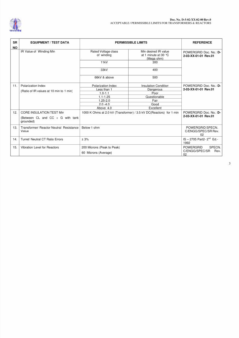
10. INSULATION VALUE ( THUMB RULE/EMPIRICAL FORMULA)
Min insulation Values for one minute insulation resistancemeasurements for transformers may be determined by using thefollowing empirical formula:
R = CE / √KVA Where
R = Insulation resistance, in MΩ
C = 1.5 for oil-filled transformers at 20°C, assuming that thetransformer’s insulating oil is dry, acid free, and sludge free = 30.0 forun-tanked oil-impregnated transformers
E = Voltage rating, in V, of one of the single-phase windings( Ph-to-Phfor delta connected and ph-to-neutral for wye connected transformers)
KVA = Rated capacity of the winding under test (If the winding undertest is three-phase and the three individual windings are beingtested as one, the rated capacity of three-phase winding is used
POWERGRID Doc. No.: D-
2-03-XX-01-01 Rev.01
8/12/2019 Acceptable Permissible Limits for Trans and Reactors
http://slidepdf.com/reader/full/acceptable-permissible-limits-for-trans-and-reactors 7/13
8/12/2019 Acceptable Permissible Limits for Trans and Reactors
http://slidepdf.com/reader/full/acceptable-permissible-limits-for-trans-and-reactors 8/13
Doc. No. D-5-02-XX-02-00 Rev.0
ACCEPTABLE / PERMISSIBLE LIMITS FOR TRANSFORMERS & REACTORS
4
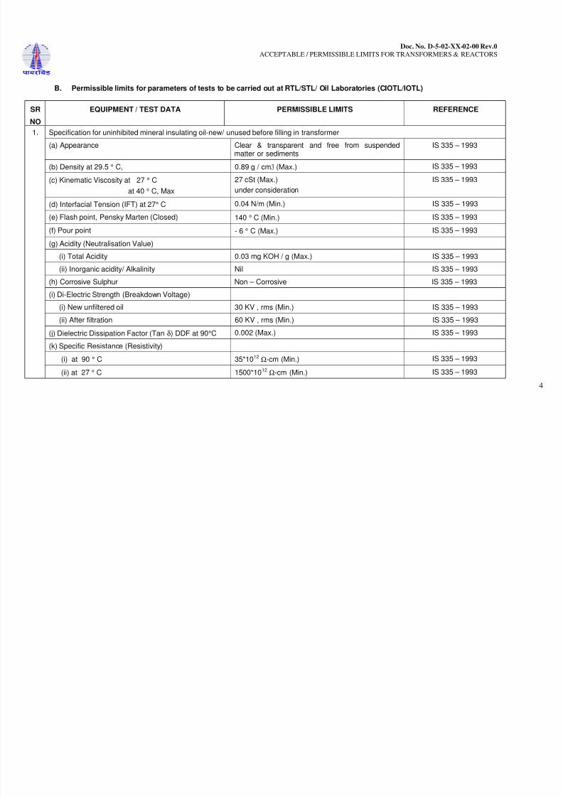
B. Permissible limits for parameters of tests to be carried out at RTL/STL/ Oil Laboratories (CIOTL/IOTL)
SR
NO
EQUIPMENT / TEST DATA PERMISSIBLE LIMITS REFERENCE
Specification for uninhibited mineral insulating oil-new/ unused before filling in transformer
(a) Appearance Clear & transparent and free from suspended
matter or sediments
IS 335 – 1993
(b) Density at 29.5 ° C, 0.89 g / cm3 (Max.) IS 335 – 1993
(c) Kinematic Viscosity at 27 ° C
at 40 ° C, Max
27 cSt (Max.)
under consideration
IS 335 – 1993
(d) Interfacial Tension (IFT) at 27° C 0.04 N/m (Min.) IS 335 – 1993
(e) Flash point, Pensky Marten (Closed) 140 ° C (Min.) IS 335 – 1993
(f) Pour point - 6 ° C (Max.) IS 335 – 1993
(g) Acidity (Neutralisation Value)
(i) Total Acidity 0.03 mg KOH / g (Max.) IS 335 – 1993
(ii) Inorganic acidity/ Alkalinity Nil IS 335 – 1993
(h) Corrosive Sulphur Non – Corrosive IS 335 – 1993
(i) Di-Electric Strength (Breakdown Voltage)
(i) New unfiltered oil 30 KV , rms (Min.) IS 335 – 1993
(ii) After filtration 60 KV , rms (Min.) IS 335 – 1993
1.
(j) Dielectric Dissipation Factor (Tan δ) DDF at 90°C 0.002 (Max.) IS 335 – 1993
(k) Specific Resistance (Resistivity)
(i) at 90 ° C 35*1012 Ω-cm (Min.) IS 335 – 1993
(ii) at 27 ° C 1500*1012 Ω-cm (Min.) IS 335 – 1993

8/12/2019 Acceptable Permissible Limits for Trans and Reactors
http://slidepdf.com/reader/full/acceptable-permissible-limits-for-trans-and-reactors 9/13
Doc. No. D-5-02-XX-02-00 Rev.0
ACCEPTABLE / PERMISSIBLE LIMITS FOR TRANSFORMERS & REACTORS
5
SR
NO
EQUIPMENT / TEST DATA PERMISSIBLE LIMITS REFERENCE
(l) Oxidation Stability
(i) Neutralization Value after Oxidation 0.40 mg KOH / g (Max.) IS 335 – 1993
(ii) Total sludge after Oxidation 0.1 % by weight (Max.) IS 335 – 1993(m) Ageing characteristics after accelerated ageing
(Open Breaker method with copper catalyst)
(i) Specific Resistance (Resistivity)
at 27 ° C 2.5*1012Ω-cm (Min.) IS 335 – 1993
at 90 ° C 0.2*1012Ω-cm (Min.) IS 335 – 1993
(ii) Dielectric Dissipation Factor (Tan δ) at 90 °C 0.2 (Max.) IS 335 – 1993
(iii) Total Acidity 0.05 mg KOH/ g (Max.) IS 335 – 1993
(iv) Total Sludge 0.05 % by weight (Max.) IS 335 – 1993
(n) Water content of New unfiltered oil 50 ppm (Max.) IS 335 – 1993
(o) PCA Content (Polycyclic Aromatics) 3 % by mass (Max.) IEC- 60296, 2003
(p) Presence of Oxidation Inhibitor Oil shall not contain antioxidant additives. Value of0.05 % by mass (Max.) shall be treated as absence
of DBPC- Phenolic type inhibitor
IS 335 – 1993
(q) PCB Content (Polychlorinated Biphenyls) Not detectable
0.1 mg/ kg (Max.)
IEC- 60296, 2003
(r) Dissolved Gas Analysis (DGA) Not applicable IS 335 – 1993
(s) 2 – Furfural (Furan Analysis, Test Method – IEC61198:1993)
0.1 mg/ kg (Max.) IEC- 60296, 2003
8/12/2019 Acceptable Permissible Limits for Trans and Reactors
http://slidepdf.com/reader/full/acceptable-permissible-limits-for-trans-and-reactors 10/13
Doc. No. D-5-02-XX-02-00 Rev.0
ACCEPTABLE / PERMISSIBLE LIMITS FOR TRANSFORMERS & REACTORS
6
SR
NO
EQUIPMENT / TEST DATA PERMISSIBLE LIMITS REFERENCE
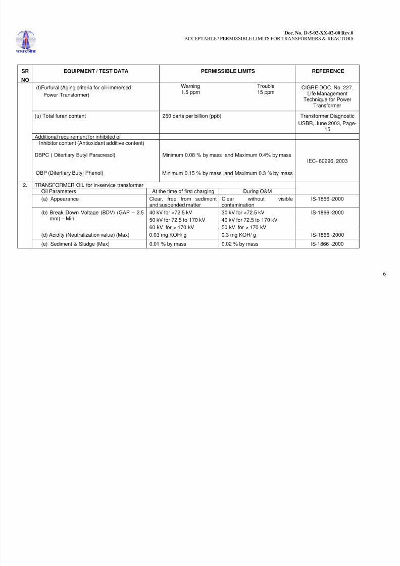
(t)Furfural (Aging criteria for oil-immersed
Power Transformer)
Warning Trouble1.5 ppm 15 ppm
CIGRE DOC. No. 227.Life Management
Technique for PowerTransformer
(u) Total furan content 250 parts per billion (ppb) Transformer Diagnostic
USBR, June 2003, Page-15
Additional requirement for inhibited oil
Minimum 0.08 % by mass and Maximum 0.4% by mass
IEC- 60296, 2003
Inhibitor content (Antioxidant additive content)
DBPC ( Ditertiary Butyl Paracresol)
DBP (Ditertiary Butyl Phenol) Minimum 0.15 % by mass and Maximum 0.3 % by mass
TRANSFORMER OIL for in-service transformerOil Parameters At the time of first charging During O&M
2.
(a) Appearance Clear, free from sedimentand suspended matter
Clear without visiblecontamination
IS-1866 -2000
(b) Break Down Voltage (BDV) (GAP – 2.5mm) – Min
40 kV for <72.5 kV
50 kV for 72.5 to 170 kV
60 kV for > 170 kV
30 kV for <72.5 kV
40 kV for 72.5 to 170 kV
50 kV for > 170 kV
IS-1866 -2000
(d) Acidity (Neutralization value) (Max) 0.03 mg KOH/ g 0.3 mg KOH/ g IS-1866 -2000
(e) Sediment & Sludge (Max) 0.01 % by mass 0.02 % by mass IS-1866 -2000
8/12/2019 Acceptable Permissible Limits for Trans and Reactors
http://slidepdf.com/reader/full/acceptable-permissible-limits-for-trans-and-reactors 11/13
Doc. No. D-5-02-XX-02-00 Rev.0
ACCEPTABLE / PERMISSIBLE LIMITS FOR TRANSFORMERS & REACTORS
7
SR
NO
EQUIPMENT / TEST DATA PERMISSIBLE LIMITS REFERENCE
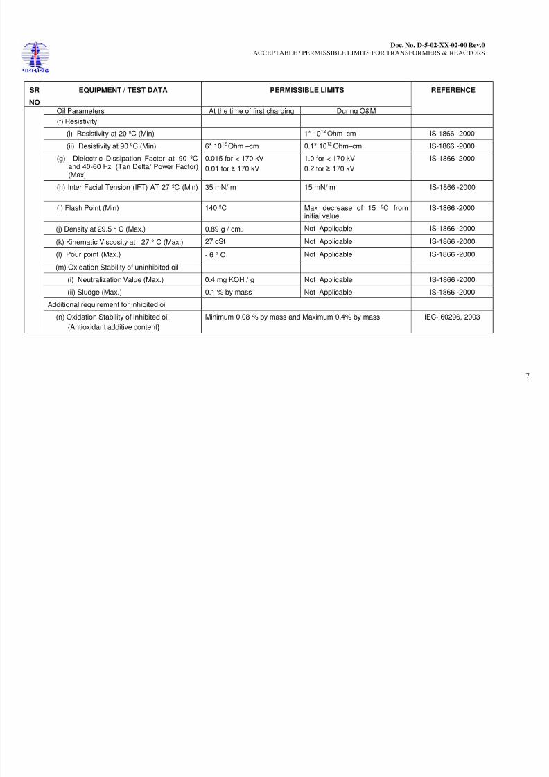
Oil Parameters At the time of first charging During O&M
(f) Resistivity
(i) Resistivity at 20 ºC (Min) 1* 1012 Ohm–cm IS-1866 -2000
(ii) Resistivity at 90 ºC (Min) 6* 10
12
Ohm –cm 0.1* 10
12
Ohm–cm IS-1866 -2000(g) Dielectric Dissipation Factor at 90 ºC
and 40-60 Hz (Tan Delta/ Power Factor)(Max)
0.015 for < 170 kV
0.01 for 170 kV
1.0 for < 170 kV
0.2 for 170 kV
IS-1866 -2000
(h) Inter Facial Tension (IFT) AT 27 ºC (Min)
35 mN/ m 15 mN/ m IS-1866 -2000
(i) Flash Point (Min) 140 ºC Max decrease of 15 ºC frominitial value
IS-1866 -2000
(j) Density at 29.5 ° C (Max.) 0.89 g / cm3 Not Applicable IS-1866 -2000
(k) Kinematic Viscosity at 27 ° C (Max.) 27 cSt Not Applicable IS-1866 -2000
(l) Pour point (Max.) - 6 ° C Not Applicable IS-1866 -2000
(m) Oxidation Stability of uninhibited oil
(i) Neutralization Value (Max.) 0.4 mg KOH / g Not Applicable IS-1866 -2000
(ii) Sludge (Max.) 0.1 % by mass Not Applicable IS-1866 -2000
Additional requirement for inhibited oil
(n) Oxidation Stability of inhibited oil
Antioxidant additive content
Minimum 0.08 % by mass and Maximum 0.4% by mass IEC- 60296, 2003

8/12/2019 Acceptable Permissible Limits for Trans and Reactors
http://slidepdf.com/reader/full/acceptable-permissible-limits-for-trans-and-reactors 12/13
Doc. No. D-5-02-XX-02-00 Rev.0
ACCEPTABLE / PERMISSIBLE LIMITS FOR TRANSFORMERS & REACTORS
8
SR
NO
EQUIPMENT / TEST DATA PERMISSIBLE LIMITS REFERENCE
Dissolved Gas Analysis (DGA)
Typical rates of gas increase for Powertransformers
Values in milliliters per day
Hydrogen (H2) <5Methane (CH4) <2Ethane(C2H6) <2Ethylene (C2H4) <2Acetylene (C2H2) <0.1Carbon Monoxide (CO) <50
3.
Carbon Dioxide (CO2) <200
Equation to calculate the rate of gas increase as per IEC: 60599-1999
Rate = (Y2 - Y1)m / (d2 - d1) ml/ dayWhereY1 = is the reference analysisY2 = is the last analysis(Y2 - Y1) = is the increase in micro-litre per litrem = is the mass of oil , in kilograms = is the mass density, in kilograms per cubic metred2 = is the date for Y1 d1 = is the date for Y2
IEC: 60599-1999
Given only for guidelinesand for information
Interpretation of DGAresults need to be
reviewed by CC/OS orDGA Committee
4. Moisture measurement of Winding (RVMMeasurement)
IEEE Std. 62-1995
Insulation condition % Moisture by dryweight in paper (Wp)
% Water saturationof oil ( RS )
Dry (at commissioning) 0.5-1.0 % < 5 %Normal in operation < 2 %Wet 2-4 % 6-20 %Extremely wet > 4.5 % > 30 %
CIGRE DOC. No. 227.Life Management
Technique for PowerTransformer
8/12/2019 Acceptable Permissible Limits for Trans and Reactors
http://slidepdf.com/reader/full/acceptable-permissible-limits-for-trans-and-reactors 13/13
Doc. No. D-5-02-XX-02-00 Rev.0
ACCEPTABLE / PERMISSIBLE LIMITS FOR TRANSFORMERS & REACTORS
9
SR
NO
EQUIPMENT / TEST DATA PERMISSIBLE LIMITS REFERENCE
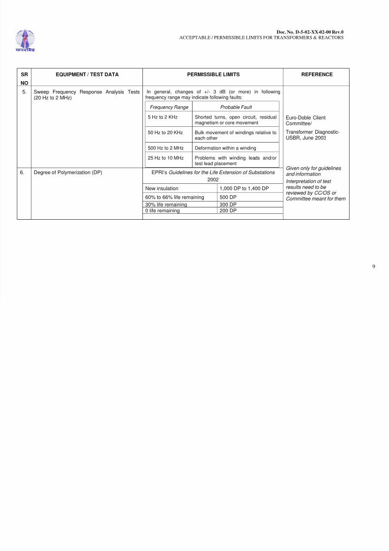
5. Sweep Frequency Response Analysis Tests(20 Hz to 2 MHz)
In general, changes of +/- 3 dB (or more) in followingfrequency range may indicate following faults:
Frequency Range Probable Fault
5 Hz to 2 KHz Shorted turns, open circuit, residualmagnetism or core movement
50 Hz to 20 KHz Bulk movement of windings relative toeach other
500 Hz to 2 MHz Deformation within a winding
25 Hz to 10 MHz Problems with winding leads and/ortest lead placement
6. Degree of Polymerization (DP) EPRI’s Guidelines for the Life Extension of Substations
2002
New insulation 1,000 DP to 1,400 DP
60% to 66% life remaining 500 DP
30% life remaining 300 DP
0 life remaining 200 DP
Euro-Doble ClientCommittee/
Transformer Diagnostic-USBR, June 2003
Given only for guidelinesand information
Interpretation of testresults need to bereviewed by CC/OS orCommittee meant for them