access protocols adaptation to massive machine-to-machine
TRANSCRIPT
UNIVERSIDADE FEDERAL DO RIO GRANDE DO SUL INSTITUTO DE INFORMÁTICA
CURSO DE ENGENHARIA DE COMPUTAÇÃO
MATHEUS MARRONE CASTANHO
Access Protocols Adaptation to massive Machine-to-Machine
Communications
Monografia apresentada como requisito parcial para a obtenção do grau de Bacharel em Engenharia de Computação.
Orientador: Prof. Dr. Alexandre da Silva Carissimi
Porto Alegre 2016
UNIVERSIDADE FEDERAL DO RIO GRANDE DO SUL Reitor: Prof. Carlos Alexandre Netto Vice-Reitor: Prof. Rui Vicente Oppermann Pró-Reitor de Graduação: Prof. Vladimir Pinheiro do Nascimento Diretor do Instituto de Informática: Prof. Luís da Cunha Lamb Coordenador do Curso de Engenharia de Computação: Prof. Raul Fernando Weber Bibliotecária-Chefe do Instituto de Informática: Beatriz Regina Bastos Haro
Access Protocols Adaptation to massive Machine-to-
Machine Communications – Resumo Estendido
Matheus M. Castanho
Instituto de Informática – Universidade Federal do Rio Grande do Sul (UFRGS)
Caixa Postal 15.064 – 91.501-970 – Porto Alegre – RS – Brazil
1. Introdução
O desenvolvimento das telecomunicações e da indústria de microeletrônica permitiu uma forte expansão das comunicações do tipo máquina-máquina (M2M) nos últimos anos. A comunicação entre dispositivos eletrônicos sem a intervenção humana introduziu um novo conceito global, a Internet das Coisas (do inglês IoT – Internet of
Things). Esses dispositivos estão presentes em vários setores da indústria, devido aos processos de automatização e monitoramento.
Com a popularização da IoT, há uma necessidade de se buscar uma conexão rápida e confiável entre milhares de dispositivos e uma estação de base para a troca e análise de informações. Dentre os diferentes tipos de tecnologia existentes atualmente, as redes de celulares aparecem como a escolha mais apropriada para trabalhar com os dispositivos M2M em larga escala. Pesquisas para o desenvolvimento da próxima geração de rede de celulares já começaram e essa tecnologia futura, o 5G, poderá integrar de forma completa e eficiente as comunicações M2M. Por enquanto, pode-se trabalhar com a tecnologia já existente do LTE (Long-Term-Evolution), aproveitando sua infraestrutura já implantada.
No entanto, as novas tecnologias e o crescente número de dispositivos inteligentes indicam que um cenário com centenas de milhares de dispositivos é iminente. O padrão atual do LTE não foi desenvolvido para suportar cenários com um acesso massivo de dispositivos. O LTE foi criado, inicialmente, como um tipo de comunicação voltado para seres humanos e, por isso, seu procedimento de acesso aleatório não é suficiente para suportar uma enorme quantidade de dispositivos que tentam acessar a rede. Esse procedimento faz parte do mecanismo de controle de acesso ao meio (MAC) da camada de enlace da rede.
O LTE precisa ser adaptado para o contexto M2M, permitindo que vários dispositivos possam se conectar à rede. O procedimento de acesso aleatório é o mecanismo a ser modificado para que haja suporte a acessos massivos. As melhorias que venham a ser realizadas não podem interferir no funcionamento atual do LTE para as aplicações humanas. A solução precisará garantir o suporte para ambos os tipos de comunicação.
O propósito deste trabalho é projetar um novo mecanismo para a camada de enlace que introduza mudanças no processo de acesso aleatório, que reduza a sobrecarga da rede em cenários com alto volume de tráfego e lida com o problema de colisões. Esse novo mecanismo faca nas características das comunicações M2M como pequenas transmissões de dados, eficácia energética e garantia de qualidade de serviço

para os diferentes tipos de aplicações. O protocolo também deverá suportar ambas as comunicações máquina-máquina e humano-humano (H2H).
O presente trabalho foi desenvolvido como projeto de final de curso para a universidade francesa INP (Institut National Polytecnique) de Grenoble, avaliado pela faculdade francesa PHELMA. Este projeto será utilizado como trabalho de conclusão do curso de Engenharia de Computação da UFRGS, no âmbito do acordo de dupla diplomação pelo programa de intercâmbio BRAFITEC. Este projeto foi elaborado em parceria com o CEA (Commissariat à l’énergie atomique et aux énergies alternatives) e a escola de física, de eletrônica e de materiais, PHELMA e foi realizado no ano de 2015, entre os meses de março e agosto, na cidade de Grenoble, França.
2. Fundamentação Teórica e Conceitos
Nesta seção serão abordados alguns dos principais conceitos presentes neste trabalho, como as comunicações M2M e suas diferenças para as comunicações H2H. As principais características do LTE serão apresentadas, juntamente com o funcionamento do protocolo de acesso aleatório.
2.1 Comunicações M2M e H2H
As comunicações do tipo M2M são realizadas entre as máquinas sem a intervenção humana, com a troca de dados em uma rede formada por diversos dispositivos. Essas máquinas são compostas por sensores que capturam alguma característica do meio em que estão e transmitem seus dados para aplicações que tratarão as informações capturadas. As principais características do M2M são: número elevado de dispositivos, baixo consumo energético, pacotes de dados pequenos e conexão direcionada ao uplink.
As comunicações humano-humano estão presentes no uso de dispositivos como smartphones e tablets, e têm como objetivo realizar a troca de dados entre esses dispositivos e as pessoas. Chamadas de áudio e vídeo são um exemplo de comunicação humano-humano. As principais características deste tipo de comunicação são: grandes pacotes de dados, pequena quantidade de dispositivos, elevado consumo energético e comunicação bidirecional (downlink e uplink).
2.2 Características do LTE
O LTE é um padrão para redes sem fio de alta velocidade que foi criado para substituir o GSM/HSPA e hoje é amplamente usado em redes celulares, chamado comercialmente de 4G. O LTE mantém a compatibilidade com as antigas versões das redes de celulares.
O LTE utiliza o procedimento de acesso aleatório como mecanismo de controle de acesso ao meio. Esse protocolo é responsável pela conexão dos dispositivos com uma estação de base e utiliza preâmbulos para estabelecer a conexão.
Os preâmbulos são sequências codificadas que definem os intervalos de tempo da janela de transmissão em que o dispositivo pode transmitir. Existem 64 preâmbulos e cada um define uma certa quantidade de intervalos possíveis. A figura 1 mostra seis preâmbulos diferentes e os intervalos de tempo em que a transmissão pode ser feita. O dispositivo que selecionar o preâmbulo de índice 0 pode transmitir apenas em um intervalo de 1 ms a cada duas janelas de 10 ms, enquanto que o dispositivo que

selecionar o preâmbulo de índice 14 pode transmitir em todos os intervalos de 1 ms da janela.
Figura 1. Configuração dos Preâmbulos
O procedimento de acesso aleatório é composto pela troca de quatro mensagens entre o dispositivo que tenta acessar a rede e a estação de base que controla esse acesso. Antes de começar uma conexão, a estação de base irá informar para cada dispositivo quais os preâmbulos disponíveis que poderão ser selecionados de forma aleatória. O dispositivo irá selecionar um preâmbulo e enviará a primeira mensagem no intervalo de tempo definido pelo preâmbulo selecionado. A estação de base irá receber essa primeira mensagem que contém o preâmbulo selecionado e irá alocar um único recurso para essa conexão. Um recurso é um intervalo de tempo que será utilizado para receber a requisição de conexão de um dispositivo qualquer. Após alocar o recurso, a estação de base irá providenciar uma mensagem de resposta (segunda mensagem). Essa mensagem será recebida por todos os dispositivos que enviaram o mesmo preâmbulo ao mesmo tempo. Uma vez que uma máquina que solicitou a conexão receba a mensagem de resposta da estação de base, ela estará pronta para enviar a mensagem contendo a requisição de conexão (terceira mensagem). A estação de base irá receber essa requisição no recurso (intervalo de tempo) alocado para o dispositivo solicitante e depois enviará uma última mensagem para confirmar a conexão. Ao receber a confirmação, o dispositivo estará conectado à rede.
Esse protocolo apresenta problemas de congestionamento em cenários com diversos dispositivos tentando acessar a rede, uma vez que aumenta a probabilidade de dois ou mais dispositivos selecionarem um mesmo preâmbulo e transmitirem no mesmo intervalo de tempo. Se dois ou mais dispositivos enviarem o mesmo preâmbulo, no mesmo intervalo de tempo, mas a estação de base não receber ao mesmo tempo, esta irá considerar uma colisão na mensagem do preâmbulo, devido a uma interferência destrutiva dos sinais recebidos e, portanto, ela não irá alocar recurso para nenhuma das máquinas solicitantes. Mas se as mensagens chegarem ao mesmo tempo, gerando assim uma interferência construtiva do sinal, a estação de base irá perceber apenas um sinal e então ela não irá considerar que não houve colisão. Quando esta situação ocorre, a estação de base irá alocar apenas um recurso e informará a todos os dispositivos que enviaram a mensagem o mesmo recurso alocado. Esses dispositivos irão enviar a
requisição de conexão para o mesmo recurso e, então, haverá colisão, impossibilitando os mesmos de acessarem a rede e criando a necessidade de refazer o procedimento de acesso a partir de uma nova seleção de preâmbulo. Essa colisão ocorrerá em tempo, pois para esse projeto não foram consideradas as colisões em frequência, mesmo que o modelo físico utilize uma janela em tempo e em frequência.
3. Arquitetura Proposta e Implementações
Para resolver o problema das colisões, buscou-se na literatura algumas técnicas que pudessem contribuir para uma solução definitiva. Identificou-se um conjunto de técnicas consideradas básicas que estavam presentes em diversas soluções. Essas técnicas isoladamente não produziam melhorias significativas; contudo, a aplicação delas em conjunto, pode ser capaz de trazer um resultado mais expressivo. Dentre dezenas de técnicas estudadas, algumas foram selecionadas por apresentarem soluções interessantes e que serviram de inspiração para este trabalho. A partir dessas técnicas, foi elaborado um quadro comparativo que está presente na tabela 3-4 da seção 3.4 do trabalho de conclusão.
Este trabalho propôs duas soluções para melhorar o mecanismo de acesso ao meio do LTE. A primeira solução consiste em melhorar a seleção de preâmbulos para um grupo de dispositivos, conforme o tráfego na rede; a segunda, visa melhorar o mecanismo de recepção da mensagem do preâmbulo pela estação de base.
Para a primeira solução, fez-se um estudo da quantidade de dispositivos suportada por cada tipo de preâmbulo, para se estimar sua capacidade em termos de nós por taxa de sucesso de transmissão. Cada preâmbulo possui uma quantidade de intervalos de tempo que são usados para a transmissão. Quanto menos intervalos o preâmbulo possuir mais restrito ficarão os dispositivos em relação ao intervalo de tempo em que poderão começar sua transmissão. Portanto, criou-se um mecanismo que fornecesse uma probabilidade de seleção de preâmbulo que correspondesse à quantidade de dispositivos suportado por cada um. Essa ideia partiu da premissa de que alguns dispositivos poderiam ter suas mensagens colididas precocemente ao selecionarem um mesmo preâmbulo que não suportasse muitos dispositivos.
Este projeto agregou um novo mecanismo de detecção de colisões com a segunda solução. No LTE padrão, as colisões são detectadas quando mais de um dispositivo tenta acessar um recurso alocado para a transmissão ou quando duas ou mais mensagens do preâmbulo são recebidas pela estação de base em tempos diferentes. Para evitar este segundo cenário de colisão, criou-se um mecanismo de detecção de colisão para a mensagem do preâmbulo. Com esse mecanismo, a estação de base poderia escolher para qual dos dispositivos que colidiram ela permitiria continuar o procedimento de acesso, através de uma análise da mensagem recebida com a melhor relação sinal-ruído pela estação de base, o que não é feito no padrão LTE atual.
No projeto foi utilizado um simulador de redes sem fio em larga escala orientado à pacote chamado WSNet, um software livre desenvolvido pelo laboratório francês CITI localizado em Lyon. Configurado através de arquivos XML, apresenta um completo sistema modular para uma arquitetura de nós, o qual permite implementar as diferentes camadas do modelo OSI. A arquitetura do simulador pode ser dividida em três blocos: rádio, núcleo de simulação e os nós.

Para este trabalho precisou-se adaptar esse simulador para o contexto do LTE, por isso foram criados os seguintes módulos com características do LTE: antena, modelo de propagação, modulação, camada de aplicação, MAC (Medium Access
Control) e transceptor. Alguns desses módulos foram projetados para representarem apenas os nós dos dispositivos e outros apenas o nó da estação de base. Os módulos do núcleo do simulador também tiveram que ser alterados para que os pacotes não fossem mais duplicados para todos os módulos do simulador.
As duas soluções foram implementadas nos módulos MAC e transceptor do simulador. O primeiro ficou responsável por criar a mensagem de preâmbulo e selecionar o mecanismo de transmissão. O algoritmo era composto de três etapas: seleção do preâmbulo e do canal, cálculo do intervalo de tempo para transmissão e transmissão do pacote. O segundo ficou responsável por acoplar o mecanismo de detecção de colisão para a estação de base.
4. Resultados
No final do projeto, buscou-se utilizar o simulador para verificar o comportamento das soluções propostas nesse trabalho. Para isso, foram criados um conjunto de testes para cada algoritmo. Para a primeira solução, foram feitos testes para cada um dos seis tipos de preâmbulos diferentes, variando-se a quantidade de nós e a periodicidade em que cada nó tentava uma conexão. Para a segunda solução, utilizou-se todos os preâmbulos num mesmo teste, variando-se a quantidade de nós e a periodicidade em que cada nó tentava uma conexão. Foram feitas cem simulações para cada teste.
Inicialmente, analisou-se a taxa de sucesso de transmissão de cada tipo de preâmbulo para certas quantidades de dispositivos, ao se fazer uma simulação com seleção aleatória de preâmbulos. Com base nessa análise, definiu-se a capacidade de cada preâmbulo como sendo a quantidade de dispositivos por ele suportada. Essa capacidade está relacionada com a quantidade de intervalos de tempo para transmissão características de cada preâmbulo. Utilizou-se um algoritmo de seleção de preâmbulos com uma probabilidade correspondente a essa capacidade. Os preâmbulos que apresentavam uma capacidade inferior de transmissão (menos intervalos), receberam uma menor probabilidade de seleção e aqueles que apresentavam uma capacidade superior (mais intervalos) receberam uma maior probabilidade. Os resultados obtidos mostraram um ganho importante na taxa de sucesso de transmissão de cada preâmbulo em relação ao modelo sem probabilidade de seleção. Contudo, em situações de extrema saturação, o desempenho dessa técnica mostrou-se inferior ao modelo sem uso do algoritmo de probabilidade.
Para o teste do segundo algoritmo, verificou-se a taxa de sucesso de transmissão em função da quantidade de dispositivos para cada tipo de preâmbulo. Nos resultados, ficou evidenciado o ganho que o algoritmo de detecção de colisão proposto por este trabalho trouxe em relação ao modelo tradicional do LTE. Também verificou-se um ganho importante com o uso das duas soluções em conjunto.
5. Conclusão
Seguindo as tendências atuais da IoT, cenários com milhares de dispositivos conectados estarão cada vez mais presentes em nosso cotidiano. A infraestrutura atual é o LTE que não suporta comunicações M2M porque seu mecanismo de controle de acesso ao meio é
ineficiente para um grande tráfego M2M. O problema de base encontrado nesse trabalho foi como evitar as colisões causadas por um acesso massivo de dispositivos M2M em uma rede LTE. O objetivo, portanto, deste projeto foi propor soluções para o cénario de grande tráfego M2M sobre a infraestrutura do LTE sem prejudicar as comunicações do tipo H2H, e para isso buscou-se agregar novas técnicas ao mecanismo de controle de acesso ao meio do LTE.
Este trabalho propôs duas soluções para melhorar o procedimento de acesso aleatório do LTE em relação à taxa de sucesso de transmissão. A primeira apresenta uma medição da quantidade de dispositivos suportada por cada preâmbulo, permitindo a criação de um algoritmo responsável por fornecer uma probabilidade de seleção que corresponda à essa quantidade suportada medida para os diferentes preâmbulos. Os resultados mostraram que esta solução trouxe um ganho importante em relação ao mecanismo aleatório de seleção do padrão do LTE. A segunda solução proposta por este trabalho trata-se de um novo mecanismo de detecção de colisão para a estação de base. Diferentemente do padrão atual do LTE, desejou-se que os preâmbulos que fossem recebidos em condições satisfatórias pudessem continuar no procedimento de acesso, ao invés de serem rejeitados por chegarem em tempos distintos. Essa nova abordagem mostrou ótimos resultados, com um ganho interessante em taxa de transmissão para todos os cenários testados. Esses resultados foram obtidos através das modificações feitas no simulador, onde os algoritmos das duas soluções foram implementados e os módulos que caracterizam uma rede LTE foram criados.

Matheus MARRONE CASTANHO
Integrated Electronic Systems
2015
Commissariat a l’Energie atomique et aux energies Alternatives
17, rue des Martyrs - 38054 Grenoble Cedex 9
Access Protocols Adaptation to massive Machine-to-Machine Communications
from 09/03/15 to 28/08/15
Under the supervision of:
- Company supervisor : Mickael MAMAN, [email protected]
- Phelma Tutor : Yannis LE GUENNEC, [email protected]
inp.fr Confidentiality : no

Acknowledgement First I would like to thank my tutor Mickael stage for his trust, orientation, patience and
enthusiasm that brought me during these six months of internship. I would like to thank also to all colleagues of STCS laboratory that welcomed me spectacularly and where I found an excellent working environment.
A special thanks to my colleagues and great friends who have been with me for 2 years in this exchange in Grenoble.
I also thank my advisor of PHELMA Yannis and the teachers for the support over two years that helped me develop my studies. However, this internship and this exchange became possible thanks to my former teachers from my Brazilian university UFRGS, which provided me this astonishing experience.
Page | 3
List of Contents List of Figures .......................................................................................................................... 4
List of Tables ........................................................................................................................... 5
List of Acronyms ..................................................................................................................... 6
Chapter 1 Introduction ............................................................................................................. 7
1.1 Introduction.................................................................................................................... 7
1.2 Motivation ..................................................................................................................... 7
1.3 Problem Statement ......................................................................................................... 8
1.4 Objectives ...................................................................................................................... 8
1.5 Outline ........................................................................................................................... 8
Chapter 2 CEA ....................................................................................................................... 10
Chapter 3 State of Art ............................................................................................................ 11
3.1 Differences between M2M and H2H communications ............................................... 11
3.2 LTE description ........................................................................................................... 12
3.3 Random-Access Procedure Improvements .................................................................. 15
3.4 Comparison between techniques ................................................................................. 21
Chapter 4 Proposed Solutions ................................................................................................ 23
4.1 Main Ideas from Papers: .............................................................................................. 23
4.2 Solution Algorithm ...................................................................................................... 23
4.3 Algorithm Conditions: ................................................................................................. 24
Chapter 5 WSNet and LTE solutions ..................................................................................... 26
5.1 WSNet Description ...................................................................................................... 26
5.2 LTE Solutions .............................................................................................................. 27
Chapter 6 Performance Evaluation ........................................................................................ 32
6.1 Models validation ........................................................................................................ 32
6.2 Preamble Capacity ....................................................................................................... 34
6.3 Random Preamble selection vs selection with probability .......................................... 37
6.4 Leads for future works: ................................................................................................ 40
Chapter 7 Conclusion ............................................................................................................. 42
Bibliography .......................................................................................................................... 43
Appendixes ............................................................................................................................ 45

Page | 4
List of Figures Figure 1-1: GANTT Diagram .................................................................................................. 9
Figure 3-1: Frame and Resource Block Schematic by [21] ................................................... 12
Figure 3-2: RA procedure by [21]. ......................................................................................... 15
Figure 3-3: RA improvements techniques schematic. ........................................................... 16
Figure 3-4: Virtual Resource Allocation [5]. ......................................................................... 18
Figure 3-5: Access Procedure [7]........................................................................................... 19
Figure 3-6: Split-tree Algorithm [11]..................................................................................... 20
Figure 5-1: WSNet Architecture Schematic. ......................................................................... 26
Figure 5-2: WSNet Module. .................................................................................................. 27
Figure 5-3: Radio State Machine. .......................................................................................... 29
Figure 6-1: Range test results................................................................................................. 32
Figure 6-2: Antennas Orientation Diagram. .......................................................................... 33
Figure 6-3: Preamble 0 Transmission Success vs Number of UEs. ....................................... 34
Figure 6-4: Preamble 3 Transmission Success vs Number of UEs. ....................................... 35
Figure 6-5: Preamble 6 Transmission Success vs Number of UEs. ....................................... 35
Figure 6-6: Preamble 9 Transmission Success vs Number of UEs. ....................................... 35
Figure 6-7: Preamble 12 Transmission Success vs Number of UEs. ..................................... 36
Figure 6-8: Preamble 14 Transmission Success vs Number of UEs. ..................................... 36
Figure 6-9: Success Transmission vs Number of UEs for a 10 seconds period. .................... 38
Figure 6-10: Success Transmission vs Number of UEs for a 60 seconds period. .................. 38
Figure 6-11: Success Transmission vs Number of UEs for a 300 seconds period. ................ 38

Page | 5
List of Tables Table 3-1: Major differences between M2M and H2H communications, adapted from [1].. 12
Table 3-2: PRACH Configuration by 3GPP TS36.211[15] - Table 5.7.1-2 .......................... 13
Table 3-3: Preamble Format Specifications by 3GPP TS36.211[15] Table 5.7.1-1. ............. 14
Table 3-5: Techniques classification. ..................................................................................... 21

Page | 6
List of Acronyms LTE Long-Term Evolution M2M Machine-to-Machine H2M Human-to-Human MTC Machine-type Communication IoT Internet-of-Things PER Packet Error Rate SNR Signal-to-noise ratio FDMA Frequency-division multiple access WSN Wireless Sensor Network RA Random Access RAR Random Access Response RA-RNTI Random Access Radio Network Temporary Identifier HARQ Hybrid Automatic Repeat request RRC Radio Resource Control ACB Access Class Barring EAB Extended Access Barring BS Base Station FASA Fast Adaptive Slotted-Aloha CN Core Network TRAO Tree-splitting Random Access Opportunity eNB eNodeB, also base station RACH Random Access Channel PUSCH Physical Uplink Shared Channel PDSCH Physical Downlink Shared Channel PRACH Physical Random Access Channel 3GPP 3rd Generation Partnership Project GSM Global System for Mobile Communications UMTS Universal Mobile Telecommunications System BPSK Binary Phase-shift keying QPSK Quadrature Phase-shift keying QAM Quadrature amplitude modulation UE User Equipment CRC Cyclic Redundancy Check MAC Medium Access Control QoS Quality of Service MIMO Multiple Input Multiple Output LOS Line-Of-Sight NLOS Non-Line-Of-Sight SFN Subframe number
Page | 7
Chapter 1 Introduction
1.1 Introduction
The development of the telecommunications and microelectronic industry has allowed a large expansion in the Machine-to-Machine (M2M) communications in the last few years. The communication between devices without human intervention have introduced a new era of the Internet of Things (IoT). These smart devices are present in many quotidian and industry sectors, due to the automation process and the necessity of integration and control.
A fast and reliability connection between thousands of devices and a base station for an exchange of data are a current necessity. The most probable technology to support this need is the cellular network. However, a massive access is not supported by the current technology LTE (Long-Term Evolution) as it causes congestion and poor performance in LTE Random Access (RA) procedure.
The studies for the development of the next cellular network generation have already begun and the future technology 5G may implement a solution for the RA constraints, allowing a complete integration of the M2M communications. An adaptation of the LTE is suitable since it is possible to take advantage of the current infrastructure.
In this work, we will design a new MAC protocol that introduces changes in the RA procedure, by reducing the network overload in high traffic scenarios and handling with the collision problem. The MAC layer must focus in the characteristics of the M2M communications as the small data transmission with a guarantee of reliability for the several kinds of applications and an energy-efficient method. The MAC protocol that will be proposed must integrate both M2M and H2H communications, avoiding any damage to the human communications.
1.2 Motivation
Smart Cities, smart houses, hundreds of devices in a limited area, these are trends of the next few years. New technologies with lots of applications are substituting the oldest one and the interconnectedness among these new technologies is becoming extremely helpful. The IoT era has begun in the last few years and it is growing really fast. The high-speed wireless network is one of the greatest inventions in the years 2010, which allows people to use a lot of applications and quickly exchange of data with only a mobile.
Not only humans can communicate using the new wireless network, but also devices can exchange data among them. Smart cities with the surveillance systems begin to become popular. The use of Wireless Sensor Network in large scale is not suitable and, therefore, a different network protocol must be chosen to handle with the Machine-Type Communication. Among all the different kinds of network protocol presents nowadays, the Long-Term-Evolution seems to be the natural choice to work in large scale with the M2M devices.

Page | 8
1.3 Problem Statement
New technologies that are being created every day along with the crescent number of smart devices that possess several sensors indicate a scenario of hundreds of thousand devices or even millions of devices is imminent. The current standard of LTE was not design to handle with scenarios of massive access. The LTE was initially created as a human-type communication and, then, its RA procedure is not enough to handle with an enormous quantity of devices. This is a procedure of connection in the Medium Access Control (MAC) layer level.
The number of available resources in the RA procedure has a limit and when the number of UEs (user equipment, device) that try to access the base station overlaps this limit, the quantity of collisions quickly increases. With a great number of devices the probability that they select the same available resource is high, meaning more collisions.
The LTE must be adapted to a M2M scenario, allowing a massive access of devices to access the network. The RA procedure is the major mechanism to be changed to create a support to a massive access. The improvements designated to the procedure must not influence the current LTE scenario for human applications. The solutions must guarantee a support for both types of communication.
New techniques can be included in the RA procedure to avoid collisions. Techniques to solve collisions are also good options. Considering the great number of M2M devices, the number of different kinds of applications is also expressive. A potential solution must provide support for all kinds of applications and also respect some key performance parameters as energy-efficiency, low delay and high success rate.
1.4 Objectives
The following objectives were proposed for this project:
· New protocol for MAC layer.
· Introduce changes in the Random Access procedure.
· Solutions for high traffic scenarios.
· Reduce the number of collisions.
· Integrate M2M communications in LTE without influence H2H communications.
· Respect M2M characteristics.
· Simulate M2M in LTE’s environment.
· Elaborate an energy-efficient technique with high success rate and low delay.
1.5 Outline
The internship was divided in four stages. In the beginning, it was proposed a state of art about M2M improvements in LTE communications. The second stage was the elaboration of solutions according to the state of art. The solutions were implemented in the third stage and the simulation results were provided in the final stage.
A Gantt diagram below shows the time and task organization for the internship.

Page | 9
Figure 1-1: GANTT Diagram
Page | 10
Chapter 2 CEA The CEA is the French Alternative Energies and Atomic Energy Commission (Commissariat
à l’énergie atomique et aux énergies alternatives). It is a public body established in October 1945 by General de Gaulle. A leader in research, development and innovation, the CEA mission statement has two main objectives: To become the leading technological research organization in Europe and to ensure that the nuclear deterrent remains effective in the future.
The CEA is active in four main areas: low-carbon energies, defense and security, information technologies and health technologies. In each of these fields, the CEA maintains a cross-disciplinary culture of engineers and researchers, building on the synergies between fundamental and technological research.
At the heart of the MINATEC innovation campus in CEA Grenoble, LETI (Laboratoire d’Electronique et des Technologies de l’Information) is an applied research center for microelectronics and for information and healthcare technologies. Providing a unique interface between industry and academic research, it is responsible each year for the development and transfer of innovative technologies in a wide variety of sectors. In addition to LETI’s 1,500 employees, there are more than
250 students involved in research activities, which makes LETI a mainspring of innovation expertise. LETI’s portfolio of 1,500 families of patents helps strengthen the competitiveness of its industrial
partners. LETI, along with 32 other research institutes, makes up the network of Institutes Carnot,
working closely with manufacturers to foster innovation and economic development. LETI has forged close partnerships all over the world, forming the Heterogeneous Technology Alliance with Fraunhofer (DE), CSEM (CH) and VTT (FI), creating the NanoVLSI Alliance with Caltech, partnering with IBM and ST in nanoelectronics, and joining forces with the Micromachine Center in Japan.
LETI consists of many departments: Département NaNoTec (D2NT), Département Intégration Hétérogène Silicium (DIHS), Département Optronique (DOPT), Département Systèmes et Intégration des Systèmes (DSIS), du Département des micro-Technologies pour la Biologie et la Santé (DTBS) and Département Architecture Conception et Logiciel Embarqué (DACLE). It is within the DSIS department that my internship takes place, in particular in the Laboratoire Etude et specification de Systèmes de Communication (LESC).
Page | 11
Chapter 3 State of Art In this section, it will be presented an introduction to machine-to-machine communications
and its differences with human-to-human (H2H) communications. The main characteristics of the LTE wireless communication will be briefly explained and its access procedure.
As our objective is to find potential solutions for a next generation of mobile internet with M2M support, it will be shown a study of the major current solutions to adapt the LTE in a massive M2M scenario.
3.1 Differences between M2M and H2H communications
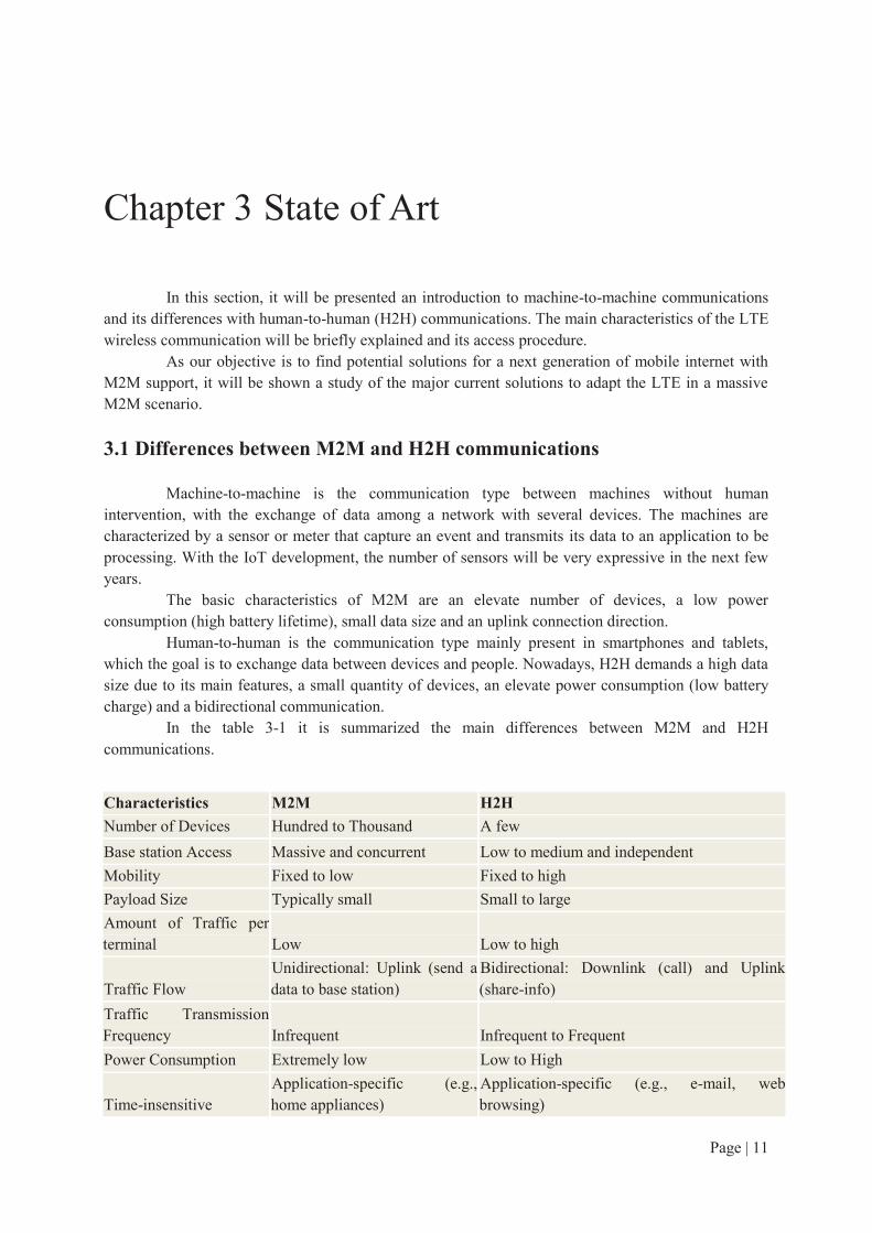
Machine-to-machine is the communication type between machines without human intervention, with the exchange of data among a network with several devices. The machines are characterized by a sensor or meter that capture an event and transmits its data to an application to be processing. With the IoT development, the number of sensors will be very expressive in the next few years.
The basic characteristics of M2M are an elevate number of devices, a low power consumption (high battery lifetime), small data size and an uplink connection direction.
Human-to-human is the communication type mainly present in smartphones and tablets, which the goal is to exchange data between devices and people. Nowadays, H2H demands a high data size due to its main features, a small quantity of devices, an elevate power consumption (low battery charge) and a bidirectional communication.
In the table 3-1 it is summarized the main differences between M2M and H2H communications.
Characteristics M2M H2H
Number of Devices Hundred to Thousand A few
Base station Access Massive and concurrent Low to medium and independent
Mobility Fixed to low Fixed to high
Payload Size Typically small Small to large
Amount of Traffic per terminal Low Low to high
Traffic Flow Unidirectional: Uplink (send a data to base station)
Bidirectional: Downlink (call) and Uplink (share-info)
Traffic Transmission Frequency Infrequent Infrequent to Frequent
Power Consumption Extremely low Low to High
Time-insensitive Application-specific (e.g., home appliances)
Application-specific (e.g., e-mail, web browsing)

Page | 12
Time-sensitive Application-specific (e.g., smart grid control data)
Application-specific (e.g., VoIP, online gaming)
Time-Controlled Application-specific (e.g., smart metering) No
Group Formation Yes (e.g., smart grid) No Table 3-1: Major differences between M2M and H2H communications, adapted from [1].
3.2 LTE description
In the current section, an introduction of the main features of LTE will be presented as well as a description of its physical layer and random access procedure.
3.2.1 General characteristics
Long Term Evolution is a standard for wireless network with a high-speed data. It is an evolution from the standard GSM/HSPA developed by the 3rd Generation Partnership Project (3GPP) and widely used for mobiles. The LTE brings more capacity and speed than its predecessors with a new radio interface.
LTE keeps the compatibility with the previous versions and uses a Multiple Input Multiple Output (MIMO), an Orthogonal Frequency Division Multiple Access (OFDMA) and a Single Carrier FDMA in the uplink.
3.2.2 LTE Physical Layer [14]
Some concepts of the LTE physical layer will be explained in this section to be a requirement for understanding the following sections.
The frame structure used in uplink channel is a time and frequency frame. In time, a frame represents 10 milliseconds, being composed by 10 subframes of 1
millisecond each. A subframe is composed by 2 slots, resulting in a 20 slots per frame. In frequency, a frame is delimited by the bandwidth. The LTE bandwidth defined in the
standard are 1.4, 3, 5, 10, 15, and 20 MHz. In this example, a 1.4 MHz frame is considered. The entire frame is divided in resource block, the smallest resources unit that can be allocated to an UE. It is a 180 kHz wide in frequency and 1 slot duration in time. For a 1.4 MHz frame, the number of resource block (RB) available is 6 x 20 = 120. A RB can be subdivided in 12 subcarriers of 15 kHz and 7 or 6 symbols that correspond to one slot. The figure 3-1 presents a frame and a resource block schematic.
Figure 3-1: Frame and Resource Block Schematic by [21]
The basic unit of time in LTE is called Ts and it is equal to 32.55 ns.

Page | 13
3.2.3 Random-Access Procedure in LTE [15][16]
Random access is an initial access procedure of connection to the LTE network. This procedure is a four message exchange protocol that connects a device to a base station, here knows as eNB (eNodeB or BS). The procedure uses the RACH (Random Access Channel) as transport-layer channel and the PRACH (Physical Random Access Channel) as the corresponding physical-layer channel. The PRACH is part of PUSCH (Physical Uplink Shared Channel).
It is important to note that in the LTE the RACH does not transport user data. The data will be transported for the PUSCH. In the LTE, the RACH is also used to synchronize the uplink time of each device with the base station.
The procedure can be divided in two groups: contention-based and contention-free. The first group has a contention mechanism when a collision is detected between two or more devices and this contention will manage the access in more steps. The second group has no contention mechanism, so the eNB will allocate a dedicated resource to UE, although it demands some connections situations.
Before starting the procedure, the eNB must broadcast to all devices in its cell coverage some parameters for initial connection. The eNB informs the available preambles for each group of devices that will be selected for the first message.
The procedure begins with each device choosing an available preamble. A preamble is a ZaddOff Chu Sequence and represents 64 different signatures. The different preamble configurations are showed in the table 3-2.
PRACH Configuration
Index
Preamble Format
System frame
number
Subframe number
PRACH Configuration
Index
Preamble Format
System frame
number
Subframe number
0 0 Even 1 32 2 Even 1
1 0 Even 4 33 2 Even 4
2 0 Even 7 34 2 Even 7
3 0 Any 1 35 2 Any 1
4 0 Any 4 36 2 Any 4
5 0 Any 7 37 2 Any 7
6 0 Any 1, 6 38 2 Any 1, 6
7 0 Any 2 ,7 39 2 Any 2 ,7
8 0 Any 3, 8 40 2 Any 3, 8
9 0 Any 1, 4, 7 41 2 Any 1, 4, 7
10 0 Any 2, 5, 8 42 2 Any 2, 5, 8
11 0 Any 3, 6, 9 43 2 Any 3, 6, 9
12 0 Any 0, 2, 4, 6, 8 44 2 Any 0, 2, 4, 6, 8
13 0 Any 1, 3, 5, 7, 9 45 2 Any 1, 3, 5, 7, 9
14 0 Any 0, 1, 2, 3, 4, 5, 6, 7, 8, 9
46 N/A N/A N/A
15 0 Even 9 47 2 Even 9
16 1 Even 1 48 3 Even 1
17 1 Even 4 49 3 Even 4
18 1 Even 7 50 3 Even 7
19 1 Any 1 51 3 Any 1
20 1 Any 4 52 3 Any 4
21 1 Any 7 53 3 Any 7
22 1 Any 1, 6 54 3 Any 1, 6
23 1 Any 2 ,7 55 3 Any 2 ,7
24 1 Any 3, 8 56 3 Any 3, 8
25 1 Any 1, 4, 7 57 3 Any 1, 4, 7
26 1 Any 2, 5, 8 58 3 Any 2, 5, 8
27 1 Any 3, 6, 9 59 3 Any 3, 6, 9
28 1 Any 0, 2, 4, 6, 8 60 N/A N/A N/A
29 1 Any 1, 3, 5, 7, 9 61 N/A N/A N/A
30 N/A N/A N/A 62 N/A N/A N/A
31 1 Even 9 63 3 Even 9
Table 3-2: PRACH Configuration by 3GPP TS36.211[15] - Table 5.7.1-2

Page | 14
Preamble Format
Total Length (in ms)
Number of Subframes
Guard Time (in ms)
Cell Radius
0 0.903 1 0.097 ~ 14 km 1 1.484 2 0.516 ~ 75 km 2 1.803 2 0.197 ~ 28 km 3 2.284 3 0.716 ~ 108 km
Table 3-3: Preamble Format Specifications by 3GPP TS36.211[15] Table 5.7.1-1.
As it is showed in the first table (3-2), there are four different preamble formats. In the second table (3-3), it is shown that each preamble format has its specific length in time that influence the number of consecutive subframe required to receive a preamble, not allowing some configuration index to be implemented, like 30, 46, 60, 61 and 62.
One preamble available is selected by the device and it sends the preamble sequence to the eNB corresponding subframe. The eNB detects the preamble in a specific subframe and prepares a response message called RAR (Random Access Response) with an ID, Random Access Radio Network Temporary Identifier (RA-RNTI). This ID contains the time-frequency slot, which the eNB detected the preamble. The message will be broadcast to all nodes in the cell coverage zone using the Physical Downlink Shared Channel (PDSCH).
The RAR has the detected preamble identity, an set of synchronization information, an information with the resource allocated by the eNB to the UE for message three, a backoff indicator that may be used in case of collision to delay the next random access attempt.
After sending a preamble, an UE has a time limited window to receive the RAR message from eNB to confirm a preamble reception. If an UE does not receive in time, the procedure must restart.
An UE that receive a RAR message can proceed to message three and send the random access message to its corresponding allocate resource. Normally, this message contains a RRC (Radio Resource Control) connection request. This message is sent on the PUSCH and uses the Hybrid Automatic Repeat reQuest (HARQ). HARQ controls the number of retransmissions allowed for the UE, in case of collision.
Message collision is a present factor in the RA procedure and can be detected in preamble message, when two or more UE send the same preamble in the same subframe. However, when these messages arrive at the same time, a constructive interference not allow the eNB to detect the collision, forcing the eNB to allocate resources for messages three and to broadcast the RAR. The RAR will be received for all UEs that have a no collision detected in the previous step and they will send the message three. All UE’s messages will collide in the same uplink time-frequency resources. A collision in an uplink resource causes signal interference that prevents a message to be decoded. In this case, a contention resolution must be applied. Some UEs will try a retransmission. Nevertheless, if one message is successfully decoded, then, the other messages will remain in the contention and a message four will be used to solve the contention.
The message four will inform an UE if its message was decoded or not. In an affirmative case, the random access procedure is completed. In a negative scenario, the UEs will exit the current random access procedure and start a new one. The figure 3-2 represents the random access procedure and its messages.

Page | 15
Figure 3-2: RA procedure by [21].
3.3 Random-Access Procedure Improvements
One of the main subjects of this project is to find some solutions to improve the random access performance in terms of access delay and success rate. Several recent works propose new techniques and solutions for the random access procedure in LTE, which some focus in the M2M scenario.
Among all papers studied, the key techniques and the promising solutions will be explained in the following paragraphs.
3.3.1 Basic Techniques
Earliest studies were made by 3GPP in [2] to investigate potentials improvements in the RA procedure. Some techniques were investigated to propose a solution for the large number of collisions in the RA procedure over a massive M2M scenario.
There are six techniques, originally studied by 3GPP, that are used in a significant number of papers as important elements for the new solutions.
Access Class Barring (EAB [2], Cooperative ACB [3]):
Access class barring (ACB) brings the idea of class of priority, where the devices are divided in groups and each group receives a parameter to access the network. In the Extended Access Barring (EAB), a control parameter is set with a value according to the network congestion state. The access to the network will be blocked only for the classes with a parameter value lesser than the control variable.
In a low congestion scenario, the control variable value is set low, and in a high network congestion scenario, the value is set high. The blockage allows the eNB to control the network overcharge. However, it strongly increases the access delay on the blocked devices.
A strategy proposed to decrease the access delay is the cooperative access class barring. This technique is suitable for the devices that are in cell coverage area of more than one base station (BS). In this scenario, one BS that detects a high congestion scenario sets its control parameter to a high value, blocking some devices classes. These devices can connect to another BS that presents a low congestion scenario and, therefore, it will set its control parameter to a low value. The advantage of this technique is the cooperation between base stations to reorganize the traffic flow.

Page | 16
Separation of resources [2]:
This technique presents a separation of preambles between H2H and M2M devices. The available preambles can be split into H2H and M2M subsets. It is also possible to allocate different RA slots to H2H and M2M devices.
Slotted Access [2]:
In the slotted access technique, dedicate RA slots are defined for each device.
Dynamic Allocation of Resources [2]:
Dynamic Allocation of Resources is one of the most interesting basic techniques. When the eNB detects a congestion scenario, it can decide to allocate additional RA slots. However, the additional resources will reduce the resources used for data transmission. The reducing of data resource is the reason of this technique cannot be considered a standalone solution. It must be a part of a global solution.
Backoff Adjustment Schemes [2]:
In case of collision, a backoff indicator is used to inform to the collided devices their next attempt time. One approach is to define different backoff timers for each device or for a group of devices, in order to delay the access attempt and decrease the network congestion.
Pull-based schemes [2]:
This schema requires a control of the network by the eNB that will decide the transmission time of each device. The eNB will inform to each device its access attempt starting time.
3.3.2 Promising Techniques
After studying several techniques, we have selected the nine most promising. We believe that these techniques can be a potential improvement to the random-access procedure. In figure 3-3, our objective is to show a schematic of the main techniques (in red) with the basic techniques (in blue) and main ideas (in purple) associated, following an example provided in [12].
Figure 3-3: RA improvements techniques schematic.
3.3.2-1 Self-Optimizing Overload Control
The technique presented in [1] provides an intelligent control loop that performs congestion monitoring, decision-making and PRACH resources adjusting according to the load condition. This

Page | 17
method uses a set of the most known techniques to improve the overload control in RA procedure as ACB, separation of resources, dynamic allocation, slotted-access scheme and also the p-persistent scheme.
The method implements an intelligent control loop that BS uses to collect information for overload monitoring, to make decisions and, then, to adjust PRACH resources. According to the congestion level, the eNB can vary the number of RA resources. If the number of RA resources reaches a maximum available limit, the base station temporarily restricts the access to the lowest priority M2M class using ACB.
There is only a theoretical work about this technique, although, in theory, it may have a good success rate because its smart allocation, which allows to eliminate congestion. It may be also capable of handling high traffic loads. However, in high traffic scenarios, the barring mechanism if used several times can make the method inefficient and can cause an increase of delay.
3.3.2-2 – Fast Adaptive Slotted-Aloha
Fast Adaptive Slotted-Aloha (FASA) is a technique proposed by [4] that collects access results in the past slots to apply them to track the network status. This method is only directed to event-driven applications.
An algorithm to track the network status must be deployed in the eNB. The use of drift analysis allows the eNB to estimate the transmission probability. The eNB collects information about the past state of the slots and analyzes the idles and collisions. After a drift analysis, the eNB will calculate the best slots to receive the next transmissions to increase the access probability. The probability will be used to select the best slots for the next transmission.
It was shown in the simulations that the eNB can converge to the final outcome quickly by being able to keep the track of number of backlogged devices more quickly. The results also show that the method can achieve a near-optimal performance in reducing the access delay. It also presents a robust performance under all traffic loads and it can achieve a high success rate.
The constraints of this technique may be the cost to eNB performs the track of the network status and the drift analysis and that this solution is dedicated to event-driven applications.
3.3.2-3 – Prioritized Random Access
Prioritized Random Access is a technique proposed by [5] that provides Quality of Service (QoS) for different classes of M2M devices. The solution uses two techniques: Virtual Resource Allocation and Dynamic Access Barring. The devices are divided in five classes of priority and each class has its own backoff exponent used to calculate a device backoff in case of retransmission. The method consists in to pre-allocating RACH resources for different M2M classes while prevents a large number of simultaneous RACH attempts.
In the Virtual Resource Allocation the eNB pre-assigns different amount of virtual resources for different M2M classes. In the figure 3-4, the resource allocation for the five classes is illustrated.

Page | 18
Figure 3-4: Virtual Resource Allocation [5].
In the Dynamic Class Barring, the eNB continuously monitors the loading state of the network in order to control the number of preamble transmissions on each RA slot. In the case of high traffic load, new arrivals from M2M devices are delayed until the conditions improve.
The results show a high performance in terms of success rate and average delay when compared with the results provided by 3GPP in [2]. It is a technique that respects QoS requirements although no information about energy-efficiency was provided. The use of barring algorithm can be a problem in high traffic situations.
3.3.2-4 – Overload M2M Femtocells
This is not a technique that can be directly applied to this project, but has important aspects to be commented. It provides a different approach with the use of a large quantity of femtocells instead the exclusive use of macrocells. The solution proposed by [6] presents a group-based (cluster) time control mechanism to solve the core network (CN) congestion problem in a femtocell-based M2M network.
With the substitution of some macrocells for several femtocells, the M2M devices can be categorized into macro or femto groups. It is dedicated to each group a granted time interval. In this interval, only M2M devices in the corresponding group can access the network. The access class barring is used to provide an access priority for each group.
This method can spread the traffic load of M2M devices over the time to reduce the traffic peak, and mitigate both CN and RA overload. The results show that it is possible to achieve a low delay by adjusting the femto and macro group size to an optimal value. This technique demands the deployment of femtocells structure at the cost of an improvement in the system capacity and in the indoor coverage. It is a low power and a low cost solution that also offers more mobility, although this solution is focused in CN congestion.
3.3.2-5 – Overload Synchronized M2M GERAN
This is a method proposed by [7] to handle to stationary M2M devices, which need periodic connection. A stationary device will skip the RA procedure by informing the eNB, during a previous connection, the next time(s) that it will need a connection.
This technique works with a certain group of devices and eliminates the necessity of a synchronization process after a first connection. In the figure 3-5, the solution behavior is illustrated. The eNB will automatically allocate resources for every device when the next transmission arrives. In the end of each connection, a device will inform the eNB its next connection time. An M2M device that requests a reservation from the network does not need to send a RA burst for the next connection. At the scheduled time, it simply starts waiting for a resource assignment.

Page | 19
Figure 3-5: Access Procedure [7]
This is a efficient solution for mitigating potential overload caused by synchronized M2M traffic. The eNB gets control over stationary devices connection times and it can schedule some connections slightly later to reduce the peak load. The results show a high success rate for periodic devices. Nevertheless, a technique that is suitable only for periodic devices can be considered a complete solution. It would be very interesting to use this technique along to others more complete. A precaution is necessary as this technique may not be compatible with other solutions.
3.3.2-6 – Self-Adaptive Contention
It is proposed by [8] a self-adaptive persistent contention scheme to schedule M2M devices in a periodical reporting manner. The method uses some basic techniques as EAB, separation of resources, dynamic allocation of resources, specifics backoff and pull-based schemes.
The process is made in two phases: contention and compact. In the contention phase groups of devices using the EAB are created and the M2M devices perform a RA procedure and set up a period to observe the successful contention count. The counter increases when an M2M device listens to a contention resolution and records the successful order until the RA succeed. The successful information is memorized by each device to be reused in a next attempt.
In the compact phase, the eNB will reduce the M2M PRACH resources to a minimum requirement when it detects that the network is stable. If the MTC PRACH has been changed, the devices will use the previous successful contention information to re-attach to the network, otherwise the eNB will calculate the previous successful information to adjust contention resources.
This technique shows a high success probability and in the compact phase, the contention becomes more efficient. Nonetheless, the access delay of the contention phase is longer than the standard scheme.
3.3.2-7 – Early Collision Detection
This is a new RA procedure that achieves a reasonable resource allocation. In [9], it is proposed a collision detection method in preamble message. If a collision is detected in message one the eNB will not need to schedule PUSCH resources to the collided preambles. The detection will use

Page | 20
a new kind of preamble that is composed by a preamble sequence followed by an UE identity information and CRC (Cyclic Redundancy Check).
A preamble collision creates an interference preventing the eNB to decode an UE ID. In this case, the eNB believes that a collision happened and, then, it will not schedule PUSCH resources for the message three.
This technique outperforms the traditional RA procedure in terms of successful accesses, resource efficiency and preamble collisions probability. It avoids resource wasting although there is no concern about QoS requirements.
It is a complicate question to change the preamble structure because the current preambles sequences are defined by the ZaddOff Chu sequences. The consequences caused by the changes in these sequences may be a problem to a real implementation of this technique.
3.3.2-8 – A Game Theoretic Approach
It was proposed by [10] a game theoretic algorithm implementation to solve the collision problem in LTE. The solution uses a resource separation method, dividing the resources in H2H exclusive, M2M exclusive and a hybrid space for both M2M and H2H. The algorithm uses the mixed strategy Nash Equilibrium of the game to allow the devices to compete for a RA opportunity. Nash equilibrium is a strategy profile that each player’s strategy is the best response to the others’ strategies.
In the algorithm each M2M device has three different actions: transmission using M2M resources, transmission using hybrid resources or keeping silent.
The results show that the technique has a great potential to be adaptive to a bursty LTE RACH traffic, although no access delay information is provided. The system throughput of M2M and H2H users are significantly guaranteed in a RACH overloaded scenario.
3.3.2-9 – Collision Resolution
This technique focuses in collision resolution unlike the vast majority of techniques that propose collision avoidance. A collision resolution algorithm based in splitting trees is proposed in [11]. In the algorithm, a collision scenario is considered and the devices that had collided will receive new opportunities until all collisions are solved.
This technique proposes a little change in the basic RA procedure, but without modifying the physical layer. It is created a new type of message four, called MSG 4b. The normal message four will continue to exist and the new message will only be sent to the collided devices. It will be used a Q-ary tree-splitting algorithm composed by q slots that can be expanded in other q slots if collision remains. In figure 3-6, it is shown a contention resolution scenario using the tree-splitting algorithm.
Figure 3-6: Split-tree Algorithm [11].
MSG 4b will notify the devices about the collision and will specify their next connection attempt. The recipients of MSG 4b will send a new MSGs 1, by transmitting a random preamble from
Page | 21
the set of q preambles in the designated Tree-splitting Random Access Opportunity (TRAO). In the example two users selected the preamble A, C and D. Those who selected the preamble C will receive the TRAO 2 and the others the TRAO 1. In the TRAO 1, there are one user for preamble C and one user for preamble D, so the contention for these both users is solved. However; there are two devices in preamble B, so a new MSG 4b will be sent to these devices to inform a new attempt in the TRAO 2 to them. In the TRAO 2 each preamble has a single device, and then the contention is solved. In case of more collisions the procedure will repeat until all contentions are resolved.
This method is a reliable and timely service for high numbers of synchronously accessing devices, while requiring fewer amounts of resources than others schemes. Simulation results show a negligible outage with an average of five preamble transmissions. However, the time spent in the collision resolution may not be suitable for delay-constraint devices.
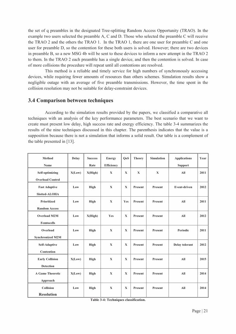
3.4 Comparison between techniques
According to the simulation results provided by the papers, we classified a comparative all techniques with an analysis of the key performance parameters. The best scenario that we want to create must present low delay, high success rate and energy efficiency. The table 3-4 summarizes the results of the nine techniques discussed in this chapter. The parenthesis indicates that the value is a supposition because there is not a simulation that informs a solid result. Our table is a complement of the table presented in [13].
Method Delay Success Energy QoS Theory Simulation Applications Year
Name Rate Efficiency Support
Self-optimizing X(Low) X(High) X X X X All 2011
Overload Control
Fast Adaptive Low High X X Present Present Event-driven 2012
Slotted-ALOHA
Prioritized Low High X Yes Present Present All 2011
Random Access
Overload M2M Low X(High) Yes X Present Present All 2012
Femtocells
Overload Low High X X Present Present Periodic 2011
Synchronized M2M
Self-Adaptive Low High X X Present Present Delay tolerant 2012
Contention
Early Collision X(Low) High X X Present Present All 2015
Detection
A Game Theoretic X(Low) High X X Present Present All 2014
Approach
Collision Low High X X Present Present All 2014
Resolution Table 3-4: Techniques classification.

Page | 22
As it is shown in the table, the most recent techniques are presents and only one does not have a theory or simulation work available. Only the Femtocells technique discussed the energy consumption as an improvement and only the Prioritized Random Access shows a concern about guaranteeing the QoS requirements. Some techniques are limited to a certain kind of application, as event-drive, periodic and delay tolerant applications.
We have different algorithms, some using a set of basic techniques and the others creating its own techniques, and, besides that, in general, we have important results in the key parameters with a low delay and a high success rate.

Page | 23
Chapter 4 Proposed Solutions
4.1 Main Ideas from Papers:
After studying several techniques, we have selected some ideas to elaborate a direction of improvements in the LTE RACH. These ideas are organized in three groups as follow:
Separation of resources:
· Separation of resource techniques can be defined based on different types of communication (M2M and H2H) or based on different groups of applications (critical, periodic, event-driven, energy-efficient).
· Priority classes can be useful to separate groups of devices and to allow a special handling to each class.
· Hybrid spaces for both M2M and H2H devices are a potential solution as it allows a more flexible mechanism to resources allocation according to the traffic type and congestion.
Methods to solve congestion under all traffic’s levels:
· The base station can evaluate the traffic and provide a corresponding response.
· A smart base station can control and adapt the contention mechanism based on network traffic conditions (diffusing new parameters set depending on the traffic, resources allocation and other conditions).
· A mechanism avoiding the waste of resources can identify the collision as soon as possible.
· A collision resolution method (Tree splitting approach) can be defined.
A based station that can calculate and inform the devices in a fast way the best slots to connect:
· FASA approach using prediction for the next access is a promising solution.
· Game theory approach using different access probabilities is interesting for a distributed approach.
4.2 Solution Algorithm
We will compose our work in two solutions.
4.2.1 Solution 1: Improve Preamble Capacity in a Group
We have decided to consider a technique that presents the separation of resources with priority classes and both M2M and H2H devices. We want different groups of devices, each one with similar QoS requirements. Each group can receive a certain level of priority by the eNB. It will be very important that, inside a group, each device can access the network with the same probability, despite the preamble selected. Hence, taking in account this situation, we have decided to focus our efforts in an improvement for the preamble message of RA procedure. We will verify the capacity of each preamble and possible solutions to reduce the number of collisions in message one, which will increase the success rate.

Page | 24
We can give a different selection probability for each preamble. This mechanism may be very useful to create priority classes. For example, in a certain group of low priority devices the preamble with smallest capacity will be selected and, on the other hand, in a group of high priority devices it will be selected the preamble with highest capacity. It is important that the base station has a control over the network to provide some chances according to the demand.
We can also provide a uniform probability of access to all devices in a group. In this situation, two devices, from the same group, that select different preambles will have the same probability of access. This is a very important contribution because allows the device to choose any preamble without any kind of restriction since the probability of success will be the same. The access probability can be adjusted according to the quantity of nodes or with the network congestion level. If the different capacities of each preamble are known, in overload scenarios it may be very interesting to keep a high probability of selection for the preamble with highest capacity.
4.2.2 Solution 2: Improvement in Preamble Reception Mechanism
While handling to the preamble message, we have noticed that the eNB can detect many preambles that arrive in the same subframe. However, this situation is considered a collision scenario in the standard LTE. Nonetheless, we have observed that some packets can be received in good conditions. Hence, we can answer to all these packets. We can also select a packet with a good value of SNR, but for this, we must implement a method to select a node that we consider anonymous since the preamble cannot carry any UE information. Today, it is impossible to differentiate a node from another one. If a method will created, we can provide the potential gain of this solution. We can discuss some hypothesis to differentiate the nodes such as considering the arrival time or the SNR level.
We believe that is very important that the eNB must be able to receive correctly a preamble. Even if there are more than one and they arrived in different times, we can propose a solution that we can decide which UE we want to give an access first. The preambles can arrive with different levels of SNR that provide information if a packet was received in good conditions, as some signals might not be detectable due to the propagation losses. In the LTE standard, the SNR level is not taken into account. If two packets arrive at the same time, a constructive interference will cause that both signals will overlap themselves and only one signal will be recognized by the BS.
We will elaborate an algorithm that considers both the arrival time and the SNR level to be able to decrease the collision amount. Some packets that normally have collided in the standard LTE will not collide in our approach, allowing us to provide a potential gain for our solution. The complete algorithm and its implementation will be explicated in the section 5.2 of the Chapter 5. The evaluation of the algorithm results and a discussion about new ideas for future works will be presented in Chapter 6.
4.3 Algorithm Conditions:
The algorithm idea was presented in the previous section, but it requires some conditions to work.
The changes in the collision detection mechanism will increase the number of devices that can transmit its message. However, if the remaining of RA procedure continues equal to the standard, the number of collided messages in the message three will increase. When the algorithm was proposed, an initial idea was to modify the entire procedure. However, we decide to focus our efforts in providing some mechanism to improve the first message, which does not have a lot of propositions in the literature.
Other conditions can be summarized as follow:

Page | 25
· We will consider a scenario with an orthogonal interference among the packets.
· To evaluating the access with message one we suppose a guaranteed timeslot with probability of success equal to 1 for data.
· A network will be deployed in an area of 250m of radius and a BS will be placed in the center.
· There will be only one BS.
· The UEs and the BS are perfectly synchronized.
· The UEs know the available preambles.
· Antennas will be oriented in a way that it will be considered omnidirectional.
· Only one antenna will be used by the BS.
· We assume that the PRACH will be a continuous period in the simulation. We assume the configuration for an LTE scenario of two works: the European Project
5GNOW [18] and a studied made by Nokia [19]. The first provides simulation scenarios that will be used. The second one provides more information that will be discussed in the next section.
Nokia Study:
The enterprise Nokia has made a study for a future product, which is described as Nokia LTE M2M. We selected some ideas from this study and also some configuration parameters. These parameters will be discussed in the Chapter 5.
The study shows new features proposed by the release 13 from 3GPP. An important characteristic of M2M devices is its low energy consumption, so it is proposed the a 1.4 MHz bandwidth with an uplink and a downlink peak rate at 200 kpbs.
Considering that the LTE can have a bandwidth of 20 MHz, it is proposed the division of a 20 MHz band in subbands. Each subband will be processed as an independent channel with 1.4 MHz of bandwidth. So, it will be created a total of 14 independent channels.

Page | 26
Chapter 5 WSNet and LTE solutions
5.1 WSNet Description
5.1.1 The Simulator
WSNet is an event-driven simulator for wireless networks on a large scale developed at the CITI laboratory. It is written in C and it is configured using XML files. This simulator is able to manage a massive number of nodes. It has a complete and modular model for the software architecture of nodes, i.e. the different layers of the OSI model.
WSNet makes discrete events simulation, which principle is that the system fits its behavior only to the appearance of events in time. This kind of simulation can save up a great deal of intermediate calculations, to focus only on the critical moments of the simulation.
WSNet possesses a modular structure illustrated in figure 5-1, where the main blocks are described: the radio medium, the simulation core and the nodes.
The radio medium consists of three sub-blocks: propagation, interference and modulation. The simulator core has a scheduler that generates and processes the events and the packets of the simulation. A node is a set of layers, which communicate directly among them by the functions TX and RX. Each layer corresponds a particular model, which is written and compiled in C.
Figure 5-1: WSNet Architecture Schematic.
Figure 2: Node architecture. The modules that compose the platform can be compiled inside or outside the kernel. The
modules presents are: application, energy, fading, global map, interface, interferences, intermodulation, mac, map, mobility, modulations, monitor, noise, pathloss, physical, routing, sensor, shadowing and transceiver. It is not necessary all modules to build the platform.
In the xml files used to configure the platform, the global architecture is described presenting all modules that will compose the platform. Each module configures its parameters. The simulation parameters are set in this file, like number of nodes and simulation time. Also, it is possible to associate each node created to different architectures. An example of an xml file will be provided in the appendixes.

Page | 27
5.1.2 Packets and Modules
In WSNet, communication between nodes on the network is made via packets. It is created in the application layer by an UE node and is sent to a mac layer. The packet is transmitted to the lower layers thanks to the TX function. From the MAC layer the packet is sent to the physical layer that is modeled using radio and antenna modules as well as a medium module. The RX, TX, and MEDIA_RX MEDIA_TX functions allow the exchange of packets between the different modules. In the medium, the packet power is calculated and includes the antenna gain in transmission, the pathloss, the fading the shadowing and the antenna gain in reception. The packet noise, SNR and PER are also calculated.
After the medium the packet is sent to the interface of reception and then to the reception transceiver followed by the mac layer. In the end, it is received in the application layer of the BS.
When a module wishes to send a packet to a lower module, it calls the TX function that automatically calls the tx function of the lower layer. When a module wishes to send a packet to the upper module, it calls the function RX automatically calling the rx function of the upper layer. A schematic of one module is present in the figure 5-2
Figure 5-2: WSNet Module.
5.2 LTE Solutions
In this section, it will be presented all models created in this project. Only the algorithm will be described and in the next chapter a validation for each model will be showed.
5.2.1 Modification in Simulator Kernel
The WSNet is a packet-oriented simulator and to be used in our experiences it must be adapted to a model compatible with an LTE approach with massive accesses. Some changes in the kernel of the simulator were made to achieve a suitable model for LTE.
The standard kernel has a mechanism to duplicate a packet received by the medium to be sent to all nodes in the network. In a scenario with several nodes, the packet duplication will influence the simulator performance, causing a memory overcharge and a slow simulation. The LTE model only requires packet duplication to a base station. The adaptation made in the kernel was an addition of an option called “No packet duplication” in the medium mechanism. When this option is set, the duplication will be only available to the base station. A node parameter was used to verify if a selected node is an UE or a BS.
5.2.2 LTE Application
An M2M application was made to create a scenario with one BS and N-1 UEs. Each one will have different behaviors. Only one node will be set as a BS and its role in the application level is to

Page | 28
receive the packets sent from UE nodes. The base station position was set in the center of a circle with 250m of radius.
The UE nodes have a more complex role. Each node will be placed randomly inside an area with a random antenna orientation. All UE will create a packet. Each packet will select a random time to begin its first transmission. The xml configuration file informs a value of period to transmission. The number of transmissions for each UE is defined as the total simulation time divided by the period value. During one period, all UEs must select its random transmission time.
5.2.3 Propagation Model and Antennas
The pathloss and the shadowing models were created to simulate an LTE propagation model. The shadowing of LTE was implemented as log-normal shadowing model with a standard deviation of 8 dB.
Pathloss
The pathloss model specifications were provided in [17]. There are two different kinds of pathloss: LOS (line-of-sight) and NLOS (non-line-of-sight). The used model will be defined by a probability calculation. The formulas are defined for a range of 500m as follow, where “r” is the distance BS-UE in kilometers.
PL !"(r) = 103.4 + 24.2 # log$%(r) + 20&[dB]
PL !"#(r) = 131.1 + 42.8 $ log%&(r) + 20'[dB] Prob!"#(r) = min*0.018r , 1- $ /1 5 e 67&.&9:; + e 67&.&9:
Prob !"#(r) = 1 5 Prob!"#(r)
The algorithm will generate a random probability, for each packet, that will be compared with Prob!"#(r) to define which model will be considered.
Antenna
An LTE antenna model was created to calculate the antenna gain in transmission (gain_tx) and in reception (gain_rx). The model provided by [18] uses a horizontal pattern, calculated as follow:
A<(>) '= '5min ?12 * >>:@C-
D , AEF dB, where >:@C = 70 degrees, AE = 25 dB and > is the angle. Both use the same formula, but the angles have different orientation. The algorithm must
provide an efficient calculation of the angle between the reference antenna and the opposite device (UE for gain_rx and BS for gain_tx).
An omnidirectional model was also made, where both gains are equal to 0.
5.2.4 Transceiver LTE
The LTE radio must provide the functions of reception, transmission, carrier-sensing (a pre-reception step), radio energy control, radio state manage and radio options set. A radio has five states: idle, sleep, rx, rxing and tx.
A state machine for both UE and BS are shown in the figure 5.3:

Page | 29
Figure 5-3: Radio State Machine.
It was defined that the UE will keep the IDLE state until a packet becomes ready to be transmitted and the BS will keep the RX state to wait for a packet.
In the transmission state, a packet is sent to the medium and in the reception state, a packet is received from the interface.
The LTE radio specifications were provided by two studies made by NOKIA[19] and Neul-Huawei[20]. The first one provided information about radio modulation and minimum sensibility, and the second one about radio state energy consumption. As discussed in the previous chapter, the bandwidth chosen for each channel is 1.4 MHz, and all the parameters respect this configuration.
The parameters chosen for the transceiver are the following:
· Modulation: BPSK.
· Minimum sensibility: -138 dBm.
· Maximum Power BS: 46 dBm, provided by 3GPP.
· Maximum Power UE: 23 dBm, provided by NOKIA.
· Radio IDLE energy consumption: 5 uA, provided by Neul-Huawei.
· Radio SLEEP energy consumption: 5 uA, provided by Neul-Huawei.
· Radio TX energy consumption: 190 mA, provided by Neul-Huawei.
· Radio RX energy consumption: 20 mA, provided by Neul-Huawei.
· Radio RXING energy consumption: 20 mA, provided by Neul-Huawei. With the provided parameters, a value of noise was calculated to guarantee the
corresponding value of sensitivity and an acceptable SNR level. The noise found was -145.3dBm The modulation used was BPSK, and with that information, it is possible to calculate the
value of Symbol Period. There are 30.72 Msymbols in one second and the transmission rate desired is 200 kbps. This
means 153 symbols for each bit. The biggest packet is a preamble type 3 with 27744 symbols. This packet corresponds to 23 bytes, which is the packet maximum size. As the normal Ts value is 30.72 symbols/us it is necessary a conversion to work in the simulator. The Ts in nanoseconds is calculated as follow:
Ts = 153 symbols
30.72 symbols
us
= 5000 ns
The UE transceiver will use only the transmission functions and the BS transceiver will use the reception and carrier-sensing functions.
Page | 30
Transceiver Multiband for Base Station
The basic model of LTE transceiver was presented, but it will be used exclusively by the UE nodes. The BS needs some increments in the LTE transceiver. A multiband transceiver model will be implemented to the BS, using logical channels.
We have decided to use a logical channel because in the simulator if two packets select the same physical channel, a model of interference will be applied, even if they have selected different preambles. However, the interference model among preambles cannot be the same interference model among channels, and to prevent big changes in the simulator structure, we have decided that each preamble will transmit in an independent logical channel.
With one logic channel for each preamble, the transceiver must allow several receptions at the same time or subframe, in the project context. A selected solution was the creation of a multiband transceiver in reception that can handle to different preamble indexes and different physical channels. With fourteen physical channels and each one supporting sixty-four preamble, the new transceiver will handle, in a maximum scenario, with 896 logical channels. A logical channel can be implemented as a normal structure of the transceiver with its own parameters. An additional structure will be used to store an array of them.
Collision Detection Mechanism
The collision detection algorithm in message one is very important in our project. It was developed as a different approach in comparison with the standard.
In a traditional situation, a collision is detected when two or more packets arrive in the same slot in different times. If all of them arrive at the same time the collision will be detected in the message three, instead of message one, making the BS sends the message two. This approach considers only the arrival time.
Our approach uses the same principle of arrival time of the standard approach with the SNR level. If two packets arrive at the same time we have a constructive collision and no collision will be detected in message one, leaving the detection to message three. However, when two or more packets arrive with different arrival times and different SNR levels, some can be receive in good conditions (good SNR levels), and others in bad conditions (bad SNR levels) will be rejected. The SNR level will be used to estimate the PER level in the implementation.
In a scenario with more than two packets, if all packets arrive at the same time, they will be accepted because the eNB cannot detect the collision with the preamble message. If we have more than two packets that have a satisfactory condition, we will accept only the first of them that arrives, rejecting all the others.
Our algorithm allows a better identification of collisions case and using signal power it is possible to improve the reception. Our algorithm creates new scenarios for packet acceptance, increasing the quantity of packets received by BS. We will be able to estimate the potential gain of the packet selection in comparison with the standard approach, where the packet cannot be selected.
The transceiver reception is made in two steps. The first one is the carrier-sensing and the second is the reception itself. The algorithm consists in filtering the packets in the carrier-sensing to select the packets that must be received in the reception step. However, at the time that the filter is running, there is no information about the SNR/PER of the packets. The only information available is the packet arrival time. The filter cannot cover all cases, as the PER is also an important parameter to filter the packets.
In the developed algorithm we keep the filter in the carrier-sensing and we retrieve the packets missed by the previous filter in the reception. The arrival time is the parameter used to filter. When the first packet arrives, a control parameter will receive its arrival time and its ID will be added in a list of packets to be used in the reception step. When the next packet arrives, its arrival time will

Page | 31
be compared to the control parameter. If the time is the same, the packet ID will be added to the reception list. However, if the time is different, the list will be cleaned. The next packets will arrive with a higher arrival time and the list will continue empty.
This first step can cover the case when all packets have the same arrival time and no SNR information is considered. However, the packets rejected when there was at least one with different arrival time may have a good SNR and a low PER. This is the main reason to add a mechanism in the reception step. When it starts, if the list is empty, the first packet with low PER will be added to the list. All packets in the list will be sent to the upper layers.
5.2.5 MAC
The preamble selection happens in this layer. The MAC model has a transmission function where the message one of RA procedure is implemented and a reception function where the packets that had not collided are received.
The message one algorithm consists in three steps: preamble and channel selection, subframe calculation and packet transmission.
Preamble selection
A preamble structure was created with the follow parameters: preamble index, message type, subframes and SFN (subframe number). This structure is indexed by the preamble number. Each packet can receive a random structure or a pre-configured structure. Two parameters were created in the xml configuration file. The first one controls if the preamble selection will be randomly or if the preamble will take the value defined by the second parameter.
Besides the preamble receives a random value, an additional case, used in the finals simulations, was created. The preamble selection can be randomly between the six different groups of preambles or a probabilistic selection between these six groups, where each group has a different probability to be selected.
The maximum number of preamble and channels are defined directly in the function. The channel number will be the channel quantity multiplied by the preamble quantity plus the preamble index selected. This will give the logic channel number, comprised between 0 and 895 (14 physical channels X 64 preamble index).
Subframe calculation
The transmission time selected for each node in the application layer will be used to calculate the slot to transmit the packet in the MAC layer, according to the preamble selected. The preamble selected gives the information about the subframes that it can transmit. An algorithm is used to calculate the next subframe for each device. The current time is used to verify the subframe of packet creation. With this information, it is possible to calculate in which subframe the device must transmit. The simulation time starts at 0. If the packet is not in the beginning of the correct subframe, it must select the next one. The SFN also impact in which subframe will be selected, even or odd.
Packet transmission
The packet received from the application layer is useful to define the time when the MAC layer has to launch the RACH procedure. The new packet created in the previous step has the information about the preamble and the starter time to transmit. A packet header is created to save the packet size information, used to estimate the packet extension in time. It is important to keep the 23 bytes as it was set in the LTE transceiver.
The packet is linked to an event in the scheduler and it will be transmitted when the event starts.
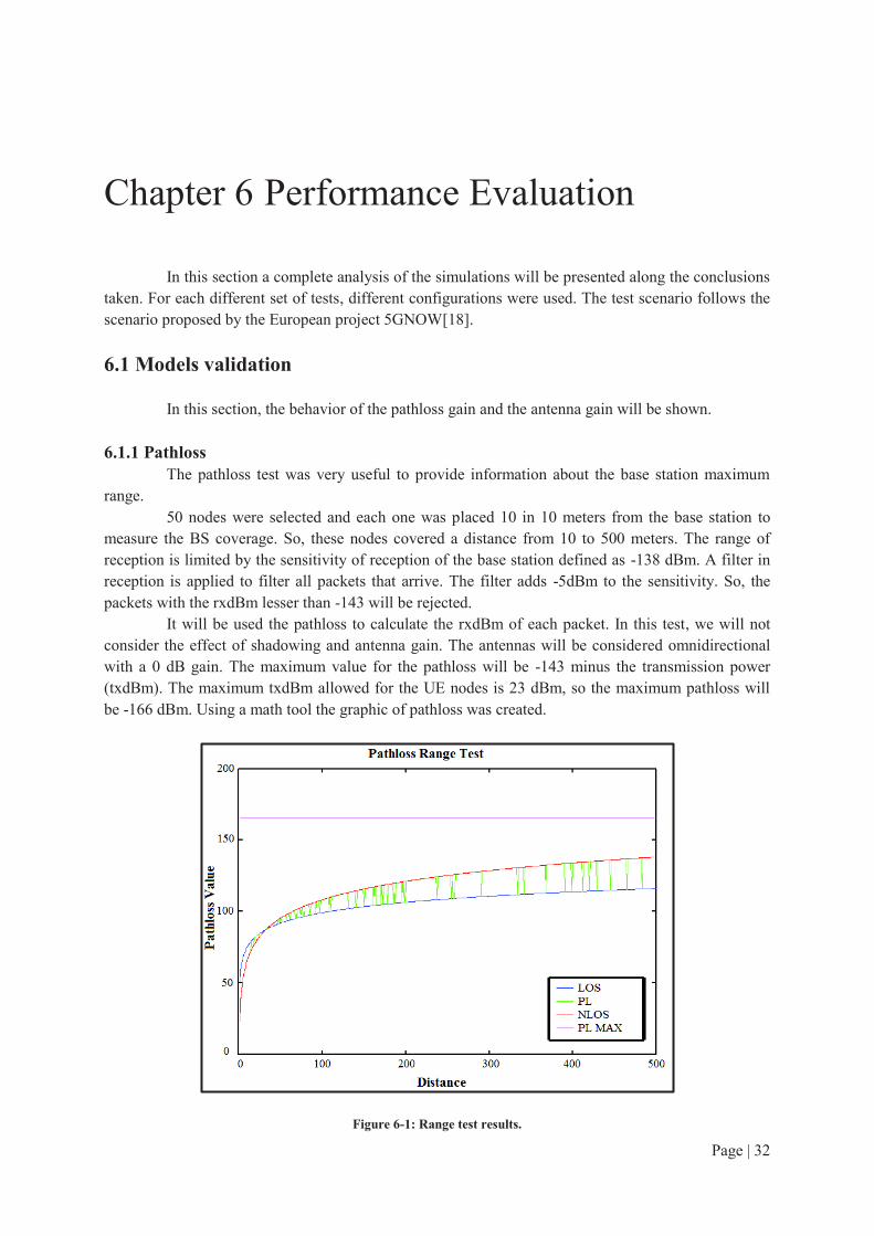
Page | 32
Chapter 6 Performance Evaluation In this section a complete analysis of the simulations will be presented along the conclusions
taken. For each different set of tests, different configurations were used. The test scenario follows the scenario proposed by the European project 5GNOW[18].
6.1 Models validation
In this section, the behavior of the pathloss gain and the antenna gain will be shown.
6.1.1 Pathloss
The pathloss test was very useful to provide information about the base station maximum range.
50 nodes were selected and each one was placed 10 in 10 meters from the base station to measure the BS coverage. So, these nodes covered a distance from 10 to 500 meters. The range of reception is limited by the sensitivity of reception of the base station defined as -138 dBm. A filter in reception is applied to filter all packets that arrive. The filter adds -5dBm to the sensitivity. So, the packets with the rxdBm lesser than -143 will be rejected.
It will be used the pathloss to calculate the rxdBm of each packet. In this test, we will not consider the effect of shadowing and antenna gain. The antennas will be considered omnidirectional with a 0 dB gain. The maximum value for the pathloss will be -143 minus the transmission power (txdBm). The maximum txdBm allowed for the UE nodes is 23 dBm, so the maximum pathloss will be -166 dBm. Using a math tool the graphic of pathloss was created.
Figure 6-1: Range test results.
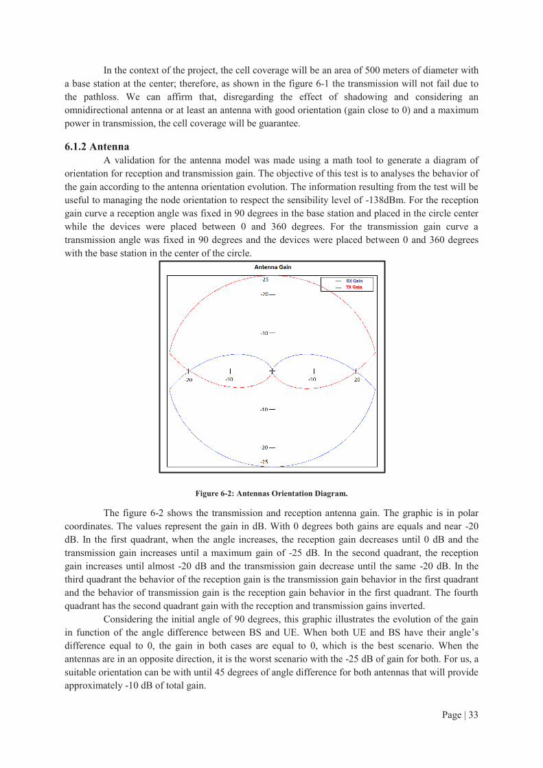
Page | 33
In the context of the project, the cell coverage will be an area of 500 meters of diameter with a base station at the center; therefore, as shown in the figure 6-1 the transmission will not fail due to the pathloss. We can affirm that, disregarding the effect of shadowing and considering an omnidirectional antenna or at least an antenna with good orientation (gain close to 0) and a maximum power in transmission, the cell coverage will be guarantee.
6.1.2 Antenna
A validation for the antenna model was made using a math tool to generate a diagram of orientation for reception and transmission gain. The objective of this test is to analyses the behavior of the gain according to the antenna orientation evolution. The information resulting from the test will be useful to managing the node orientation to respect the sensibility level of -138dBm. For the reception gain curve a reception angle was fixed in 90 degrees in the base station and placed in the circle center while the devices were placed between 0 and 360 degrees. For the transmission gain curve a transmission angle was fixed in 90 degrees and the devices were placed between 0 and 360 degrees with the base station in the center of the circle.
Figure 6-2: Antennas Orientation Diagram.
The figure 6-2 shows the transmission and reception antenna gain. The graphic is in polar coordinates. The values represent the gain in dB. With 0 degrees both gains are equals and near -20 dB. In the first quadrant, when the angle increases, the reception gain decreases until 0 dB and the transmission gain increases until a maximum gain of -25 dB. In the second quadrant, the reception gain increases until almost -20 dB and the transmission gain decrease until the same -20 dB. In the third quadrant the behavior of the reception gain is the transmission gain behavior in the first quadrant and the behavior of transmission gain is the reception gain behavior in the first quadrant. The fourth quadrant has the second quadrant gain with the reception and transmission gains inverted.
Considering the initial angle of 90 degrees, this graphic illustrates the evolution of the gain in function of the angle difference between BS and UE. When both UE and BS have their angle’s difference equal to 0, the gain in both cases are equal to 0, which is the best scenario. When the antennas are in an opposite direction, it is the worst scenario with the -25 dB of gain for both. For us, a suitable orientation can be with until 45 degrees of angle difference for both antennas that will provide approximately -10 dB of total gain.

Page | 34
6.2 Preamble Capacity
There are 64 preambles index divided in four groups. We will consider for our tests only the first group. Among the 16 preambles, we will select only 6. Each one has a different capacity of subframes. The test scenario is shown above:
Test scenario:
· Channel Quantity: 1.
· Preamble Index: 0, 3, 6, 9, 12, 14.
· Period (seconds): 10, 60, 300.
· Nodes: 100, 250, 500, 750, 1000, 2500, 5000, 7500, 10000, 25000, 50000.
· Simulations: 100 for each scenario.
· Simulation time: Period x Number of Simulations. Architecture:
· Propagation Model: LTE Pathloss + Shadowing.
· Antenna BS: LTE Omnidirectional.
· Antenna UE: LTE Omnidirectional.
· Transceiver UE: Transceiver LTE.
· Transceiver BS: Transceiver LTE Multiband. The test objective is to identify the maximum capacity of each preamble using the new
algorithm of collision detection in message one. The results will also present the preamble capacity using the standard algorithm of collision detection (true collision). The graphics represent the average results for all three different periods.
Figure 6-3: Preamble 0 Transmission Success vs Number of UEs.
0
0,2
0,4
0,6
0,8
1
0 10000 20000 30000 40000 50000
Preamble 0 Capacity % success 10
% success 60
% success 300
True % of
success 10
True % of
success 60
True % of
success 300

Page | 35
Figure 6-4: Preamble 3 Transmission Success vs Number of UEs.
Figure 6-5: Preamble 6 Transmission Success vs Number of UEs.
Figure 6-6: Preamble 9 Transmission Success vs Number of UEs.
0
0,1
0,2
0,3
0,4
0,5
0,6
0,7
0,8
0,9
1
0 10000 20000 30000 40000 50000
Preamble 3 Capacity % success 10
% success 60
% success 300
True % of
success 10
True % of
success 60
True % of
success 300
0
0,2
0,4
0,6
0,8
1
0 10000 20000 30000 40000 50000
Preamble 6 Capacity % success 10
% success 60
% success 300
True % of
success 10
True % of
success 60
True % of
success 300
0
0,1
0,2
0,3
0,4
0,5
0,6
0,7
0,8
0,9
1
0 10000 20000 30000 40000 50000
Preamble 9 Capacity % success 10
% success 60
% success 300
True % of
success 10
True % of
success 60
True % of
success 300

Page | 36
Figure 6-7: Preamble 12 Transmission Success vs Number of UEs.
Figure 6-8: Preamble 14 Transmission Success vs Number of UEs.
In all graphics presented above (figure 6-3 to 6-8), we observe that the period value has a big influence in the transmission success; higher the period, more nodes can transmit inside each period without collide.
The test made helps us to verify the capacity of each preamble. Clearly visible, the preamble 0 has the worst capacity and arrives quickly to a saturated state. The preamble 14 has the best performance, saturating only with a very large quantity of nodes. The theoretical limit of each preamble can be calculated to validate the simulation results. The preamble 0 can transmit one time for each two frames, which means, one opportunity every 20 milliseconds. Thus, it has 500 opportunities for second. The preambles 3, 6, 9, 12 and 14 have 1000, 2000, 3000, 5000 and 10000 opportunities per second respectively.
An analysis of the gain between both collision detection algorithms can be made. In all the cases, we observe an important gain in performance, in many cases 20%, for our algorithm. Knowing all preambles capacity, it is possible to elaborate some strategies to take advantage of the different configurations to give a priority for the highest capacity preambles, as an example.
0
0,1
0,2
0,3
0,4
0,5
0,6
0,7
0,8
0,9
1
0 10000 20000 30000 40000 50000
Preamble 12 Capacity % success 10
% success 60
% success 300
True % of
success 10True % of
success 60True % of
success 300
0
0,1
0,2
0,3
0,4
0,5
0,6
0,7
0,8
0,9
1
0 10000 20000 30000 40000 50000
Preamble 14 Capacity % success 10
% success 60
% success 300
True % of
success 10
True % of
success 60
True % of
success 300

Page | 37
We can take an example from the preamble 6 graphic in figure 6-5. If we want a 60% of success rate with a 300 second period, we have a limit around 25000 nodes for the standard approach. However, we have around 50000 nodes for the same success rate with our solution. It is a 100% of gain in terms of devices. Considering our approach, we can use twice the number of nodes to achieve the same success rate. Now, if we consider 10000 nodes with a 60 seconds period, we have a success rate of 40% for the standard approach and 60% for our solution. The difference of 20% represents that we have a gain of 2000 devices that were successfully received.
Regarding all the previous graphics, we can guarantee a certain probability in function of the number of UEs. Considering only the preambles 0, 9 and 14 and a period of 300 seconds, to be able to guarantee 90% of success rate we can have a maximum of 2500, 15000 and 50000 UEs respectively. If we want a 50% of success rate with a period of 60 seconds we can have a maximum of 3500, 20000 and more than 50000 UEs, respectively. The BS can take advantage of the capacity information to manage a probability of access for each preamble with the idea to keep a certain level of success for each preamble access.
6.3 Random Preamble selection vs selection with probability
In a normal scenario, each device can select one random preamble, so in this condition the probability to select one from 6 preambles is 1/6. However, this scenario may cause a big problem when the number of devices grows, because the preambles with lower capacity will start to saturated and the number of collisions will also increase.
Our proposed solution is to give a different selection probability to each preamble. This probability will be in function of the average capacity. The capacity and the probability of each one is shown below:
· Preamble 0: 1 subframe available every 2 frames, probability 1/43.
· Preamble 3: 2 subframes available every 2 frames, probability 2/43.
· Preamble 6: 4 subframes available every 2 frames, probability 4/43.
· Preamble 9: 6 subframes available every 2 frames, probability 6/43.
· Preamble 12: 10 subframes available every 2 frames, probability 10/43.
· Preamble 14: 20 subframes available every 2 frames, probability 20/43. The test scenario is identical to the previous scenario. It is present in the graphic the true
value of both approaches, which represents the success transmission considering the normal collision detection algorithm instead the proposed algorithm.

Page | 38
Figure 6-9: Success Transmission vs Number of UEs for a 10 seconds period.
Figure 6-10: Success Transmission vs Number of UEs for a 60 seconds period.
Figure 6-11: Success Transmission vs Number of UEs for a 300 seconds period.

Page | 39
6.3.1 Solution 1 Analysis
Regarding the graphics 6-9, 6-10 and 6-11, we can identify the efficiency provided by the probabilistic distribution solution, in comparison with the traditional random approach. In the 10 seconds period simulation the gain is about 10% for a large quantity of nodes. However, when the number of UEs surpasses 30000, in the true collision case, the success rate of the random approach becomes higher than the probabilistic approach.
In the random selection approach, the transmission is equally distributed among each preamble. Increasing the number of nodes, the lower index preamble will be the first to saturate, as they have the smaller capacity. The saturation for the preamble 0 begins with 500 nodes, but for the preamble 14 it begins with 10000 nodes.
In the probabilistic approach, each preamble capacity is considered in the selection. However, with a large number of nodes all preambles will saturate together. So the result observed in the graphic 6.9 shows that with more than 30000 nodes all preambles become saturated and we have a large number of collisions. In the first approach, the preamble 14 was not totally saturated, so there are a few transmissions without collision.
For the 60 seconds graphic the gain becomes almost 20% between the two approaches. For the third graphic we have a success rate higher than 90% for both probabilistic distribution scenarios, giving almost a 10% gain over the normal case. In these two graphics, considering the number of UE, the same situation observed in the previous example does not happen. However, the situation will happen as the number of UE becomes very large, around 200000 nodes for the 60s period and 1000000 nodes for the 300s period.
We can evaluate the potential gain of our solution 1, alone, in the graphic 6-11. Considering 50000 nodes with the true collision curves, we have 82% success rate for the standard case and 92% for the algorithm. This 10% of difference represents a gain of 5000 devices that were successfully received by eNB. If we select a 94% of success rate, 15000 nodes in the standard approach will be considered, while in our solution 35000. It represents a 133% of gain in terms of devices, so with our solution we can use 20000 more devices to achieve the same success rate that the standard approach.
We have designed the use of probability to guarantee a certain access probability of success for each preamble. One scenario that we can consider is that the each device selects a random preamble. With our algorithm, this selection will not influence in the transmission performance because all preambles will have the same access probability guaranteed. We can define a function to provide a success rate desired for each device, according of the quantity of nodes. For example, to provide a success rate of 90% for all preambles, we must consider a maximum of 2500, 15000 and 50000 UEs for the preambles 0, 9 and 14, respectively with a 300 seconds period.
We can proceed to two ideas to handle with the threshold scenario. The first one is to only use our solution when under the threshold. However, if we want a technique more efficient, our second idea is to concentrate the saturation over the lower capacity preamble and keep a minimum of success in some preambles with higher capacity, after the threshold. This technique will be discussed in the final section, 6.4.1.
6.3.2 Solution 2 Analysis
In all the graphics we can notice the important contribution of our method of preamble selection. We can achieve a 20% gain in the first two graphics (figure 6-9 and 6-10) and a 10% gain in the last graphic (figure 6-11). The gain is also present if we consider both solutions.
From the graphic in figure 6.10 we can discuss the potential gain of both solutions. Considering the two curves with probabilistic distribution we want a 90% of success rate, so we have a number of nodes close to 10000 for the standard approach. However, in our solution we have 20000 nodes for the same 90% of success rate. It is a 100% of gain in terms of nodes. So, with our approach

Page | 40
we can use twice the number of nodes to achieve the same success rate. Now, if we consider 20000 nodes, we have a success rate of 80% for the standard approach and 90% for our solution. The difference of 10% represents that we have a gain of 2000 devices that were successfully received.
6.4 Leads for future works:
We evaluate the performance of message one with these tests. However, it is important to remember that we made some hypotheses to validate these tests. For the next studies, we must consider a mechanism to improve the message two in order to avail these project ideas, creating an option for the future of the M2M in LTE. Increasing the number of transmissions success in message one creates a difficult to inform only the correct UE to send a message three. In a scenario where two devices transmit in the same subframe with different times and only the first one with a good SNR has success, the current message two will be sent to both devices, causing a collision in message three.
In the next few lines, we discuss some strategies that can be considered possible solutions or improvements in the messages two. We also present some new ideas as improvements for the message one.
6.4.1 Solution 1 Strategies
Dynamic Preamble Probability
In a scenario with hundreds of thousands devices, collisions are inevitable. However, to increase the number of success transmissions an option is to concentrate the collisions over the preambles with lower capacity, releasing the preambles with higher capacity to transmit with less collisions. The BS has the role to detect a scenario of saturation for the preambles with high capacity and then adjusts the probability of all preambles. The preambles with lower capacity will be its selection probability increased and the preambles with higher capacity will be its selection probability decreased.
We have discussed in the previous sections a capacity for the preambles 0, 9 and 14 under a scenario of 90% success rate. In the case, which the number of devices is bigger than the capacity measured for a certain probability, we can adjust the number of devices for each preamble. For example, if we have more than 50000 devices with preamble 14, we will decrease the selection probability for the preamble 14 to guarantee a maximum of 50000 UEs. In this scenario, we need to increase the probability for the other preambles, reducing their success rates, but we preserve the desired success rate for the preamble with high capacity.
A mechanism like that does not avoid collisions, but concentrate them in one side to improve the performance in the other side, allowing an increase of success transmissions.
6.4.2 Solution 2 Strategies
Subframe Division: a Message 1 Improvement
A potential solution to increase the performance of the message one is to divide a subframe in some blocks. A subframe has 1 millisecond of length; however a packet length is about 0.91 milliseconds. This difference, around 90 microseconds, can be used to create different groups, which each one of them represents a different packet arrival time inside the subframe. The 90 us difference can be divided, for example, in 9 groups with 10 us of difference between the start of each one. The first group starts in the beginning of the subframe and the second one 10 us after.
Only one group will transmit. The packet sent in the first group will have higher priority than the others. Our idea is that each group represents a priority. In case of more than one preamble in the same subframe, only the preamble with lower group will transmit. The group selection will be made

Page | 41
along with the preamble selection by the UE. Nonetheless, to inform only the correct UE, an improvement in the message two must be made.
Message two improvements without Multipath effects
The message two must inform to only the devices that have transmitted without collision due to interference constructive or bad SNR. In the current standard, message two will inform to all devices that have sent a preamble in a certain subframe to transmit the message three. As our algorithm increases the number of successful messages one it also increases the number of collisions in message three.
We need to elaborate a possible solution to limit the message two destinations. The preamble that arrives in BS has some information about its power, SNR and arrival time. A hypothesis that the signal power necessary to send a response message for the node that has a good SNR is approximately equal to the power used by the node to send the message one to the BS. This is a hypothesis of the no effect of multipath, which both messages will travel the same path and then suffer the same effects of pathloss, shadowing and antenna gain. Assuming this hypothesis, the eNB need to know the initial power of each device. Having all the information, the eNB can estimate the distance of each device and, then, adjusts its transmission power to send the message two to the correct device. The eNB will program a maximum range of transmission that will comprise the zone where the device is placed.
If the BS has not sufficient information or the hypothesis was not respected, it is possible to estimate a zone with a certain probability that the device is there. In the worst case, more than one device will collide in the message three. The eNB can propose a mechanism of mapping the cell to identify possible zones and then associate a probability for each one. In this case, the first transmissions will help the eNB to elaborate this mapping to take advantage from the fact that M2M devices have no mobility, although the first devices will continue to collide in message three.
We do not consider any information addition in the preamble structure because the eNB cannot decode the preamble as it is a ZaddOff Chu sequence.

Page | 42
Chapter 7 Conclusion Following the current trends of smart cities, scenarios with thousands of connected devices
are actually present in our days and its growing will continue in the next years. Considering the LTE, the network solution adopted in this project, our objective was to propose solutions for a massive M2M traffic scenario using the random access procedure of LTE. Initially, a survey of the most promising techniques was made to provide some ideas to our new technique to solve the access procedure collisions. Several interesting techniques have been proposed along the last five years presenting collision avoidance methods and collision resolution methods. Particularly, the separation of resources for specific groups of devices has become an important starting point to our approach.
We have decided to concentrate our efforts in the two solutions that use separation of resources method and the first message of the random access procedure, the preamble message. The first technique presents a preamble capacity measurement that allows us to estimate the quantity of nodes supported by each preamble. Knowing this information, the base station can provide selection probability for the different preambles. The mainly objective is to deliver to each node, which is inside a group of devices with same characteristics and priority, a uniform success rate in the access procedure. Analyzing the results of the first technique, we have concluded that, in providing a uniform distribution, the technique has a significant gain, until a threshold, where the number of collisions of our solution becomes higher than the number of collisions of the standard approach. Desiring a scenario compatible with our two solutions, we have proposed some ideas of possible improvements in the access procedure. A solution to the threshold found the first solution is to dynamically adapt the selection probabilities, guaranteeing a certain success rate for the preambles with higher capacity while concentrate the collision to the preambles with lesser capacity.
Our second solution was proposed as an improvement of the collision detection mechanism for the base station. In the current mechanism a collision is detected if two or more devices arrive in different moments. In opposite to this scenario, we want that preambles that were received with satisfactory conditions can continue in the access procedure. Our solution stresses the fact that we can make better use of the preambles received in a subframe, reducing the number of collision situations. Regarding the results of the second solution, we have evaluated the potential gain of our solution over the standard collision detection mechanism. Besides the current constraints for the implementation of our solution, its impact in the number of collisions is very expressive. To improve the second solution we need to adapt the message two, in order to eliminate the collisions that will occur in the message three caused by our solution. We suggest a mechanism that can calculate the approximately distance of each device to limit the response messages to them. Another idea is similar to the second solution, as it also presents some changes in the collision detection mechanism, and both can be used together. We can subdivide the subframe in some groups, according to the arrival time, and provide a priority for each one. The devices will select a group, but only one group will transmit at a time.

Page | 43
Bibliography Main Techniques References:
[1] A. Lo, Y. Law, M. Jacobsson, and M. Kucharzak, “Enhanced LTE-Advanced Random-Access Mechanism for Massive Machine-to-Machine (M2M) Communications,” in Proc. 27th
Meeting of Wireless World Research Form (WWRF), Oct. 2011. [2] 3GPP TR 37.868 V11.0, Study on RAN Improvements for Machine-type Communications, October 2011 [3] S.-Y. Lien, T.-H. Liau, C.-Y. Kao, and K.-C. Chen, “Cooperative access class barring for
machine-to-machine communications,” Wireless Communications, IEEE Transactions on,
january 2012. [4] Wu et al., “Fast Adaptive S-ALOHA Scheme for EventDriven Machine-to-Machine Communications,” IEEE VTC-Fall, Sept. 2012, pp. 1–5 [5] J.-P. Cheng, C. han Lee, and T.-M. Lin, “Prioritized Random Access with dynamic access barring for RAN overload in 3GPP LTE-A networks,” in 2011 IEEE GLOBECOM Workshops
(GC Wkshps), Dec. 2011, pp. 368–372. [6] A.-H. Tsai et al., “Overload Control for Machine Type Communications with Femto
Cells,” IEEE VTC-Fall, Sept. 2012, pp. 1–5. [7] R. Paiva et al., “Overload Control Method for Synchronized MTC Traffic in GERAN,”
IEEE VTC-Fall, Sept. 2011, pp. 1–5. [8] S.-T. Sheu et al., “Self-Adaptive Persistent Contention Scheme for Scheduling Based Machine Type Communications in LTE System,” Int’l. Conf. Selected Topics in Mobile and
Wireless Networking, July 2012, pp. 77–82. [9] Zhang, N. ; Kang, G. ; Wang, J. ; Guo, Y. ; Labeau, F., “Resource Allocation in a New
Random Access for M2M Communications,” Communications Letters, IEEE (Volume:PP , Issue: 99 ), Mars 2015. [10] Yuan-Chi Pang ; Shih-Lung Chao ; Guan-Yu Lin ; Hung-Yu Wei “Network Access for
M2M/H2H Hybrid Systems: A Game Theoretic Approach,” Communications Letters,
IEEE (Volume:18 , Issue: 5 ), 2014, pp 845-848. [11] Madueno, G.C. ; Stefanovic, S. ; Popovski, P. ; “Efficient LTE Access with Collision
Resolution for Massive M2M Communications”, in Globecom Workshops (GC Wkshps), Dec.
2014, pp. 1433-1438.
Survey References:
[12] A. Laya, L. Alonso, and J. Alonso-Zarate, "Is the Random Access Channel of LTE and LTE-A Suitable for M2M Communications? A Survey of Alternatives," Communications Surveys & Tutorials, IEEE, vol. 16, pp. 4-16, 2014. [13] Islam, M.; Taha, A.-E. ; Akl, S. , “A Survey of Access Management Techniques in
Machine Type Communications,” Communications Magazine, IEEE (Volume:52 , Issue: 4 ), April 2014, pp. 74 – 81.

Page | 44
3rd
Generation Partnership Project Technical Specifications:
[14] TS 36.211 V12.5.0 Physical channels and modulation (Release 12), March 2015. [15] TS 36.213 V12.5.0 Physical layer procedures (Release 12), March 2015. [16] TS 36.321 V12.5.0 Medium Access Control (MAC) protocol specification (Release 12), March 2015. [17] TS 36.814 V9.0.0 Further advancements for E-UTRA physical layer aspects (Release 9), March 2010.
European Project 5GNOW website:
[18] www.5gnow.eu
Whitepapers
[19] Nokia Whitepaper: Nokia LTE M2M, Optimizing LTE for the Internet of Things. [20] Neul and Huawei Whitepaper from Cambridge Wireless Website: Introduction to “Clean-Slate” Cellular IoT radio access solution.
Image References:
[21] 4g-lte-world.blogspot.fr/2013/04/random-access-procedure-rach-in-lte.html

Page | 45
Appendixes An example of an xml file is provided below: <?xml version='1.0' encoding='UTF-8'?> <worldsens xmlns="http://worldsens.citi.insa-lyon.fr"> <!-- == Classes =================================================== --> <!-- mediums classes --> <pathloss class="pathloss"> <c> <param key="library" value="pathloss_LTE"/> </c> </pathloss> <shadowing class="shadowing"> <c> <param key="library" value="shadowing_LTE"/> </c> </shadowing> <fading class="fading"> <c> <param key="library" value="fading_none"/> </c> </fading> <interferences class="interferences"> <c> <param key="library" value="interferences_orthogonal"/> </c> </interferences> <intermodulation class="intermodulation"> <c> <param key="library" value="intermodulation_none"/> </c> </intermodulation> <noise class="noise"> <c>
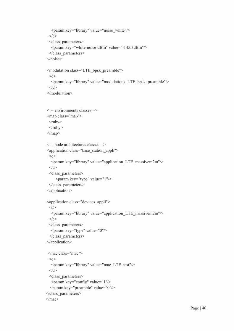
Page | 46
<param key="library" value="noise_white"/> </c> <class_parameters> <param key="white-noise-dBm" value="-145.3dBm"/> </class_parameters> </noise> <modulation class="LTE_bpsk_preamble"> <c> <param key="library" value="modulations_LTE_bpsk_preamble"/> </c> </modulation> <!-- environments classes --> <map class="map"> <ruby> </ruby> </map> <!-- node architectures classes --> <application class="base_station_appli"> <c> <param key="library" value="application_LTE_massivem2m"/> </c> <class_parameters> <param key="type" value="1"/> </class_parameters> </application> <application class="devices_appli"> <c> <param key="library" value="application_LTE_massivem2m"/> </c> <class_parameters> <param key="type" value="0"/> </class_parameters> </application> <mac class="mac"> <c> <param key="library" value="mac_LTE_test"/> </c> <class_parameters> <param key="config" value="1"/> <param key="preamble" value="0"/> </class_parameters> </mac>

Page | 47
<transceiver class="radio_ue"> <c> <param key="library" value="transceiver_LTE"/> </c> <class_parameters> <param key="modulation" value="LTE_bpsk_preamble"/> </class_parameters> </transceiver> <transceiver class="radio_bs"> <c> <param key="library" value="transceiver_LTE_multiband"/> </c> <class_parameters> <param key="modulation" value="LTE_bpsk_preamble"/> </class_parameters> </transceiver> <mobility class="mobility"> <c> <param key="library" value="mobility_static"/> </c> </mobility> <interface class="antenna"> <c> <param key="library" value="antenna_LTE"/> </c> </interface> <!-- simulation classes --> <global_map class="global_map"> <c> <param key="library" value="global_map_basic"/> </c> <class_parameters> <param key="x" value="500"/> <param key="y" value="500"/> <param key="z" value="0"/> </class_parameters> </global_map> <monitor class="birth_mon"> <c> <param key="library" value="monitor_dummy_monitor"/> </c> </monitor>

Page | 48
<!--== Mediums ================================================= --> <medium name="air"> <pathloss name="pathloss"> </pathloss> <shadowing name="shadowing"> </shadowing> <fading name="fading"> </fading> <interferences name="interferences"> </interferences> <intermodulation name="intermodulation"> </intermodulation> <noise name="noise"> </noise> <modulation name="LTE_bpsk_preamble"> </modulation> </medium> <!--==Environments ============================================= --> <environment name="outdoor"> <map name="map"> </map> </environment> <!--==Node Architectures============================================ --> <!-- == Base Station == --> <node_architecture name="base_station_node" birth="0" default="false"> <implementation> <application name="base_station_appli"> <down name="mac"/> <parameters> <param key="type" value="0"/> </parameters> </application>

Page | 49
<mac name="mac"> <up name="base_station_appli"/> <down name="radio_bs"/> </mac> <transceiver name="radio_bs"> <up name="mac"/> <down name="antenna"/> <parameters> <param key="nodetype" value="0"/> <param key="modulation" value="modulation"/> <param key="dBm" value="46"/> </parameters> </transceiver> <interface name="antenna"> <up name="radio_bs"/> <parameters> <param key="medium" value="air"/> </parameters> </interface> </implementation> <mobility name="mobility"> </mobility> </node_architecture> <!-- == Devices == --> <node_architecture name="devices_node" birth="0" default="true"> <implementation> <application name="devices_appli"> <down name="mac"/> <parameters> <param key="type" value="1"/> <param key="period" value="10s"/> </parameters> </application> <mac name="mac"> <up name="devices_appli"/> <down name="radio_ue"/> </mac> <transceiver name="radio_ue"> <up name="mac"/>

Page | 50
<down name="antenna"/> <parameters> <param key="nodetype" value="1"/> <param key="modulation" value="modulation"/> <param key="dBm" value="23"/> </parameters> </transceiver> <interface name="antenna"> <up name="radio_ue"/> <parameters> <param key="medium" value="air"/> </parameters> </interface> </implementation> <mobility name="mobility"> </mobility> </node_architecture> <!--==Simulation============================================== --> <simulation nodes="101" duration="1000s"> <global_map name="global_map"> </global_map> <monitor name="birth_mon"> </monitor> <node id="0" architecture="base_station_node"> </node> </simulation> </worldsens>

Page | 51
Abstract A large number of connected devices are widely present in cities and industries. This number
continues to grow and a wireless network solution to connect all of them is necessary. The current LTE is a natural choice to handle to the massive M2M scenario. Nevertheless, the LTE random access procedure must be adapted to support the large traffics because in its current state, the number of collisions in the random access procedure saturates the network, causing a low performance. The project started with a survey of the current techniques that introduce some improvements to the random access procedure to solve the collision problem. The most interesting are the separation of resources, the use of prioritized classes of devices, the collision resolution solution and the hybrid resources for both human and machine communications. Considering these techniques, two contributions focusing on the preamble message of the random access procedure have been proposed. The first contribution analyzes the preamble capacity and provides a selection probability that guarantee a uniform success rate independent of the preamble chosen. The second contribution evaluated the potential gain if, a different method to detect preamble collisions considering the arrival time and the SNR level, is defined. The WSNet simulator has been adapted to an LTE massive context and the random access procedure has been partially implemented. For the first contribution, the results showed that under a threshold (number of users) the success rate is higher than the standard approach. A proposition to extend this contribution is proposed in future works. The second contribution presents an important gain over the standard solution. This shows the importance to define new strategies preamble detection. Some ideas were also proposed with this objective such as discrimination based on the arrival time or voluntarily creation of offsets.
Un large nombre de dispositifs connectés sont déployés dans les villes et l’industrie. Ce
nombre continue à croître et une solution de réseau sans fil pour les interconnecter est nécessaire. Le LTE actuel est le choix naturel pour gérer l’accès massif de M2Ms. Néanmoins, la procédure d'accès aléatoire LTE doit être adaptée pour soutenir les grands trafics, car dans son état actuel, le nombre de collisions dans la procédure d'accès aléatoire sature le réseau, provoquant une faible performance. Le projet démarra par une étude bibliographique sur les techniques qui améliorent la procédure d'accès aléatoire et résolvent les problèmes de collision. Les plus intéressantes sont la séparation des ressources, l'utilisation de classes de priorité pour les dispositifs, la solution de résolution de collision et les ressources hybrides pour des communications humaines et machines. Compte tenu de ces techniques, deux contributions centrées sur le message préambule de la procédure d'accès aléatoire ont été proposées. La première contribution a analysé la capacité du préambule et une probabilité de sélection a été mise en place afin de garantir un taux de succès uniforme indépendamment du préambule choisi. La seconde contribution propose d’évaluer le gain potentiel d’une méthode différente pour détecter les collisions de préambule, compte tenu du temps d'arrivée et du niveau de SNR. Le simulateur de WSNet a été adapté au contexte massif LTE et la procédure d'accès aléatoire a été partiellement mise en œuvre. Pour la première contribution, les résultats ont montré que sous un certain seuil (nombre d’utilisateurs) le taux de succès de cette technique est plus élevé que l'approche standard. Une extension de cette solution pour gérer la situation au-dessous d'un seuil a donc été proposée. La deuxième contribution présente un gain important sur la solution standard et montre l’importance de définir de nouvelles stratégies de détection de préambule. Quelques idées ont donc également été proposées comme la discrimination en fonction du temps d'arrivée ou de créer volontairement des décalages.