accessible bus stop design guidance - transport for...
TRANSCRIPT

ACCESSIBLEBUS STOP DESIGN GUIDANCE
REVISED EDITION 2017
MAYOR OF LONDON

02 Accessible Bus Stop Design Guidance Contents
The Accessible Bus Stop Design Guidance sets out requirements and guidance for the design of accessible bus stop environments. It should be used by those who shape the environment through planning and street design as well as engineers designing bus-specific infrastructure.
This document forms one part of Transport for London’s Streetscape Toolkit, and should be read in conjunction with other TfL guidance documents:• Streetscape Guidance• London Pedestrian Design Guidance• London Cycling Design Standards• Kerbside Loading Guidance• Station Public Realm Urban Design Guidance
Published by Transport for London, 2017
Contents
1 Introduction............................................ 04
2 Accessible bus services........................... 10
3 Bus stop location.................................... 14
4 Passenger waiting area............................. 19
5 Bus stop area.......................................... 25
6 Bus stop layouts..................................... 27
7 Bus boarders........................................... 30
8 Bus bays.................................................. 34
9 Kerb profiles and heights......................... 36
10 Cycle facilities......................................... 38
11 Other considerations.............................. 43
12 References/data sources and Appendix... 46

03 Accessible Bus Stop Design Guidance Figures
Figures
Figure 1 Street Types for London.......................... 07
Figure 2 Features of the bus stop environment............................................ 08
Figure 3 Passenger groups benefiting from low-floor buses....................................... 11
Figure 4 Bus stop layout objectives....................... 12
Figure 5 Relationship between buses and kerbs.... 13
Figure 6 Considerations for bus stop locations..... 15
Figure 7 Bus arrival patterns.................................. 16
Figure 8 Centre of path layout............................... 21
Figure 9 Back to kerb layout.................................. 21
Figure 10 Back of path layout.................................. 21
Figure 11 Boarding and alighting zones.................... 22
Figure 12 Kerbside approach with parking on approach and exit.................................... 28
Figure 13 Exit side of pedestrian crossing............... 29
Figure 14 Exit side of junction................................ 29
Figure 15 Full-width boarder................................... 31
Figure 16 Alternative full-width boarder layouts..... 31
Figure 17 Multiple bus full-width boarder............... 31
Figure 18 Half-width boarder.................................. 32
Figure 19 Amended bus bay................................... 35
Figure 20 Filled-in bus bay with parking/loading...... 35
Figure 21 Half-filled bus bay................................... 35
Figure 22 Mandatory cycle lane at bus stop........... 39
Figure 23 Indicative bus stop bypass layout........... 41

04 Accessible Bus Stop Design Guidance Introduction
This chapter provides an introduction to the guidance and a summary of the key requirements to achieve an ‘Accessible bus stop’.
1. Introduction
BUS
STOP
BUS
STOP

05 Accessible Bus Stop Design Guidance
1. INTRODUCTION
Every day in London 1.3 million journeys are made by customers with disabilities, 700,000 journeys are made by people aged over 75, nearly five million journeys are made by passengers carrying heavy luggage and 1.5 million by people with small children. Ensuring that the London bus network continues to be accessible for all Londoners, is critical for London’s future economic prosperity and social cohesion.
There are many different user groups who have different needs with regard to bus stop design. Specific user groups that need special consideration include those customers that use a wheelchair, have limited mobility, are blind or visually impaired, are hearing impaired, have learning difficulties and the elderly. It is also important that designers consider these different user needs such as those who use wheelchairs, crutches, walking sticks, canes, guide dogs, mobility scooters, shopping trolleys, and buggies accessing bus services.
This guide updates the ‘Accessible Bus Stop Guidance note BP1/06’ published in January 2006 and its predecessor documents. These updated guidelines have been developed in the context of the Equality Act 2010, the Mayor’s Transport Strategy and the Accessibility Implementation Plan.
This intention of this guidance is to help encourage all those involved in the design,
construction and operation of London’s roads to consider the different accessibility needs of Londoners who use the TfL bus network. The importance of an accessible bus service will increase as the number of older and disabled Londoners is projected to rise significantly.
This document updates the original accessibility guidance to ensure it is both relevant and reflects changes in policy. Key additions include:
Introduction
• Revised criteria for an accessible bus stop
• New chapters on interaction of bus stops with other street facilities (‘cycle facilities’ and ‘other considerations’)
Key omissions include:
• Removal of references to articulated buses and particular kerb types that are not specified for use by TfL

06 Accessible Bus Stop Design Guidance Introduction
Accessible bus stopsThis guidance, aims to provide all those involved in the construction of bus stops with design guidance that ensures bus stops are accessible to all, particularly disabled passengers. This guidance will also assist highway authorities in the development of practical and affordable measures to improve accessibility at bus stops that are compatible with the particular characteristics of low-floor buses deployed on London’s road network.
The introduction of low-floor buses fitted with ramps for wheelchair access throughout London, has led to a requirement for appropriate kerbside access at bus stops. Unless all stops along a bus route are equally accessible, passengers may be unable to board or alight a bus at their desired location and the potential benefits from low-floor buses will be reduced. This hinders the public transport network being fully inclusive.
The Equalities Act (2010) places a duty on both public transport operators and highway authorities to provide reasonable adjustments so that disabled passengers are not disadvantaged. Providing access between a low-floor bus (fitted with ramps) and the footway, is crucial to fulfilling these duties. It is also important to consider the needs of other disabled groups such as blind or cognitive impaired bus passengers, as well as those carrying heavy luggage and pushchairs.
From an operational perspective, a well designed bus stop can provide significant benefits. Bus
stop design and location is recognised as a key element in the drive to improve the quality of bus services for all users.
It is important to view the bus stop as an interchange, rather than simply a location along a bus route where buses stop, comprising only a post with a flag and a cage laid on the road surface. Bus passengers are also pedestrians at each end of the bus trip and all elements of their journey should be considered including the convenience and comfort of the waiting environment.
Street Types for London frameworkThe Street Types for London framework has been developed in recent years in collaboration with London’s boroughs. It takes account of local and network priorities and aims to help the consistent allocation of road space across London. The aim is to ensure consistency in approach in considering the operation and function of different streets.
For all Street Types accessible bus stop facilities should be provided, however Street Types may influence the different levels of service and capacity will be required at bus stops.
A designer can highlight where specific schemes have been successful in encouraging better behaviour or more efficient use of space and assess whether a similar approach may be sensible for a location with a matching Street Types. This translation of Street Types into a specific response should help identify where people should expect to find similar types of infrastructure or levels of service across London.
Ultimately, the Street Types framework provides a unified view of London’s roads. Within this framework, the individual design elements which cumulatively influence the bus stop environment can be considered for each location, as illustrated in figure 1.
The Street Types framework indicates how the relative significance of movement and place influences the suitability of a particular design and expectations for the level of provision required. As such, Street Types provide an overarching context to discuss the suitability of applying the design tools defined within this note.

07 Accessible Bus Stop Design Guidance Introduction
Place
Mov
emen
t
Strategic significance
Stra
tegi
c si
gnifi
canc
eLo
cal s
igni
fican
ce
Local significance
eg Core road
M3P1
M3P2
M3P3
M2P1
M2P2
M2P3
M1P1
M1P2
M1P3
eg High road
eg High street eg City street
eg Town square
eg City hub
eg Connector
eg Local street eg City place
Figure 1: Street Types for London
07 Accessible Bus Stop Design Guidance

08 Accessible Bus Stop Design Guidance
• Security (including lighting)• Bus stop post and flag• Surface markings for buses• Bus passenger shelter and seating• Utilities access• Information (including timetables
and maps)• Drainage• Pedestrian footway• Height and type of kerb• Adequacy of waiting area• Space for bus to straighten• Approach and exit paths for buses• Connectivity with footway• Convenience for passengers
Introduction
Figure 2: Features of the bus stop environmentFigure 1 shows how each Street Type is assigned a Movement and Place value between 1 and 3; the higher the number the more strategic the importance of the Movement or Place function. Accessibility of bus stops needs to be considered in all of these locations, although the assigned Street Type can help to inform how the bus stop will interact with the surrounding footway and carriageway.
Bus stop environmentWhen reviewing individual bus stops, and their immediate environment, designers need to take account of the wide range of issues that are discussed within this guidance and that each site is a unique location, with unique bus stop environment characteristics (see figure 2).
Healthy StreetsHealthy Streets aim to reduce traffic, pollution and noise, create more attractive, accessible and people-friendly streets where everybody can enjoy spending time and being physically active, and ultimately to improve people’s health. Providing an accessible bus network will be a key part in achieving this ambition across London.
The bus network has a critical contribution in improving the health of Londoners, increasing physical activity and providing access to vital amenities. More accessible bus stops enhance these benefits by providing more inclusive bus services, and so reducing social isolation and increasing the number who can use these services.
The objective is to ensure that bus stops have a fully accessible design, by using features such as kerbside controls and bus boarders as design tools. Additionally, it is important for:
• Local authorities to remove obstacles around bus stops as footway clearance is a criteria required for accessibility at bus stops
• Planners and engineers to optimise the location, design and construction of bus stops
• Motorists and enforcement authorities to recognise the necessity for bus stops to be kept clear of parked vehicles
• Bus driver training to include how to approach and correctly use the bus stop; particularly when deploying the ramp for a wheelchair
Bus stop environment

09 Accessible Bus Stop Design Guidance Introduction
Bus stop accessibilityA key TfL objective is to increase the number of accessible bus stops. 95% of all bus stops in London will be accessible by March 2017.A bus stop must meet the following criteria to be fully compliant as an accessible bus stop:• Clearway in place – On borough roads a clearway
is denoted by a thick solid yellow line (Traffic Signs Regulations and General Directions (TSRGD) 1025.1), each bus stop should have one of these along the length of the bus stop cage. This, in conjunction with the relevant upright sign (TSRGD Schedule 7, Part 6, Clause 1), allows for the enforcement of the no stopping restrictions
The requirement for timeplates has now been removed for roads on the Transport for London Road Network (TLRN) because the double red line at bus stop denotes no stopping
• Kerb >100mm – In order for a bus to deploy its ramp safely the ideal range in terms of kerb height is 125-140 millimetres, however 100 millimetres is the minimum for it to be compliant
• Access free of impediments – A visual check of the area around the bus stop, including the surrounding pavement be undertaken, to ensure that the bus will be able to deploy its ramp so that wheelchair users and people with prams can access the ramp. This is important in preventing visually impaired people walking into obstacles when boarding and alighting the bus

10 Accessible Bus Stop Design Guidance Accessible bus services
This chapter provides an overview of how London’s bus services are accessible. It also sets out objectives of the bus stop layout in the design of a bus stop.
2. Accessible bus services

11 Accessible Bus Stop Design Guidance Accessible bus services
2. ACCESSIBLE BUS SERVICES
Low-floor bus usersLow-floor buses reduce the height differential between the kerb and bus floor, improving accessibility for all passengers. Mobility impaired passengers, including wheelchair users, benefit most from low-floor buses. When designing bus stops for low floor bus access, the needs of all passengers should be considered.
Research conducted by Transport Research Laboratory (TRL Report 271) has shown that passengers with pushchairs also benefit greatly from the introduction of low-floor buses. A list
of bus user groups that benefit from low floor buses is shown in figure 3.
Features of London bus servicesThe entire TfL bus network is operated using low-floor vehicles. All London buses have a single step entry, a low-floor in the front part of the vehicle, and either a sloping gangway or a step towards the rear over the drive axle. Most buses in London have front doors for boarding passengers and centre doors for those alighting. It should be noted that the New Bus for London (Routemaster) has three doors, all of which are used for boarding and alighting. This includes a central door to allow easy access for mobility passengers. Powered ramps are usually fitted to the centre door where
wheelchair users may board and alight. Push buttons are provided for wheelchair users to alert the driver when the ramp needs to be deployed.
Additionally, low-floor buses are provided with the means of lowering, or ‘kneeling’, the bus suspension to reduce the step height at stops. This is provided at the passenger’s request. The ‘Big Red Book’, a guidance manual provided to all London Buses’ drivers, states that the bus should pull up as near as possible to the kerb. Drivers are also guided to ‘kneel’ the bus if a passenger asks or if the driver observes a passenger requiring this facility.
Figure 3: Passenger groups benefiting from low-floor buses
11 Accessible Bus Stop Design Guidance
Older PeoplePassengers with shopping
or luggage
Wheelchair users
Visually impaired people
People with pushchairs
People with young
children
Low-floor bus access benefits

12 Accessible Bus Stop Design Guidance Accessible bus services
Bus stop layout objectivesThe objectives of an ideal bus stop layout are shown in figure 4. The bus should stop parallel to, and as close to, the kerb as possible to allow effective use of the bus’ facilities. The critical dimensions to consider are the vertical height, or step height, from the kerb to the bus floor and the horizontal gap from the kerb edge to the side of the bus. A well-designed bus stop will provide features which co-ordinate with the facilities of the low-floor bus and minimise vertical height and horizontal gap distances.
Figure 4: Bus stop layout objectives
12 Accessible Bus Stop Design Guidance
• Allow easy unobstructed access to and from the stop
• Remove street furniture which prevents passengers boarding and alighting
• Affordable and commensurate with accessibility benefit
• Minimise use of kerb space where there are competing demands for frontage access
• Allow the bus to line up within 200mm of and parallel with the kerb
• Prevent/dissuade other vehicles from parking in the stop areas
• Minimise time spent at the bus stop by the bus
Bus stop layout objectives

13 Accessible Bus Stop Design Guidance Accessible bus services13 Accessible Bus Stop Design Guidance
Figure 5: Relationship between buses and kerbsKerb heightsAs well as considering the bus stop layout for accessibility of the stop, it is important to consider the design and height of the kerb to enable the bus ramp to be deployed safely. The size of the vertical gap between the kerb and floor of the bus will affect the gradient of the ramp when it is deployed. If this gradient is too severe some wheelchair users may be unable to enter or exit safely from the bus. TfL require buses to be capable of deploying a ramp, giving a 1:8 or 12% gradient onto a kerb range of 100mm-140mm. This is in order to comply with the duties required under the Equality Act 2010, to provide reasonable adjustments so that disabled people are not disadvantaged. This regulation, therefore, assumes a ‘standard’ kerb height of 140mm, which, although not the case universally, is the height that vehicle manufacturers are guided to apply in bus design.
Best practice is a kerb height between 125mm and 140mm, as the ramp cannot be deployed if the kerb is too low or too high. The minimum height for bus stop to be classified by TfL as accessible is 100mm, whilst kerb heights above 150mm are not recommended.
Figure 5 shows the relationship between the bus and kerb. It is important to recognise that, when deployed on a 100mm-140mm high kerb, the gradient of the ramp may vary. The major determinants include the:
Reduction fromoriginal step height
New step height
Kerb
5.4: ‘Kneeling’ step height
Road level
Bus floor
Stepheight
Kerb
5.3: Normal step height
Road level
Bus floor
Ramp gradient
Kerb
Ramp
5.2: Ramp gradient
Road level
Bus floor
Kerbheight
Verticalgap
Kerb
5.1: Critical dimensions
Road level
Bus floor
Horizontalgap
• Type of ramp
• Ramp length
• Carriageway and footway crossfalls
• Camber of the carriageway
• ‘Kneeling’ height of the bus floor
• Whether the bus is fully laden
Although all London Buses have the ability to ‘kneel’, it should be noted that the reduction in step height achieved by ‘kneeling’ is not necessarily uniform along the side of the bus. If the ‘kneeling’ system operates on the front axle alone, the front door will be lower than the centre door. Alternative configurations include tilting of the nearside of the bus or lowering of the entire vehicle.
Horizontal gapIn the urban environment, there can exist a conflict between the demands for frontage servicing, short-term parking and the need to protect a sufficient length of kerb space to allow buses to easily access a stop. As with previous guidelines, this document recognises the competing demands in London’s busy street environment and retains the previous target benchmark of the bus stopping within 200mm of the kerb.

14 Accessible Bus Stop Design Guidance Bus stop location
This chapter provides guidance on what should be considered in deciding the location of a bus stop. In particular this discusses bus stop spacing, bus cage capacity, traffic signals and ‘hail and ride’ services.
3. Bus stop location

15 Accessible Bus Stop Design Guidance Bus stop location
3. BUS STOP LOCATION
This guidance recommends that accessibility should be considered in terms of the whole journey approach. Bus stops should be located to allow passengers to board and alight safely and conveniently. A comprehensive network of such stops should be provided ensuring that people have access to their local amenities such as shops, hospitals, schools and transport interchanges. Key considerations for bus stop locations are listed in figure 6.
Stop locations require agreement between TfL, highway authorities and the police. Residents, local businesses, local NHS or health facilities and the views of bus user groups and stakeholders should also be considered.
This chapter outlines design considerations for bus stop locations including:
• pedestrian access to bus stops (walking routes, crossings and gullies)
• optimising bus stop locations (spacing and capacity)
• interaction with traffic signals
• non-permanent arrangements for bus stops
Walking routesConsideration should be given to the routes taken by passengers to and from the bus stop. Locating stops near pedestrian crossing facilities,
and in particular at junctions, is convenient and helps passengers complete the rest of their journey safely. For example as a minimum these walking routes to and from the bus stop should be accessible for wheelchairs and pushchairs.
The use of speed cushions particularly on the immediate approach to, and departure from, bus stops should be avoided as there may be a risk of falling for passengers intending to alight
who are walking within the bus as it traverses the cushion.
CrossingsIt may be necessary to provide additional dropped kerbs and/or crossing facilities as part of bus stop improvements. These type of works will need road safety auditing, however schemes that do not impact on the road layout will not require a Road Safety Audit.
Figure 6: Considerations for bus stop locations
15 Accessible Bus Stop Design Guidance
• Driver and waiting passengers are clearly visible to each other
• Located close to key local facilities
• Located close to main junctions without affecting road safety or junction operation
• Located to minimise walking distance between interchange stops
• Where there is space for a bus shelter
• ‘Tail to tail’ on opposite sides of the road
• Close to (and on exit side of) pedestrian crossings
• Away from sites likely to be obstructed
• Adequate footway width
Bus stop location
16 Accessible Bus Stop Design Guidance Bus stop location
GulliesWhere possible, the use of gullies in the position of the boarding and alighting zone should be avoided or fitted with a frame to ensure that the ramp, when deployed, is stable and passengers do not trip or become trapped in the event they step into the carriageway before stepping on the bus.
Stop spacingConsideration should be given to improving spacing, and reviewing locations according to the movement and place function of a street, particularly where interchange is an issue. Bus journey times are affected by the number of stops on a route and therefore a careful balance must be achieved.
This guidance recommends spacing for all bus stops in local areas is considered carefully for mobility impaired users (refer to the Bus Network Planning Guidance). Spacing must consider the street’s place and movement functions and passenger demand for use of the stop. If it is proposed to relocate stops, an assessment of resulting benefits/impacts should be undertaken alongside consultation with stakeholders.
Stop capacityRecommended bus stop capacity is a function of bus length, service frequency, the number of serving routes and their average dwell time. A 37m kerbside bus stop cage is generally sufficient for a frequency of 15 buses per hour (bph) but inadequate for 45 bph, where space should be
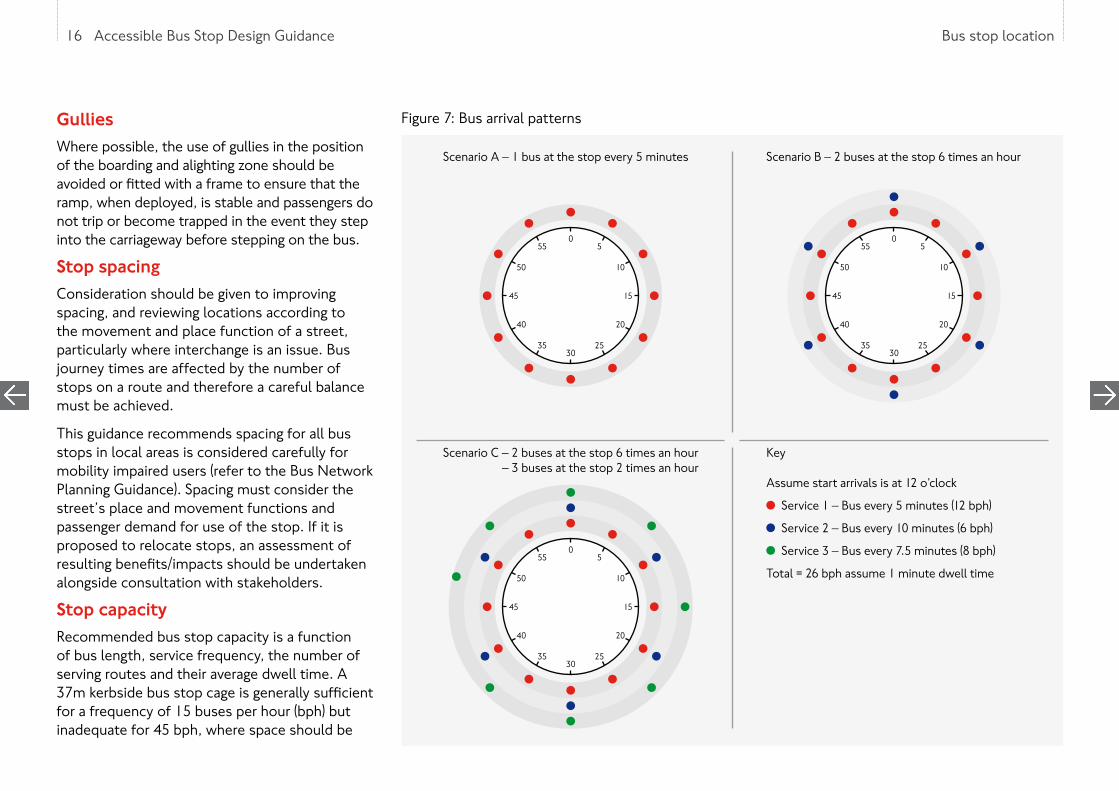
Figure 7: Bus arrival patterns
16 Accessible Bus Stop Design Guidance
055
50
45
40
3530
25
20
15
10
50
55
50
45
40
3530
25
20
15
10
5
055
50
45
40
3530
25
20
15
10
5
Scenario A – 1 bus at the stop every 5 minutes
Scenario C – 2 buses at the stop 6 times an hour – 3 buses at the stop 2 times an hour
Scenario B – 2 buses at the stop 6 times an hour
Key
Assume start arrivals is at 12 o’clock
Service 1 – Bus every 5 minutes (12 bph)
Service 2 – Bus every 10 minutes (6 bph)
Service 3 – Bus every 7.5 minutes (8 bph)
Total = 26 bph assume 1 minute dwell time

17 Accessible Bus Stop Design Guidance Bus stop location
provided for more than one bus to access and serve the stop at the same time. Conversely, at bus stops where the number of buses serving the stop is much lower, a shorter cage of 25 metres should be sufficient, subject to swept path analysis demonstrating that a bus can achieve a position flush with the kerb. The ‘Big Red Book’ advises drivers to stop within the cage markings.
Other measures of the capacity of a bus stop include total passenger demand, average dwell time and ease of pulling out from the stop. Decisions on merging or splitting stops should therefore be based on observations of the actual performance of the stop rather than just looking at buses per hour.
The ‘clock-face’ diagram shown in figure 7 indicates how the frequency of services influences the space required at a stop. This shows the estimated volume of buses at a single bus stop, depending on the frequency of the respective services.
For example Scenario C in figure 7 shows that although there is a frequency of 26 bph, the stop, would theoretically operate well below capacity. If there is a dwell time of one minute per bus, the stop should only be occupied for 26 minutes, however the arrival pattern of buses means that at times more than one bus will be on the stop.
It is recognised that at certain locations the number and frequency of bus services may be particularly high, as well as multiple
signals. A bus stop in advance of the signals can have safety implications, as a driver’s forward visibility will be reduced. When at a bus stop, a bus can obscure the nearside signal or obscure a pedestrian leaving the footway to cross the road.
There are locations where a bus stop is better located on the approach side of the junction to serve interchanges and attractions or before routes diverge. If a stop is located on the approach side of the traffic signals, there is a requirement for the primary signal to be visible for at least 70m in an urban environment. A stationary bus in advance of traffic signals will interfere with signals detection if placed less than 40m from stop line. National guidance requires a minimum of 20m of unobstructed space from traffic signals.
Changes in kerb alignment (e.g. bus boarders), or realignment of traffic lanes, may require existing loops (SCOOT, MOVA or X, Y or Z loops) on the approach to junctions to be re-cut or repositioned, so that bus detection at the signals is retained.
Temporary bus stopsTemporary bus stops are provided when permanent stops are out of use, for example because of roadworks or diversions. They should be located as close as possible to the permanent stops, in positions that are safe and do not cause undue disruption and are accessible. Signage at the closed bus stop should indicate the location of the nearest open bus stop.
17 Accessible Bus Stop Design Guidance
requirements for kerbside space, and therefore compromises may have to be made to the length of the cage. This may impact on the bus’ ability to pull up close to the kerb, so only in exceptional circumstances should cage lengths be shortened.
It is recommended that where locations are served by more than 25-30 bph and sufficient space is available, bus stops should be split. This enables buses on different routes to serve separate stops, thus reducing bus-on-bus delay and bus stop congestion. However, it is recommendable for bus routes with common destinations to share the same stop, and this may result in it being preferable to have more than 25 bph on a stop, even where space exists to introduce a split stop. A bus stop that has more multiple routes with lower frequencies is likely to have more times with multiple buses at the stop than a stop with fewer routes at a higher frequency.
Bus stops and traffic signalsBus stops close to traffic signals may require mitigating measures to retain traffic capacity at the signals; for example a central island with additional signal, modified lane markings or a different traffic signals sequence. These are all site specific measures which require consultation with the relevant traffic signals authority. Passengers often prefer the bus stop to be as close to the junction as possible. Ideally, bus stops should be located on the exit side of junctions, where the effect on saturation flows is generally less than stops sited in advance of

18 Accessible Bus Stop Design Guidance Bus stop location
‘Hail & Ride’‘Hail & Ride’ services are where bus services are hailed at any location along a route. Fixed bus stops are preferable as they provide passenger accessibility and can be protected with bus stop ‘cages’, so that buses are physically able to pull up close to the kerb, assisting passengers to board or alight. TfL has a policy of no longer creating new sections of ‘Hail & Ride’ facilities.
‘Hail & Ride’ sections have been introduced where it is difficult to site bus stops but where the presence of a bus service brings benefits to passengers and residents. These services can help older and disabled people as there is a shorter walk to the boarding point.
Outlined below are options to improve accessibility of ‘Hail & Ride’ bus services. Passenger surveys will assist in determining the appropriate solution.
Option 1 – Conversion to fixed stopTfL’s preferred solution is for conversion of ‘Hail & Ride’ to fixed stops where:
• Services have grown in patronage and buses are making frequent stops
• Passenger demand is concentrated at identifiable points
Providing fixed stops provides better customer information and provides a certain location for passengers, which in particular benefits mobility, cognitive and visually impaired passengers. It is
also easier to regulate bus services when there are formal bus stops.
Option 2 – Retention of ‘Hail & Ride’ sections of route It may be appropriate to retain ‘Hail & Ride’ operation:
• On lightly used services
• On routes where passenger demand is very scattered
• Where local conditions make installation of bus stops difficult or sensitive
Where ‘Hail & Ride’ is retained, the following options should be considered to provide improved accessibility.
Option 2a – Provision of information for passengers where ‘Hail & Ride’ sections are already accessible Information posts, which display a bus timetable and other information, can be provided at locations which offer good accessibility to and from buses. However, these posts are not fixed bus stops, they do not have a bus stop flag and buses can still stop at other safe points.
The benefits of these information points are that they provide reassurance to passengers that buses serve the route and they offer a source of information, such as the frequency and destination of buses. The posts also encourage passengers to congregate, rather than waiting at short distances from each other and expecting
the bus to make several stops. The advantage for disabled people is that the benefits of ‘Hail & Ride’ are retained.
Option 2b – Provision of accessible points along ‘Hail & Ride’ sections of routeIt may be appropriate to install accessible boarding and alighting points at intervals along ‘Hail & Ride’ sections of route. Accessible points could, for example, consist of a simple (2m wide x 4m) bus boarder to provide full accessibility whilst minimising the impact on the local environment. Parking restrictions for accessible points without bus stops would require a Traffic Regulation Order, as bus stop clearways cannot be installed without a bus stop flag.
Information posts can also be provided, where appropriate, to explain to passengers that a section of route is ‘Hail & Ride’.
18 Accessible Bus Stop Design Guidance
19 Accessible Bus Stop Design Guidance Passenger waiting area
This chapter considers the requirements of a passenger waiting area. In particular this examines the location of posts, flags and shelters. Discussion of the bus stops’ relationship to the wider footway area and the waiting area environment is provided.
4. Passenger waiting area
20 Accessible Bus Stop Design Guidance Passenger waiting area
4. PASSENGER WAITING AREA
Bus stop post and flagConsideration should be given to the passenger waiting area based on the features of the buses using the bus stop. The overall layout of the passenger waiting area should be based around the bus stop flag’s position which will dictate the design of the waiting area highway markings (clearway or cage) and the street furniture on the pavement. Bus stop cages are covered in chapter 5 and bus stop layouts in chapter 6.
The bus stop flag indicates to passengers where they should wait and serves as a marker to drivers to indicate where the bus should stop. These guidelines are based on the bus stopping with the rear of the front doors in line with the flag and passengers boarding from the downstream side of the flag.
In some circumstances, it may be appropriate to combine the bus stop flag with street lighting, through agreement between TfL and the owner of the lighting column.
Deployment areasThe majority of London’s buses are configured with a powered ramp at the centre door. On shorter buses, without a centre door, the ramp is situated at the front door. Sufficient unobstructed space is required on the footway where the bus stop is located, in line with these
20 Accessible Bus Stop Design Guidance
doors for the ramp to be deployed. Boarding and alighting areas should be kept clear of all obstructions such as litter bins, telephone boxes and sign posts.
The length of clear footway required is defined by the width of the doors. The width of footway needed is defined by the space required for a wheelchair or pushchair to manoeuvre. Typically footway widths should be a minimum of two metres in existing conditions, especially in areas identified with the highest strategic place function in the Street Types for London matrix (see figure 1). It may be difficult in existing situations where there are physical constraints to deliver this basic level of physical accessibility. The DfT’s Inclusive Mobility Guidelines state that a skilled manual wheelchair user should be able to complete a 360° turn in a space of 1500mm x 1500mm, therefore this is the minimum physically possible space. A minimum of three metres should be provided for footway widths in new developments to allow for through pedestrians and people waiting. Consideration should also be given to wider footways in busier areas, such as ‘City hub’ in figure 1, to segregate passenger waiting at stops and regular pedestrian flow.
Bus passenger shelterBus shelters play a valuable role in delivering a broader measure of accessibility but can also help shape people’s perception of place especially in areas with specific character, such as ‘High streets’ in figure 1. The shelter will
protect people from extremes of weather with lighting to help them feel more secure. Seating is provided to assist mobility impaired passengers that do not use wheelchairs, such as ambulant disabled and older passengers.
Countdown bus passenger information is currently included at over 2,500 bus shelters across London. Providing bus arrival information can make users feel more comfortable and secure.
Every bus stop also has a unique code displayed which passengers can text or use the TfL website to receive bus journey time information. Shelters also provide important opportunities to consolidate street furniture (maps, signage) into a single structure.
Figures 8 to 10 illustrate three general layouts for the bus passenger shelter.
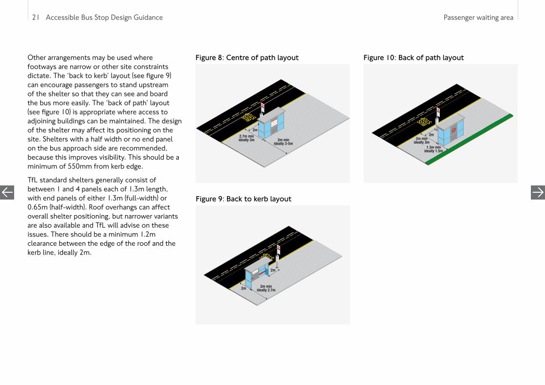
The ‘centre of path’ layout (see figure 8) enables passengers to shelter, see approaching buses, and board with ease. In addition, this layout, if on the approach side of the stop, allows wheelchair users who may wish to wait by their boarding position at the centre doors to be protected from the weather. Where the New Bus for London operates three-door boarding configuration, this layout helps to spread boarders between the doors. The edge of roof should be a minimum of 550mm away from the kerb edge. A minimum of 1.2m clearance behind the shelter is recommended to ensure wheelchairs and buggies can pass.
21 Accessible Bus Stop Design Guidance Passenger waiting area
Other arrangements may be used where footways are narrow or other site constraints dictate. The ‘back to kerb’ layout (see figure 9) can encourage passengers to stand upstream of the shelter so that they can see and board the bus more easily. The ‘back of path’ layout (see figure 10) is appropriate where access to adjoining buildings can be maintained. The design of the shelter may affect its positioning on the site. Shelters with a half width or no end panel on the bus approach side are recommended, because this improves visibility. This should be a minimum of 550mm from kerb edge.
TfL standard shelters generally consist of between 1 and 4 panels each of 1.3m length, with end panels of either 1.3m (full-width) or 0.65m (half-width). Roof overhangs can affect overall shelter positioning, but narrower variants are also available and TfL will advise on these issues. There should be a minimum 1.2m clearance between the edge of the roof and the kerb line, ideally 2m.
21 Accessible Bus Stop Design Guidance
Figure 8: Centre of path layout
2.7m minideally 3m 2m min
ideally 3-5m
2m
Figure 9: Back to kerb layout
2m 2m minideally 2.7m
2m
Figure 10: Back of path layout
2m minideally 3m
1.3m minideally 1.5m
2m
22 Accessible Bus Stop Design Guidance Passenger waiting area
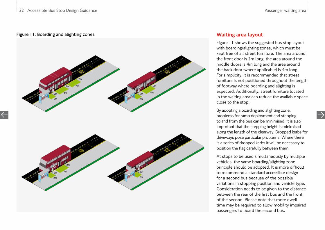
Waiting area layoutFigure 11 shows the suggested bus stop layout with boarding/alighting zones, which must be kept free of all street furniture. The area around the front door is 2m long, the area around the middle doors is 4m long and the area around the back door (where applicable) is 4m long. For simplicity, it is recommended that street furniture is not positioned throughout the length of footway where boarding and alighting is expected. Additionally, street furniture located in the waiting area can reduce the available space close to the stop.
By adopting a boarding and alighting zone, problems for ramp deployment and stepping to and from the bus can be minimised. It is also important that the stepping height is minimised along the length of the clearway. Dropped kerbs for driveways pose particular problems. Where there is a series of dropped kerbs it will be necessary to position the flag carefully between them.
At stops to be used simultaneously by multiple vehicles, the same boarding/alighting zone principle should be adopted. It is more difficult to recommend a standard accessible design for a second bus because of the possible variations in stopping position and vehicle type. Consideration needs to be given to the distance between the rear of the first bus and the front of the second. Please note that more dwell time may be required to allow mobility impaired passengers to board the second bus.
Figure 11: Boarding and alighting zones
4m
2m
2m
2m
2m
2m 4m
2m
2m
4m2m
2m 4m
2m
2m
2m

23 Accessible Bus Stop Design Guidance Passenger waiting area
Footway width and pedestrian flowsThe passenger waiting area where the passengers board and alight should be designed to allow sufficient space for the stop infrastructure, such as shelters and pedestrian through movement. Research has shown that simple interventions can make the pedestrian environment more comfortable. These are detailed in the TfL ‘Pedestrian Comfort Guidance’ and the advice on the waiting area layout earlier in this chapter.
At locations with a higher place function which attract large numbers of people, it may be necessary to widen the footway and this can often be achieved through the provision of a bus boarder (see chapter 7).
Figure 8 shows that the ‘centre of footway’ shelter layout should leave at least 2.7m (3m is preferred) between the kerb edge and the rear of the shelter for wheelchair users to manoeuvre. The gap between the shelter and the rear of the footway in busy conditions should have an unobstructed width of at least 2m. Therefore, a footway width of 3-5m is recommended, depending on pedestrian flows.
‘Back to kerb’ and ‘back of path’ layouts (see figures 9 and 10) also need to leave an unobstructed width of at least 2m for pedestrians. Larger unobstructed widths are recommended, but where unobstructed widths of over 3m can be achieved, a ‘centre of footway’ shelter configuration should be considered instead. ‘Back of path’ layouts with
large widths will make it difficult to board the bus as boarding passengers may conflict with pedestrians walking along the footway and increase bus stop dwell time.
Footway widths are effectively reduced by street furniture such as telephone boxes, lamp columns, litter bins and parking ticket machines. Observations suggest that bus passengers have a tendency to wait for a bus in a linear pattern, adjacent to the road or to the back of the footway. At busy bus stops, queues can form upstream of the bus stop flag, therefore unobstructed areas should be created within the entire zone where possible, by moving street furniture downstream of the bus stop, rationalising it or removing it altogether. This will help visibility of approaching buses as well as increasing pedestrian space. A simple audit of features in and around bus stops should aim to:
• Reduce street clutter
• Optimise bus stop location including spacing
• Optimise shelter location
• Consider other boundary effects
Pedestrian counts should be undertaken when designing accessible bus stops for locations with high pedestrian volumes such as retail areas. These counts should be undertaken during appropriate peak periods, based on the location’s characteristics, for example Saturday 10am to
5pm in a retail area. Counting pedestrian flows to public transport interchanges and across roads should also be considered.
Waiting area environmentThe environment of the passenger waiting area is an important component of passengers’ perception of the quality of the bus service and safety.
A number of other issues should be considered:
• Crime: The perception of crime can influence the environment of bus stops and consequently have an impact on the desirability of the location. Poorly located street furniture can lead to an increase in crime and fear of crime, especially in less busy areas which attract unfamiliar users from a wide catchment like ‘City places’ (see figure 1).
There is a statutory duty for all highway authorities under Section 17 of the Crime & Disorder Act 1998 to do all they can to prevent crime in all of its undertakings, which includes the provision of bus stops and shelters. It is, therefore, necessary that a crime and disorder assessment be undertaken for all new bus stops and shelters. This can be provided by TfL’s Enforcement and On-street Operations, and will help highway authorities to show that crime prevention has been considered carefully.
23 Accessible Bus Stop Design Guidance

24 Accessible Bus Stop Design Guidance Passenger waiting area
• Street lighting: Inadequate street lighting can contribute to issues of personal security. Good levels of illumination should be provided at all bus stops and should aim to achieve a distribution of light that is spread evenly with uniformity. White light is preferable as this can improve colour rendering qualities and can have a positive impact on users by reducing feelings of insecurity and fear of crime.
• Litter: A clean passenger waiting area improves the passengers’ environment. Litter bins should be provided but with consideration of locating litter bins to reduce nuisance, such as smells and flies, and avoid obstruction to pedestrian and passenger movement. They should also be emptied regularly by the local authority.
• Utilities: Utilities are likely to be present at bus stop locations and can affect the positioning of bus stop flags and passenger shelters. Service covers can also create long term problems at the bus stop owing to access requirements to the equipment. Consideration should be given to the boarding and alighting zone to avoid access difficulties during maintenance works.
• Drainage: Poor drainage, resulting in water ‘ponding’ on the footway around the passenger waiting area or at the carriageway kerbside, can affect the passenger environment. Ponding may also result from defective carriageway repairs, or blocked drains. In freezing conditions ponding on footways can turn to ice, creating dangerous conditions for
pedestrians. Ponding at the kerbside can result in passengers being splashed by passing traffic (or the bus) and it is, therefore, important that good drainage is provided and that footways in the vicinity of the bus stop are level to ensure surface water drains off efficiently.
• Green infrastructure: Green infrastructure – including street trees, woodlands and individual elements such as green walls – is hugely important to London, delivering significant environmental, economic and social benefits including improved air quality, mitigation of the urban heat island effect, floodwater management and reduced traffic speeds. Unlike other highway assets, trees and other vegetation are dynamic, living and growing organisms.
Under certain circumstances green infrastructure can have negative impacts such as obstruction of street lights and sight lines, low branches and conflicts with buildings or other infrastructure. These conflicts can largely be avoided through good planning of new bus stops in relation to green infrastructure. Adequate maintenance, inspection and monitoring of green infrastructure at bus stops should help identify and reduce conflicts before they occur. Specialist advice should be sought where pruning or removal might be required.
TfL has an in-house team of arboriculture and landscape experts who are available to assist. Additional information relating to trees can be found on the London Tree Officers Association website at www.ltoa.org.uk
24 Accessible Bus Stop Design Guidance

25 Accessible Bus Stop Design Guidance Bus stop area
This chapter provides guidance on carriageway markings; in particular bus stop cages and clearways.
5. Bus stop area

26 Accessible Bus Stop Design Guidance Bus stop area
5. BUS STOP AREA
Bus stop cageThe bus stop marking on the carriageway are often referred to as the bus ‘cage’, (TSRGD diagram 1025.1) and defines the limits of the bus stop. The purpose of the bus stop cage should not merely be seen as identifying a stopping point. The bus stop cage defines an area of the carriageway where the bus can perform the following unobstructed:
• Approach the bus stop
• Straighten up in line with the kerb
• Stop at the bus stop
• Exit the bus stop
It is a key requirement that a bus stop cage marking is provided, and the area defined by the cage is unobstructed to allow easy entry and exit for the bus. The aim is that buses pull up within 200mm from the kerb. Layouts to achieve this are illustrated in chapters 6 to 8.
The length of the bus stop cage will vary depending on the highway layout, the size of buses, and number of buses per hour using the stop.
Bus stop cages are usually 3m wide; however, designers should be aware that the TSRGD does allow for a ten per cent variation in road markings (TSRGD, Clause 7 (9) of Part 1). This allows cage widths of 2.7m where carriageway widths are reduced, and there is some evidence to suggest that narrower 2.7m wide cages encourage bus drivers to stop closer to the kerb.
Bus stop clearwaysWithin the cage area, no stopping by vehicles other than buses should be permitted. Bus stops located on the TLRN, are generally marked with double red lines. To achieve this on borough roads a yellow clearway marking
must be provided in accordance with TSRGD diagram 1025.1.
In some cases, on the TLRN, a wide red clearway line is provided to indicate that only buses can stop to prohibit taxis from setting down and picking up. These have been successful in reducing the number of conflicting movements between buses and other vehicles, particularly taxis.
26 Accessible Bus Stop Design Guidance

27 Accessible Bus Stop Design Guidance Bus stop layouts
This chapter outlines the relationship between buses and kerbside activity, and how to reduce its impact.
6. Bus stop layouts

28 Accessible Bus Stop Design Guidance Bus stop layouts
6. BUS STOP LAYOUTS
IntroductionBus stops unobstructed by kerbside activity are rare. It is usually necessary to find a means to sufficiently encourage motorists to keep the bus stop clear. As discussed in chapter 5, generally all bus stops should have a marked cage as per TSRGD diagram 1025.1 with stopping restrictions operating 24 hours a day.
37m is the recommended bus cage length where parking is located either side of the stop, and should be provided wherever possible. 25m lengths have been used; however this length of cage does not provide enough space to smoothly pull up to within 200mm of the kerb to allow ramp deployment, 33m is the minimum space required to allow ramp deployment. Figure 12 shows layouts for 12m rigid buses where the bus stop has parking bays on both the approach and exit sides of the stop. The clear kerbside space is required to allow convenient and efficient bus access to within 200mm of the kerbside.
Cage lengthThe cage length required will also depend on the width of waiting and loading boxes on the approaches/exits. Where wider loading boxes are situated on the approach/exit then additional space is required because of the increased lateral movement.
It is possible to change the bus stop layout including the cage length and still ensure a bus can access the bus stop. There are two convenient locations for bus stops where this can be achieved:
• The exit side of a pedestrian crossing (see figure 13)
• The exit side of a junction (see figure 14)
These two layouts assist bus access whilst minimising the length of bus stop clearway. They also have the advantage of placing stops near to where passengers may wish to cross the road. Safety issues must always be considered when adopting such designs. It is important to plan the cage size for the frequency of buses; otherwise following buses could block the crossing or side road (see chapter 3 for further information).
It should be noted that buses are permitted to stop on the exit side of zig-zag markings at
pelican and zebra crossings to pick up or set down passengers. Reducing the length of exit side zig-zag markings, is not recommended.
Junction proximityMost junctions on bus routes have some kerbside controls. However, problems can occur as a result of vehicles stopping between the cage and junction, even with kerbside restrictions. In practice marked bus cages with stopping restrictions are more effective at discouraging vehicles stopping in this area and are easier to implement. An extension to the cage to prohibit stopping on the approach is shown in figure 12.
Any relocation of the stopping position of the bus closer to the junction should have regard to visibility for drivers of vehicles leaving the side road. While a bus using the stop is a temporary obstruction, the bus stop post or flag, passenger shelter and waiting passengers should not unduly obscure sight lines.
Figure 12: Kerbside approach with parking on approach and exit
28 Accessible Bus Stop Design Guidance
37.0mOverall length
15.0mStraightening distance
13.0mEntry taper
9.0mExit taper
Shelter Bus stop flag
2.1m Parking2.1m Parking

29 Accessible Bus Stop Design Guidance Bus stop layouts
Figure 13: Exit side of pedestrian crossing
Figure 14: Exit side of junction
Bus manoeuvresAt locations where buses are required to manoeuvre around parked vehicles to pull up to and away from the stop, designers need to consider the implications of reducing the cage dimensions illustrated in figures 12 to 14.
A clear exit distance of 9m is recommended as the minimum necessary for buses to leave the stop and rejoin the general traffic lane without the rear of the vehicle overhanging the kerb in the vicinity of waiting passengers. In some highly constrained situation, this dimension could be reduced to an absolute minimum of 7m.
Alternative solutionsThere will be situations where none of the kerbside designs illustrated can be implemented without seriously affecting existing kerbside activity or general traffic operations. This often arises at busy stops, which require the kerb to be kept free from any other activity.
In many cases, stop accessibility will be hampered by legal or illegal waiting or loading on the approach to the bus stop. In such cases, it may not be physically possible for the rear of the bus to manoeuvre close to the kerb. In other situations, site constraints may prevent conventional layouts from being implemented. Situations that cause problems for the siting of conventional kerbside bus stops include:
• Where there are loading or parking bays which cannot be moved without causing undue inconvenience for frontage users
• Where existing restrictions are neither observed nor effectively enforced
In such cases, a solution may be to alter the kerb line to assist bus access; e.g. a bus boarder (as detailed in chapter 7).
29 Accessible Bus Stop Design Guidance
23.0mOverall length
14.0mStraightening distance
9.0mExit taper
Shelter Bus stop flag
2.1m Parking
29.0mOverall length
20.0mStraightening distance
9.0mExit taper
Shelter Bus stop flag
2.1m Parking
18.0mEntry taper
2.1m Parking
10.0mR6.0m

30 Accessible Bus Stop Design Guidance Bus boarders
This chapter provides guidance on how to implement bus boarders.
7. Bus boarders

31 Accessible Bus Stop Design Guidance Bus boarders
7. BUS BOARDERS
Bus boardersBus boarders are generally built out from the existing kerb line and provide a convenient platform for boarding and alighting passengers. These are implemented where for example, parking separates traffic from the kerb, reducing how far a bus must deviate to enter a bus cage. There are two conventional types of bus boarder, full-width (figure 15) and half-width (figure 18). There are also variations on the bus boarder concept; for example, 500mm build-outs in the downstream section of bus bays. Care should be taken when building bus boarders that the necessary drainage has been provided.
The full-width boarder offers by far the best solution for both bus and passenger access whilst minimising the kerb length required. Full-width boarders also serve to enhance the image of the bus service by providing a waiting area that can be separated from the adjacent pedestrian flow, and thus move towards the standards achieved by tram and light rail systems.
Full-width boardersA full-width boarder should project far enough into the carriageway for the bus to avoid manoeuvring past parked vehicles. For cars this should be at least 2m and a minimum of 2.6m where goods vehicles/vans are stopping. The total length of the boarder will depend on the
31 Accessible Bus Stop Design Guidance
Figure 15: Full-width boarder17.0m
Overall length
ShelterBus stop flag
Reflectorised bollards2.5m Loading 2.5m Loading
Figure 16: Alternative full-width boarder layouts9.0 to 13.0m
Overall length
Shelter
Bus stop flagReflectorised bollards
2.5m Loading 2.5m Loading
3.0mOverall length
Bus stop flag
Reflectorised bollards2.5m Loading 2.5m Loading
9.0 to 13.0mOverall length
Shelter
Bus stop flagReflectorised bollards
2.5m Loading 2.5m Loading
3.0mOverall length
Bus stop flag
Reflectorised bollards2.5m Loading 2.5m Loading
Figure 17: Multiple bus full-width boarder 35.0m
Overall length
9.0m
ShelterBus stop flag
Reflectorised bollards2.5m Loading 2.5m Loading

32 Accessible Bus Stop Design Guidance Bus boarders32 Accessible Bus Stop Design Guidance
vehicle types that serve the stop in addition to the bus frequency. Figure 15 shows typical full-width boarders.
The benefits of a full-width boarder include:
• Minimising the kerbside space required
• Detering illegal waiting or loading
• Maintaining the place of the bus in the traffic stream
• Allowing the bus to line up parallel to the kerb, largely without manoeuvres
• Reducing total boarding/alighting time
• Reducing overall time spent at the bus stop
• Creating additional footway space for passengers to wait in shelter and allows regular pedestrian flows to continue unhindered
• Reducing buses from swinging over kerbs
These boarders maintain the position of the bus in the traffic stream, simplifying access and improving bus reliability, as the bus is not delayed waiting to rejoin the traffic stream.
Full-width boarders should not be used where the frequency of buses or their dwell times will cause delay to following buses and significant delays to general traffic, for example locations with the highest strategic movement function in the Street Types matrix (see figure 1). There may also be circumstances where, for safety reasons, it may not be appropriate to encourage an overtaking manoeuvre by other traffic, such as near the brow of a hill or an approach to a refuge/island.
The design of boarders should provide increased opportunities for the provision of passenger shelters. Bus boarders should therefore be designed to allow cyclists sufficient space to
manoeuvre and avoid unduly sharp deflections on the approach to the build out so that cyclists have sufficient time to move into a primary position. Cycle bypasses should also be considered, where appropriate (see chapter 11).
Layouts for bus boarders to cater for multiple vehicles stopping at a single stop are provided in figure 17. The length of kerbside space required can be reduced by providing a shelter, open towards the kerb, on the existing footway (see figure 16). Where smaller midi type buses serve the stop, and no passenger shelter is provided, it is possible to implement a 3m long boarder.
Figure 18: Half-width boarder
27.0mOverall length
15.0mStraightening distance
8.0mEntry taper
4.0mExit taper
ShelterBus stop flag
2.1m Parking1.0m
2.1m Parking

33 Accessible Bus Stop Design Guidance Bus boarders33 Accessible Bus Stop Design Guidance
Half-width boardersThe half-width boarder is often a useful compromise design (see figure 18). The build-out from the kerb can range from 500mm up to the width of a full boarder, although they are commonly 1.0 - 1.5m wide. They can be used where frequent delays to other vehicles are to be avoided or where a full-width boarder would place the bus in, or too close to, the opposing traffic stream.
In Street Types terms, this may be most relevant to locations where there is higher movement functions as outlined in figure 1. As half-width boarders are a compromise design, they use more kerb space than the full width, as some manoeuvring of the bus is required. Half-width boarders deter illegal waiting or loading close to or within the bus stop cage and the prospects of the bus stopping close to the kerb are improved.
In circumstances where a layout has to cater for more than one bus stopping at the same time, provision should be considered for the second bus to pull out past the first bus and for all doors of each vehicle to have clear kerbside access, unobstructed by street furniture. A half indent also provides space for cyclists to pass buses, whilst passengers are boarding and alighting.

34 Accessible Bus Stop Design Guidance Bus bays or lay-bys
This chapter explains how best to mitigate the negative impacts of bays and lay-bys for buses.
8. Bus bays

35 Accessible Bus Stop Design Guidance Bus bays or lay-bys
8. BUS BAYS
Bus bays (also known as lay-bys) can present operational problems for buses and they should only be used when there are compelling safety or capacity reasons. In circumstances where provision of a new bay is required the layout in figure 19 is recommended. This layout incorporates a build-out to allow buses to turn tightly into the bay. In some circumstances the bay will require additional length, where two or more buses may require access to the bay at one time.
A bus cage with 24-hour stopping controls, to prevent waiting or loading in the stop area, is recommended at all bus stops as a permitted variant to TSRGD diagram 1025. There may also be a need to prohibit waiting or loading on the approach to, and exit from, the bay to allow buses to reach the kerb effectively.
Figures 20 and 21 show modifications to bus bays that can improve bus access to the kerbside. With these layouts, the bus protrudes into the nearside lane and amendments to traffic lane widths may be required. An alternative solution is to fill-in the bus bay completely, providing additional footway space that can be tailored to the boarding and alighting characteristics required.
At locations where there is potential for persistent parking in the bay, another variant is to fully fill a section of the bay, enabling the bus to stop on the main carriageway, whilst retaining a shorter bay for loading activity (see figure 20).
Bus bays require a far greater kerb length than bus boarders, so an assessment of the adjacent
land use is important to understand the place significance and kerbside requirements.
35 Accessible Bus Stop Design Guidance
Figure 21: Half-filled bus bay
Figure 20: Filled-in bus bay with parking/loading
Figure 19: Amended bus bay53.0m
Overall length
18.0mStraightening distance
8.0m 8.5m1.5m
20.0mEntry taper
15.0mExit taper
Shelter Bus stop flag
Bus stop flag
(Existing bus bay)
29.0mOverall length
16.0mStraightening distance
13.0mEntry taper
Shelter2.5m Parking / loadingPossible infilling
Partial in-fill of bus bay
3.0m
3.3m
2.0m
Radii tangent points Radii tangent points
R25.0m R25.0m
53.0mOverall length
18.0mStraightening distance
8.0m 8.5m1.5m
20.0mEntry taper
15.0mExit taper
Shelter Bus stop flag
Bus stop flag
(Existing bus bay)
29.0mOverall length
16.0mStraightening distance
13.0mEntry taper
Shelter2.5m Parking / loadingPossible infilling
Partial in-fill of bus bay
3.0m
3.3m
2.0m
Radii tangent points Radii tangent points
R25.0m R25.0m
Bus encroaches into nearside lane
52.0mOverall length
12.0mStraightening distance
20.0mEntry taper
20.0mExit taper
Shelter Bus stop flag
3.0m
0.5m - 1.0m
Partial in-fill of bus bay
Bus encroaches into nearside lane
52.0mOverall length
12.0mStraightening distance
20.0mEntry taper
20.0mExit taper
Shelter Bus stop flag
3.0m
0.5m - 1.0m
Partial in-fill of bus bay

36 Accessible Bus Stop Design Guidance Kerb profiles and heights
This chapter discusses kerb heights, and in particular crossfalls.
9. Kerb profiles and heights

37 Accessible Bus Stop Design Guidance Kerb profiles and heights
9. KERB PROFILES AND HEIGHTS
Kerb heightsFor new facilities, highway authorities and developers should aim to provide a kerb height of 140mm, as this allows for future road resurfacing, (as shown in figure 5 in chapter 2). Existing kerb heights of between 100mm and 140mm are unlikely to require alteration. However, where kerbs are already being altered at bus stops e.g. to build a bus boarder, consideration should be given to the use of higher kerbs to reduce the step height and reducing the gradient of the ramp deployed for wheelchair access. This will improve access for all bus users including disabled people.
The kerb form is also important to consider. It is sometimes difficult for a bus driver to position their vehicles close to kerbs of traditional design; they are not easily seen from the driver’s cab position and the driver will wish to avoid damage to the vehicle, particularly with 90 degree cornered kerbs which can cause wheel damage. It is, therefore, recommended that smooth angled face kerbs should be considered, particularly at new developments.
Carriageway and footway crossfallsWhere kerb heights are altered, carriageway and footway crossfalls will need to be carefully considered. As a general rule, carriageway crossfalls in the region of 1 in 40, or 2.5%,
should not present any additional difficulties for low-floor buses. For carriageway crossfalls steeper than 2.5%, regrading of the carriageway should be considered.
Footway crossfalls are also important and a steep backfall from the kerb is undesirable. A gradient of no more than 1 in 25 or 4% is advisable. To achieve this, designers may have
to regrade lengths of footway to maintain adequate crossfalls or introduce complex drainage arrangements. A common problem with bus boarders is that works are only undertaken on the build-out, leading to steep crossfalls. Ideally, footways should be regraded to align from the back of the footway but this can add considerably to the cost of works.
37 Accessible Bus Stop Design Guidance

38 Accessible Bus Stop Design Guidance Cycle facilities
This chapter provides guidance on the needs of cyclists at bus stop locations. In particular this provides guidance on ensuring that fully separated cycle links and cycle lanes maintain accessibility at bus stops.
10. Cycle facilities
Exceptcycles
KEEP C
LEAR
ONEWAY

39 Accessible Bus Stop Design Guidance Cycle facilities
10. CYCLE FACILITIES
The number of people cycling on London’s streets has been growing. Significant investment in delivering Healthy Streets, making walking and cycling safer and more attractive, means this growth will continue. It is expected that 1.5 million trips per day will be cycled by 2026.
It is important that the needs of people walking, cycling and using buses are considered when developing all improvements to the road network. With more and more people cycling, it is increasingly likely that cyclists will be present in and around most infrastructure used by buses in London. For the safety and comfort both of cyclists and bus passengers, this interaction needs to be carefully planned and designed.
For any intervention on the road network, a Road Safety Audit needs to be undertaken which must take into account interactions between buses and cyclists; between bus passengers accessing the bus stop and cyclists; and pedestrians using the adjacent footpath and other cyclists within the vicinity.
Chapter 4 of the London Cycling Design Standards contains guidance for shared bus and cycle lanes, as well as for the interaction of cycle tracks and cycle lanes with bus lanes and bus stops. TfL’s Streetscape Guidance also includes the design of bus lanes (section 8.5) and bus stop environments (section 10.6). The advice given in the sections below will help designers of bus infrastructure to conform to all of TfL’s guidance documents.
Designing for cyclists on-carriageway around bus stopsWhere cyclists are on-carriageway, it is important that they are clearly visible to bus drivers, particularly around bus stops. Ideally, cyclists should be able to pass a stopped bus without having to move across into the adjacent lane.
In a wide general traffic lane, TSRGD diagram 1057 cycle symbols may be placed on the carriageway around the bus cage. This helps to encourage cyclists to pass the stationary bus on the offside, rather than stay by the kerb, and to alert other users that cyclists could be overtaking in this way at the bus stop. In a with-flow bus lane, cycle symbols may not be used without site-specific authorisation from the Department for Transport.
Where a cycle lane is present, it will generally need to terminate before a bus stop cage and recommence after it. The continuity of cycling provision can be maintained by marking cycle symbols around the bus stop cage (see figure 22).
On low traffic volume locations with bus routes, centre line removal is recommended in order to promote lower speeds and flexible use of carriageway space around the bus stop.
39 Accessible Bus Stop Design Guidance
Figure 22: Mandatory cycle lane at bus stopDiagram 1057 marking immediately before bus stop cage
Diagram 1049 marking
1.0m between edges of bus stop cage and centre of diagram 1057 marking

40 Accessible Bus Stop Design Guidance Cycle facilities
Bus stop bypassesWhere there is a cycle track between the footway and carriageway, common practice is to create a shared footway around the bus stop to enable pedestrians to access the bus and cyclists to divert around the rear of the bus stop. However, this can be problematic, particularly for pedestrians, unless cycle numbers are very low.
The concept of a bus stop bypass has been developed in order to separate cyclists and pedestrians where larger numbers of users will be present. In a bus stop bypass, a segregated cycle lane or track continues through the bus stop area behind the shelter, thereby creating an island for bus passengers boarding and alighting at the stop. It requires a crossing for pedestrians to access the island across the cycle track. The concept draws on successful examples of similar infrastructure in other cities.
Bus stop bypass design accessibility principlesBus stop bypasses can give rise to concerns about accessibility that do not apply to most other types of bus stops and that need to be specifically addressed in any design proposals.
It is essential that bus stop bypasses are designed to consider the complications that can arise for pedestrians boarding or alighting the bus at a bus stop. This includes consideration not just for those with a visual impairment but for all those with mobility impairments including
passengers with prams or pushchairs or those carrying heavy luggage.
The following accessibility issues therefore need to be addressed through the design process:
• The ability of anyone with a visual, hearing, mobility or cognitive impairment to find the crossing point and to reach the island and then find the bus stop from the island
• The level of comfort and confidence for those crossing the cycle track; particularly in areas with more pedestrians. This includes cyclists being encouraged to act courteously, slowing down on the approach to a crossing and giving way as necessary
• The consistency of basic layout designs. This should ensure that anyone who has been guided through using one bus stop bypass is able to use any such facility with confidence, even though dimensions and other design details will be location specific
Any proposal for a bus stop bypass should be consulted at the earliest possible stage with potential users, particularly groups representing those with visual, mobility, hearing or cognitive impairment who may be most at risk when crossing a cycle path to access the bus stop.
Bus stop bypass design guidanceTo address the comfort and accessibility issues outlined above, it is recommended that any bus stop bypass design should incorporate the following:
• Enough space for the wheelchair ramp to deploy from the bus and for the wheelchair user to be able to turn on the island in order to get on or off the ramp. The island should be at least 2.5 metres wide in order to allow this to take place in comfort
• The size of the bus stop island must also be adequate for the number and frequency of bus services and for current and predicted future pedestrian flows. More than 2.5 metres in width is therefore likely to be required where significant bus passenger activity is observed. This is particularly important where coaches are in operation to allow for loading and unloading of passengers and their luggage
40 Accessible Bus Stop Design Guidance

41 Accessible Bus Stop Design Guidance Cycle facilities
• The length of a bus stop needs to consider bus flows using the stop; such as high frequency bus routes, and where driver changeovers occur
• Pedestrian amenity on the footway should not adversely be affected by the introduction of a bus stop bypass, with pedestrian level of service ‘C’ achieved as a minimum, although comfort level ‘B’ is preferred. It is recommended that 2 metres clear width of footway should be retained. Wider footway widths should be considered where there are other street uses such as pubs or cash machines which are likely to cause obstruction
• Appropriate delineation of the footway, cycle track and the bus stop island should be provided, preferably differentiated by level. Any kerb upstand should be at least 50mm. Angled kerbs should be considered, to provide sufficient width for cycling where upstands are higher
• A bus passenger crossing point must be provided, clearly identified with blister tactile paving and with kerbs that are flush with the cycle track. Long bypasses with high usage may need multiple crossing points to enable safe bus passenger access and egress
An indicative layout of a bus stop bypass illustrating these features is shown in figure 23.
Designers of bus stop bypasses should also consider the following:
• Cycle slowing measures to encourage cyclists to slow down and allow bus passengers to cross; this may include narrowing the cycle track behind the bus stop
• Targeted publicity and messaging, such as iBus stop announcements, should be considered when any new facility is being introduced to ensure bus passengers understand the changes
• Visual contrast, ideally 50 per cent difference, should be provided between both the crossing area and the footway with the cycle track, to alert cyclists to the crossing, alert bus passengers to the cycle track and to highlight the crossing area for bus passengers with vision impairment
• The bus stop island requires sufficient space (minimum of 2.5m width) for a wheelchair
ramp to be deployed and for wheelchair users to safely manoeuvre. In particular, attention must be given to the location of any shelters, the flag and the cage length to ensure that the shelter does not obstruct the first bus stopped at the front of the cage, rather than at the flag. The positioning of bins and other street furniture to avoid obstruction should also be considered
• Good inter-visibility between cyclists and bus passengers must be achieved. The introduction of any bus stop shelter that incorporates advertising and information panels needs to be done in a way that avoids blocking sight lines, particularly on bidirectional tracks
• The types of bus shelters introduced on bus stop bypasses should consider the visibility splays for cyclists rejoining the main roadway
41 Accessible Bus Stop Design Guidance
Figure 23: Indicative bus stop bypass layout
42 Accessible Bus Stop Design Guidance Cycle facilities
• The cycle track must accommodate comfortable passage by any cycle, which means sufficient width and suitable geometry (to account for non-standard cycles and for current and projected cycle flows), smooth vertical changes and avoidance of vertical deflections other than sinusoidal or shallow ramps
Crossing the cycle track at bus stopsThe cycle track crossing should be on the main identified pedestrian desire line. It is recommended that this should be on a raised table, providing a level surface for bus passengers/pedestrians and those in wheelchairs to access the island, while reducing speed and encouraging courtesy from cyclists. The crossing should be of sufficient width to accommodate expected pedestrian volumes at peak flow times of day.
More than one crossing point should be considered where there is more than one flag at a given stop or, potentially, where there are large numbers of bus passengers, and pedestrian desire lines do not align with a single crossing location.
Consideration needs to be provided for blind and partially sighted bus passengers so that they can navigate towards the bus stop flag.
These measures might include zebra crossings at appropriate locations.
Greater priority for bus passengers and pedestrians may be desirable, particularly where there are high flows of bus passengers, cyclists and pedestrians. Following the publication of TSRGD (2016), a variant type of zebra crossing has been available for use on cycle tracks to achieve this. Criteria for its use will be developed through on-street trials. See sections 5.2.10 and 5.3.4 (indicative layout 5/07) of the London Cycling Design Standards for further detail on options for crossing cycle tracks.
Further guidanceCurrently cycling infrastructure at bus stops is being monitored, as these are innovative techniques being developed for London, to understand the impacts for all road users.
Existing bus stops lengths and locations should be retained wherever possible. If the bus stop position in relation to the kerb line has changed, the length of the entry and exit taper of the bus stop should be reviewed. If significant changes are being considered as options, scheme designers and promoters should liaise with TfL at the earliest stage possible.
An evaluation of bus passenger benefits and disbenefits, including potential adverse impacts to safety, service reliability, and journey times should be provided where significant changes are taking place.
42 Accessible Bus Stop Design Guidance
The London Cycling Design Standards, and other relevant guidance, should be consulted for technical design guidance for the design of any cycling measures.
43 Accessible Bus Stop Design Guidance Longer term issues
This chapter considers a number of other topics including Street Types, shared and level surfaces, maintenance, enforcement and audio information.
11. Other considerations

44 Accessible Bus Stop Design Guidance Longer term issues
11. OTHER CONSIDERATIONS
Streets ToolkitThe design approach to streets is continually evolving in London. In recent years, there has been a greater recognition within guidance documents for the need to transform the quality of streets. The TfL Streets Toolkit including Streetscape Guidance is continually being developed to ensure the TLRN maintains the highest levels of accessibility.
The principles demonstrated through Street Types and specific TfL guidance can be applied to all roads in London. They clearly highlight how the interaction between street and bus stop design is vitally important, particularly to embrace accessibility, inclusiveness and equality.
The Street Types framework takes account of local and network priorities, and aims to guide policy and investment decisions, to provide a basis for allocating road space. This can also be used as a means of establishing the appropriate levels of service. It noted that while progress has been made in recent years, there are many pressing and interrelated accessibility challenges ahead.
Shared and level surface schemesShared and level surface schemes are where a kerb is the same level as the road. These can have an impact on the accessibility of bus stops which are required to be at a specific height to align with bus doors. All stops need to be equally accessible to enable all passengers to board and alight at their desired location. The removal of kerbs increases the step height from the footway to the bus and has a negative impact on the effective deployment of the bus passenger ramp.
When designing shared or level surface schemes where bus stops infrastructure is in existence, particular attention is needed to minimise creating trip hazards by also ensuring adequate surface contrast for visually impaired people, as well as drainage and suitable lighting around the stop.
The Royal Borough of Kensington & Chelsea implemented a fully accessible level surface space on Exhibition Road with reduced traffic congestion and provided more room for
pedestrians, that maintains accessible bus stop infrastructure. The design is such that there are no kerbs except at two locations where ‘platforms’ have been built and corduroy paving is used to delineate the space for bus stops.
It is important to recognise that design for bus stops in shared or level surface schemes should be site specific. Designers should, therefore, consult London Buses at an early stage to ensure suitable advice is provided.
Maintaining bus stop accessibilityTfL and other highway authorities are investing considerable money, time and effort to make London’s bus stops accessible. This investment and the resulting increased accessibility for bus passengers needs to be maintained.
Small changes to the bus stop environment can make bus stops inaccessible.
Highway authorities need to be aware of the impacts of any interventions such as the positioning of street furniture or changes to the bus stop kerb. Any intervention in the bus stop area that prevents a bus being able to pull up parallel to the kerb and deploy its ramp should be avoided.
44 Accessible Bus Stop Design Guidance

45 Accessible Bus Stop Design Guidance Longer term issues
MaintenanceTfL is responsible for the bus stop flags and the majority of bus passenger shelters, while local highway authorities have responsibilities for maintenance of bus stop areas. This can include street cleaning, maintenance of the footway and carriageway surfaces in the vicinity of the bus stop, vegetation such as trees and winter maintenance.
The carriageway, and potentially the kerb, in the vicinity of the bus stop are subject to particular stresses from the repeated manoeuvres of buses. Materials used in these areas should be durable and any faults quickly remedied. In the course of normal maintenance routines, carriageways will be resurfaced using a variety of methods. During resurfacing it is crucial that the kerb height at bus stops is maintained or improved. It is common for the general level of the carriageway to rise with successive surface repairs. This not only increases stepping heights and ramp gradients, to the detriment of passengers, but also increases crossfalls, causing additional problems for buses and reducing the efficiency of draining surface water.
In all cases where levels are being altered, careful consideration must be given to adequate drainage of the site, particularly in relation to adjacent properties.
EnforcementMany boroughs now use CCTV to enforce bus stop clearways and waiting and loading restrictions, and this can contribute to improving compliance.
Audio informationAudio information is not currently provided at bus stops in London. TfL is looking at options to provide independent audio information to help blind and partially sighted people find their way around the network independently. Trials of audio information at bus stops carried out in 2010 were unsuccessful due to objections from local residents. TfL will continue to keep this issue under review.
45 Accessible Bus Stop Design Guidance

46 Accessible Bus Stop Design Guidance Longer term issues
A full list of references and an appendix listing the dimensions of a number of London bus vehicles is provided.
12. References/data sources and Appendix

47 Accessible Bus Stop Design Guidance References/Data sources
12. REFERENCES/DATA SOURCES
• Barham P. et al. (1994) ‘Accessible Public Transport Infrastructure - Guidelines for the Design of Interchanges, Terminals and Stops’, Mobility Unit of the Dept. of Environment, Transport and the Regions and the Passenger Transport Executive Group
• Roads Service Transportation Unit (N.I.) (2005) ‘Bus Stops - A Design Guide for Improved Quality’, Roads Service and Translink
• Dejeammes M. (1997) ‘Accessible Low-Floor Bus - System Approach in France’, Transportation Research Record 1604, pp 163-169
• Department for Transport (2016) ‘The Traffic Signs Regulations and General Directions’
• Department of the Environment, Transport and the Regions (1998) ‘Guidance on the Use of Tactile Paving Surfaces’
• Disabled Persons Transport Advisory Committee (1997) ‘Recommended Specification for Low-Floor Buses’
• Hall S, and Desyllas J (2006) ‘Bus stops – how peoples actually use them and the implications for design, Association for European Transport and contributors
• Chartered Institution of Highways and Transportation (2015) ‘Streets and Transport in the Urban Environment’
• Lavery I. and Davey S. (1996) ‘The Pedestrian Environment - The Achilles’ Heel of Travel by Low Floor Bus?’, Proceedings of Seminar F, PTRC
• Roads Task Force (2013) ‘The vision and direction for London’s streets and roads’
• Transport for London (2006) ‘Accessible Bus Stop Design Guidance – Bus Priority Team technical advice note BP1/06’
• Transport for London (2016) ‘Streetscape Guidance’
• Transport for London (2010) ‘Pedestrian Comfort Guidance for London’
• Transport for London (2013) ‘Delivering the vision for London’s streets and roads: TfL’s response to the Roads Task Force’
• Transport for London (2014) ‘London Cycle Design Standards’
Further informationFor further details or advice on the design of bus stops, contact:
• Surface Strategy & Planning Transport for London, 11th Floor, Palestra, 197 Blackfriars Road, London SE1 8NJ
• Enforcement and On-Street Operations Transport for London, 9th Floor, Palestra, 197 Blackfriars Road, London SE1 8NJ
• Website tfl.gov.uk
47 Accessible Bus Stop Design Guidance

48 Accessible Bus Stop Design Guidance Appendix A – Bus Measurements
APPENDIX – BUS MEASUREMENTS
Vehicle characteristicsThe vehicle characteristics to be taken into account include:
• length of vehicle; type of bus i.e. midi, double deck
• door locations and clear entry and exit widths
• floor height at doors
• ramp position and length
• swept path
• overhang between nearside of bus bodywork and front nearside tyrewall
• external clearance height along nearside of bus
• ground clearance at points where the bus might potentially overhang the kerb
Within these guidelines, unless indicated otherwise, the layouts as provided are based upon a 12 metre bus with front and centre doors and a ramp at the centre door. This is to take into account a ‘worst case’ in the context of potential future operations.
It is recommended that bus stops are designed, as a minimum, to accommodate the ‘standard’ bus, with the following range of vehicle dimensions, such that wherever practical, designers can build appropriate dimensional tolerances.
‘Standard’ rigid bus dimensions• Width: up to 2.55m
• Length: up to 12.00m
Door dimensions• Width: 1.1m
• Distance between 4.8m to 6.0m doors (between centre lines of doors)
• Length of up to 1.0m extended ramp
Heights between carriageway surface and bus floor (approximate)• Front door: 325mm (normal) 240mm (kneeling)
• Centre door: 335mm (normal) 250mm (kneeling)
48 Accessible Bus Stop Design Guidance

49 Accessible Bus Stop Design Guidance
Chassis Body Type Overall length
Front overhang
Wheel base
Rear overhang
Overall height
Floor height laden
Floor height
kneeledApproach
angleDepart angle
Overall width
Turning circle
Wrightbus Streetlite DF Midi bus 10,933 2,500 5,667 2,766 3,173 310 245 8 7 2,550 21,290
Wrightbus Street-deck
Double deck
10,492 or 10,567 Stealth
2,532 or 2,607
Stealth5,400 2,560 4,395 325 245 7 7 2,550 20,294
Volvo B5LH
Wright Gemini 3 HEV
Double deck
10,492 or 10,567 Stealth
2,532 or 2,607
Stealth4,820 3,140 4,395 325 245 7 7 2,550 19,330
Dennis Trident 2 Euro 6 TB 100 Hybrid
ADL E400
ClassicDouble
deck 10,345 2,650 5,250 2,445 4,420 325 250 7.5 6.8 2,550 19,884
Dennis Trident 2 Euro
6 TB100 Hybrid
ADL E400 MMC
Double deck 10,355 2,650 5,250 2,455 4,300 323 250 7.5 7.4 2,550 19,710
Volvo B5L Euro 6 Hybrid
ADL E400 MMC
Double deck 10,576 2,720 4,820 3,037 4,300 305 250 7.7 7.7 2,550 18,920
Dennis Dart Euro
6
ADL E200 MMC
Single Deck 10,870 2,500 5,775 2,595 2,866 317 250 7.4 7.4 2,495 21,682
Vehicle dimensions for a variety of buses in service in London
Appendix A – Bus Measurements

50 Accessible Bus Stop Design Guidance
Chassis Body Type Overall length
Front overhang
Wheel base
Rear overhang
Overall height
Floor height laden
Floor height
kneeledApproach
angleDepart angle
Overall width
Turning circle
Optare Solo
pre-2011Optare Minibus 9,542 655 6,225 2,562 2,730 265 200 39 8 2,466 18,990
Optare Solo SR
post-2011Optare Minibus 9,960 815 6,575 2,570 2,872 265 200 27 8 2,507 21,334
Optare MetroCity Optare Single
Deck 10,820 2,430 5,820 2,570 2,850 318 245 7 8 2,474 21,444
WrightbusNew
Route- Master
Double deck 11,232 2,611 6,000 2,621 4,420 325 245 7 7 2,550 21,800
Vehicle dimensions for a variety of buses in service in London (cont.)
Appendix A – Bus Measurements

Further InformationFor further details or advice on the design of accessible bus stops, contact:
Public Transport TeamSurface Strategy & PlanningTransport for London197 Blackfriars RoadLondon SE1 8NJ
[email protected] ©Transport for London January 2017