accounting for timing biases between gps, modernized gps ... · 36th annual precise time and time...
TRANSCRIPT

36th Annual Precise Time and Time Interval (PTTI) Meeting
ACCOUNTING FOR TIMING BIASES BETWEEN GPS, MODERNIZED GPS, AND GALILEO SIGNALS
Chris Hegarty Center for Advanced Aviation System Development
The MITRE Corporation Bedford, MA 01730-1420, USA
E-mail: [email protected]
Ed Powers and Blair Fonville Time Service Department U.S. Naval Observatory
Washington, DC 20391-5420, USA E-mail: [email protected], [email protected]
Abstract
GPS timing and navigation user solutions are based on pseudorange measurements made by correlating user receiver-generated replica signals with the signals broadcast by the GPS satellites. Any bias resulting from this correlation process within the user receiver tends to be common across all receiver channels when the signal characteristics are identical (code type, modulation type, and bandwidth). Such common biases will cancel in the user navigation solution and appear as a fixed bias for timing solutions. New GPS signals and the future addition of the Galileo system are somewhat different from the legacy signals broadcast by GPS today and new ways of accounting for biases will be needed.
This paper will quantify timing biases between the different legacy and modernized GPS and Galileo signals broadcast on L1 and their dependencies on factors like user receiver filter bandwidth, filter transfer function, and delay locked loop (DLL) correlator spacing.
I. INTRODUCTION
Within the next decade, GPS positioning, navigation, and timing (PNT) users are anticipating significant performance improvements as new GPS signals become available and as the European Galileo system is fielded. The new GPS L2 civil (L2C) signal and L1/L2 M-code signals will be broadcast on GPS satellites beginning with the first Block IIR-M satellite, anticipated to be launched in 2005. A third civil GPS signal, L5, will be broadcast beginning with the first Block IIF satellite in 2006. The Galileo program schedule calls for operations to commence in 20082009.
To fully utilize these emerging capabilities, a greater understanding of hardware-induced group delays will be required within the PNT community. This paper discusses the effects of such biases on the performance of navigation and timing estimates generated from GPS and Galileo pseudorange measurements.
1

36th Annual Precise Time and Time Interval (PTTI) Meeting
II. CAUSES AND EFFECTS OF SIGNAL TIMING BIASES
Signal timing biases arise in GPS from many sources. For instance, upon signal transmission the current GPS C/A-code and P(Y)-code signals are imperfectly synchronized as illustrated in Figure 1. Timing biases arise from the different analog paths taken by the individual GPS signals from their generation through the satellite antenna. The timing bias between the L1 and L2 P(Y)-code signals is inconsequential for most dual-frequency users since the broadcast clock corrections compensate for this bias, under the presumption that the user is combining L1 and L2 pseudorange measurements via the well-known ionospheric-free equation:
1 (PRL P Y ) −γ PRL P Y ) (1)PR = 2 (
1−γ
where PR is the ionospheric-free pseudorange, PRL P Y ) is the L1 pseudorange, PRL P Y ) is the L21 ( 2 (
fL2 )2 = (1575.42 1227.6 )2
is the ratio of the L1 to L2 P(Y)-code pseudorange, and γ = ( fL1
frequency squared. Single-frequency users (L1 or L2) employing the broadcast clock corrections, however, must correct for the L1-L2 timing bias by using the broadcast value of T contained in GD
Word 7 of Subframe 1 of the GPS navigation message. The absolute value of the L1-L2 group delay bias is specified to be less than 15 ns with random variations about the mean less than 3 ns (two-sigma) [1]. Observed values are generally less than 8 ns in magnitude. Until 1999, broadcast TGD values were derived from factory measurements. Since April 1999, the broadcast values have been provided to the Air Force by the Jet Propulsion Laboratory (JPL) [2, 3]. At present, the accuracy of the broadcast T values is limited by the nearly 0.5 ns message GD
quantization.
Figure 1. Group Delay Biases within GPS Signals Upon Transmission
C/A-code users have an additional timing bias of the transmitted signals to account for, which is the bias between the L1 C/A-code and P(Y)-code signals. This bias, labeled as ISCL C in1 / A
Figure 1, is specified to be less than 10 ns (two-sigma) [1]. Typically observed magnitudes are less than 3 ns. Although various organizations, including JPL, routinely estimate ISCL C ,1 / A
unfortunately the present GPS navigation message does not include a field for this data. Future GPS navigation messages, however, will disseminate ISCL C as well as a number of additional 1 / A
group delays (e.g., ISCL C , ISCL I ISCL Q ) that will be introduced on future satellites that 2 5 5 , 5 5
will broadcast the new L2C, M-code, and L5 signals [1, 4].
2

36th Annual Precise Time and Time Interval (PTTI) Meeting
When the Galileo system comes online within the next decade, a large number of additional timing biases will be introduced including a bias between GPS system time and Galileo system time. Discussions between the United States and European Union have resulted in an agreement, inter alia, to disseminate the GPS/Galileo Time Offset (GGTO) via both systems in the future. A preliminary interface specification was developed that also discusses an alternative approach of having GPS-Galileo user equipment directly estimate GGTO using an additional satellite [5]. The expected accuracy of both approaches is discussed in [6, 7]. The drawback of the user equipment estimation approach may not be as severe as reported in [6,7], because an additional measurement is not required at all times. In challenged environments, e.g., urban areas, periodic calibration of GGTO may be sufficient since this timing bias is expected to change very slowly over time.
User equipment introduces additional timing biases due to the group delays that are experienced as the received GPS signal travels from the antenna, possibly along a cable run, to the radio- and intermediate- frequency (RF) analog front-end components, and then ultimately after digitization to the correlators that are used to estimate time-of-arrival. For many navigation users, receiver group delay effects can be ignored since the delay is common to all received signals and thus drops out into the user clock offset, but does not affect positioning accuracy. User equipment group delays are of much greater importance to timing users, since the clock offset parameter is the estimated quantity of greatest interest. High-precision GPS timing users must calibrate user equipment group delays.
User equipment group delays will require more careful treatment for many global navigation satellite system (GNSS) users in the future. For instance, users wishing to combine GPS and Galileo signals will need to account for GGTO. The main purpose of this paper is to highlight a receiver group delay problem that arises for dissimilar GNSS signals, even when they are on a common carrier frequency. The problem is illustrated in Figure 2, which plots a simulated receiver’s RF/IF filtering group delay vs. frequency using the left vertical axis. This group delay response corresponds to an ideal (lossless) 6th-order Butterworth filter. Obviously, such a filter is unrealizable. However, a 50 ns variation of group delay over a 20 MHz receiver’s passband is not atypical. In fact, the RF/IF filtering for commercial C/A-code receivers used for aviation exhibit similar group delay characteristics (e.g., minimum delay at center frequency and maximum delays near the 3-dB frequencies) with a maximum allowed group delay differential (group delay at center frequency vs. at 3-dB frequency) of 150 - 300 ns depending on the receiver bandwidth [7]. Also included in Figure 2 (corresponding to the right vertical axis) are the power spectra for the GPS L1 C/A-code signal and the binary offset carrier modulation with 1.023 MHz chip rate and 1.023 MHz square wave subcarrier (denoted as BOC(1,1)) planned for the Galileo L1 Open Service (OS) signal. The BOC(1,1) modulation is also planned to be employed for a future GPS L1 civil signal. Because of their differing power spectra, it is readily apparent that the group delay that will be experienced by the two signals shown in Figure 2 in passing through the filter will not be the same. Since the vast majority of power in the C/A-code and OS signals resides within +/-2 MHz of L1, one might incorrectly conclude that the group delay difference between the two is negligible. As will be shown in the following sections, the observed pseudorange error due to the user equipment’s group delay response will vary greatly for each signal depending on the tracking technique that is implemented. Modern receivers generally exploit the high-frequency content of the C/A-code at present to reduce multipath errors, and future receivers are expected to do the same for the L1 OS [9, 10]. Importantly, for timing users that employ network analyzers to measure group delays for certain user equipment components, e.g., active antennas, the offset between signal zero-crossings prior to and after a certain
3

36th Annual Precise Time and Time Interval (PTTI) Meeting
component is not necessarily the same as the group delay that will be observed using correlation processing.
Figure 2. Example Group Delay Response for the RF/IF Filtering within a GPS-Galileo Receiver and Power Spectra of the GPS L1 C/A-code Signal and BOC(1,1) Modulation Planned for the Galileo L1 OS Signal.
III. SIMULATION RESULTS
To better illustrate the effects discussed at the end of the previous section, a simple time-domain simulation was run. A variety of current and future GNSS signals were emulated using a 491.04 MHz sample rate. The signals were then passed through a digital 6-th order Butterworth filter with 20 MHz two-sided bandwidth (as defined by the 3-dB attenuation points). This is the same filter whose group delay response was plotted in Figure 2. The output of the filter was then correlated with the difference of early and late replicas of the corresponding signal. Correlation with early-late replicas of the desired signal is part of the delay locked loop (DLL) processing that is employed by most GPS receivers. Such receivers estimate signal time-of-arrival by steering the timing of the replicas such that the average correlation of the received signal with the early-late replica is zero.
As an example, Figure 3 shows the simulated signals corresponding to the C/A-code. The top trace in Figure 3 is a 40 µs portion of the C/A-code signal that was input into the filter. The middle trace is the output of the filter (e.g., the C/A-code signal bandlimited to 20 MHz), which is noticeably delayed with respect to the input. The bottom trace is the difference between an early and late replica of the C/A-code signal with a 1-chip (~977.5 ns) spacing between the early and late replicas. The vertical biases between the waveforms shown in Figure 3 are arbitrary – they were added to facilitate simultaneous viewing. In this particular case, the timing bias between the zero crossings of the input and output signal for any particular C/A-code epoch is 66.25 ns,
4

36th Annual Precise Time and Time Interval (PTTI) Meeting
whereas the timing bias between the zero crossing of the input and the time-of-arrival estimated using a DLL with 1-chip early-late spacing is only 60.32 ns.
Figure 3. Simulated C/A-code Signals.
Figure 4 presents the resultant group delays measured for a variety of GNSS signals and for DLLs implemented with early-late spacing ranging from 10 to 1000 ns. (Note that only the range of early-late spacings that makes sense for each particular signal type was evaluated.) In general, group delays were largest for the narrowest early-late spacings that were considered. This result can be intuitively explained as follows. The early-late replica waveform within a coherent DLL consists of windows around each edge of the received signal with the width of each window being equal to the early-late correlator spacing. As the correlator spacing is narrowed, the window width decreases and the high-frequency content of the early-late replica increases. The net result is that the DLL increasingly emphasizes high-frequency components of the received signal, for which the RF/IF filtering imparts greater delays.
It is interesting to note that in the limit as the early-late spacing becomes increasingly small, the group delay that is measured using a DLL corresponds to the group delay measured from the filter output’s zero crossings. This should not be a surprise. It was shown in the earliest papers on DLLs [11] that the early-late replica implementation is simply an approximation to the time derivative of the desired signal and further that maximizing the correlation between a time-delayed signal and itself can be equated to the problem of correlating a signal with its time derivative. In other words, in the absence of
5

36th Annual Precise Time and Time Interval (PTTI) Meeting
noise, a DLL with infinitely small early-late correlator spacing will produce the same time-of-arrival estimate as would be obtained by measuring the timing of the received signal’s zero crossings. Of course, measuring time-of-arrival for “live” GNSS signals is not possible by directly observing the zero-crossings since the received signals are buried beneath the noise. However, zero-crossing measurements are often obtained using network analyzers in some calibration methods.
Figure 4. Group Delays Observed for Various GNSS Signals with DLL Early-Late Correlator Spacings Ranging from 10 – 1000 ns.
Of greater importance than the absolute user equipment group delays is the relative delay between signals. For instance, future receivers designed to combine C/A-code and L1 OS signals must know GGTO precisely in order to provide accurate position and time estimates. The results in Figure 4 indicate that the bias between C/A-code and Galileo OS BOC(1,1) signal measurements will be a function of the DLL implementation. The change in the bias with DLL implementation could be as large as 1 ns for the group delay response shown in Figure 2, and as large as several nanoseconds for a typical commercial receiver with 150 ns group delay differential across the passband. Thus, a broadcast GGTO value must be combined with a known receiver-induced bias (e.g., by having the equipment manufacturer or user calibrate the bias), or alternatively, the user equipment must estimate the combination of the GGTO and receiver-induced biases. Problems with the former technique may arise due to variations of the user equipment group delay response due to production tolerances and changes in the ambient temperature.
IV. HARDWARE MEASUREMENTS
6
36th Annual Precise Time and Time Interval (PTTI) Meeting
7
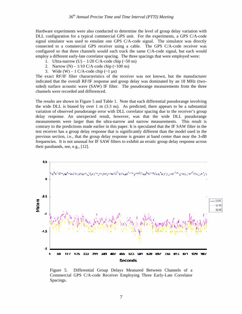
Hardware experiments were also conducted to determine the level of group delay variation with DLL configuration for a typical commercial GPS unit. For the experiments, a GPS C/A-code signal simulator was used to emulate one GPS C/A-code signal. The simulator was directly connected to a commercial GPS receiver using a cable. The GPS C/A-code receiver was configured so that three channels would each track the same C/A-code signal, but each would employ a different early-late correlator spacing. The three spacings that were employed were:
1. Ultra-narrow (U) – 1/20 C/A-code chip (~50 ns) 2. Narrow (N) – 1/10 C/A-code chip (~100 ns) 3. Wide (W) – 1 C/A-code chip (~1 µs)
The exact RF/IF filter characteristics of the receiver was not known, but the manufacturer indicated that the overall RF/IF response and group delay was dominated by an 18 MHz (two-sided) surface acoustic wave (SAW) IF filter. The pseudorange measurements from the three channels were recorded and differenced. The results are shown in Figure 5 and Table 1. Note that each differential pseudorange involving the wide DLL is biased by over 1 m (3.3 ns). As predicted, there appears to be a substantial variation of observed pseudorange error with DLL correlator spacing due to the receiver’s group delay response. An unexpected result, however, was that the wide DLL pseudorange measurements were larger than the ultra-narrow and narrow measurements. This result is contrary to the predictions made earlier in this paper. It is speculated that the IF SAW filter in the test receiver has a group delay response that is significantly different than the model used in the previous section, i.e., that the group delay response is greater at band center than near the 3-dB frequencies. It is not unusual for IF SAW filters to exhibit an erratic group delay response across their passbands, see, e.g., [12].
Figure 5. Differential Group Delays Measured Between Channels of a Commercial GPS C/A-code Receiver Employing Three Early-Late Correlator Spacings.

36th Annual Precise Time and Time Interval (PTTI) Meeting
8

36th Annual Precise Time and Time Interval (PTTI) Meeting
Table 1. Statistics of Differential Group Delays Measurements Mean (m) Standard Deviation (m)
U-N +0.16 0.02 U-W -1.22 0.11 W-N -1.38 0.11
V. SUMMARY AND CONCLUSIONS
This paper has discussed group delays amongst current and future GNSS signals, and in particular group delays that arise as a result of filtering within a GNSS receiver. Simulation and hardware results indicate that group delay differences on the order of several nanoseconds can arise between signals of different modulation types on the same carrier frequency, or for signals of the same type that are processed using different DLL implementations. These effects must be well understood and compensated for by GNSS receiver manufacturers, service providers, and systems engineers, or they could consume unacceptably large portions of the error budgets for a number of high-precision GNSS timing and navigation applications.
VII. DISCLAIMER
The contents of this material reflect the views of the authors. Neither the Department of the Transportation nor the Department of Defense makes any warranty or guarantee, or promise, expressed or implied, concerning the content or accuracy of the views expressed herein.
VIII. ACKNOWLEDGMENTS
The authors would like to thank Pat Fenton of NovAtel for helpful discussions regarding the hardware measurements.
REFERENCES
[1] ARINC, NAVSTAR GPS Space Segment/Navigation User Interfaces, Interface Specification, IS-GPS-200 Revision D, ARINC Engineering Services LLC, El Segundo, California, October 2004.
[2] Yinger, C., W. Feess, R. Di Esposti, A. Chasko, B. Cosentino, D. Syse, B. Wilson, and B. Wheaton, “GPS Satellite Interfrequency Biases,” Proceedings of The Institute of Navigation Annual Meeting, Cambridge, Massachusetts, June 1999.
[3] Rivers, M., “The 2 SOPS User Range Accuracy (URA) Improvement and Broadcast Inter-Frequency Bias (TGD) Updates,” Proceedings of The Institute of Navigation ION GPS 2000, Salt Lake City, Utah, September 2000.
[4] ARINC, NAVSTAR GPS Space Segment/Navigation User Interfaces, Interface Specification, IS-GPS-705, ARINC Engineering Services LLC, El Segundo, California, November 2003.
[5] J. Hahn and E. Powers, 2003, GPS/GALILEO Time Offset: Preliminary Interface Definition, attachment to the Agreement on the Promotion, Provision and Use of Galileo and GPS Satellite-based Navigation Systems and Related Applications, which was signed by
9

36th Annual Precise Time and Time Interval (PTTI) Meeting
representatives of the United States and the member states of the European Union in Dublin, Ireland, on June 26, 2004.
[6] A. Moudrak, A. Konovaltsev, J. Furthner, A. Hornbostel, and J. Hammesfahr, 2004, “GPS Galileo Time Offset: How It Affects Positioning Accuracy and How to Cope with It,” Proceedings of The Institute of Navigation ION GNSS 2004, Long Beach, California, September 2004.
[7] A. Moudrak, J. Furthner, A. Konovaltsev, H. Denks, and J. Hammesfahr, 2004, “Time Dissemination and Synchronization for Galileo Users,” Proceedings of The Institute of Navigation National Technical Meeting, San Diego, California, January 2004.
[8] RTCA Special Committee 159, Minimum Operational Performance Standards for GPS/Wide Area Augmentation System Airborne Equipment, RTCA Document Number 229C, RTCA, Inc., Washington, D.C., November 2001.
[9] Weill, L., “Multipath Mitigation: How Good Can It Get with New Signals?,” GPS World, June 1, 2003.
[10]Hegarty, C., M. Tran, and J. W. Betz, “Multipath Performance of the New GNSS Signals,” Proceedings of The Institute of Navigation National Technical Meeting, San Diego, California, January 2004.
[11]Spilker, J. J., Jr., and D. T. Magill, “The Delay Lock Loop Discriminator – an Optimum Tracking Device,” Proceedings IRE, vol. 49, No. 9, pp. 1403 – 1416, September 1961.
[12]Muller, T., “Performance Degradation in GPS-Receivers Caused by Group Delay Variations of SAW-Filters,” IEEE MTT-S Digest, 1998, pp. 495 – 498.
QUESTIONS AND ANSWERS
10