accu-cal plus instruction booklet - 3d instruments, lp 5/08 page 1 of 20 accu-cal plus instruction...
TRANSCRIPT

KT-0855/08
Page 1 of 20
Accu-Cal Plus Instruction BookletThe“Direct Drive Difference” in Digital
Thank you for choosing the intrinsically safe* Accu-Cal Plus Digital Precision Test Gaugefrom 3D Instruments. The Accu-Cal Plus is very muchlike the 3D Direct Drive Test Gauge; Rugged, accu-rate and easy to use. The Difference is the greateraccuracy possible with a digital display and,through an advanced design, accuracy that is specified to be 0.05% full scale over the temperature range of 0 °C (32 °F) to 50 °C (122 °F).
The large LCD was designed to be reliable and easy to read under a variety ofenvironmental conditions.The Accu-Cal Plus display, complete with a 20 segment bar graph for visual reference, is a five digit display (99999),so auto-ranging is not required to have sufficient display resolution for the rated accuracy.
The silicon chip pressure sensors used are highlyrepeatable over pressure and temperature. Accu-CalPlus sensors incorporate a permanently filled oil isolated stainless steel diaphragm in anall-welded fitting.The only wetted materials are 316 stainless steel.
Other features include the ability to select from up to 23 different pressure units (depending on pressure range), High and Low pressure reading detection, adjustable autoshutdown with 1500 hour battery life (continuous use) on 3 standard alkaline AA batteries,damping, configurable sample rate and password protection of zero and cal data. Thecase is polished 300 series stainless steel and is rated NEMA-4 for weather and corrosionresistance.
And finally,the Accu-Cal Plus is manufactured and serviced by the company that makesTHE Premier Pressure Gauge on the market today. Get The Direct Drive Difference inDigital Today!
* - Intrinsic Safety certification applies to battery powered (Series 75) models only.
INTRODUCTION

PRODUCT INTRODUCTION
KT-0855/08Page 2 of 20
OVERVIEW
The Accu-Cal Plus Digital Precision TestGauge combines the high accuracy of digi-tal electronics with the convenience andease of use of an analog test gauge.Accurate to ± 0.05% FS, the Accu-CalPlus can be used as a calibration refer-ence, or in any application where highaccuracy pressure measurement isrequired.
Many user configurable functions havebeen designed into the Accu-Cal Plusincluding sampling rate, TARE, damping,auto shut off, and Max/Min. Once thegauge is configured, settings can belocked and password protected to preventunauthorized changes to configuration.
UNPACKING
Check to see that your Accu-Cal Plus hasarrived intact. Batteries are factoryinstalled unless you have purchased theoptional 24V powered version, in whichcase batteries and power adapter are notsupplied or installed. Save the packingmaterials at least until you have verifiedthat there is no concealed damage.
HAZARD LOCATION INFORMATION
Ex Hazardous AreasAn ex-hazardous area as used in this manu-al refers to an area made hazardous by thepotential presence of flammable or explo-sive vapors. These areas are also referredto as hazardous locations, see NFPA 70Article 500 or CSA C22.1 Section 18.
CertificationThis product is certified by CSA with thefollowing rating: Class I, Div. 2, Groups A-D
MisuseShould the Accu-Cal Plus be exposed tooverpressure or sudden physical shock(i.e. being dropped) it should be examinedfor any damage that may cause a safetyconcern. If in doubt please return unit forevaluation to 3D Instruments. Please referto the Warranty section on page 19 forcompany contact information.
CAUTIONTo avoid possible damage to the gaugeor to equipment under test:
• If the LCD displays “OL”, then the pres-sure range limit has been exceeded andthe pressure source must immediatelybe removed from the Accu-Cal Plus toprevent damage to the pressure trans-ducer.
• Maximum torque allowed is 13,5 Nm =10 ftlbs. NEVER exceed the allowabletorque.
INSTALLATION
Prior to installing the gage into a processconnection, please ensure all pressure isvented from the system. Ensure that youuse proper fittings to mate with the gauge.Failure to utilize proper fittings will result inleaks. Never attempt to tighten the unit byturning the gauge housing by hand. Thismay result in permanent damage to thisgauge.
USC
R

KT-0855/08
Page 3 of 20
ACCU-CAL PLUS DISPLAYS AND CONTROLS
Turns Power on/offwhen held down for 2 seconds
Enters set-up andconfiguration menus
Zeros the display,Scrolls forwardthrough menu displays
Recalls Max/Minreadings. Scrollsbackwards throughmenu displays
Pressure display
Engineering Units
0 - 100% bar graph
Selects an action in configuration. Also turns the back-lighton/off
OPERATING INSTRUCTIONS
PRODUCT INTRODUCTION
UNIT POWER-UP
The standard Accu-Cal Plus is suppliedwith 3 AA batteries installed. If you pur-chased the optional 24Volt powered ver-sion, batteries are not installed. Connect a24V power supply to the terminal block onthe rear of the gauge noting properpolarity - refer to page 6 for detailedinstructions and warnings.
Push and hold down the POWER key for 2- 3 seconds to turn the unit on. The LCDwill briefly display the firmware version,test the bar graph display segments andthen cycle to the “normal operation”screen. The gauge is now ready for serv-ice. To turn off the gauge, press and holdthe POWER key.
Note: The gauge will read to 120% of fullscale. After that point, the gauge will dis-play: OL (over limit). The gauge is onlycalibrated to 100% of full scale.
SET-UP AND CONFIGURATION
Push the CONFIG key to access the user-settable functions on the gauge. Each timethe CONFIG key is pressed, the displayadvances to the next function. Once afunction has been set, press ENTER toexit the configuration menu, or CONFIG tocontinue with further configuration. Insequential order, the configuration menuand operation is as follows:
1. Set Engineering Units (Default = PSI)The unit is shipped configured to dis-play PSI. By pressing the ▲ and ▼(ZERO and MAX/MIN) keys you canscroll forward and backwards throughthe available engineering units includinga custom unit. When the desired unit isdisplayed, press ENTER. Pressure willnow be displayed in the chosen engi-neering units. Refer to pages 16 and 17of this manual for a list of availableengineering units. See the SupervisoryMode section for details on setting upcustom units.
KT-0855/08Page 4 of 20
2. Set Auto Off (Default = 30 minutes)The auto shut-off can be set in 1minute increments from 1 to 30 min-utes or “off” (continuous operation).Use the ▲ and ▼ keys to set thedesired interval. The “off” setting is atthe low end of the choices, below 1minute. With the auto shut-off off, it willremain on until manually switched off.
3. Display Battery VoltageDisplays actual voltage of battery“pack” and a “percent of life” bargraphindicating battery condition.
4. Display Actual TemperatureA PN junction based temperature sen-sor is built into the microprocessor,which is mounted on the PC board. Itcan accurately read the temperatureinside the gauge case. The value canbe set to °F or °C using the ▲ and ▼keys. The factory default value is °C.
5. Set Damping (Default = OFF)Choices are “on” and “off” set with the▲ and ▼ keys. Turning damping on willsmooth readings from pulsating pres-sure sources. The Damping functionaverages 10 successive measure-ments prior to updating the LCD dis-play and MAX/MIN registers.
6. Set Sample Rate (Default = 10/sec)This determines how often pressure issampled and both the display andMAX/MIN registers are updated.Choices are 0.5, 1, 3, and 10 sam-ples/second with 10/sec being fastest.
7. Set TAREThis function allows you to build in aconstant offset value, which is thensubtracted from the measured pres-sure. Example: if a TARE is set at 30PSI and the measured pressure is 37PSI, the displayed value will be 7 PSI. A pressure of 27 PSI would be dis-played as –3 PSI. TARE is settableacross the entire span of the gauge.
The TARE value is set manually withthe ▲ and ▼ keys, and is based on theengineering units and resolution select-ed for display. TARE value can be setto the maximum range of the gauge.
Note: The bar graph will always displaythe actual pressure based on the fullrange of the gauge regardless of theTARE setting. This is done for safety toinsure that even with a “0” reading thatpressure is being applied to the gauge.
8. FUnC LockAccess to each of the settable parame-ters above can be turned “off” onceset, to prevent unauthorized changesto configuration. This is accomplishedthrough a password protected “supervi-sory mode”. This function is accessedthrough the Configuration menu - referto the next section.
SUPERVISORY MODE
Press the ENTER key when “FUnC LOCK”is displayed, 0 PWRD will be displayed onthe gauge display. The password to enterthe supervisory mode is 101, set using the▲ and ▼ keys. Holding a key continuouslywill cause the display to advance quickerfor faster setting. Press the ENTER key toreach the supervisory mode. Note: The password is factory set andcannot be changed.
1. The Accu-Cal Plus is shipped from thefactory with all accessible settings“unlocked” or available to be changed.
2. In order, the functions that can beunlocked, locked or accessed are:• Zero function (enable/disable)• Change pressure units
(enable/disable)• Auto shutdown adjustment
(enable/disable)• Damping settings (enable/disable)• Sample rate setting (enable/disable)• TARE setting (enable/disable)• Custom engr. units (set scale factor)
OPERATING INSTRUCTIONS

KT-0855/08
Page 5 of 20
OPERATING INSTRUCTIONS
3. In supervisory mode each of theparameters can be locked or unlockedindividually using the ▲ and ▼ keys.Select LOC (lock) for those parametersyou do not want to be accessible, andUnLOC (unlock) for those that can beaccessed.
4. Use the CONFIG key to scroll throughthe above choices, and the ▲ and ▼keys to lock and unlock features. PressCONFIG to continue scrolling throughthe parameters, pressing ENTER atany point saves your settings andreturns the gauge to normal operation.When a function is “locked, it cannotbe accessed or changed from its cur-rent state. To change a locked function,enter the supervisory mode, andunlock the function. Once it ischanged, you may enter supervisorymode to lock access again.
5. Setting a custom engineering unit orscale: The last menu choice in supervi-sory mode is SET FACTR. This allowsyou to set a multiplier factor from 0.001to 100, creating a custom scale. Theset factor will be multiplied by the PSImeasured, the result will be displayed.By setting a factor of 25, a 40 PSIpressure would display as 1000 (40 x25). The engr. unit displayed on theAccu-Cal Plus will be “Cust”.
NORMAL OPERATION
Backlight OperationPress the ENTER key to enable the back-light. Press the ENTER key to turn it off.
Zeroing the GaugePress and hold the ZERO key for 1 - 2seconds until the word HOLD disappearsfrom the LCD.
Note: For Absolute sensor versions of thegauge pressing the ZERO key will promptthe user to enter a barometric referencepressure. Use the ▲ and ▼ arrow to adjustthe reading as required. Then press ENTER.
Failure to depress the ZERO key until theword HOLD disappears will result in thegauge not being re-zeroed. To ensureaccurate measurements, the extent ofunit zero adjustment is apprx. ± 5% offull scale.
Note: The gauge should always be re-zeroed immediately before measurementsare taken. The zero will fluctuate until thetemperature is stable. This will be morenoticeable on low pressure ranges. If thegauge can not be zeroed, contact factory.
MAX/MIN FunctionThe Accu-Cal Plus stores minimum andmaximum pressure values in memory.Pressing the MAX/MIN key once will dis-play the maximum pressure stored in mem-ory. Pressing the MAX/MIN key again willdisplay the minimum pressure stored inmemory. Press the MAX/MIN key again toreturn to normal (live display) operation. Toclear the MAX/MIN memory registers,press and hold the MAX/MIN key for 2 ormore seconds until “CLr” is displayed. If avalue of “OL” (over limit) appears in theMAX register, this indicates that the gaugeexperienced pressure above 120% of span.
Note: The rate of MAX/MIN registerupdates is determined by sample rate andvalues will be lost when the unit is shut off.
Analog Bar GraphThe 20 segment analog bar graph locatedat the bottom of the LCD display indicatesthe applied pressure level expressed as apercentage of the full range of the gauge.
Note: If a TARE value has been pro-grammed into the gauge, the numericvalue indicated on the LCD display willnot reflect the true pressure being appliedto the gauge.

KT-0855/08Page 6 of 20
Battery LifeBattery life is approximately 1500 hours(60 days) of continuous use with the back-light off and at a sample rate of 3/sec. Withintermittent use, batteries could last a yearor more. There is a “low battery” icon inthe upper left of the display. It will appearwhen battery level is low at approximately3.3 volts. The unit will shut itself off whenthe battery voltage drops to 3.0 volts.Replace batteries per recommendationsfound in the next section of this manual.
Changing the Batteries
WARNINGExplosion hazard
Batteries must only be changed in an areaknown to be non-hazardous.
Grasp the face ring on the Accu-Cal Plus,turn it approximately 1⁄4 turn counterclock-wise and remove. The face of the gaugecan now be lifted to expose the batteryholder. Install three AA batteries notingproper polarity. Reassemble the case mak-ing certain that the face is properly oriented.
RS-232 Interface (optional)A RS-232 interface is provided standard onthe Accu-Cal Plus. Serial communicationcan be used for configuration, calibration,and to transfer measurement data from thegauge. An optional RS-232 communicationcable is required for this operation and canbe obtained from the factory. For informa-tion on the optional RS-232 cable andrequired software communication protocol,refer to pages 9 -11.
WARNINGThe RS-232 interface must not be used in
hazardous areas.
24 VDC Power Version (optional)If you purchased the optional 24 Volt ver-sion, the terminals for power input arelocated on the rear of the gauge. To applypower simply connect a 24 volt source tothe rear terminal block taking care toobserve proper polarity. Refer to page 18.
WARNINGGauges ordered with the external poweroption will not come with batteries orpower adapter installed. Batteries MUSTNOT be installed when operating on exter-nal power. External power option gaugesare not approved for hazardous locationuse. The use of batteries in connection witha power adapter can cause batteries toleak or explode, thereby damaging theelectronics and voiding the warranty.
If you lack a 24 VDC power source, topower the unit, one may be obtained from3D Instruments - contact factory for detailsor refer to page 13 for ordering informa-tion.
The 24 volt version can be operated on 3 x AA batteries provided the unit is notalready being powered by a 24 volt source.If the gauge is currently hooked to a 24volt source, disconnect it and install thebatteries per the instructions outlined in the“Changing the Batteries” section.
Mounting (optional)An optional front or rear 300 SeriesStainless Steel mounting flange, which iswelded to the case, is available for theAccu-Cal Plus. Outline drawings for bothflanged versions are provided on page 12.
OPERATING INSTRUCTIONS

OverviewVerification and calibration of the Accu-CalPlus (ACP) is not required on newly sup-plied units, only when the accuracy is sus-pect. Unit re-calibration requires pressureand/or vacuum standards able to produceand indicate pressures from vacuum to thefull-scale range of the unit under test. Inorder to maintain the specified accuracy ofthe ACP, calibration standards used to re-cal the ACP must have 4x better accuracythan the ACP. A vacuum standard will berequired for the calibration of the followingranges: high accuracy vacuum, 100, 300,and 500 psi ranges.
Calibration adjustment of the ACP is per-formed electronically via internal softwarewith the case closed. All calibration com-mands and adjustments are done via thekeypad, using the display to prompt theuser through the calibration process.
Nine or ten calibration points are used inthe adjustment program, working from fullscale to zero at pressures equaling 100%,87.5%, 75%, 62.5%, 50%, 37. 5%, 25%,12.5%, and 0% of full scale plus a possiblevacuum point.Note: This is an ambient temperature cali-bration and should be performed at anambient temperature of 23 ºC ± 3 ºC (72ºF ± 5 ºF). Calibration outside this temper-ature range will invalidate the temperaturecompensation program.
Calibration IntervalYou should check performance of thegauge at the interval required by your cali-bration program. We recommend adjust-ment when measurement deviates bymore than 75% of the specified accuracy.
ConnectionsThe Accu-Cal Plus has a 1/4” NPT malepressure input port. Various adapters mayor may not be needed to connect to thepressure standard. Always ensure thehose, tubing, and fittings etc have a ratedworking pressure at or above the pressureof the unit.
Entering Calibration ModeAfter you have made your connections,turn the power on while holding the CONFIG key. Use the arrow keys to enterthe password. The password is: 101. If youhave entered the calibration mode correct-ly, the display should look as shown below.The pressure value displayed will be thefull-scale value of the gauge. Refer toimportant note on bottom of page 8.
Screens shown in this manual representthe displays shown with a 500 psi gauge.The Accu-Cal Plus will prompt the techni-cian for the appropriate pressure at eachcalibration point.
Use the Pressure Standard to output500.00 psi (100%). After the output hasstabilized, press the ENTER key to contin-ue. As the unit takes readings, the screenwill show -------. When the readings arecomplete, the screen should look asshown below.
Use the Pressure Standard to output437.50 psi (87.5%). After the output hasstabilized, press the ENTER key to contin-ue. As the unit takes readings, the screenwill show -------. When the readings arecomplete, the screen should look asshown below.
Use the Pressure Standard to output375.00 psi (75%). After the output has sta-bilized, press the ENTER key to continue.As the unit takes readings, the screen willshow -------. When the readings are done,the screen should look as shown below.
KT-0855/08
Page 7 of 20
PSI500.00
CAL MODE
PSI437.50
CAL MODE
ACCU-CAL PLUS CALIBRATION PROCEDURE
PSI375.00
CAL MODE

Use the Pressure Standard to output312.50 psi (62.5%). After the output hasstabilized, press the ENTER key to contin-ue. As the unit takes readings, the screenwill show -------. When the readings arecomplete, the screen should look asshown below.
Use the Pressure Standard to output250.00 psi (50%). After the output has sta-bilized, press the ENTER key to continue.As the unit takes readings, the screen willshow -------. When the readings are com-plete, the screen should look as shownbelow.
Use the Pressure Standard to output187.50 psi (37.5%). After the output hasstabilized, press the ENTER key to contin-ue. As the unit takes readings, the screenwill show -------. When the readings arecomplete, the screen should look asshown below.
Use the Pressure Standard to output125.00 psi (25%). After the output has sta-bilized, press the ENTER key to continue.As the unit takes readings, the screen willshow -------. When the readings are com-plete, the screen should look as shownbelow.
Use the Pressure Standard to output 62.50psi (12.5%). After the output has stabilized,press the ENTER key to continue. As theunit takes readings, the screen will show -------. When the readings are complete,the screen should look as shown below.
Use the Pressure Standard to output 0.00psi. After the output has stabilized, pressthe ENTER key to continue. As the unittakes readings, the screen will show -------.When the readings are complete, thescreen should look as shown below.
Note: Only some of the pressure rangesfor the Accu-Cal Plus will require a vac-uum point as part of the calibration rou-tine. If your gauge is not one of those,then this step will be automatically skippedand the calibration routine will be com-plete. Use the Pressure Standard to output -12.00 psi. After the output has stabilized,press the ENTER key to continue. As theunit takes readings, the screen will show -------. When the procedure is complete,the unit will update the calibration datapoint. The gauge will then automaticallyshut off and repower itself into the normaloperating mode.
Note: In the calibration routine, if anentry is misentered there is no way tocorrect the value - either complete thecalibration step and reenter the propervalue or turn the gauge off at this pointand repeat the entire calibration. If thecalibration routine is aborted prior to itscompletion, none of the newly enteredcal points will be saved.
KT-0855/08Page 8 of 20
PSI187.50
CAL MODE
PSI125.00
CAL MODE
PSI62.50
CAL MODE
PSI0.00
CAL MODE
PSI312.50
CAL MODE
PSI250.00
CAL MODE
PSI-12.00
CAL MODE
ACCU-CAL PLUS CALIBRATION PROCEDURE

Enclosed are instructions for establish-ing communications between the Accu-Cal Plus Digital Test Gauge (Version1.08/later) and a personal computer(PC) utilizing the Hyper Terminal com-munications software included in theWindows xP Operating System. A cus-tom cable assembly (3D InstrumentsPart Number: 2025-0004) is required tocomplete the link-up.
To set up remote operation of the gaugevia the Windows Hyper Terminal program,first connect the gauge, via the specialcale, to a COM serial communications porton the PC. The following procedure detailshow to set up the Hyper Terminal programto allow bi-directional communicationbetween the Accu-Cal Plus and the PC.
1. Start the Hyper Terminal program …click on: All Programs/Accessories/Communications/Hyper Terminal.
2. In the “CONNECTION DESCRIPTION”box, enter a name for your communi-cation routine (i.e.: Accu-Cal Plus) andthen click: OK
3. In the “CONNECT TO” box, under“Connect Using”, choose the appropri-ate serial port on the PC to which thegauge is connected (i.e.: com1) andthen click: OK
4. In the “XXX PROPERTIES” box (whereXXX = serial port selection in #3above), under “port settings”, enter thefollowing serial port settings:
A) Bits Per Second: 9600B) Data Bits: 8C) Parity: NoneD) Stop Bits: 1E) Flow Control Xon/Xoff
click: OK
5. At this point, the “HYPERTERMINAL”box will appear. Click on: FILE andthen: PROPERTIES … the “YYYPROPERTIES” box (where YYY=nameassigned to the communications rou-
tine in #2 above) appears. Click on:SETTINGS and then click on” ASCIISETUP. A box titled “ASCII SETUP”appears … check the following items:A) In the “ASCII Sending” section:
Send line ends with line feeds.B) In the “ASCII Sending” section:
Echo typed characters locally.C) In the “ASCII Receiving” section:
Append line feeds to incoming lineends
Note: In the “ASCII Receiving” section,the line “wrap lines that exceed termi-nal width” should already be checked.
Click: OK
6. Click: OK to exit this box.
The gauge is sent from the factory inthe “query” mode … meaning that theinformation is supplied in response to agiven after a query. Refer to the List ofQuery Commands in Table 1 on Page 10for information on commands. These com-mands can be used after you have estab-lished communication with the gauge. TheAccu-Cal Plus can also be configured totransmit this information in a “streaming”mode, whereby lines of data are sent auto-matically to the PC. Once communicationwith the gauge is established, type in thecommand: stream_on and press theENTER key. The gauge is now in the“streaming” mode.
Note: This setting will now be saved innon-volatile memory as the default modeof RS-232 communication.
The displayed information, when the gaugeis in the “streaming” mode, will appear inthe form:
A, B CC.C, D
Example: 0, PSI 24.4 Celwhere: A = pressure reading, B = Engineering Unit selected for pressurereading, CC.C = temperature reading andD = unit of temperature measurement.
KT-0855/08
Page 9 of 20
ACCU-CAL PLUS RS-232 COMMUNICATION

The following are general notes on RS-232communication with the Accu-Cal Plus:
1. The rate of screen updates in the“streaming” mode is governed by thesample rate of the Accu-Cal Plus.Consult page 4 of the InstructionManual for details on changing thisvalue.
2. Data collected during a communicationsession can be stored and retrieved. Atthe end of your data collection period,type: FILE and SAVE AS. A programlike EXCEL or other database pro-grams can import and manipulate thesaved ASCII information.
KT-0855/08Page 10 of 20
ACCU-CAL PLUS RS-232 COMMUNICATION
Table 1 is a list of available commands to which the Accu-Cal Plus Digital Test Gauge willrespond. Please note: the commands must be entered exactly as they are listed. Both upper andlower case letters and symbols are acceptable.
Table 1 List of Query CommandsCommand DescriptionCAL_START Puts the Accu-Cal Plus in calibration mode*CLS Clears the error queueFAULT? Returns an error code from the error queue*IDN? Identification query. (Returns 3D/Model?Firmware revision level)TARE Tares the offset pressure of the reading on the gaugeTARE? Returns the current tare valuePRES_UNIT? Returns the pressure Engr. Unit - refer to Table 2 belowPRES_UNIT Sets the pressure unit for the display - refer to Table 2 belowZERO_MEAS Re-zeros the gauge (same result as pressing the “ZERO” keyZERO_MEAS? Returns the current zero offset valueMINMAX_RST Resets the minimum and maximum recorded valuesMIN? Returns the minimum recorded valueMAX? Returns the maximum recorded valueHC_OFF Turns unit offTEMP? Returns temperature in the chosen unitsHC_SI_OFF Disables SI modeHC_SI_ON Enables SI mode (SI enables only: kPa, MPa, Bar, mBar units)CAL_STORE Stores calibration dataHC_AUTO_OFF Disables auto shutdownHC_AUTO_ON Enables auto shutdownCUST_MULT? Sets the multiplier for the custom unit typeSTREAM_OFF Disables “streaming” dataSTREAM_ON Enables “streaming” dataVAL? Returns the measured pressure value in selected units.HC_CMD_LIST Prints out a command listTEMP_UNIT Used to set temperature unitTEMP_UNIT? Returns temperature unitCommand examples:1) Pres_unit bar Sets engineering unit to Bar2) Temp_unit far Sets temperature unit to fahrenheit
KT-0855/08
Page 11 of 20
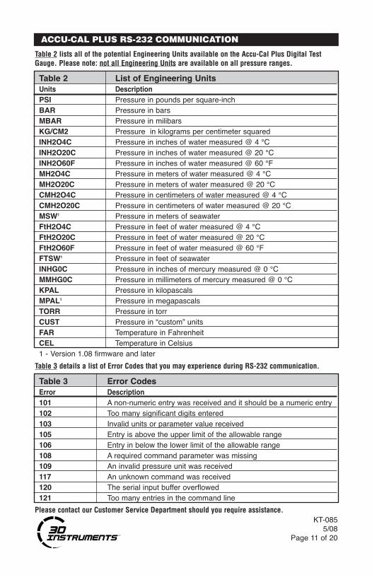
Table 2 lists all of the potential Engineering Units available on the Accu-Cal Plus Digital TestGauge. Please note: not all Engineering Units are available on all pressure ranges.
Table 3 details a list of Error Codes that you may experience during RS-232 communication.
Please contact our Customer Service Department should you require assistance.
Table 2 List of Engineering UnitsUnits DescriptionPSI Pressure in pounds per square-inchBAR Pressure in barsMBAR Pressure in milibarsKG/CM2 Pressure in kilograms per centimeter squaredINH2O4C Pressure in inches of water measured @ 4 °CINH2O20C Pressure in inches of water measured @ 20 °CINH2O60F Pressure in inches of water measured @ 60 °FMH2O4C Pressure in meters of water measured @ 4 °CMH2O20C Pressure in meters of water measured @ 20 °CCMH2O4C Pressure in centimeters of water measured @ 4 °CCMH2O20C Pressure in centimeters of water measured @ 20 °CMSW1 Pressure in meters of seawaterFtH2O4C Pressure in feet of water measured @ 4 °CFtH2O20C Pressure in feet of water measured @ 20 °CFtH2O60F Pressure in feet of water measured @ 60 °FFTSW1 Pressure in feet of seawaterINHG0C Pressure in inches of mercury measured @ 0 °CMMHG0C Pressure in millimeters of mercury measured @ 0 °CKPAL Pressure in kilopascalsMPAL1 Pressure in megapascalsTORR Pressure in torrCUST Pressure in “custom” unitsFAR Temperature in FahrenheitCEL Temperature in Celsius1 - Version 1.08 firmware and later
Table 3 Error CodesError Description101 A non-numeric entry was received and it should be a numeric entry102 Too many significant digits entered103 Invalid units or parameter value received105 Entry is above the upper limit of the allowable range106 Entry in below the lower limit of the allowable range108 A required command parameter was missing109 An invalid pressure unit was received117 An unknown command was received120 The serial input buffer overflowed121 Too many entries in the command line
ACCU-CAL PLUS RS-232 COMMUNICATION

KT-0855/08Page 12 of 20
120°
ø5.88
ø5.375 ø.233X
Front FlangeVersion
SIDE VIEW
FRONT VIEW
2.05
BackFlangeVersion
FrontFlange
Version
1.90
.81
ø4.35
1.27
3.27
1.22
.57 1/4 NPT
(Both front view and side view pictured with optional mounting flange)All dimensions in inches.
ACCU-CAL PLUS OUTLINE DRAWINGS

KT-0855/08
Page 13 of 20
1 2 3 4 5
PART NUMBER: XXXXX - XX B XX XXX
Example: 75514-33B55 Battery Powered Accu-Cal Plus with 300 series SS case3000 psig sensor, bottom 1/4" NPT male fitting, without mounting flange
1 Product Description:75514 - Accu-Cal Plus: 3 x AA battery powered version,76514 - Accu-Cal Plus: 24 VDC version
(does NOT include 24 volt adapter or batteries)75114 - High Accuracy Vacuum Accu-Cal Plus: 3 x AA battery power version76114 - High Accuracy Vacuum Accu-Cal Plus: 24 VDC version
(does NOT include 24 volt adapter or batteries)2 Pressure Ranges Codes: (all psig ranges include vacuum measurement)
04: -1-0-1 psig48: -14.7-0-30 psig*(Vac) 26: -14.5-0-300 psig 33: -14.5-0-3,000 psig15: -5-0-15 psig 27: -14.5-0-500 psig 35: -14.5-0-5,000 psig21: -5-0-30 psig 29: -14.5-0-1,000 psig 38: -14-0-10,000 psig23: -14.5-0-100 psig 32: -14.5-0-2,000 psig 72: 0-15 psia73: 0-30 psia 75: 0-100 psia 77: 0-300 psia*Product description (Item #1) for this range to be either: 75114 or 76114
3 Process Connection:B: 1/4" NPT male
4 Connection Position and Mounting Flange Codes:15: Flange front, bottom fitting 45: Flange back, back fitting*25: Flange front, back fitting 55: Flange none, bottom fitting35: Flange back, bottom fitting* 65: Flange none, back fitting* Codes 35 and 45 not available on 76114 and 76514 series.
5 Option Codes: (leave blank if no options are required)PNO: Accu-Cal Plus Cal Kit #1–includes an Accu-Cal Plus digital gauge,
Model 8110-300: 0-300 psi Pneumatic Handpump, Hose Kit andSeries-200 ABS waterproof case
PRO: Accu-Cal Plus Cal Kit #2–includes an Accu-Cal Plus digital gauge,Model 8111-300: Vac/0-300 psi Duplex Handpump, Hose Kit andSeries-200 ABS waterproof case
PUO: Accu-Cal Plus Cal Kit #3–includes an Accu-Cal Plus digital gauge,Model 8112-3000: 0-3000 psi Hydraulic Handpump, Hose Kit andSeries-200 ABS waterproof case
GCO1: Calibration Certificate Level #1 - readings done in descending pressureat room temperature
GCO2: Calibration Certificate Level #2 - readings in both ascending anddescending pressures at room temperature
GCO3: Calibration Certificate Level #3 - readings in both ascending anddescending pressures done at three distinct temperatures...typically:22°C, 5°C and 45°C.
6 Accessories: • Custom RS-232 Cable - Part Number: 2025-0004• 110 VAC to 24 VDC power adapter wall mount style; 6 foot cable -
Part Number: 2001-0090• Rubber boot for gauge - Part Number: 2023-0005
(Boot fits ONLY - No Flange, Bottom Fitting, Battery Powered models)
ACCU-CAL PLUS MODEL NUMBERING SYSTEM

KT-0855/08Page 14 of 20
All specifications cover the temperaturerange from 0° C to +50° C, unless other-wise noted.
Available Pressure RangesSee pages 16 and 17 for tables of avail-able ranges in PSI plus equivalent rangesand resolution for all Engineering Units.
Accuracy0-1 psi: 0.1% of Full Scale for both vacu-um and positive pressureAll other positive pressure ranges >1 psi:0.05% of Full ScaleVacuum: ±0.25% FS* (500 PSI pressurerange and below); 2% FS accuracy forranges above 500 PSI.
*High accuracy vacuum - series 75114 and76114 - vacuum accuracy is: ±0.05% FS,where FS = 30 PSI
All accuracies include all effects due to:hysteresis, repeatability, non-linearityand temperature.
Temperature Compensation0 °C to +50 °C (32 °F to +122 °F) to ratedaccuracy
Over Pressure ProtectionProof Pressures for the various pressuresensors are detailed on pages 16 and 17.Burst Pressures for the various pressuresensors are as follows:
Range Pressure (PSI)0-1 500-15** 5000-30*, ** 5000-100** 10000-300** 20000-500 20000-1000 100000-2000 100000-3000 100000-5000 100000-10000 15000
*including series 75114/76114 high accura-cy vacuum gauges** - 15, 30, 100 and 300 psia same as psigversions
Standard Engineering Units*PSI, Bar, mBar, kPa, kg/cm2, inH2O (4 °C, 20 °C or 60 °F),ftH2O (4 °C, 20 °C or 60 °F), mmH2O (4 °C and 20 °C),cmH2O (4 °C and 20 °C), mH2O (4 °C and 20 °C), inHg, mmHg, Torr, MPa, ftSw and mSw One custom unit (user programmable)* Not all units available for all ranges.
Materials of ConstructionCase: 300 Series Stainless SteelWetted Parts: Refer to sensor sectionOverlay: PolycarbonateSensor bracket: Nickel plated brassBoot (optional): Synerflex
SensorsAll ranges other than high accuracy vacu-um: piezoresistive semiconductor sensorchip in an oil isolated housing incorporat-ing a 316 SS isolation diaphragm. Mediacompatibility: liquids and gases compatiblewith 316 SS.
0-1 psig and high accuracy vacuum:piezoresistive silicon with wetted materialsof - silicon, RTV, gold and glass. Mediacompatibility: non-corrosive gases.
EnvironmentalOperating: -10 °C to +55 °C (14 °F - 131 °F)Storage: -20 °C to +70 °C (- 4 °F to +158 °F)Rel. Humidity: 10 to 95% non condensing
MechanicalDimensions: 5.39" (height) x 4.355" (diameter) x 1.95" (depth)Pressure Connection: 1⁄4” NPT MaleHousing: 300 Series Stainless Steel, qualifies as NEMA 4/ IP65 waterproof Weight: 1.09 lbs (495 gms)
SPECIFICATIONS

KT-0855/08
Page 15 of 20
LCD DisplayDigits: 5, 0.65" (16.53 mm) highBar graph: 20 segment, 0 to 100% FSBacklight: Fiber optic
PowerBattery: three (3) AA alkaline batteries,optional 24 VDC powerBattery Life: 1,500 hours without backlight@ 3/sec sample rate2,000 hours at slow sample rate“Low Battery” indicator icon is displayednear the end of battery lifeAuto shutoff: adjustable from 1 - 30 mins
Agency ApprovalsCE Mark
EN 55022: 1998 and EN 61000-4-2/3: 1995Meets EMI/RFI and ESD conditions out-lined in above EN standards: 30 mHz to 1 gHz with a field strength of 3 v/m.
Intrinsic SafetyThe battery powered version of the Accu-Cal Plus (Series 75514 and 75114) con-forms with all requirements for Class 1,Division 2, Groups A, B, C and D haz-ardous area locations. Specific approvalsare as follows:
CSA - USA and Canada Approvals
USC
R
SPECIFICATIONS

KT-0855/08Page 16 of 20
PRESSURE RANGES / DISPLAY RESOLUTIONS
Pressure Range PSI Conversion 1 15(1, 3) 30(*, 2, 3) 100(3) 300(3)
Unit/Proof Pressure PSI Factor 5 30 60 200 600
psi 1.0000 1.0000 15.000 30.000 100.00 300.00
bar 0.06894757 0.0689 1.0342 2.0684 6.8948 20.684
mbar 68.94757 68.948 1034.2 2068.4 6894.8 20684
kPa 6.894757 6.8948 103.42 206.84 689.48 2068.4
MPa 0.0068947 0.0069 0.1034 0.2068 0.6895 2.0684
ftSw 2.2470 2.2470 33.705 67.410 224.70 674.10
mSw 0.6849 0.6849 10.274 20.547 68.490 205.47
kg/cm2 0.07030697 0.0703 1.0546 2.1092 7.0307 21.092
mmH2O@4°C 703.089 703.09 10546 21093 70309 NA
mmH2O@20°C 704.336 704.34 10565 21130 70434 NA
cmH2O@4°C 70.3089 70.309 1054.6 2109.3 7030.9 21093
cmH2O@20°C 70.4336 70.434 1056.5 2113.0 7043.4 21130
mH2O@4°C 0.703089 0.7031 10.546 21.093 70.309 210.93
mH2O@20°C 0.704336 0.7043 10.565 21.130 70.434 211.30
inH2O@4°C 27.68067 27.681 415.21 830.42 2768.1 8304.2
inH2O@20°C 27.72977 27.730 415.95 831.89 2773.0 8318.9
inH2O@60°F 27.70759 27.708 415.61 831.23 2770.8 8312.3
mmHg@0°C 51.71508 51.715 775.73 1551.5 5171.5 15515
inHg@0°C 2.03602 2.0360 30.540 61.081 203.60 610.81
ftH2O@4°C 2.306726 2.3067 34.601 69.202 230.67 692.02
ftH2O@20°C 2.310814 2.3108 34.662 69.324 231.08 693.24
ftH2O@60°F 2.308966 2.3090 34.634 69.269 230.90 692.69
Torr 51.71508 51.715 775.73 1551.5 5171.5 15515Proof Pressure - maximum allowable pressure without a shift in calibration.
*including 75114/76114 series high accuracy vacuum gauges
Notes:
(1) Also applies to: -5 to +15 psig range
(2) Also applies to: -5 to +30 psig range
(3) PSIA sensors have same values.
KT-0855/08
Page 17 of 20
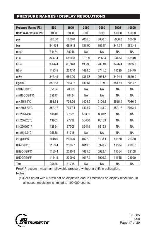
PRESSURE RANGES / DISPLAY RESOLUTIONS
Pressure Range PSI 500 1000 2000 3000 5000 10000
Unit/Proof Pressure PSI 1000 2000 3000 6000 10000 15000
psi 500.00 1000.0 2000.0 3000.0 5000.0 10000
bar 34.474 68.948 137.90 206.84 344.74 689.48
mbar 34474 68948 NA NA NA NA
kPa 3447.4 6894.8 13790 20684 34474 68948
MPa 3.4474 6.8948 13.790 20.684 34.474 68.948
ftSw 1123.5 2247.0 4494.0 6741.0 11235 22470
mSw 342.45 684.90 1369.8 2054.7 3424.5 6849.0
kg/cm2 35.153 70.307 140.61 210.92 351.53 703.07
cmH2O@4°C 35154 70309 NA NA NA NA
cmH2O@20°C 35217 70434 NA NA NA NA
mH2O@4°C 351.54 703.09 1406.2 2109.3 3515.4 7030.9
mH2O@20°C 352.17 704.34 1408.7 2113.0 3521.7 7043.4
inH2O@4°C 13840 27681 55361 83042 NA NA
inH2O@20°C 13865 27730 55460 83189 NA NA
inH2O@60°F 13854 27708 55415 83123 NA NA
mmHg@0°C 25858 51715 NA NA NA NA
inHg@0°C 1018.0 2036.0 4072.0 6108.1 10180 20360
ftH2O@4°C 1153.4 2306.7 4613.5 6920.2 11534 23067
ftH2O@20°C 1155.4 2310.8 4621.6 6932.4 11554 23108
ftH2O@60°F 1154.5 2309.0 4617.9 6926.9 11545 23090
Torr 25858 51715 NA NA NA NAProof Pressure - maximum allowable pressure without a shift in calibration.
Notes:
(1) Cells noted with NA will not be displayed due to limitations on display resolution. In
all cases, resolution is limited to 100,000 counts.

KT-0855/08Page 18 of 20
24V TERMINAL (76 SERIES ONLY)
IDENTIFICATION LABEL
RS-232 ACCESS PORT(BLOW OUT PLUG)
3 D I n s t r u m e n t s , L P 2900 E. White Star Avenue Anaheim, CA 92806Ph: (714) 399-9200
Pressure Range: 3000 PSIP/N: 755P4-33B55 S/N: AC-XXXXXXX
Dissassembly, Misuse or Negligence Voids Warranty
(Pictured with optional mounting flange)
ACCU-CAL PLUS 24VDC WIRING DETAIL

3D Instruments, LP warrants the Accu-Cal Plus to be free from defects in material andworkmanship under normal use and service for one (1) year from date of purchase to theoriginal purchaser. It does not apply to batteries or when the product has been misused,altered or damaged by accident or abnormal conditions of operation.
Within one (1) year from date of purchase, 3D Instruments will, at our option, repair orreplace a defective device free of charge and the device will be returned, transportationprepaid. However, if we determine the failure was caused by misuse, alteration, accidentor abnormal condition of operation, you will be billed for the repair.
3D INSTRUMENTS, LP MAKES NO WARRANTY OTHER THAN THE LIMITED WAR-RANTY STATED ABOVE. ALL WARRANTIES, INCLUDING IMPLIED WARRANTIESOF MERCHANTABILITY OR FITNESS FOR ANY PARTICULAR PURPOSE, ARE LIMIT-ED TO A PERIOD OF ONE (1) YEAR FROM THE DATE OF PURCHASE. 3D INSTRU-MENTS, LLC SHALL NOT BE LIABLE FOR ANY SPECIAL, INCIDENTAL OR CONSE-QUENTIAL DAMAGES, WHETHER IN CONTRACT, TORT OR OTHERWISE.
For warranty or non-warranty service, we can be reached at:
KT-0855/08
Page 19 of 20
Phone........................714•399•9200
Email [email protected]
Address .....................3D Instruments, LP Attn: Accu-Cal Plus Service Department 2900 E. White Star Avenue Anaheim, CA 92806 U.S.A.
Web...........................www.3dinstruments.com
Return Authorization numbers are not required for servicing. Please return, freight pre- paid, to the address above and include a Contact Name, Address, Phone and Fax Number. If you wish to be notified of the charges before any service is done, 3D Instruments will contact you after evaluating the unit. Units evaluated but not serviced are subject to an evaluation charge. Defective units need to be returned to 3D Instruments, LP within 90 days of identification of a problem.
WARRANTY

© 2013 3D Instruments, LP2900 E. White Star Avenue
Anaheim, CA 92806Ph: 714•399•9200
E-mail: [email protected]
Web Sitehttp://www.3dinstruments.com
The“Direct Drive Difference” in Digital
KT-0855/08Page 20 of 20