accuload ii - info.smithmeter.cominfo.smithmeter.com/literature/docs/mn06037.pdf · installation...
TRANSCRIPT

Installation
Electronic Preset Delivery System
AccuLoad IITM
Issue/Rev. 0.8 (8/95) Bulletin MN06037
The Most Trusted Name In Measurement


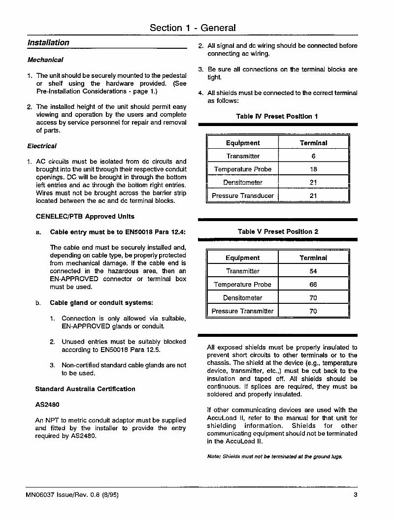


Section 1 - General
Figure 2 InterFace Board
J1J2
J4 J5
J3, J
6, J
7 an
d J8
MN06037 Issue/Rev. 0.8 (8/95) 7


Section 1 - General
Figure 4 AccuLoad II NEMA IV Dimensions
Note: Dimensions - Inches to the nearesttenth (millimeteres to the nearestwhole mm), each independentlydimensioned from respectiveengineering drawings.
MN06037 Issue/Rev. 0.8 (8/95) 9


Section I - General
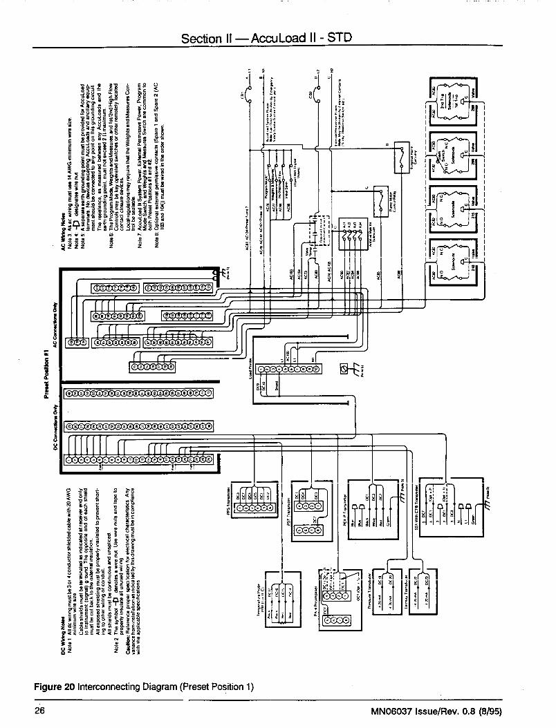
Figure 6 Terminal Block Layout - Graphics Panel
Not
es:
1.If
secu
rity
switc
hes
are
not u
sed,
thes
e te
rmin
als
shou
ld b
e tie
d to
the
inco
min
g po
wer
line
.2.
Jum
per P
ositi
ons
show
n fo
r 120
or 2
40 o
pera
tion.
3.P
rese
t Pos
ition
#1
- Red
- DC
con
nect
ions
1 th
roug
h 24
, 43,
and
44
- AC
con
nect
ions
73
and
74, 8
0 th
roug
h 10
54.
Pre
set P
ositi
on #
2- Y
ello
w- D
C c
onne
ctio
ns 4
5 an
d 46
, 49
thro
ugh
72- A
C c
onne
ctio
ns 7
5 an
d 76
, 106
thro
ugh
131
5.C
omm
on to
bot
h P
rese
t Pos
ition
s- W
hite
- DC
con
nect
ions
25
thro
ugh
42- A
C c
onne
ctio
ns 7
7 th
roug
h 79
, 132
thro
ugh
134
MN06037 Issue/Rev. 0.8 (8/95) 11


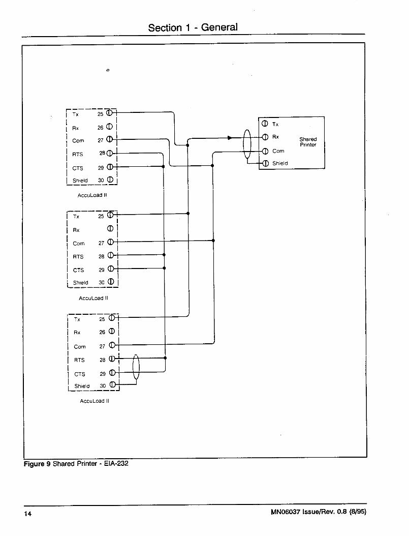
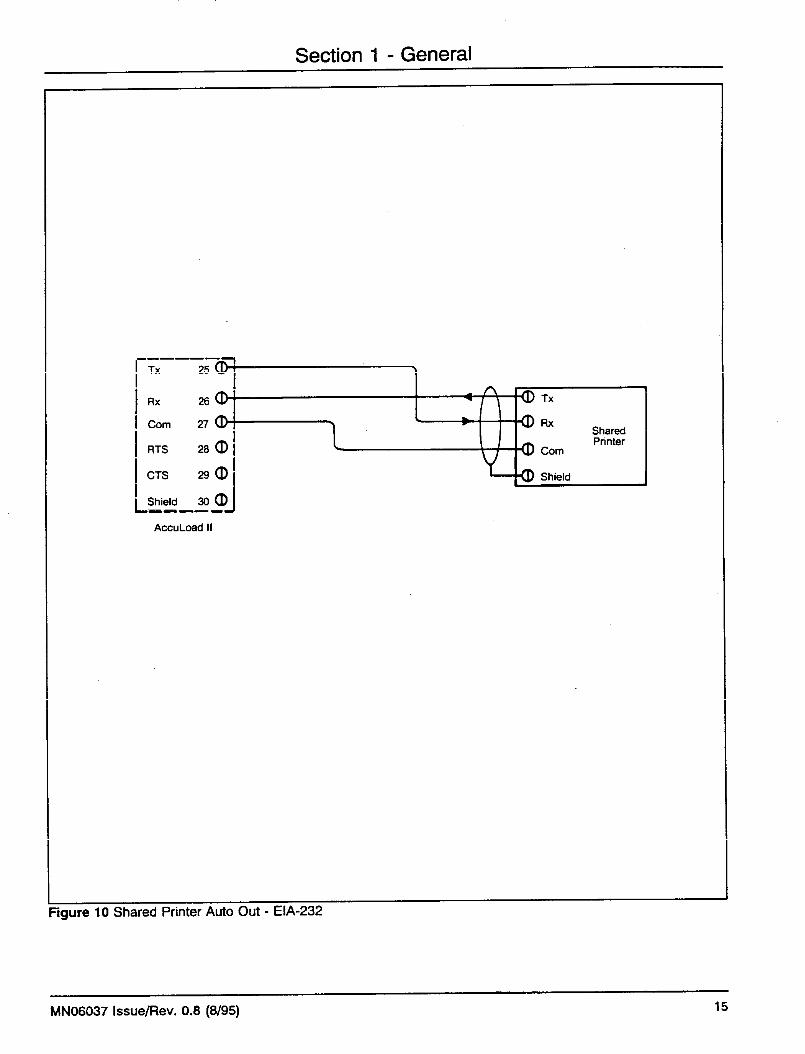


Figure 16 Quad OPV
Section 1 - General
1. After assembling QOPV kit to AccuLoad II, connect numbered wires from header(part of QOPV Board) to corresponding terminal points on AccuLoad II I/O Board.
MN06037 Issue/Rev. 0.8 (8/95) 21
Printer OutputJumpers

Figure 17 Remote Start
Section 1 - General
1. Locate jumper locations J1 and J2 on the keypad board.2. Mount shunt plugs as indicated above for both J1 and J2. (J1 - Preset Position #1 and J2 -
Preset Position #2).3. Wire remote start input to ac terminal 103 (Preset Position #1) and ac terminal 110
(Preset Position #2).4. Program both Preset Positions for Remote Stop under Permissive Sense #1 in the 800
directory of the program.
for RemoteStart on Position #2
for RemoteStart on Position #1
MN06037 Issue/Rev. 0.8 (8/95)22

Figure 18 Remote Stop
Section 1 - General
1. Locate jumper locations J8 and J9 on the computer board.2. Mount shunt plugs as indicated above in lower two positions of both J8 and J9.
(J8 - Preset Position #2 and J9 - Preset Position #1)3. Wire remote stop input to ac terminal 104 ( Preset Position #1) and ac terminal 111
(Preset Position #2).4. Program both Preset Positions for Remote Stop under Permissive Sense #2 in the 800
directory of the program.
MN06037 Issue/Rev. 0.8 (8/95) 23


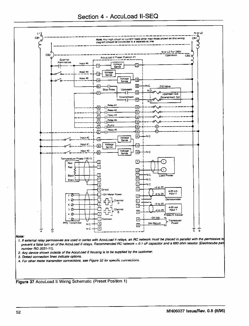

Section 4 - AccuLoad II-SEQ
Note:1. If external relay permissives are used in series with AccuLoad II relays, an RC network must be placed in parallel with the
permissive to prevent a false turn on of the AccuLoad II relays. Recommended RC network = 0.1 uF capacitor and a 680 ohm resistor (Electrocube part number RG 2031-11).
2. Any device shown outside of the AccuLoad II housing is to be supplied by the customer.
3. Dotted connection lines indicate options.
4. For other meter transmitter connections, see Figure 33 for specific connections.
75
110
76VoltageSense
VoltageSense
VoltageSense
112
ExternalPermissives
Input #6
AccuLoad II Preset Position #2
111
Input #4
Input #5
114
115
Stop Relay
124
128
130
119
121
126
Relay #1
Relay #2
Relay #3
Relay #4
Pump
Relay #5
118
Upstream
Downstream
125
127
129
131
120
122
123
N.C.
N.O.116
N.C.117
210 ValveUpstream Sol.
Downstream Sol.
AIJ-1 Sol.
AIJ-2 Sol.
AIJ-3 Sol.
AIJ-4 Sol.
N.C.
R1
R2
108Input #3
106Input #1
107Input #2
VoltageSense
VoltageSense
VoltageSense
109
113 N.C.
62
63
64
65
66
54
55
49
50
52
53
51
56
67
Temperature Probe (100 Ω)
Red
Red
Black
Black
1
4
3
6
5
2
PPS Transmitter N.C.
N.C.
Shield
-12V Meter Power
Channel A
Channel B
Common
57
71
61
60
59
58
Load PrinterN.C.
N.C.
N.C.
72
+4 to 20
-4 to 204-20 mAInput 2
68
69
+4 to 20
-4 to 204-20 mAInput 1
70 Densitometer
Pressure Xducer
45
46
TransducerPower
+24 Vdc
24V Return
A B
A BD C
1
2
Figure 38 AccuLoad II Wiring Schematic (Preset Position 2)
MN06037 Issue/Rev. 0.8 (8/95) 53


Section 5 - Related Publications
The following literature can be obtained from FMC Technologies Measurements Solutions, Inc. Literature Fulfillmentat [email protected] or online at www.fmctechnologies.com/measurementsolutions. When requesting literature fromLiterature Fulfillment, please reference the appropriate brochure number and title.
ValvesModel 210 - Specifications ................................................................................................................ Bulletin SS03009Model 210 - Installation/Operation......................................................................................................Bulletin MN03010Model 215 - Specifications ................................................................................................................ Bulletin SS03010Model 215 - Installation/Operation......................................................................................................Bulletin MN03006Model 215 - Service ..........................................................................................................................Bulletin MN03007Parts List ................................................................................................................................ Consult Parts Operation
Printed in U.S.A. © 8/95 FMC Technologies Measurement Solutions, Inc. All rights reserved. MN06037 Issue/Rev. 0.8 (8/95)
Visit our website at www.fmctechnologies.com
The specifications contained herein are subject to change without notice and any user of said specifications should verify from the manufacturer that thespecifications are currently in effect. Otherwise, the manufacturer assumes no responsibility for the use of specifications which may have been changed and areno longer in effect.
Headquarters:1803 Gears Road, Houston, TX 77067 USA, Phone: 281/260-2190, Fax: 281/260-2191
Gas Measurement Products:Erie, PA USA Phone 814/898-5000Thetford, England Phone (44) 1842-82-2900Kongsberg, Norway Phone (47) 32/286-700Buenos Aires, Argentina Phone 54 (11) 4312-4736
Integrated Measurement Systems:Corpus Christi, TX USA Phone 361/289-3400Kongsberg, Norway Phone (47) 32/286-700San Juan, Puerto Rico Phone 787/274-3760United Arab Emirates, Dubai Phone 971 +4/331-3646
Liquid Measurement Products:Erie, PA USA Phone 814/898-5000Los Angeles, CA USA Phone 661/702-8660Slough, England Phone (44) 1753-57-1515Ellerbek, Germany Phone (49) 4101-3040Barcelona, Spain Phone (34) 93/201-0989Moscow, Russia Phone (7) 495/564-8705Melbourne, Australia Phone (61) 3/9807-2818
Beijing, China Phone (86) 10/6500-2251Singapore Phone (65) 6861-3011Chennai, India Phone (91) 44/450-4400