accumulators - elektrotehnika.mk · quality accumulators and related parts through continuous...
TRANSCRIPT
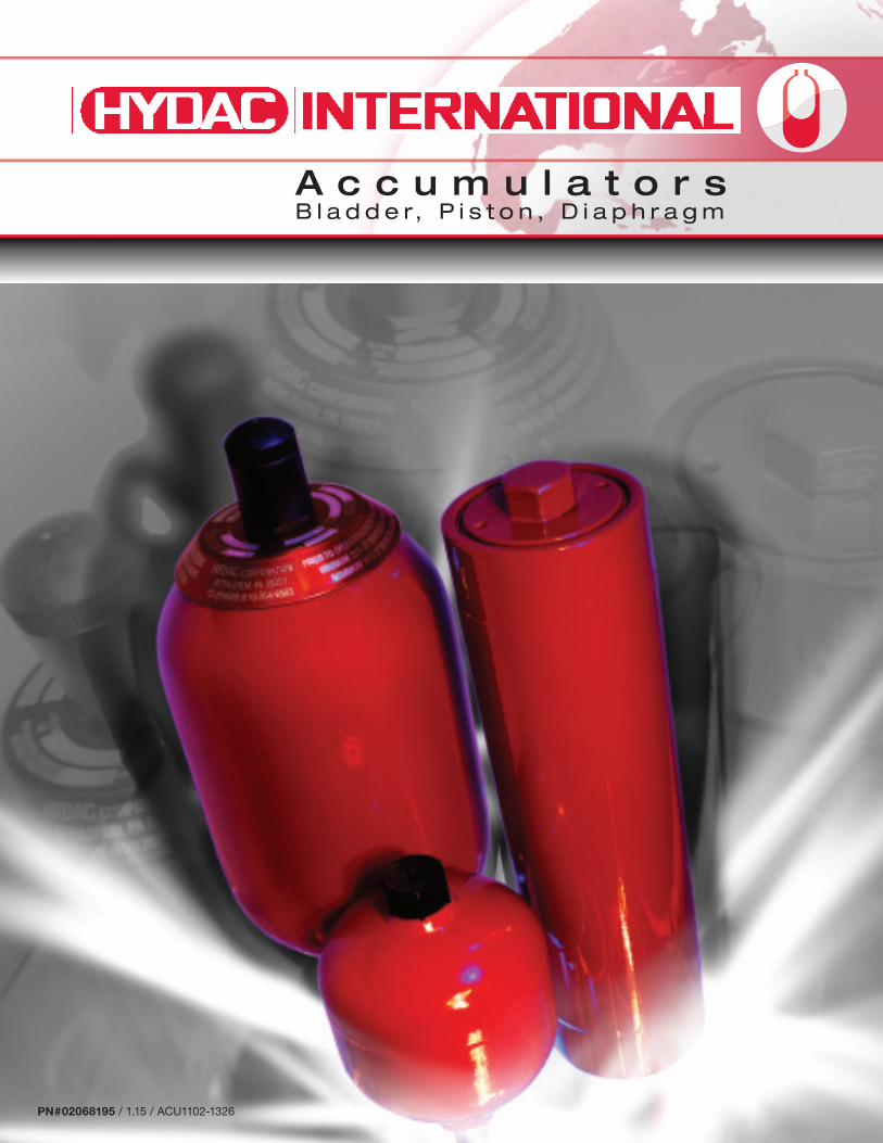
A c c u m u l a t o r sB l a d d e r, P i s t o n , D i a p h r a g m
PN#02068195 / 1.15 / ACU1102-1326

About HYDACHYDAC stands for worldwide presence and accessibility to the customer. HYDAC has over 1000 distributors worldwide and more than 50 wholly owned branches. HYDAC accumulators – a name synonymous with advanced technology, design, manufacturing and application engineering for more than 50 years, is considered a global leader throughout the hydraulic industry.
HYDAC is the only worldwide manufacturer producing bladder, piston, and diaphragm accumulators and hydraulic dampeners. Not only does HYDAC supply the most comprehensive hydraulic accumulator range, but also the best technical solution to every application. HYDAC accumulators are supplied with the appropriate pressure vessel certifications to the laws governing the country of installation.
HYDAC stands for quality and customer service. HYDAC achieves the highest quality accumulators and related parts through continuous research and development in our laboratories for testing of physical, chemical, and mechanical properties. To ensure that HYDAC accumulators and related products are as innovative as possible with optimum performance and safety, a Finite Element Analysis is implemented during the Computer Aided Design process.
Our internal staff and worldwide distribution network take care of the important matter of customer service. HYDAC values high standards, professional ethics, and mutual respect in all transactions with customers, vendors, and employees. We invest in our relationships by providing expertise, quality, dependability, and accessibility to foster growth and a sense of partnership. Our customer service representatives are committed to serving the customers’ needs.
Energy and Environmental TechnologyHYDAC accumulators have played a key role in providing innovative solutions resulting in lowering operational costs and increasing hydraulic system performance in hydroelectric, wind, and waste power plants. HYDAC has vast expertise in applying accumulator technology within the power generation industry.
Mobile MarketThe aim of our engineers has always been to reduce volume and weight, resulting in increased product performance. HYDAC provides compact high performance accumulators for the Mobile Market. HYDAC accumulators can be found on all types of construction, forestry, and agricultural equipment.
Process TechnologyHYDAC accumulators can be found in paper mills, steel mills, manufacturing plants, foundries, power plants, and in the chemical, petrochemical and plastics industries worldwide. For more than 50 years HYDAC has been supplying accumulators to companies who require the most advanced process technology.
Offshore Shipbuilding and Marine TechnologyMaritime technology places special demands on material functionality and reliability. HYDAC accumulators meet these demands due to our high quality and test standards. HYDAC accumulators have been applied under the toughest conditions from drilling rigs to deep sea applications.
Industrial EngineeringOur knowledge and expertise in a diverse set of industries translates into a comprehensive range of versatile hydraulic accumulators. HYDAC offers many solutions for machine tools, plastic injection molding machines, test equipment, presses, and metal forming machines. Other industrial applications include: steel and heavy industry, power transmission and paper mills.
HYDAC Customer Service
HYDAC Quality
HYDAC Products
PN#02068195 / 1.15/ ACU1102-1326

Table of Contents
INNOVATIVE FLUID POWER
IntroductionGeneral Introduction . . . . . . . . . . . . . . . . . . . . . 2Certification . . . . . . . . . . . . . . . . . . . . . . . . . . . . 3Overview . . . . . . . . . . . . . . . . . . . . . . . . . . . . . . . 4Industries & Applications . . . . . . . . . . . . . . . . . . 8
Safety EquipmentSafety Equipment Overview . . . . . . . . . . . . . . . . 9Protection on the Fluid Side . . . . . . . . . . . . . . . . 9Protection on the Gas Side . . . . . . . . . . . . . . . 10
Bladder AccumulatorsSB Series . . . . . . . . . . . . . . . . . . . . . . . . . . . . . 11Water Service . . . . . . . . . . . . . . . . . . . . . . . . . . 15Stainless Steel . . . . . . . . . . . . . . . . . . . . . . . . . 16Oil & Gas / Offshore . . . . . . . . . . . . . . . . . . . . . 17 Spare Parts . . . . . . . . . . . . . . . . . . . . . . . . . . . . 20
Diaphragm AccumulatorsSBO Series . . . . . . . . . . . . . . . . . . . . . . . . . . . . 23Water Service . . . . . . . . . . . . . . . . . . . . . . . . . . 27
Piston AccumulatorsSK Series Overview . . . . . . . . . . . . . . . . . . . . . 28Model Code . . . . . . . . . . . . . . . . . . . . . . . . . . . 31Connections . . . . . . . . . . . . . . . . . . . . . . . . . . . 32 Dimensions . . . . . . . . . . . . . . . . . . . . . . . . . . . . 36Spare Parts . . . . . . . . . . . . . . . . . . . . . . . . . . . . 40
Nitrogen BottlesSN Series . . . . . . . . . . . . . . . . . . . . . . . . . . . . . 41
Pulsation DampenersSB...P & SBO...P . . . . . . . . . . . . . . . . . . . . . . . . 44
Metal BellowsSM50 & SM50P . . . . . . . . . . . . . . . . . . . . . . . . 48
AccessoriesThermal Fuse Caps . . . . . . . . . . . . . . . . . . . . . 51Thermal Fuse Plug . . . . . . . . . . . . . . . . . . . . . . 52SAF Series Safety & Shut-off Blocks . . . . . . . . . . . . . . . . . 53 Safety & Shut-off Blocks Spare Parts. . . . . . . 59FPK & FPS Series Charging & Gauging Units . . . . . . . . . . . . . . . . 60 FPO Series . . . . . . . . . . . . . . . . . . . . . . . . . . . . 62Charging & Gauging Adapters . . . . . . . . . . . . . 63Charging & Gauging Spare Parts . . . . . . . . . . . 66Permanent Gauging Block . . . . . . . . . . . . . . . . 68Mounting Components . . . . . . . . . . . . . . . . . . 70
Application ExamplesTypical Applications . . . . . . . . . . . . . . . . . . . . . 75Shock Absorbers . . . . . . . . . . . . . . . . . . . . . . . 77
Sizing AccumulatorsOperational Sequence Steps . . . . . . . . . . . . . . 78Behavior & Formulas . . . . . . . . . . . . . . . . . . . . 79Pulsation Dampeners . . . . . . . . . . . . . . . . . . . . 81Bladder, Diaphragm & Piston Form . . . . . . . . . 82Shock Applications Form . . . . . . . . . . . . . . . . . 83Pulsation Dampening Form . . . . . . . . . . . . . . . 84
Information and related materials are subject to change without notice. This catalog, and all information and related materials it contains, are provided “as is.” HYDAC makes no representation or warranty what-soever regarding the completeness, accuracy, “up-to-dateness”, or adequacy of, the HYDAC-NA domain and this catalog.
INNOVATIVE FLUID POWER2 PN#02068195 / 1.15 / ACU1102-1326
FunctionsAs an essential element in modern hydraulics, accumulators perform many useful functions, such as:
• reducing pump capacity and electrical energy
• providing auxiliary hydraulic power in case of an emergency
• limiting pressure fluctuations during temperature changes in a closed hydraulic loop
• compensation for leakage
• minimizing pump pulsations
• absorbing shocks
Benefits• increasing system performance and efficiency
• lowering operating and maintenance costs
• providing fail-safe conditions
• avoiding pump, pipe and system failures to achieve longer life expectancy
Accessories All accessories required for installation and maintenance of accumulators are available, including:
• safety and shut off blocks
• mounting components
• accumulator sets
• charging and gauging units
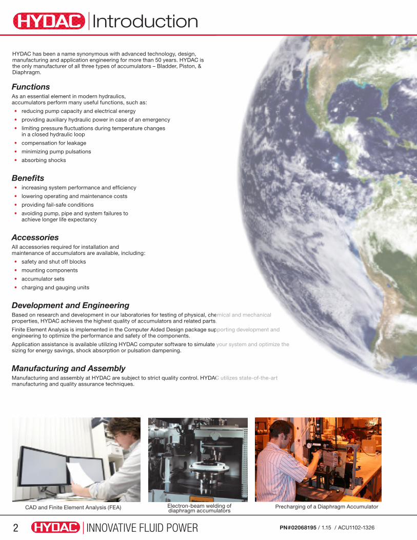
Development and EngineeringBased on research and development in our laboratories for testing of physical, chemical and mechanical properties, HYDAC achieves the highest quality of accumulators and related parts.
Finite Element Analysis is implemented in the Computer Aided Design package supporting development and engineering to optimize the performance and safety of the components.
Application assistance is available utilizing HYDAC computer software to simulate your system and optimize the sizing for energy savings, shock absorption or pulsation dampening.
Manufacturing and AssemblyManufacturing and assembly at HYDAC are subject to strict quality control. HYDAC utilizes state-of-the-art manufacturing and quality assurance techniques.
Introduction
CAD and Finite Element Analysis (FEA) Electron-beam welding of diaphragm accumulators
Precharging of a Diaphragm Accumulator
HYDAC has been a name synonymous with advanced technology, design, manufacturing and application engineering for more than 50 years. HYDAC is the only manufacturer of all three types of accumulators – Bladder, Piston, & Diaphragm.
INNOVATIVE FLUID POWER 3PN#02068195 / 1.15 / ACU1102-1326
Algeria S3)
Argentina S3)
Australia F1)
Austria UBahamas EBarbados S3)
Belgium UBermuda S3)
Bolivia S3)
Brazil S3)
Canada S12)
Chile S3)
China A9Costa Rica E3)
Czech Republic UDenmark UEcuador S3)
Egypt UFinland UFrance UGermany UGreece U
Hong Kong A9Hungary U3)
Iceland U3)
India S3)
Indonesia S3)
Iran UIraq S3)
Ireland UIsrael U3)
Italy UJapan PJordan S3)
Korea S3)
Kuwait S3)
Lebanon S3)
Libya S3)
Luxembourg UMalaysia S3)
Mexico S3)
New Zealand TNetherlands UNigeria S3)
Norway U3)
Pakistan S3)
Peru S3)
Philippines S3)
Poland UPortugal UPuerto Rico S3)
Romania URussia (CIS) A6Saudi Arabia S3)
Singapore USlovakia A8South Africa S3)
Spain USudan S3)
Sweden USwitzerland USyria UTaiwan S3)
Thailand S3)
Tunisia S3)
Turkey UUnited Kingdom UUSA SVenezuela S3)
European Union Member States (listed in bold below) On November 29, 1999 the directive 97/23/EC (Pressure Equipment Directive) came into force and has been operative since May 29, 2002. This directive applies to the design, manufacture, conformity assessment and circulation of pressure equipment and assemblies with a maximum permissible pressure of over 0.5 bar. It guarantees the free movement of goods within the European Community. EU member states must not prohibit, restrict or obstruct the circulation and commissioning of pressure equipment on account of pressure-related hazards, if the equipment complies with the requirements of the pressure equipment directive, has the CE mark, and is subject to a conformity assessment.
China (Self quality for China) HYDAC Technology GmbH is recognized as an importer of bladder, diaphragm and piston accumulators since March 30, 1998.
Japan (KHK certificate) For the Japanese market, HYDAC Technology GmbH is approved as a “self inspecting manufacturer”. Therefore HYDAC is authorized to manufacture, test and import accumulators from outside Japan.
For details on other country certifications, please contact HYDAC.
Complete Country Code Listing(European Union Member States listed in bold below)
Certification
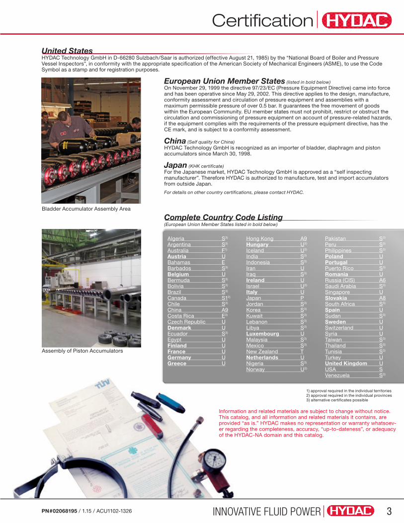
Bladder Accumulator Assembly Area
Assembly of Piston Accumulators
1) approval required in the individual territories2) approval required in the individual provinces3) alternative certificates possible
United States HYDAC Technology GmbH in D-66280 Sulzbach/Saar is authorized (effective August 21, 1985) by the “National Board of Boiler and Pressure Vessel Inspectors”, in conformity with the appropriate specification of the American Society of Mechanical Engineers (ASME), to use the Code Symbol as a stamp and for registration purposes.
Information and related materials are subject to change without notice. This catalog, and all information and related materials it contains, are provided “as is.” HYDAC makes no representation or warranty whatsoev-er regarding the completeness, accuracy, “up-to-dateness”, or adequacy of the HYDAC-NA domain and this catalog.

INNOVATIVE FLUID POWER4 PN#02068195 / 1.15 / ACU1102-1326
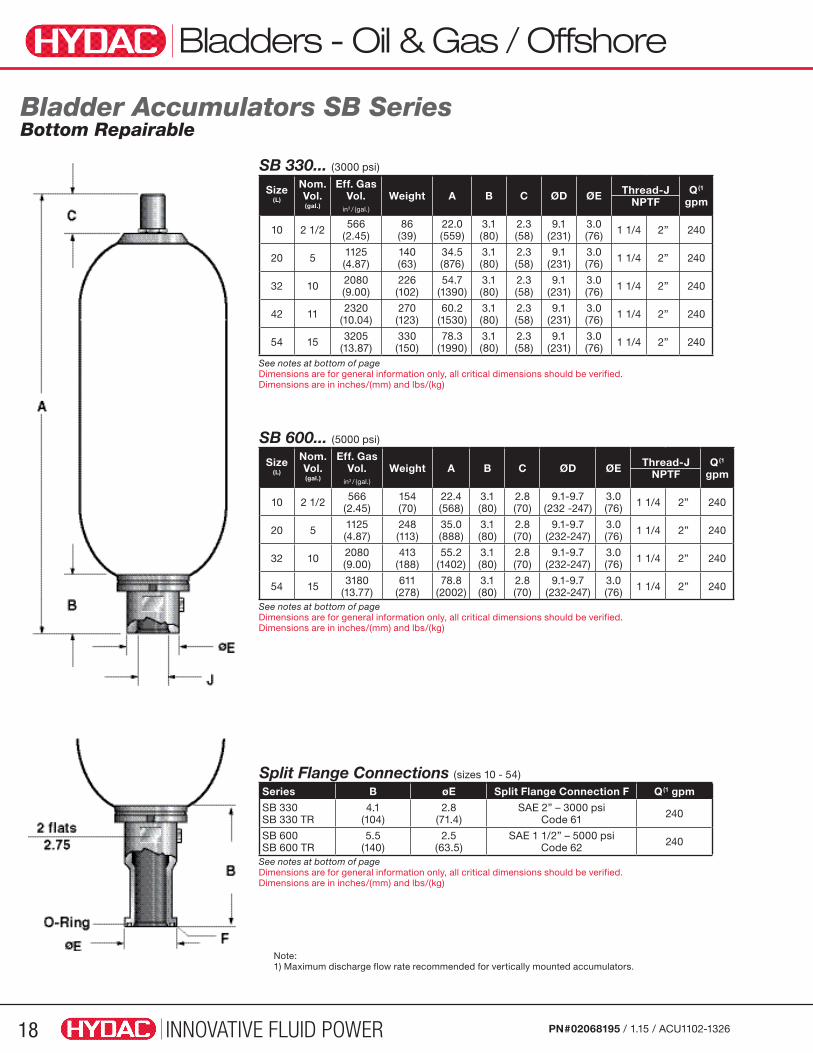
Bladder AccumulatorsThe standard bladder accumulator consists of a “closed” rubber bladder inside a forged steel shell. A mechanically actuated valve closes when the fluid has been expelled, blocking off the fluid port, thereby enclosing the bladder within the shell. Where high discharge rates are required, a high flow model is available.
Applications with corrosive environments may require shells furnished with an internal and/or external coating or manufactured from stainless steel.
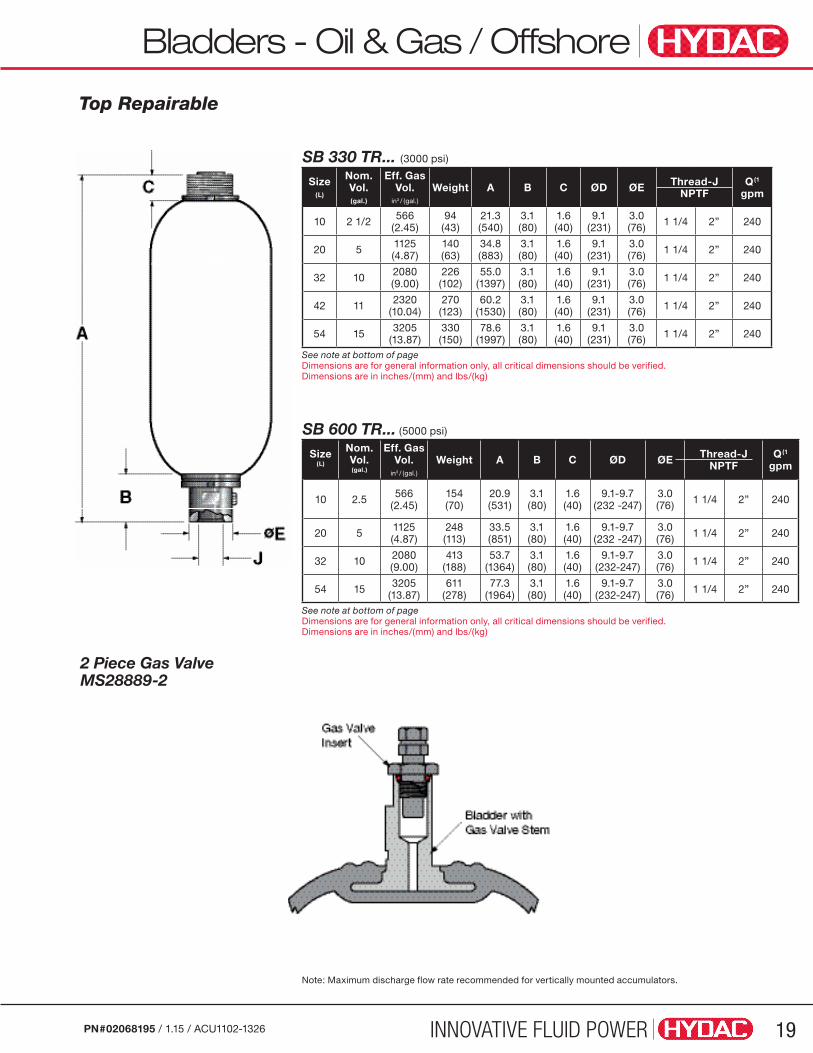
The top repairable accumulator permits service and maintenance of the bladder without removing the accumulator from the hydraulic system.
When the pressure level of a system permits, a low pressure accumulator may be used. It is similar to a standard bladder accumulator, except that the poppet valve is replaced by a perforated plate covering the fluid port, and the shell may be of welded construction.
For lightweight applications, a Kevlar wrapped accumulator shell is available. The wrapping supports the thinner metal shell to provide a substantial weight reduction.
Diaphragm AccumulatorsA diaphragm accumulator performs the same function as a bladder accumulator, however, it operates like a membrane. A poppet is molded into the bottom of the diaphragm to prevent its extrusion through the fluid port.
Diaphragm accumulators are frequently used where small volumes are required, weight is important, a higher pressure ratio is required (up to 10:1) or low cost is a prime factor.
Applications with corrosive environments may require a coating or be manufactured from stainless steel.
Overview
Low Pressure High FlowHigh Pressure
Piston AccumulatorsA piston accumulator consists of a fluid section and a gas section with the piston acting as a gas-proof screen. The gas section is precharged with dry nitrogen gas. Auxiliary gas bottles are frequently used with piston accumulators to provide the required gas volume.
Threaded (repairable)
Electric Proximity Switches
Bottom Repairable Kevlar WrappedTop Repairable
Standard Extending Piston Rod
Welded (non-repairable)
Sealed Factory Precharge
OEM - (non-repairable)

INNOVATIVE FLUID POWER 5PN#02068195 / 1.15 / ACU1102-1326
Overview
Type Design Nominal Volume
MAWP (psi)
Pressure Ratio
Flow Rate
Mounting Position Weight Cost
Diaphragm • small volume and flow
• low weight
• compact design • good for shock
applications (good response characteristics)
5 in3 to 1 gal
3000, 5000 (up to
10,000)
8:1 typically
(up to 10:1)
up to 60 gpm
any lowest lowest
Bladder• best general purpose
• wide range of standard sizes
• good for shock applications (good response characteristics)
1 qt. to
15 gal
3000, 5000 (up to
10,000)4:1
up to 480 gpm
prefer vertical
middle middle
Piston • best for large stored volumes
• best for high flow rates • not recommended for
shock applications
• best for use with backup nitrogen bottles
1 qt. to
100 gal
3000, 5000 (up to
10,000)∞:1
up to 2000 gpm
prefer vertical
highestmiddle to highest
Comparison of Standard Accumulators
Stainless Steel AccumulatorsStainless steel piston and diaphragm accumulators are available in various sizes and pressure ranges. They offer special corrosion resistance that is required for chemical and off-shore industries, petro-chemical and nuclear power plants and for food applications.
Piston Diaphragm
Accumulator Type Selection Considerations• System Pressure
• System Temperature
• Volume / Usable Volume
• Flow Rate
• Pressure Ratio
• Installation Space and Position
• Chemical Compatibility
Use the comparison chart above as a quick reference guide.
Bladder
INNOVATIVE FLUID POWER6 PN#02068195 / 1.15 / ACU1102-1326
Overview
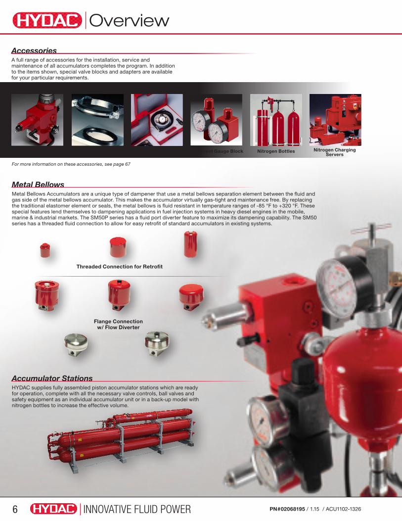
Metal BellowsMetal Bellows Accumulators are a unique type of dampener that use a metal bellows separation element between the fluid and gas side of the metal bellows accumulator. This makes the accumulator virtually gas-tight and maintenance free. By replacing the traditional elastomer element or seals, the metal bellows is fluid resistant in temperature ranges of -85 °F to +320 °F. These special features lend themselves to dampening applications in fuel injection systems in heavy diesel engines in the mobile, marine & industrial markets. The SM50P series has a fluid port diverter feature to maximize its dampening capability. The SM50 series has a threaded fluid connection to allow for easy retrofit of standard accumulators in existing systems.
Accumulator Stations HYDAC supplies fully assembled piston accumulator stations which are ready for operation, complete with all the necessary valve controls, ball valves and safety equipment as an individual accumulator unit or in a back-up model with nitrogen bottles to increase the effective volume.
AccessoriesA full range of accessories for the installation, service and maintenance of all accumulators completes the program. In addition to the items shown, special valve blocks and adapters are available for your particular requirements.
For more information on these accessories, see page 67
Safety & Shut-off Blocks Permanent Gauge Block Nitrogen Charging Servers
Charging UnitsMounting Nitrogen Bottles
Threaded Connection for Retrofit
Flange Connection w/ Flow Diverter

INNOVATIVE FLUID POWER 7PN#02068195 / 1.15 / ACU1102-1326
Overview
DampenersPulsations and shocks in hydraulic lines can result in costly damage to the piping and other system components. Reciprocating piston pumps by design create pressure pulsations, vibrations, and noise in the system. HYDAC suction stabilizers, pulsation dampeners and silencers, when applied to piston pumps, will reduce pulsations and noise. Furthermore, pressure pulsations can make control in servo systems nearly impossible without installing a pulsation dampener. HYDAC shock absorbers can be applied to greatly reduce shock wave energy. These waves can be harmful to all components in your hydraulic system. Shock waves can be created by closing a valve in a high flow line, such as one found in a petroleum terminal.
PTFE Dampeners - Aggressive MediaHYDAC has developed an all-PTFE cup diaphragm and has patented its design and application. It is resistant to aggressive operating fluids and can be installed in almost all standard diaphragm accumulators which are available in both carbon steel and stainless steel.
Diaphragm Dampener Standard & High Pressure Bladder Dampener
Pulsation Dampener PVDF w/ PTFE diaphragm
Silencers Suction Flow Stabilizer

INNOVATIVE FLUID POWER8 PN#02068195 / 1.15 / ACU1102-1326
Applications
Industries and ApplicationsIndustrial Hydraulics
Machine tools• Support for the hydraulics for tool drive or tool change
• Energy storage in the compact hydraulics of machining centers
Plastics technology• Accumulator stations for energy storage during the injection molding process
• Pulsation damping on the hydraulic drive
Die casting machines• Energy storage for injection process
• Volume compensation using diaphragm accumulators
Steel industry• Energy storage in rolling mills
• Blast furnace hydraulics
Power plants• Emergency supply for turbine control system
• Pulsation damping on pumps
• Lubrication, control and seal oil supply
• Water treatment
Paper industry• Energy storage for emergency functions in friction bearing hydraulics
• Energy storage in high/low pressure power units
Wind energy• Accumulators in the pitch control system
• Support of the pitch drive
• Accumulator on braking units
Mobile Technology
Agricultural and forestry machines• Front loader damping
• Accumulators in tractor suspension systems
• Stone strike protection for ploughs
• Boom suspension on field sprayers
Construction machinery• Accumulator in braking systems
• Chassis damping
• Bucket damping
Cranes and commercial vehicles• Accumulators for boom damping on mobile cranes
• Accumulators in steering systems of HGVs
• Accumulators in hydraulic switching systems
Rail vehicles• Temperature and leakage oil adjustment
• Chassis controls
• Level control
• Pump noise damping
Automotive• Automatic and manual transmission
• Automatic clutch systems
• Engine management systems
• Pump noise damping
Process Technology
Chemical industry• Energy storage and pulsation damping on dosing pumps
• Suction flow stabilization on the suction side of pumps
Oil & Gas / Offshore• Accumulators to support valve closing systems
• Energy storage for deep sea rams
• Blow Out Preventers (BOP)\Emergency function for safety systems
• Accumulators on wellhead control systems
Loading station / Refineries• Shock absorption for valve closing
• Pulsation damping on pipelines

INNOVATIVE FLUID POWER 9PN#02068195 / 1.15 / ACU1102-1326
Safety Requirements
FAILURE OR IMPROPER SELECTION OR IMPROPER USE OF THE PRODUCTS AND/OR SYSTEMS DESCRIBED HEREIN OR RELATED ITEMS CAN CAUSE DEATH, PERSONAL INJURY
AND PROPERTY DAMAGE.This document and other information from HYDAC, its subsidiaries and authorized distributors provide product and/or system options for further investigation by users having technical expertise. It is important that you analyze all aspects of your application and review the information concerning the product or system in the current product catalog. Due to the variety of operating conditions and applications for these products or systems, the user, through its own analysis and testing, is solely responsible for making the final selection of the products and systems and assuring that all performance, safety and warning requirements of the application are met.
HYDAC does not assume the risk of and shall not be liable for failure due to fire. HYDAC offers fire safety devices and recommends their use.
The products described herein, including without limitation, product features, specifications, designs, availability and pricing, are subject to change by HYDAC Corporation and its subsidiaries at any time without notice.
WARNING!
CAUTION!
The fluid side has to be protected against excessive pressures with approved safety valves. HYDAC provides the pressure relief valve (DB12 Series) which has a pressure setting (set by HYDAC) up to 5800 psi (400 bar). The sealed valves carry a CE mark, and are integrated into the Safety and Shut-off Blocks in nominal sizes DN10 to DN32.
(See pages 53-59 for more details)
All accumulators should be visually inspected (signs of leakage etc.), tested for functionality and have a complete seal change out within 10 years of service.
Safety Requirements OverviewHydro-pneumatic accumulators are pressure equipments subjected to legal pressure regulations. For the operation and the testing of accumulator equipped hydraulics, all local regulations have to be observed to avoid any risks and to guarantee the safety for the whole lifetime of the units.
Therefore “safety devices in accordance with the PED 97/23/EC ANNEX 1:2.11” are available.
HYDAC offers various types of standard “safety devices”, which should be used on the gas and fluid sides to protect against pressures in excess of design parameters.
Protection on the Fluid SideSafety Devices
Note: The information in this brochure relates to the operating conditions and applications described. For applications or operating conditions not described, please contact Product Management at HYDAC.
Information and related materials are subject to change without notice. This catalog, and all information and related materials it contains, are provided “as is.” HYDAC makes no representation or warranty whatsoever regarding the completeness, accuracy, “up-to-dateness”, or adequacy of the HYDAC-NA domain and this catalog.

Safety Equipment
INNOVATIVE FLUID POWER10 PN#02068195 / 1.15 / ACU1102-1326
Protection on the Gas SideExcess pressure on the gas side, especially by increased ambient temperatures (e.g. in case of a fire) has to be reduced completely or controlled with safety devices.
To achieve this, HYDAC offers three different types of protection which are available as optional equipment:
Gas Safety Valves
Note: The information in this brochure relates to the operating conditions and applications described.
For applications or operating conditions not described, please contact Product Management at HYDAC.
Protection by means of controlled pressure reduction when pressure exceeds the permitted level.
The Gas Safety Valve (GSV6 Series) is a direct-operating, spring loaded safety valve with a setting range of 435 to 5366 psi (30 to 370 bar) within a temperature range of -4° to 176°F (-20° to 80°C).
All the components of the valve are in stainless steel and therefore suitable for a variety of applications. The GSV6 Series will be supplied with a Declaration of Conformity and an operating instruction manual. Due to its self-centering seal ring, fitting is simple and safe.
Model Code Pressure Setting ±5% Part Number
GSV6-10-CE1637.ISO4126-1.6.G.015.030 450 psi (30 bar) 3123965
GSV6-10-CE1637.ISO4126-1.6.G.095.160 2320 psi (160 bar) 3124038
GSV6-10-CE1637.ISO4126-1.6.G.125.210 3045 psi (210 bar) 3124043
GSV6-10-CE1637.ISO4126-1.6.G.148.250 3626 psi (250 bar) 3124047
GSV6-10-CE1637.ISO4126-1.6.G.205.350 5076 psi (350 bar) 3124057Note: Others available on request
Protection by means of complete discharge in the case of excessive temperature and pressure.
Thermal Fuse Cap and Plugs are “safety devices” and are used for permissible working pressures of up to 690 bar in a temperature range of -40° to 176°F. Their melting point is approximately 320° to 356°F and bleeds off the gas pressure by discharging the nitrogen completely when the rise in temperature reaches unacceptable levels (e.g. in case of fire).
Model Code Part Number
Thermal Fuse Caps 7/8-14UNF 363501
GMP6-10-CE1637.6.G.120L/S.350Bar ISO228-G 1/4 3517438
GMP6-10-CE1637.6.G.120L/S.350Bar ISO228-G 1/2 3517439
Thermal Fuse Caps and Plugs
Burst Discs Protection by means of complete discharge when pressure exceeds the permitted level.
Burst discs are designed for different pressure settings and will be supplied with a Declaration of Conformity.
If their set pressure is exceeded, the burst disc is destroyed. The passage remains open and discharges the nitrogen completely.
Burst discs are made entirely of stainless steel and/or stainless steel / nickel alloy.
Model Code Burst Pressure ±10% at 122°F Part Number
Burst Disc Plug 1/4 NPT 3045 psi (210 bar) 3156148
Burst Disc Plug 1/4 NPT 3626 psi (250 bar) 3156150
Burst Disc Plug 1/4 NPT 5076 psi (350 bar) 3156152
Burst Disc Plug 1/4 NPT 6527 psi (450 bar) 3156155Note: higher pressures on request
WARNING: HYDAC does not assume the risk of and shall not be liable for failure due to fire. HYDAC offers fire safety devices and recommends their use.
Bladder Accumulators
INNOVATIVE FLUID POWER 11PN#02068195 / 1.15 / ACU1102-1326
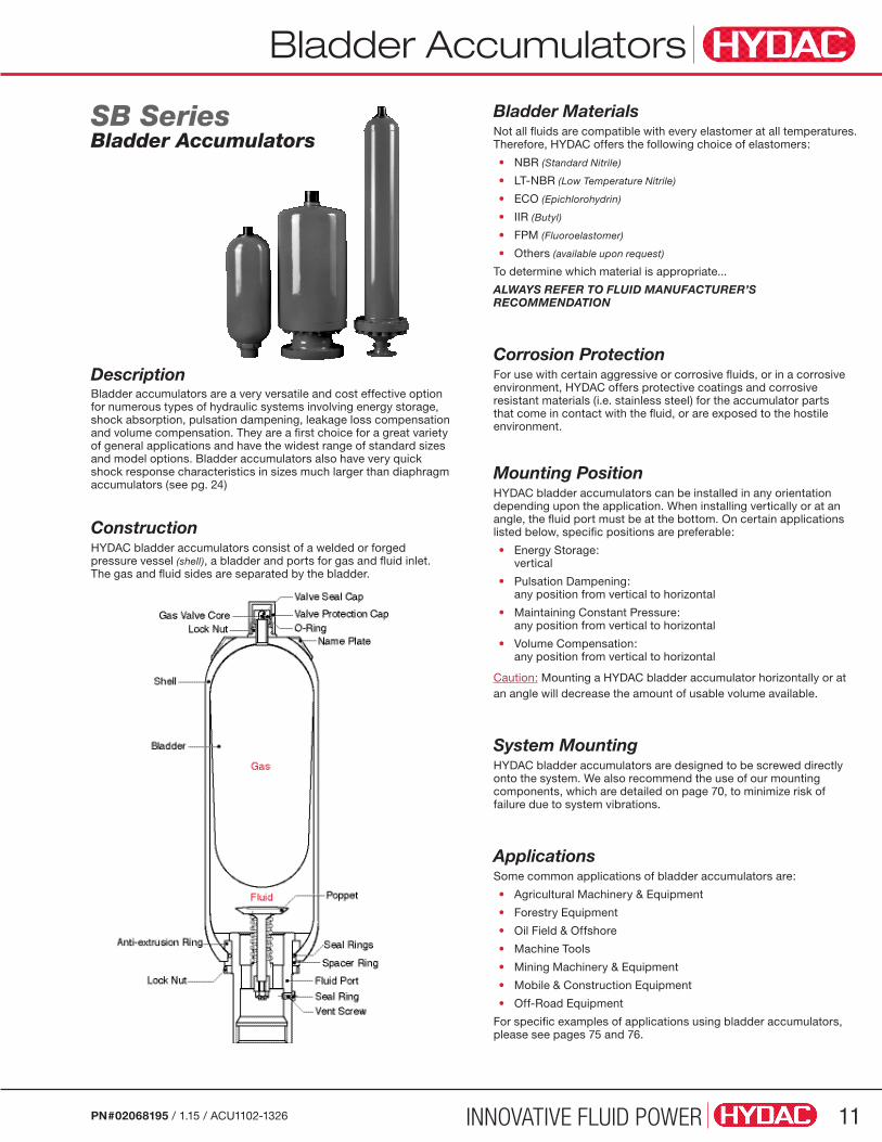
SB SeriesBladder Accumulators
Bladder MaterialsNot all fluids are compatible with every elastomer at all temperatures. Therefore, HYDAC offers the following choice of elastomers:
• NBR (Standard Nitrile)
• LT-NBR (Low Temperature Nitrile)
• ECO (Epichlorohydrin)
• IIR (Butyl)
• FPM (Fluoroelastomer)
• Others (available upon request)
To determine which material is appropriate...
ALWAYS REFER TO FLUID MANUFACTURER’S RECOMMENDATION
Corrosion ProtectionFor use with certain aggressive or corrosive fluids, or in a corrosive environment, HYDAC offers protective coatings and corrosive resistant materials (i.e. stainless steel) for the accumulator parts that come in contact with the fluid, or are exposed to the hostile environment.
Mounting PositionHYDAC bladder accumulators can be installed in any orientation depending upon the application. When installing vertically or at an angle, the fluid port must be at the bottom. On certain applications listed below, specific positions are preferable:
• Energy Storage: vertical
• Pulsation Dampening: any position from vertical to horizontal
• Maintaining Constant Pressure: any position from vertical to horizontal
• Volume Compensation: any position from vertical to horizontal
Caution: Mounting a HYDAC bladder accumulator horizontally or at an angle will decrease the amount of usable volume available.
System MountingHYDAC bladder accumulators are designed to be screwed directly onto the system. We also recommend the use of our mounting components, which are detailed on page 70, to minimize risk of failure due to system vibrations.
ApplicationsSome common applications of bladder accumulators are:
• Agricultural Machinery & Equipment
• Forestry Equipment
• Oil Field & Offshore
• Machine Tools
• Mining Machinery & Equipment
• Mobile & Construction Equipment
• Off-Road Equipment
For specific examples of applications using bladder accumulators, please see pages 75 and 76.
Description Bladder accumulators are a very versatile and cost effective option for numerous types of hydraulic systems involving energy storage, shock absorption, pulsation dampening, leakage loss compensation and volume compensation. They are a first choice for a great variety of general applications and have the widest range of standard sizes and model options. Bladder accumulators also have very quick shock response characteristics in sizes much larger than diaphragm accumulators (see pg. 24)
ConstructionHYDAC bladder accumulators consist of a welded or forged pressure vessel (shell), a bladder and ports for gas and fluid inlet. The gas and fluid sides are separated by the bladder.

Bladder Accumulators
INNOVATIVE FLUID POWER12 PN#02068195 / 1.15 / ACU1102-1326
Model CodeModel Codes containing RED selections are non-standard items – Contact HYDAC for information and availability Not all combinations are available
SB 330 - 20 A 1 / 112 S – 210 C XXXSeries SB 330 = Bladder accumulator (3000 psi, Typically) SB 600 = Bladder accumulator (5000 psi, Typically)Design (omit) = Standard (bottom repairable) N = Modified Flow (396 gpm) H = High Flow (480 gpm) TR = Standard (top repairable) NTR = Modified Flow (396 gpm) (top repairable)
Size (in Liters, see dimension tables on following pages for most common sizes) 1 = 1 quart 4 = 1 gallon 6 = 1.5 gallons 10 = 2.5 gallons 20 = 5 gallons 32 = 10 gallons 42 = 11 gallons 54 = 15 gallonsLine Connection A = Threaded F = FlangedGas Port 1 = Standard model, HYDAC gas valve version 4 (8V1 - ISO 4570)Material CodeDepending on Application 112 = Standard for oil service (mineral oil)
Fluid Port 0 = Synthetic coated carbon steel (PTFE solid film, internal & external for water service) 1 = Carbon steel 2 = High strength stainless steel (typically 17-4 PH) 3 = Stainless steel (corrosion resistance, (typically 316 ss) 4 = Chemically plated carbon steel (internal & external for water service) 6 = Low temperature carbon steel (<-40°F, min)Shell 0 = Synthetic coated carbon steel (PTFE solid film, internal & external for water service) 1 = Carbon steel 2 = Chemically plated carbon steel (internal & external for water service) 6 = Low temperature carbon steel (<-40°F, min) 7 = Others available on requestBladder Compound 2 = NBR (Buna N) 3 = ECO (Hydrin) 4 = IIR (Butyl) 5 = LT-NBR (low temp. Buna) 6 = FPM (Fluoroelastomer) 7 = Others (available on request)
Country of Installation S = USA S1 = Canada (CRN registered) W1 = ABS Type Approval W3 = DNV Type Approval U = PED/CE (for other countries see page 3 for proper code designation)
Maximum Working Pressure in bar 210 = 3000 psi 345 = 5000 psiFluid Port Connection A = BSPP (ISO 228) Radial Seal Design NOT Axial B = Metric (DIN 13) Threaded C = SAE (ANSI B1.1) D = NPT (ANSI B1.2) E = SAE 2” - 3000 psi (Code 61) Flanged F = SAE 1 1/2” - 6000 psi (Code 62) G = SAE 1 1/4” - 3000 psi (Code 61) (only available in sizes 4 liters & 6 liters) H = SAE 1” - 6000 psi (Code 62) (only available in sizes 1 liter & 4 liters)
Gas Precharge Pressure (Po) in bar xxx = 3 digits
Compound Oper. Temp Range Typical FluidsNBR 5˚ to 180˚F mineral oils
32˚ to 180˚F water & water-glycols (5% minimum glycol)LT-NBR -50˚ to 180˚F mineral oilsECO...113... -20˚ to 250˚F mineral oilsECO...663... -40˚ to 250˚F mineral oils (with low temperature CS shell)IIR -20˚ to 200˚F phosphate esters & brake fluidsFPM 5˚ to 300˚F chlorinated hydrocarbons
Bladder Accumulators
INNOVATIVE FLUID POWER 13PN#02068195 / 1.15 / ACU1102-1326
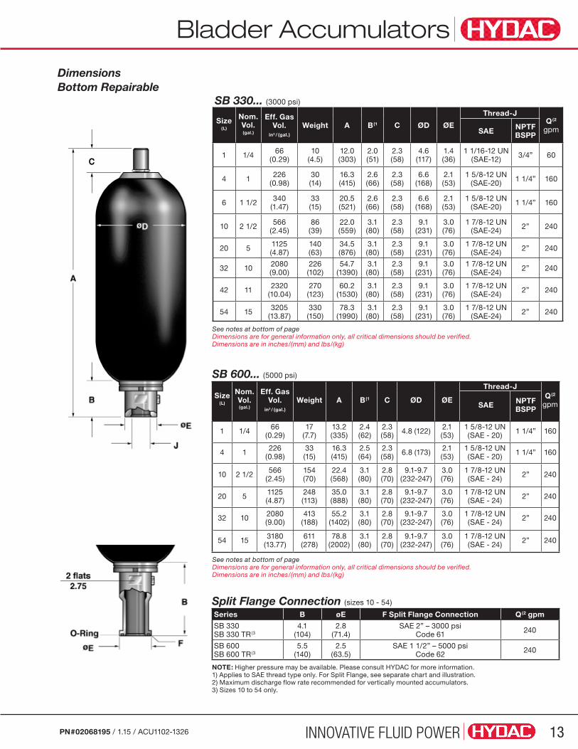
NOTE: Higher pressure may be available. Please consult HYDAC for more information.1) Applies to SAE thread type only. For Split Flange, see separate chart and illustration.2) Maximum discharge flow rate recommended for vertically mounted accumulators.3) Sizes 10 to 54 only.
SB 600... (5000 psi)
Size(L)
Nom. Vol. (gal.)
Eff. Gas Vol.
in3 / (gal.)
Weight A B(1 C ØD ØE
Thread-JQ(2
gpm SAE NPTFBSPP
1 1/4 66(0.29)
17 (7.7)
13.2 (335)
2.4 (62)
2.3 (58) 4.8 (122) 2.1
(53)1 5/8-12 UN(SAE - 20) 1 1/4” 160
4 1 226(0.98)
33 (15)
16.3 (415)
2.5 (64)
2.3 (58) 6.8 (173) 2.1
(53)1 5/8-12 UN (SAE - 20) 1 1/4” 160
10 2 1/2 566(2.45)
154 (70)
22.4 (568)
3.1 (80)
2.8 (70)
9.1-9.7 (232-247)
3.0 (76)
1 7/8-12 UN (SAE - 24) 2” 240
20 5 1125(4.87)
248 (113)
35.0 (888)
3.1 (80)
2.8 (70)
9.1-9.7 (232-247)
3.0 (76)
1 7/8-12 UN (SAE - 24) 2” 240
32 10 2080(9.00)
413 (188)
55.2 (1402)
3.1 (80)
2.8 (70)
9.1-9.7 (232-247)
3.0 (76)
1 7/8-12 UN (SAE - 24) 2” 240
54 15 3180(13.77)
611 (278)
78.8 (2002)
3.1 (80)
2.8 (70)
9.1-9.7 (232-247)
3.0 (76)
1 7/8-12 UN (SAE - 24) 2” 240
SB 330... (3000 psi)
Size(L)
Nom. Vol. (gal.)
Eff. Gas Vol.
in3 / (gal.)
Weight A B(1 C ØD ØE
Thread-JQ(2
gpmSAE NPTFBSPP
1 1/4 66(0.29)
10 (4.5)
12.0 (303)
2.0 (51)
2.3 (58)
4.6 (117)
1.4 (36)
1 1/16-12 UN(SAE-12) 3/4” 60
4 1 226(0.98)
30 (14)
16.3 (415)
2.6 (66)
2.3 (58)
6.6 (168)
2.1 (53)
1 5/8-12 UN(SAE-20) 1 1/4” 160
6 1 1/2 340(1.47)
33 (15)
20.5 (521)
2.6 (66)
2.3 (58)
6.6 (168)
2.1 (53)
1 5/8-12 UN(SAE-20) 1 1/4” 160
10 2 1/2 566(2.45)
86 (39)
22.0 (559)
3.1 (80)
2.3 (58)
9.1 (231)
3.0 (76)
1 7/8-12 UN(SAE-24) 2” 240
20 5 1125(4.87)
140 (63)
34.5 (876)
3.1 (80)
2.3 (58)
9.1 (231)
3.0 (76)
1 7/8-12 UN (SAE-24) 2” 240
32 10 2080(9.00)
226 (102)
54.7 (1390)
3.1 (80)
2.3 (58)
9.1 (231)
3.0 (76)
1 7/8-12 UN (SAE-24) 2” 240
42 11 2320(10.04)
270 (123)
60.2 (1530)
3.1 (80)
2.3 (58)
9.1 (231)
3.0 (76)
1 7/8-12 UN (SAE-24) 2” 240
54 15 3205(13.87)
330 (150)
78.3 (1990)
3.1 (80)
2.3 (58)
9.1 (231)
3.0 (76)
1 7/8-12 UN (SAE-24) 2” 240
Dimensions Bottom Repairable
Split Flange Connection (sizes 10 - 54)
Series B øE F Split Flange Connection Q(2 gpm
SB 330 SB 330 TR(3
4.1 (104)
2.8 (71.4)
SAE 2” – 3000 psi Code 61 240
SB 600 SB 600 TR(3
5.5 (140)
2.5 (63.5)
SAE 1 1/2” – 5000 psi Code 62 240
See notes at bottom of pageDimensions are for general information only, all critical dimensions should be verified.Dimensions are in inches/(mm) and lbs/(kg)
See notes at bottom of pageDimensions are for general information only, all critical dimensions should be verified.Dimensions are in inches/(mm) and lbs/(kg)
Bladder Accumulators
INNOVATIVE FLUID POWER14 PN#02068195 / 1.15 / ACU1102-1326
Dimensions are for general information only, all critical dimensions should be verified.Dimensions are in inches/(mm) and lbs/(kg)
Note: 1) Applies to SAE thread type only. For Split Flange, see chart and illustration on previous page.2) Maximum discharge flow rate recommended for vertically mounted accumulators.
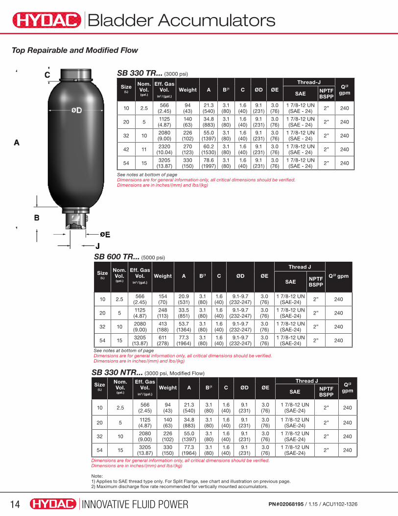
SB 600 TR... (5000 psi)
Size(L)
Nom. Vol. (gal.)
Eff. Gas Vol.
in3 / (gal.)
Weight A B(1 C ØD ØE
Thread J
Q(2 gpmSAE NPTF
BSPP
10 2.5 566(2.45)
154(70)
20.9(531)
3.1(80)
1.6(40)
9.1-9.7 (232-247)
3.0 (76)
1 7/8-12 UN(SAE-24) 2” 240
20 5 1125(4.87)
248 (113)
33.5 (851)
3.1 (80)
1.6 (40)
9.1-9.7 (232-247)
3.0 (76)
1 7/8-12 UN(SAE-24) 2” 240
32 10 2080(9.00)
413 (188)
53.7 (1364)
3.1 (80)
1.6 (40)
9.1-9.7 (232-247)
3.0 (76)
1 7/8-12 UN (SAE-24) 2” 240
54 15 3205(13.87)
611(278)
77.3 (1964)
3.1 (80)
1.6 (40)
9.1-9.7 (232-247)
3.0 (76)
1 7/8-12 UN (SAE-24) 2” 240
SB 330 TR... (3000 psi)
Size(L)
Nom. Vol. (gal.)
Eff. Gas Vol.
in3 / (gal.)
Weight A B(1 C ØD ØEThread-J
Q(2
gpmSAE NPTFBSPP
10 2.5 566(2.45)
94 (43)
21.3 (540)
3.1 (80)
1.6 (40)
9.1 (231)
3.0 (76)
1 7/8-12 UN(SAE - 24) 2” 240
20 5 1125(4.87)
140 (63)
34.8 (883)
3.1 (80)
1.6 (40)
9.1 (231)
3.0 (76)
1 7/8-12 UN (SAE - 24) 2” 240
32 10 2080(9.00)
226 (102)
55.0 (1397)
3.1 (80)
1.6 (40)
9.1 (231)
3.0 (76)
1 7/8-12 UN (SAE - 24) 2” 240
42 11 2320(10.04)
270 (123)
60.2 (1530)
3.1 (80)
1.6 (40)
9.1 (231)
3.0 (76)
1 7/8-12 UN (SAE - 24) 2” 240
54 15 3205(13.87)
330 (150)
78.6 (1997)
3.1 (80)
1.6 (40)
9.1 (231)
3.0 (76)
1 7/8-12 UN (SAE - 24) 2” 240
SB 330 NTR... (3000 psi, Modified Flow)
Size(L)
Nom. Vol. (gal.)
Eff. Gas Vol.
in3 / (gal.)
Weight A B(1 C ØD ØEThread J
Q(2 gpmSAE NPTF
BSPP
10 2.5 566(2.45)
94 (43)
21.3(540)
3.1(80)
1.6(40)
9.1 (231)
3.0 (76)
1 7/8-12 UN(SAE-24) 2” 240
20 5 1125(4.87)
140 (63)
34.8(883)
3.1 (80)
1.6 (40)
9.1 (231)
3.0 (76)
1 7/8-12 UN(SAE-24) 2” 240
32 10 2080(9.00)
226 (102)
55.0(1397)
3.1 (80)
1.6 (40)
9.1 (231)
3.0 (76)
1 7/8-12 UN (SAE-24) 2” 240
54 15 3205(13.87)
330 (150)
77.3(1964)
3.1 (80)
1.6 (40)
9.1 (231)
3.0 (76)
1 7/8-12 UN (SAE-24) 2” 240
See notes at bottom of pageDimensions are for general information only, all critical dimensions should be verified.Dimensions are in inches/(mm) and lbs/(kg)
See notes at bottom of pageDimensions are for general information only, all critical dimensions should be verified.Dimensions are in inches/(mm) and lbs/(kg)
Top Repairable and Modified Flow

INNOVATIVE FLUID POWER 15PN#02068195 / 1.15 / ACU1102-1326
Bladder Accumulators
Water ServiceRED selections are non-standard items – Contact HYDAC for information and availability Not all combinations are available
Size (L)
Effective Gas Vol (in3)
MAWP psi/(bar) Model Code P/N Fluid Connection Thread Size
1 66 3000 (210) SB330-1A1/002S-210C 2055285 SAE 1 1/16" - 12 UN
4 226 3000 (210) SB330-4A1/002S-210C 2055070 SAE 1 5/8" - 12 UN
4 226 3000 (210) SB330-4A1/005S-210C 2092089 SAE 1 5/8" - 12 UN
4 226 3000 (210) SB330-4A1/006S-210D (USES 1.25" NPT ADAP) 2091080 1 1/4" NPT
6 340 3000 (210) SB330-6A1/002S-210D (USES 1.25" NPT ADAP) 2092310 1 1/4" NPT
10 566 3000 (210) SB330-10A1/002S-210C 2055224 SAE 1 7/8" - 12 UN
10 566 3000 (210) SB330-10A1/002S-210D 2087571 2" NPT
10 566 3000 (210) SB330-10F1/002S-210E 2069474 Flanged SAE 2" (Code 61)
20 1125 3000 (210) SB330-20A1/002S-210C 2054720 SAE 1 7/8" - 12 UN
20 1125 3000 (210) SB330-20A1/002S-210D 2087570 2" NPT
20 1125 3000 (210) SB330-20A1/002S1-210A CRN 2082666 2" BSPP
20 1125 3000 (210) SB330-20A1/002S1-210C CRN 2084359 SAE 1 7/8" - 12 UN
20 1125 3000 (210) SB330-20F1/002S-210E 2072909 Flanged SAE 2" (Code 61)
32 2080 3000 (210) SB330-32A1/002S-210C 2083387 SAE 1 7/8" - 12 UN
32 2080 3000 (210) SB330-32A1/002S-210D 2063921 2" NPT
32 2080 3000 (210) SB330-32F1/002S-210E 2072536 Flanged SAE 2" (Code 61)
54 3205 3000 (210) SB330-54A1/002S-210C 2055269 SAE 1 7/8" - 12 UN
54 3205 3000 (210) SB330-54A1/002S-210D 2069311 2" NPT
54 3205 3000 (210) SB330-54A1/002S1-210A CRN 2082667 2" BSPP
54 3205 3000 (210) SB330-54F1/002S-210E 2055105 Flanged SAE 2" (Code 61)
1 66 5000 (345) SB600-1A1/002S-345C 2054911 SAE 1 5/8" - 12 UN
1 66 5000 (345) SB600-1F1/002S-345H 2094814 Flanged SAE 1" (Code 62)
4 226 5000 (345) SB600-4A1/002S-345C 2055063 SAE 1 5/8" - 12 UN
10 566 5000 (345) SB600-10A1/002S-345C 2055093 SAE 1 7/8" - 12 UN
10 566 5000 (345) SB600-10A1/002S1-345C CRN 2093123 SAE 1 7/8" - 12 UN
10 566 5000 (345) SB600-10F1/002S-345F 2089028 Flanged SAE 1 1/2" (Code 62)
20 1125 5000 (345) SB600-20A1/002S-345C 2056383 SAE 1 7/8" - 12 UN
20 1125 5000 (345) SB600-20F1/002S-345F 2083359 Flanged SAE 1 1/2" (Code 62)
32 2080 6000 (414) SB600-32A1/002S-414A 2070756 2" BSPP
32 2080 5000 (345) SB600-32F1/002S-345F 2076097 Flanged SAE 1 1/2" (Code 62)
54 3180 5000 (345) SB600-54A1/002S-345C 2062971 SAE 1 7/8" - 12 UN
54 3180 5000 (345) SB600-54A1/006S-345C 2094879 SAE 1 7/8" - 12 UN
54 3180 5000 (345) SB600-54F1/002S-345F 2074828 Flanged SAE 1 1/2" (Code 62)
INNOVATIVE FLUID POWER16 PN#02068195 / 1.15 / ACU1102-1326
Stainless Steel Bladders
Additional sizes available. For sizes above 15 gal., contact HYDAC Accumulator Product Management.
Model CodeModel Codes containing RED selections are non-standard items – Contact HYDAC for information and availability Not all combinations are available
SB 90 - 20 S 11/ 332S1-82C Series SB 50 = Bladder Accumulator (725 psi, Nominal) SB 90 = Bladder accumulator (1190 psi, Nominal)Size 10 = 2.5 gal 20 = 5 gal 35 = 10 gal 50 = 15 galLine Connection S = Threaded (SAE Lock Nut) F = Flanged (SAE Lock Nut)Gas Port 11 = 2pc 316 SS Gas Valve (MS28889-2) (see page 68 for permanent gauge blocks. See page 60 for charging and gauging info, FPO is recommended)Fluid port 3 = 316 Stainless steelShell 3 = 316 Stainless steel (Static Storage Temp -40 Deg C to 100 Deg C) Vessel OnlyBladder Compound 2 = NBR (Buna N) 3 = ECO (Hydrin) 4 = IIR (Butyl) 5 = LT-NBR (low temp. Buna) 6 = FPM (Fluoroelastomer) 7 = Others (available on request)
Country of Installation S1 = USA & CanadaMaximum Working Pressure (in bar) 50 = SB50’s 725 PSI 82 = SB90’s 1189 PSIFluid Port Connection (316SS) Threaded C = SAE D = NPT Flanged E = SAE 2” - 3000 psi
SB 90... (1190 psi)
Nom. Vol.
(L)
Eff. Gas Vol.
in3 / (gal.)
Weight A B(1 C ØD ØE
Thread J
SAE NPTF
10 566 59(31)
21.2(538)
3.1 (80)
2.3(58)
8.6(219)
3.0 (76)
1 7/8-12 UN(SAE-24) 2”
20 1125 102(46)
33.4(848)
3.1 (80)
2.3(58)
8.6(219)
3.0 (76)
1 7/8-12 UN (SAE-24) 2”
35 2080 146(66)
53.9(1368)
3.1 (80)
2.3(58)
8.6(219)
3.0 (76)
1 7/8-12 UN (SAE-24) 2”
50 3205 212(96)
77.9(1978)
3.1 (80)
2.3(58)
8.6(219)
3.0 (76)
1 7/8-12 UN(SAE-24) 2”
Dimensions are in inches/(mm) and lbs/(kg)
Compound Oper. Temp Range Typical FluidsNBR 5˚ to 180˚F mineral oils
32˚ to 180˚F water & water-glycols (5% minimum glycol)LT-NBR -50˚ to 180˚F mineral oilsECO...113... -20˚ to 250˚F mineral oilsECO...663... -40˚ to 250˚F mineral oils (with low temperature CS shell)IIR -20˚ to 200˚F phosphate esters & brake fluidsFPM 5˚ to 300˚F chlorinated hydrocarbons
Model Code Part Number
SB90-10S11/332S-82C 2200084
SB90-20S11/332S-82C 2200090
SB90-35S11/332S-82C 2200097
SB90-50S11/332S-82C 2200101

Bladders - Oil & Gas / Offshore
INNOVATIVE FLUID POWER 17PN#02068195 / 1.15 / ACU1102-1326
Model Code Model Codes containing RED selections are non-standard items – Contact HYDAC for information and availability Not all combinations are available
SB 330 - 20 S 11 / 112 S – 210 C XXXSeries SB 330 = Bladder accumulator (3000 psi, Typically) SB 600 = Bladder accumulator (5000 psi, Typically)
Design (omit) = Standard (bottom repairable) TR = Top Repairable
Size (see dimension tables on the previous pages for most common sizes) 10 = 2.5 gallons 20 = 5 gallons 32 = 10 gallons 42 = 11 gallons 54 = 15 gallons
Line Connection S = Threaded (SAE Lock Nut) F = Flanged (SAE Lock Nut)
Gas Port 11 = 2 Piece Gas Valve (see pg 19 for details)
Material Code Depending on Application 112 = Standard for oil service (mineral oil)
Fluid Port 0 = Synthetic coated carbon steel (PTFE solid film, internal & external for water service) 1 = Carbon steel 2 = High strength stainless steel (typically 17-4 PH) 3 = Stainless steel (corrosion resistance) (typically 316SS) 4 = Chemically plated carbon steel (internal & external for water service) 6 = Low temperature carbon steel (<-40°F, min) 7 = Others available on request
Shell 0 = Synthetic coated carbon steel (PTFE solid film, internal & external for water service) 1 = Carbon steel 2 = Chemically plated carbon steel (internal & external for water service) 6 = Low temperature carbon steel (<-40°F) 7 = Others available on request
Bladder Compound 2 = NBR (Buna N) 3 = ECO (Hydrin) 4 = IIR (Butyl) 5 = LT-NBR (low temp. Buna) 6 = FPM (Fluoroelastomer) 7 = Others (available on request)
Country of Installation S = USA W1 = ABS Type Approval W3 = DNV Type Approval S1 = Canada (CRN Registration) U = PED/CE (for other countries see page 3 for proper code designation)
Maximum Working Pressure 210 = 3000 psi 345 = 5000 psi 414 = 6000 psi
Fluid Port Connection C = SAE (ANSI B1.1) Threaded D = NPT (ANSI B1.2) E = SAE 2” - 3000 psi (Code 61) Flanged F = SAE 1 1/2” - 6000 psi (Code 62)
Gas Precharge Pressure (Po) in bar xxx = 3 digits
Note: For the full line of bladder accumulators please refer to page 4.
Compound Oper. Temp Range Typical FluidsNBR -10˚ to 220˚F mineral oils
-10˚ to 220˚F water & water-glycols (5% minimum glycol)LT-NBR -50˚ to 180˚F mineral oilsECO...113... -20˚ to 250˚F mineral oilsECO...663... -40˚ to 250˚F mineral oils (with low temperature CS shell)IIR -20˚ to 200˚F phosphate esters & brake fluidsFPM 5˚ to 300˚F chlorinated hydrocarbons
INNOVATIVE FLUID POWER18
Bladders - Oil & Gas / Offshore
PN#02068195 / 1.15 / ACU1102-1326
Bladder Accumulators SB SeriesBottom Repairable
SB 600... (5000 psi)
Size (L)
Nom. Vol. (gal.)
Eff. Gas Vol.
in3 / (gal.)
Weight A B C ØD ØE Thread-J NPTF
Q(1 gpm
10 2 1/2 566 (2.45)
154(70)
22.4(568)
3.1(80)
2.8(70)
9.1-9.7(232 -247)
3.0(76) 1 1/4 2” 240
20 5 1125 (4.87)
248(113)
35.0(888)
3.1(80)
2.8(70)
9.1-9.7(232-247)
3.0(76) 1 1/4 2” 240
32 10 2080 (9.00)
413(188)
55.2(1402)
3.1(80)
2.8(70)
9.1-9.7(232-247)
3.0(76) 1 1/4 2” 240
54 15 3180(13.77)
611(278)
78.8(2002)
3.1(80)
2.8(70)
9.1-9.7(232-247)
3.0(76) 1 1/4 2” 240
SB 330... (3000 psi)
Size (L)
Nom. Vol. (gal.)
Eff. Gas Vol.
in3 / (gal.)
Weight A B C ØD ØE Thread-J NPTF
Q(1 gpm
10 2 1/2 566 (2.45)
86(39)
22.0(559)
3.1(80)
2.3(58)
9.1(231)
3.0(76) 1 1/4 2” 240
20 5 1125 (4.87)
140(63)
34.5(876)
3.1(80)
2.3(58)
9.1(231)
3.0(76) 1 1/4 2” 240
32 10 2080(9.00)
226(102)
54.7(1390)
3.1(80)
2.3(58)
9.1(231)
3.0(76) 1 1/4 2” 240
42 11 2320(10.04)
270(123)
60.2(1530)
3.1(80)
2.3(58)
9.1(231)
3.0(76) 1 1/4 2” 240
54 15 3205 (13.87)
330(150)
78.3(1990)
3.1(80)
2.3(58)
9.1(231)
3.0(76) 1 1/4 2” 240
Split Flange Connections (sizes 10 - 54)
Series B øE Split Flange Connection F Q(1 gpm
SB 330SB 330 TR
4.1(104)
2.8(71.4)
SAE 2” – 3000 psiCode 61 240
SB 600SB 600 TR
5.5(140)
2.5(63.5)
SAE 1 1/2” – 5000 psiCode 62 240
Note:1) Maximum discharge flow rate recommended for vertically mounted accumulators.
See notes at bottom of page Dimensions are for general information only, all critical dimensions should be verified.Dimensions are in inches/(mm) and lbs/(kg)
See notes at bottom of page Dimensions are for general information only, all critical dimensions should be verified.Dimensions are in inches/(mm) and lbs/(kg)
See notes at bottom of page Dimensions are for general information only, all critical dimensions should be verified.Dimensions are in inches/(mm) and lbs/(kg)
Bladders - Oil & Gas / Offshore
INNOVATIVE FLUID POWER 19PN#02068195 / 1.15 / ACU1102-1326
Top Repairable
SB 330 TR... (3000 psi)
Size (L)
Nom. Vol. (gal.)
Eff. Gas Vol.
in3 / (gal.)
Weight A B C ØD ØE Thread-J NPTF
Q(1 gpm
10 2 1/2 566 (2.45)
94(43)
21.3(540)
3.1(80)
1.6(40)
9.1(231)
3.0(76) 1 1/4 2” 240
20 5 1125 (4.87)
140(63)
34.8(883)
3.1(80)
1.6(40)
9.1(231)
3.0(76) 1 1/4 2” 240
32 10 2080 (9.00)
226(102)
55.0(1397)
3.1(80)
1.6(40)
9.1(231)
3.0(76) 1 1/4 2” 240
42 11 2320 (10.04)
270(123)
60.2(1530)
3.1(80)
1.6(40)
9.1(231)
3.0(76) 1 1/4 2” 240
54 15 3205(13.87)
330(150)
78.6(1997)
3.1(80)
1.6(40)
9.1(231)
3.0(76) 1 1/4 2” 240
SB 600 TR... (5000 psi)
Size (L)
Nom. Vol. (gal.)
Eff. Gas Vol.
in3 / (gal.)
Weight A B C ØD ØE Thread-J NPTF
Q(1
gpm
10 2.5 566(2.45)
154(70)
20.9(531)
3.1(80)
1.6(40)
9.1-9.7(232 -247)
3.0 (76) 1 1/4 2” 240
20 5 1125 (4.87)
248(113)
33.5 (851)
3.1 (80)
1.6 (40)
9.1-9.7(232 -247)
3.0 (76) 1 1/4 2” 240
32 10 2080 (9.00)
413(188)
53.7 (1364)
3.1 (80)
1.6 (40)
9.1-9.7(232-247)
3.0 (76) 1 1/4 2” 240
54 15 3205 (13.87)
611(278)
77.3 (1964)
3.1 (80)
1.6 (40)
9.1-9.7(232-247)
3.0 (76) 1 1/4 2” 240
2 Piece Gas Valve MS28889-2
Note: Maximum discharge flow rate recommended for vertically mounted accumulators.
See note at bottom of pageDimensions are for general information only, all critical dimensions should be verified.Dimensions are in inches/(mm) and lbs/(kg)
See note at bottom of pageDimensions are for general information only, all critical dimensions should be verified.Dimensions are in inches/(mm) and lbs/(kg)
INNOVATIVE FLUID POWER20 PN#02068195 / 1.15 / ACU1102-1326
Bladder Accumulators
Bladder Accumulators - Spare Parts
Top Repairable SB330T, SB330HT, SB330TR, SB330NTR, SB 600T, SB600TR, SB600NTR
Bottom Repairable SB330, SB330H, SB330N SB600, SB600N
Repair Kits consist of items SB330T, SB330TR, SB330NTR SB600T, SB600TR, SB600NTR: 2, 3, 5, 7, 15, 16, 23 (where applicable), 28, 29, 30 SB330HT: 2, 3, 5, 7, 23 (where applicable), 28, 29, 30
Seal Kits consist of items 15, 16, 23 (where applicable), 28, 29, 30
Repair Kits consist of items 2, 3, 4 (SB 600 only), 5, 7, 15, 16, 23 (where applicable)
Seal Kits consist of items 15, 16, 23 (where applicable)
Parts LegendGas Side
1 Shell
2 Bladder
3 Gas Valve Core
4 Gas Side Lock Nut
5 Valve Seal Cap
6 Valve Protection Cap
7 O-ring
Parts LegendGas Side
8 Name Plate
22 Gas Port Adapter
24 Anti-extrusion Ring
28 Flat Ring
29 O-ring
30 Back-up Ring
31 Gas Port Lock Nut
Fluid Side
9 Fluid Port
14 Anti-extrusion Ring
15 Flat Ring
16 O-ring
17 Spacer Ring
18 Fluid Port Lock Nut
19 Vent Screw
20 Seal Ring
23 Back-up Ring
Detail Z
Detail XSB 330: size 1 to 54SB 600: size 1 to 4SB 330N: size 1 to 54
SB 600: size 10 to 54SB 600N: size 10 to 54
Detail Z
Detail XSB 330 T: size 10 to 54SB330TR: size 10 to 54
SB330NTR: size 10 to 54SB 330 HT: size 20 to 54SB 600 T: size 20 to 54SB600TR: size 10 to 54SB600NTR: size 10 to 54
Detail YSB 330 T: size 10 to 54SB 330 HT: size 20 to 54SB330TR: size 10 to 54SB330NTR: size 10 to 54SB 600 T: size 20 to 54SB600TR: size 10 to 54SB600NTR: size 10 to 54
INNOVATIVE FLUID POWER 21PN#02068195 / 1.15 / ACU1102-1326
Bladder Accumulators
Seal Kits For seal kits and repair kits other than Buna N, and for sizes not listed please consult factory.
Tools
Bottom Repairable - Buna N*
Size3000 PSI 5000 PSI
Fluid Port Seal Kit Bladder Repair Kit Fluid Port Seal Kit Bladder Repair Kit
1 (1 qt.) 2054031 2054034 2054032 2054455
4 (1 gal.) 2054032 2054035 2054032 2054035
6 (1.5gal.) 2054032 2054677 N/A N/A
10 (2.5 gal.) 2054033 2054036 2054283 2054279
20 (5 gal.) 2054033 2054037 2054283 2054280
32 (10 gal.) 2054033 2054038 2054283 2054281
42 (11 gal.) 2054033 2075963 N/A N/A
54 (15 gal.) 2054033 2054039 2054283 2054282
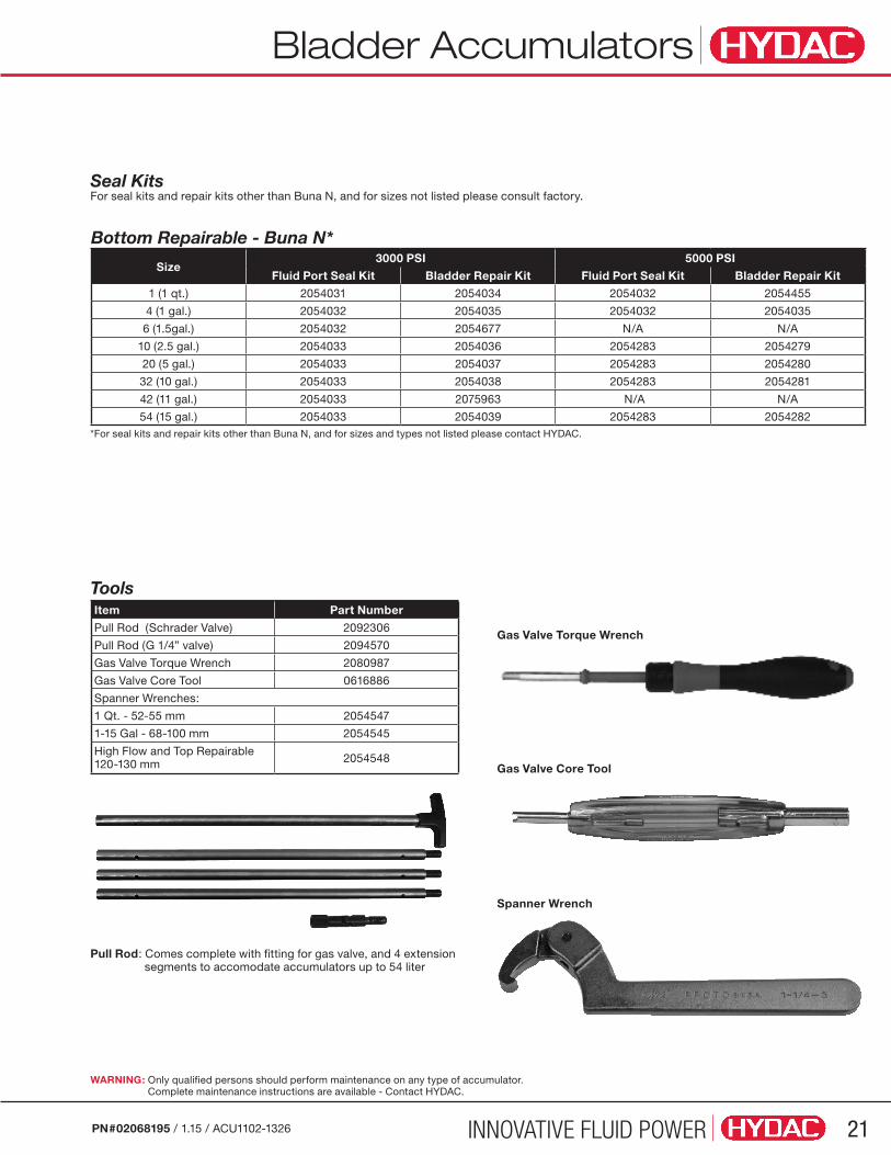
Item Part Number
Pull Rod (Schrader Valve) 2092306
Pull Rod (G 1/4” valve) 2094570
Gas Valve Torque Wrench 2080987
Gas Valve Core Tool 0616886
Spanner Wrenches:
1 Qt. - 52-55 mm 2054547
1-15 Gal - 68-100 mm 2054545
High Flow and Top Repairable 120-130 mm 2054548
Pull Rod: Comes complete with fitting for gas valve, and 4 extension segments to accomodate accumulators up to 54 liter
WARNING: Only qualified persons should perform maintenance on any type of accumulator. Complete maintenance instructions are available - Contact HYDAC.
Gas Valve Torque Wrench
Gas Valve Core Tool
Spanner Wrench
*For seal kits and repair kits other than Buna N, and for sizes and types not listed please contact HYDAC.
INNOVATIVE FLUID POWER22 PN#02068195 / 1.15 / ACU1102-1326
Bladder Accumulators
Footnotes 1 Only 14 gallon 2 Bladder only 3 Size of gas valve stem may be different than HYDAC standard (7/8”-14 UNF) 4 Style of gas valve stem (top-repairable) may differ
(i.e. has flat) from HYDAC 5 Not ASME approved; TUV approved accumulators only 6 Top-repairable only
7 Gas valve stem 7/8”-14 UNF 8 Gas valve stem 2” 9 Size and/or style of gas valve may be different than HYDAC standard 10 HYDAC Repair Kit consists of: • Bladder • Gas Valve Core • Lock Nut (SB 600 only) • Valve Seal Cap • Seal Kit
Competitive CrossoverBladder Accumulators
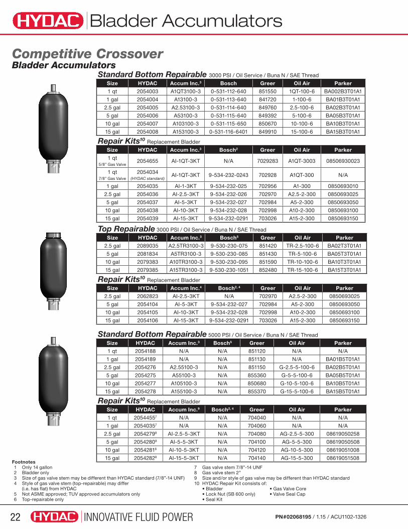
Standard Bottom Repairable 3000 PSI / Oil Service / Buna N / SAE Thread
Size HYDAC Accum Inc.3 Bosch Greer Oil Air Parker
1 qt 2054003 A1QT3100-3 0-531-112-640 851550 1QT-100-6 BA002B3T01A1
1 gal 2054004 A13100-3 0-531-113-640 841720 1-100-6 BA01B3T01A1
2.5 gal 2054005 A2.53100-3 0-531-114-640 849760 2.5-100-6 BA02B3T01A1
5 gal 2054006 A53100-3 0-531-115-640 849392 5-100-6 BA05B3T01A1
10 gal 2054007 A103100-3 0-531-115-650 850670 10-100-6 BA10B3T01A1
15 gal 2054008 A153100-3 0-531-116-6401 849910 15-100-6 BA15B3T01A1
Repair Kits10 Replacement Bladder
Size HYDAC Accum Inc.3 Bosch2 Greer Oil Air Parker
1 qt 5/8” Gas Valve
2054655 AI-1QT-3KT N/A 7029283 A1QT-3003 08506930023
1 qt 7/8” Gas Valve
2054034 (HYDAC standard)
AI-1QT-3KT 9-534-232-0243 702928 A1QT-300 N/A
1 gal 2054035 AI-1-3KT 9-534-232-025 702956 A1-300 0850693010
2.5 gal 2054036 AI-2.5-3KT 9-534-232-026 702970 A2.5-2-300 0850693025
5 gal 2054037 AI-5-3KT 9-534-232-027 702984 A5-2-300 0850693050
10 gal 2054038 AI-10-3KT 9-534-232-028 702998 A10-2-300 0850693100
15 gal 2054039 AI-15-3KT 9-534-232-0291 703026 A15-2-300 0850693150
Top Repairable 3000 PSI / Oil Service / Buna N / SAE Thread
Size HYDAC Accum Inc.3 Bosch5 Greer Oil Air Parker
2.5 gal 2089035 A2.5TR3100-3 9-530-230-075 851420 TR-2.5-100-6 BA02T3T01A1
5 gal 2081834 A5TR3100-3 9-530-230-085 851430 TR-5-100-6 BA05T3T01A1
10 gal 2079383 A10TR3100-3 9-530-230-095 851590 TR-10-100-6 BA10T3T01A1
15 gal 2079385 A15TR3100-3 9-530-230-1051 852480 TR-15-100-6 BA15T3T01A1
Repair Kits10 Replacement Bladder
Size HYDAC Accum Inc.4 Bosch2, 4 Greer Oil Air Parker
2.5 gal 2062823 AI-2.5-3KT N/A 702970 A2.5-2-300 0850693025
5 gal 2054104 AI-5-3KT 9-534-232-027 702984 A5-2-300 0850693050
10 gal 2054105 AI-10-3KT 9-534-232-028 702998 A10-2-300 0850693100
15 gal 2054106 AI-15-3KT 9-534-232-0291 703026 A15-2-300 0850693150
Standard Bottom Repairable 5000 PSI / Oil Service / Buna N / SAE Thread
Size HYDAC Accum Inc.3 Bosch5 Greer Oil Air Parker
1 qt 2054188 N/A N/A 851120 N/A N/A
1 gal 2054189 N/A N/A 851130 N/A BA01B5T01A1
2.5 gal 2054276 A2.55100-3 N/A 851150 G-2.5-5-100-6 BA02B5T01A1
5 gal 2054275 A55100-3 N/A 855360 G-5-5-100-6 BA05B5T01A1
10 gal 2054277 A105100-3 N/A 850680 G-10-5-100-6 BA10B5T01A1
15 gal 2054278 A155100-3 N/A 855370 G-15-5-100-6 BA15B5T01A1
Repair Kits10 Replacement Bladder
Size HYDAC Accum Inc.9 Bosch2, 4 Greer Oil Air Parker
1 qt 20544557 N/A N/A 704040 N/A N/A
1 gal 20540357 N/A N/A 704060 N/A N/A
2.5 gal 20542798 AI-2.5-5-3KT N/A 704080 AG-2.5-5-300 08619050258
5 gal 20542808 AI-5-5-3KT N/A 704100 AG-5-5-300 08619050508
10 gal 20542818 AI-10-5-3KT N/A 704120 AG-10-5-300 08619051008
15 gal 20542828 AI-15-5-3KT N/A 704140 AG-15-5-300 08619051508
INNOVATIVE FLUID POWER 23PN#02068195 / 1.15 / ACU1102-1326
Diaphragm Accumulators
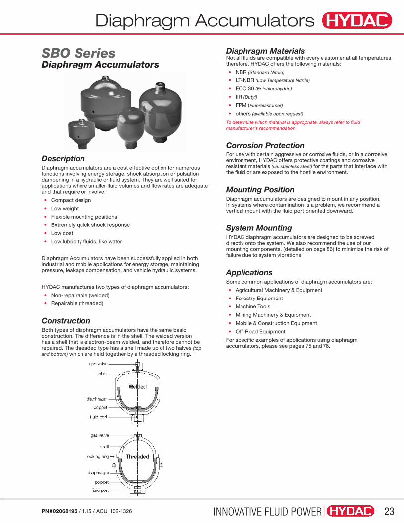
DescriptionDiaphragm accumulators are a cost effective option for numerous functions involving energy storage, shock absorption or pulsation dampening in a hydraulic or fluid system. They are well suited for applications where smaller fluid volumes and flow rates are adequate and that require or involve:
• Compact design
• Low weight
• Flexible mounting positions
• Extremely quick shock response
• Low cost
• Low lubricity fluids, like water
Diaphragm Accumulators have been successfully applied in both industrial and mobile applications for energy storage, maintaining pressure, leakage compensation, and vehicle hydraulic systems.
HYDAC manufactures two types of diaphragm accumulators:
• Non-repairable (welded)
• Repairable (threaded)
ConstructionBoth types of diaphragm accumulators have the same basic construction. The difference is in the shell. The welded version has a shell that is electron-beam welded, and therefore cannot be repaired. The threaded type has a shell made up of two halves (top and bottom) which are held together by a threaded locking ring.
Diaphragm MaterialsNot all fluids are compatible with every elastomer at all temperatures, therefore, HYDAC offers the following materials:
• NBR (Standard Nitrile)
• LT-NBR (Low Temperature Nitrile)
• ECO 30 (Epichlorohydrin)
• IIR (Butyl)
• FPM (Fluorelastomer)
• others (available upon request)
To determine which material is appropriate, always refer to fluid manufacturer’s recommendation.
Corrosion ProtectionFor use with certain aggressive or corrosive fluids, or in a corrosive environment, HYDAC offers protective coatings and corrosive resistant materials (i.e. stainless steel) for the parts that interface with the fluid or are exposed to the hostile environment.
Mounting PositionDiaphragm accumulators are designed to mount in any position. In systems where contamination is a problem, we recommend a vertical mount with the fluid port oriented downward.
System MountingHYDAC diaphragm accumulators are designed to be screwed directly onto the system. We also recommend the use of our mounting components, (detailed on page 86) to minimize the risk of failure due to system vibrations.
ApplicationsSome common applications of diaphragm accumulators are:
• Agricultural Machinery & Equipment
• Forestry Equipment
• Machine Tools
• Mining Machinery & Equipment
• Mobile & Construction Equipment
• Off-Road Equipment
For specific examples of applications using diaphragm accumulators, please see pages 75 and 76.
SBO SeriesDiaphragm Accumulators

Diaphragm Accumulators
INNOVATIVE FLUID POWER24 PN#02068195 / 1.15 / ACU1102-1326
Model Code Model Codes containing RED selections are non-standard items – Contact HYDAC for information and availability Not all combinations are available
SBO 210 - 1 E4 / 112 S – 210 CK XXXSeries SBO XXX = Diaphragm Accumulator (XXX = series designation) (see tables on following pages for most common series and size selections)
Size (in Liters, see tables on dimension pages to follow) 0.075 = 0.075 Liters ...see tables on following pages for complete list of sizes, and which versions they are available in 3.5 = 3.5 Liters
Shell Construction and Gas Port Design E1 = Welded Construction, rechargeable, HYDAC Gas Valve Version 1 (M 28 x 1.5) E2 = Welded Construction, factory precharged and sealed, (not rechargeable) (Not available on SBO330 or on any accumulator larger than 1.4 liters) E4 = Welded Construction, rechargeable, HYDAC Gas Valve Version 4 (8VI-ISO 4570) A6 = Threaded Construction, rechargeable, HYDAC Gas Valve Version 1 (M 28 x 1.5)
Material Code Depending on Application 112 = Standard for oil service (mineral oil)
Fluid Port 1 = Carbon steel 3 = Stainless steel 4 = Chemically plated carbon steel (ONLY WETTED SURFACES for water service) 6 = Low temperature carbon steel (< -20°F)
Shell 0 = Synthetic coated carbon steel (Applied internally & externally for water service) 1 = Carbon steel 2 = Chemically plated carbon steel (internal & external for water service) 4 = Stainless steel (please note: MAWP decreases for most stainless models - see tables) 6 = Low temperature carbon steel (< -20°F)
Diaphragm Compound 2 = NBR (Buna N) 3 = ECO (Hydrin) 4 = IIR (Butyl) 5 = LT-NBR (low temp. Buna) 6 = FPM (fluoroelastomer) 7 = Others (available on request)
Country of Installation S = USA (for other countries see page 3 for proper code designation)
Maximum Working Pressure in bar (see tables on dimension pages to follow) 100 = 1500 psi 140 = 2000 psi 200 = 3000 psi 210 = 3000 psi 250 = 3600 psi 330 = 4700 psi 400 = 5800 psi 450 = 6500 psi 500 = 7200 psi 750 = 10000 psi
Fluid Port Connection AK = BSP connection AB = Male / Female combination connection CK = Standard SAE connection (other fluid ports available upon request — consult factory)
Gas Precharge Pressure (P0) in bar (always required for E2 model gas valve) xxx = 3 digits
Compound Oper. Temp Range Typical Fluids
NBR5˚ to 180˚F mineral oils32˚ to 180˚F water & water-glycols (5% minimum glycol)
Low Temp NBR -50˚ to 180˚F mineral oilsECO...113... -20˚ to 250˚F mineral oilsECO...663... -40˚ to 250˚F mineral oils & water (with low temperature CS shell)IIR -20˚ to 200˚F phosphate esters & brake fluidsFPM 5˚ to 300˚F chlorinated hydrocarbons

Diaphragm Accumulators
INNOVATIVE FLUID POWER 25PN#02068195 / 1.15 / ACU1102-1326
Series Max. p2:p0
Size (L)
Effective Gas Vol
(in3)
MAWP psi/(bar)
Weight lbs/(kg)
A in
(mm)
øD** in
(mm)
Thread-FK-Hex
in(mm)
Q gpm
CK AK AB
(SAE - female) (BSPP - female)
(BSPP - female)
(DIN 13 - male)
SBO 250 8:1 0.075 5 3600(250)
1.5(0.7)
2.68(68.0)
2.52(64.0) 9/16-18 UNF G 1/2 N/A N/A 1.18
(30) 10
SBO 210 8:1 0.16 102600/(180)* 1.8
(0.8)3.15
(80.0)2.91(74.0) 9/16-18 UNF G 1/2 N/A N/A 1.18
(30) 103000/(210)
SBO 210 8:1 0.32 202400/(160)* 2.9
(1.3)3.66
(93.0)3.66
(93.0) 3/4-16 UNF G 1/2 N/A N/A 1.42(36) 25
3000/(210)
SBO 210 8:1 0.5 30 3000(210)
3.7(1.7)
4.35(124.0)
4.13(105.0) 3/4-16 UNF G 1/2 N/A N/A 1.42
(36) 25
SBO 330 8:1 0.6 36 4700(330)
7.3(3.3)
5.04(128.0)
4.53(115.0) 3/4-16 UNF G 1/2 G 1/2 M33 x 1.5 1.42
(36) 25
SBO 210 8:1 0.75 452000/(140)* 6.2
(2.8)4.88
(124.0)4.76
(121.0) 3/4-16 UNF G 1/2 G 1/2 M33 x 1.5 1.42(36) 25
3000/(210)
SBO 330 8:1 0.75 45 4700(330)
8.9(4.0)
4.78(122.0)
4.96(126.0) 3/4-16 UNF G 1/2 G 1/2 M33 x 1.5 1.42
(36) 25
SBO 200 8:1 1 60 3000(210)
7.9(3.6)
5.39(137.0)
5.35(136.0) 3/4-16 UNF G 1/2 G 1/2 M33 x 1.5 1.42
(36) 25
SBO 140 8:1 1.4 85 2000(140)
8.6(3.9)
5.91(150.0)
5.71(145.0) 3/4-16 UNF G 1/2 G 1/2 M33 x 1.5 1.42
(36) 25
SBO 210 8:1 1.4 85 3000(210)
11.9(5.4)
6.14(156.0)
5.91(150.0) 3/4-16 UNF G 1/2 G 1/2 M33 x 1.5 1.42
(36) 25
SBO 330 8:1 1.4 85 4700(330)
16.6(7.5)
6.33(160.0)
6.1(155.0) 3/4-16 UNF G 1/2 G 1/2 M33 x 1.5 1.42
(36) 25
SBO 100 8:1 2 1201500/(100)* 8.8
(4.0)6.57
(167.0)6.3
(160.0) 1 1/16 -12 UNF G 3/4 G 3/4 M45 x 1.5 1.81(46) 40
1500/(100)
SBO 210 8:1 2 120 3000(210)
14.6(6.6)
6.81(173.0)
6.57(167.0) 1 1/16 -12 UNF G 3/4 G 3/4 M45 x 1.5 1.81
(46) 40
SBO 330 8:1 2 120 4700(330)
17.7(8.0)
7.12(180.0)
6.77(172.0) 1 1/16 -12 UNF G 3/4 G 3/4 M45 x 1.5 1.81
(46) 40
SBO 210 4:1 2.8 170 3000(210)
18(8.2)
8.94(227.0)
6.57(167.0) 1 1/16 -12 UNF G 3/4 G 3/4 M45 x 1.5 1.81
(46) 40
SBO 250 4:1 3.5 230 3000(210)
24.6(11.2)
11.14(283.0)
6.69(170.0) 1 1/16 -12 UNF G 3/4 G 3/4 M45 x 1.5 1.81
(46) 40
SBO 330 4:1 3.5 230 4700(330)
30.6(13.8)
10.78(274.0)
6.77(172.0) 1 1/16 -12 UNF G 3/4 G 3/4 M45 x 1.5 1.81
(46) 40
Dimensions are for general information only, all critical dimensions should be verified.Dimensions are in inches/(mm) and lbs/(kg) *Reduced MAWP values for stainless steel models **Diameter at electron beam weld at shell seam may be up to +0.150” larger in diameter
Dimensions Non-Repairable Welded Diaphragm Accumulators
Not available on SBO330 or on any accumulator larger than 1.4 liters, minimum lot size 200pcs.
Diaphragm Accumulators
INNOVATIVE FLUID POWER26 PN#02068195 / 1.15 / ACU1102-1326
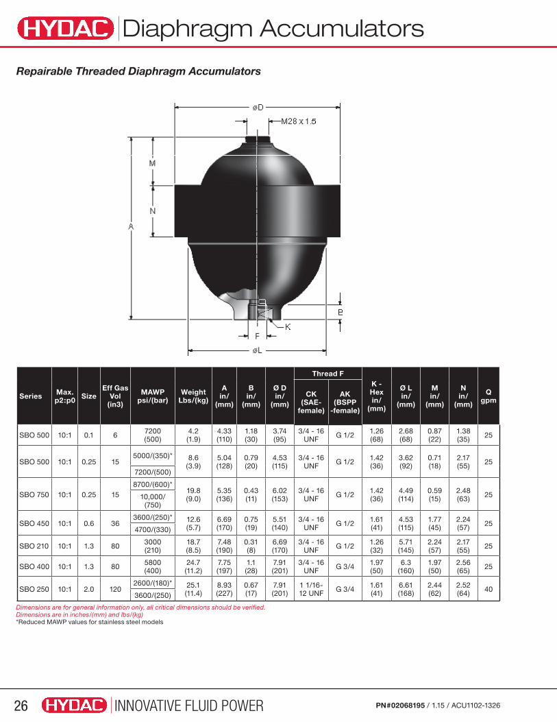
Series Max. p2:p0 Size
Eff Gas Vol
(in3)
MAWP psi/(bar)
Weight Lbs/(kg)
A in/
(mm)
B in/
(mm)
Ø D in/
(mm)
Thread FK - Hex in/
(mm)
Ø L in/
(mm)
M in/
(mm)
N in/
(mm)
Q gpm
CK (SAE-
female)
AK(BSPP
-female)
SBO 500 10:1 0.1 6 7200(500)
4.2(1.9)
4.33(110)
1.18(30)
3.74(95)
3/4 - 16 UNF G 1/2 1.26
(68)2.68(68)
0.87(22)
1.38(35) 25
SBO 500 10:1 0.25 155000/(350)* 8.6
(3.9)5.04(128)
0.79(20)
4.53(115)
3/4 - 16 UNF G 1/2 1.42
(36)3.62(92)
0.71(18)
2.17(55) 25
7200/(500)
SBO 750 10:1 0.25 158700/(600)*
19.8(9.0)
5.35(136)
0.43(11)
6.02(153)
3/4 - 16 UNF G 1/2 1.42
(36)4.49(114)
0.59(15)
2.48(63) 2510,000/
(750)
SBO 450 10:1 0.6 363600/(250)* 12.6
(5.7)6.69(170)
0.75(19)
5.51(140)
3/4 - 16 UNF G 1/2 1.61
(41)4.53(115)
1.77(45)
2.24(57) 25
4700/(330)
SBO 210 10:1 1.3 80 3000(210)
18.7(8.5)
7.48(190)
0.31(8)
6.69(170)
3/4 - 16 UNF G 1/2 1.26
(32)5.71(145)
2.24(57)
2.17(55) 25
SBO 400 10:1 1.3 80 5800(400)
24.7(11.2)
7.75(197)
1.1(28)
7.91(201)
3/4 - 16 UNF G 3/4 1.97
(50)6.3
(160)1.97(50)
2.56(65) 25
SBO 250 10:1 2.0 1202600/(180)* 25.1
(11.4)8.93(227)
0.67(17)
7.91(201)
1 1/16-12 UNF G 3/4 1.61
(41)6.61(168)
2.44(62)
2.52(64) 40
3600/(250)
Repairable Threaded Diaphragm Accumulators
Dimensions are for general information only, all critical dimensions should be verified.Dimensions are in inches/(mm) and lbs/(kg) *Reduced MAWP values for stainless steel models
Diaphragm Accumulators
INNOVATIVE FLUID POWER 27PN#02068195 / 1.15 / ACU1102-1326
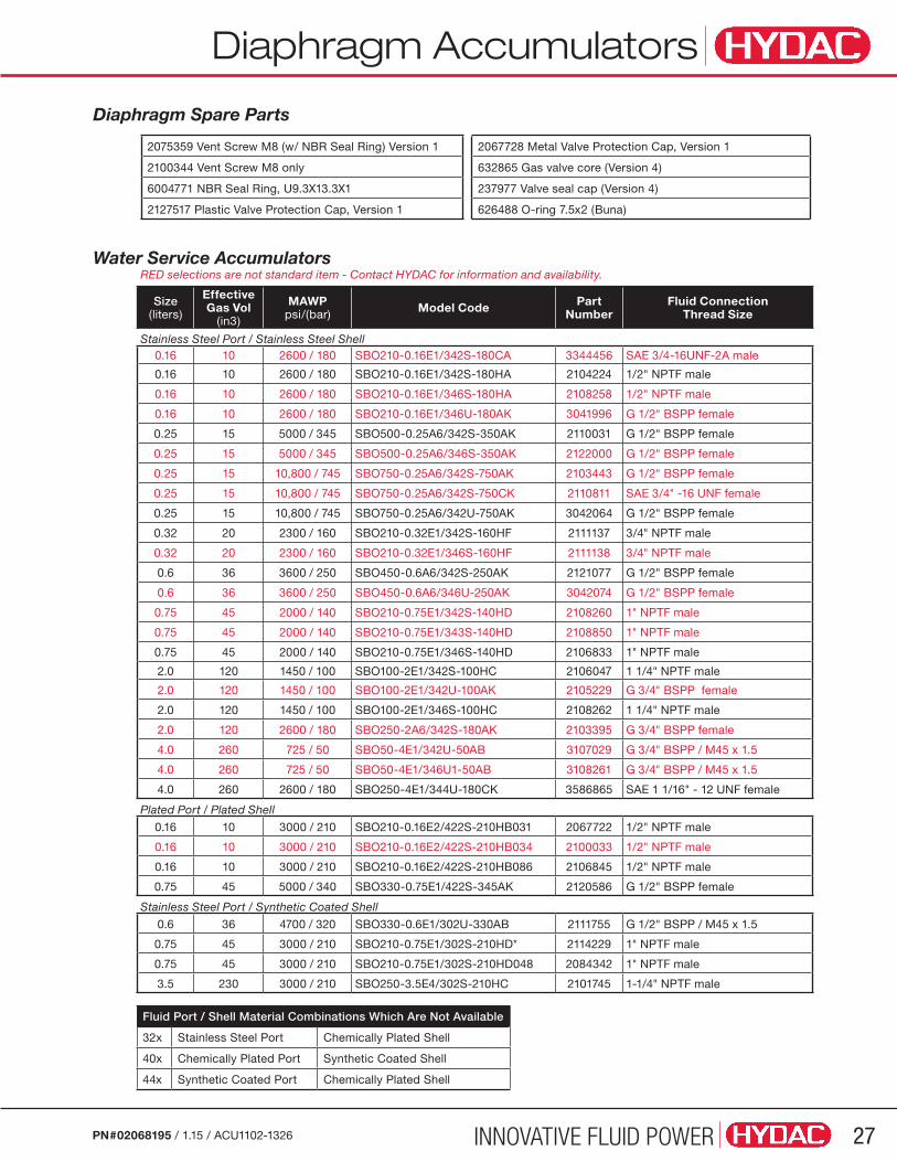
Diaphragm Spare Parts
Water Service AccumulatorsRED selections are not standard item - Contact HYDAC for information and availability.
Size(liters)
EffectiveGas Vol
(in3)
MAWPpsi/(bar) Model Code Part
NumberFluid Connection
Thread Size
Stainless Steel Port / Stainless Steel Shell0.16 10 2600 / 180 SBO210-0.16E1/342S-180CA 3344456 SAE 3/4-16UNF-2A male
0.16 10 2600 / 180 SBO210-0.16E1/342S-180HA 2104224 1/2" NPTF male
0.16 10 2600 / 180 SBO210-0.16E1/346S-180HA 2108258 1/2" NPTF male
0.16 10 2600 / 180 SBO210-0.16E1/346U-180AK 3041996 G 1/2" BSPP female
0.25 15 5000 / 345 SBO500-0.25A6/342S-350AK 2110031 G 1/2" BSPP female
0.25 15 5000 / 345 SBO500-0.25A6/346S-350AK 2122000 G 1/2" BSPP female
0.25 15 10,800 / 745 SBO750-0.25A6/342S-750AK 2103443 G 1/2" BSPP female
0.25 15 10,800 / 745 SBO750-0.25A6/342S-750CK 2110811 SAE 3/4" -16 UNF female
0.25 15 10,800 / 745 SBO750-0.25A6/342U-750AK 3042064 G 1/2" BSPP female
0.32 20 2300 / 160 SBO210-0.32E1/342S-160HF 2111137 3/4" NPTF male
0.32 20 2300 / 160 SBO210-0.32E1/346S-160HF 2111138 3/4" NPTF male
0.6 36 3600 / 250 SBO450-0.6A6/342S-250AK 2121077 G 1/2" BSPP female
0.6 36 3600 / 250 SBO450-0.6A6/346U-250AK 3042074 G 1/2" BSPP female
0.75 45 2000 / 140 SBO210-0.75E1/342S-140HD 2108260 1" NPTF male
0.75 45 2000 / 140 SBO210-0.75E1/343S-140HD 2108850 1" NPTF male
0.75 45 2000 / 140 SBO210-0.75E1/346S-140HD 2106833 1" NPTF male
2.0 120 1450 / 100 SBO100-2E1/342S-100HC 2106047 1 1/4" NPTF male
2.0 120 1450 / 100 SBO100-2E1/342U-100AK 2105229 G 3/4" BSPP female
2.0 120 1450 / 100 SBO100-2E1/346S-100HC 2108262 1 1/4" NPTF male
2.0 120 2600 / 180 SBO250-2A6/342S-180AK 2103395 G 3/4" BSPP female
4.0 260 725 / 50 SBO50-4E1/342U-50AB 3107029 G 3/4" BSPP / M45 x 1.5
4.0 260 725 / 50 SBO50-4E1/346U1-50AB 3108261 G 3/4" BSPP / M45 x 1.5
4.0 260 2600 / 180 SBO250-4E1/344U-180CK 3586865 SAE 1 1/16" - 12 UNF female
Plated Port / Plated Shell
0.16 10 3000 / 210 SBO210-0.16E2/422S-210HB031 2067722 1/2" NPTF male
0.16 10 3000 / 210 SBO210-0.16E2/422S-210HB034 2100033 1/2" NPTF male
0.16 10 3000 / 210 SBO210-0.16E2/422S-210HB086 2106845 1/2" NPTF male
0.75 45 5000 / 340 SBO330-0.75E1/422S-345AK 2120586 G 1/2" BSPP female
Stainless Steel Port / Synthetic Coated Shell
0.6 36 4700 / 320 SBO330-0.6E1/302U-330AB 2111755 G 1/2" BSPP / M45 x 1.5
0.75 45 3000 / 210 SBO210-0.75E1/302S-210HD* 2114229 1" NPTF male
0.75 45 3000 / 210 SBO210-0.75E1/302S-210HD048 2084342 1" NPTF male
3.5 230 3000 / 210 SBO250-3.5E4/302S-210HC 2101745 1-1/4" NPTF male
2075359 Vent Screw M8 (w/ NBR Seal Ring) Version 1
2100344 Vent Screw M8 only
6004771 NBR Seal Ring, U9.3X13.3X1
2127517 Plastic Valve Protection Cap, Version 1
Fluid Port / Shell Material Combinations Which Are Not Available
32x Stainless Steel Port Chemically Plated Shell
40x Chemically Plated Port Synthetic Coated Shell
44x Synthetic Coated Port Chemically Plated Shell
2067728 Metal Valve Protection Cap, Version 1
632865 Gas valve core (Version 4)
237977 Valve seal cap (Version 4)
626488 O-ring 7.5x2 (Buna)
INNOVATIVE FLUID POWER28 PN#02068195 / 1.15 / ACU1102-1326
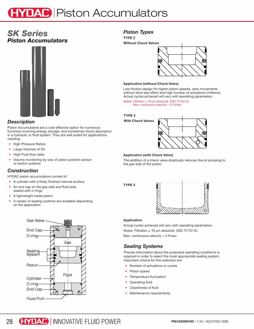
SK SeriesPiston Accumulators
Piston TypesTYPE 2
Without Check Valves
DescriptionPiston Accumulators are a cost effective option for numerous functions involving energy storage, and sometimes shock absorption in a hydraulic or fluid system. They are well suited for applications needing:
• High Pressure Ratios
• Large Volumes of Oil
• High Fluid flow rates
• Volume monitoring by way of piston position sensor or switch systems
ConstructionHYDAC piston accumulators consist of:
• A cylinder with a finely finished internal surface
• An end cap on the gas side and fluid side, sealed with o-rings
• A lightweight metal piston
• A variety of sealing systems are available depending on the application
Piston Accumulators
Application (without Check Valve)
Low-friction design for higher piston speeds, slow movements without stick-slip effect and high number of actuations (millions). Actual cycles achieved will vary with operating parameters.Notes: Filtration ≤ 10 µm absolute. (ISO 17/15/12)
Max. continuous velocity = 12 ft/sec
Application
Actual cycles achieved will vary with operating parameters.
Notes: Filtration ≤ 10 µm absolute. (ISO 17/15/12)
Max. continuous velocity = 3 ft/sec
Application (with Check Valve)
The addition of a check valve drastically reduces the oil pumping to the gas side of the piston.
TYPE 3
Sealing SystemsPrecise information about the proposed operating conditions is required in order to select the most appropriate sealing system. Important criteria for this selection are:
• Number of actuations or cycles
• Piston speed
• Temperature fluctuation
• Operating fluid
• Cleanliness of fluid
• Maintenance requirements
TYPE 2
With Check Valves

INNOVATIVE FLUID POWER 29PN#02068195 / 1.15 / ACU1102-1326
Seal MaterialsThe following sealing elastomers are available, depending on the operating conditions:
• NBR (acrylic nitrile butadiene rubber)
• FPM (fluoro-elastomer)
• PUR (polyurethane)Suitable materials are also available for low temperature applications.
Fluids The following sealing materials are suitable for the fluids listed below:
NBR, resistant to:
• Mineral Oils (HL and HLP)
• Non-flammable fluids from groups HFA, HFB, and HFC
• Water and seawater up to approx. 100ºC
NBR, not resistant to
• Aromatic hydrocarbons
• Chlorinated hydrocarbons
• Amines and ketones
• Hydraulic fluids from the HFD Groups
FPM, resistant to:
• Mineral Oils (HL and HLP)
• Hydraulic fluids from the HFD Groups
• Fuels as well as aromatic and chlorinated hydrocarbons
• Inorganic acids (but not all, please contact HYDAC)
FPM not resistant to:
• Ketones and amines
• (Anhydrous) ammonia
• Organic acids such as formic acid and acetic acid
PUR resistant to:
• Mineral Oils (HL and HLP)
• Non-flammable fluids from the HFA group
PUR not resistant to:
• Water and water-gylcol mixtures
• Alkalis
• Acids
Corrosion ProtectionFor use with certain aggressive or corrosive fluids, or in a corrosive environment, HYDAC offers protective coatings and corrosive resistant materials (i.e. stainless steel) for the accumulator parts that come in contact with the fluid, or are exposed to the hostile environment.
System MountingHYDAC piston accumulators may operate in any position. Vertical installation is preferable with the gas side up. We recommend the use of our mounting components, which are detailed on page 86, to minimize risk of failure due to system vibrations.
Effects of Seal FrictionThe permissible piston velocity depends on the sealing friction. Higher piston velocities are possible where there is less sealing friction.
Piston Accumulators
Graph 1: Traditional piston designs
Graph 2: Piston Type 2 and Type 3 (low friction model)
Stick-Slip Effect
HYDAC piston accumulators with low friction piston seals allow continuous operating velocities of up to 12 ft/sec with short bursts, up to 15 ft/sec (see type 2 piston).
Small pressure differentials between gas and oil side improve the effectiveness of HYDAC piston accumulators. To emphasize the friction effect on the pressure curve during an accumulation cycle, measurements with various sealing systems are illustrated.
The measurement graphs below are a true representation of the gas and oil pressure of piston accumulators with different sealing systems. The comparison of these two measurements clearly shows the difference in the pressure differential between gas and oil side:
Graph 1: ∆p max. ≈ 125 psi
Graph 2: ∆p max. ≈ 14.5 psi
The effect of the sealing friction on the working pressure is particularly striking in traditional piston designs. Abrupt piston movements (the stick-slip effect) are caused by the seal friction as shown in Graph 1. The low sealing friction of HYDAC type 2 pistons drastically reduces the stick-slip effect therefore maximizing piston responsiveness.
Advantages of Using the Low-friction Sealing System (type 2):• Minimum friction.
• Suitable for low pressure differentials.
• No start-up friction, no stick-slip.
• Low noise, no vibration.
• High piston speeds up to 12 ft/sec continuous.
• Improved accumulator efficiency.
• High life expectancy, low maintenance requirements.

INNOVATIVE FLUID POWER30 PN#02068195 / 1.15 / ACU1102-1326
Piston Accumulators
Advantages of HYDAC Piston Accumulators• Complete size range from 1 qt. to 100 gallons nominal volume.
• High ratios possible between precharge pressure and maximum working pressure.
• High flow rates - up to 4700 gpm from one accumulator.
• Power savings.
• Gas-proof and leak-free.
• No sudden discharge of gas when seal is worn.
• Space efficient.
• Piston location monitoring available.
SK 210 Series (Non-ASME) 3000 psi Advantages The piston accumulator series SK210 & 250 are an intermediate bore diameter with repairable design. They are HYDAC certified, designed in accordance with ASME pressure code. Features of this series are:
• Bore Diameter up to 6” ID
• Sizes from 1 quart to 15 gallons
• Largest range of standard models for quick delivery times
• Military Style Gas Valve MS28889-2 / M6164-2, repairable
Application • Mobile Hydraulic
• Industrial Hydraulic
SK 250 Series (Non-ASME) 3600 psi Advantages The piston accumulator series SK350 are an intermediate bore diameter with repairable design. They are HYDAC certified, designed in accordance with ASME pressure code. Features of this series are:
• Bore Diameter up to 6” ID
• Sizes from 1 quart to 15 gallons
• Largest range of standard models for quick delivery times
• Military Style Gas Valve MS28889-2 / M6164-2, repairable
Application • Mobile Hydraulic
• Industrial Hydraulic
SK 280 Series (Non-ASME) 4000 psi Advantages The piston accumulator series SK280 is a weight optimized, non-repairable design. The non-repairable design and special production process of these HYDAC accumulators save cost, making this series an economic option.
• Cost-effective – due to the non-repairable design and an optimized production process
• Weight reduced series
• Reduced installation space
• Standard-gas valve (HYDAC Version 1) with integrated
M28x1.5 male thread
• Quick delivery for models with standard connection
• SAE fluid ports are available
• PED/CE pressure code certification
Application • Mobile Hydraulic
• Weight Sensitive Industrial Hydraulic
SK 350 Series (Non-ASME) 5000 psi Advantages The piston accumulator series SK350 are an intermediate bore diameter with repairable design. They are HYDAC certified, designed in accordance with ASME pressure code. Features of this series are:
• Bore Diameter up to 6” ID
• Sizes from 1 quart to 15 gallons
• Largest range of standard models for quick delivery times
• Military Style Gas Valve MS28889-2 / M6164-2, repairable
Application • Mobile Hydraulic
• Industrial Hydraulic
SK 350(ASME) 3000 psiSK 600 Series (ASME) 5000 psiAdvantages The piston accumulator series SK350 & 600 is HYDAC’s most versatile series with a repairable design and large selection of options. The largest range of possible sizes, material construction, and other options are offered. Standard and Low Friction piston designs are available for superior performance and flow rates. Features of this series are:
• Bore Diameters from 2.4” ID to 19.3” ID
• Sizes from 1 quart to 200 gallons
• Largest range of possible sizes and material options
• Standard and Low Friction piston designs available
• Largest variety of gas and fluid port options
• A variety of piston position sensor monitoring systems are available
• ASME, CRN, PED/CE and other pressure code certifications are available
Application • Heavy Mobile Hydraulic
• Industrial Hydraulic
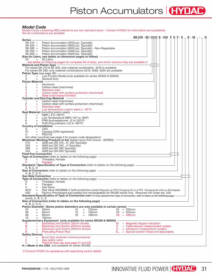
Accumulators
INNOVATIVE FLUID POWER 31PN#02068195 / 1.15 / ACU1102-1326
Model Code Model Codes containing RED selections are non-standard items – Contact HYDAC for information and availability Not all combinations are available
SK 210 - 20 / 2112 S - 210 F C F - V E - 18 - H Series SK 210 = Piston Accumulator (3000 psi, Typically) SK 250 = Piston Accumulator (3600 psi, Typically) SK 280 = Piston Accumulator (4000 psi, Typically) - Non-Repairable SK 350 = Piston Accumulator (3000 psi, Typically) SK 600 = Piston Accumulator (5000 psi, Typically)Size (in Liters, see tables on dimension pages to follow) 20 = 20 Liters ...see tables on following pages for complete list of sizes, and which versions they are available inMaterial and Piston Type For series SK 210 & SK 250, only material combination 3218 is available For series SK 280, only material combinations 3218, 3268, 3265 are availablePiston Type (see page 38) 2 = Low Friction Model (only available for series SK350 & SK600) 3 = General DutyPiston Material 1 = Aluminum 2 = Carbon steel (machined) 3 = Stainless steel 4 = Carbon steel with surface protection (machined) 5 = Steel (cold impact formed)Cylinder and End Cap Material 1 = Carbon steel (machined) 2 = Carbon steel with surface protection (machined) 3 = Stainless steel 6 = Low temperature carbon steel (< -20°F)Seal Material (including piston seals) 2 = NBR (-4 to 180ºF) 5 = Low Temperature NBR (-50º to 180F) 6 = FPM fluoroelastomer (5 to 320ºF) 8 = PUR Polyurethane (-22 to 180ºF)Country of Installation S = USA S1 = Canada (CRN registered) U = PED/CE (for other countries see page 3 for proper code designation)Maximum Working Pressure in bar (based upon first choice - SERIES) 210 = 3000 psi (SK 210…H, 350 Typically) 250 = 3600 psi (SK 250…H Typically) 280 = 4000 psi (SK 280 Typically) 345 = 5000 psi (SK 600 Typically)Fluid Port ConnectionType of Connection (refer to tables on the following page) A = Threaded, Female F = FlangedStandard / Specification of Type of Connection (refer to tables on the following page) A, B, C, DSize of Connection (refer to tables on the following page) A, B, C, D, E, ...Gas Side ConnectionType of Connection (refer to tables on the following page) A = Threaded, Female F = Flanged V = Gas Valve KCH = Gas Valve MS28889-2 (with protective cover) Requires an FPO Charging Kit or a FPK Charging Kit with an A9 Adapter 000 = Factory Precharged and sealed (not rechargeable) for SK280 series only. Required min order qty. 200Standard/Specification of Type of Connection (OMIT if V was selected from Type of Connection, refer to tables on the following page) (omit), A, B, C, DSize of Connection (refer to tables on the following page) A, B, C, D, E, ...Piston Diameter (Some piston diameters are only available in certain series) 05 = 50mm 12 = 125mm 25 = 250mm 06 = 60mm 15 = 150mm 35 = 355mm 08 = 80mm 18 = 180mm 49 = 490mm 10 = 100mm Supplementary Equipment (only available for series SK350 & SK600) A = Electrical Limit Switch (35mm stroke) M = Magnetic flapper indication B = Electrical Limit Switch (200mm stroke) S = Cable tension measurement system C = Electrical Limit Switch (500mm stroke) U = Ultrasonic measurement system K = Protruding Piston Rod E... = Special switch1 (fixed and adjustable)Safety Devices 1 = Burst Disc (indicate nominal pressure) 2 = Gas safety valve 3 = Thermal fuse cap (see page 51 and 52)H = Made in the USA (not available for series SK280)
1) Consult HYDAC for assistance with specifying switch details
Piston Accumulators

INNOVATIVE FLUID POWER32 PN#02068195 / 1.15 / ACU1102-1326
Connections SK 210 & SK 250 Series (Non-ASME)
Model Code Support Tables for Fluid ConnectionsFemale Threaded Connections: A Sample Code = A1 C2 K3 4” 6”
Code Type of Connection A B C D E F G H J K L M
CANSI B1.1 (UN..-2B)Seal SAE J 514
SAE-25/16-
24UNF
SAE-33/8-
24UNF
SAE-47/16-
20UNF
SAE-51/2-
20UNF
SAE-69/16-
18UNF
SAE-83/4-
16UNF
SAE-107/8-
14UNF
SAE-121 1/16-12UN
SAE-141 3/16-12UN
SAE-161 5/16-12UN
SAE-201 5/812UN
SAE-241 7/812UN
DNPT (ANSI B1.20.3)
1/16-27 1/8-27 1/4-18 3/8-18 1/2-14 3/4-14 1-11 1/2 1 1/4-11 1/2
1 1/2-11 1/2
2 1/2-11 1/2 2 1/2-8 n/a
Note: Bold copy indicates standard size.1) use “A” as the first character of the connection code for all Female Threaded Connections.2) Enter the letter of the ROW (red) as the second character of the connection code.3) Enter the letter of the COLUMN (gray) as the third character of the connection code.
Flange Connections: F4 Sample Code = F4 C5 E6
Code Type of Connection A B C D E F
C SAE Code 61 (3000 psi) 1/2” 3/4” 1” 1 1/4” 1 1/2” 2”
4) Use “F” as the first character of the connection code for all Flange Connections.5) Use “C” as the second character of the connection code for all flange connections.6) Enter the letter of the COLUMN (gray) as the third character of the connection code.
Maximum Working Pressure - 3000 PSI Operating Temperature - 14ºF to 180ºF Standard Seal for Petroleum-Based Oils - Polyurethane Military Style Gas Valve - MS28889-2 / M6164-2Paint - Black PrimerPre-Charge - None
Maximum Working Pressure 3000 PSI
Operating Temperature 14ºF to 180ºF
Standard Seal for Petroleum-Based Oils Polyurethane
Military Style Gas Valve MS28889-2 / M6164-2
Paint Black Primer
Pre-Charge None
SeriesNominal
Sizegal.
Eff Gas Volume
(Vo)in3 / L
Weightlbs / kg
Ain / mm
øD1in / mm
øD2in / mm
SK 210
0.25 77.5 / 1.27 38 / 17 18 / 457 4 / 100 4.92 / 125
0.5 138 / 2.27 50 / 23 22 / 569 4 / 100 4.92 / 125
1 260 / 4.27 71 / 32 31 / 791 4 / 100 4.92 / 125
2 504 / 8.27 107 / 49 45 / 1131 4 / 100 4.92 / 125
1 294 / 4.82 94.7 / 43 17.1 / 435 6 / 150 6.89 / 175
1.5 416 / 6.82 107.4 / 48.8 21.7 / 550 6 / 150 6.89 / 175
2.5 660 / 10.82 132 / 60.1 30.5 / 775 6 / 150 6.89 / 175
5 1270 / 20.82 1945 / 88.4
52.8 / 1340 6 / 150 6.89 / 175
7.5 1759 / 28.82 245.2 / 111.4
70.9 / 1800 6 / 150 6.89 / 175
10 2491 / 40.82 319.6 / 145.3
97.4 / 2475 6 / 150 6.89 / 175
SK 250
1 294 / 4.82 112 / 51 18 / 451 6 / 150 6.89 / 175
1.5 416 / 6.82 125 / 57 22 / 566 6 / 150 6.89 / 175
2.5 660 / 10.82 150 / 68 31 / 791 6 / 150 6.89 / 175
5 1270 / 20.82 215 / 98 53 / 1358 6 / 150 6.89 / 175
7.5 1759 / 28.82 269 / 122 72 / 1836 6 / 150 6.89 / 175
10 2491 / 40.82 344 / 156 98 / 2491 6 / 150 6.89 / 175
4” Clamp Part Number 444505 see page 71 6” Clamp Part Number 3627520 see page 71
Dimensions SK 210 & SK 250 Series (Non-ASME)
Piston Accumulators

INNOVATIVE FLUID POWER 33PN#02068195 / 1.15 / ACU1102-1326
Maximum Working Pressure - 3000 PSI Operating Temperature - 14ºF to 180ºF Standard Seal for Petroleum-Based Oils - Polyurethane Military Style Gas Valve - MS28889-2 / M6164-2Paint - Black PrimerPre-Charge - None
Seal Kits
Piston Diameter *Piston Seal Kits
10 (100 mm) Rebuild Kit SK210..10 /2123414
15 (150 mm) Rebuild Kit SK210..15 /3145418
*Includes the following End Cap O-rings (2) Guide Ring (1) Center Seal (1)
(number of components)
Replacement Gas ValveModel Code: GAS VALVE M6164-2 W/CAP
Part Number : 2054712
Seals Included with Piston Seal Kit
Diameter Seal Assembly Piston Insertion
10 (100mm) 00352198 00290056
15 (150mm) 02124157 02124161
Replacement Pistons
Piston Diameter Replacement Piston PN
10 (100 mm) 2115547
15 (150 mm) 3016231
Tools
Standard Product OfferingNom. Size (gal.)
øD1 (in Nom.) / (mm)
Fluid Port Model Code Max Working Pressure (psi)
0.25 4 / (100) SAE-20 (1 5/8-12 UN) SK210-1/3218S-210-ACL-KCH-10HP 3000
0.50 4 / (100) SAE-20 (1 5/8-12 UN) SK210-2/3218S-210-ACL-KCH-10HP 3000
1 4 / (100) SAE-20 (1 5/8-12 UN) SK210-4/3218S-210-ACL-KCH-10HP 3000
2 4 / (100) SAE-20 (1 5/8-12 UN) SK210-8/3218S-210-ACL-KCH-10HP 3000
1 6 / (150) SAE-24 (1 7/8-12 UN) SK210-4/3218S-210ACM-KCH-15HP 3000
1.5 6 / (150) SAE-24 (1 7/8-12 UN) SK210-6/3218S-210ACM-KCH-15HP 3000
2.5 6 / (150) SAE-24 (1 7/8-12 UN) SK210-10/3218S-210ACM-KCH-15HP 3000
5 6 / (150) SAE-24 (1 7/8-12 UN) SK210-20/3218S-210ACM-KCH-15HP 3000
7.5 6 / (150) SAE-24 (1 7/8-12 UN) SK210-28/3218S-210ACMKCH-15HP 3000
10 6 / (150) SAE-24 (1 7/8-12 UN) SK210-40/3218S-210ACM-KCH-15HP 3000
Piston Accumulators
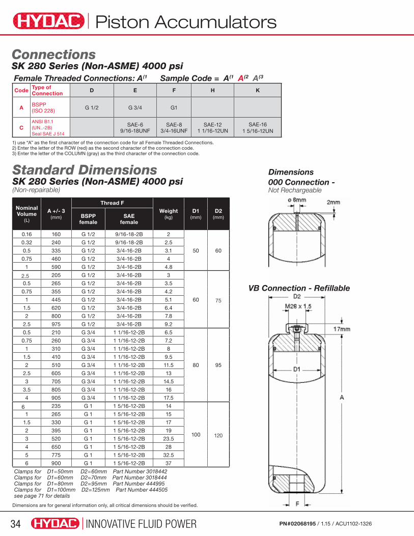
INNOVATIVE FLUID POWER34 PN#02068195 / 1.15 / ACU1102-1326
Nominal Volume
(L)
A +/- 3 (mm)
Thread FWeight
(kg)D1
(mm)D2
(mm)BSPPfemale
SAEfemale
0.16 160 G 1/2 9/16-18-2B 2
50 60
0.32 240 G 1/2 9/16-18-2B 2.5
0.5 335 G 1/2 3/4-16-2B 3.1
0.75 460 G 1/2 3/4-16-2B 4
1 590 G 1/2 3/4-16-2B 4.8
2.5 205 G 1/2 3/4-16-2B 3
60 75
0.5 265 G 1/2 3/4-16-2B 3.5
0.75 355 G 1/2 3/4-16-2B 4.2
1 445 G 1/2 3/4-16-2B 5.1
1.5 620 G 1/2 3/4-16-2B 6.4
2 800 G 1/2 3/4-16-2B 7.8
2.5 975 G 1/2 3/4-16-2B 9.2
0.5 210 G 3/4 1 1/16-12-2B 6.5
80 95
0.75 260 G 3/4 1 1/16-12-2B 7.2
1 310 G 3/4 1 1/16-12-2B 8
1.5 410 G 3/4 1 1/16-12-2B 9.5
2 510 G 3/4 1 1/16-12-2B 11.5
2.5 605 G 3/4 1 1/16-12-2B 13
3 705 G 3/4 1 1/16-12-2B 14.5
3.5 805 G 3/4 1 1/16-12-2B 16
4 905 G 3/4 1 1/16-12-2B 17.5
6 235 G 1 1 5/16-12-2B 14
100 120
1 265 G 1 1 5/16-12-2B 15
1.5 330 G 1 1 5/16-12-2B 17
2 395 G 1 1 5/16-12-2B 19
3 520 G 1 1 5/16-12-2B 23.5
4 650 G 1 1 5/16-12-2B 28
5 775 G 1 1 5/16-12-2B 32.5
6 900 G 1 1 5/16-12-2B 37
Clamps for D1=50mm D2=60mm Part Number 3018442Clamps for D1=60mm D2=70mm Part Number 3018444 Clamps for D1=80mm D2=95mm Part Number 444995 Clamps for D1=100mm D2=125mm Part Number 444505 see page 71 for details
Dimensions are for general information only, all critical dimensions should be verified.
Dimensions 000 Connection - Not Rechargeable
VB Connection - Refillable
Standard Dimensions SK 280 Series (Non-ASME) 4000 psi(Non-repairable)
Connections SK 280 Series (Non-ASME) 4000 psiFemale Threaded Connections: A(1 Sample Code = A(1 A(2 A(3
Code Type of Connection D E F H K
A BSPP(ISO 228) G 1/2 G 3/4 G1
CANSI B1.1(UN..-2B)Seal SAE J 514
SAE-69/16-18UNF
SAE-83/4-16UNF
SAE-121 1/16-12UN
SAE-161 5/16-12UN
1) use “A” as the first character of the connection code for all Female Threaded Connections.2) Enter the letter of the ROW (red) as the second character of the connection code.3) Enter the letter of the COLUMN (gray) as the third character of the connection code.
Piston Accumulators
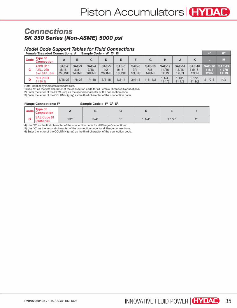
INNOVATIVE FLUID POWER 35PN#02068195 / 1.15 / ACU1102-1326
Connections SK 350 Series (Non-ASME) 5000 psi
Model Code Support Tables for Fluid ConnectionsFemale Threaded Connections: A Sample Code = A1 C2 K3 4” 6”
Code Type of Connection A B C D E F G H J K L M
CANSI B1.1 (UN..-2B)Seal SAE J 514
SAE-25/16-
24UNF
SAE-33/8-
24UNF
SAE-47/16-
20UNF
SAE-51/2-
20UNF
SAE-69/16-
18UNF
SAE-83/4-
16UNF
SAE-107/8-
14UNF
SAE-121 1/16-12UN
SAE-141 3/16-12UN
SAE-161 5/16-12UN
SAE-201 5/812UN
SAE-241 7/812UN
DNPT (ANSI B1.20.3)
1/16-27 1/8-27 1/4-18 3/8-18 1/2-14 3/4-14 1-11 1/2 1 1/4-11 1/2
1 1/2-11 1/2
2 1/2-11 1/2 2 1/2-8 n/a
Note: Bold copy indicates standard size.1) use “A” as the first character of the connection code for all Female Threaded Connections.2) Enter the letter of the ROW (red) as the second character of the connection code.3) Enter the letter of the COLUMN (gray) as the third character of the connection code.
Flange Connections: F4 Sample Code = F4 C5 E6
Code Type of Connection A B C D E F
C SAE Code 61 (3000 psi) 1/2” 3/4” 1” 1 1/4” 1 1/2” 2”
4) Use “F” as the first character of the connection code for all Flange Connections.5) Use “C” as the second character of the connection code for all flange connections.6) Enter the letter of the COLUMN (gray) as the third character of the connection code.
Piston Accumulators
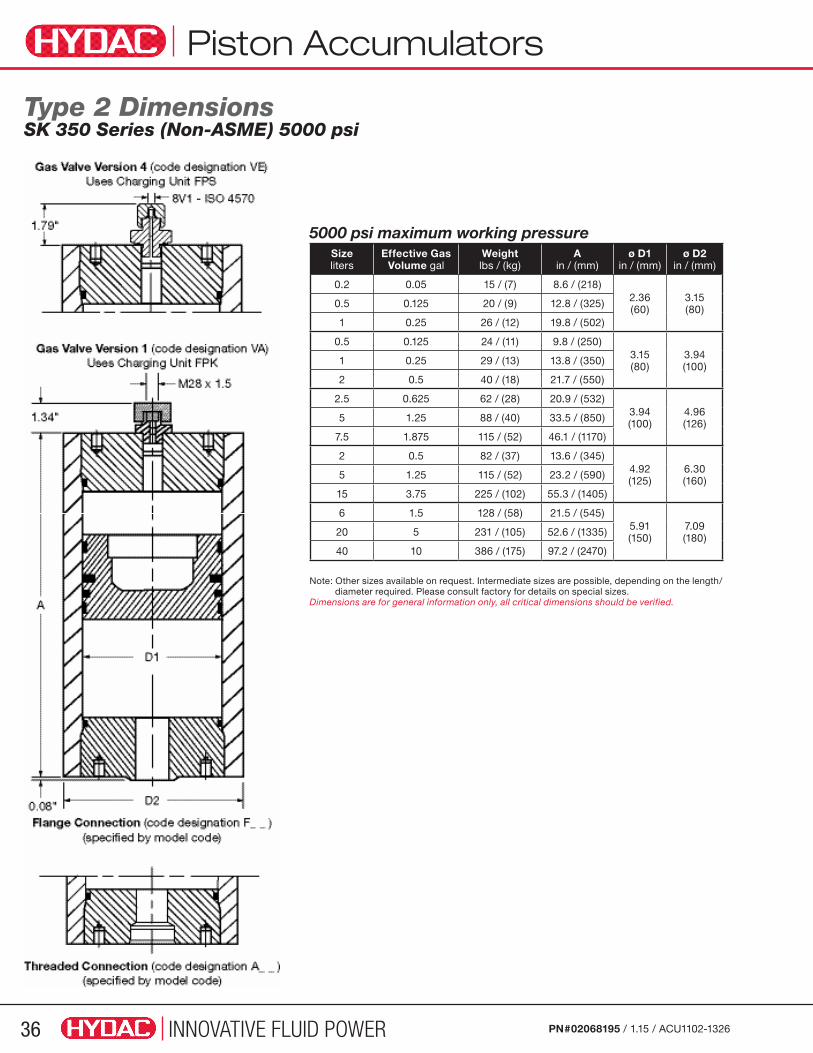
INNOVATIVE FLUID POWER36 PN#02068195 / 1.15 / ACU1102-1326
Piston Accumulators
Size liters
Effective Gas Volume gal
Weight lbs / (kg)
A in / (mm)
ø D1 in / (mm)
ø D2 in / (mm)
0.2 0.05 15 / (7) 8.6 / (218)2.36(60)
3.15(80)0.5 0.125 20 / (9) 12.8 / (325)
1 0.25 26 / (12) 19.8 / (502)
0.5 0.125 24 / (11) 9.8 / (250)3.15(80)
3.94(100)1 0.25 29 / (13) 13.8 / (350)
2 0.5 40 / (18) 21.7 / (550)
2.5 0.625 62 / (28) 20.9 / (532)3.94(100)
4.96(126)5 1.25 88 / (40) 33.5 / (850)
7.5 1.875 115 / (52) 46.1 / (1170)
2 0.5 82 / (37) 13.6 / (345)4.92(125)
6.30(160)5 1.25 115 / (52) 23.2 / (590)
15 3.75 225 / (102) 55.3 / (1405)
6 1.5 128 / (58) 21.5 / (545)5.91(150)
7.09(180)20 5 231 / (105) 52.6 / (1335)
40 10 386 / (175) 97.2 / (2470)
5000 psi maximum working pressure
Note: Other sizes available on request. Intermediate sizes are possible, depending on the length/diameter required. Please consult factory for details on special sizes.
Dimensions are for general information only, all critical dimensions should be verified.
Type 2 Dimensions SK 350 Series (Non-ASME) 5000 psi
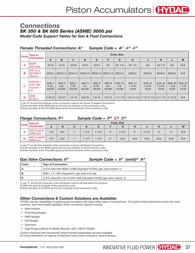
Accumulators
INNOVATIVE FLUID POWER 37PN#02068195 / 1.15 / ACU1102-1326
Piston Accumulators
Other Connections & Custom Solutions are Available:HYDAC has the capabilities to produce accumulators with many other types of connections. The options listed above are simply the most common, and most readily available. Other connection options include:
• Male threads
• Protruding flanges
• ANSI flanges
• DIN flanges
• Autoclave
• High Pressure Block FLANGE (Rexroth, AVIT, HAVIT) PN320
Custom solutions that incorporate valve/manifold assemblies are also available, for more information on special connections and custom solutions, consult factory.
Code Type of Connection
Code, Size
A B C D E F G H J K L M
A BSPP(ISO 228) G1/8 G1/4 G3/8 G1/2 G3/4 G1 G1 1/4 G1 1/2 G2 G2 1/2 G3 N/A
BDIN 13 orISO 965/1 (Metric)
M10x1 M12x1.5 M14x1.5 M16x1.5 M18x1.5 M22x1.5 M27x2 M33x2 M42x2 M48x2 M60x2 N/A
C
ANSI B1.1 (UN..-2B)Seal SAE J 514
SAE-25/16-
24UNF
SAE-33/8-
24UNF
SAE-47/16-
20UNF
SAE-51/2-
20UNF
SAE-69/16-
18UNF
SAE-83/4-
16UNF
SAE-107/8-
14UNF
SAE-121 1/16-12UN
SAE-141 3/16-12UN
SAE-161 5/16-12UN
SAE-201 5/812UN
SAE-241 7/812UN
D ANSI B1.20.3 1/16-27 1/8-27 1/4-18 3/8-18 1/2-14 3/4-14 1-11 1/2 1 1/4-11 1/2 1 1/2-11 1/2 2-11 1/2 2 1/2-8 N/A
1) use “A” as the first character of the connection code for all Female Threaded Connections.2) Enter the letter of the ROW (red) as the second character of the connection code.3) Enter the letter of the COLUMN (gray) as the third character of the connection code.
Female Threaded Connections: A(1 Sample Code = A(1 A(2 A(3
4) use “F” as the first character of the connection code for all Flange Connections.5) Enter the letter of the ROW (red) as the second character of the connection code.6) Enter the letter of the COLUMN (gray) as the third character of the connection code.
Flange Connections: F(4 Sample Code = F(4 C(5 B(6
Code Type of Connection
Code, Size
A B C D E F G H J K L M
C SAE Code 61 (3000 psi) 1/2” 3/4” 1” 1 1/4” 1 1/2” 2” 2 1/2” 3” 3 1/2” 4” 5” N/A
D SAE Code 62 (6000 psi) 1/2” 3/4” 1” 1 1/4” 1 1/2” 2” N/A N/A N/A N/A N/A N/A
7) use “V” as the first character of the connection code for all Gas Valve Connections.8) OMIT the second character of the connection code.9) Enter the letter of the ROW as the third character of the connection code.
Gas Valve Connections: V(7 Sample Code = V(7 (omit)(8 A(9
Code Type of Connection
A G 3/4 male with M28x1.5/M8 (standard HYDAC gas valve version 1)
B M28 x 1.5 / M8 Integrated in gas side end-cap
E G 3/4 male with 7/8-14 UNF-VG8 (standard HYDAC gas valve version 4)
Connections SK 350 & SK 600 Series (ASME) 3000 psi Model Code Support Tables for Gas & Fluid Connections

INNOVATIVE FLUID POWER38 PN#02068195 / 1.15 / ACU1102-1326
Type 2 Dimensions SK 350 Series (ASME) 3000 psi
Size liters
Effective Gas Volume gal
Weight lbs / (kg)
A in / (mm)
ø D1 in / (mm)
ø D2 in / (mm)
10 2.5 235 / (106) 28 / (710)
7.09(180)
8.62(219)
20 5 318 / (144) 43.4 / (1103)
28 7.5 383 / (174) 55.8 / (1418)
38 10 465 / (211) 71.3 / (1811)
47 12.5 540 / (245) 85.2 / (2165)
57 15 622 / (282) 100.7 / (2558)
40 10 788 / (357) 49 / (1245)
9.84(250)
12.21(310)
50 12.5 882 / (400) 57.1 / (1450)
60 15 974 / (442) 65 / (1651)
75 20 1114 / (505) 77.1 / (1958)
100 25 1347 / (611) 97.1 / (2466)
115 30 1488 / (675) 109.2 / (2774)
135 35 1676 / (760) 125.3 / (3183)
150 40 1816 / (824) 137.4 / (3490)
170 45 2004 / (909) 152.4 / (3871)
190 50 2194 / (994) 168.4 / (4277)
100 25 1859 / (843) 61.9 / (1572)
13.98(355)
17.09(434)
115 30 1986 / (901) 67.9 / (1725)
150 40 2287 / (1037) 81.8 / (2078)
190 50 2630 / (1193) 97.7 / (2482)
250 65 3144 / (1426) 121.6 / (3089)
300 80 3572 / (1620) 141.5 / (3594)
Clamps for D1=180mm Part Number 237401 see page 71Clamps for D1=250mm Part Number 237389 see page 71Clamps for D1=355mm (refer to factory)
3000 psi maximum working pressure
Piston Accumulators

INNOVATIVE FLUID POWER 39PN#02068195 / 1.15 / ACU1102-1326
Size liters
Effective Gas Vol gal
Weightlb (kg)
A in (mm)
ø D1in / (mm)
ø D2 in / (mm)
10 2.5 302 / (137) 28 / (711)
7.09(180)
9.61(244)
16 4 402 / (182) 37.2 / (945)
20 5 447 / (203) 43.4 / (1102)
30 7.5 606 / (275) 58.9 / (1496)
40 10 736 / (334) 74.4 / (1890)
50 12.5 884 / (401) 89.9 / (2283)
40 10 1110 / (503) 49 / (1245)
9.84(250)
13.31(338)
50 12.5 1254 / (569) 57.1 / (1450)
60 15 1396 / (633) 65 / (1651)
75 20 1611 / (731) 77.1 / (1958)
100 25 1969 / (893) 97.1 / (2466)
115 30 2184 / (990) 109.2 / (2774)
135 35 2472 / (1121) 125.3 / (3183)
150 40 2689 / (1220) 137.4 / (3490)
170 45 2977 / (1350) 153.5 / (3899)
190 50 3265 / (1481) 169.5 / (4305)
5000 psi maximum working pressure
Dimensions are for general information only, all critical dimensions should be verifiedConsult factory for clamps on these accumulators..
Type 2 Dimensions SK 600 Series (ASME) 5000 psi
Piston Accumulators
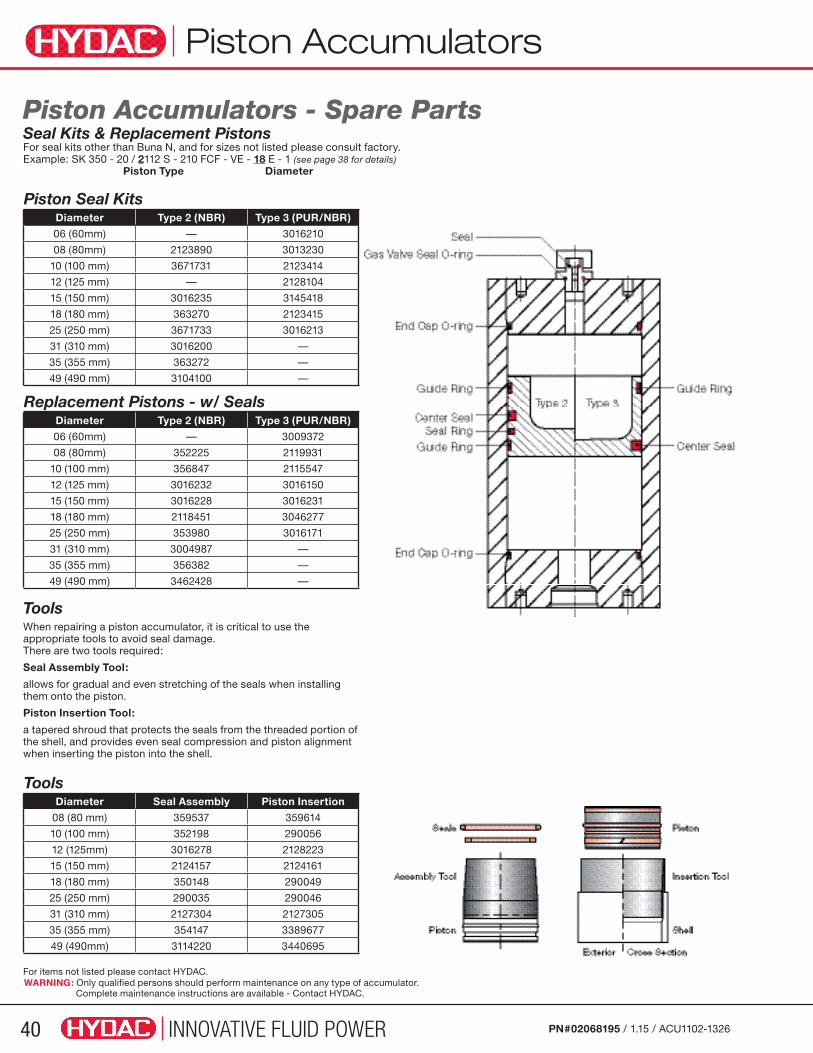
INNOVATIVE FLUID POWER40 PN#02068195 / 1.15 / ACU1102-1326
Piston Accumulators
Piston Seal KitsDiameter Type 2 (NBR) Type 3 (PUR/NBR)
06 (60mm) — 3016210
08 (80mm) 2123890 3013230
10 (100 mm) 3671731 2123414
12 (125 mm) — 2128104
15 (150 mm) 3016235 3145418
18 (180 mm) 363270 2123415
25 (250 mm) 3671733 3016213
31 (310 mm) 3016200 —
35 (355 mm) 363272 —
49 (490 mm) 3104100 —
Piston Accumulators - Spare Parts Seal Kits & Replacement Pistons For seal kits other than Buna N, and for sizes not listed please consult factory.Example: SK 350 - 20 / 2112 S - 210 FCF - VE - 18 E - 1 (see page 38 for details) Piston Type Diameter
Replacement Pistons - w/ SealsDiameter Type 2 (NBR) Type 3 (PUR/NBR)
06 (60mm) — 3009372
08 (80mm) 352225 2119931
10 (100 mm) 356847 2115547
12 (125 mm) 3016232 3016150
15 (150 mm) 3016228 3016231
18 (180 mm) 2118451 3046277
25 (250 mm) 353980 3016171
31 (310 mm) 3004987 —
35 (355 mm) 356382 —
49 (490 mm) 3462428 —
Tools When repairing a piston accumulator, it is critical to use the appropriate tools to avoid seal damage. There are two tools required:
Seal Assembly Tool:
allows for gradual and even stretching of the seals when installing them onto the piston.
Piston Insertion Tool:
a tapered shroud that protects the seals from the threaded portion of the shell, and provides even seal compression and piston alignment when inserting the piston into the shell.
ToolsDiameter Seal Assembly Piston Insertion
08 (80 mm) 359537 359614
10 (100 mm) 352198 290056
12 (125mm) 3016278 2128223
15 (150 mm) 2124157 2124161
18 (180 mm) 350148 290049
25 (250 mm) 290035 290046
31 (310 mm) 2127304 2127305
35 (355 mm) 354147 3389677
49 (490mm) 3114220 3440695
WARNING: Only qualified persons should perform maintenance on any type of accumulator. Complete maintenance instructions are available - Contact HYDAC.
For items not listed please contact HYDAC.
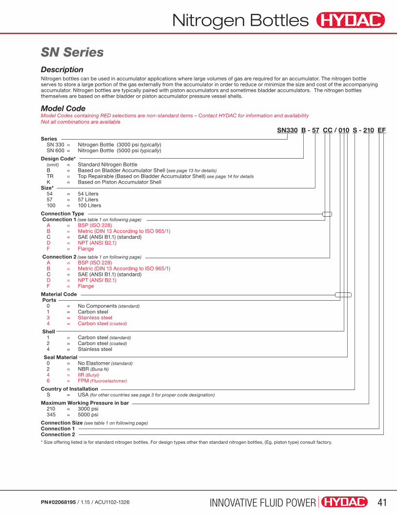
Nitrogen Bottles
INNOVATIVE FLUID POWER 41PN#02068195 / 1.15 / ACU1102-1326
Model Code Model Codes containing RED selections are non-standard items – Contact HYDAC for information and availability Not all combinations are available
SN330 B - 57 CC / 010 S - 210 EFSeries SN 330 = Nitrogen Bottle (3000 psi typically) SN 600 = Nitrogen Bottle (5000 psi typically)
Design Code* (omit) = Standard Nitrogen Bottle B = Based on Bladder Accumulator Shell (see page 13 for details) TR = Top Repairable (Based on Bladder Accumulator Shell) see page 14 for details K = Based on Piston Accumulator Shell Size* 54 = 54 Liters 57 = 57 Liters 100 = 100 Liters
Connection Type Connection 1 (see table 1 on following page) A = BSP (ISO 228) B = Metric (DIN 13 According to ISO 965/1) C = SAE (ANSI B1.1) (standard) D = NPT (ANSI B2.1) F = Flange
Connection 2 (see table 1 on following page) A = BSP (ISO 228) B = Metric (DIN 13 According to ISO 965/1) C = SAE (ANSI B1.1) (standard) D = NPT (ANSI B2.1) F = Flange
Material Code Ports 0 = No Components (standard) 1 = Carbon steel 3 = Stainless steel 4 = Carbon steel (coated)
Shell 1 = Carbon steel (standard) 2 = Carbon steel (coated) 4 = Stainless steel
Seal Material 0 = No Elastomer (standard) 2 = NBR (Buna N) 4 = IIR (Butyl) 6 = FPM (Fluoroelastomer)
Country of Installation S = USA (for other countries see page 3 for proper code designation)
Maximum Working Pressure in bar 210 = 3000 psi 345 = 5000 psi
Connection Size (see table 1 on following page) Connection 1 Connection 2 * Size offering listed is for standard nitrogen bottles. For design types other than standard nitrogen bottles, (Eg. piston type) consult factory.
SN SeriesDescriptionNitrogen bottles can be used in accumulator applications where large volumes of gas are required for an accumulator. The nitrogen bottle serves to store a large portion of the gas externally from the accumulator in order to reduce or minimize the size and cost of the accompanying accumulator. Nitrogen bottles are typically paired with piston accumulators and sometimes bladder accumulators. The nitrogen bottles themselves are based on either bladder or piston accumulator pressure vessel shells.
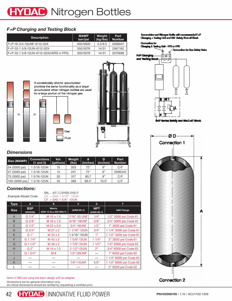
Nitrogen Bottles
INNOVATIVE FLUID POWER42 PN#02068195 / 1.15 / ACU1102-1326
Size (MAWP) Connections (1 and 2)
Vol. (gallons)
Weight (lbs)
A (inches)
D (inches)
Part Number
54 (5000 psi) 1 5/16-12UN 15 353 72” 9” C/F
57 (3000 psi) 1 5/16-12UN 15 247 72” 9” 2096345
75 (3000 psi) 1 5/16-12UN 20 317 80.7 9” C/F
100 (3000 psi) 1 5/16-12UN 25 386 89.4” 10.5” C/F
Description MAWPbar/psi
Weight (kg/lbs)
Part Number
F+P-16-3/4-16UNF-6112-02X 400/5800 4.3/9.5 2068047
F+P-32-1 5/8-12UN-6112-02X 350/5076 14/31 2067162
F+P-32-1 5/8-12UN-6112-02X(VERS 4-FPS) 350/5076 14/31 2075698
Example Model Code SN... -57CC/010S-210EF CE = SAE 1 5/16” -12UN CF = SAE 1 5/8” -12UN
Type A B C D F
Size BSP (ISO228)
Metric
(DIN 13 Acc.ISO 965/1)(ANSI B1.1)
NPT (ANSI B2.1)
SAE Flange
A G 1/4” M 12 x 1.5 7/16”-20 UNF 1/4” 1/2” 3000 psi Code 61
B G 3/8” M 18 x 1.5 9/16”-18UNF 3/8” 3/4”-3000 psi Code 61
C G 1/2” M 22 x 0.5 3/4”-16UNF 1/2” 1” 3000 psi Code 61
D G 3/4” M 27 x 2 1 1/16”-12UN 3/4” 1 1/4” 3000 psi Code 61
E G 1” M 33 x 2 1 5/16”-12UN 1” 1 1/2” 3000 psi Code 61
F G 1 1/4” M 42 x 2 1 5/8”-12UN 1 1/4” 2” 3000 psi Code 61
G G 1 1/2” M 48 x 2 1 7/8”-12UN 1 1/2” 1/2” 6000 psi Code 62
H G 2” M 14 x 1.5 2 1/2”-12UN 2” 3/4” 6000 psi Code 62
I G 1 3/4” M 8 1/2”-20UNF — 1” 6000 psi Code 62
J — — — — 1 1/4” 6000 psi Code 62
K — — 7/8”-14UNF 5/8” 1 1/2” 6000 psi Code 62
L — — — — 2” 6000 psi Code 62
Dimensions
F+P Charging and Testing Block
Connections:
Items in RED are using the basic design with an adapter.
Dimensions are for general information only, all critical dimensions should be verified by requesting a certified print.
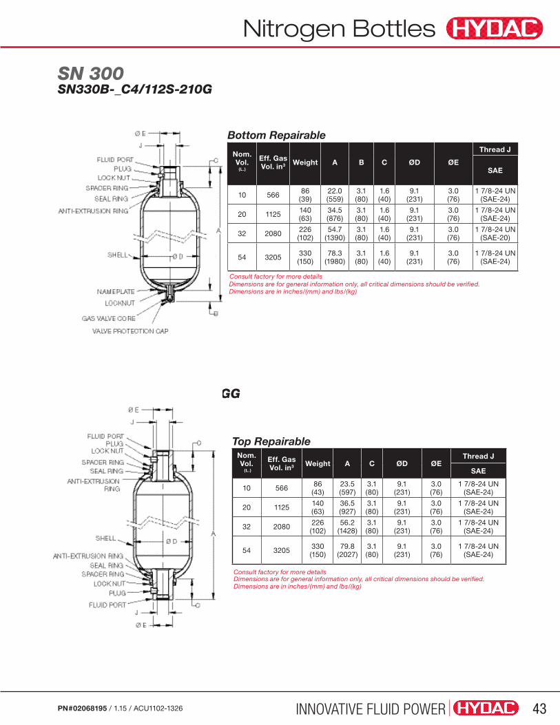
INNOVATIVE FLUID POWER 43PN#02068195 / 1.15 / ACU1102-1326
Nitrogen Bottles
Bottom Repairable
Nom. Vol.
(L.)
Eff. Gas Vol. in3 Weight A B C ØD ØE
Thread J
SAE
10 566 86(39)
22.0(559)
3.1 (80)
1.6 (40)
9.1(231)
3.0 (76)
1 7/8-24 UN(SAE-24)
20 1125 140(63)
34.5(876)
3.1 (80)
1.6 (40)
9.1(231)
3.0 (76)
1 7/8-24 UN (SAE-24)
32 2080 226(102)
54.7(1390)
3.1 (80)
1.6 (40)
9.1(231)
3.0 (76)
1 7/8-24 UN (SAE-20)
54 3205 330(150)
78.3(1980)
3.1(80)
1.6(40)
9.1(231)
3.0(76)
1 7/8-24 UN (SAE-24)
Consult factory for more details
Top RepairableNom. Vol. (L.)
Eff. Gas Vol. in3 Weight A C ØD ØE
Thread J
SAE
10 566 86(43)
23.5(597)
3.1 (80)
9.1(231)
3.0 (76)
1 7/8-24 UN(SAE-24)
20 1125 140(63)
36.5(927)
3.1 (80)
9.1(231)
3.0 (76)
1 7/8-24 UN (SAE-24)
32 2080 226(102)
56.2(1428)
3.1 (80)
9.1(231)
3.0 (76)
1 7/8-24 UN (SAE-24)
54 3205 330(150)
79.8(2027)
3.1(80)
9.1(231)
3.0(76)
1 7/8-24 UN (SAE-24)
SN 300SN330B-_C4/112S-210G
SN330BTR-_CC/112S-210GG
Consult factory for more details
Dimensions are for general information only, all critical dimensions should be verified.Dimensions are in inches/(mm) and lbs/(kg)
Dimensions are for general information only, all critical dimensions should be verified.Dimensions are in inches/(mm) and lbs/(kg)

INNOVATIVE FLUID POWER44 PN#02068195 / 1.15 / ACU1102-1326
DescriptionThe pressure fluctuations occurring in hydraulic systems can be periodic or single occurrence problems due to:
• Flow rate fluctuations from displacement pumps
• Actuation of shut-off and control valves with short opening and closing times
• Switching pumps on and off
• Sudden linking of hydraulic circuits with different pressure levels
Dampeners have two fluid connections for inline mounting. The volume of flow is directed straight at the bladder or diaphragm by diverting it into the fluid valve. This causes direct contact of the fluid flow with the bladder or diaphragm which balances the flow rate fluctuations via the gas volume. It is particularly effective with higher frequency oscillations. The gas precharge pressure is adjusted for the specific systems operating conditions.
ConstructionHYDAC pulsation dampeners consist of:
• The welded or forged pressure vessel in carbon steel; for chemically aggressive fluids they are available in coated carbon steel or stainless steel
• The special fluid valve with inline connection, which guides the flow into the vessels (threaded or flange connections available)
• The bladder or diaphragm in various compounds as listed below
Compound MaterialsNot all fluids are compatible with every elastomer at all temperatures. Therefore, HYDAC offers the following choice of elastomers:
• NBR (Standard Nitrile)
• LT-NBR (Low Temperature Nitrile)
• ECO (Epichlorohydrin)
• IIR (Butyl)
• FPM (Fluoroelastomer)
• others (available upon request)
To determine which material is appropriate...
ALWAYS REFER TO FLUID MANUFACTURER’S RECOMMENDATION
Corrosion ProtectionFor use with certain aggressive or corrosive fluids, or in a corrosive environment, HYDAC offers protective coatings and corrosive resistant materials (i.e. stainless steel) for the accumulator parts that come in contact with the fluid, or are exposed to the hostile environment.
Mounting PositionThe mounting position of hydraulic dampeners is dependent on the dampener chosen and the specific application. The preferred position is typically vertical.
System MountingDampeners should be mounted as close as possible to the pulsation source.
ApplicationsPulsation dampeners are used to:
• Reduce vibrations caused by pipes, valves, couplings, etc. in order to prevent pipe and valve damage
• Protect measurement instruments and eliminate the impaired performance caused by pulsations
• Reduce system noise
• Increase machine performance
• Allow the connection of multiple pumps to one line
• Increase the allowable rpm and feed pressure of pumps
• Reduce system breakdowns and increase the service life of the system
Pulsation Dampeners
SB…P and SBO…P SeriesPulsation Dampeners
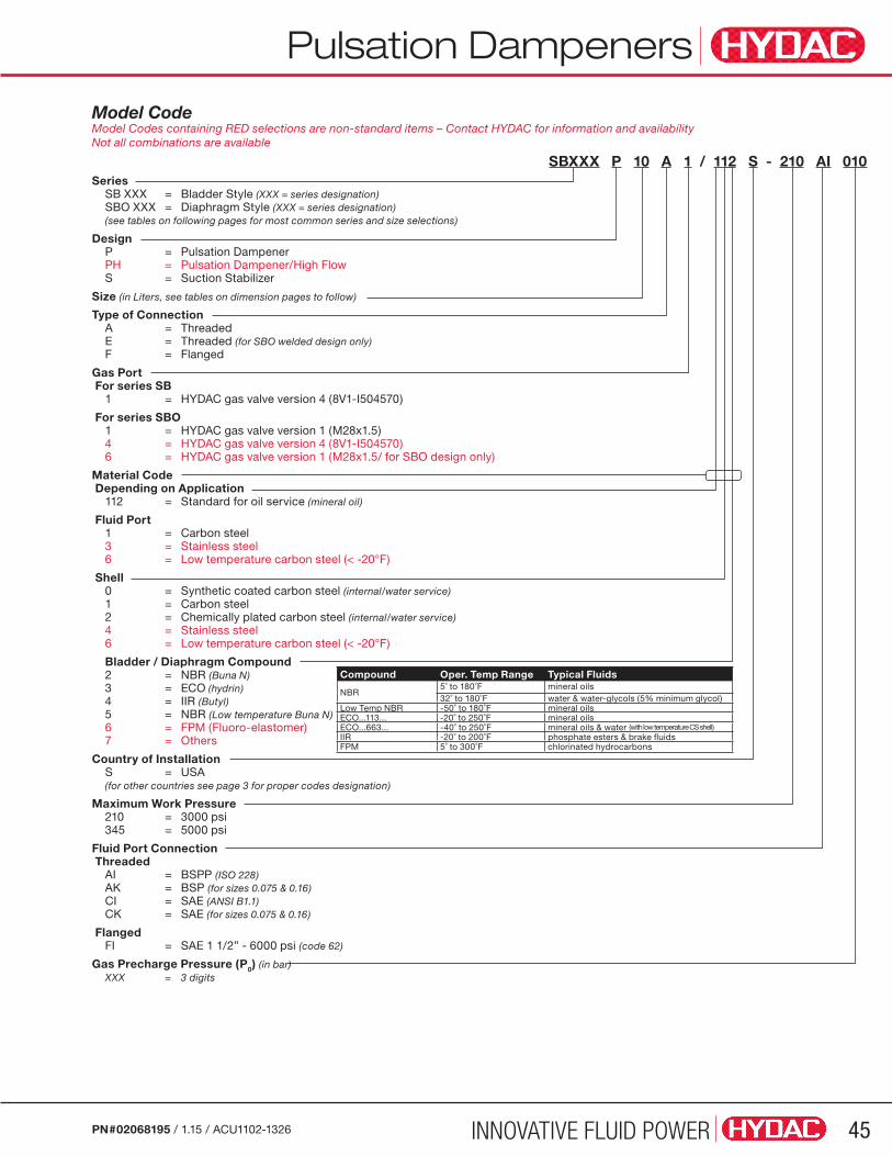
INNOVATIVE FLUID POWER 45PN#02068195 / 1.15 / ACU1102-1326
Model Code Model Codes containing RED selections are non-standard items – Contact HYDAC for information and availability Not all combinations are available
SBXXX P 10 A 1 / 112 S - 210 AI 010Series SB XXX = Bladder Style (XXX = series designation) SBO XXX = Diaphragm Style (XXX = series designation) (see tables on following pages for most common series and size selections)
Design P = Pulsation Dampener PH = Pulsation Dampener/High Flow S = Suction Stabilizer
Size (in Liters, see tables on dimension pages to follow)
Type of Connection A = Threaded E = Threaded (for SBO welded design only) F = Flanged
Gas Port For series SB 1 = HYDAC gas valve version 4 (8V1-I504570)
For series SBO 1 = HYDAC gas valve version 1 (M28x1.5) 4 = HYDAC gas valve version 4 (8V1-I504570) 6 = HYDAC gas valve version 1 (M28x1.5/ for SBO design only)
Material Code Depending on Application 112 = Standard for oil service (mineral oil)
Fluid Port 1 = Carbon steel 3 = Stainless steel 6 = Low temperature carbon steel (< -20°F)
Shell 0 = Synthetic coated carbon steel (internal/water service) 1 = Carbon steel 2 = Chemically plated carbon steel (internal/water service) 4 = Stainless steel 6 = Low temperature carbon steel (< -20°F)
Bladder / Diaphragm Compound 2 = NBR (Buna N) 3 = ECO (hydrin) 4 = IIR (Butyl) 5 = NBR (Low temperature Buna N) 6 = FPM (Fluoro-elastomer) 7 = Others
Country of Installation S = USA (for other countries see page 3 for proper codes designation)
Maximum Work Pressure 210 = 3000 psi 345 = 5000 psi
Fluid Port Connection Threaded AI = BSPP (ISO 228) AK = BSP (for sizes 0.075 & 0.16) CI = SAE (ANSI B1.1) CK = SAE (for sizes 0.075 & 0.16)
Flanged FI = SAE 1 1/2” - 6000 psi (code 62)
Gas Precharge Pressure (P0) (in bar) XXX = 3 digits
Pulsation Dampeners
Compound Oper. Temp Range Typical Fluids
NBR5˚ to 180˚F mineral oils32˚ to 180˚F water & water-glycols (5% minimum glycol)
Low Temp NBR -50˚ to 180˚F mineral oilsECO...113... -20˚ to 250˚F mineral oilsECO...663... -40˚ to 250˚F mineral oils & water (with low temperature CS shell)IIR -20˚ to 200˚F phosphate esters & brake fluidsFPM 5˚ to 300˚F chlorinated hydrocarbons
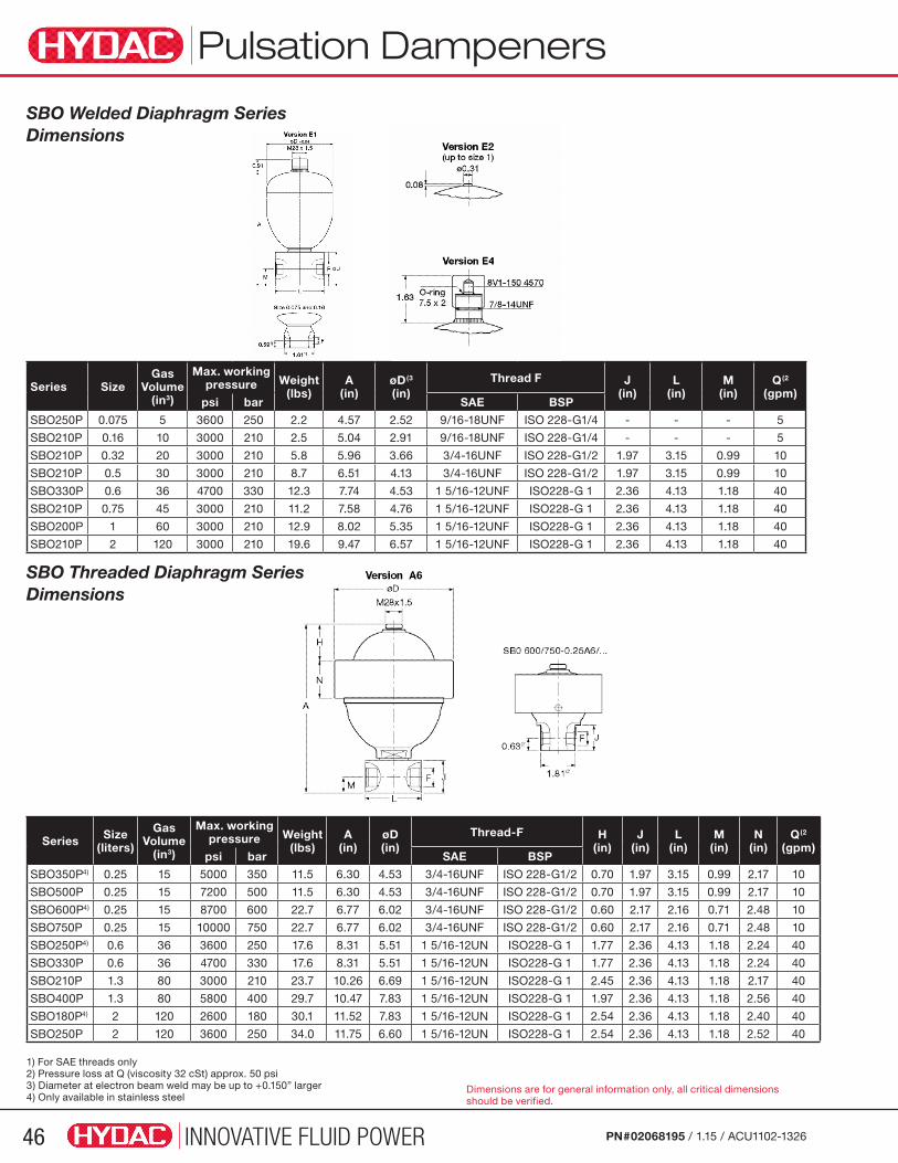
INNOVATIVE FLUID POWER46 PN#02068195 / 1.15 / ACU1102-1326
SBO Welded Diaphragm Series Dimensions
Series SizeGas
Volume (in3)
Max. working pressure Weight
(lbs)A
(in)øD(3 (in)
Thread F J (in)
L (in)
M (in)
Q(2 (gpm)
psi bar SAE BSP
SBO250P 0.075 5 3600 250 2.2 4.57 2.52 9/16-18UNF ISO 228-G1/4 - - - 5
SBO210P 0.16 10 3000 210 2.5 5.04 2.91 9/16-18UNF ISO 228-G1/4 - - - 5
SBO210P 0.32 20 3000 210 5.8 5.96 3.66 3/4-16UNF ISO 228-G1/2 1.97 3.15 0.99 10
SBO210P 0.5 30 3000 210 8.7 6.51 4.13 3/4-16UNF ISO 228-G1/2 1.97 3.15 0.99 10
SBO330P 0.6 36 4700 330 12.3 7.74 4.53 1 5/16-12UNF ISO228-G 1 2.36 4.13 1.18 40
SBO210P 0.75 45 3000 210 11.2 7.58 4.76 1 5/16-12UNF ISO228-G 1 2.36 4.13 1.18 40
SBO200P 1 60 3000 210 12.9 8.02 5.35 1 5/16-12UNF ISO228-G 1 2.36 4.13 1.18 40
SBO210P 2 120 3000 210 19.6 9.47 6.57 1 5/16-12UNF ISO228-G 1 2.36 4.13 1.18 40
SBO Threaded Diaphragm Series Dimensions
Series Size(liters)
Gas Volume
(in3)
Max. working pressure Weight
(lbs)A
(in)øD (in)
Thread-F H (in)
J (in)
L (in)
M (in)
N (in)
Q(2 (gpm)
psi bar SAE BSP
SBO350P4) 0.25 15 5000 350 11.5 6.30 4.53 3/4-16UNF ISO 228-G1/2 0.70 1.97 3.15 0.99 2.17 10
SBO500P 0.25 15 7200 500 11.5 6.30 4.53 3/4-16UNF ISO 228-G1/2 0.70 1.97 3.15 0.99 2.17 10
SBO600P4) 0.25 15 8700 600 22.7 6.77 6.02 3/4-16UNF ISO 228-G1/2 0.60 2.17 2.16 0.71 2.48 10
SBO750P 0.25 15 10000 750 22.7 6.77 6.02 3/4-16UNF ISO 228-G1/2 0.60 2.17 2.16 0.71 2.48 10
SBO250P4) 0.6 36 3600 250 17.6 8.31 5.51 1 5/16-12UN ISO228-G 1 1.77 2.36 4.13 1.18 2.24 40
SBO330P 0.6 36 4700 330 17.6 8.31 5.51 1 5/16-12UN ISO228-G 1 1.77 2.36 4.13 1.18 2.24 40
SBO210P 1.3 80 3000 210 23.7 10.26 6.69 1 5/16-12UN ISO228-G 1 2.45 2.36 4.13 1.18 2.17 40
SBO400P 1.3 80 5800 400 29.7 10.47 7.83 1 5/16-12UN ISO228-G 1 1.97 2.36 4.13 1.18 2.56 40
SBO180P4) 2 120 2600 180 30.1 11.52 7.83 1 5/16-12UN ISO228-G 1 2.54 2.36 4.13 1.18 2.40 40
SBO250P 2 120 3600 250 34.0 11.75 6.60 1 5/16-12UN ISO228-G 1 2.54 2.36 4.13 1.18 2.52 40
1) For SAE threads only2) Pressure loss at Q (viscosity 32 cSt) approx. 50 psi3) Diameter at electron beam weld may be up to +0.150” larger4) Only available in stainless steel
Pulsation Dampeners
Dimensions are for general information only, all critical dimensions should be verified.
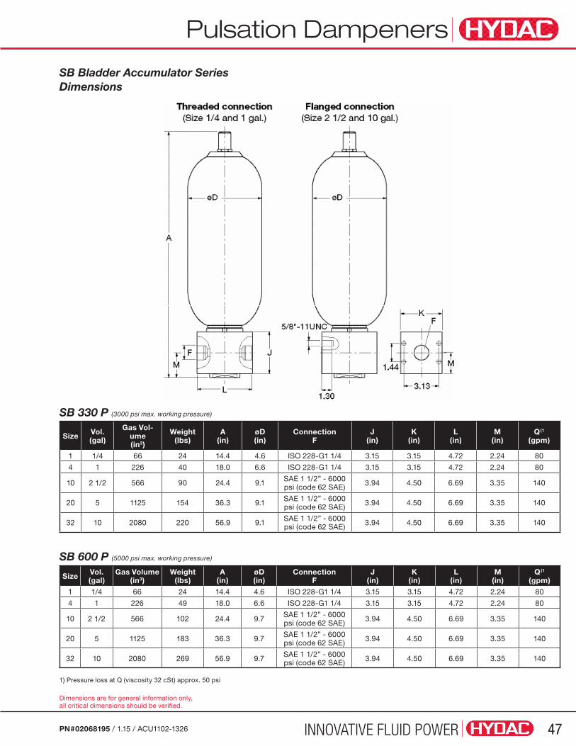
INNOVATIVE FLUID POWER 47PN#02068195 / 1.15 / ACU1102-1326
SB Bladder Accumulator Series Dimensions
Size Vol.(gal)
Gas Vol-ume(in3)
Weight(lbs)
A(in)
øD(in)
ConnectionF
J(in)
K(in)
L(in)
M(in)
Q(1
(gpm)
1 1/4 66 24 14.4 4.6 ISO 228-G1 1/4 3.15 3.15 4.72 2.24 80
4 1 226 40 18.0 6.6 ISO 228-G1 1/4 3.15 3.15 4.72 2.24 80
10 2 1/2 566 90 24.4 9.1 SAE 1 1/2” - 6000 psi (code 62 SAE) 3.94 4.50 6.69 3.35 140
20 5 1125 154 36.3 9.1 SAE 1 1/2” - 6000 psi (code 62 SAE) 3.94 4.50 6.69 3.35 140
32 10 2080 220 56.9 9.1 SAE 1 1/2” - 6000 psi (code 62 SAE) 3.94 4.50 6.69 3.35 140
SB 600 P (5000 psi max. working pressure)
Size Vol.(gal)
Gas Volume(in3)
Weight(lbs)
A(in)
øD(in)
ConnectionF
J(in)
K(in)
L(in)
M(in)
Q(1
(gpm)
1 1/4 66 24 14.4 4.6 ISO 228-G1 1/4 3.15 3.15 4.72 2.24 80
4 1 226 49 18.0 6.6 ISO 228-G1 1/4 3.15 3.15 4.72 2.24 80
10 2 1/2 566 102 24.4 9.7 SAE 1 1/2” - 6000 psi (code 62 SAE) 3.94 4.50 6.69 3.35 140
20 5 1125 183 36.3 9.7 SAE 1 1/2” - 6000 psi (code 62 SAE) 3.94 4.50 6.69 3.35 140
32 10 2080 269 56.9 9.7 SAE 1 1/2” - 6000 psi (code 62 SAE) 3.94 4.50 6.69 3.35 140
Pulsation Dampeners
1) Pressure loss at Q (viscosity 32 cSt) approx. 50 psi
SB 330 P (3000 psi max. working pressure)
Dimensions are for general information only, all critical dimensions should be verified.

INNOVATIVE FLUID POWER48 PN#02068195 / 1.15 / ACU1102-1326
DescriptionIn addition to Bladder, Piston and Diaphragm accumulators, HYDAC can now offer a fourth series – Metal Bellows Accumulators.
A metal separating element is used between the fluid and gas side of the metal bellows accumulator. This makes it virtually gas tight, eliminating elastomer separating elements and seals from the accumulator and providing a solution for some very challenging accumulator pulsation application conditions.
• Heavy Diesel Engines-Mobile, Marine & Industrial: Fuel injection systems in heavy diesel engines generate significant cyclic pressure fluctuations or pulsations. The Metal Bellows Accumulator can be used as a pulsation dampener on both the supply and return lines close to the engine which generates the pulsations. The metal bellows element provides a more robust method of separating the nitrogen gas from the diesel fuel and also manages the next two related problems.
• Elastomer Resistance to Fuels & High Temperature: Alternatives to diesel fuels, such as bio-oils or heavy fuel oil require higher fuel injection temperatures up to 320°F. Even FKM (Viton®) will have compatibility problems and shortened service life with fluids of this type under these extreme conditions. Metal Bellows Accumulators eliminate this elastomer compatibility issue.
• Nitrogen Gas Loss Through the Elastomer - Permeation: The high fuel fluid temperatures compound and nitrogen gas permeation through the elastomers creating higher gas losses and increase the need for gas monitoring and gas precharge maintenance. If nitrogen gas losses become excessive, a bladder or diaphragm will experience damage and possible failure in operation.
The recently developed solution from HYDAC is the Metal Bellows Accumulator. Instead of a bladder or diaphragm, a metal bellows is used as the flexible separating element between fluid and gas. The metal bellows is resistant to all conventional fuels over a very wide temperature range. Heavy fuel oil at temperatures from -85 °F to 320 °F is is easily handled these dampers. The metal bellows is welded to the other components and is therefore completely gas tight. It is able to expand and contract inside the accumulator without any friction or abrasion and it can operate for a very long period of time (years) with a single adjustment. Monitoring and maintenance for this type of damper is therefore reduced to a minimum.
ConstructionMetal Bellows Accumulators are available in two different styles:
• SM50P – Flange connection with fluid diverter design and
• SM50 – Threaded connection w/o fluid diverter, good for applications requiring a retrofit of competitors accumulators.
A diverting block is built into the fuel side of the damper which forces the fuel directly into the accumulator, thereby increasing the damping efficiency considerably. If two dampers are fitted to the fuel system (in both supply and return line), no pressure fluctuations can leave the engine before passing through one of the metal bellows dampers.
If a conventional accumulator can no longer perform its function, this can lead to expensive maintenance and repair work. We can offer a retrofit alternative - Replacement without the need for modification.
Features There are two different design types of metal bellows; convoluted (formed) and diaphragm (welded). Each has a slightly different design and performance advantages also vary.
Convoluted bellows (formed)
• Heavy Diesel Engines
• Very good dampening features
• Resistant to contamination
Diaphragm bellows (welded)• Very suitable for high pressures
• Very good energy storage features
• High displacement volume
• Compact
Areas of Application• Pulsation dampening
• Volume compensation
Industry Sectors• Heavy diesel engines (e.g. power plants and ships)
• Process technology
• Wind energy
Metal Bellows
SM50 & SM50PMetal Bellows

INNOVATIVE FLUID POWER 49PN#02068195 / 1.15 / ACU1102-1326
Model Code Model Codes containing RED selections are non-standard items – Contact HYDAC for information and availability Not all combinations are available
SM50 P 0.5 W E 1/ 116 U - 50 AAJ 2.5Series
Design = accumulator without diverting block* L = light-weight accumulator P = damper with diverter block
Size SM50 = 0.5 to 1.6L SM50P = 0.5 to 3.8L
Verison W = convoluted bellows M = diaphragm bellows*
Type of Shell A = screw type E = weld type* G = formed type*
Gas Connection 1 = gas pressure adjustable (M28 x 1.5) 2 = gas pressur pre-set, non-adjustable gas locking screw* 3 = gas pressure adjustable (M16x 1.5)
Material Code
Fluid Connection 1 = carbon steel 2 = carbon steel with corrosion protection 3 = stainless steel
Shell 1 = carbon steel 2 = carbon steel with corrosion protection 4 = stainless steel
Seal Compound 0 = no seal 2 = NBR* 5 = low temperature NBR* 6 = FKM
Country of Installation U = PED (For other countries see page 3 for proper code designation)
Maximum Working Pressure (in bar)
Fluid Port Connection
Pre-charge pressure (in bar)
Metal Bellows

INNOVATIVE FLUID POWER50 PN#02068195 / 1.15 / ACU1102-1326
Metal Bellows
Metal Bellows SM50 & SM50P Technical Information
Technical specifications HYDAC Metal Bellows Accumulators Flange Connection Design Threaded Connection Design
Series SM50P SM50
Max. design pressure 725 psi 725 psi
Max. working pressure * 43.5 psi - 174 psi 43.5 psi - 174 psi
Max. pre-charge pressure at Tmax 58 psi 116 psi
Design Temperature range 14 F˚ - 320 F˚
Operating media Diesel and heavy fuel oil, boifuels
Size 0.5 - 3.8 L 0.5 - 1.6L
Effective gas volume ≈0.5 L (nitrogen)
Gas side pre-charge fluid 0.6 L (ethylene glycol) 0.3 L (ethylene glycol)
Fluctuating volume * max 0.04 L
Material Carbon steel (primed externally)
Design and Approval * e.g.: PED, ABS, DNV, LR, BV, GL, RMRS
Fluid connection *Diverting block SAE 1 1/4”Diverting block SAE 2”Diverting block SAE 3”
2” BSP (female)or with adapter
alson for 1 1/2” BSP (male)
Gas connection M28x 1.5 for Universal Charging and Testing Unit - FPU-1
Mounting position * vertical (gas connection at top) preferably vertical (gas connection at top)
Weight 48.5 - 73lbs 20lbs
*Others on request
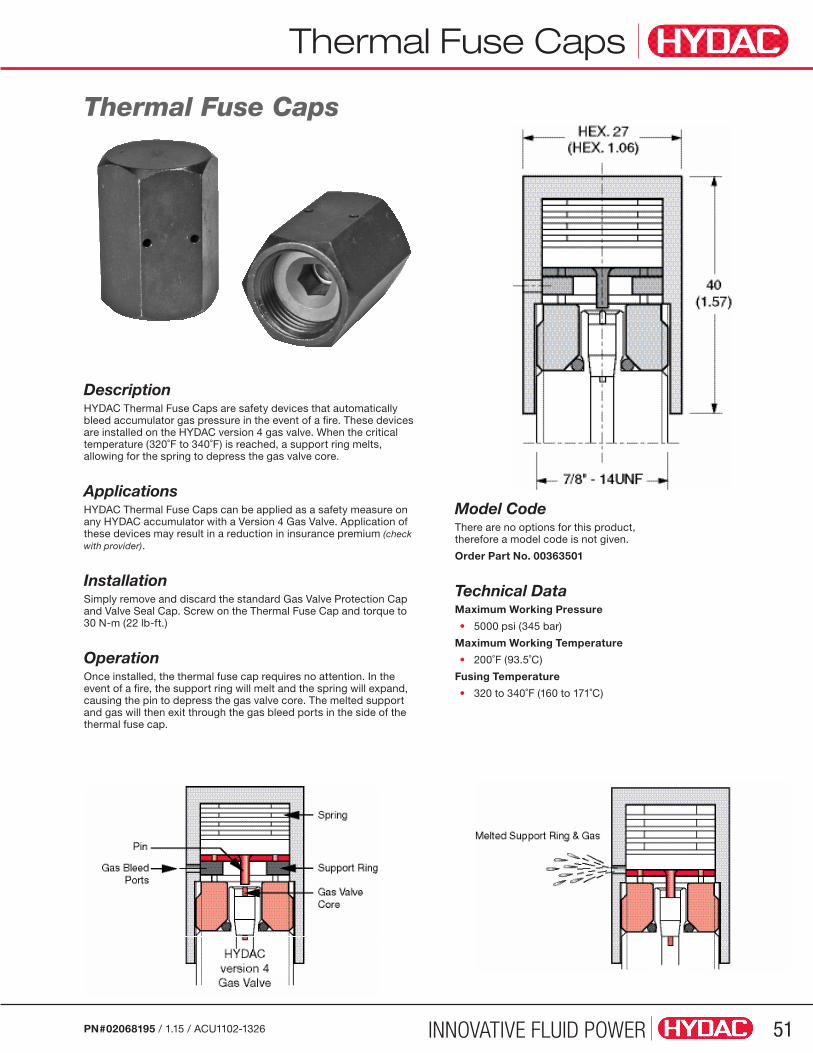
INNOVATIVE FLUID POWER 51PN#02068195 / 1.15 / ACU1102-1326
Thermal Fuse Caps
DescriptionHYDAC Thermal Fuse Caps are safety devices that automatically bleed accumulator gas pressure in the event of a fire. These devices are installed on the HYDAC version 4 gas valve. When the critical temperature (320˚F to 340˚F) is reached, a support ring melts, allowing for the spring to depress the gas valve core.
ApplicationsHYDAC Thermal Fuse Caps can be applied as a safety measure on any HYDAC accumulator with a Version 4 Gas Valve. Application of these devices may result in a reduction in insurance premium (check with provider).
InstallationSimply remove and discard the standard Gas Valve Protection Cap and Valve Seal Cap. Screw on the Thermal Fuse Cap and torque to 30 N-m (22 lb-ft.)
OperationOnce installed, the thermal fuse cap requires no attention. In the event of a fire, the support ring will melt and the spring will expand, causing the pin to depress the gas valve core. The melted support and gas will then exit through the gas bleed ports in the side of the thermal fuse cap.
Model CodeThere are no options for this product, therefore a model code is not given.
Order Part No. 00363501
Technical DataMaximum Working Pressure
• 5000 psi (345 bar)
Maximum Working Temperature
• 200˚F (93.5˚C)
Fusing Temperature
• 320 to 340˚F (160 to 171˚C)
Thermal Fuse Caps
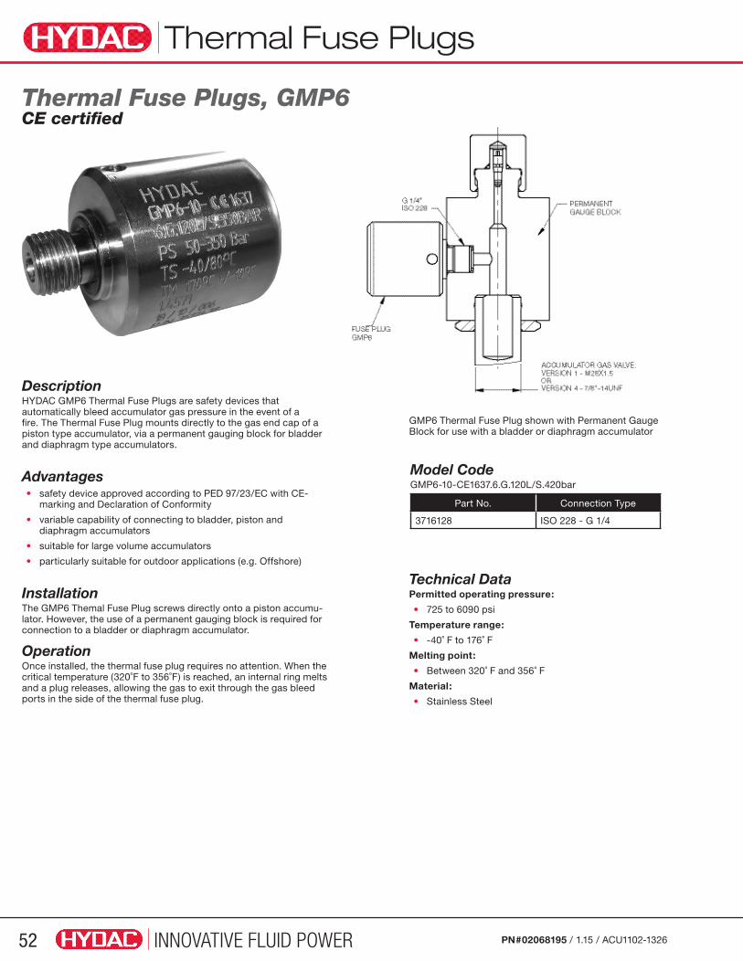
INNOVATIVE FLUID POWER52 PN#02068195 / 1.15 / ACU1102-1326
Thermal Fuse Plugs
Description HYDAC GMP6 Thermal Fuse Plugs are safety devices that automatically bleed accumulator gas pressure in the event of a fire. The Thermal Fuse Plug mounts directly to the gas end cap of a piston type accumulator, via a permanent gauging block for bladder and diaphragm type accumulators.
Advantages• safety device approved according to PED 97/23/EC with CE- marking and Declaration of Conformity
• variable capability of connecting to bladder, piston and diaphragm accumulators
• suitable for large volume accumulators
• particularly suitable for outdoor applications (e.g. Offshore)
Installation The GMP6 Themal Fuse Plug screws directly onto a piston accumu-lator. However, the use of a permanent gauging block is required for connection to a bladder or diaphragm accumulator.
Operation Once installed, the thermal fuse plug requires no attention. When the critical temperature (320˚F to 356˚F) is reached, an internal ring melts and a plug releases, allowing the gas to exit through the gas bleed ports in the side of the thermal fuse plug.
Thermal Fuse Plugs, GMP6CE certified
Model Code GMP6-10-CE1637.6.G.120L/S.420bar
Part No. Connection Type
3716128 ISO 228 - G 1/4
GMP6 Thermal Fuse Plug shown with Permanent Gauge Block for use with a bladder or diaphragm accumulator
Technical Data Permitted operating pressure:
• 725 to 6090 psi
Temperature range:
• -40˚ F to 176˚ F
Melting point:
• Between 320˚ F and 356˚ F
Material:
• Stainless Steel

INNOVATIVE FLUID POWER 53PN#02068195 / 1.15 / ACU1102-1326
Safety & Shut-off Blocks
Note: When using hydro-pneumatic accumulators for stored hazardous energy, HYDAC recommends the use of its Safety and Shut-off Block (SAF) with solenoid operated bleed valve.
Technical Specifications Fluids Mineral oil, hydraulic oil, water glycol, non-flammable fluids (other fluids upon request)
Temperature (for carbon steel) 5º to 180ºF (-15º to 80ºC)
Maximum Working Pressure up to 5800 psi (400 bar)
SAF SeriesSafety & Shut-off Blocks
ConstructionThe Safety and Shut-off Block consists of a valve block, a built-in pressure relief valve, a main shut-off valve, and a manually operated bleed valve. In addition, an optional solenoid operated bleed valve allows automatic pressure relief of the accumulator or user unit and therefore relief of the hydraulic system in an emergency or during shut-down. The necessary return line connection is provided in addition to the gauge connection.
Standard ModelsModel with manually operated bleed valve
The basic model type “M” contains a manually operated bleed valve for manual pressure release of the accumulator.
DescriptionHYDAC safety and shut-off blocks are designed to protect, shut-off, and discharge hydraulic accumulators or user units. The compact design simplifies the hydraulic system connection and offers the following advantages:
• minimum space compared to individual components
• reduced installation time
• various system connections
• system lockout
Safety & Shut-off Block Features 1 – pressure relief valve (DB12)
2 – pressure gauge (optional)
3 – main shut-off valve
4 – manual bleed valve
5 – 2-way solenoid operated bleed valve (optional)
6 – accumulator
Circuit Diagram Connections S – Accumulator Connection
P – System Connection
T – Tank Connection
M1 – Gauge Connection
Pressure Relief Valve (DB12) This valve cannot be set to values in the shaded area
Model with solenoid operated bleed valve
In addition to the features of the type “M” block, the type “E” model also contains a solenoid operated bleed valve for automatic pressure release of the accumulator.
Sizes: SAF 10 E SAF 20 E SAF 32 E
Sizes: SAF 10 M SAF 20 M SAF 32 M
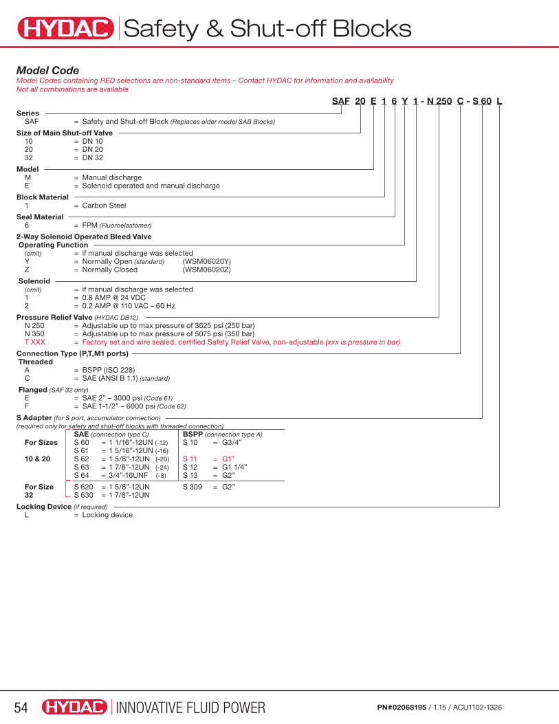
INNOVATIVE FLUID POWER54 PN#02068195 / 1.15 / ACU1102-1326
Safety & Shut-off Blocks
Model Code Model Codes containing RED selections are non-standard items – Contact HYDAC for information and availability Not all combinations are available
SAF 20 E 1 6 Y 1 - N 250 C - S 60 LSeries SAF = Safety and Shut-off Block (Replaces older model SAB Blocks)
Size of Main Shut-off Valve 10 = DN 10 20 = DN 20 32 = DN 32
Model M = Manual discharge E = Solenoid operated and manual discharge
Block Material 1 = Carbon Steel
Seal Material 6 = FPM (Fluoroelastomer)
2-Way Solenoid Operated Bleed Valve Operating Function (omit) = if manual discharge was selected Y = Normally Open (standard) (WSM06020Y) Z = Normally Closed (WSM06020Z)
Solenoid (omit) = if manual discharge was selected 1 = 0.8 AMP @ 24 VDC 2 = 0.2 AMP @ 110 VAC – 60 Hz
Pressure Relief Valve (HYDAC DB12) N 250 = Adjustable up to max pressure of 3625 psi (250 bar) N 350 = Adjustable up to max pressure of 5075 psi (350 bar) T XXX = Factory set and wire sealed, certified Safety Relief Valve, non-adjustable (xxx is pressure in bar)
Connection Type (P,T,M1 ports) Threaded A = BSPP (ISO 228) C = SAE (ANSI B 1.1) (standard)
Flanged (SAF 32 only) E = SAE 2” – 3000 psi (Code 61) F = SAE 1-1/2” – 6000 psi (Code 62)
S Adapter (for S port, accumulator connection) (required only for safety and shut-off blocks with threaded connection) SAE (connection type C) BSPP (connection type A) For Sizes S 60 = 1 1/16”-12UN (-12) S 10 = G3/4” S 61 = 1 5/16”-12UN (-16) 10 & 20 S 62 = 1 5/8”-12UN (-20) S 11 = G1” S 63 = 1 7/8”-12UN (-24) S 12 = G1 1/4” S 64 = 3/4”-16UNF (-8) S 13 = G2”
For Size S 620 = 1 5/8”-12UN S 309 = G2” 32 S 630 = 1 7/8”-12UN
Locking Device (if required) L = Locking device
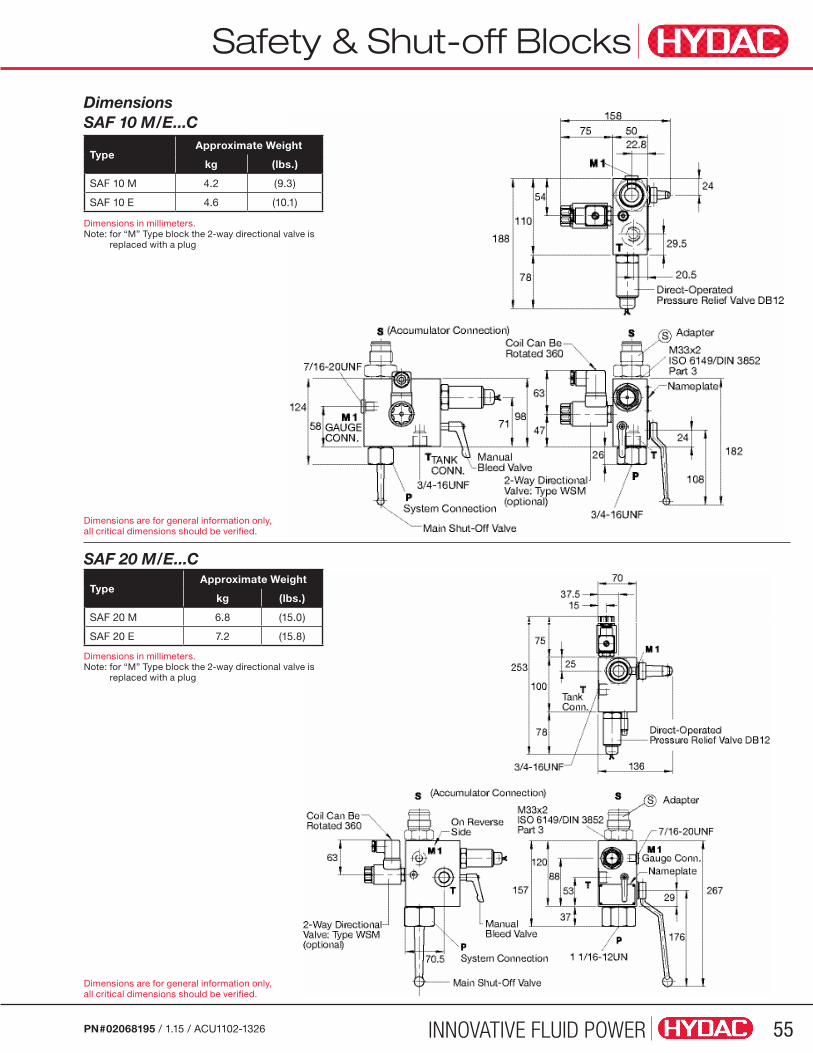
INNOVATIVE FLUID POWER 55PN#02068195 / 1.15 / ACU1102-1326
Safety & Shut-off Blocks
Dimensions SAF 10 M/E...C
SAF 20 M/E...C
TypeApproximate Weight
kg (lbs.)
SAF 20 M 6.8 (15.0)
SAF 20 E 7.2 (15.8)
TypeApproximate Weight
kg (lbs.)
SAF 10 M 4.2 (9.3)
SAF 10 E 4.6 (10.1)
Dimensions in millimeters. Note: for “M” Type block the 2-way directional valve is
replaced with a plug
Dimensions in millimeters.Note: for “M” Type block the 2-way directional valve is
replaced with a plug
Dimensions are for general information only, all critical dimensions should be verified.
Dimensions are for general information only, all critical dimensions should be verified.
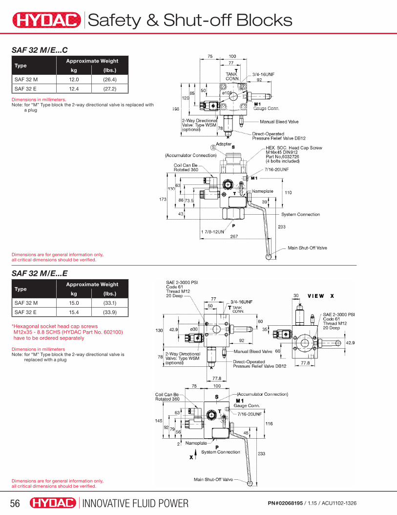
INNOVATIVE FLUID POWER56 PN#02068195 / 1.15 / ACU1102-1326
SAF 32 M/E...E
* Hexagonal socket head cap screws M12x35 - 8.8 SCHS (HYDAC Part No. 602100) have to be ordered separately
Dimensions in millimetersNote: for “M” Type block the 2-way directional valve is
replaced with a plug
SAF 32 M/E...C
TypeApproximate Weight
kg (lbs.)
SAF 32 M 15.0 (33.1)
SAF 32 E 15.4 (33.9)
Dimensions in millimeters.Note: for “M” Type block the 2-way directional valve is replaced with
a plug
TypeApproximate Weight
kg (lbs.)
SAF 32 M 12.0 (26.4)
SAF 32 E 12.4 (27.2)
Dimensions are for general information only, all critical dimensions should be verified.
Dimensions are for general information only, all critical dimensions should be verified.
Safety & Shut-off Blocks
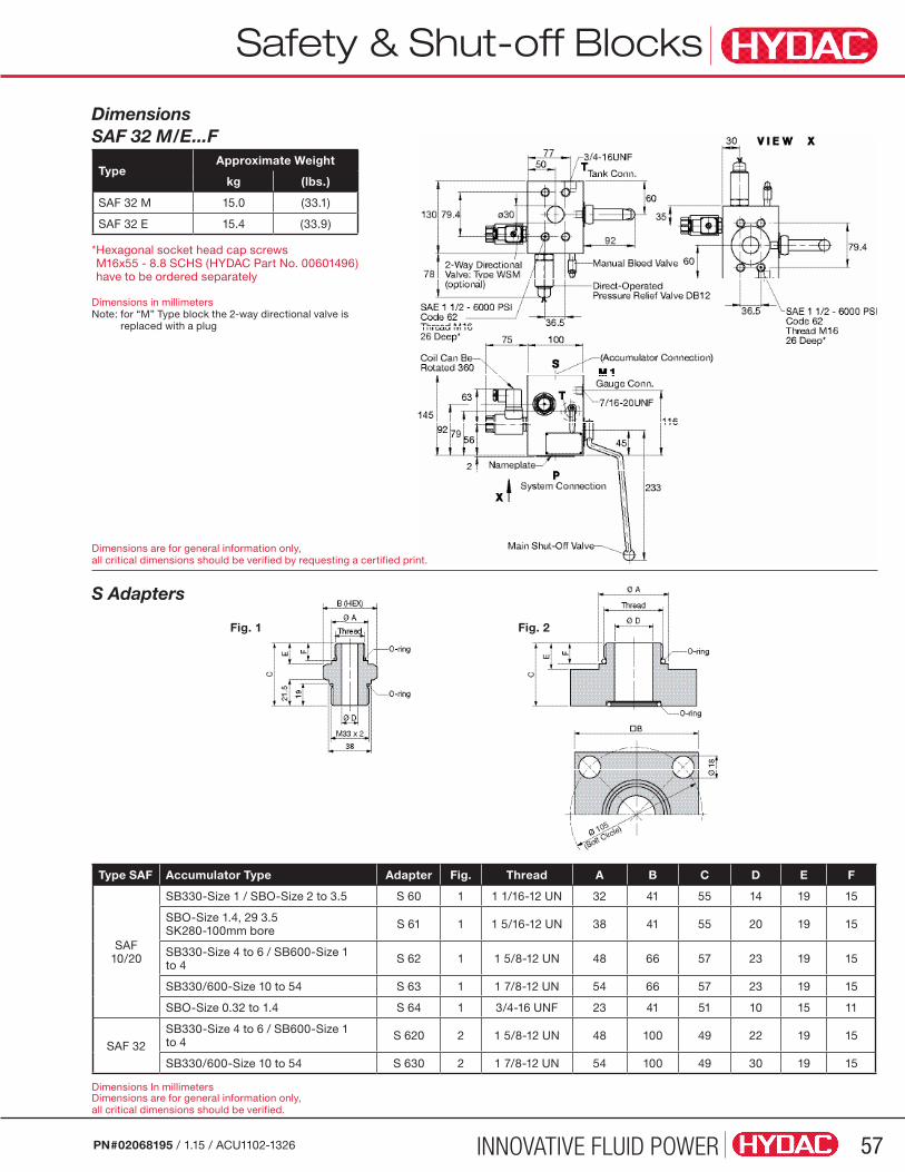
INNOVATIVE FLUID POWER 57PN#02068195 / 1.15 / ACU1102-1326
Safety & Shut-off Blocks
Dimensions are for general information only, all critical dimensions should be verified.
Dimensions In millimeters
Dimensions SAF 32 M/E...F
* Hexagonal socket head cap screws M16x55 - 8.8 SCHS (HYDAC Part No. 00601496) have to be ordered separately
Dimensions in millimetersNote: for “M” Type block the 2-way directional valve is
replaced with a plug
TypeApproximate Weight
kg (lbs.)
SAF 32 M 15.0 (33.1)
SAF 32 E 15.4 (33.9)
S Adapters
Type SAF Accumulator Type Adapter Fig. Thread A B C D E F
SAF10/20
SB330-Size 1 / SBO-Size 2 to 3.5 S 60 1 1 1/16-12 UN 32 41 55 14 19 15
SBO-Size 1.4, 29 3.5 SK280-100mm bore S 61 1 1 5/16-12 UN 38 41 55 20 19 15
SB330-Size 4 to 6 / SB600-Size 1 to 4 S 62 1 1 5/8-12 UN 48 66 57 23 19 15
SB330/600-Size 10 to 54 S 63 1 1 7/8-12 UN 54 66 57 23 19 15
SBO-Size 0.32 to 1.4 S 64 1 3/4-16 UNF 23 41 51 10 15 11
SAF 32
SB330-Size 4 to 6 / SB600-Size 1 to 4 S 620 2 1 5/8-12 UN 48 100 49 22 19 15
SB330/600-Size 10 to 54 S 630 2 1 7/8-12 UN 54 100 49 30 19 15
Dimensions are for general information only, all critical dimensions should be verified by requesting a certified print.
Fig. 1 Fig. 2
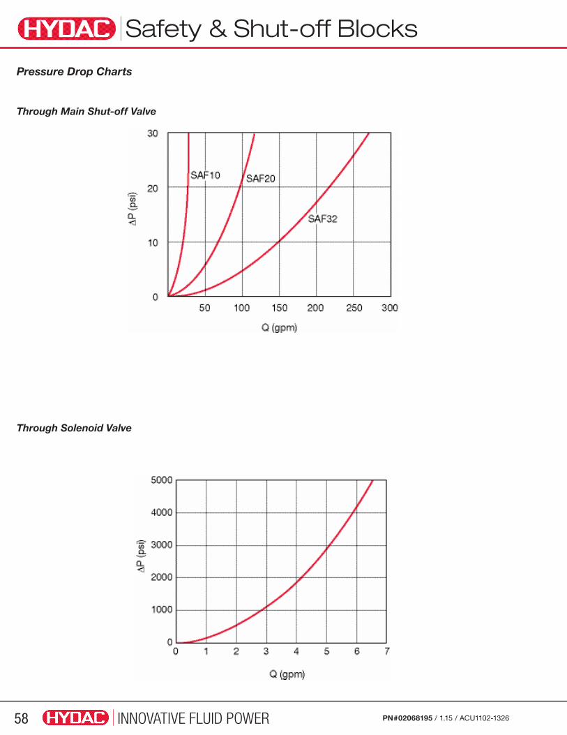
INNOVATIVE FLUID POWER58 PN#02068195 / 1.15 / ACU1102-1326
Pressure Drop Charts
Through Main Shut-off Valve
Through Solenoid Valve
Safety & Shut-off Blocks
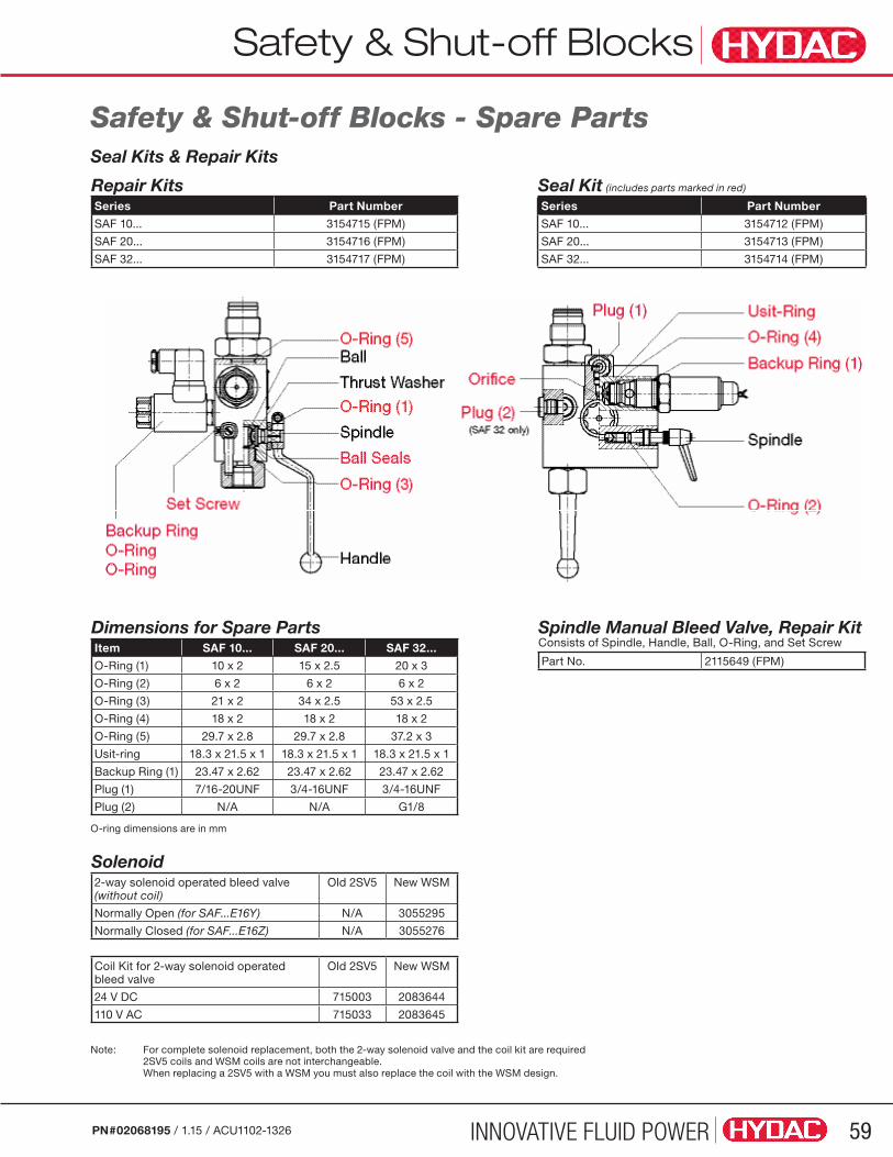
INNOVATIVE FLUID POWER 59PN#02068195 / 1.15 / ACU1102-1326
Safety & Shut-off Blocks
Safety & Shut-off Blocks - Spare PartsSeal Kits & Repair Kits
Note: For complete solenoid replacement, both the 2-way solenoid valve and the coil kit are required 2SV5 coils and WSM coils are not interchangeable.
When replacing a 2SV5 with a WSM you must also replace the coil with the WSM design.
Solenoid2-way solenoid operated bleed valve (without coil)
Old 2SV5 New WSM
Normally Open (for SAF...E16Y) N/A 3055295
Normally Closed (for SAF...E16Z) N/A 3055276
Coil Kit for 2-way solenoid operated bleed valve
Old 2SV5 New WSM
24 V DC 715003 2083644
110 V AC 715033 2083645
Repair Kits Seal Kit (includes parts marked in red)
Series Part Number Series Part Number
SAF 10... 3154715 (FPM) SAF 10... 3154712 (FPM)
SAF 20... 3154716 (FPM) SAF 20... 3154713 (FPM)
SAF 32... 3154717 (FPM) SAF 32... 3154714 (FPM)
Dimensions for Spare PartsItem SAF 10... SAF 20... SAF 32...
O-Ring (1) 10 x 2 15 x 2.5 20 x 3
O-Ring (2) 6 x 2 6 x 2 6 x 2
O-Ring (3) 21 x 2 34 x 2.5 53 x 2.5
O-Ring (4) 18 x 2 18 x 2 18 x 2
O-Ring (5) 29.7 x 2.8 29.7 x 2.8 37.2 x 3
Usit-ring 18.3 x 21.5 x 1 18.3 x 21.5 x 1 18.3 x 21.5 x 1
Backup Ring (1) 23.47 x 2.62 23.47 x 2.62 23.47 x 2.62
Plug (1) 7/16-20UNF 3/4-16UNF 3/4-16UNF
Plug (2) N/A N/A G1/8
O-ring dimensions are in mm
Spindle Manual Bleed Valve, Repair Kit Consists of Spindle, Handle, Ball, O-Ring, and Set Screw
Part No. 2115649 (FPM)
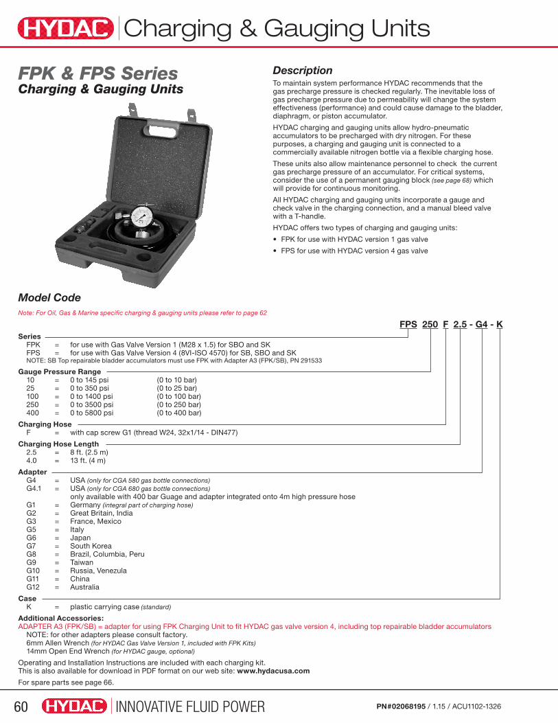
INNOVATIVE FLUID POWER60 PN#02068195 / 1.15 / ACU1102-1326
FPK & FPS SeriesCharging & Gauging Units
DescriptionTo maintain system performance HYDAC recommends that the gas precharge pressure is checked regularly. The inevitable loss of gas precharge pressure due to permeability will change the system effectiveness (performance) and could cause damage to the bladder, diaphragm, or piston accumulator.
HYDAC charging and gauging units allow hydro-pneumatic accumulators to be precharged with dry nitrogen. For these purposes, a charging and gauging unit is connected to a commercially available nitrogen bottle via a flexible charging hose.
These units also allow maintenance personnel to check the current gas precharge pressure of an accumulator. For critical systems, consider the use of a permanent gauging block (see page 68) which will provide for continuous monitoring.
All HYDAC charging and gauging units incorporate a gauge and check valve in the charging connection, and a manual bleed valve with a T-handle.
HYDAC offers two types of charging and gauging units:
• FPK for use with HYDAC version 1 gas valve
• FPS for use with HYDAC version 4 gas valve
Model Code Note: For Oil, Gas & Marine specific charging & gauging units please refer to page 62
FPS 250 F 2.5 - G4 - KSeries FPK = for use with Gas Valve Version 1 (M28 x 1.5) for SBO and SK FPS = for use with Gas Valve Version 4 (8VI-ISO 4570) for SB, SBO and SK NOTE: SB Top repairable bladder accumulators must use FPK with Adapter A3 (FPK/SB), PN 291533
Gauge Pressure Range 10 = 0 to 145 psi (0 to 10 bar) 25 = 0 to 350 psi (0 to 25 bar) 100 = 0 to 1400 psi (0 to 100 bar) 250 = 0 to 3500 psi (0 to 250 bar) 400 = 0 to 5800 psi (0 to 400 bar)
Charging Hose F = with cap screw G1 (thread W24, 32x1/14 - DIN477)
Charging Hose Length 2.5 = 8 ft. (2.5 m) 4.0 = 13 ft. (4 m)
Adapter G4 = USA (only for CGA 580 gas bottle connections) G4.1 = USA (only for CGA 680 gas bottle connections) only available with 400 bar Guage and adapter integrated onto 4m high pressure hose G1 = Germany (integral part of charging hose) G2 = Great Britain, India G3 = France, Mexico G5 = Italy G6 = Japan G7 = South Korea G8 = Brazil, Columbia, Peru G9 = Taiwan G10 = Russia, Venezula G11 = China G12 = Australia
Case K = plastic carrying case (standard)
Additional Accessories: ADAPTER A3 (FPK/SB) = adapter for using FPK Charging Unit to fit HYDAC gas valve version 4, including top repairable bladder accumulators NOTE: for other adapters please consult factory. 6mm Allen Wrench (for HYDAC Gas Valve Version 1, included with FPK Kits) 14mm Open End Wrench (for HYDAC gauge, optional)
Operating and Installation Instructions are included with each charging kit. This is also available for download in PDF format on our web site: www.hydacusa.com
For spare parts see page 66.
Charging & Gauging Units
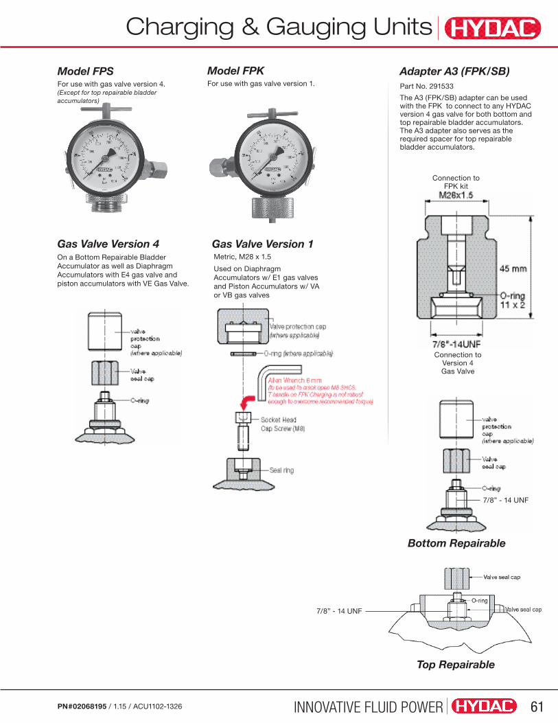
INNOVATIVE FLUID POWER 61PN#02068195 / 1.15 / ACU1102-1326
Charging & Gauging Units
Model FPKFor use with gas valve version 1.
Model FPSFor use with gas valve version 4. (Except for top repairable bladder accumulators)
Adapter A3 (FPK/SB) Part No. 291533
The A3 (FPK/SB) adapter can be used with the FPK to connect to any HYDAC version 4 gas valve for both bottom and top repairable bladder accumulators. The A3 adapter also serves as the required spacer for top repairable bladder accumulators.
Gas Valve Version 1Gas Valve Version 4On a Bottom Repairable Bladder Accumulator as well as Diaphragm Accumulators with E4 gas valve and piston accumulators with VE Gas Valve.
Metric, M28 x 1.5
Used on Diaphragm Accumulators w/ E1 gas valves and Piston Accumulators w/ VA or VB gas valves
Top Repairable
7/8” - 14 UNF
Bottom Repairable
7/8” - 14 UNF
Connection to Version 4 Gas Valve
Connection to FPK kit

INNOVATIVE FLUID POWER62 PN#02068195 / 1.15 / ACU1102-1326
DescriptionTo maintain system performance HYDAC recommends that the gas precharge pressure is checked regularly. The inevitable loss of gas precharge pressure due to permeability will change the system effectiveness (performance) and could cause damage to the bladder, diaphragm, or piston accumulator.
HYDAC charging and gauging units allow hydro-pneumatic accumulators to be precharged with dry nitrogen. For these purposes, a charging and gauging unit is connected to a commercially available nitrogen bottle via a flexible charging hose.
These units also allow maintenance personnel to check the current gas precharge pressure of an accumulator. For critical systems, consider the use of a permanent gauging block (see page 68) which will provide for continuous monitoring.
All HYDAC charging and gauging units incorporate a gauge and check valve in the charging connection, and a manual bleed valve with a T-handle.
This charging kit is used for oil & gas / offshore type accumulators having the repairable 2 piece gas valve (denoted by “11” in the gas port segment in the accumulator model code.
Model CodeFPO 210 F 3 - K
Charging and Gauging Unit FPO = for use with Gas Valve Version 4 (8VI-ISO 4570) for SB, SBO and SK
Gauge Pressure Range 210 = 0 to 3000 psi (0 to 210 bar)
Charging Hose F = with nitrogen bottle connection CGA-580
Charging Hose Length 3.0 = 10 ft. (3 m)
Case K = plastic carrying case (standard)
Additional Accessories: Gas Valve Extension Rod - to be used with top repairable accumulators
Operating and Installation Instructions are included with each charging kit. This is also available for download in PDF format on our web site: www.hydacusa.com
Spare PartsPart Description Item Quantity Part No.
FPO 210 Replacement Kit consists of: 2083385
Pressure Gauge, 3000 PSI 1 1 2701622
T-Handle Lock Chuck 2 1 2701615
Charging Manifold, FPO 3 1 consult factory
Tank Valve 4 1 2701617
Bleeder Valve 5 1 consult factory
Charging Manifold / Bleeder Valve Assembly 3 / 5 2089952
Hose Assembly FPO 210 (CGA 580) consists of: 2086622
High Pressure Coupling (swivel) 1/8” NPT 6 1 2701590
Hose, FPO 3000 PSI, 3m 7 1 2701621
Nipple Gland, CGA-580 8 1 2701620
Nut, CGA-580 9 1 2701619
Top Repairable Gas Valve Extension 10 1 2701741
FPO SeriesCharging and Gauging Units
Charging & Gauging Units
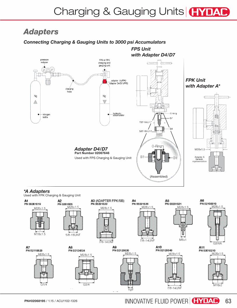
INNOVATIVE FLUID POWER 63PN#02068195 / 1.15 / ACU1102-1326
Charging & Gauging Units
AdaptersConnecting Charging & Gauging Units to 3000 psi Accumulators
Adapter D4/D7 Part Number 02067646
Used with FPS Charging & Gauging Unit
FPS Unit with Adapter D4/D7
FPK Unit with Adapter A*
*A Adapters Used with FPK Charging & Gauging Unit
(Assembled)
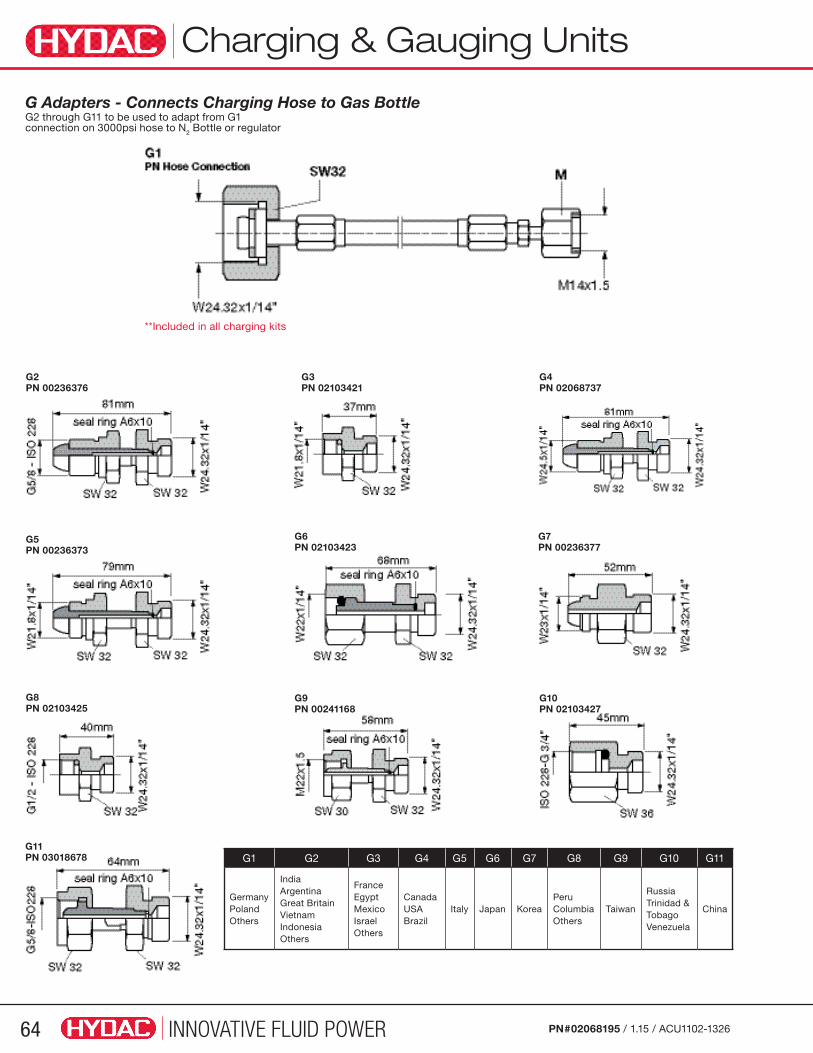
INNOVATIVE FLUID POWER64 PN#02068195 / 1.15 / ACU1102-1326
Charging & Gauging Units
G Adapters - Connects Charging Hose to Gas Bottle G2 through G11 to be used to adapt from G1 connection on 3000psi hose to N2 Bottle or regulator
G2PN 00236376
G6PN 02103423
G9PN 00241168
G3PN 02103421
G4PN 02068737
G7PN 00236377
G10PN 02103427
G5PN 00236373
G8PN 02103425
G11PN 03018678 G1 G2 G3 G4 G5 G6 G7 G8 G9 G10 G11
GermanyPolandOthers
IndiaArgentinaGreat BritainVietnamIndonesiaOthers
France EgyptMexicoIsrael Others
CanadaUSABrazil
Italy Japan KoreaPeruColumbiaOthers
Taiwan
RussiaTrinidad & TobagoVenezuela
China
**Included in all charging kits
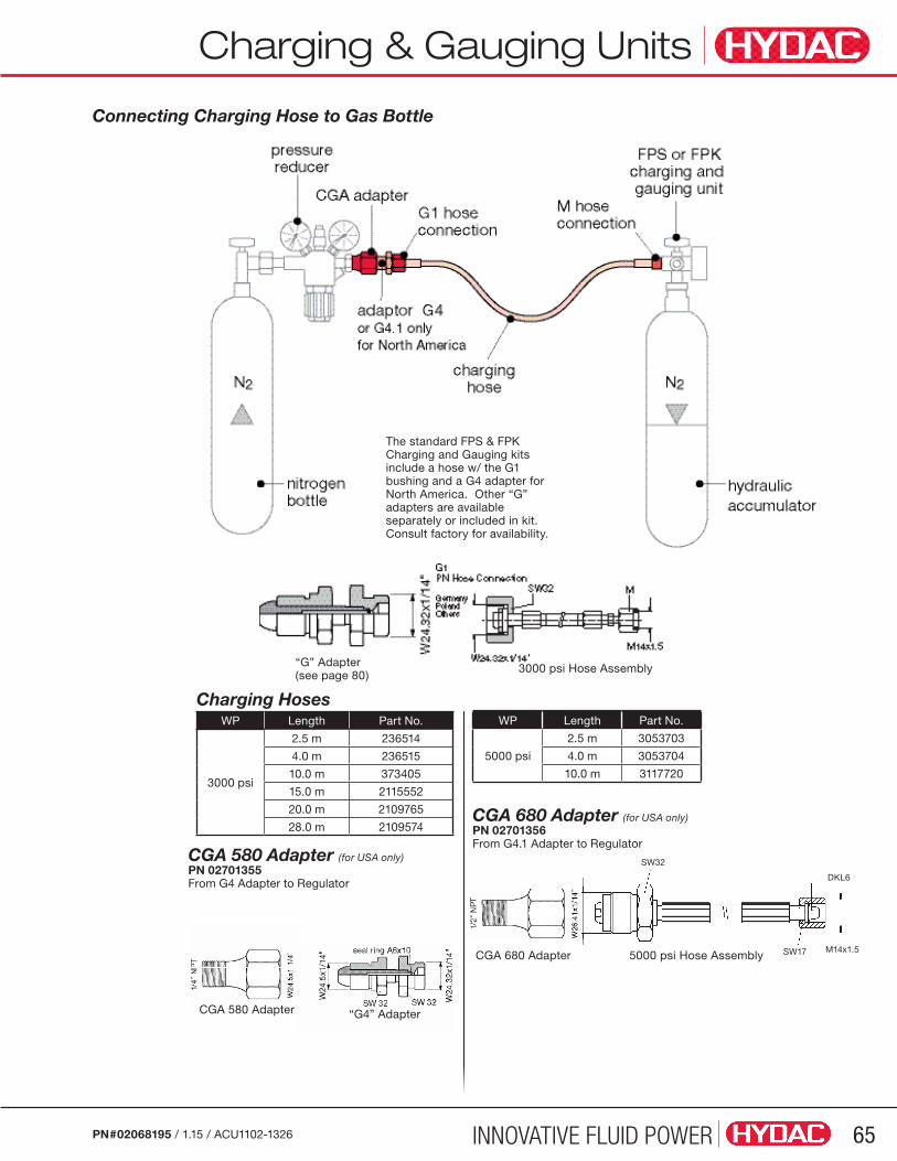
INNOVATIVE FLUID POWER 65PN#02068195 / 1.15 / ACU1102-1326
Charging & Gauging Units
Connecting Charging Hose to Gas Bottle
Charging HosesWP Length Part No.
3000 psi
2.5 m 236514
4.0 m 236515
10.0 m 373405
15.0 m 2115552
20.0 m 2109765
28.0 m 2109574
CGA 580 Adapter (for USA only) PN 02701355From G4 Adapter to Regulator
WP Length Part No.
5000 psi
2.5 m 3053703
4.0 m 3053704
10.0 m 3117720
The standard FPS & FPK Charging and Gauging kits include a hose w/ the G1 bushing and a G4 adapter forNorth America. Other “G” adapters are available separately or included in kit. Consult factory for availability.
SW32
SW17
DKL6
M14x1.5
CGA 680 Adapter (for USA only) PN 02701356From G4.1 Adapter to Regulator
“G4” Adapter
“G” Adapter(see page 80)
3000 psi Hose Assembly
5000 psi Hose AssemblyCGA 680 Adapter
CGA 580 Adapter

INNOVATIVE FLUID POWER66 PN#02068195 / 1.15 / ACU1102-1326
Item Description Part No.
9 O-Ring 601032
10 Seal-Ring 601228
11 Gauge (select pressure range below)
10 (0 to 145 psi) 606759
25 (0 to 350 psi) 606760
100 (0 to 1400 psi) 606761
250 (0 to 3600 psi) 606762
400 (0 to 5800 psi) 606763
12 Check Valve 610004
13 Manual Bleed Valve 236445
23O-Ring - FPS 626488
O-Ring - FPK 601049
- 2.5m Hose 236514
- 4m Hose 236515
- 10m Hose 373405
- ADAPTER G4 2068737
- ADAPTER A3 (FPK/SB) 291533
- O-Ring - ADAPTER A3 (FPK/SB) 601964
WARNING: Only qualified persons should perform maintenance on any type of accumulator. Complete maintenance instructions are available - Contact HYDAC.
Charging & Gauging UnitsSpare Parts FPS Unit FPK Unit
Charging & Gauging Units
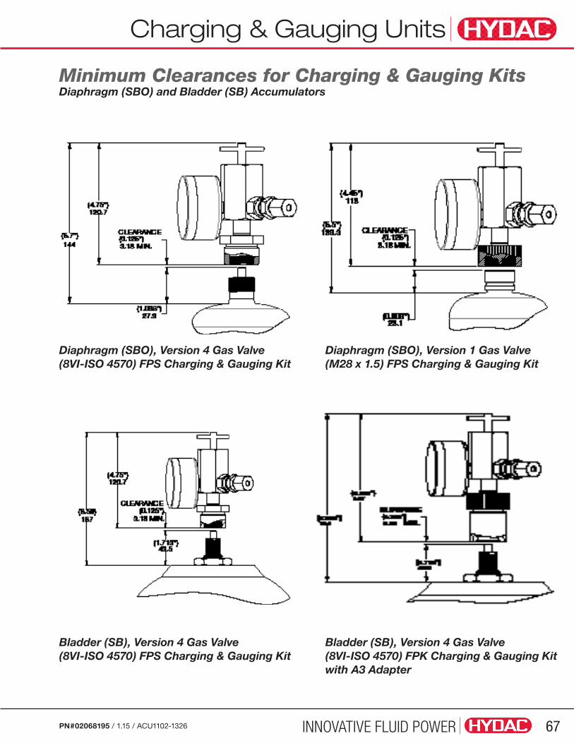
INNOVATIVE FLUID POWER 67PN#02068195 / 1.15 / ACU1102-1326
Charging & Gauging Units
Minimum Clearances for Charging & Gauging KitsDiaphragm (SBO) and Bladder (SB) Accumulators
Diaphragm (SBO), Version 4 Gas Valve (8VI-ISO 4570) FPS Charging & Gauging Kit
Bladder (SB), Version 4 Gas Valve (8VI-ISO 4570) FPS Charging & Gauging Kit
Diaphragm (SBO), Version 1 Gas Valve (M28 x 1.5) FPS Charging & Gauging Kit
Bladder (SB), Version 4 Gas Valve (8VI-ISO 4570) FPK Charging & Gauging Kitwith A3 Adapter

INNOVATIVE FLUID POWER68 PN#02068195 / 1.15 / ACU1102-1326
Permanent Gauging Blocks
Permanent Gauging Block
Model CodePERM GAUGING BLOCK VER4 850
Series Perm Gauging Block
Gas Valve Type VER1 = HYDAC gas valve version 1 (M28x1.5) VER4 = HYDAC gas valve version 4 (7/8”-14UNF)
Accumulator Type (omit) = Bottom Repairable (standard) TR = Top Repairable TR S11 = Top Repairable (Oil & Gas / Offshore)
Gauge Pressure Range 850 = 0 to 850 psi 1450 = 0 to 1450 psi 2300 = 0 to 2300 psi 3600 = 0 to 3600 psi 5800 = 0 to 5800 psi
DescriptionThe HYDAC Permanent Gauging Block allows constant monitoring of gas pressure while a system is in operation. This helps users monitor pressure loss, and determine when charging is needed. They are designed to fit bladder, diaphragm, and piston style accumulators with HYDAC Gas Valve Version 4. Use of these blocks facilitates trouble shooting and simplifies maintenance by eliminating the need to attach a charging and gauging unit to monitor pressure. Charging of the accumulator is accomplished by simply attaching a HYDAC charging kit to the gas valve on top of the Permanent Gauging Block in exactly the same manner as attaching to an accumulator without the Permanent Gauging Block.
Special Tools Required• Charging and Gauging Unit
• Gas Valve Core Tool
• 50 mm Open End Wrench (for bottom repairable accumulator)
• 32 mm Open End Wrench (for top repairable accumulator)
• Torque Wrench(es)
Note: The gas valve core (for Version 4) or the M8 SHCS (for Version 1) gas valves must be removed to allow unrestricted gas flow from the accumulator into the Permanent Gauge Block. Read all instructions thoroughly before beginning any type of service or repair work Refer to additional information contained in the “Operating and Installation Instructions for HYDAC Accumulators.”
TRS11

INNOVATIVE FLUID POWER 69PN#02068195 / 1.15 / ACU1102-1326
Permanent Gauging Blocks
Bottom Repairable Bladder
Installation Drawings Permanent Gauging Blocks for HYDAC Gas Valve Version 4
Bottom Repairable Bladder with M50 Gas Valve
Piston & DiaphragmTop Repairable Bladder
3 Gas Valve Core
4 Lock Nut
5 Valve Seal Cap
7 O-ring (7.5 x 2)
8 Name Plate
Parts Legend
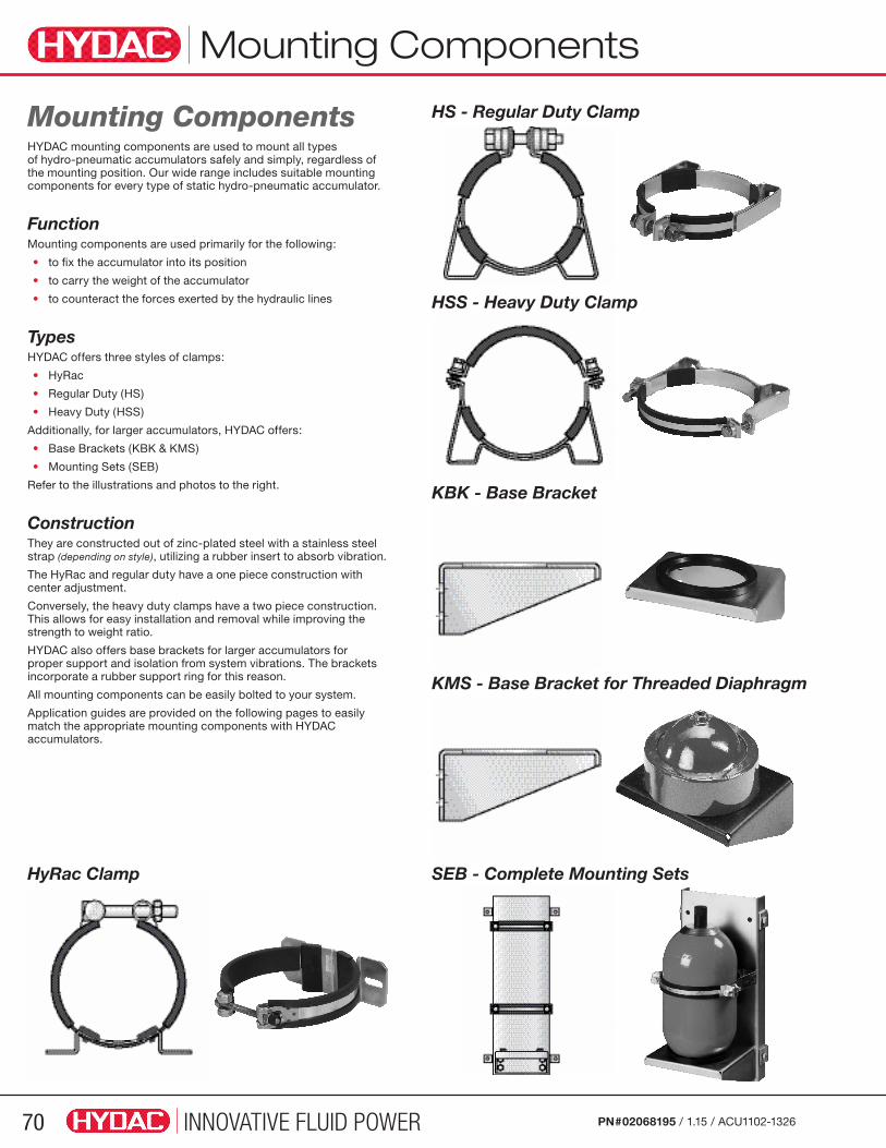
INNOVATIVE FLUID POWER70 PN#02068195 / 1.15 / ACU1102-1326
Mounting Components
Mounting ComponentsHYDAC mounting components are used to mount all types of hydro-pneumatic accumulators safely and simply, regardless of the mounting position. Our wide range includes suitable mounting components for every type of static hydro-pneumatic accumulator.
FunctionMounting components are used primarily for the following:
• to fix the accumulator into its position
• to carry the weight of the accumulator
• to counteract the forces exerted by the hydraulic lines
TypesHYDAC offers three styles of clamps:
• HyRac
• Regular Duty (HS)
• Heavy Duty (HSS)
Additionally, for larger accumulators, HYDAC offers:
• Base Brackets (KBK & KMS)
• Mounting Sets (SEB)
Refer to the illustrations and photos to the right.
ConstructionThey are constructed out of zinc-plated steel with a stainless steel strap (depending on style), utilizing a rubber insert to absorb vibration.
The HyRac and regular duty have a one piece construction with center adjustment.
Conversely, the heavy duty clamps have a two piece construction. This allows for easy installation and removal while improving the strength to weight ratio.
HYDAC also offers base brackets for larger accumulators for proper support and isolation from system vibrations. The brackets incorporate a rubber support ring for this reason.
All mounting components can be easily bolted to your system.
Application guides are provided on the following pages to easily match the appropriate mounting components with HYDAC accumulators.
HyRac Clamp
HS - Regular Duty Clamp
HSS - Heavy Duty Clamp
KBK - Base Bracket
KMS - Base Bracket for Threaded Diaphragm
SEB - Complete Mounting Sets
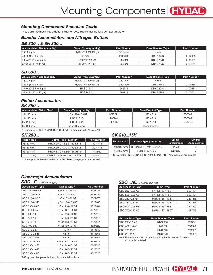
INNOVATIVE FLUID POWER 71PN#02068195 / 1.15 / ACU1102-1326
Mounting Components
Mounting Component Selection GuideThese are the mounting solutions that HYDAC recommends for each accumulator
SB 330... & SN 330...Accumulator Size (capacity) Clamp Type (quantity) Part Number Base Bracket Type Part Number
1 (0.25 gal) HyRac 110-118 ST (1) 3627484 None
4 to 6 (1 to 1.5 gal) HS 167 (1) 2110642 KBK 167/G 2107989
10 to 20 (2.5 to 5 gal) HSS 222/229 (1) 235224 KBK 222/G 2100651
32 to 54 (10 to 15 gal) HSS 222/229 (2) 235224 KBK 222/G 2100651
SB 600...Accumulator Size (capacity) Clamp Type (quantity) Part Number Base Bracket Type Part Number
1 (0.25 gal) HyRac 121-129 ST (1) 3627515 None
4 to 6 (1 to 1.5 gal) HyRac 167-175 ST (1) 3627520 KBK 167/G 2107989
10 to 20 (2.5 to 5 gal) HSS 242 (1) 362712 KBK 222/G 2100651
32 to 54 (10 to 15 gal) HSS 242 (2) 362712 KBK 222/G 2100651
SBO...E... (Welded type)
Accumulator Type Clamp Type(2 Part Number
SBO 250-0.075 E HyRac 62-65 ST 3627423
SBO 210-0.16 E HyRac 73-76 ST 3627424
SBO 210-0.32 E HyRac 89-92 ST 3627475
SBO 210-0.5 E HyRac 100-105 ST 3627480
SBO 330-0.6 E HyRac 110-118 ST 3627484
SBO 210-0.75 E HyRac 121-129 ST 3627515
SBO 200-1 E HyRac 133-142 ST 3627516
SBO 140-1.4 E HyRac 143-151 ST 3627517
SBO 210-1.4 E HyRac 143-151 ST 3627517
SBO 100-2 E HyRac 160-167 ST 3627520
SBO 210-2 E HS 167 2110642
SBO 210-2.8 E HS 167 2110642
SBO 250-3.5 E HS 167 2110642
SBO 330-0.75 E HyRac 121-129 ST 3627515
SBO 330-1.4 E HyRac 143-151 ST 3627517
SBO 330-2.0 E HyRac 167-175 ST 3627520
SBO 330-3.5 E HyRac 167-175 ST 3627520
SK 350...Accumulator Piston Size(1 Clamp Type (quantity) Part Number Base Bracket Type Part Number
15 (150 mm) HyRac 176-185 ST 3627522 KBK 219 238042
18 (180 mm) HSS 219 (2) 237401 KBK 219 238042
25 (250 mm) HSS 310 (2) 237389 KBK 310 238043
35 (355 mm) consult factory consult factory
1) Example: SK350-20/2112S-210FCF-VE-18 (see page 35 for details)
SBO...A6... (Threaded type)
Accumulator Type Clamp Type Part Number
SBO 350-0.25 A6 HyRac 110-118 ST 3627484
SBO 500-0.25 A6 HyRac 110-118 ST 3627484
SBO 250-0.6 A6 HyRac 133-142 ST 3627516
SBO 330-0.6 A6 HyRac 133-142 ST 3627516
SBO 600-0.25 A6 HyRac 143-151 ST 3627517
SBO 750-0.25 A6 HyRac 143-151 ST 3627517
Accumulator Type Base Bracket Type Part Number
SBO 210-1.3 A6 KMS 200 359931
SBO 400-1.3 A6 KMS 210 358989
SBO 180-2 A6 KMS 220 359922
SBO 250-2 A6 KMS 220 359922
Bladder Accumulators and Nitrogen Bottles
Piston Accumulators
Diaphragm Accumulators
Note: Either one clamp or one Base Bracket is needed for each accumulator listed.
2) Only one clamp needed for all accumulators listed.
SK 280...Piston Size(1 Clamp Type (quantity) Part Number
05 (50 mm) HRGKSM 0 R 58-61/62 ST (2) 3018442
06 (60 mm) HRGKSM 0 R 70-73/73 ST (2) 3018444
08 (80 mm) HRGKSM 0 R 92-95/96 ST (2) 444995
10 (100 mm) HRGKSM 0 R 119-127/124 ST (2) 444505
1) Example: SK280-1/3218U-280 AAD VB 05 (see page 34 for details)
SK 210...15HPiston Size(1 Clamp Type (quantity)
Clamp Part Number
Qty Per Accumulator
10 (100 mm) HRGKSM 1 R 119-127/124 ST 444505 2
15 (150 mm) HyRac 167-175 ST 3627520 2
1) Example: SK210-20/3218S-210ACM-KCH-15H (see page 32 for details)

INNOVATIVE FLUID POWER72 PN#02068195 / 1.15 / ACU1102-1326
Mounting Components
Dimensions Use the Selection Guide on page 71 to select the appropriate components.
HyRac - Stainless Steel Strap with swivel-bolt adjustment
Clamp Model A B C D (range) E H L S Weight
kg (lbs)
HyRac 62-65 ST 1204.72
853.34
903.54
62-652.4-2.6
401.6
39-40.51.5-1.6
60.24
30.12
0.16(0.35)
HyRac 73-76 ST 1204.72
853.34
1013.98
73-762.9-3.0
401.6
49.5-461.9-1.8
60.24
30.12
0.16(0.35)
HyRac 89-92 ST 1204.72
853.34
1164.57
89-923.5-3.6
401.6
51.5-532.0-2.1
60.24
30.12
0.17(0.37)
HyRac 100-105 ST 1566.14
1003.94
1355.31
100-1053.9-4.1
602.4
59-622.3-2.4
180.71
30.12
0.40(0.88)
HyRac 106-114 ST 1566.14
1003.94
1435.63
106-1144.2-4.5
602.4
62.5-662.5-2.6
180.71
30.12
0.41(0.9)
HyRac 110-118 ST 1566.14
1003.94
1566.14
110-1184.3-4.6
602.4
72.5-772.8-3.0
180.71
30.12
0.42(0.93)
HyRac 121-129 ST 1566.14
1003.91
1656.50
121-1294.8-5.1
602.4
75.5-803.0-3.1
180.71
30.12
0.43(0.95)
HyRac 133-142 ST 1566.14
1003.91
1746.85
133-1425.2-5.6
602.4
76.5-823.0-3.2
180.71
30.12
0.44(0.97)
HyRac 143-151 ST 1566.14
1003.91
1827.17
143-1515.6-5.9
602.4
83-86.53.3-3.4
180.71
30.12
0.45(0.99)
HyRac 152-159 ST 1566.14
1003.91
1917.52
152-1596.0-6.3
602.4
87-913.4-3.6
180.71
30.12
0.46(1.01)
HyRac 160-167 ST 2369.29
1525.98
1977.76
160-1676.3-6.6
602.4
89-933.5-3.7
321.3
40.16
0.7(1.54)
HyRac 167-175 ST 2369.29
1525.98
2078.15
167-1756.6-6.9
602.4
92.5-96.53.6-3.8
321.3
40.16
0.72(1.59)
HyRac 202-210 ST 2369.29
1525.98
2459.65
202-2107.9-8.3
602.4
116-1204.6-4.7
321.3
40.16
0.76 (1.68)
HyRac 209-217 ST 2369.29
1525.98
25510.04
209-2178.2-8.5
602.4
122.5-126.54.8-5.0
321.3
40.16
0.77(1.70)
HS - Regular Duty Clamp, with single center adjustment
Clamp Model D D (range) A B C (ref.) H ØL Z Weight kg.(lbs)
HS 167 1676.57
164-1706.46-6.69
1857.28
1536.02
2118.31
92.53.64
90.35
301.18
0.92.0
HSS - Heavy Duty Clamp with two-piece constructionClamp Model D D (range) A B C
(ref.) H K ØL Z Weight kg.(lbs)
HSS 219 2198.62
216-2228.50-8.74
26810.55
2168.50
2409.45
1234.84
28511.22
150.59
401.57
1.73.8
HSS 222/229 2268.90
220-2318.66-9.10
27010.63
2168.50
2449.61
1234.84
29511.61
150.59
401.57
1.73.8
HSS 242 2429.53
231-2429.10-9.53
26810.55
2168.50
26510.43
1365.35
30512.01
150.59
401.57
1.73.8
HSS 286 28611.26
283-28911.14-11.38
33213.07
28011.02
31412.36
1636.42
35513.98
150.59
401.57
2.14.6
HSS 310 31012.20
307-31312.09-12.32
33213.07
28011.02
33313.11
1706.69
38014.96
150.59
401.57
2.14.6
Dimensions are in mm with inches shown below.Dimensions are for general information only, All critical dimensions should be verified.
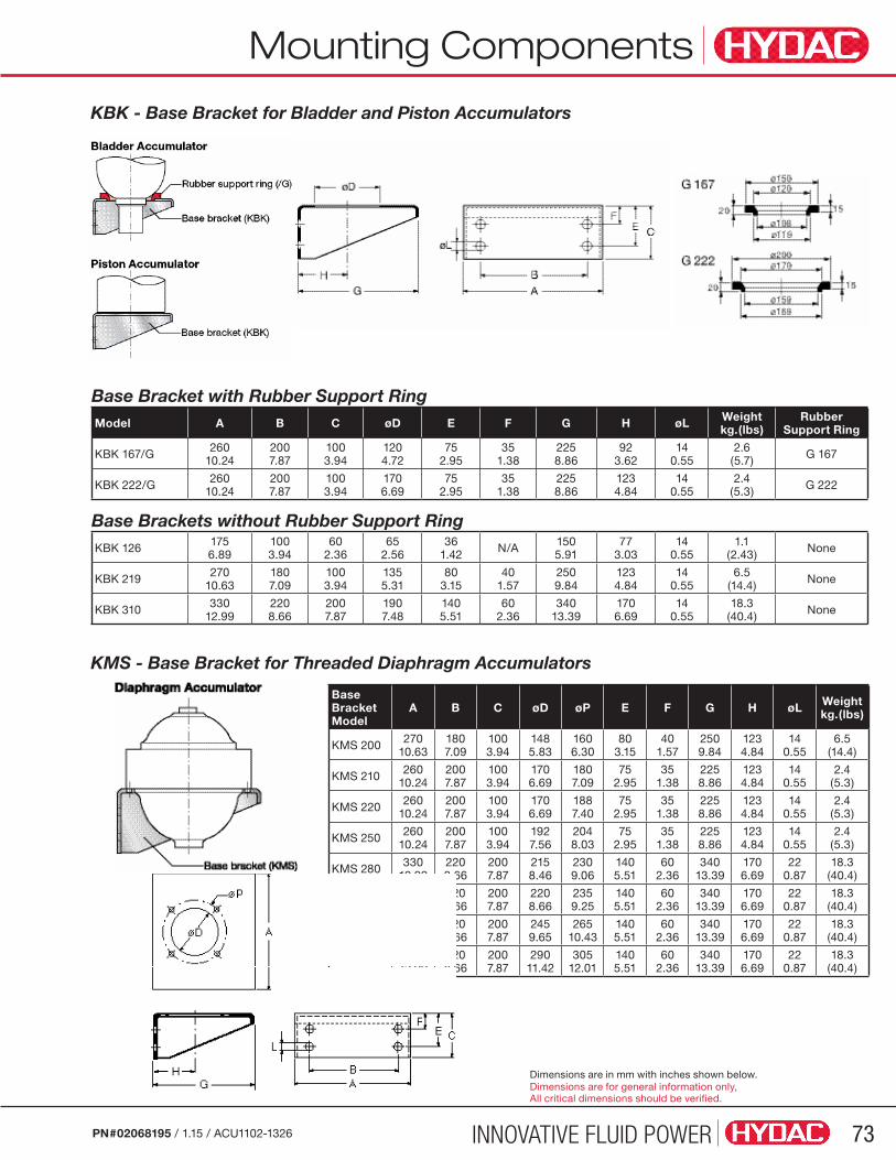
INNOVATIVE FLUID POWER 73PN#02068195 / 1.15 / ACU1102-1326
Mounting Components
KBK - Base Bracket for Bladder and Piston Accumulators
Base Bracket with Rubber Support RingModel A B C øD E F G H øL Weight
kg.(lbs)Rubber
Support Ring
KBK 167/G 26010.24
2007.87
1003.94
1204.72
752.95
351.38
2258.86
923.62
140.55
2.6(5.7) G 167
KBK 222/G 26010.24
2007.87
1003.94
1706.69
752.95
351.38
2258.86
1234.84
140.55
2.4(5.3) G 222
Base Brackets without Rubber Support RingKBK 126 175
6.891003.94
602.36
652.56
361.42 N/A 150
5.9177
3.0314
0.551.1
(2.43) None
KBK 219 27010.63
1807.09
1003.94
1355.31
803.15
401.57
2509.84
1234.84
140.55
6.5(14.4) None
KBK 310 33012.99
2208.66
2007.87
1907.48
1405.51
602.36
34013.39
1706.69
140.55
18.3(40.4) None
KMS - Base Bracket for Threaded Diaphragm Accumulators
Base Bracket Model
A B C øD øP E F G H øL Weight kg.(lbs)
KMS 200 27010.63
1807.09
1003.94
1485.83
1606.30
803.15
401.57
2509.84
1234.84
140.55
6.5(14.4)
KMS 210 26010.24
2007.87
1003.94
1706.69
1807.09
752.95
351.38
2258.86
1234.84
140.55
2.4(5.3)
KMS 220 26010.24
2007.87
1003.94
1706.69
1887.40
752.95
351.38
2258.86
1234.84
140.55
2.4(5.3)
KMS 250 26010.24
2007.87
1003.94
1927.56
2048.03
752.95
351.38
2258.86
1234.84
140.55
2.4(5.3)
KMS 280 33012.99
2208.66
2007.87
2158.46
2309.06
1405.51
602.36
34013.39
1706.69
220.87
18.3(40.4)
KMS 300 33012.99
2208.66
2007.87
2208.66
2359.25
1405.51
602.36
34013.39
1706.69
220.87
18.3(40.4)
KMS 310 33012.99
2208.66
2007.87
2459.65
26510.43
1405.51
602.36
34013.39
1706.69
220.87
18.3(40.4)
KMS 320 33012.99
2208.66
2007.87
29011.42
30512.01
1405.51
602.36
34013.39
1706.69
220.87
18.3(40.4)
Dimensions are in mm with inches shown below.Dimensions are for general information only, All critical dimensions should be verified.
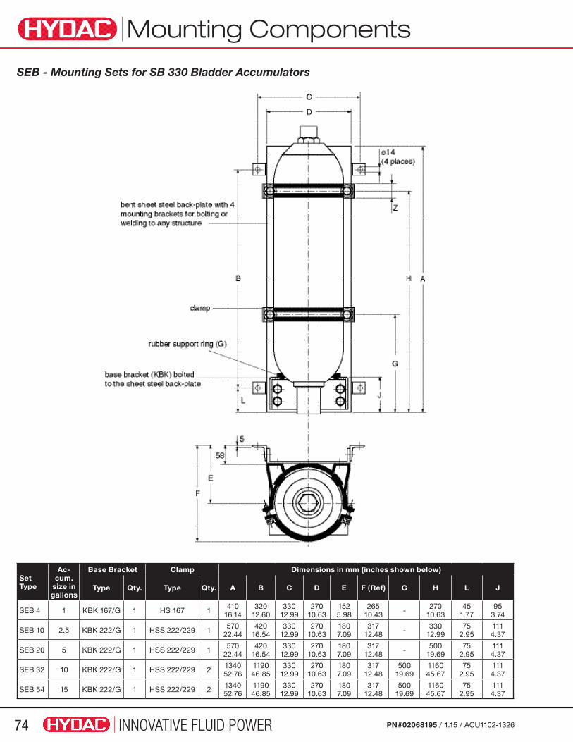
INNOVATIVE FLUID POWER74 PN#02068195 / 1.15 / ACU1102-1326
Mounting Components
SEB - Mounting Sets for SB 330 Bladder Accumulators
Set Type
Ac-cum.
size in gallons
Base Bracket Clamp Dimensions in mm (inches shown below)
Type Qty. Type Qty. A B C D E F (Ref) G H L J
SEB 4 1 KBK 167/G 1 HS 167 1 41016.14
32012.60
33012.99
27010.63
1525.98
26510.43 - 270
10.6345
1.7795
3.74
SEB 10 2.5 KBK 222/G 1 HSS 222/229 1 57022.44
42016.54
33012.99
27010.63
1807.09
31712.48 - 330
12.9975
2.951114.37
SEB 20 5 KBK 222/G 1 HSS 222/229 1 57022.44
42016.54
33012.99
27010.63
1807.09
31712.48 - 500
19.6975
2.951114.37
SEB 32 10 KBK 222/G 1 HSS 222/229 2 134052.76
119046.85
33012.99
27010.63
1807.09
31712.48
50019.69
116045.67
752.95
1114.37
SEB 54 15 KBK 222/G 1 HSS 222/229 2 134052.76
119046.85
33012.99
27010.63
1807.09
31712.48
50019.69
116045.67
752.95
1114.37

INNOVATIVE FLUID POWER 75PN#02068195 / 1.15 / ACU1102-1326
Typical ApplicationsThere are three common applications for Accumulators:
• (A) Shock Absorption
• (B) Pulsation Dampening
• (C) Energy Storage
The pages and sizing forms that follow can be used as a guide.
These forms are available online at www.hydacusa.com
Pulsation Dampeners for Displacement PumpsThe non uniformity of displacement pumps creates pulsations in the fluid which can be dampened with a pulsation dampener.
Energy Storage - Emergency Brakes Emergency actuation, the accumulator provides the stored hydraulic energy to apply the brake should the main power source fail.
Shock Absorption - Spring Element The compressibility of the gas in the accumulator works like a spring. By throttling the flow in and out of the accumulator, the spring stiffness can be adjusted.
Applications
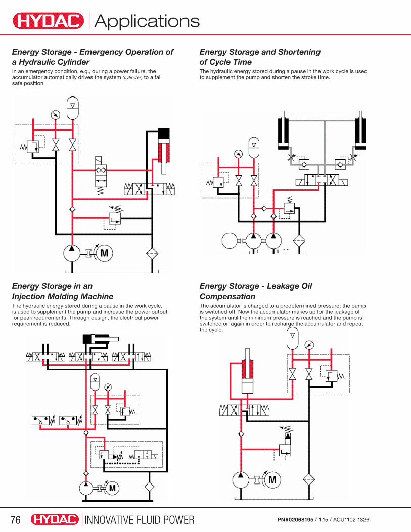
INNOVATIVE FLUID POWER76 PN#02068195 / 1.15 / ACU1102-1326
Energy Storage - Emergency Operation of a Hydraulic Cylinder In an emergency condition, e.g., during a power failure, the accumulator automatically drives the system (cylinder) to a fail safe position.
Energy Storage and Shortening of Cycle Time The hydraulic energy stored during a pause in the work cycle is used to supplement the pump and shorten the stroke time.
Energy Storage in an Injection Molding Machine The hydraulic energy stored during a pause in the work cycle, is used to supplement the pump and increase the power output for peak requirements. Through design, the electrical power requirement is reduced.
Energy Storage - Leakage Oil Compensation The accumulator is charged to a predetermined pressure; the pump is switched off. Now the accumulator makes up for the leakage of the system until the minimum pressure is reached and the pump is switched on again in order to recharge the accumulator and repeat the cycle.
Applications

INNOVATIVE FLUID POWER 77PN#02068195 / 1.15 / ACU1102-1326
Shock Absorbers
Graphic Example of a Pressure Spike
With AccumulatorWithout Accumulator
For assistance in sizing pulsation dampeners, shock absorbers, and suction stabilizers, please contact the HYDAC Accumulator Group.
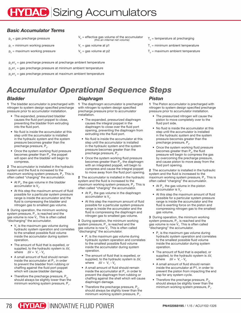
INNOVATIVE FLUID POWER78 PN#02068195 / 1.15 / ACU1102-1326
Sizing Accumulators
Basic Accumulator Terms
Accumulator Operational Sequence StepsBladder1 The bladder accumulator is precharged with nitrogen to system design specified precharge pressure prior to accumulator installation.
• The expanded, pressurized bladder causes the fluid port poppet to close, preventing the bladder from extruding into the fluid port.
• No fluid is inside the accumulator at this step until the accumulator is installed in the hydraulic system and the system pressure becomes greater than the precharge pressure, P0.
• Once the system working fluid pressure becomes greater than P0, the poppet will open and the bladder will begin to compress.
2 The accumulator is installed in the hydraulic system and the fluid is increased to the maximum working system pressure, P2. This is often called “charging” the accumulator.
• At P2, the gas volume in the bladder accumulator is V2.
• At this step the maximum amount of fluid possible for a particular system pressure range is inside the accumulator and the fluid is compressing the bladder and nitrogen gas to smallest gas volume.
3 During operation, the minimum working system pressure, P1, is reached and the gas volume is now V1. This is often called “discharging” the accumulator.
• V1 is the maximum gas volume during hydraulic system operation and correlates to the smallest possible fluid volume inside the accumulator during system operation.
• The amount of fluid that is expelled, or supplied, to the hydraulic system is ∆V, where ∆V = V1 - V2
• A small amount of fluid should remain inside the accumulator at P1, in order to prevent the bladder from rubbing or chaffing against the fluid port poppet which will cause bladder damage.
• Therefore the precharge pressure, P0, should always be slightly lower than the minimum working system pressure, P1.
Diaphragm1 The diaphragm accumulator is precharged with nitrogen to system design specified precharge pressure prior to accumulator installation.
• The expanded, pressurized diaphragm causes the integral poppet in the diaphragm to close over the fluid port opening, preventing the diaphragm from extruding into the fluid port.
• No fluid is inside the accumulator at this step until the accumulator is installed in the hydraulic system and the system pressure becomes greater than the precharge pressure, P0.
• Once the system working fluid pressure becomes greater than P0, the diaphragm with an integrated poppet, will begin to compress and cause the integral poppet to move away from the fluid port opening.
2 The accumulator is installed in the hydraulic system and the fluid is increased to the maximum working system pressure, P2. This is often called “charging” the accumulator.
• At P2, the gas volume in the diaphragm accumulator is V2.
• At this step the maximum amount of fluid possible for a particular system pressure range is inside the accumulator and the fluid is compressing the diaphragm and nitrogen gas to smallest gas volume.
3 During operation, the minimum working system pressure, P1, is reached and the gas volume is now V1. This is often called “discharging” the accumulator.
• P1 is the maximum gas volume during hydraulic system operation and correlates to the smallest possible fluid volume inside the accumulator during system operation.
• The amount of fluid that is expelled, or supplied, to the hydraulic system is ∆V, where ∆V = V1 - V2
• A small amount of fluid should remain inside the accumulator at P1, in order to prevent the diaphragm from rubbing or chaffing against the shell which will cause diaphragm damage.
• Therefore the precharge pressure, P0, should always be slightly lower than the minimum working system pressure, P1.
Piston1 The Piston accumulator is precharged with nitrogen to system design specified precharge pressure prior to accumulator installation.
• The pressurized nitrogen will cause the piston to move completely over to the fluid port side.
• No fluid is inside the accumulator at this step until the accumulator is installed in the hydraulic system and the system pressure becomes greater than the precharge pressure, P0.
• Once the system working fluid pressure becomes greater than P0, the fluid pressure will begin to compress the gas by overcoming the precharge pressure, and cause piston to move away from the fluid port opening.
2 The accumulator is installed in the hydraulic system and the fluid is increased to the maximum working system pressure, P2. This is often called “charging” the accumulator.
• At P2, the gas volume in the piston accumulator is V2.
• At this step the maximum amount of fluid possible for a particular system pressure range is inside the accumulator and the fluid is exerting force on the piston and compressing nitrogen gas to the smallest gas volume.
3 During operation, the minimum working system pressure, P1, is reached and the gas volume is now V1. This is often called “discharging” the accumulator.
• P1 is the maximum gas volume during hydraulic system operation and correlates to the smallest possible fluid volume inside the accumulator during system operation.
• The amount of fluid that is expelled, or supplied, to the hydraulic system is ∆V, where ∆V = V1 - V2
• A small amount of fluid should remain inside the accumulator at P1, in order to prevent the piston from impacting the end cap for any system cycle.
• Therefore the precharge pressure, P0, should always be slightly lower than the minimum working system pressure, P1.
p0 = gas precharge pressure V0 = effective gas volume of the accumulator (this an internal net volume) T0 = temperature at precharging
p1 = minimum working pressure V1 = gas volume at p1 T1 = minimum ambient temperature
p2 = maximum working pressure V2 = gas volume at p2 T2 = maximum ambient temperature
p0@T0 = gas precharge pressure at precharge ambient temperature
p0@T1 = gas precharge pressure at minimum ambient temperature
p0@T2 = gas precharge pressure at maximum ambient temperature
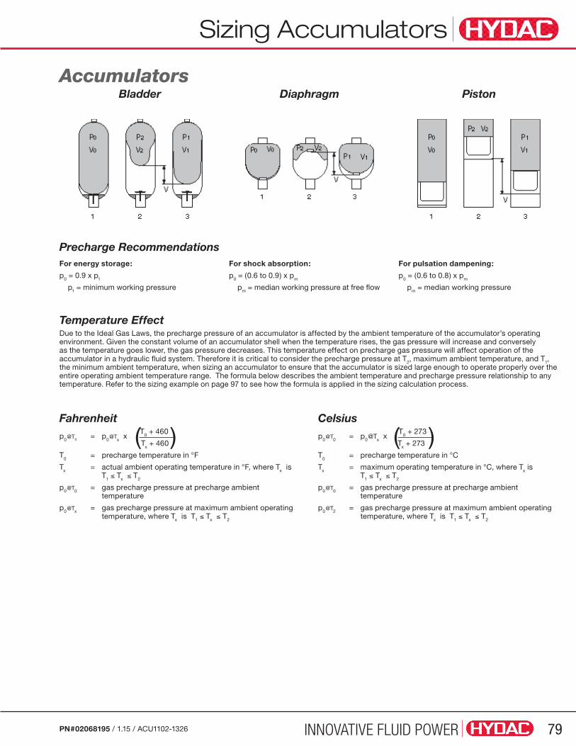
INNOVATIVE FLUID POWER 79PN#02068195 / 1.15 / ACU1102-1326
Accumulators
For energy storage:
p0 = 0.9 x p1
p1 = minimum working pressure
For shock absorption:
p0 = (0.6 to 0.9) x pm
pm = median working pressure at free flow
For pulsation dampening:
p0 = (0.6 to 0.8) x pm
pm = median working pressure
Temperature Effect Due to the Ideal Gas Laws, the precharge pressure of an accumulator is affected by the ambient temperature of the accumulator’s operating environment. Given the constant volume of an accumulator shell when the temperature rises, the gas pressure will increase and conversely as the temperature goes lower, the gas pressure decreases. This temperature effect on precharge gas pressure will affect operation of the accumulator in a hydraulic fluid system. Therefore it is critical to consider the precharge pressure at T2, maximum ambient temperature, and T1, the minimum ambient temperature, when sizing an accumulator to ensure that the accumulator is sized large enough to operate properly over the entire operating ambient temperature range. The formula below describes the ambient temperature and precharge pressure relationship to any temperature. Refer to the sizing example on page 97 to see how the formula is applied in the sizing calculation process.
Fahrenheitp0@T0 = p0@Tx x (T0 + 460 ) Tx + 460
T0 = precharge temperature in °F
Tx = actual ambient operating temperature in °F, where Tx is T1 ≤ Tx ≤ T2
p0@T0 = gas precharge pressure at precharge ambient temperature
p0@Tx = gas precharge pressure at maximum ambient operating temperature, where Tx is T1 ≤ Tx ≤ T2
Celsiusp0@T0 = p0@Tx x (T0 + 273 ) Tx + 273
T0 = precharge temperature in °C
Tx = maximum operating temperature in °C, where Tx is T1 ≤ Tx ≤ T2
p0@T0 = gas precharge pressure at precharge ambient temperature
p0@T2 = gas precharge pressure at maximum ambient operating temperature, where Tx is T1 ≤ Tx ≤ T2
Sizing Accumulators
Bladder Diaphragm Piston
Precharge Recommendations
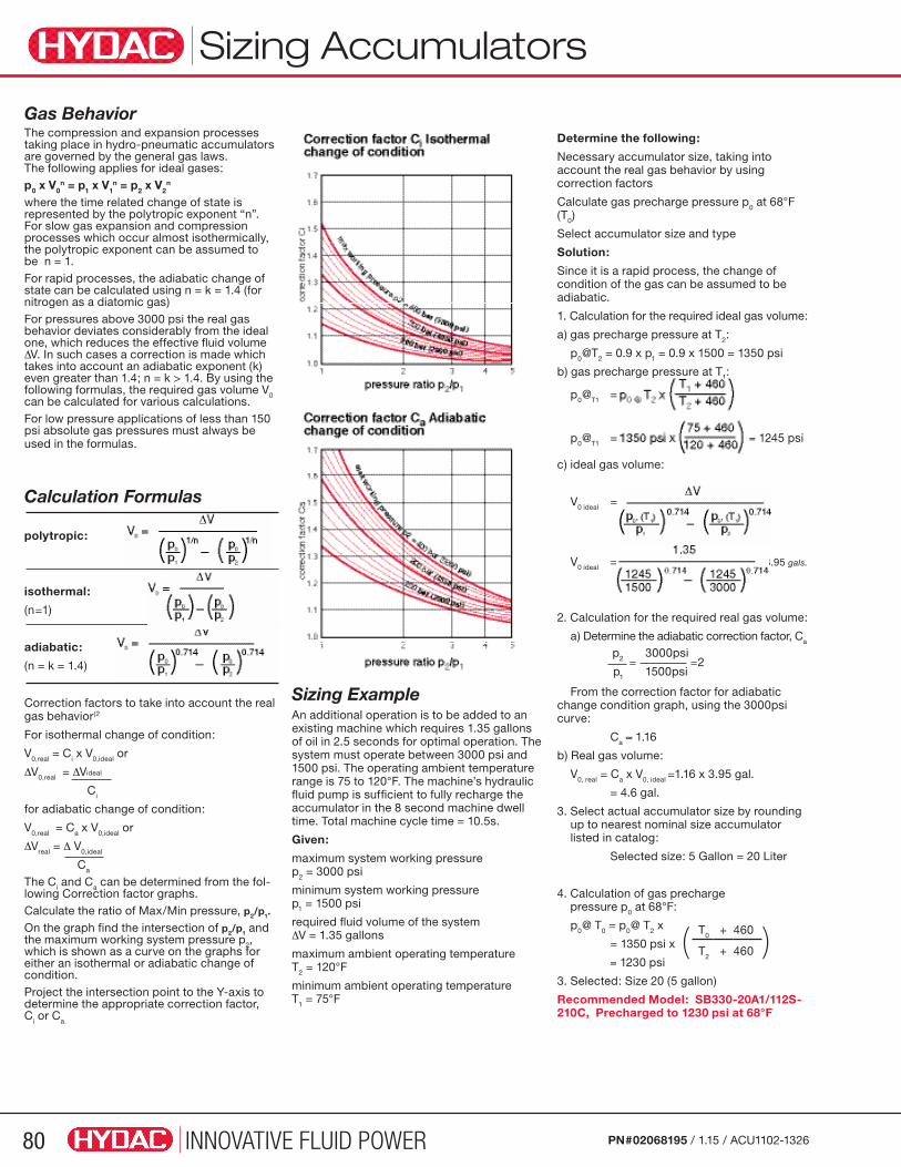
INNOVATIVE FLUID POWER80 PN#02068195 / 1.15 / ACU1102-1326
Determine the following:
Necessary accumulator size, taking into account the real gas behavior by using correction factors
Calculate gas precharge pressure p0 at 68°F (T0)
Select accumulator size and type
Solution:
Since it is a rapid process, the change of condition of the gas can be assumed to be adiabatic.
1. Calculation for the required ideal gas volume:
a) gas precharge pressure at T2:
p0@T2 = 0.9 x p1 = 0.9 x 1500 = 1350 psi
b) gas precharge pressure at T1:
p0@T1 =
p0@T1 = = 1245 psi
c) ideal gas volume:
V0 ideal =
V0 ideal = = 3.95 gals.
2. Calculation for the required real gas volume:
a) Determine the adiabatic correction factor, Ca
From the correction factor for adiabatic change condition graph, using the 3000psi curve:
Ca ≈ 1.16
b) Real gas volume:
V0, real = Ca x V0, ideal =1.16 x 3.95 gal.
= 4.6 gal.
3. Select actual accumulator size by rounding up to nearest nominal size accumulator listed in catalog:
Selected size: 5 Gallon = 20 Liter
4. Calculation of gas precharge pressure p0 at 68°F:
p0@ T0 = p0@ T2 x
= 1350 psi x
= 1230 psi
3. Selected: Size 20 (5 gallon)
Recommended Model: SB330-20A1/112S-210C, Precharged to 1230 psi at 68°F
Gas Behavior The compression and expansion processes taking place in hydro-pneumatic accumulators are governed by the general gas laws. The following applies for ideal gases:p0 x V0
n = p1 x V1n = p2 x V2
n
where the time related change of state is represented by the polytropic exponent “n”. For slow gas expansion and compression processes which occur almost isothermically, the polytropic exponent can be assumed to be n = 1. For rapid processes, the adiabatic change of state can be calculated using n = k = 1.4 (for nitrogen as a diatomic gas) For pressures above 3000 psi the real gas behavior deviates considerably from the ideal one, which reduces the effective fluid volume ∆V. In such cases a correction is made which takes into account an adiabatic exponent (k) even greater than 1.4; n = k > 1.4. By using the following formulas, the required gas volume V0 can be calculated for various calculations.For low pressure applications of less than 150 psi absolute gas pressures must always be used in the formulas.
Calculation Formulas
polytropic:
isothermal:
(n=1)
adiabatic:
(n = k = 1.4)
Correction factors to take into account the real gas behavior(2
For isothermal change of condition:
V0,real = Ci x V0,ideal or
∆V0,real = ∆Videal
Ci
for adiabatic change of condition:
V0,real = Ca x V0,ideal or
∆Vreal = ∆ V0,ideal
Ca
The Ci and Ca can be determined from the fol-lowing Correction factor graphs. Calculate the ratio of Max/Min pressure, p2/p1.
On the graph find the intersection of p2/p1 and the maximum working system pressure p2, which is shown as a curve on the graphs for either an isothermal or adiabatic change of condition. Project the intersection point to the Y-axis to determine the appropriate correction factor, Ci or Ca.
Sizing Accumulators
Sizing Example An additional operation is to be added to an existing machine which requires 1.35 gallons of oil in 2.5 seconds for optimal operation. The system must operate between 3000 psi and 1500 psi. The operating ambient temperature range is 75 to 120°F. The machine’s hydraulic fluid pump is sufficient to fully recharge the accumulator in the 8 second machine dwell time. Total machine cycle time = 10.5s.
Given:
maximum system working pressure p2 = 3000 psi
minimum system working pressure p1 = 1500 psi
required fluid volume of the system ∆V = 1.35 gallons
maximum ambient operating temperature T2 = 120°F
minimum ambient operating temperature T1 = 75°F
( T0 + 460 )T2 + 460
p2 3000psi= =2
p1 1500psi
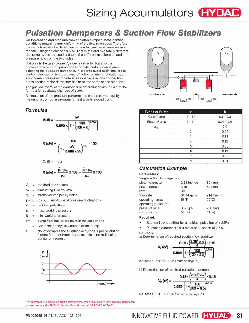
INNOVATIVE FLUID POWER 81PN#02068195 / 1.15 / ACU1102-1326
Pulsation Dampeners & Suction Flow Stabilizers
Types of Pump z k
Gear Pump 7 - 14 0.1 - 0.3
Piston Pump 1 - 11 0.01 - 0.6
e.g. 1 0.6
2 0.25
3 0.13
4 0.12
5 0.05
6 0.13
7 0.02
9 0.01
For assistance in sizing pulsation dampeners, shock absorbers, and suction stabilizers, please contact the HYDAC Accumulator Group at 1-877-GO HYDAC.
Calculation ExampleParameters:Single acting 3-plunger pumppiston diameter 2.36 inches (60 mm) piston stroke 3.15 (80 mm)rpm 370flow rate 64.44 gpm (244 l/min.) operating temp. 68°F (20°C) operating pressurepressure side 3625 psi (250 bar)suction side 58 psi (4 bar)
Required:
• Suction flow stabilizer for a residual pulsation of ± 2.5%
• Pulsation dampener for a residual pulsation of 0.5%
Solution: a) Determination of required suction flow stabilizer
Selected: SB 330-4 (see table on page 13)
b) Determination of required pulsation dampener
Selected: SB 330 P-20 (see table on page 47)
Sizing Accumulators
∆
V0 = required gas volume
∆V = fluctuating fluid volume
q(l) = stroke volume per cylinder
p̂ - pm = p̆ - pm = amplitude of pressure fluctuations
X = residual pulsations
p̂ = max. working pressure
p̆ = min. working pressure
pm = pump flow rate or pressure in the suction line
= Coefficient of cyclic variation of the pump
z = No. of compressions / effective cylinders per revolution factors for other types, i.e. gear, axial, and radial piston pumps on request
∆V (l) = k q
On the suction and pressure side of piston pumps almost identical conditions regarding non-uniformity of the flow rate occur. Therefore the same formulas for determining the effective gas volume are used for calculating the dampener size. That in the end two totally different dampener types are used is due to the different acceleration and pressure ratios on the two sides.
Not only is the gas volume V0 a decisive factor but also the connection size of the pump has to be taken into account when selecting the pulsation dampener. In order to avoid additional cross section changes which represent reflection points for vibrations, and also to keep pressure drops to a reasonable level, the connection cross section of the dampener has to be the same as the pipe line.
The gas volume V0 of the dampener is determined with the aid of the formula for adiabatic changes of state.
A simulation of the pressure performance can be carried out by means of a computer program for real pipe line conditions.
Formulas

INNOVATIVE FLUID POWER82 PN#02068195 / 1.15 / ACU1102-1326
Name Title
Company E-mail
Address
Phone State Zip
Phone Fax
Sizing Accumulators
Operation of Pump Continuous Operation
Emergency Operation
Maximum Operating Pressure (P2) PSI
Minimum Operating Pressure (P1) PSI
Precharge Pressure at 68˚F (20˚C) (P0) PSI
Temperature Range of Environment (T) ˚F
Temperature Range of Fluid or System (TF) ˚F
Pump Flow Rate (QP) GPM
Total Cycle Time of System (TE) Sec.
Number of Actuators (cylinders, etc.) (NV)
Fluid
Energy Storage Form
Please attach any special requirements or drawings to the fax or e-mail.
Required Mounting Orientation
Additional Remarks
Country of Final Installation (for country codes please see page 3)
Required QuantityAnnual Usage Target Price Competitor Quantity
Actuator Time Schedule and Flow QVi = Required Actuator Flow (GPM) Ei = Actuator Start Time Ai = Actuator Shut Down Time (i = 1 for first actuator, i = 2 for second actuator, etc. up to NV)
QV1 = E1 = A1 =
QV2 = E2 = A2 =
QV3 = E3 = A3 =
QV4 = E4 = A4 =
QV5 = E5 = A5 =

INNOVATIVE FLUID POWER 83PN#02068195 / 1.15 / ACU1102-1326
Sizing Accumulators Sizing Accumulators
Name Title
Company E-mail
Address
Phone State Zip
Phone Fax
What is the source of the shock? (i.e. valve closing, pump start, or other - please describe)
Fluid
Shock Applications Form
Please attach any special requirements or drawings to the fax or e-mail.
Required Mounting Orientation
Additional Remarks
Country of Final Installation (for country codes please see page 3)
Required QuantityAnnual Usage Target Price Competitor Quantity
At the instance the shock occurs what is the... Flow rate: GPM
Normal Operating Pressure: PSI ; Maximum Spike Pressure: PSI
The system’s maximum allowable design pressure: PSI
Information is required on all piping from the shock source to the anticipated location of the shock absorber (accumulator). Please continue to answer the following:
Total Number of pipes: (up to 10 pipes)
Starting at the shock source, please answer the following: Inner
Length Inner
Length
Pipe Diameter (feet)
Pipe Diameter (feet)
(inches) (inches)
1 6
2 7
3 8
4 9
5 10
If the vertical height from the shock source to the anticipated location of the shock absorber is greater than 10 feet please state this distance.
Vertical Height: feet
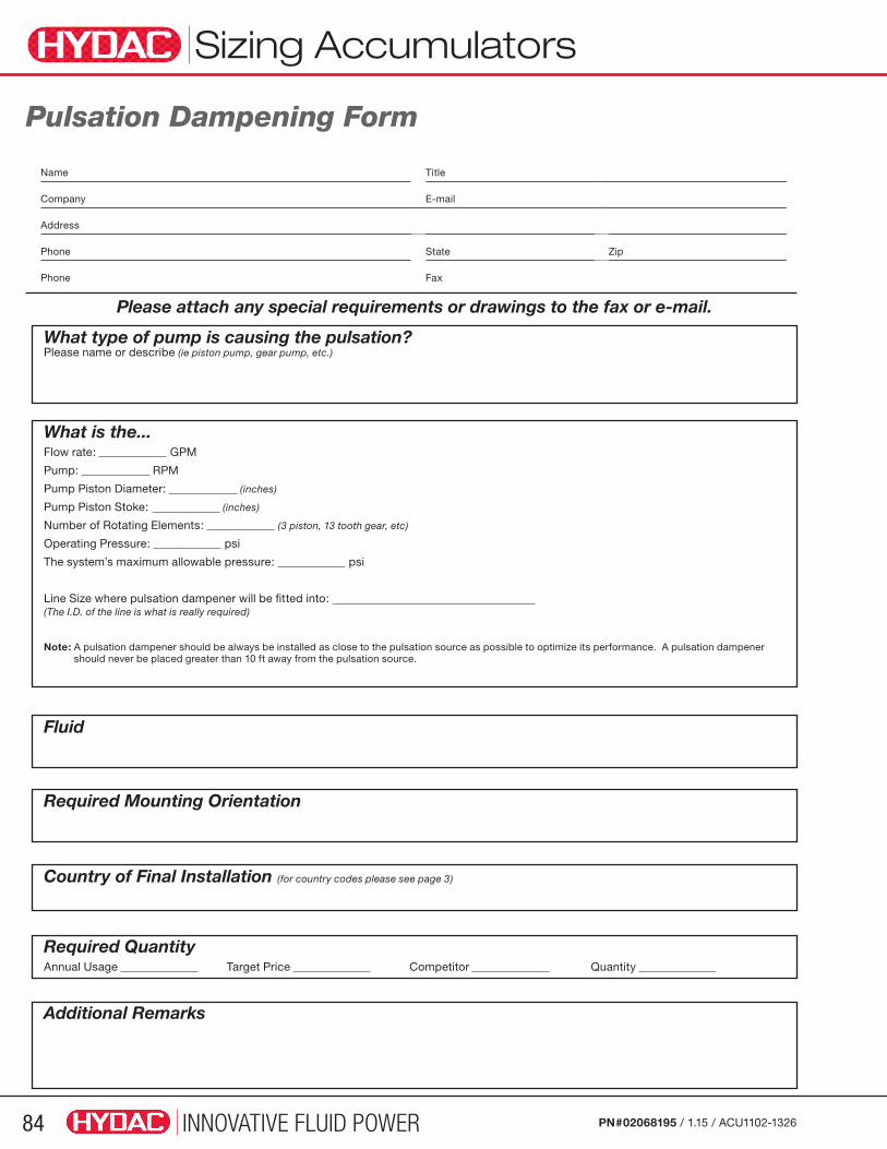
INNOVATIVE FLUID POWER84 PN#02068195 / 1.15 / ACU1102-1326
Sizing Accumulators
Name Title
Company E-mail
Address
Phone State Zip
Phone Fax
What type of pump is causing the pulsation? Please name or describe (ie piston pump, gear pump, etc.)
Fluid
Pulsation Dampening Form
Please attach any special requirements or drawings to the fax or e-mail.
Required Mounting Orientation
Additional Remarks
Country of Final Installation (for country codes please see page 3)
Required QuantityAnnual Usage Target Price Competitor Quantity
What is the... Flow rate: GPM
Pump: RPM
Pump Piston Diameter: (inches)
Pump Piston Stoke: (inches)
Number of Rotating Elements: (3 piston, 13 tooth gear, etc)
Operating Pressure: psi
The system’s maximum allowable pressure: psi
Line Size where pulsation dampener will be fitted into: (The I.D. of the line is what is really required)
Note: A pulsation dampener should be always be installed as close to the pulsation source as possible to optimize its performance. A pulsation dampener should never be placed greater than 10 ft away from the pulsation source.
HYD1303-1513
Global Presence. Local Expertise.HYDAC has become the first US manufacturer capable of producing bladder, piston and diaphragm accumulators in the United States. Our customers can have it all – superior engineering producing state-of-the-art products in record time. That’s customer service!
Industries and Applications for:• Offshore
• Oil and Gas
• Loading Station / Refineries
• Chemical Industry
• Agricultural & Forestry Machines
• Construction Machinery
• Cranes & Commercial Vehicles
• Rail Vehicles
• Automotive
• Machine Tools
• Plastics Technology
• Die Casting Machines
• Steel Industry
• Power Plants

Global HeadquartersHYDAC INTERNATIONAL
GMBH
IndustriegebietD – 66280 Sulzbach/Saar
Germany
Tel.: +49 6897 509-01
Fax: +49 6897 509-577
Internet: www.hydac.comEmail: [email protected]
North America Locations USA www.HYDACusa.com
HYDAC TECHNOLOGY CORPORATION Filter Division2260 City Line Road Bethlehem, PA 18017+1.610.266.0100
HYDAC TECHNOLOGY CORPORATION Cooling System Division1051 Airlie Parkway Denver, NC 28037+1.610.266.0100
HYDAC TECHNOLOGY CORPORATION Accessory Division Marketing2204 Avenue C Bethlehem, PA 18017+1.610.266.0100
HYDAC TECHNOLOGY CORPORATION Cooling System Division - Industrial Office445 Windy Point Drive Glendale Heights, IL 60139+1.630.545.0800
HYDAC TECHNOLOGY CORPORATION Electronic Division Process Filter DivisionHYDAC CORPORATION Accumulator Division90 Southland Drive Bethlehem, PA 18017+1.610.266.0100
HYDAC TECHNOLOGY CORPORATION HYDAC CORPORATION Sales Office & Operations1718 Fry Road, Suite 100 Houston, TX 77084+1.281.579.8100
HYDAC TECHNOLOGY CORPORATION Filter System Division Process Filter Division580 West Park Road Leetsdale, PA 15056+1.724.318.1100
HYDAC TECHNOLOGY CORPORATION HYDAC CORPORATION NE Sales Office1660 Enterprise Parkway • Suite E Wooster, OH 44691+1.610.266.0100
HYDAC TECHNOLOGY CORPORATION Hydraulic Division - Compact Hydraulics450 Windy Point Drive Glendale Heights, IL 60139+1.630.545.0800
HYDAC TECHNOLOGY CORPORATION HYDAC CORPORATION SE Sales Office1051 Airlie Parkway Denver, NC 28037+1.610.266.0100
HYDAC TECHNOLOGY CORPORATION Mobile Hydraulic Division1660 Enterprise Parkway • Suite E Wooster, OH 44691+1.610.266.0100
HYDAC TECHNOLOGY CORPORATION HYDAC CORPORATION NW Sales Office1201 NE 144th St. Bldg. B, Suite 111 Vancouver, WA 98685+1.610.266.0100
HYDAC CYLINDERS LLC540 Carson Road North Birmingham, AL 35217+1.205.520.1220
Canada www.HYDAC.ca
HYDAC CORPORATION14 Federal Road Welland, Ontario, Canada L3B 3P2 +1.905.714.9322
HYDAC CORPORATION Sales Office101 - 18207 114 AVE W Edmonton, Alberta, Canada T5S 2P6+1.780.484.4228
HYDAC CORPORATION Sales OfficeMontreal, Québec, Canada J2M 1K9+1.877.539.3388
Mexico www.HYDACmex.com
HYDAC INTERNATIONAL SA de CVCalle Alfredo A Nobel #35 Col Puente de Vigas Tlalnepantla, Edo Mexico CP. 54075+011.52.55.4777.1262
PN#02068195 / 1.15 / ACU1102-1326© Copyright 2015 HYDAC TECHNOLOGY CORPORATION • Accumulator Catalog