accurate depth map estimation from a lenslet light field ... · estimation of the stereo...
TRANSCRIPT
Accurate Depth Map Estimation from a Lenslet Light Field Camera
Hae-Gon Jeon Jaesik Park Gyeongmin Choe Jinsun ParkYunsu Bok Yu-Wing Tai In So Kweon
Korea Advanced Institute of Science and Technology (KAIST), Republic of Korea[hgjeon,jspark,gmchoe,ysbok]@rcv.kaist.ac.kr
[zzangjinsun,yuwing]@gmail.com, [email protected]
Abstract
This paper introduces an algorithm that accurately esti-mates depth maps using a lenslet light field camera. Theproposed algorithm estimates the multi-view stereo cor-respondences with sub-pixel accuracy using the cost vol-ume. The foundation for constructing accurate costs isthreefold. First, the sub-aperture images are displaced us-ing the phase shift theorem. Second, the gradient costsare adaptively aggregated using the angular coordinates ofthe light field. Third, the feature correspondences betweenthe sub-aperture images are used as additional constraints.With the cost volume, the multi-label optimization propa-gates and corrects the depth map in the weak texture re-gions. Finally, the local depth map is iteratively refinedthrough fitting the local quadratic function to estimate anon-discrete depth map. Because micro-lens images con-tain unexpected distortions, a method is also proposed thatcorrects this error. The effectiveness of the proposed algo-rithm is demonstrated through challenging real world ex-amples and including comparisons with the performance ofadvanced depth estimation algorithms.
1. IntroductionThe problem of estimating an accurate depth map
from a lenslet light field camera, e.g. LytroTM [1] andRaytrixTM [19], is investigated. Different to conventionalcameras, a light field camera captures not only a 2D image,but also the directions of the incoming light rays. The addi-tional light directions allow the image to be re-focused andthe depth map of a scene to be estimated as demonstratedin [12, 17, 19, 23, 26, 29].
Because the baseline between sub-aperture images froma lenslet light field camera is very narrow, directly applyingthe existing stereo matching algorithms such as [20] can-not produce satisfying results, even if the applied algorithmis a top ranked method in the Middlebury stereo matchingbenchmark. As reported in Yu et al. [29], the disparity range
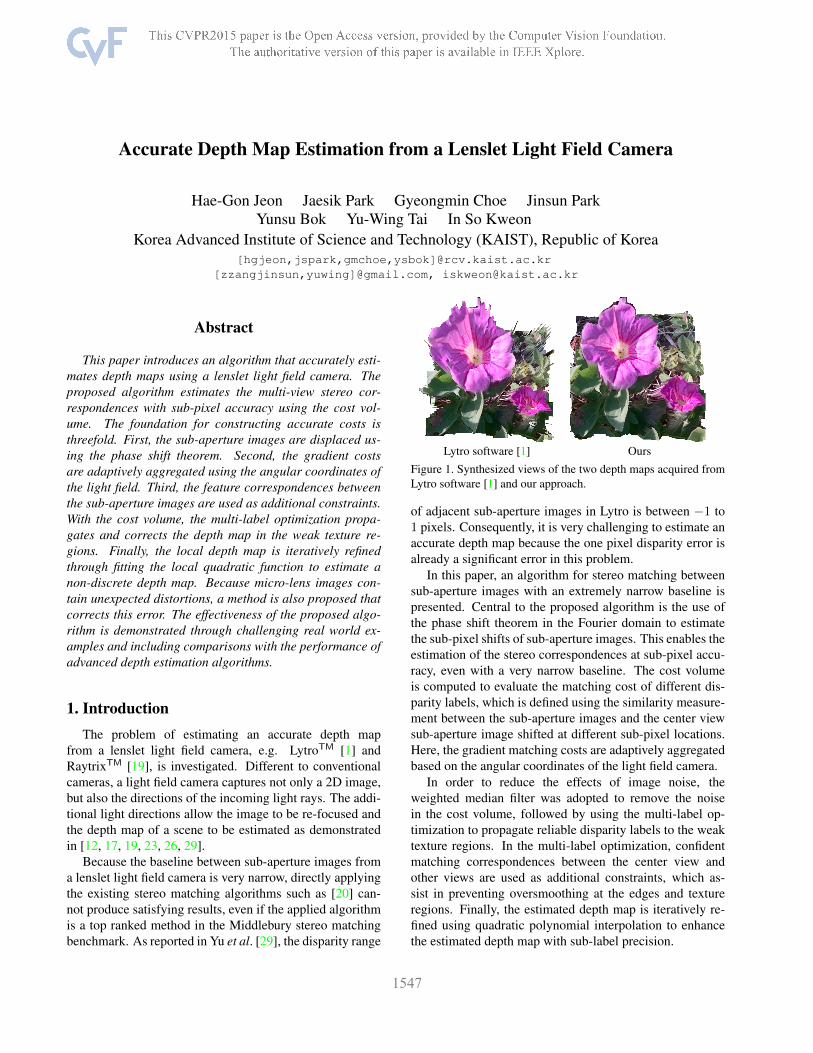
Lytro software [1] Ours
Figure 1. Synthesized views of the two depth maps acquired fromLytro software [1] and our approach.
of adjacent sub-aperture images in Lytro is between −1 to1 pixels. Consequently, it is very challenging to estimate anaccurate depth map because the one pixel disparity error isalready a significant error in this problem.
In this paper, an algorithm for stereo matching betweensub-aperture images with an extremely narrow baseline ispresented. Central to the proposed algorithm is the use ofthe phase shift theorem in the Fourier domain to estimatethe sub-pixel shifts of sub-aperture images. This enables theestimation of the stereo correspondences at sub-pixel accu-racy, even with a very narrow baseline. The cost volumeis computed to evaluate the matching cost of different dis-parity labels, which is defined using the similarity measure-ment between the sub-aperture images and the center viewsub-aperture image shifted at different sub-pixel locations.Here, the gradient matching costs are adaptively aggregatedbased on the angular coordinates of the light field camera.
In order to reduce the effects of image noise, theweighted median filter was adopted to remove the noisein the cost volume, followed by using the multi-label op-timization to propagate reliable disparity labels to the weaktexture regions. In the multi-label optimization, confidentmatching correspondences between the center view andother views are used as additional constraints, which as-sist in preventing oversmoothing at the edges and textureregions. Finally, the estimated depth map is iteratively re-fined using quadratic polynomial interpolation to enhancethe estimated depth map with sub-label precision.
1
In the experiments, it was found that a micro-lens im-age of lenslet light field cameras contains depth distor-tions. Therefore, a method of correcting this error is alsopresented. The effectiveness of the proposed algorithm isdemonstrated using challenging real world examples thatwere captured by a Lytro camera, a Raytrix camera, and alab-made lenslet light field camera. A performance compar-ison with advanced methods is also presented. An exampleof the results of the proposed method are presented in Fig. 1.
2. Related Work
Previous work related to depth map (or disparity map1)estimation from a light field image is reviewed. Comparedwith conventional approaches in stereo matching, lensletlight field images have very narrow baselines. Conse-quently, approaches based on correspondence matching donot typically work well because the sub-pixel shift in thespatial domain usually involves interpolation with blurri-ness, and the matching costs of stereo correspondence arehighly ambiguous. Therefore, instead of using correspon-dence matching, other cues and constraints were used to es-timate the depth maps from a lenslet light field image.
Georgiev and Lumsdaine [7] computed a normalizedcross correlation between microlens images in order to es-timate the disparity map. Bishop and Favaro [4] introducedan iterative method for a multi-view stereo image for a lightfield. Wanner and Goldluecke [26] used a structure tensorto compute the vertical and horizontal slopes in the epipolarplane of a light field image, and they formulated the depthmap estimation problem as a global optimization approachthat was subject to the epipolar constraint. Yu et al. [29]analyzed the 3D geometry of lines in a light field imageand computed the disparity maps through line matching be-tween the sub-aperture images. Tao et al. [23] introduceda fusion method that uses the correspondences and defocuscues of a light field image to estimate the disparity maps.After the initial estimation, a multi-label optimization is ap-plied in order to refine the estimated disparity map. Heberand Pock [8] estimated disparity maps using the low-rankstructure regularization to align the sub-aperture images.
In addition to the aforementioned approaches, there havebeen recent studies that have estimated depth maps fromlight field images. For example, Kim et al. [10] estimateddepth maps from a DSLR camera with movement, whichsimulated the multiple viewpoints of a light field image.Chen et al. [6] introduced a bilateral consistency metric onthe surface camera in order to estimate the stereo correspon-dence in a light field image in the presence of occlusion.However, it should be noted that the baseline of the lightfield images presented in Kim et al. [10] and Chen et al. [6]are significantly larger than the baseline of the light field
1We sometimes use disparity map to represent depth map.
images captured using a lenslet light field camera.Compared with previous studies, the proposed algorithm
computes the cost volume that is based on sub-pixel multi-view stereo matching. Unique in the proposed algorithmis the usage of the phase shift theorem when performingthe sub-pixel shifts of sub-aperture image. The phase shifttheorem allows the reconstruction of the sub-pixel shiftedsub-aperture images without introducing blurriness in con-trast to spatial domain interpolation. As is demonstrated inthe experiments, the proposed algorithm is highly effectiveand outperforms the advanced algorithms in depth map es-timation using a lenslet light field image.
3. Sub-aperture Image AnalysisFirst, the characteristics of sub-aperture images obtained
from a lenslet-based light field camera are analyzed, andthen the proposed distortion correction method is described.
3.1. Narrow Baseline Sub-aperture Image
Narrow baseline. According to the lenslet light field cam-era projection model proposed by Bok et al. [5], the view-point (S, T ) of a sub-aperture image with an angular direc-tion s = (s, t)2 is as follows:[
ST
]=D
d(D + d)
[s/fxt/fy
], (1)
where D is the distance between the lenslet array and thecenter of main lens, d is the distance between the lensletarray and imaging sensor, and f is the focal length of themain lens. With the assumption of a uniform focal length(i.e. fx = fy = f ), the baseline between two adjacent sub-aperture images is defined as baseline := (D+d)D
df .Based on this, we need to shorten f , shorten d, or
lengthen D for a wider baseline. However, f cannot be tooshort because it is proportional to the angular resolution ofthe micro-lenses in a lenslet array. Therefore, the maximumbaseline that is multiplication of the baseline and angularresolution of sub-aperture images remains unchanged evenif the value of f varies. If the physical size of the micro-lenses is too large, the spatial resolution of the sub-apertureimages is reduced. Shortening d enlarges the angular dif-ference between the corresponding rays of adjacent pixelsand might cause radial distortion of the micro-lenses. Fi-nally, lengthening D increases the baseline, but the fieldof view is reduced. Due to these challenges, the disparityrange of sub-aperture images is quite narrow. For example,the disparity range between adjacent sub-aperture views ofthe Lytro camera is smaller than ±1 pixel [29].
2The 4D parameterization [7, 17, 26] is followed where the pixel co-ordinates of a light field image I are defined using the 4D parameters of(s, t, x, y). Here, s = (s, t) denotes the discrete index of the angular di-rections and x = (x, y) denotes the Cartesian image coordinates of eachsub-aperture image.
(a) Before compensation
(b) After compensation
Pivot
Rotate
(c) EPI compensation (d) EPI difference
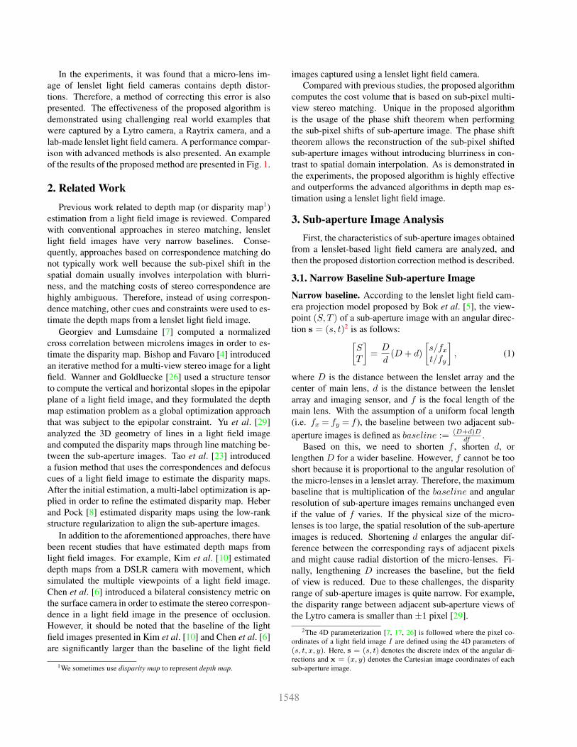
Figure 2. (a) and (b) EPI before and after distortion correction.(c) shows our compensation process for a pixel. (d) shows slopedifference between two EPIs.
without correction with correction
Figure 3. Disparity map before and after distortion correction(Sec. 3.2). Real-world planar scene is captured and the depth mapis computed using our approach (Sec. 4).
Sub-aperture image distortion. From the analyses con-ducted in this study, it is observed that the lenslet light fieldimages contain optical distortions that are caused by boththe main lens (thin lens model) and micro-lenses (pinholemodel). Although the radial distortion of the main lens canbe calibrated using conventional methods, it is imperfect,particularly for light rays that have large angular differencesfrom the optical axis. The distortion caused by these raysis called astigmatism [22]. Moreover, because the conven-tional distortion model is based on a pinhole camera model,the rays that do not pass through the center of the main lenscannot fit well to the model. The distortion caused by thoserays is called field curvature [22]. Because they are the pri-mary causes of the depth distortion, the two distortions arecompensated in the following subsection.
3.2. Distortion Estimation and Correction
During the capture of a light field image of a planar ob-ject, spatially variant epipolar plane image (EPI) slopes (i.e.non-uniform depths) are observed that result from the dis-tortions mentioned in Sec. 3.1 (see Fig. 3). In addition, thedegree of distortion also varies for each sub-aperture image.
To solve this problem, an energy minimization problemis formulated under a constant depth assumption as follows:
G = argminG
∑x
|θ(I(x))− θo −G(x)| (2)
where | · | denotes the absolute operator. θo, θ(·), and G(·)denote the slope without distortion, the slope of EPI, andthe amount of distortion at point x, respectively.
The amount of field curvature distortion is estimated for
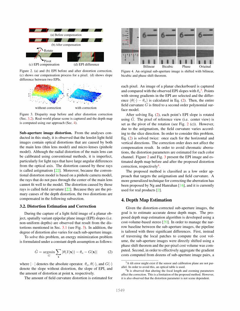
Bilinear Bicubic Phase Original
Figure 4. An original sub-aperture image is shifted with bilinear,bicubic and phase shift theorem.
each pixel. An image of a planar checkerboard is capturedand compared with the observed EPI slopes with θo3. Pointswith strong gradients in the EPI are selected and the differ-ence (θ(·) − θo) is calculated in Eq. (2). Then, the entirefield curvature G is fitted to a second order polynomial sur-face model.
After solving Eq. (2), each point’s EPI slope is rotatedusing G. The pixel of reference view (i.e. center view) isset as the pivot of the rotation (see Fig. 2 (c)). However,due to the astigmatism, the field curvature varies accord-ing to the slice direction. In order to consider this problem,Eq. (2) is solved twice: once each for the horizontal andvertical directions. The correction order does not affect thecompensation result. In order to avoid chromatic aberra-tions, the distortion parameters are estimated for each colorchannel. Figure 2 and Fig. 3 present the EPI image and es-timated depth map before and after the proposed distortioncorrection, respectively4.
The proposed method is classified as a low order ap-proach that targets the astigmatism and field curvature. Amore generalized technique for correcting the aberration hasbeen proposed by Ng and Hanrahan [16], and it is currentlyused for real products [2].
4. Depth Map Estimation
Given the distortion-corrected sub-aperture images, thegoal is to estimate accurate dense depth maps. The pro-posed depth map estimation algorithm is developed using acost-volume-based stereo [20]. In order to manage the nar-row baseline between the sub-aperture images, the pipelineis tailored with three significant differences. First, insteadof traversing the local patches to compute the cost vol-ume, the sub-aperture images were directly shifted using aphase shift theorem and the per-pixel cost volume was com-puted. Second, in order to effectively aggregate the gradientcosts computed from dozens of sub-aperture image pairs, a
3A tilt error might exist if the sensor and calibration plane are not par-allel. In order to avoid this, an optical table is used.
4It is observed that altering the focal length and zooming parametersaffect the correction. This is a limitation of the proposed method. However,it is also observed that the distortion parameter is not scene dependent.
weight term that considers the horizontal/vertical deviationin the st coordinates between the sub-aperture image pairsis defined. Third, because small viewpoint changes of sub-aperture images allow feature matching to be more reliable,a guidance of confident matching correspondences is alsoincluded in the discrete label optimization [11]. The detailsare described in following sub-sections.
4.1. Phase Shift based Sub-pixel Displacement
A key contribution of the proposed depth estimation al-gorithm is matching the narrow baseline sub-aperture im-ages using sub-pixel displacements. According to the phaseshift theorem, if an image I is shifted by ∆x ∈ R2, thecorresponding phase shift in the 2D Fourier transform is:
F{I(x + ∆x)} = F{I(x)}exp2πi∆x, (3)
where F{·} denotes the discrete 2D Fourier transform.In Eq. (3), multiplying the exponential term in the frequencydomain is the same as convolving a Dirichlet kernel (or peri-odic sinc) in the spatial domain. According to the Nyquist-Shannon sampling theorem [21], a continuous band-limitedsignal can be perfectly reconstructed through convolving itwith a sinc function. If the centroid of the sinc functionis deviated from the origin, precisely shifted signals can beobtained. In the same manner, Eq. (3) generates a preciselyshifted image in the spatial domain if the sub-aperture im-age is band-limited. Therefore, the sub-pixel shifted imageI ′(x) is obtained using:
I ′(x) = I(x + ∆x) = F−1{F{I(x)}exp2πi∆x}. (4)
In practice, the light field image is not always a band-limited signal. This results from the weak pre-filteringthat fits the light field into the sub-aperture image resolu-tion [13, 24]. However, the artifact is not obvious for re-gions where the texture is obtained from the source surfacein the scene. For example, a sub-aperture image of a reso-lution chart captured by Lytro camera is presented in Fig. 4.This image is shifted by ∆x = [2.2345,−1.5938] pixels.Compared with the displacement that results from the bilin-ear and bicubic interpolations, the sub-pixel shifted imageusing the phase shift theorem is sharper and does not con-tain blurriness. Note that having an accurate reconstructionof sub-pixel shifted images is significant for accurate depthmap estimations, particularly when the baseline is narrow.The effect of the interpolation method and depth accuracyis analyzed in Sec. 5.
In this implementation, the fast Fourier transform witha circular boundary condition is used to manage the non-infinite signals. Because the proposed algorithm shifts theentire sub-aperture image instead of local patches, the ar-tifacts that result from periodicity problems only appear atthe boundary of the image within a width of a few pixels(less than two pixels), which is negligible.
4.2. Building the Cost Volume
In order to match sub-aperture images, two complemen-tary costs were used: the sum of absolute differences (SAD)and the sum of gradient differences (GRAD). The cost vol-ume C is defined as a function of x and cost label l:
C(x, l) = αCA(x, l) + (1−α)CG(x, l), (5)
where α ∈ [0, 1] adjusts the relative importance betweenthe SAD cost CA and GRAD cost CG. CA is defined as
CA(x, l)=∑s∈V
∑x∈Rx
min(|I(sc,x)−I(s,x+∆x(s, l))|, τ1),
(6)where Rx is a small rectangular region centered at x; τ1 isa truncation value of a robust function; and V contains thest coordinate pixels s, except for the center view sc. Equa-tion (3) is used for precise sub-pixel shifting of the images.Equation (6) builds a matching cost through comparingthe center sub-aperture image I(sc,x) with the other sub-aperture images I(s,x) to generate a disparity map from acanonical viewpoint. The 2D shift vector ∆x in Eq. (6) isdefined as follows:
∆x(s, l) = lk(s− sc), (7)
where k is the unit of the label in pixels. ∆x linearly in-creases as the angular deviations from the center viewpointincrease. Another cost volume CG is defined as follows:
CG(x, l)=∑s∈V
∑x∈Rx
β(s) min(Diffx(sc, s,x, l), τ2
)(8)
+(1− β(s)
)min
(Diffy(sc, s,x, l), τ2
)where Diffx(sc, s,x, l) = |Ix(sc,x)− Ix(s,x+ ∆x(s, l))|denotes the differences between the x-directional gradientof the sub-aperture images. Diffy is defined similarly onthe y-directional gradients. τ2 is a truncation constant thatsuppresses outliers. β(s) in Eq. (8) controls the relative im-portance of the two directional gradient differences basedon the relative st coordinates. β(s) is defined as follows:
β(s) =|s− sc|
|s− sc|+ |t− tc|. (9)
According to Eq. (9), β increases if the target view s islocated at the horizontal extent of the center view sc. Inthis case, only the gradient costs in the x direction are ag-gregated to CG. Note that β is independent of the scenebecause it is determined purely using the relative positionbetween s and sc.
As a sequential step, every cost slice is refined using anedge-preserving filter [15] to alleviate the coarsely scatteredunreliable matches. Here, the central sub-aperture image isused to determine the weights used for the filter. They are
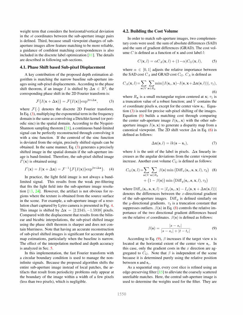
(a) (b) (c) (d) (e)
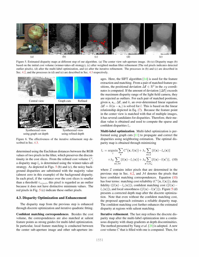
Figure 5. Estimated disparity maps at different step of our algorithm. (a) The center view sub-aperture image. (b)-(e) Disparity maps (b)based on the initial cost volume (winner-takes-all strategy), (c) after weighted median filter refinement (The red pixels indicates detectedoutlier pixels), (d) after the multi-label optimization, and (e) after the iterative refinement. The processes in (b) and (c) are described inSec. 4.2, and the processes in (d) and (e) are described in Sec. 4.3 respectively.
Central view Graph cuts Refined
Synthesized view
using graph cut depth
Synthesized view
using refined depth
Figure 6. The effectiveness of the iterative refinement step de-scribed in Sec. 4.3.
determined using the Euclidean distances between the RGBvalues of two pixels in the filter, which preserves the discon-tinuity in the cost slices. From the refined cost volume C ′,a disparity map la is determined using the winner-takes-allstrategy. As depicted in Figs. 5 (b) and (c), the noisy back-ground disparities are substituted with the majority value(almost zero in this example) of the background disparity.In each pixel, if the variance over the cost slices is smallerthan a threshold τreject, this pixel is regarded as an outlierbecause it does not have distinctive minimum values. Thered pixels in Fig. 5 (c) indicate these outlier pixels.
4.3. Disparity Optimization and Enhancement
The disparity map from the previous step is enhancedthrough discrete optimization and iterative quadratic fitting.
Confident matching correspondences. Besides the costvolume, the correspondences are also matched at salientfeature points as strong guides for multi-label optimization.In particular, local feature matching is conducted betweenthe center sub-aperture image and other sub-aperture im-
ages. Here, the SIFT algorithm [14] is used for the featureextraction and matching. From a pair of matched feature po-sitions, the positional deviation ∆f ∈ R2 in the xy coordi-nates is computed. If the amount of deviation ‖∆f‖ exceedsthe maximum disparity range of the light field camera, theyare rejected as outliers. For each pair of matched positions,given s, sc, ∆f , and k, an over-determined linear equation∆f = lk(s− sc) is solved for l. This is based on the linearrelationship depicted in Eq. (7). Because the feature pointin the center view is matched with that of multiple images,it has several candidates for disparities. Therefore, their me-dian value is obtained and used to compute the sparse andconfident disparities lc.
Multi-label optimization. Multi-label optimization is per-formed using graph cuts [11] to propagate and correct thedisparities using neighboring estimation. The optimal dis-parity map is obtained through minimizing
lr = argminl
∑x
C ′(x, l(x)
)+ λ1
∑x∈I‖l(x)−la(x)‖
+λ2
∑x∈M‖l(x)−lc(x)‖+ λ3
∑x′∈Nx
‖l(x)−l(x′)‖, (10)
where I contains inlier pixels that are determined in theprevious step in Sec. 4.2, and M denotes the pixels thathave confident matching correspondences. Equation (10)has four terms: matching cost reliability (C ′
(x, l(x)
)), data
fidelity (‖l(x)− la(x)‖), confident matching cost (‖l(x)−lc(x)‖), and local smoothness (‖l(x)−l(x′)‖). Figure 5 (d)presents a corrected depth map after the discrete optimiza-tion. Note that even without the confident matching cost,the proposed approach estimates a reliable disparity map.The confident matching cost further enhances the estimateddisparity at regions with salient matching.
Iterative refinement. The last step refines the discrete dis-parity map after the multi-label optimization into a contin-uous disparity with sharp gradients at depth discontinuities.The method presented by Yang et al. [28] is adopted. A newcost volume C that is filled with one is computed. Then, for
0.2 %
1 %
GT Bilinear Bicubic Ours w/o IterRefine OursGCDL
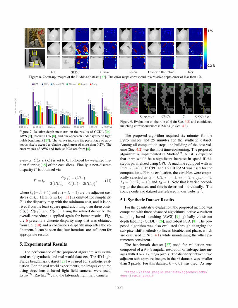
Figure 8. Zoom-up images of the Buddha2 dataset [27]. The error maps correspond to a relative depth error of less than 1%.
Buddha Buddha2 Mona Papillon Still life Horses Medieval
GCDL 7.28 26.55 15.08 7.13 4.51 16.44 21.76
AWS 8.37 15.05 12.9 8.79 6.33 16.83 11.09
Robust PCA 5.03 11.52 12.75 8 4.2 11.78 11.09
Bilinear 5.37 16.2 11.3 7.38 2.89 11.18 9.03
Bicubic 5.33 15.35 9.02 7.4 2.35 6.65 8.73
Ours 4.69 9.88 8.91 6.06 2.27 6.22 6.38
LAGC 18.76 41.26 27.67 23.32 17.16 47.1 42.39
Only Matching 6.64 17.58 18.91 26.16 3.19 11.42 24.94
Ours w/o IterRefine 5.26 12.48 11.26 11.31 3.38 7.59 6.52
7.28
26.55
15.08
7.13
4.51
16.44
21.76
8.37
15.05
12.9
8.79
6.33
16.83
11.09
5.03
11.52
12.75
8
4.2
11.78
11.09
5.37
16.2
11.3
7.38
2.89
11.18
9.03
5.33
15.35
9.02
7.4
2.35
6.65 8.73
4.69
9.88
8.91
6.06
2.27
6.22
6.38
BUDDHA BUDDHA2 MONA PAPILLON STILL LIFE HORSES MEDIEVAL
ERROR PER
CEN
T (%
)
GCDL AWS Robust PCA Bilinear Bicubic Ours
Figure 7. Relative depth measures on the results of GCDL [26],AWS [9], Robust PCA [8], and our approach under synthetic lightfields benchmark [27]. The values indicate the percentage of erro-neous pixels exceed a relative depth error of more than 0.2%. Theerror values of AWS and Robust PCA are from [8].
every x, C(x, lr(x)) is set to 0, followed by weighted me-dian filtering [15] of the cost slices. Finally, a non-discretedisparity l∗ is obtained via
l∗ = lr −C(l+)− C(l−)
2(C(l+) + C(l−)− 2C(lr)
) , (11)
where l+(= lr + 1) and l−(= lr − 1) are the adjacent costslices of lr. Here, x in Eq. (11) is omitted for simplicity.l∗ is the disparity map with the minimum cost, and it is de-rived from the least square quadratic fitting over three costs:C(lr), C(l+), and C(l−). Using the refined disparity, theoverall procedure is applied again for better results. Fig-ure 6 presents a discrete disparity map that was obtainedfrom Eq. (10) and a continuous disparity map after the re-finement. It can be seen that four iterations are sufficient forappropriate results.
5. Experimental Results
The performance of the proposed algorithm was evalu-ated using synthetic and real world datasets. The 4D LightFields benchmark dataset [27] was used for synthetic eval-uation. For the real world experiments, the images capturedusing three lenslet based light field cameras were used:LytroTM, RaytrixTM, and the lab-made light field camera.
CMCs 𝛽Graph-cuts CMCs + 𝛽
Figure 9. Evaluation on the role of β (in Sec. 4.2) and confidencematching correspondences (CMCs) (in Sec. 4.3).
The proposed algorithm required six minutes for theLytro images and 25 minutes for the synthetic dataset.Among all computation steps, the building of the cost vol-ume (Sec. 4.2) was the most time-consuming. The proposedalgorithm is implemented in MatlabTM, but it is expectedthat there would be a significant increase in speed if thisstep is parallelized using GPU. A machine equipped with anIntel i7 3.40 GHz CPU and 16 GB RAM was used for thecomputations. For the evaluation, the variables were empir-ically selected as α = 0.3, τ1 = 1, τ2 = 3, τreject = 5,λ1 = 0.5, λ2 = 10, and λ3 = 1. Note that k varied accord-ing to the dataset, and this is described individually. Thesource code and dataset are released in our website 5.
5.1. Synthetic Dataset Results
For the quantitative evaluation, the proposed method wascompared with three advanced algorithms: active wavefrontsampling based matching (AWS) [9], globally consistentdepth labeling (GCDL) [26], and robust PCA [8]. The pro-posed algorithm was also evaluated through changing thesub-pixel shift methods (bilinear, bicubic, and phase, whichare discussed in Sec. 4.1) while maintaining the other pa-rameters consistent.
The benchmark dataset [27] used for validation wascomposed of a 9× 9 angular resolution of sub-aperture im-ages with 0.5∼0.7 mega pixels. The disparity between twoadjacent sub-aperture images in the st domain was smallerthan 3 pixels. For this dataset, k= 0.03 was used. As sug-
5https://sites.google.com/site/hgjeoncv/home/depthfromlf_cvpr15
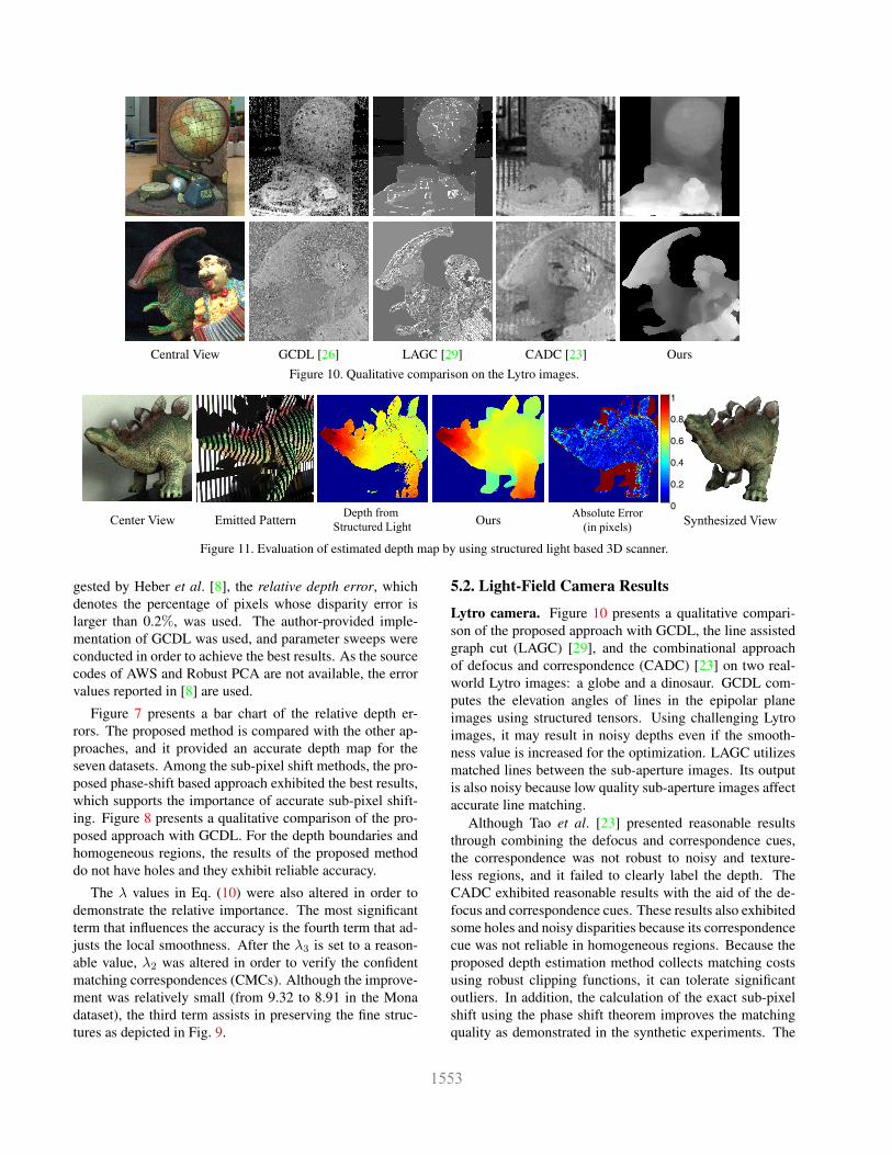
Central View GCDL [26] LAGC [29] CADC [23] Ours
Figure 10. Qualitative comparison on the Lytro images.
Center View Synthesized View
0
0.2
0.4
0.6
0.8
1
Depth from
Structured LightOurs
Absolute Error
(in pixels)Emitted Pattern
Figure 11. Evaluation of estimated depth map by using structured light based 3D scanner.
gested by Heber et al. [8], the relative depth error, whichdenotes the percentage of pixels whose disparity error islarger than 0.2%, was used. The author-provided imple-mentation of GCDL was used, and parameter sweeps wereconducted in order to achieve the best results. As the sourcecodes of AWS and Robust PCA are not available, the errorvalues reported in [8] are used.
Figure 7 presents a bar chart of the relative depth er-rors. The proposed method is compared with the other ap-proaches, and it provided an accurate depth map for theseven datasets. Among the sub-pixel shift methods, the pro-posed phase-shift based approach exhibited the best results,which supports the importance of accurate sub-pixel shift-ing. Figure 8 presents a qualitative comparison of the pro-posed approach with GCDL. For the depth boundaries andhomogeneous regions, the results of the proposed methoddo not have holes and they exhibit reliable accuracy.
The λ values in Eq. (10) were also altered in order todemonstrate the relative importance. The most significantterm that influences the accuracy is the fourth term that ad-justs the local smoothness. After the λ3 is set to a reason-able value, λ2 was altered in order to verify the confidentmatching correspondences (CMCs). Although the improve-ment was relatively small (from 9.32 to 8.91 in the Monadataset), the third term assists in preserving the fine struc-tures as depicted in Fig. 9.
5.2. Light-Field Camera Results
Lytro camera. Figure 10 presents a qualitative compari-son of the proposed approach with GCDL, the line assistedgraph cut (LAGC) [29], and the combinational approachof defocus and correspondence (CADC) [23] on two real-world Lytro images: a globe and a dinosaur. GCDL com-putes the elevation angles of lines in the epipolar planeimages using structured tensors. Using challenging Lytroimages, it may result in noisy depths even if the smooth-ness value is increased for the optimization. LAGC utilizesmatched lines between the sub-aperture images. Its outputis also noisy because low quality sub-aperture images affectaccurate line matching.
Although Tao et al. [23] presented reasonable resultsthrough combining the defocus and correspondence cues,the correspondence was not robust to noisy and texture-less regions, and it failed to clearly label the depth. TheCADC exhibited reasonable results with the aid of the de-focus and correspondence cues. These results also exhibitedsome holes and noisy disparities because its correspondencecue was not reliable in homogeneous regions. Because theproposed depth estimation method collects matching costsusing robust clipping functions, it can tolerate significantoutliers. In addition, the calculation of the exact sub-pixelshift using the phase shift theorem improves the matchingquality as demonstrated in the synthetic experiments. The
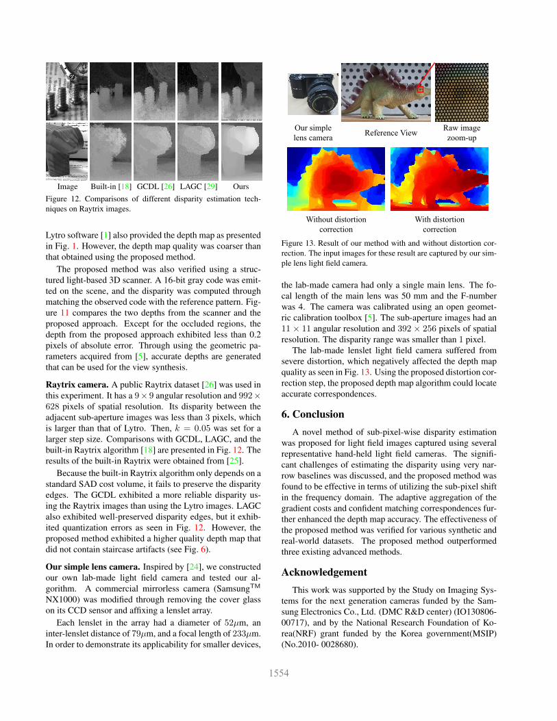
Image Built-in [18] GCDL [26] LAGC [29] Ours
Figure 12. Comparisons of different disparity estimation tech-niques on Raytrix images.
Lytro software [1] also provided the depth map as presentedin Fig. 1. However, the depth map quality was coarser thanthat obtained using the proposed method.
The proposed method was also verified using a struc-tured light-based 3D scanner. A 16-bit gray code was emit-ted on the scene, and the disparity was computed throughmatching the observed code with the reference pattern. Fig-ure 11 compares the two depths from the scanner and theproposed approach. Except for the occluded regions, thedepth from the proposed approach exhibited less than 0.2pixels of absolute error. Through using the geometric pa-rameters acquired from [5], accurate depths are generatedthat can be used for the view synthesis.
Raytrix camera. A public Raytrix dataset [26] was used inthis experiment. It has a 9× 9 angular resolution and 992×628 pixels of spatial resolution. Its disparity between theadjacent sub-aperture images was less than 3 pixels, whichis larger than that of Lytro. Then, k = 0.05 was set for alarger step size. Comparisons with GCDL, LAGC, and thebuilt-in Raytrix algorithm [18] are presented in Fig. 12. Theresults of the built-in Raytrix were obtained from [25].
Because the built-in Raytrix algorithm only depends on astandard SAD cost volume, it fails to preserve the disparityedges. The GCDL exhibited a more reliable disparity us-ing the Raytrix images than using the Lytro images. LAGCalso exhibited well-preserved disparity edges, but it exhib-ited quantization errors as seen in Fig. 12. However, theproposed method exhibited a higher quality depth map thatdid not contain staircase artifacts (see Fig. 6).
Our simple lens camera. Inspired by [24], we constructedour own lab-made light field camera and tested our al-gorithm. A commercial mirrorless camera (SamsungTM
NX1000) was modified through removing the cover glasson its CCD sensor and affixing a lenslet array.
Each lenslet in the array had a diameter of 52µm, aninter-lenslet distance of 79µm, and a focal length of 233µm.In order to demonstrate its applicability for smaller devices,
Our simple
lens cameraReference View
Raw image
zoom-up
Without distortion
correction
With distortion
correction
Figure 13. Result of our method with and without distortion cor-rection. The input images for these result are captured by our sim-ple lens light field camera.
the lab-made camera had only a single main lens. The fo-cal length of the main lens was 50 mm and the F-numberwas 4. The camera was calibrated using an open geomet-ric calibration toolbox [5]. The sub-aperture images had an11 × 11 angular resolution and 392 × 256 pixels of spatialresolution. The disparity range was smaller than 1 pixel.
The lab-made lenslet light field camera suffered fromsevere distortion, which negatively affected the depth mapquality as seen in Fig. 13. Using the proposed distortion cor-rection step, the proposed depth map algorithm could locateaccurate correspondences.
6. ConclusionA novel method of sub-pixel-wise disparity estimation
was proposed for light field images captured using severalrepresentative hand-held light field cameras. The signifi-cant challenges of estimating the disparity using very nar-row baselines was discussed, and the proposed method wasfound to be effective in terms of utilizing the sub-pixel shiftin the frequency domain. The adaptive aggregation of thegradient costs and confident matching correspondences fur-ther enhanced the depth map accuracy. The effectiveness ofthe proposed method was verified for various synthetic andreal-world datasets. The proposed method outperformedthree existing advanced methods.
AcknowledgementThis work was supported by the Study on Imaging Sys-
tems for the next generation cameras funded by the Sam-sung Electronics Co., Ltd. (DMC R&D center) (IO130806-00717), and by the National Research Foundation of Ko-rea(NRF) grant funded by the Korea government(MSIP)(No.2010- 0028680).
References[1] The lytro camera. http://www.lytro.com/.[2] Lytro illumtm features. http://blog.lytro.com/
post/89103476855/lens-design-of-lytro-illum-turning-the-camera.
[3] Project webpage of this paper. https://sites.google.com/site/hgjeoncv/home/depthfromlf_cvpr15.
[4] T. E. Bishop and P. Favaro. The light field camera: Extendeddepth of field, aliasing, and superresolution. IEEE Trans.Pattern Anal. Mach. Intell. (PAMI), 34(5):972–986, 2012.
[5] Y. Bok, H.-G. Jeon, and I. S. Kweon. Geometric calibrationof micro-lens-based light-field cameras. In Proceedings ofEuropean Conference on Computer Vision (ECCV), 2014.
[6] C. Chen, H. Lin, Z. Yu, S. B. Kang, and J. Yu. Light fieldstereo matching using bilateral statistics of surface cameras.In Proceedings of IEEE Conference on Computer Vision andPattern Recognition (CVPR), 2014.
[7] T. Georgiev and A. Lumsdaine. Reducing plenoptic cam-era artifacts. Computer Graphics Forum, 29(6):1955–1968,2010.
[8] S. Heber and T. Pock. Shape from light field meets robustpca. In Proceedings of European Conference on ComputerVision (ECCV), 2014.
[9] S. Heber, R. Ranftl, and T. Pock. Variational shape fromlight field. In Proceedings of Energy Minimization Methodsin Computer Vision and Pattern Recognition, pages 66–79,2013.
[10] C. Kim, H. Zimmer, Y. Pritch, A. Sorkine-Hornung, andM. Gross. Scene reconstruction from high spatio-angularresolution light fields. ACM Transactions on Graphics (Pro-ceedings of ACM SIGGRAPH), 32(4):73:1–73:12, 2013.
[11] V. Kolmogorov and R. Zabih. Multi-camera scene recon-struction via graph cuts. In Proceedings of European Con-ference on Computer Vision (ECCV), 2002.
[12] C.-K. Liang, T.-H. Lin, B.-Y. Wong, C. Liu, and H. H.Chen. Programmable aperture photography: multiplexedlight field acquisition. ACM Transactions on Graphics(TOG), 27(3):55, 2008.
[13] C.-K. Liang and R. Ramamoorthi. A light transport frame-work for lenslet light field cameras. ACM Transactions onGraphics (TOG), 34(16):16:1–16:19, 2015.
[14] D. G. Lowe. Distinctive image features from scale-invariantkeypoints. International Journal on Computer Vision (IJCV),60(2):91–110, 2004.
[15] Z. Ma, K. He, Y. Wei, J. Sun, and E. Wu. Constant timeweighted median filtering for stereo matching and beyond.In Proceedings of International Conference on Computer Vi-sion (ICCV), 2013.
[16] R. Ng and P. Hanrahan. Digital correction of lens aberrationsin light field photography. In Proc. SPIE 6342, InternationalOptical Design Conference, 2006.
[17] R. Ng, M. Levoy, M. Bredif, G. Duval, M. Horowitz,and P. Hanrahan. Light field photography with a hand-held plenoptic camera. Computer Science Technical ReportCSTR, 2(11), 2005.
[18] C. Perwaß and L. Wietzke. Single lens 3d-camera with ex-tended depth-of-field. In IS&T/SPIE Electronic Imaging,2012.
[19] Raytrix. 3d light field camera technology. http://www.raytrix.de/.
[20] C. Rhemann, A. Hosni, M. Bleyer, C. Rother, andM. Gelautz. Fast cost-volume filtering for visual correspon-dence and beyond. In Proceedings of IEEE Conference onComputer Vision and Pattern Recognition (CVPR), 2011.
[21] C. E. Shannon. Communication in the presence of noise.Proceeding of the IEEE, 86(2):447–457, 1998.
[22] H. Tang and K. N. Kutulakos. What does an aberratedphoto tell us about the lens and the scene? In Proceedingsof International Conference on Computational Photography(ICCP), 2013.
[23] M. W. Tao, S. Hadap, J. Malik, and R. Ramamoorthi. Depthfrom combining defocus and correspondence using light-field cameras. In Proceedings of International Conferenceon Computer Vision (ICCV), 2013.
[24] K. Venkataraman, D. Lelescu, J. Duparre, A. McMahon,G. Molina, P. Chatterjee, R. Mullis, and S. Nayar. Picam:An ultra-thin high performance monolithic camera array.ACM Transactions on Graphics (TOG), 32(6):166:1–166:13,2013.
[25] S. Wanner and B. Goldluecke. Globally consistent depth la-beling of 4D lightfields. In Proceedings of IEEE Conferenceon Computer Vision and Pattern Recognition (CVPR), 2012.
[26] S. Wanner and B. Goldluecke. Variational light field analysisfor disparity estimation and super-resolution. IEEE Trans.Pattern Anal. Mach. Intell. (PAMI), 2013.
[27] S. Wanner, S. Meister, and B. Goldluecke. Datasets andbenchmarks for densely sampled 4d light fields. In InProceedings of Vision, Modelling and Visualization (VMV),2013.
[28] Q. Yang, R. Yang, J. Davis, and D. Nister. Spatial-depthsuper resolution for range images. In Proceedings of IEEEConference on Computer Vision and Pattern Recognition(CVPR), 2007.
[29] Z. Yu, X. Guo, H. Ling, A. Lumsdaine, and J. Yu. Lineassisted light field triangulation and stereo matching. In Pro-ceedings of International Conference on Computer Vision(ICCV), 2013.